Embed Size (px)
Citation preview
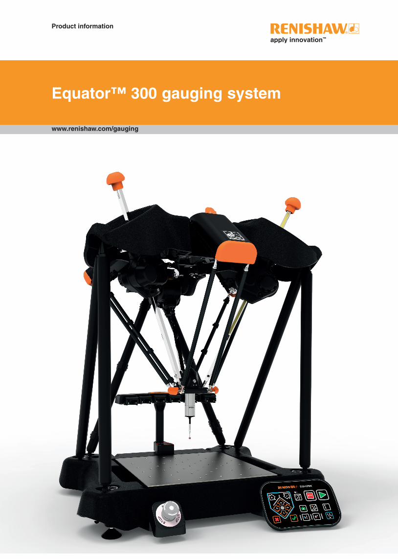
Equator™ 300 gauging system
www.renishaw.com/gauging
Product information

2
1. Introduction ..................................................................................................................................3
2. Regulatory information .................................................................................................................4
3. Safety information ........................................................................................................................6
4. Equator 300 gauging system specifications ...............................................................................10
5. Working volume .........................................................................................................................13
6. Equator gauging system overview .............................................................................................15
7. Initial set up ................................................................................................................................17
7.1 Unpacking ..................................................................................................................................18
7.2 Connecting cables......................................................................................................................19
7.3 Fitting the probe and stylus ........................................................................................................21
7.4 Hardware signals .......................................................................................................................24
8. Cleaning and maintenance ........................................................................................................26
9. Decommissioning .......................................................................................................................28
Contents

3
1. Introduction
This guide contains general information about the Equator 300 gauging system
For information not covered in this guide, please see:
• Equator Software Suite user guide
• Equator gauging system - MODUS programming guide

4
2. Regulatory information
Disclaimer
RENISHAW HAS MADE CONSIDERABLE EFFORTS TO ENSURE THE CONTENT OF THIS DOCUMENT IS CORRECT AT THE DATE OF PUBLICATION BUT MAKES NO WARRANTIES OR REPRESENTATIONS REGARDING THE CONTENT. RENISHAW EXCLUDES LIABILITY, HOWSOEVER ARISING, FOR ANY INACCURACIES IN THIS DOCUMENT.
EC declaration of conformity
Renishaw plc declares that the Equator 300, the Equator 300 Extended Height and the Equator controller comply with the applicable standards and regulations.
Renishaw plc hereby declares that the Equator 300, the Equator 300 Extended Height and the Equator controller is in compliance with the essential requirements and other relevant provisions of Directive 1999/5/EC.
Contact Renishaw plc or visit www.renishaw.com/Equator for the full EC declaration of conformity.
Patents
Features of Renishaw’s Equator and similar products are the subject of the following patents and patent applications:
CNw 100402873C China 0516/CNw/0CNw CN100464084C China 0584/CNw/0CNw CN1295484C China 0543/CNw/0EP 0470234 Europe 0187/EP/EP 0501710 Europe 0243/EP/EP 0543513 Europe 0226/EP/EP 0564152 Europe 0249/EP/EP 0674969 Europe 0317/EP/EP 0748436 Europe 0344/EP/EP 1086352 Europe 0439/EP/EP 1147377 Europe 0449/EP/EP 1368615 Europe 0495/EP/EP 1407152 Europe 0516/EP/EP 1446636 Europe 0543/EP/EP 1505362 Europe 0439/EP/EP 1528355 Europe 0543/EP/EP 1585903 Europe 0584/EP/EP 1777423 Europe 0516/EP/EP 548328 B Europe 0211/EP/EP 826138 B Europe 0376/EP/EP TR 2009 02853 T4 Europe 0516/EP/JP 2,510,804 Japan 0243/JP/0JPw 2002-541,444 Japan 0439/JPw/0JPw 2003-512,611 Japan 0449/JPw/0JPw 2004-534,189 Japan 0516/JPw/0JPw 2005-519277 Japan 0543/JPw/0JPw 2006-513380 Japan 0584/JPw/0JPw 3,004,050 Japan 0187/JPw/0
JPw 3,294,269 Japan 0211/JPw/0JP 3,341,922 Japan 0249/JP/0JPw 3,676,819 Japan 0376/JPw/0JP 3,827,748 Japan 0317/JP/0JPw 4062515 Japan 0495/JPw/0WO 2009/027660 P.C.T. 0746/WO/0USw 5,088,209 United States 0115/USw/0US 5,302,820 United States 0226/US/2US 5,323,540 United States 0243/US/2USw 5,327,657 United States 0211/USw/0US 5,339,535 United States 0243/US/0US 5,402,981 United States 0249/US/0USw 5,404,649 United States 0211/USw/2US 5,505,005 United States 0243/US/3US 5,813,287 United States 0317/US/2USw 5,861,953 United States 0344/USw/0USw 6,051,971 United States 0376/USw/0US 6,145,405 United States 0317/US/3US 6,336,375B1 United States 0317/US/4USw 6,430,833 B1 United States 0439/USw/0USw 6,588,333 B1 United States 0449/USw/0US 6,772,527 B1 United States 0590/US/0USw 6,909,983 B2 United States 0495/USw/0USw 7,079,969B2 United States 0543/USw/0USw 7146741B2 United States 0439/USw/2USw 7241070 B2 United States 0516/USw/0US 7568854B2 United States 0516/US/2

5
Trade marks
RENISHAW and the probe symbol used in the RENISHAW logo are registered trade marks of Renishaw plc in the United Kingdom and other countries. apply innovation and names and designations of other Renishaw products and technologies are trade marks of Renishaw plc or its subsidiaries.
All other brand names and product names used in this document are trade names, trade marks, or registered trade marks of their respective owners.
Warranty
Equipment requiring attention under warranty must be returned to your equipment supplier.
Unless otherwise specifically agreed in writing between you and Renishaw, if you purchased the equipment from a Renishaw company the warranty provisions contained in Renishaw’s CONDITIONS OF SALE apply. You should consult these conditions in order to find out the details of your warranty but in summary the main exclusions from the warranty are if the equipment has been:
• neglected, mishandled or inappropriately used; or
• modified or altered in any way except with the prior written agreement of Renishaw.
If you purchased the equipment from any other supplier, you should contact them to find out what repairs are covered by their warranty.
WEEE directive
The use of this symbol on Renishaw products and/or accompanying documentation indicates that the product should not be mixed with general household waste upon disposal. It is the responsibility of the end user to dispose of this product at a designated collection point for waste electrical and electronic equipment (WEEE) to enable reuse or recycling. Correct disposal of this product will help to save valuable resources and prevent potential negative effects on the environment. For more information, please contact your local waste disposal service or Renishaw distributor.
FCC information
Information to user (FCC Section 15.105)
This equipment has been tested and found to comply with the limits for a class A digital device, pursuant to part 15 of the FCC rules. These limits are designed to provide reasonable protection against harmful interference when the equipment is operated in a commercial environment. This equipment generates, uses and can radiate radio frequency energy and, if not installed and used in accordance with the installation manual, may cause harmful interference to radio communications. Operation of this equipment in a residential area is likely to cause harmful interference, in which case you will be required to correct the interference at your expense.
Information to user (FCC Section 15.21)
The user is cautioned that any changes or modifications not expressly approved by Renishaw plc or authorised representative could void the user’s authority to operate the equipment.
TÜV
This equipment has been independently certified by TÜV Product Services in accordance with OSHA (US) and SCC (Canada) requirements to the standards UL61010-1 Third Edition and CAN/CSA-C22-2 No. 61010-1 Third Edition.
REACH regulation
Information required by Article 33(1) of Regulation (EC) No. 1907/2006 (“REACH”) relating to products containing substances of very high concern (SVHCs) is available at: www.renishaw.com/REACH
2
6
3. Safety information
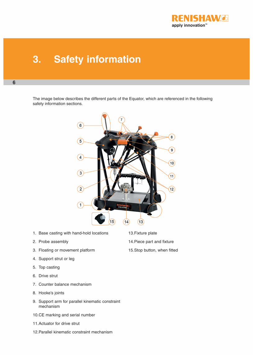
1. Base casting with hand-hold locations
2. Probe assembly
3. Floating or movement platform
4. Support strut or leg
5. Top casting
6. Drive strut
7. Counter balance mechanism
8. Hooke’s joints
9. Support arm for parallel kinematic constraint mechanism
10. CE marking and serial number
11. Actuator for drive strut
12. Parallel kinematic constraint mechanism
The image below describes the different parts of the Equator, which are referenced in the following safety information sections.
13. Fixture plate
14. Piece part and fixture
15. Stop button, when fitted
7
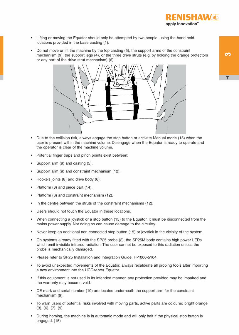
• Lifting or moving the Equator should only be attempted by two people, using the-hand hold locations provided in the base casting (1).
• Do not move or lift the machine by the top casting (5), the support arms of the constraint mechanism (9), the support legs (4), or the three drive struts (e.g. by holding the orange protectors or any part of the drive strut mechanism) (6)
• Due to the collision risk, always engage the stop button or activate Manual mode (15) when the user is present within the machine volume. Disengage when the Equator is ready to operate and the operator is clear of the machine volume.
• Potential finger traps and pinch points exist between:
• Support arm (9) and casting (5).
• Support arm (9) and constraint mechanism (12).
• Hooke’s joints (8) and drive body (6).
• Platform (3) and piece part (14).
• Platform (3) and constraint mechanism (12).
• In the centre between the struts of the constraint mechanisms (12).
• Users should not touch the Equator in these locations.
• When connecting a joystick or a stop button (15) to the Equator, it must be disconnected from the mains power supply. Not doing so can cause damage to the circuitry.
• Never keep an additional non-connected stop button (15) or joystick in the vicinity of the system.
• On systems already fitted with the SP25 probe (2), the SP25M body contains high power LEDs which emit invisible infrared radiation. The user cannot be exposed to this radiation unless the probe is mechanically damaged.
• Please refer to SP25 Installation and Integration Guide, H-1000-5104.
• To avoid unexpected movements of the Equator, always recalibrate all probing tools after importing a new environment into the UCCserver Equator.
• If this equipment is not used in its intended manner, any protection provided may be impaired and the warranty may become void.
• CE mark and serial number (10) are located underneath the support arm for the constraint mechanism (9).
• To warn users of potential risks involved with moving parts, active parts are coloured bright orange (3), (6), (7), (9).
• During homing, the machine is in automatic mode and will only halt if the physical stop button is engaged. (15)
3

8
3.1 Electrical safety
The Equator gauging system is marked with one warning triangle, located on the rear of the controller. See the label below.
Where this symbol is displayed on the product, the user must refer to the user guide for information and safety advice
• There are no user serviceable parts inside this equipment.
• The Equator must be connected to a supply incorporating a protective earth conductor via a three core mains cable.
• The equipment is isolated from AC power by disconnection of the IEC mains connector. If any additional means of isolation is required, it must be specified and fitted by the machine manufacturer or the installer of the product. The isolator must be sited within easy reach of the operator and comply with IEC61010 and any applicable national wiring regulations for the country of installation.
• Ensure that fans on the ends of the controller are not obstructed.

9
3.2 Personal protective equipment information
To reduce the risk of injury, the wearing of safety goggles and safety shoes is recommended when working within the vicinity of this machine.*
Never lean on any part of the machine, and keep a minimum of one metre clearance zone around the volume of the machine when it is operating.The Equator controller can be placed either standing or lying on its side, but should be given a reasonable protection from liquid spillage.
The fans for cooling the equipment must not be obstructed. Fans are located on the front and back of the controller. Ensure that the Equator controller fans are located at least 10 cm from any surface.
*NOTE: Customers should complete their own risk assessment on delivery of machine to define their own PPE requirements.
10
4. Equator 300 gauging system specifications
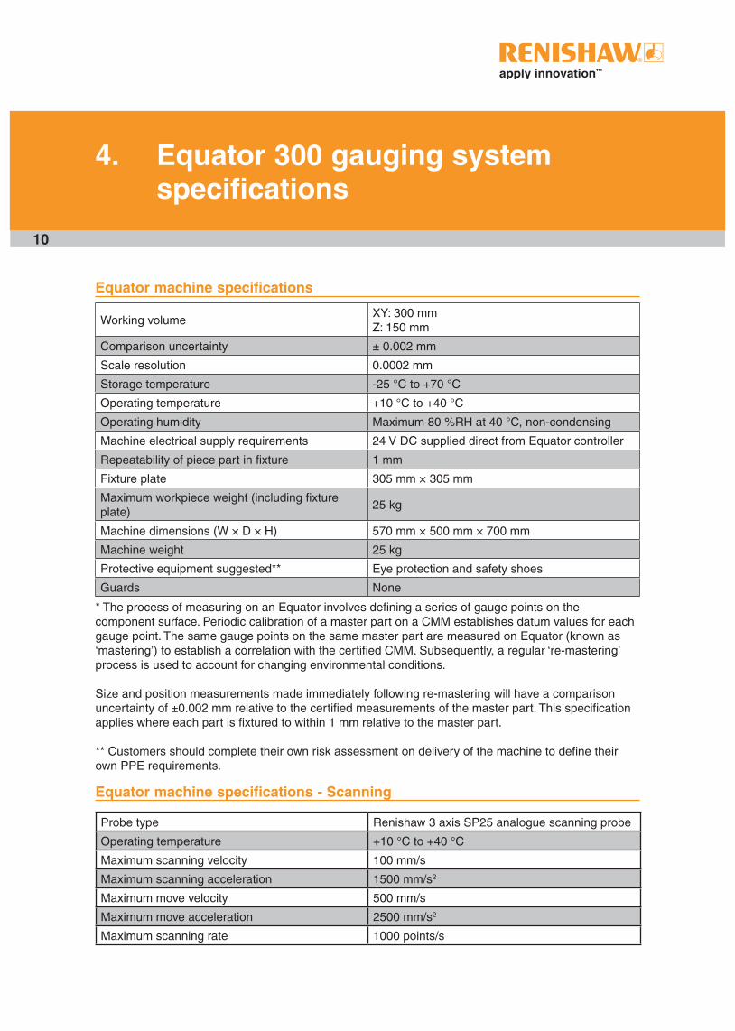
Equator machine specifications
Working volumeXY: 300 mmZ: 150 mm
Comparison uncertainty ± 0.002 mm
Scale resolution 0.0002 mm
Storage temperature -25 °C to +70 °C
Operating temperature +10 °C to +40 °C
Operating humidity Maximum 80 %RH at 40 °C, non-condensing
Machine electrical supply requirements 24 V DC supplied direct from Equator controller
Repeatability of piece part in fixture 1 mm
Fixture plate 305 mm × 305 mm
Maximum workpiece weight (including fixture plate)
25 kg
Machine dimensions (W × D × H) 570 mm × 500 mm × 700 mm
Machine weight 25 kg
Protective equipment suggested** Eye protection and safety shoes
Guards None
* The process of measuring on an Equator involves defining a series of gauge points on the component surface. Periodic calibration of a master part on a CMM establishes datum values for each gauge point. The same gauge points on the same master part are measured on Equator (known as ‘mastering’) to establish a correlation with the certified CMM. Subsequently, a regular ‘re-mastering’ process is used to account for changing environmental conditions.
Size and position measurements made immediately following re-mastering will have a comparison uncertainty of ±0.002 mm relative to the certified measurements of the master part. This specification applies where each part is fixtured to within 1 mm relative to the master part.
** Customers should complete their own risk assessment on delivery of the machine to define their own PPE requirements.
Equator machine specifications - Scanning
Probe type Renishaw 3 axis SP25 analogue scanning probe
Operating temperature +10 °C to +40 °C
Maximum scanning velocity 100 mm/s
Maximum scanning acceleration 1500 mm/s2
Maximum move velocity 500 mm/s
Maximum move acceleration 2500 mm/s2
Maximum scanning rate 1000 points/s

11
Equator machine specifications - Touch Trigger
Probe type Renishaw 3 axis TP20 kinematic touch-trigger probe
Operating temperature +10 °C to +40 °C
Maximum touch point velocity 10 mm/s
Maximum touch acceleration 1500 mm/s2
Maximum move velocity 500 mm/s
Maximum move acceleration 2500 mm/s2
Equator machine labels
A warning label on each of the three support arms for the constraint mechanism warns not to lift the machine by the support arms. The Equator machine should only be lifted using the four hand holds on the base casting.
Equator controller specifications and electrical ratings
Controller electrical supply requirements 100 V AC - 240 V AC ±10%, 50 Hz - 60 Hz
Maximum rated power consumption 300 W
Maximum power consumption* 190 W
Typical power consumption** 100 W
Controller dimensions (W × D × H)*** 130 mm × 320 mm × 350 mm
Controller weight 8 kg
Communication with Equator PCIexpress
User input devices Keyboard and mouse (USB 2.0)
Display type VGA monitor
Display resolution 1280 p × 1024 p
USB hub**** 2 front, 4 back (USB 2.0)
Ethernet ports 1 × RJ45 connector
* Peak consumption at power-up ** 3-axis gauging system taking touch points under DCC control + peak consumption at power-up*** Allow an additional 100 mm for cable connectors and cables**** Rear USB ports are for keyboard, mouse and MODUS dongle only, they do not support general plug and play devices.
Operating conditions
The Equator controller is specified to operate under the following conditions as defined in BS EN 61010-1:2001.
Altitude Maximum 2000 m
Operating temperature* +10 °C to +40 °C
Storage temperature -25 °C to +70 °C
Relative humidity Maximum 80% RH at 40 °C, non-condensing
Transition voltages Installation category II
Pollution degree 2
* System tested safe at 5 °C to 55 °C, however the probe will give accurate data in the range 10 °C to 40 °C.
4
12
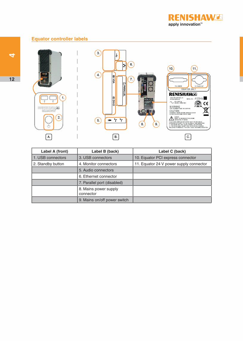
Equator controller labels
Label A (front) Label B (back) Label C (back)
1. USB connectors 3. USB connectors 10. Equator PCI express connector
2. Standby button 4. Monitor connectors 11. Equator 24 V power supply connector
5. Audio connectors
6. Ethernet connector
7. Parallel port (disabled)
8. Mains power supply connector
9. Mains on/off power switch
4
13
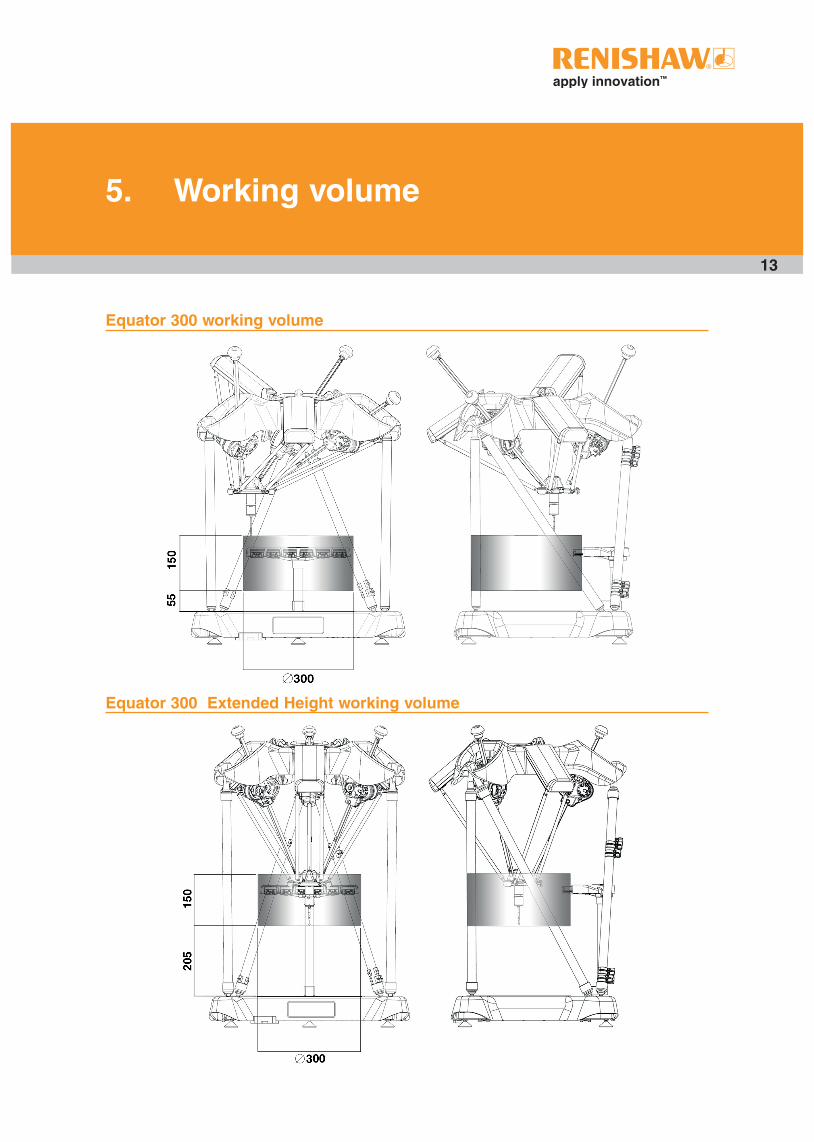
5. Working volume
Equator 300 working volume
Equator 300 Extended Height working volume
14
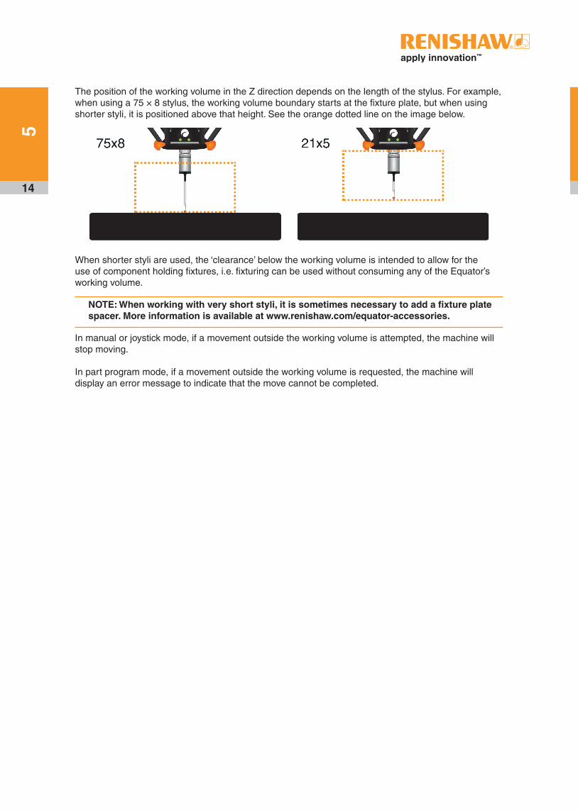
The position of the working volume in the Z direction depends on the length of the stylus. For example, when using a 75 × 8 stylus, the working volume boundary starts at the fixture plate, but when using shorter styli, it is positioned above that height. See the orange dotted line on the image below.
When shorter styli are used, the ‘clearance’ below the working volume is intended to allow for the use of component holding fixtures, i.e. fixturing can be used without consuming any of the Equator’s working volume.
NOTE: When working with very short styli, it is sometimes necessary to add a fixture plate spacer. More information is available at www.renishaw.com/equator-accessories.
In manual or joystick mode, if a movement outside the working volume is attempted, the machine will stop moving.
In part program mode, if a movement outside the working volume is requested, the machine will display an error message to indicate that the move cannot be completed.
5

15
6. Equator gauging system overview
The Equator gauging system comprises the Equator gauging machine, the Equator Controller and the probing system.
The Equator Controller supplies the power to the Equator machine as well as running the front end software.
The Equator has a cylindrical working envelope with the dimensions Ø300 mm × 150 mm.
The Equator gauging system is delivered fully assembled and is connected to a single phase power supply.
Operator interaction with the machine is by use of the shop floor interface Organiser, which handles and runs part-specific gauging programs.
The Operator Equator system includes the following components:
• Equator gauging machine
• Controller unit
• Flat screen monitor (1280 p × 1024 p resolution DVI or VGA)
• Keyboard
• Mouse
• Probe system
• EQR-6 stylus autochange rack
• Calibration artefact and styli
• Stop button or joystick
• One or more fixture plates (as quantity ordered)
• Organiser software
The programmable Equator system includes all of the above as well as the following components:
• Joystick
• MODUS Equator software
• USB dongle (enables MODUS Equator software)
NOTE: Further styli may be required, dependent on the user's requirements. More information is available at http://www.renishaw.com/styli.

16
1. Base casting with hand hold locations
2. Probe assembly
3. Floating or movement platform
4. Support strut or leg
5. Top casting
6. Drive strut
7. Counter balance mechanism
8. Hooke's joints
9. Support arm for parallel kinematic constraint mechanism
10. CE marking and serial number
11. Actuator for drive strut
12. Parallel kinematic constraint mechanism
13. Fixture plate
14. Piece part and fixture
15. Stop button, when fitted
6

17
7. Initial set up
The following section describes how to set up the Equator gauging system hardware:
7.1 Unpacking ..................................................................................................................................18
7.2 Connecting cables......................................................................................................................19
7.3 Fitting the probe and stylus ........................................................................................................21
7.4 Hardware signals .......................................................................................................................24

18
When the Equator has been removed from its transit packaging according to the instructions attached to the box, please follow the instructions in the following sections to start the system.
Contents of boxes
The Equator gauging system is delivered in several boxes. The larger box contains the machine and relevant accessories, other boxes contain the controller, stop button or joystick, probe kit and relevant accessories.
Transporting the Equator
When placed in its original packaging, the Equator machine can be moved by forklift or sack truck. Over shorter distances, it can be moved manually by two people using the hand holds on the side of the larger box.
The system should be transported in the original Equator packaging to ensure that no parts get lost or damaged.
The Equator machine should only ever be lifted by two people. Use the hand holds on the four corners of the base casting.
Equator machine positioning
The Equator system needs to be placed on a flat and sturdy surface. It is advised that a 1 m diameter clearance of other objects is established to avoid collisions.
It is suggested that the monitor and the joystick (if fitted) are located near the machine so that operational information can be seen by the operator.
Equator controller positioning
The controller can be placed on either side of the Equator as preferred. It can be placed either standing or lying down.
Ensure that the fan intakes at the front and outlets at the rear do not become blocked in any way. Allow 10 cm distance between fan intakes and outlets to any surface.
7.1 Unpacking
19
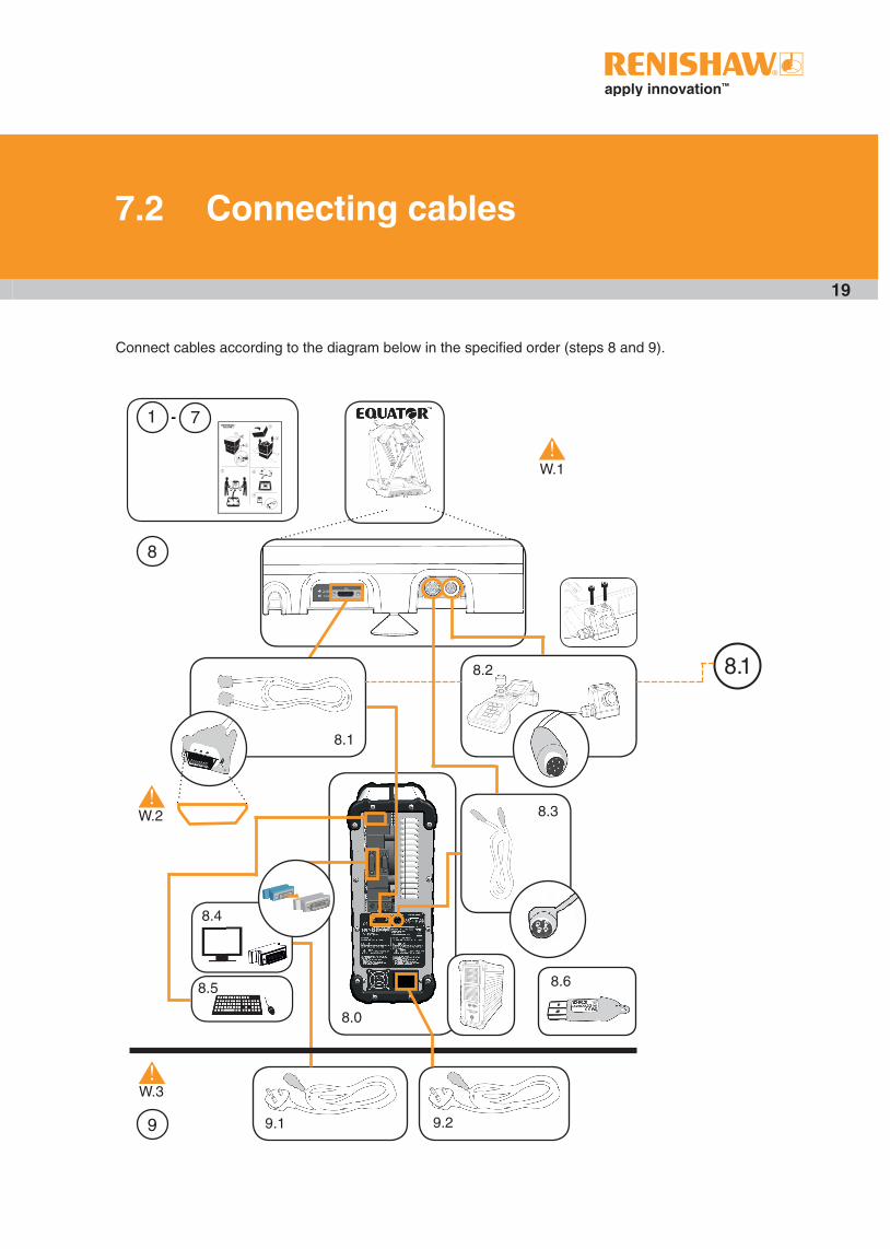
7.2 Connecting cables
8.2
8.3
8.0
8.1
9.1 9.2
W.1
W.2
W.3
-
!
!
!
8.6
1 7
8
9
8.1
8.4
8.5
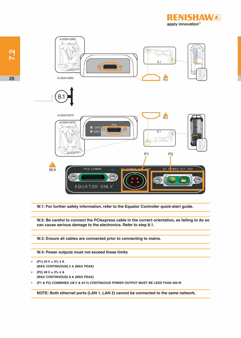
Connect cables according to the diagram below in the specifi ed order (steps 8 and 9).
20
W.1: For further safety information, refer to the Equator Controller quick-start guide.
W.2: Be careful to connect the PCIexpress cable in the correct orientation, as failing to do so can cause serious damage to the electronics. Refer to step 8.1.
W.3: Ensure all cables are connected prior to connecting to mains.
W.4: Power outputs must not exceed these limits
• (P1) 24 V ± 3% 4 A
(MAX CONTINUOUS) 5 A (MAX PEAK)
• (P2) 48 V ± 3% 4 A
(MAX CONTINUOUS) 8 A (MAX PEAK)
• (P1 & P2) COMBINED (48 V & 24 V) CONTINUOUS POWER OUTPUT MUST BE LESS THAN 300 W
NOTE: Both ethernet ports (LAN 1, LAN 2) cannot be connected to the same network.
A-5504-0065
A-5504-0065
8.1
W.2!
8.1
A-5504-0070
A-5504-0070
8.1
W.2!
W.4!
P1 P2
7.2
21
7.3 Fitting the probe and stylus
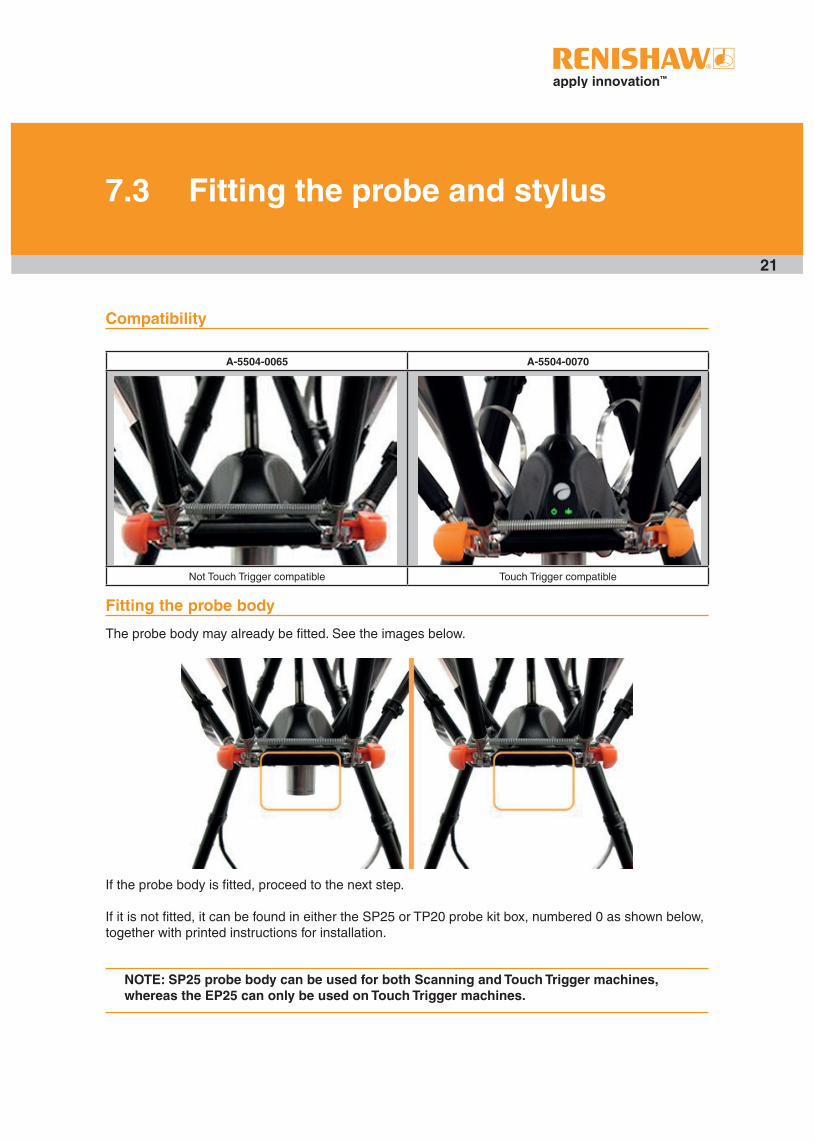
Compatibility
A-5504-0065 A-5504-0070
Not Touch Trigger compatible Touch Trigger compatible
Fitting the probe body
The probe body may already be fitted. See the images below.
If the probe body is fitted, proceed to the next step.
If it is not fitted, it can be found in either the SP25 or TP20 probe kit box, numbered 0 as shown below, together with printed instructions for installation.
NOTE: SP25 probe body can be used for both Scanning and Touch Trigger machines, whereas the EP25 can only be used on Touch Trigger machines.
22
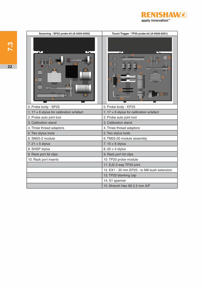
Scanning - SP25 probe kit (A-5504-0205) Touch Trigger - TP20 probe kit (A-5926-0201)
0. Probe body - SP25 0. Probe body - EP25
1. 17 × 6 stylus for calibration artefact 1. 17 × 6 stylus for calibration artefact
2. Probe auto joint tool 2. Probe auto joint tool
3. Calibration stand 3. Calibration stand
4. Three thread adaptors 4. Three thread adaptors
5. Two stylus tools 5. Two stylus tools
6. SM25-2 module 6. TM25-20 module assembly
7. 21 × 5 stylus 7. 10 × 6 stylus
8. SHSP stylus 8. 20 × 4 stylus
9. Rack port lid clips 9. Rack port lid clips
10. Rack port inserts 10. TP20 probe module
11. EJ2 2-way TP20 joint
12. EX1 - 35 mm EP25 - to M8 bush extension
13. TP20 blanking cap
14. S1 spanner
15. Wrench Hex S6 2.5 mm A/F
7.3
23
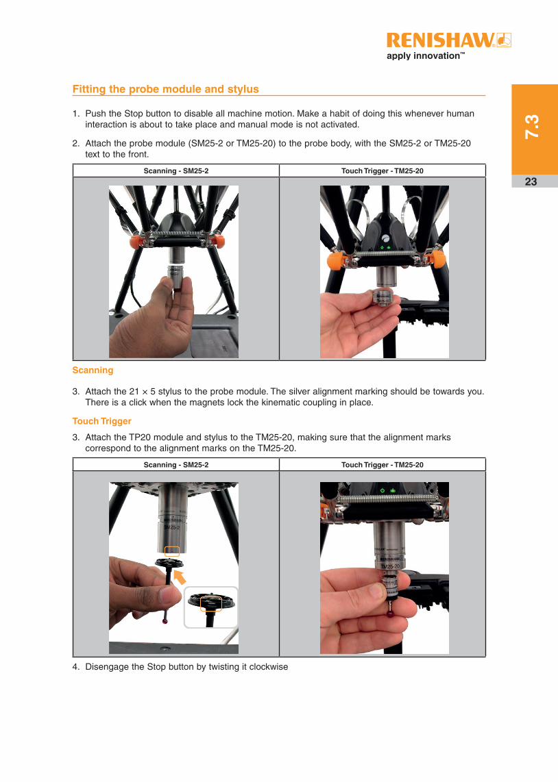
Fitting the probe module and stylus
1. Push the Stop button to disable all machine motion. Make a habit of doing this whenever human interaction is about to take place and manual mode is not activated.
2. Attach the probe module (SM25-2 or TM25-20) to the probe body, with the SM25-2 or TM25-20 text to the front.
Scanning - SM25-2 Touch Trigger - TM25-20
Scanning
3. Attach the 21 × 5 stylus to the probe module. The silver alignment marking should be towards you. There is a click when the magnets lock the kinematic coupling in place.
Touch Trigger
3. Attach the TP20 module and stylus to the TM25-20, making sure that the alignment marks correspond to the alignment marks on the TM25-20.
Scanning - SM25-2 Touch Trigger - TM25-20
4. Disengage the Stop button by twisting it clockwise
7.3
24
7.4 Hardware signals
A-5504-0065 machines
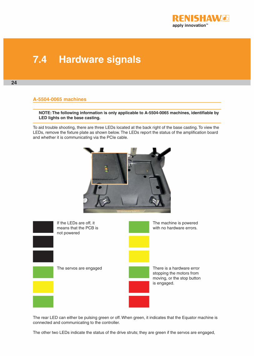
NOTE: The following information is only applicable to A-5504-0065 machines, identifiable by LED lights on the base casting.
To aid trouble shooting, there are three LEDs located at the back right of the base casting. To view the LEDs, remove the fixture plate as shown below. The LEDs report the status of the amplification board and whether it is communicating via the PCIe cable.
If the LEDs are off, it means that the PCB is not powered
The servos are engaged
The machine is powered with no hardware errors.
There is a hardware error stopping the motors from moving, or the stop button is engaged.
The rear LED can either be pulsing green or off. When green, it indicates that the Equator machine is connected and communicating to the controller.
The other two LEDs indicate the status of the drive struts; they are green if the servos are engaged,
25
The rear LED can either be pulsing green or off. When green, it indicates that the Equator machine is connected and communicating to the controller.
The other two LEDs indicate the status of the drive struts; they are green if the servos are engaged, orange if the system is powered and ready to engage, and red if there is an error preventing servos from engaging.
The image above shows some of the possible LED states.
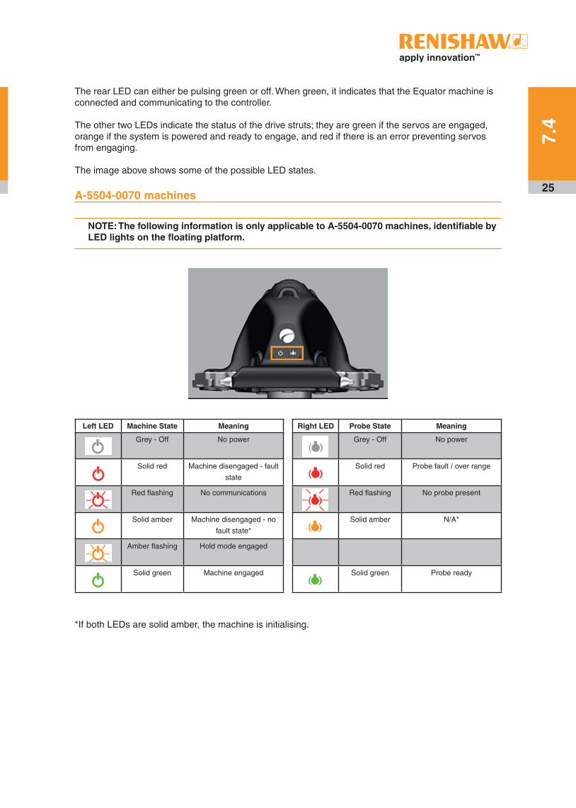
A-5504-0070 machines
NOTE: The following information is only applicable to A-5504-0070 machines, identifiable by LED lights on the floating platform.
Left LED Machine State Meaning
Grey - Off No power
Solid red Machine disengaged - fault
state
Red flashing No communications
Solid amber Machine disengaged - no
fault state*
Amber flashing Hold mode engaged
Solid green Machine engaged
Right LED Probe State Meaning
Grey - Off No power
Solid red Probe fault / over range
Red flashing No probe present
Solid amber N/A*
Solid green Probe ready
*If both LEDs are solid amber, the machine is initialising.
7.4

26
8. Cleaning and maintenance
NOTE: The Equator and the Equator controller have no user-serviceable parts inside.
Cleaning
The Equator 300 cleaning kit (A-5504-9055) provides everything needed to ensure the clean and reliable running of an Equator machine. The cleaning kit includes replacement dust filters and cleaning products which have been tested and proven as non-abrasive and non-corrosive.
CAUTION: Do not use solvents.
Maintenance
Following the simple maintenance procedures given below will prolong the operational life and provide continued high performance of the system. The user should determine the frequency of inspection and maintenance actions according to the conditions of use.
The Equator machine has no user-serviceable parts.
The Equator controller has fan filters needing regular replacement to ensure satisfactory cooling of internal parts. The Equator controller has no internal serviceable parts. In the event of a problem, please contact your supplier for assistance. An Equator controller Fan Filter Kit (A-5696-0120) containing 12 fan filters can be purchased from Renishaw ensuring 6 months worth of filters for high contamination environments.
Repair and replacement of parts should only be carried out by a Renishaw representative. Renishaw offers a maintenance contract which provides overnight Repair-By-Exchange (RBE) and the option to have a consignment unit on site.
CAUTION: Always adhere to the instructions given in the Safety information section of this guide. Failure to do so could adversely affect the performance of the system and/or lead to personal injury.

27
SP25 maintenance
SP25 maintenance is described in the SP25 user guide.
TP20 maintenance
TP20 maintenance is described in the TP20 user guide.
Styli maintenance
Stylus balls, threads and mating faces should be cleaned using a proprietary cleaning cloth or solvent. Stylus balls should be regularly inspected for damage or ‘pick-up’ of component material (a problem sometimes encountered with continuous scanning). Renishaw offers a range of ball materials suited to scanning of different component materials. See Renishaw’s styli catalogue (part number H-1000-3200), which can be downloaded from www.renishaw.com/styli.
Connector maintenance
Regular checks should be made to make sure that the electrical connectors are properly located.
Controller fan filter maintenance
The fan intakes on the front of the Equator controller have filters to prevent dust and other particles from entering. These filters should be replaced regularly to prevent overheating of the controller.When replacing the filters, ensure that the controller is powered down and unplug the power supply from the mains. Carefully release the snap fit clips on the covers to reveal the filters. Once the filters are replaced, locate the covers and clip back into position. A slight click may be audible when the covers locate.
Liquid spillage
• Reasonable measures should be taken to protect the system (machine and controller) from liquid spillage.
• If a spillage occurs, exercise caution when unplugging the power connector from the wall socket.
• Soak and wipe up the liquid using a dry, lint-free cloth.
• Inspect the system to see if any liquid ingress has occurred. If not, the power supply can be reconnected.
If liquid ingress occurs to the machine/controller, this is a potential electrical hazard, do not reconnect the power connector. Please send the unit back to the supplier for replacement at customer’s cost. This type of damage is not covered by the warranty or RBE scheme, so please ensure that the machine/controller is given the protection required for the environment.
8

28
9. Decommissioning
1. Remove any fixture plates from the Equator.
2. Disconnect all power supplies.
3. Unplug the Equator system from the controller.
4. Disconnect screen, mouse and keyboard from the controller.
5. Unplug the stop button.
6. If returning the system to Renishaw as part of the RBE scheme, repackage the system using the reverse of the unpacking instructions. If not, dispose of system according to WEEE regulations (see the WEEE information section).

RENISHAW HAS MADE CONSIDERABLE EFFORTS TO ENSURE THE CONTENT OF THIS DOCUMENT IS CORRECT AT THE DATE OF PUBLICATION BUT MAKES NO WARRANTIES OR REPRESENTATIONS REGARDING THE CONTENT. RENISHAW EXCLUDES LIABILITY, HOWSOEVER ARISING, FOR ANY INACCURACIES IN THIS DOCUMENT.
© 2019 Renishaw plc. All rights reserved. Renishaw reserves the right to change specifications without notice.RENISHAW and the probe symbol used in the RENISHAW logo are registered trade marks of Renishaw plc in the United Kingdom and other countries. apply innovation and names and designations of other Renishaw products and technologies are trade marks of Renishaw plc or its subsidiaries.All other brand names and product names used in this document are trade names, trade marks or registered trade marks of their respective owners.
About Renishaw
Renishaw is an established world leader in engineering technologies, with a strong history of innovation in product development and manufacturing. Since its formation in 1973, the company has supplied leading-edge products that increase process productivity, improve product quality and deliver cost-effective automation solutions.
A worldwide network of subsidiary companies and distributors provides exceptional service and support for its customers.
Products include:
• Additive manufacturing and vacuum casting technologies for design, prototyping, and production applications
• Dental CAD/CAM scanning systems and supply of dental structures
• Encoder systems for high-accuracy linear, angle and rotary position feedback
• Fixturing for CMMs (co-ordinate measuring machines) and gauging systems
• Gauging systems for comparative measurement of machined parts
• High-speed laser measurement and surveying systems for use in extreme environments
• Laser and ballbar systems for performance measurement and calibration of machines
• Medical devices for neurosurgical applications
• Probe systems and software for job set-up, tool setting and inspection on CNC machine tools
• Raman spectroscopy systems for non-destructive material analysis
• Sensor systems and software for measurement on CMMs
• Styli for CMM and machine tool probe applications
For worldwide contact details, visit www.renishaw.com/contact
Part no.: H-5504-8705-07-BIssued: 03.2019
T +44 (0) 1453 524524F +44 (0) 1453 524901E [email protected]
www.renishaw.com
Renishaw plc
New Mills, Wotton-under-EdgeGloucestershire, GL12 8JRUnited Kingdom