Embed Size (px)
Citation preview
1
COMPARISION OF CODE RULESWITH FEA RESULTS
Obeydi.Maryam
2
Table of ContentsABSTRACT............................................................................................................................... ...........................3
1. OPENING DESIGN METHOD AND THEIR LIMITATIONS IN ASME ..............................................................3
2. DESIGN METHODS........................................................................................................................ .............3
2.1) ASME SEC. VIII DIV.1: AREA COMPENSATION .................................................................................5
2.2) DESIGN OF PLATE AND SHELL STRUCTURES: PRESSURE AREA THEORY ..............................................6
2.3) ASME SEC. VIII DIV.2: PRESSURE AREA ..............................................................................................8
3. SUMMARY OF RESULTS...........................................................................................................................13
APPENDIX 1 ............................................................................................................................... ......................20
APPENDIX 2 ............................................................................................................................... ......................23

3
ABSTRACTDesign of openings in shell and heads is one of themost important parts of the mechanical design ofpressure vessels and due to its importance ASME codehas devoted more than one section to this issue. Eachsection has its own approach, theoretical bases and ofcourse limitations. Some of them can be usedalternatively and for some problems requirements ofmore than one section has to be fulfilled. The fact thatmultiple set of rules for design of openings exist inASME has made it a little confusing for designers tofigure out which section should be applied to eachspecific problem. In this paper we have tried toprovide designers with a deeper insight toward use ofASME code for design of openings by opening up thetheoretical background of some sections, solvingillustrative examples and comparison of FEA resultswith CODE results.In the first chapter all ASME sections which arerelated to design of opening has been listed andapplication and limitation of each one is specified,furthermore it has been clarified when some sectionsshould be used instead of or in addition to othersections.In the second chapter the area replacement methodof division 1 and the pressure area method of division2 being the two most important design methods havebeen investigated. The theoretical basis of pressurearea method according to Jawad has been explained.An example is solved by FEA, to verify theassumptions of analytical formulation.In the third chapter an example is solved with threemethods: Pressure area (Div.2), Area Compensation(Div.1) and FEA and results are summarized in tablesand curves, to facilitate comparison of methods.Finally, calculation procedures of area compensationand pressure area method are depicted in twoflowcharts which are given in appendix 1 and 2.
1. OPENING DESIGN METHOD ANDTHEIR LIMITATIONS IN ASME
In table 1 all parts of ASME which may be used fordesign of nozzle reinforcement are listed andlimitation of each one is specified. Some sections canbe used instead of each other and in some cases morethan one Section should be applied in order toproperly design an opening.
For example for openings which fall in to limits of UG36 and under internal pressure Rules of UG 37 to UG42 or appendix 1 10 or appendix 1 9 may be used.But for nozzles exceeding limits of UG 36,supplemental rules of appendix 1 7 shall be satisfiedin addition to the rules of UG 37 to UG 42.Alternatively, openings in cylindrical or conical shellsexceeding UG 36 limits may be designed for internalpressure, using only the rules of 1 10.Openings in vessels not subjected to rapidfluctuations in pressure do not require reinforcementif requirement of UG 36(c)(3) is satisfied.Appendix 1 10 is based on pressure area methodwhich can be used for all nozzles on cylinders andcones including large openings. It is an alternativemethod to UG 37 procedure which results in a moreaccurate and economical design. But it is notapplicable to external pressure cases and also doesnot specify any provisions for weld design. So whenappendix 1 10 is applied welds should be designedaccording to ASME DIV.2 part 4 5 14.ASME DIV.2 part 4 5 is similar to the method ofappendix 1 10 but covers both internal and externalpressure cases.
2. DESIGN METHODSThe traditional area replacement method has beenused in ASME pressure vessel and piping codes formany years. The area replacement concept requiresthat the metal removed to make an opening bereplaced by an equal area of reinforcement within aprescribed region around the opening. This concept isstill used in the ASME B&PV Code, Section VIII,Division1, paragraph UG 37 for the design ofreinforcement at openings in shells and formedheads. However, a substantial amount of informationaccumulated in recent years indicates that the areareplacement method may lead to excessiveconservatism in some applications.

4
In order to overcome the over conservatism of thearea replacement method, the pressure area methodwas recently introduced in the ASME B&PV Code,Section VIII, Division 2, Part4, paragraph 4.5.Thepressure area method is based on ensuring that theresistive internal force provided by the material isgreater than or equal to the reactive load from theapplied internal pressure. In this paper the basictheory behind the pressure area method that isincorporated in the ASME B&PV Code,
Section VIII, Division 2 is presented. The nozzle rulesof ASME B&PV Code, Section VIII, Division 2, Part 4,paragraph 4.5 along with a commentary providingbackground and insight to the rules is provided.
REFERENCE SHELL IDor thk. NOZZLE ID PRESSURE RATIO MATERIAL PARENT ATTACHMENT
UG 36 to UG43 are
applicable
<=60”(1500mm)
Di /2 <20”(500mm) Pin , Pext.
>60”(1500mm)
Di /3< 40”(1000mm) Pin , Pext.
Appendix1 7
(Largeopening)
=>60”(1500mm)
=>40”(1000mm)
And>3.4 (Rt)^1/2
Pin , Pext. Rn/R<0.7Radial Nozzle in a
Cylindrical & Conical Shell.Half alfa 30
UG 36(c)(3)(Small
opening)
Thk. <=3 8 in.(10 mm)
31 2 in.(89 mm) Pin , Pext.
Thk.>3 8 in.(10 mm);
23 8 in.(60 mm)
Appendix1 9
Integrallyreinforced type
of nozzles<=24” (600mm)
Pin
YS/TS<0.8opening diameter: dmvessel diameter: Dmvessel thickness: tFor (dm/Dm) > 0.5
(Dm/t) 100For (dm/Dm) 0.5
(Dm/t) 250
UCS 23UHA 23
Radial Nozzle in aCylindrical & Conical Shell
Appendix1 10 Pin
Radial & hillside nozzles ina Cylindrical & Conical
Shell..
SEC VIIIDIV.2
PART 4.5Pin , Pext.
IDs/Ts<= 400mmthe ratio of the
diameteralong the major
axis to the diameteralong the minor axisof the finished nozzleopening shall be lessthan or equal to 1.5.
Table 1) All parts of ASME which may be used for design of nozzle reinforcement
5
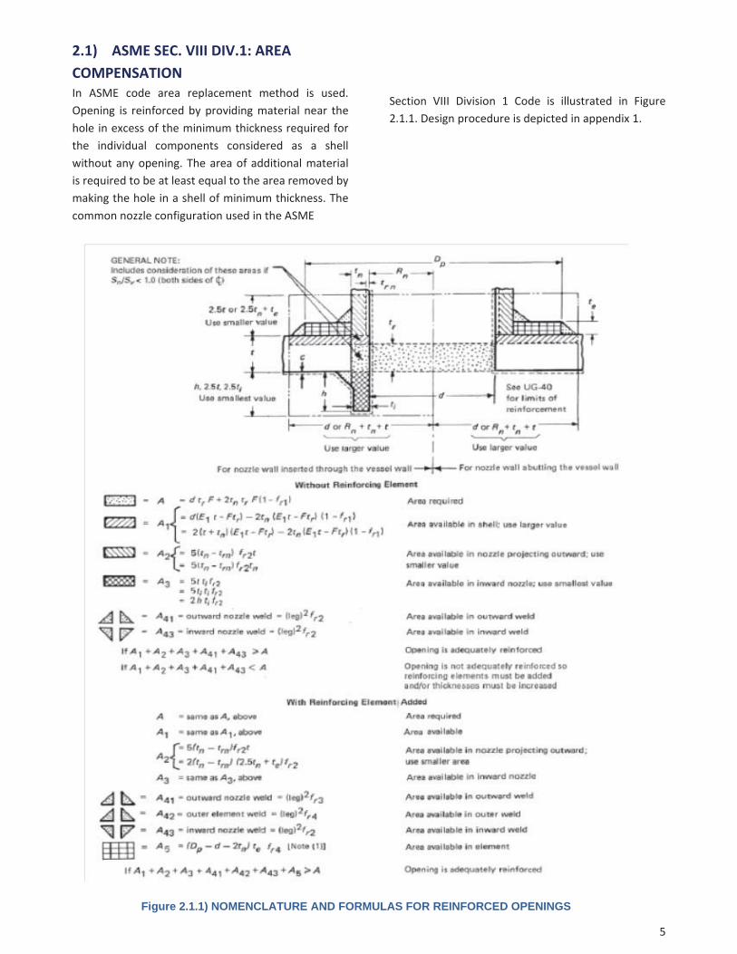
2.1) ASME SEC. VIII DIV.1: AREACOMPENSATIONIn ASME code area replacement method is used.Opening is reinforced by providing material near thehole in excess of the minimum thickness required forthe individual components considered as a shellwithout any opening. The area of additional materialis required to be at least equal to the area removed bymaking the hole in a shell of minimum thickness. Thecommon nozzle configuration used in the ASME
Section VIII Division 1 Code is illustrated in Figure2.1.1. Design procedure is depicted in appendix 1.
Figure 2.1.1) NOMENCLATURE AND FORMULAS FOR REINFORCED OPENINGS

6
2.2) DESIGN OF PLATE AND SHELLSTRUCTURES: PRESSURE AREA THEORY
The pressure area analysis is based on the conceptthat the pressure contained in a given area within ashell must be resisted by the metal close to that area.Referring to fig. 2.2.1(a), the total force in the shadedarea of the cylinder is (r)(P)(L) while the forcesupported by the available metal is (L)(t)( ). Equatingthese two expressions results in t = pr/ which is theequation for the required thickness of a cylindricalshell. Similarly for spherical shells, Fig. 2.2.1(b), Gives
Referring to Fig. 2.2.2a, it is seen that pressure
area A is contained by the cylinder wall and pressurearea B is contained by the nozzle wall. However,pressure area C is not contained by any material. Thuswe must add material, M, at the junction. The area ofmaterial M is given by
For a spherical shell, the required area, M, from Fig.2.2.2b is,
Figure 2.2.1) PRESSURE AREA INTERACTION Figure 2.2.2) NOZZLE JUNCTIONS

7
The required area is added either to the shell, nozzle,or as a reinforcing pad as shown in Fig. 2.2.3.The pressure area method can also be applied forjunctions between components as shown in Fig. 2.2.4.Referring to Fig.2.2.4a, the spherical shell mustcontain the pressure within area ABC. The cylindricalshell contains the pressure within area AOCD. At pointA where the spherical and cylindrical shells intersect,the pressure area to be contained at point A is givenby AOC. However, because area AOC is used both inthe ABC area for sphere and AOCD for the cylinder,and because it can be used only once, this area mustbe subtracted from the total calculated pressure inorder to maintain equilibrium. In other words, thisarea causes compressive stress at point A. the arearequired is given by:
Where , is the allowable compressive stress.In Fig. 2.2.4b, pressure area A is contained by the
cylindrical shell and area C by the spherical shell. AreaB is contained by the transition shell. The transitionshell is in tension because area B is used neither in thearea A nor area B calculations.In Fig. 2.2.4c, pressure area A is contained by thecone and area B by the cylinder. The transition shellbetween the cone and the cylinder contains pressurearea C which is in tension and area D which is incompression.Summation of areas C and D will determine the stateof stress in the transition shell.
Figure 2.2.3) NOZZLE REINFORCEMENT Figure 2.2.4) VARIOUS SHELL JUNCTIONS

8
Consequently, this part results in below formulas
which are the fundamental formulas for ASME SEC.
VIII DIV.2:
Where;
2.3) ASME SEC. VIII DIV.2: PRESSUREAREA
Based on this division to design a radial nozzle in acylindrical shell subject to pressure loading, theaverage local primary membrane stress and thegeneral primary membrane shall be determined asshown below:
Where :
fN = : force from internal pressure inthe nozzle outside of the vessel
fS = : force from internal pressure inthe shell
fY = : discontinuity force from pressure.
AT : total area within the assumed limits ofreinforcement.
R xs : shell radius for force calculation.
R xn : nozzle radius for force calculation.
R nc: radius of the nozzle opening in the vessel alongthe long chord, for radial nozzles R nc = R n
teff : effective thickness used in the calculation ofpressure stress near the nozzle opening.
The denominator can be expanded as below :

9
Figure 2.3.1) NOMENCLATURE FOR REINFORCED OPENINGS

10
Then total available area should be determined:
Where:
LR : effective length of the vessel wall
For integrally reinforced nozzles:
For nozzles with reinforcing pads:
LR = min [ LR1 , LR2 , LR3 ]
Di : inside diameter of a shell or head
Reff =0.5Di
for variable thickness openings Where, LH > L pr3 + t
for variable thickness openings Where, LH < L pr3 + t
Or, for uniform thickness openings
LH : effective length of nozzle wall outside the vessel
= min [ LH1 , LH2 , LH3 ]
for nozzles inserted through the vessel wall
for nozzles abutting the vessel wall
LI : effective length of nozzle wall inside the vessel =
min [ LI1 , LI2 , LI3 ]
A5 =min [ A5a , A5b ]
for nozzle inserted through the vessel wall
for nozzles abutting the vessel wall
Determine the maximum local primary membranestress at the nozzle intersection:

11
PL is determined from the calculated averagemembrane stress using a linear stress distribution.The assumed stress distribution is shown in Figure2.3.2. The stress increases from the hoop stress in theshell, at a distance of LR from the nozzle, to amaximum value in the shell equal to PL near theopening. In order to verify the assumed stressdistribution an example has been solved with FEA. Acylindrical shell with a nozzle opening has beenconsidered and hoop stress distribution for fivedifferent nozzle thicknesses has been obtained withFEA.The cylindrical shell inside diameter is equal to2000mm, its metal thickness is equal to 12mm and itis subjected to 1Mpa internal pressure. Five differentnozzle thicknesses has been considered for each ofwhich the membrane hoop stress has been evaluatedat five points located at 0, 40, 80, 120 and 160mmfrom the nozzle edge. The shell and the nozzle hasbeen modeled in workbench and meshed with 3dsolid elements ( Figure 2.3.4) stress linearizationhas been performed at specified locations to obtainmembrane stresses. The results are plotted in figure2.3.3 and tabulated in table 2.3.1. Each curve in figure2.3.3 shows the stress distribution corresponding to anozzle thickness. As it is evident in figure 2.3.3 for allnozzle thicknesses, membrane hoop stress rises orfalls in a linear trend. This confirms the assumption oflinear stress distribution that was made for calculationof the maximum local stress (Pl) from the averagestress ( .
Table 2.3.1) MEMBRANE STRESS IN SHELL FOR DIFFERENTNOZZLE THICKNESS
Another interesting fact which is shown in curves offigure 2.3.3 is the nozzle wall reinforcementcounteracting effect on stress concentration. As thenozzle wall thickness increases from 30mm to 90mmthe maximum local stress decreases. For nozzlethickness 30mm and 40mm the stress concentrationeffect is dominant, for nozzle thickness, 50mm, thestress concentration and the reinforcement effectsare in equilibrium and for nozzle thickness 70 and 90the reinforcement effect results in local stresses thatare even less than the circumferential hoop stress faraway from the nozzle edge.Stress contours are shown in figure 2.3.4, for all fivenozzle thicknesses.
distancefromnozzleedge
case DP 1 DP 2 DP 3 DP 4 DP 5
NozzleThk.(mm) 30 40 50 70 90
0
Mem
braneStress(M
pa)
127.89 99.68 81.80 62.51 54.25
40 105.69 90.05 80.70 70.34 65.35
80 87.71 82.95 80.07 77.18 74.92
120 84.77 82.47 81.03 79.99 78.96
160 81.80 81.78 81.82 82.35 82.09
Figure 2.3.2) ASSUMED STRESS DISTRIBUTION AT SHELLDISCONTINUITY
Figure 2.3.3) MEMBRANE STRESS IN SHELL FOR DIFFERENT NOZZLETHICKNESS

12
Nozzle Thickness = 30 mm Nozzle Thickness = 40 mm
Nozzle Thickness = 50 mm Nozzle Thickness = 70 mm
Nozzle Thickness = 90 mm
Figure 2.3.4) Stress counters showing the stress distribution in cylindrical shell with different nozzle thicknesses
13
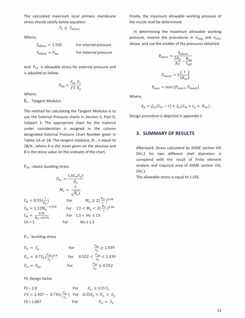
The calculated maximum local primary membranestress should satisfy below equation:
Where;
For internal pressure
For external pressure
And Fha is allowable stress for external pressure andis adjusted as follow:
Where;
Et : Tangent Modulus
The method for calculating the Tangent Modulus is touse the External Pressure charts in Section II, Part D,Subpart 3. The appropriate chart for the materialunder consideration is assigned in the columndesignated External Pressure Chart Number given inTables 1A or 1B. The tangent modulus, Et , is equal to2B/A , where A is the strain given on the abscissa andB is the stress value on the ordinate of the chart.
Fhe : elastic buckling stress
For
For
For 1.5 < 13
Ch = 1 For 1.5
Fic : buckling stress
For
For
For
FS: Design factor
FS = 2.0 For
For
FS = 1.667 For
Finally, the maximum allowable working pressure ofthe nozzle shall be determined:
In determining the maximum allowable workingpressure, reverse the procedures in andabove, and use the smaller of the pressures obtained.
Where,
Design procedure is depicted in appendix 1.
3. SUMMARY OF RESULTS
Afterward, Stress calculated by ASME section VIIIDIV.2 for two different shell diameters iscompared with the result of finite elementanalysis and required area of ASME section VIII,DIV.1.The allowable stress is equal to 1.5SE.

14
FEAMETHO
D
distance
from
nozzle
edge
case
DP1
DP2
DP3
DP4
DP5
allowable
Stress
(Mpa)
ShellID(m
m)
1500
1500
1500
1500
1500
Nozzle
ID(m
m)
300
350
400
450
500
0
MembraneStress(Mpa)
179.73
207.17
225.18
247.99
269.50
224.25
2514
0.30
150.40
159.59
173.10
183.38
224.25
5010
4.71
108.99
103.90
108.86
104.77
224.25
7586.42
85.21
73.77
68.18
65.36
224.25
100
79.73
75.00
66.12
61.46
56.78
224.25
125
76.96
72.83
64.99
64.94
59.85
224.25
150
76.33
73.55
63.51
59.79
56.55
224.25
RESU
LTpass
pass
fail
fail
fail
ASMESECVIII_
DIV.I
case
DP1
DP2
DP3
DP4
DP5
ShellID(mm)
1500
1500
1500
1500
1500
Nozzle
ID(m
m)
300
350
400
450
500
Area
Available(mm
2 )18
24.1
2013.8
2205.5
2396..2
1596.0
Area
Requ
ired(m
m2 )
1511
1761.8
2015.1
2267.2
1679.6
RESU
LTpass
pass
pass
pass
fail
ASMESECVIII_
DIV.II
distance
from
nozzle
edge
case
DP1
DP2
DP3
DP4
DP5
Allowable
Stress
(Mpa)
ShellID(mm)
1500
1500
1500
1500
1500
Nozzle
ID(m
m)
300
350
400
450
500
0
MembraneStress(Mpa)
160.90
178.70
196.10
213.20
230.00
224.25
3612
2.36
131.25
139.98
148.51
156.9
224.25
7283.84
83.84
83.84
83.84
83.84
224.25
100
83.84
83.84
83.84
83.84
83.84
224.25
RESU
LTpass
pass
pass
pass
fail
Figure
3.1)
STRE
SSIN
SHELL(FEA
METHO
D,AS
MEDIV.2)
ANDAR
EACA
LCULA
TIONDIV.1

15Figure 3.2) STRESS IN SHELL (FEA METHOD)

16
ASMESECVIII_
DIV.II
distance
from
nozzle
edge
case
DP1
DP2
DP3
DP4
DP5
allowable
Stress
(Mpa)
ShellID(mm)
2000
2000
2000
2000
2000
Nozzle
ID(m
m)
300
350
400
450
500
0
MembraneStress(Mpa)
177.90
196.10
214.00
231.60
249.10
224.25
6013
0.86
139.95
148.90
157.74
166.46
224.25
120
83.84
83.84
83.84
83.84
83.84
224.25
140
83.84
83.84
83.84
83.84
83.84
224.25
RESU
LTpass
pass
pass
fail
fail
ASMESECVIII_
DIV.I
case
DP1
DP2
DP3
DP4
DP5
ShellID(mm)
2000
2000
2000
2000
2000
Nozzle
ID(m
m)
300
350
400
450
500
Area
Available(mm
2 )22
0426
66.7
2921
3175.3
3429.6
Area
Requ
ired(m
m2 )
2184.9
2350.8
2686.9
3022.9
3359
RESU
LTpass
pass
pass
pass
pass
FEAMETHO
D
distance
from
nozzle
edge
case
DP1
DP2
DP3
DP4
DP5
allowable
Stress
(Mpa)
ShellID(mm)
2000
2000
2000
2000
2000
Nozzle
ID(m
m)
300
350
400
450
500
0
MembraneStress(Mpa)
187.70
212.26
229.46
250.69
267.20
224.25
2515
0.48
170.33
183.63
189.82
204.47
224.25
5011
7.87
123.85
136.32
132.29
136.99
224.25
7598.98
101.68
103.71
97.89
98.65
224.25
100
90.02
89.85
89.56
83.04
81.84
224.25
125
85.34
83.11
77.32
79.33
72.09
224.25
150
82.58
80.59
74.16
72.65
68.47
224.25
175
80.35
79.50
75.08
70.24
67.43
224.25
RESU
LTpass
pass
fail
fail
fail
Figure
3.3)
STRE
SSIN
SHELL(FEA
METHO
D,AS
MEDIV.2)
ANDAR
EACA
LCULA
TIONDIV.1

17Figure 3.4) STRESS IN SHELL BASED ON FEA METHOD

18
Figure 3.5) MAWP RESULTS (DIV. I via. Div. II)SHELL ID: FIX, NOZZLE THK.: VARIANT
Figure 3.6) MAWP RESULTS (DIV. I via. Div. II)SHELL ID: VARIANT, NOZZLE THK.: FIX
19
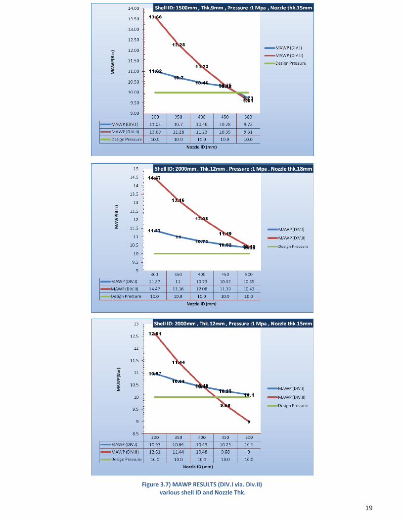
Figure 3.7) MAWP RESULTS (DIV.I via. Div.II)various shell ID and Nozzle Thk.

20
APPENDIX 1
OPENING DESIGN PROCEDURES
21
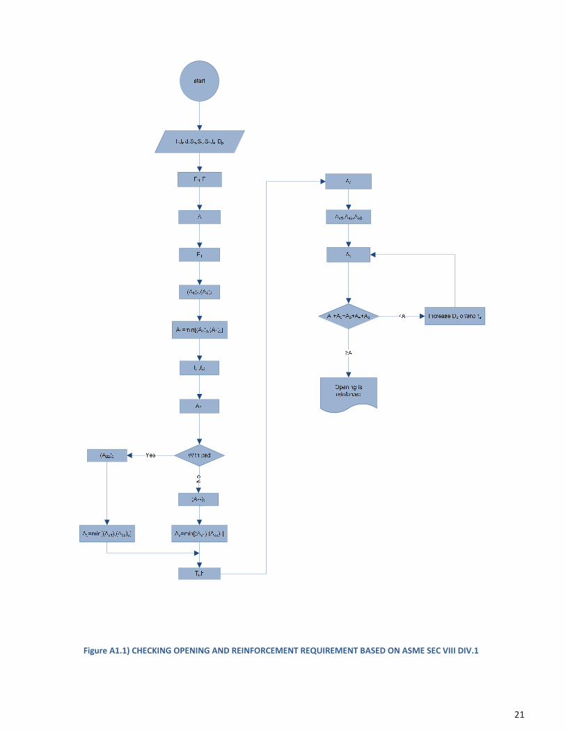
Figure A1.1) CHECKING OPENING AND REINFORCEMENT REQUIREMENT BASED ON ASME SEC VIII DIV.1

22
Figure A1.2) CHECKING OPENING AND REINFORCEMENT REQUIREMENT BASED ON ASME SEC VIII DIV.2

23
APPENDIX 2
EXAMPLE FOR OPENING DESIGN USING PV ELITE
24
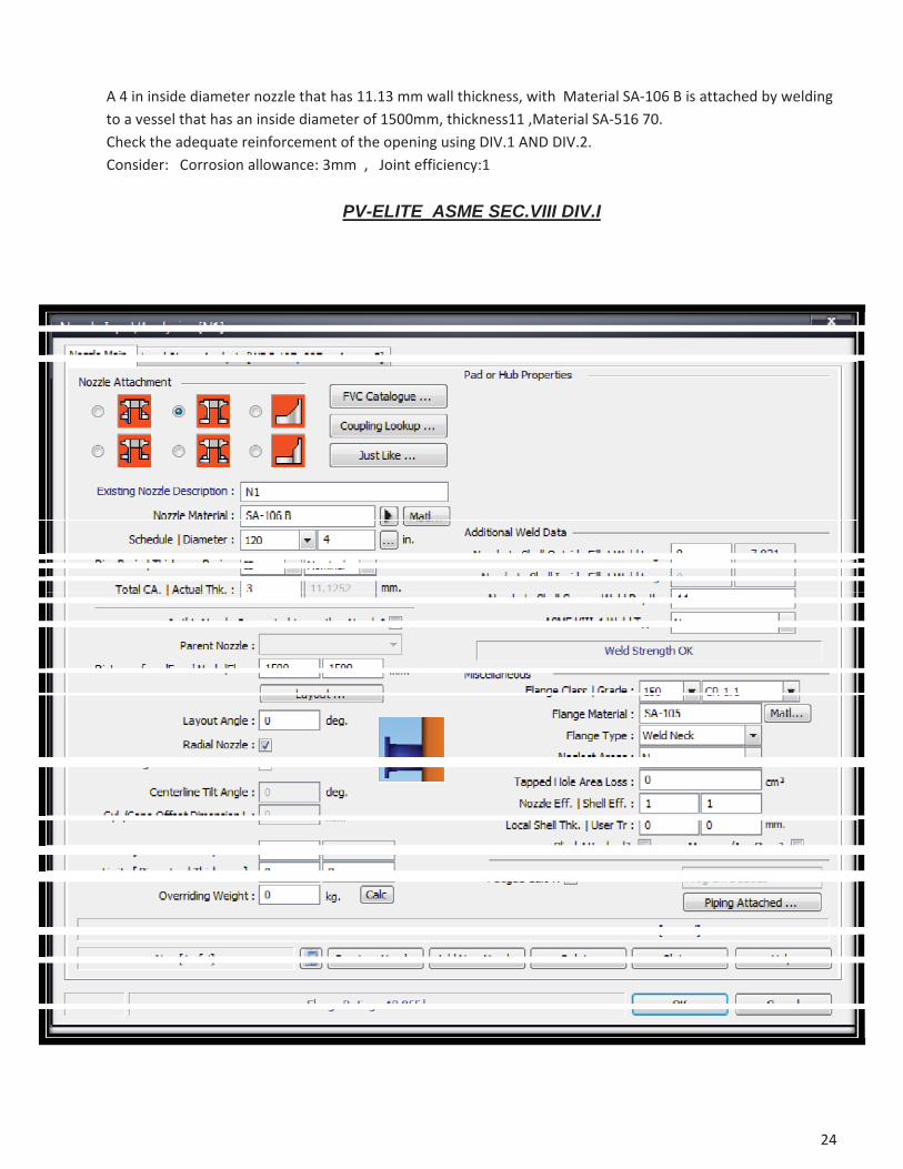
A 4 in inside diameter nozzle that has 11.13 mm wall thickness, with Material SA 106 B is attached by weldingto a vessel that has an inside diameter of 1500mm, thickness11 ,Material SA 516 70.Check the adequate reinforcement of the opening using DIV.1 AND DIV.2.Consider: Corrosion allowance: 3mm , Joint efficiency:1
PV-ELITE_ASME SEC.VIII DIV.I

25

26
PV-ELITE_ASME SEC.VIII DIV.II

27

28

29