Embed Size (px)
Citation preview

EQUIPMENT
Operation Manual
Loctite ® LCA Tubing Adhesive Applicator
98445
FUSE
DISPENSER
MAIN POWER SWITCHPOWER
Ol
Technologies
ITEM NO. 988849
TUBING ADHESIVE APPLICATORITEM NO. 98445
LCA

Table of Contents
1. Please Observe the Following................................................................................................. 3 1.1 Emphasized Sections ...................................................................................................... 3 1.2 For Your Safety............................................................................................................... 3 1.3 Items Supplied ................................................................................................................ 3 1.4 Field of Application (Intended Use) ............................................................................... 4 1.5 Features and Benefits...................................................................................................... 4 2. Description....................................................................................................................... 5 2.1 Description of Unit ......................................................................................................... 5 2.2 Theory of Operation........................................................................................................ 8
3. Technical Data ........................................................................................................................ 8 3.1 Technical Specifications ................................................................................................. 8
4. Setup and Operation................................................................................................................ 9 4.1 Setup ............................................................................................................................... 9
4.1.1 Electrical Connections ............................................................................................ 9 4.1.2 Filling the Reservoir ............................................................................................... 9 4.1.3 Installing of Bushing............................................................................................... 9 4.1.4 Fume Exhaust Housing ......................................................................................... 10 4.1.5 Adjusting the Dispense Flow................................................................................ 10
4.2 Operation...................................................................................................................... 11 4.3 Shut Down .................................................................................................................... 11
5. Care, Cleaning and Routine Inspection ................................................................................ 12 5.1 Cleaning and Dispense Bushing ................................................................................... 12 5.2 Remove the Protective Ring Assembly ........................................................................ 12 5.3 Cleaning the Pumping System...................................................................................... 12
6 Maintenance Repair .............................................................................................................. 16 6.1 Pumping System ........................................................................................................... 16 6.2 How to Replace the Fuses............................................................................................. 16
7. Troubleshooting .................................................................................................................... 16 8. Spare Part amd Accessories List........................................................................................... 17
8.1 Spare Parts .................................................................................................................... 17 8.2 Accessories ................................................................................................................... 17
9. Warranty .......................................................................................................................... 18

1. Please Observe the Following
1.1 Emphasized Sections
Warning! Refers to safety regulations and requires safety measures that protect the operator or other persons from injury. Caution
Emphasizes what must be done or avoided so that the unit or other property is not damaged.
Notice Gives recommendations for better handling of the unit during operation or adjustment as well as for service activities.
1.2 For Your Safety
Ensure that all personnel involved in the installation, operation and maintenance of this machine, as well as those persons who act as supervisory personnel for those listed above, have read and fully understood these instructions before attempting to install, operate or perform maintenance on this machine.
Always wear goggles when dispensing adhesive.
Observe general safety regulations for the handling of chemicals such as Loctite® adhesives and sealants. Observe the manufacturer’s instructions as stated in the Material Safety Data Sheet (MSDS).
While under warranty, the unit may be repaired only by an authorized
Loctite® service representative.
1.3 Items Supplied
Carefully remove the unit from its shipping carton and inspect it for any signs of damage. Any damage should be reported immediately to the carrier. Refer to the list of supplied parts below and compare to the contents. Report any missing parts promptly to the Loctite® customer service department at 1-800-LOCTITE. 1 LCA Tubing Adhesive Applicator 1 Bushing removal pliers 1 Transformer with an ON/OFF switch 1 Line cord 1 "T" hex key 2.5mm 1 Instruction Manual.

1.4 Field of Application (Intended Use) The LCA Tubing Adhesive Applicator is a Light Cure adhesive dispenser that has been designed for precise, repeatable, and quick dispensing of Light Cure adhesive on tubing used for assembling products. The LCA Tubing Adhesive Applicator can dispense adhesive on the external surfaces of tubing, conical surfaces, needles, and various types of connectors and components.
1.5 Features and Benefits
• Easier and faster dispensing than other traditional methods or procedures for dispensing adhesive 360°. Adhesive is applied by simply inserting a tube or component into the bushing and immediately pulling it back for assembly operation. It is not necessary to wait or rotate the part inside the bushing.
• Reproducible bonding: when a tube (or component) is pushed into the bushing, a fixed stop determines the right dispensing length. A film of adhesive is accurately and uniformly dispensed to form a 360° band all around the surface of the tubing (or component).
• Operator training is minimal: the dispensing systems guarantee reproducible adhesive quantities and failure-proof adhesive.
• Optimal protection against light in order to prevent unwanted polymerization of U.V. adhesive inside the dispenser.
• This system is equipped with a protective ring that encloses the dispensing area. This allows for fume removal using optimal exhaust hosing and customer supplied ventilation, and prevents light exposure of the adhesive when the dispenser is not in use.
• Application rate adjustment: by simple rotating the knob, it is possible to increase or decrease the amount of the adhesive applied.
• Easy and simple cleaning and maintenance. • Safe, noiseless and practical configuration: power supply from the
transformer to the dispenser is low voltage. • Benchtop configuration gives the user the ability to quickly and easily move
the adhesive dispenser to wherever it is needed. • No compressed air needed.

2. Description 2.1 Description of Unit
Figure 1 – LCA Tubing Adhesive Applicator 98445
Item Description Item Description Item Description
1 ON/OFF switch 7 Pumping system base 13 Reservior cap
2 Indicator Light - Green LED
8 Fume exhaust manifold 14 Exhaust tube adapter
(optional accessory)
3 Fuse holder 9 Dispensing bushing 15 Exhaust tubing
(optional accessory)
4 Interface cable connector 10 Protective ring 16 Motor Assembly
5 Transformer 11 Screws, motor 17 Interface cable
6 Adhesive level indicator 12 Flow control knob
8
1
MAIN POWER SWITCH4
23
FUSE
DISPENSER
POWER
ITEM NO. 988849
Technologies
l O
7
15
12
9
TUBING ADHESIVE APPLICATOR
17
5
11
6ITEM NO. 98445
LCA
10
16
13
14
Figure 1
Fig. 2 Figure 2 – Transformer power modular. 1 Fig 2 – Main power modular 2 Fig 2 – 115/230V power switch
3 Fig 3 – Fuse
1
2
A
B3
Fig. 3
Figure 3 – Pumping system/level indicator 1 Fig 3 – Adhesive level indicator
A. Maximum level B. Minimum level
2 Fig 3 – Knob for clamping exhaust removal system 3 Fig 3 – Screw to secure electric motor

1
2
3
4
Fig. 4
Figure 4 – Pumping System, Top View 1 Fig 4 – Reservoir Inlet 2 Fig 4 – Adhesive Flow Adjustment Knob
3 Fig 4 – Reservoir Cap 4 Fig 4 – Flow Control Range
1
2
3
Fig. 5
Figure 5 – Pumping System, Front Side
1 Fig 5 – The dispensing bushing fastening screws 2 Fig 5 – Electric motor mounting screw.
3 Fig 5 – Electric motor group

2.2 Theory of Operation The LCA Tubing Adhesive Applicator 98445 consists of an adhesive deliver system, tube bushing, with a remote power transformer. The adhesive delivery system is connected to the power supply by a solvent resistant 18-volt interface cable. The adhesive delivery system consists of an electric motor mounted on a 30ml reservoir that houses a submersible pump. A fine exhaust manifold encloses the reservoir and allows for adhesive vapors to be transported through an exhaust tube to air handling system (sold separately). The adhesive is continuously circulated through the dispense bushing by means of the electric pumping system. Adhesive and carefully and precisely dispensed on medical tubing and components through a custom made dispense bushing. The tubing or component is inserted into the bushing and immediately removed. This action allows adhesive to flow onto the part applying a consist film of adhesive for a given length and preparing the part for the assembly operation. A flow control knob, located at the top of the pumping system, regulates the amount of adhesive. The dispense bushing is the “heart” of the dispenser, and can dispense adhesive on the external surface of tubing and components surfaces from 2.0 to 6.0 mm in diameter. Each diameter of tubing requires its own dispensing bushing. Bushings are easily and quickly interchangeable. Standard maximum dispensing length is 8 mm. Dispense bushing for non-standard dispensing lengths are available upon request.
3. Technical Data
3.1 Technical Specifications
Electric supply to transformer AC 115/230V – 50/60Hz Electrical supply to dispenser AC 18V – 10VA Protection to transformer 2 – 5mm x 20mm 1 A fuses Protection to dispenser 1 – 5 mm x 20mm fuse of T0500mA (delayed action) Regulatory CE Construction materials Dispense Bushings stainless steel Pumping System anodized aluminum, acetal resin (Delrin®) and PTFE (Teflon®) Transformer ext. dimensions 125 x 55 x 90 mm [5 x 2.2 x 3.6 in.] Pumping System ext. dimensions 225 x 140 mm dia. [9 x 5.5] Transformer weight 0.55 Kg [1.25 lb.] Dispenser weight 3.5 Kg [7.7 lb.] Maximum viscosity of adhesive 1500 cP [1500 mPas]

4. Setup and Operation
4.1 Setup
• The LCA Tubing Adhesive Applicator is designed for clean room use. The dispenser must be used in an environment suitable for the Light Cure Adhesive. Refer to the adhesive technical data sheet.
• Dust or excess moisture in the working environment can affect the dispenser operation.
• The dispenser has to be placed on a flat surface. Tilting the dispenser when in operation may cause adhesive to spill.
4.1.1 Electrical Connections
• Connect interface cable from pumping system to transformer. • Insure that the power switch, located on the transformer is in the OFF
position. • Connect line cord to transformer. • Connect line cord to main electrical supply.
4.1.2 Filling the Reservoir
• Turn the transformer power switch to the ON position [1 Fig. 1] • Remove the reservoir cap. [3 Fig. 4] • Use a syringe to fill the reservoir with adhesive [1 Fig. 4] Do not
exceed the maximum level indicator. [A Fig. 3]
NOTE: At the first dispenser start-up, and after each complete cleaning, it may be necessary to rotate the dispenser body 45°, 2 or 3 times, so as to let the air go out from the dispensing system.
NOTE: The internal capacity of the dispenser is 30ml. This corresponds to the max. level indicator. [A Fig. 3] 4.1.3 Installing of Bushing
NOTE: Each diameter range of tube or component requires its own bushing.
Warning! Switch OFF the dispenser, by means of transformer POWER SWITCH [2 Fig. 2]
• Rotate the protective ring until the big hole [B Fig. 7] is in line with the bushing.
• Remove fastening screws from the dispensing bushing [1 Fig. 5]

• Remove the dispensing bushing from its housings, using the tool provided [Fig. 6].
• Put the required bushing into the housing paying attention that the little notch is positioned as shown in 1 Fig. 6. Now push and rotate clockwise the bushing until the small pin [2 Fig. 6] goes into its housing; then push the bushing until it dead ends. Make sure that the two marks [3 Fig. 6] are vertically aligned.
• Put the screws fixing the bushing [1 Fig. 5] back in place.
1
2
3
Fig 6
4.1.4 Fume Exhaust Housing
The dispenser is also equipped with an exhaust housing that allows ventilation of the equipment.
• Connect optional exhaust hose from the clean air room system to the
adapter [15 Fig. 1]. • Connect the adapter to the exhaust port on the rear side of the pumping
system [14 Fig. 1].
4.1.5 Adjusting the Dispense Flow It is impossible to increase or decrease the flow of adhesive being dispensed by the bushing, rotating the knob [2 Fig. 4] from 0° to 90°, as shown in 4 Fig. 4. Rotate the knob clockwise to increase the quantity of adhesive in the
bushing. Rotate the knob counterclockwise to decrease the quantity of
adhesive in the bushing.

4.2 Operation
• The LCA Tubing Adhesive Applicator is ready to be used. • To dispense the adhesive, insert the tubing or component into the dispense
bushing until it stops, and immediately pull it back for an assembly operation.
NOTE: Usually, it is not necessary to rotate the tube or component into the bushing; but if this should happen, it will not affect the adhesive dispensing quality. • During use, the adhesive level in the dispenser body will decrease. Fill the
reservoir with adhesive before the minimum level [B Fig. 3] is reached.
4.3 Shut Down For Short Breaks • It is always possible to stop the work cycle. After pulling back the last piece
from the dispensing bushing rotating the protective ring until the bushing is no longer visible.
NOTE: For short breaks, it is advisable to cover the dispense bushing, so as
to keep the adhesive protected from light. End of Work Day • Let the adhesive flow freely in the
dispensing bushings for a few seconds.
BA
1
(working position) (maintenance position) Fig.7
• Turn off the dispenser by placing the POWER SWITCH of the transformer in the OFF position.
• Make sure the adhesive in not at the minimum level. Top off reservoir with adhesive.
• Close the dispense bushing zone by rotating the protective ring until the bushing is no longer visible, so as to keep the adhesive protected from light.
Figure 7 – Pumping System with protective ring 1 Fig 7 – Protective Ring A Fig 7 – Working position B Fig 7 – Maintenance position
5. Care, Cleaning and Routine Inspection
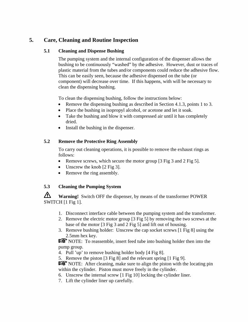
5.1 Cleaning and Dispense Bushing The pumping system and the internal configuration of the dispenser allows the bushing to be continuously “washed” by the adhesive. However, dust or traces of plastic material from the tubes and/or components could reduce the adhesive flow. This can be easily seen, because the adhesive dispensed on the tube (or component) will decrease over time. If this happens, with will be necessary to clean the dispensing bushing. To clean the dispensing bushing, follow the instructions below: • Remove the dispensing bushing as described in Section 4.1.3, points 1 to 3. • Place the bushing in isopropyl alcohol, or acetone and let it soak. • Take the bushing and blow it with compressed air until it has completely
dried. • Install the bushing in the dispenser.
5.2 Remove the Protective Ring Assembly To carry out cleaning operations, it is possible to remove the exhaust rings as follows: • Remove screws, which secure the motor group [3 Fig 3 and 2 Fig 5]. • Unscrew the knob [2 Fig 3]. • Remove the ring assembly.
5.3 Cleaning the Pumping System
Warning! Switch OFF the dispenser, by means of the transformer POWER SWITCH [1 Fig 1].
1. Disconnect interface cable between the pumping system and the transformer. 2. Remove the electric motor group [3 Fig 5] by removing the two screws at the
base of the motor [3 Fig 3 and 2 Fig 5] and lift out of housing. 3. Remove bushing holder: Unscrew the cap socket screws [1 Fig 8] using the
2.5mm hex key. NOTE: To reassemble, insert feed tube into bushing holder then into the
pump group. 4. Pull ’up’ to remove bushing holder body [4 Fig 8]. 5. Remove the piston [3 Fig 8] and the relevant spring [1 Fig 9].
NOTE: After cleaning, make sure to align the piston with the locating pin within the cylinder. Piston must move freely in the cylinder. 6. Unscrew the internal screw [1 Fig 10] locking the cylinder liner. 7. Lift the cylinder liner up carefully.
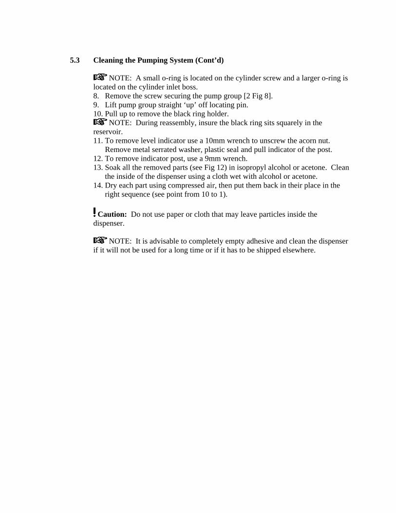
5.3 Cleaning the Pumping System (Cont’d)
NOTE: A small o-ring is located on the cylinder screw and a larger o-ring is located on the cylinder inlet boss. 8. Remove the screw securing the pump group [2 Fig 8]. 9. Lift pump group straight ‘up’ off locating pin. 10. Pull up to remove the black ring holder.
NOTE: During reassembly, insure the black ring sits squarely in the reservoir. 11. To remove level indicator use a 10mm wrench to unscrew the acorn nut.
Remove metal serrated washer, plastic seal and pull indicator of the post. 12. To remove indicator post, use a 9mm wrench. 13. Soak all the removed parts (see Fig 12) in isopropyl alcohol or acetone. Clean
the inside of the dispenser using a cloth wet with alcohol or acetone. 14. Dry each part using compressed air, then put them back in their place in the
right sequence (see point from 10 to 1).
Caution: Do not use paper or cloth that may leave particles inside the dispenser.
NOTE: It is advisable to completely empty adhesive and clean the dispenser
if it will not be used for a long time or if it has to be shipped elsewhere.

1
2
3
4
Fig. 8
Figure 8 – Pumping System, Internal 1 Fig 8 – Bushing holder mounting screws 2 Fig 8 – Pump Assembly 3 Fig 8 – Piston Assembly 4 Fig 8 – Bushing holder body
1
Figure 9 – Pumping System, Spring 1 Fig 9 – Spring
2
1
Figure 10 - Pumping System, Cylinder Liner 1 Fig 10 – Screw 2 Fig 10 – Cylinder liner

1
Fig. 11 Figure 11 – Pump Removal 1 Fig 11 – Mounting screw for pump
Bush
Bushholder
Pump Cylinderliner
Spring
Piston
Fig. 12 Figure 12 – Pumping System Components

6 Maintenance Repair
6.1 Pumping System The pumping system inside the dispenser has been made with materials that are resistant to wear. If the pumping action should be sufficient or if there is no pumping, remove the dispense bushing and clean it as described in Section 5. If the problem is not solved, clean the entire dispenser in Section 5.3.
6.2 How to Replace the Fuses If the fuses have burned out, open the fuse holder (3 Fig 2) and replace them with 2, 1 A fuses.
7. Troubleshooting
Problem Possible Cause Correction
No adhesive is dispensed. • No power to unit
• Power switch is in Off position
• Product reservoir is empty.
• Piston and cylinder improperly installed
• Check valve may be locked up
• Motor is not working
• Plug unit to main power source
• Move power switch to ON
• Fill product resevoir
• Align the piston and cylinder.The pin in the cylinder must act as the piston’s guide.
• Clean pump assembly
• Check both fuses [3 Fig. 1 and 3 Fig. 2]
Insufficent Adhesive • Flow control is set to minmum
• Bushing is clogged
• Pump is clogged
• Increase flow control setting
• Clean dispense bushing
• Clean pumping system
Too Much Adhesive • Flow control is set to maximum
• Bushing may be over sized
• Decrease flow control setting
• Replace bushing

8. Spare Part amd Accessories List
8.1 Spare Parts
Figure Description Part No. Fig. 12 Pump Assembly Kit
• Pump Assembly • Feed tube • Mounting screw
988850
Fig. 12 Cylinder / Piston Assembly Kit • Cylinder Assembly • Piston Assembly • Spring • Spring cap • Two o-rings • Mount screw
988851
Fig. 12 Bushing Holder with mounting screws 988852 16 Fig. 1 Motor Assembly – 24 Volt motor with drive shaft 988853 1 Fig. 1 Line cord 983680 5 Fig. 1 Transformer 988849
8.2 Accessories
Description Part No. 2mm Bushing 989038 3mm Bushing 989039 4mm Bushing 989040 5mm Bushing 989041 6mm Bushing 989042 15 feet of exhaust tubing with end cuffs 988854 Bushing Removal Pliers 989377 2.5mm Hex Key 989376
Henkel Loctite can supply custom made dispensing bushing manufactured according to customer tubing or components specifications.

9. Warranty
Henkel expressly warrants that all products referred to in this Instruction Manual for (98445 Henkel Loctite® LCA Tubing Adhesive Applicator) (hereafter called “Products”) shall be free from defects in materials and workmanship. Liability for Henkel shall be limited, as its option, to replacing those Products which are shown to be defective in either materials or workmanship or to credit the purchaser the amount of the purchase price thereof (plus freight and insurance charges paid therefor by the user). The purchaser’s sole and exclusive remedy for breach of warranty shall be such replacement or credit. A claim of defect in materials or workmanship in any Products shall be allowed only when it is submitted in writing within one month after discovery of the defect or after the time the defect should reasonably have been discovered and in any event, within (12) months after the delivery of the Products to the purchaser. This warranty does not apply to perishable items, such as (fuses). No such claim shall be allowed in respect of products which have been neglected or improperly stored, transported, handled, installed, connected, operated, used or maintained. In the event of unauthorized modification of the Products including, where products, parts or attachments for use in connection with the Products are available from Henkel, the use of products, parts or attachments which are not manufactured by Henkel, no claim shall be allowed. No Products shall be returned to Henkel for any reason without prior written approval from Henkel. Products shall be returned freight prepaid, in accordance with instructions from Henkel. NO WARRANTY IS EXTENDED TO ANY EQUIPMENT WHICH HAS BEEN ALTERED, MISUSED, NEGLECTED, OR DAMAGED BY ACCIDENT, OR IF THE SYSTEM WAS USED TO DISPENSE ANY LIQUID MATERIAL OTHER THAN LOCTITE® PRODUCTS. EXCEPT FOR THE EXPRESS WARRANTY CONTAINED IN THIS SECTION, HENKEL MAKES NO WARRANTY OF ANY KIND WHATSOEVER, EXPRESS OR IMPLIED, WITH RESPECT TO THE PRODUCTS. ALL WARRANTIES OF MERCHANTABILITY, FITNESS FOR A PARTICULAR PURPOSE, AND OTHER WARRANTIES OF WHATEVER KIND (INCLUDING AGAINST PATENT OR TRADEMARK INFRINGEMENT) ARE HEREBY DISCLAIMED BY HENKEL AND WAIVED BY THE PURCHASER. THIS SECTION SETS FORTH EXCLUSIVELY ALL OF LIABILITY FOR HENKEL TO THE PURCHASER IN CONTRACT, IN TORT OR OTHERWISE IN THE EVENT OF DEFECTIVE PRODUCTS. WITHOUT LIMITATION OF THE FOREGOING, TO THE FULLEST EXTENT POSSIBLE UNDER APPLICABLE LAWS, HENKEL EXPRESSLY DISCLAIMS ANY LIABILITY WHATSOEVER FOR ANY DAMAGES INCURRED DIRECTLY OR INDIRECTLY IN CONNECTION WITH THE SALE OR USE OF, OR OTHERWISE IN CONNECTION WITH, THE PRODUCTS, INCLUDING, WITHOUT LIMITATION, LOSS OF PROFITS AND SPECIAL, INDIRECT OR CONSEQUENTIAL DAMAGES, WHETHER CAUSED BY NEGLIGENCE FROM HENKEL OR OTHERWISE. Henkel Corporation 1001 Trout Brook Crossing Rocky Hill, CT 06067-3910
Henkel Canada Corporation 2225 Meadowpine Boulevard Mississauga, Ontario L5N 7P2
Henkel Capital, S.A. de C.V. Calzada de la Viga s/n Fracc. Los Laureles Loc. Tulpetlac, C.P. 55090 Ecatepac de Morelos, Edo. de México
Henkel Automotive Technology Center 2455 Featherstone Road Auburn Hills, Michigan 48326
Henkel Ltda. Rua Karl Huller, 136 – Jd. Canhema 09941-410 Diadema/SP, Brazil
www.loctite.com
Loctite is a trademark of Henkel Corporation, U.S.A. © Copyright 2004. Henkel Corporation All rights reserved. Data in this operation manual is subject to change without notice. Manual P/N: 988855, Rev B, Date: 05/2005