Embed Size (px)
Citation preview

Page 1 / 13
EQUIPMENTS FOR THE WELDING OF UPPER CUP OF
GAS CYLINDER

Page 2 / 13
1. PREAMBULE :
This document is strictly confidential and may not be disclosed or duplicated without prior
per issio of ALW. This do u e t is ased o the i for atio ’s re eived a d is o l relative to this project.
The photographs are only for information and explanation and cannot be contractual.
2. SCOPE OF THIS OFFER :
This offer is made on information supplied to us as follows:
Job: Continuous circular welding of neck on the upper half on domestic gas bottle
Process: Submerged Arc process
Preparation: Under customer responsibilities
Welding result: No engagement and no responsibilities for the welded final results and
fi al produ t ho ologatio . It’s u der usto er responsibilities.
Upper half bottle: Diameter = 300 mm
Length = 266,5 mm
Thickness = 3,3 mm
Based on it, our proposal is based on the supply of a complete welding machine comprising of:
A standard machine with platform and components,
A work piece tooling device,
A Subarc 5 SAW welding system.
This offer includes the commissioning in our factory, a technical and electrical technical files (
3 copies in English languages )
Page 3 / 13
3. PREPARATION AND PART TO WELD :

Page 4 / 13

Page 5 / 13
4. WELDING CYCLE:
1. Manual loading of the work pieces by operator,
2. Manual positioning of the articulated support,
3. Action on pushbutton :clamping of work pieces,
4. Manual preparation of the torch position and welding conditions (wire cut, flu …),
5. Action on welding start pushbutton (ON) :
arc striking,
work pieces rotation: 360° rotation + overlap,
6. Automatic stopping of welding and work piece movement in case of normal cycle [or
manual action on welding stop pushbutton (OFF)],
7. Action on pushbutton : unclamping of work pieces,
8. Manual evacuation of the articulated support,
9. Manual unloading of work piece by operator.
The above cycle operations are provided for information only and may vary according to:
- cleanliness of work piece,
- quality of preparation,
- position of torch,
- consumables : wire and flux used,
- …

Offre 11050_01 Page 6 / 13
Details of loading and positioning of work pieces:
5 / rotation of the tooling
2 / Bottle half part : positioned
over the upper cup. 1 / Upper cup: positioned in
the index punching tool.

Page 7 / 13

Page 8 / 13
Rep 6
Rep 5
Rep 3
Rep 4
Rep 1
Rep 2
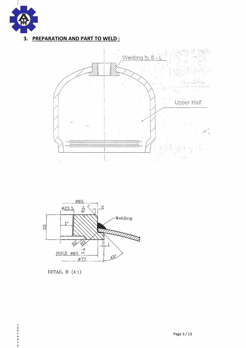
5. EQUIPMENTS DESCRIPTION:
We propose a configuration of standard equipments specifically assembled for your application
and consisting of the principal elements describe in the following pages.
A platform concept integrates all the necessary elements. This design facilitates fast and easy
installation on site and the easy relocation at a later date if required.
A robust mechanical structure (rep 1) supports all the equipments as the welding head…
A tooling unit (rep 2) with a rotating plate and a special tooling device.
The tooling device include the necessary for positioning and centring the two parts (neck
and upper half bottle) and to guarantee a high production rate.
The motorised unit is integrated into the mechanical welded structure, protected from
impacts and dust.
An articulated support (rep 3) supporting the welding head and pivoting to clear space for the
loading and unloading of the work piece.
Axis pivot: for manual pivoting

Page 9 / 13
A mono SAW welding head (rep 4), including mainly:
A single torch,
Wire feeding unit,
Flux distribution,
Two manual slides (travel = 60mm) for the vertical and transversal adjustment
of the torch in the joint.

Page 10 / 13
A control and electrical panel (rep 5) regroups the electrical and pneumatic components;
these are in a protected and ventilated box, protected from the shocks and dust.
A control panel (Rep5) including our Gyrmatic modular systeme
A welding remote control (rep 6) with emergency stop and for start and stop the welding
cycle.

Page 11 / 13
6. WELDING EQUIPMENTS: SUBARC 5
Welding control unit box
arc voltage display and welding current display
arc voltage and wire feed adjustment with single turn potentiometer
controls of the welding cycle
pre-setting and pre-selection of the welding current and voltage parameters
Devimatic DX7 wire feed unit
A tachometer driven by the wire feed motor guarantees very accurate
welding control.
A simple and rugged mechanical assembly that is easy to configure to
suit your application.
Fine adjustments for all degrees of freedom in rotation allow easy adjustment of the point at
which the wire impinges on the work piece.
Base equipment: linear speed of wire feed between 0,17 to 4,2 m/min,
Single wire configuration for wire size = 2,4 mm ( other wire diameter are available )
Flux recovery equipment with hopper (10 l) and manual flux supply valve
This is a compact, self-contained unit that ensures the recovery and supply of the
welding protection flux. Considerably reduces manual flux tank refilling operations. This
is fitted with a powerful "VENTURI" with compressed air supply tap and a cloth sleeve
breather in the tank cover.
It receives compressed air at the network pressure.

Page 12 / 13
Power source: 1003 DC => 650DC
Rugged, reliable, proof against aggressive industrial environments,
Fan cooled, fitted with thermal cut-out, easy to move using crane or forklift,
Electronic protection against overload
Quick connection to the core of the installation by simple and accessible connectors
Remote controlled.
1000 A / 44V duty cycle at 100 %
400/ 440V - 50/60 Hz - 3 phases
Technology: Thyristors
Primary current at 100% duty cycle: 95 A
Maximum power consumption : 65,8 Kva
Temperature range : 0-40°C
Protection index : IP23
Insulation class : H
7. ENVIRONNEMENT CONDITIONS
Standards and Regulations
Our machines are studied and manufactured in accordance with the European standards and
regulations. As these equipments will integrate with other equipments, ALWF provide only a
declaration of incorporation EC. The customer is responsible for the CE certification.
Operation conditions for the electric cabinet ( control panel )
Ambient temperature range: 15 ~ 50°C max.
Ambient humidity range: 20 ~ 80 % HR max.
No condensation
No dust
Electrical supply
The electrical connections of any nature outside the machine and the main power to the
machine are not our supplying.
The characteristics of the main power to supply are:
Voltage: 3 phases 300 V + ground connection
Frequency: 50 Hz
Estimate power supply: ≈ to be confirm latter
Fluid supply
The fluid connections of any nature outside the machine and the supplying with pressure
reducing stations to the machine are not our supplying.

Page 13 / 13
4 OTHER COMMERCIAL CONDITIONS
Delivery time
4/6 Months ex works France or Italy from receipt of down payment and valid purchasing
order .Exact delivery will be confirmed on receipt of order

Page 1 / 11
EQUIPMENTS FOR THE SAW CIRCULAR WELDING OF
GAS CYLINDER BOTTLE

Page 2 / 11
1. PREAMBULE :
This document is strictly confidential and may not be disclosed or duplicated without prior
per issio of ALW. This do u e t is ased o the i for atio ’s re eived a d is o l relative to this project.
The photographs are only for information and explanation and cannot be contractual.
2. SCOPE OF THIS OFFER :
This offer is made on information supplied to us as follows:
Job: Continuous circular welding of the half and the bottom parts on domestic gas bottle
Process: Submerged Arc process
Preparation: Under customer responsibilities
Welding result: No engagement and no responsibilities for the welded final results and
fi al produ t ho ologatio . It’s u der usto er responsibilities.
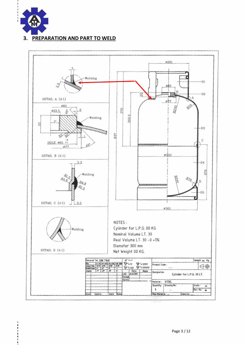
Upper half bottle: Diameter = 300 mm
Length = 637 mm
Thickness = 3,3 mm
Based on it, our proposal is based on the supply of a complete welding machine comprising of:
A standard machine with platform and components,
A work piece tooling device,
Two Subarc 5 SAW welding systems.
This offer includes the commissioning in our factory, a technical and electrical technical file (
3 copies in English language )

Page 3 / 11

Page 4 / 11
3. PREPARATION AND PART TO WELD :

Page 5 / 11

Page 6 / 11
4. WELDING CYCLE:
1. Manual loading of the work pieces by operator,
2. Action on pushbutton : clamping of work pieces,
3. Manual preparation of the torches positions and welding conditions (wire cut, flu …),
4. Action on welding start pushbutton (ON) :
4.1. arc striking,
4.2. work pieces rotation: 360° rotation + overlap,
4.3. the torch n°2 (for the bottom piece) stops,
4.4. work pieces rotation: a second 360° rotation + overlap, (for the 2nd passes)
5. Automatic stopping of welding and work piece movement in case of normal cycle [or manual
action on welding stop pushbutton (OFF)],
6. Action on pushbutton : unclamping of work pieces,
7. Manual unloading of work piece by operator.
The above cycle operations are provided for information only and may vary according to:
- cleanliness of work piece,
- quality of preparation,
- position of torch,
- consumables : wire and flux used,
- …

Page 7 / 11
Details of loading and positioning of work pieces:
Page 8 / 11
Rep 4
Rep 5
Rep 6
Rep 7 Rep 2
Rep 3
5. EQUIPMENTS DESCRIPTION:
We propose a configuration of standard equipments specifically assembled for your application
and consisting of the principal elements describe in the following pages.
A platform concept integrates all the necessary elements. This design facilitates fast and easy
installation on site and the easy relocation at a later date if required.
A robust mechanical structure (rep 1) supports all the equipments as the welding head…
A motorised rotation unit (rep 2) with a rotating plate (Ø400mm) equipped with devices for
positioning and centring the handle.
The motorised unit is integrated into the mechanical welded structure, protected from
impacts and dust (ie: rotating speed: 0.3 to 8.5 rpm).
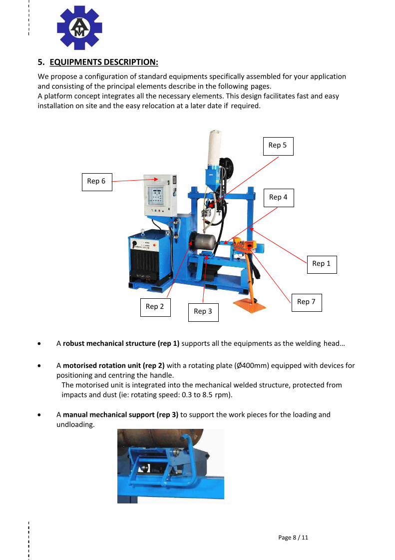
A manual mechanical support (rep 3) to support the work pieces for the loading and
undloading.
Rep 1

Page 9 / 11
A pneumatic tailstock (rep 4) with dead centre equipped with a flow limiter enabling
adjustment of the forward or reverse speed translation and a stop cylinder safety device
blocking the dead centre in the position which it occupies in case of accidental cut off the
compressed air supply.
Two mono SAW welding head (rep 5), including mainly:
A single torch,
Wire feeding unit,
Flux distribution,
Two manual slides (travel = 60mm) for the vertical and
transversal adjustment of the torch in the joint.
A control and electrical panel (rep 6) including our Gyrmatic modular system:
A welding remote control (rep 7) with emergency stop and for start
and stop the welding cycle.
Free rotate turntable (Ø400mm) equipped with
simple devices for the position of bottom part.
Tailstock position adjustment
Pneumatic travel: 100 mm

Offre 11052_01 Page 10 / 11
6. WELDING EQUIPMENTS: 2 x Subarc 5 system
Welding control unit box
arc voltage display and welding current display
arc voltage and wire feed adjustment with single turn potentiometer
controls of the welding cycle
pre-setting and pre-selection of the welding current and voltage parameters
Devimatic DX7 wire feed unit
A tachometer driven by the wire feed motor guarantees very accurate
welding control.
A simple and rugged mechanical assembly that is easy to configure to
suit your application.
Fine adjustments for all degrees of freedom in rotation allow easy adjustment of the point at
which the wire impinges on the work piece.
Base equipment: linear speed of wire feed between 0,17 to 4,2 m/min,
Single wire configuration for wire size = 2,4 mm
Flux recovery equipment with hopper (10 l) and manual flux supply valve
This is a compact, self-contained unit that ensures the recovery and supply of the
welding protection flux. Considerably reduces manual flux tank refilling operations.
This is fitted with a powerful "VENTURI" with compressed air supply tap and a cloth
sleeve breather in the tank cover.
It receives compressed air at the network pressure.
Power source: 1003 DC => 650DC
Rugged, reliable, proof against aggressive industrial environments,
Fan cooled, fitted with thermal cut-out, easy to move using crane or forklift,
Electronic protection against overload
Quick connection to the core of the installation by simple and accessible connectors
Remote controlled.
1000 A / 44V duty cycle at 100 %
400/ 440V - 50/60 Hz - 3 phases
Technology: Thyristors
Primary current at 100% duty cycle: 95 A
Maximum power consumption : 65,8 kVA
Temperature range : 0-40°C.
Protection index : IP23
Insulation class : H

ATM Deutschland GmbH Page 11 / 11
7. ENVIRONNEMENT CONDITIONS
Standards and Regulations
Our machines are studied and manufactured in accordance with the European standards and
regulations. As these equipments will integrate with other equipments, ALWF provide only a
declaration of incorporation EC. The customer is responsible for the CE certification.
Operation conditions for the electric cabinet ( control panel )
Ambient temperature range: 15 ~ 50°C max.
Ambient humidity range: 20 ~ 80 % HR max.
No condensation
No dust
Electrical supply
The electrical connections of any nature outside the machine and the main power to the
machine are not our supplying.
The characteristics of the main power to supply are:
Voltage: 3 phases 380 V + ground connection
Frequency: 50 Hz
Estimate power supply: ≈ to be confirm latter
Fluid supply
The fluid connections of any nature outside the machine and the supplying with pressure
reducing stations to the machine are not our supplying.

Page 1 / 12
EQUIPMENTS FOR HANDLE MIG WELDING
OF GAS CYLINDER BOTTLE

Page 2 / 12
1. PREAMBULE
This document is strictly confidential and may not be disclosed or duplicated without prior
per issio of ALW. This do u e t is ased o the i for atio ’s re ei ed a d is o ly relati e to this project.
The photographs are only for information and explanation and cannot be contractual.
2. SCOPE OF THIS OFFER
This offer is made on information supplied to us as follows:
Job: Discontinuous circular welding of the handle on the upper half gas bottle
Process: MIG process
Preparation: under customer responsibilities
Welding result: No engagement and no responsibilities for the welded final results and
fi al produ t ho ologatio . It’s u der usto er responsibilities.
Upper half bottle : Diameter = 300 mm
Length = 370 mm
Thickness = 3,3 mm
Based on it, our proposal is based on the supply of a complete welding machine comprising of:
A standard machine with platform and components,
A work piece tooling device,
A MIG welding systems.
This offer includes the commissioning in our factory, a technical and electrical technical file (
3 copies in English language ).
Page 3 / 12
3. PREPARATION AND PART TO WELD

Page 4 / 12
4. WELDING CYCLE
1. Manual loading of the work pieces by operator,
2. Action on pushbutton (located on the tailstock) : In contact positioning of piece through
advance of pneumatic tailstock,
3. A tio o y le start up push utto :
Lowering of the torch,
Work piece circular movement start up,
Arc striking (temporisation after circular movement),
Welding of the programmed sequence (3 or 4 welds),
work pieces rotation: 360° rotation + overlap (adjustable)
automatic stopping of welding,
automatic stopping work piece movement when return to origin,
Raising of welding torch.
4. Action on unclamping pushbutton : unclamping of work piece by reversing of the
pneumatic tailstock,
5. Manual unloading of work piece by operator
The above cycle operations are provided for information only and may vary according to:
- cleanliness of work piece,
- quality of preparation,
- position of torch,
- consumables : wire and flux used,
- …
Page 5 / 12
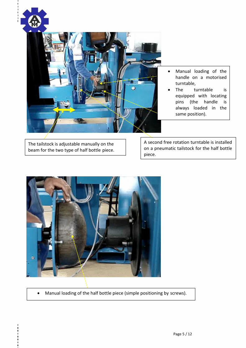
Manual loading of the
handle on a motorised
turntable,
The turntable is
equipped with locating
pins (the handle is
always loaded in the
same position).
A second free rotation turntable is installed
on a pneumatic tailstock for the half bottle
piece.
The tailstock is adjustable manually on the
beam for the two type of half bottle piece.
Manual loading of the half bottle piece (simple positioning by screws).

Page 6 / 12
The quality of the join to
weld is done by the quality
of fabrication of the
pieces.
In contact positioning of the half bottle and handle by tailstock translation.
Pieces in rotation,
Torch in lowered position, ready to weld.

Page 7 / 12
Welded joints

Page 8 / 12
5. EQUIPMENTS DESCRIPTION
( HORIZONTAL WELDING POSITION RECOMMENDED BY ALW )
We propose a configuration of standard equipments specifically assembled for your application
and consisting of the principal elements describe in the following pages.
A platform concept integrates all the necessary elements. This design facilitates fast and easy
installation on site and the easy relocation at a later date if required.
Rep 5 Rep 1
Rep 4
Rep 6
Rep 2 Rep 3
PICTURE SHOWES MACHINE IN HORIZONTAL WELDING POSITION
A robust mechanical structure (rep 1) supports all the equipments, as the welding head …
A motorised rotation unit (rep 2) with plate (Ø400mm) and tooling allowing the centring of
the handle work piece. The motorised unit is integrated into the mechanical structure,
protected from impacts, dust and spatter (ie: rotating speed: 0.3 to 8.5 rpm).
A pneumatic tailstock (rep 3) with dead centre equipped with a flow limiter enabling
adjustment of the forward or reverse speed translation and a stop cylinder safety device
blocking the dead centre in the position which it occupies in case of accidental cut off the
compressed air supply.

Page 9 / 12
A control panel (Rep4) including our Gyrmatic modular system :
A torch pneumatic slide (travel 100mm) (Rep 5) for the execution of the welding cycle and
include also manual slides for the vertical and horizontal adjustment of the torch in the joint
(travel 50mm).
A protective screen (Rep 6) : to protect the operator from light radiations
A welding control box ith e erge y stop a d start a d stop
push utto s for the eldi g cycle.
Free rotate turntable (Ø400mm) equipped with simple
devices for the position of half bottle.
Tailstock position adjustment
Pneumatic travel: 100 mm

Page 10 / 12
6. WELDING EQUIPMENTS : MIG MAG PROCESS
TO BE DEFINE BETWEEN CITOMIG, CITOPULS AND CITOWAVE

Page 11 / 12
8. ENVIRONNEMENT CONDITIONS
Standards and Regulations
Our machines are studied and manufactured in accordance with the European standards and
regulations. As these equipments will integrate with other equipments, ALWF provide only a
declaration of incorporation EC. The customer is responsible for the CE certification.
Operation conditions for the electric cabinet ( control panel )
Ambient temperature range: 15 ~ 50°C max.
Ambient humidity range: 20 ~ 80 % HR max.
No condensation
No dust
Electrical supply
The electrical connections of any nature outside the machine and the main power to the
machine are not our supplying.
The characteristics of the main power to supply are:
Voltage: 3 phases 380 V + ground
connection
Frequency: 50 Hz
Estimate power supply: ≈ to be confirm
latter
Fluid supply
The fluid connections of any nature outside the machine and
the supplying with pressure reducing stations to the machine are not our supplying.

Page 12 / 12
10 OTHER COMMERCIAL CONDITIONS
Delivery time
4/6 Months ex works France from receipt of down payment and valid purchasing order
Exact delivery will be confirmed on receipt of order