Embed Size (px)
Citation preview

7/14/2019 Equipos Trico
http://slidepdf.com/reader/full/equipos-trico 1/44
HYDRAULIC DOWNHOLE PUMPS
API SUCKER ROD PUMPS
WELL SERVICING TOOLS
SUCKER RODS
PRODUCTION TOOLS MULTIPLEX PLUNGER PUMPS
ISO9001 Certified
Contents
7/14/2019 Equipos Trico
http://slidepdf.com/reader/full/equipos-trico 2/44
THE COMPANY
1702
For over 30 years, Trico Industries has been supply-ing the petroleum industry with dependable, ruggedproducts and fast and reliable field service. Todaythe company’s products include sucker rod pumpsand accessories, Kobe and Oilmaster hydraulicpumps, sucker rods and couplings, well servicingtools and production tools.These products are mar-keted and serviced in every petroleum producingarea in the world.
ISO 9001 and API Q-1 Certified
All Trico manufacturing facilities were ISO 9001 cer-tified in 1997 by the American Petroleum Institute asthe certifying agency.
Trico sucker rod pumps and accessory items
have long been manufactured to API specifications,and weare proud of the fact that since 1991we havebeenAPI Q-1 and Spec 11AXcertified for sucker rodpumps, and Q-1 and Spec 11-B certified for suckerrods.
Trico is the first artificial lift company to receiveboth Q-1 and ISO 9001 certification from API.
Taking Care of Business
At Trico, we use the phrase TakingCare of Business
as the basis of our business philosophy. Becausetaking care of business means making sure our cus-
tomers are satisfied in every way possible- -
fromhaving the properly designed and manufacturedequipment to the when-promised delivery and finalinstallation. Our commitment to Total Quality Man-agement (TQM) means that each and every cus-tomer must be satisfied, or we won’t rest until anyproblem is eliminated.
We’re Where You Are
Trico has a force of dedicated and highly qualifiedengineers and sales and service representatives
based throughout its manufacturing and warehousenetwork to provide the proper products and the ex-pert advice and service required to meet the ever-changing needs of the industry.
Trico products are available through service cen-ters and distributors located throughout the U.S.,and through independent representatives world-wide. After the sale of new equipment, a staff oftrained servicemen are available 24 hours a day,every day, to keep your Trico equipment operatingproperly and profitably.
Trico Industries is a Texas-based
manufacturer, with state-of-the-
a r t fa c il i t i e s i n G r e e nv i l l e,
Odessa and San Marcos. The
San Marcos facility (pictured at
right) - which is also home to the
corporate offices - encom-
passes over 140,000 square feet
under roof. The central ware-
housing facility is now strategi- cally located to provide quick
response to field stores located
in major oil producing areas.
7/14/2019 Equipos Trico
http://slidepdf.com/reader/full/equipos-trico 3/44
PRODUCTS
1703
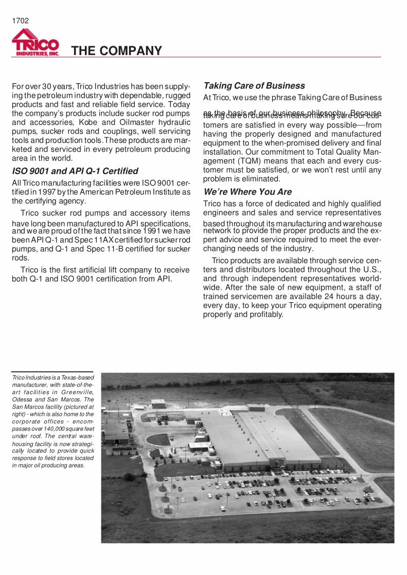
POLISHED ROD
WIRE LINE
POLISHED ROD CLAMP
WIRE LINE HANGER
POLISHED ROD LINERSTUFFING BOX
FLOW LINE
PUMPING TEE
TUBING HEAD
CASING HEAD
SURFACE CASING
PRODUCTION CASING
SUCKER ROD/POLISHED ROD COUPLING
SUCKER ROD/PONY ROD
TUBING
BARREL COUPLING
TUBING DRAIN
BARREL COUPLING
TUBING ANCHOR/CATCHER
BARREL COUPLING
"ON & OFF" ATTACHMENT
TOP CAGE
PLUNGER
BARREL TUBE
BALL & SEAT
BARREL COUPLING
STANDING VALVE PULLER
EXTENSION NIPPLE
TUBING COUPLING
TWO-CUP STANDING VALVE
SEATING NIPPLE
TUBING COUPLING
PERFORATED NIPPLE
TUBING COUPLING
BULL PLUG
BLEEDER
WELLHEADCONTROLVALVE
PRODUCTION CASING
PACKER & NOSE
BOTTOM HOLE ASSEMBLY
PISTON OR JET"FREE PUMP"
STANDING VALVE
PACKER
TRIPLEXPUMP
KOBE/OILMASTERHYDRAULIC PUMPING EQUIPMENT
SUCKER RODPUMPINGEQUIPMENT
SUBSURFACEHYDRAULIC PUMPS &AUXILIARY EQUIPMENT
SUBSURFACESUCKER ROD PUMPS,
PARTS & ACCESSORIES
SUCKER RODS& COUPLINGS
SUCKERROD
PUMP
UNIDRAULIC
KOBEOILMASTER ®
®
ROD PUMPS & ACCESSORIESSucker Rod Pumps .............1704Pump Barrels.......................1705Plungers ................. .............1706Presure ActuatedPlungers ................. .............1707Balls & Seats.......................1707Valve Cages ................. .......1708Holddowns...........................1709Bottom Discharge Valve.. ....1709Top Seals.............................1710Top Valves................. ..........1711
RODSSucker Rods........................1712Pony Rods.. .................. .......1713Rod Couplings.....................1713
HYDRAULIC PUMPSSystems Description .....1714 -- 1715Piston Pumps................1716 -- 1719Jet Pumps ................ .....1720 -- 1721Coiled Tubing Jet Pump ......1722Drill Stem Test ................. ....1723Unidraulic -- Single Vessel ..1724Unidraulic -- Dual Vessel .....1725Test Unit ..............................1725Triplex Pumps................1726 -- 1727Multiplex Pumps............1728 -- 1729Accessory Items............1730 -- 1731Computer Data/Well Info .....1732
PRODUCTION TOOLS“Y” Tool .................. ..............1733Mechanical TubingAnchor/Catcher ...................1734Tubing Anchor ............. ........1735Tubing Drains.. ..............1736 -- 1737On & Off Tool.......................1737Hydro-BalancedStuffing Box.. .................. .....1738Double-Pac Stuffing Boxes..1739Polished Rod Liners .... ........1739Polished Rods ................ .....1739Polished Rod Clamps..........1740
WELL SERVICE TOOLSSucker Rod Wrenches ........1741Paraffin Knife..... ..................1741Tap and Die Set...................1741Rod Hooks & Elevators .......1742Sucker Rod Sockets............1743
HYDRAULIC PUMPING EQUIPMENT
· PRESSURE CONTROL VALVES
·
WATER FLOOD CONTROL VALVES
· FLOW CONTROL VALVES
WELL SERVICE TOOLS
· ROD ELEVATORS
·
ROD SOCKETS
· ROD HOOKS
· ROD WRENCHES
PRODUCTION TOOLS
· HYDRAULIC TUBING ANCHORS
·
CROSSOVER ASSEMBLY -- “Y” TOOL
· PUMP TOP SEALS
OTHER TRICO PRODUCTS
All products described in red aremanufactured by Trico Industries, Inc.
CONTENTS
7/14/2019 Equipos Trico
http://slidepdf.com/reader/full/equipos-trico 4/44
SUCKER ROD PUMPS
1704
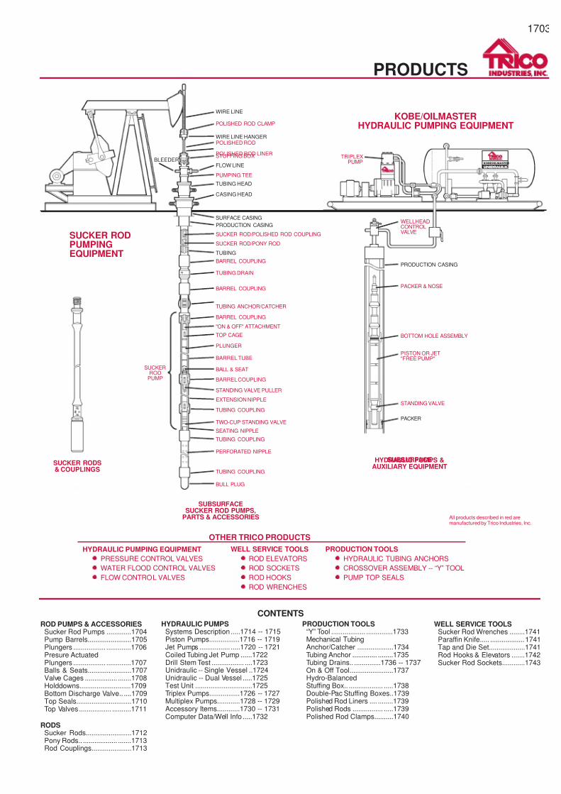
RWAM PUMP RHBC PUMPRWTC PUMP
THM PUMP
SUBSURFACE ROD PUMPS
Bottom Hold-Down Stationary BarrelInsert Pumps: RWB, RHB, RSBThis pump configuration is the most rugged and popular con-figuration for an insert pump.The location of thehold-down sealassembly gives this pump an advantage since the pressure onthe outside of the barrel tube balances damaging pressures in-side the barrel tube during pumping.Bottom hold-down pumpsin theheavy wall configuration canbe runtoextreme depths.
Top Hold-Down Insert Pumps: RWA, RHA,RSA
The advantage to this pump configuration is that the fluid dis-charge point is only inches away from the top of the hold-down,so there is normally not a problem with “sanding in” the pump inthe tubing, and never a problem with stagnant fluid collectingbetween the pump discharge point and the hold-down. Thispump also has more fluid submergence than any other pumpdesign.
Traveling Barrel Insert Pumps: RWT, RHT,RSTThis pump is used in particulate laden pumping conditions.Thebottom end of the moving barrel keeps particulates in suspen-sion in the fluid between the pump barrel and tubing inside di-ameter. And, when the pump is shut down, as when on a timeclock, the traveling valve closes and prevents sand and other
particulates from falling back into the pump.
Tubing Pumps: TH, TSThe tubing pump is a rugged, high volume pump which allowsthe operator to produce the maximum amount of fluid from anygiven size of tubing. For instance, themaximum plunger size foran insert pump installed inside2-3/8" tubing is 1-1/2". If a tubingpump is installed the plunger sizecan be increased to 1-3/4" re-sulting in a 36% increase in pump capacity.
Tubing pumps are available in sizes from 1-3/4" to 4-3/4" in APIand Slim-Hole configurations.
Subsurface Rod PumpsTrico subsurface rod pumps are available in every API size andtype and in all materials and finishes, standard and special. Asevery experiencedoperator knows,each oilwell has itsown dis-tinct personality and requires a particular type of pump assem-bly. Trico servicemen have the expertise—from years ofexperience—to know which configuration will do the best job.Their ability to match pump and well for peak production equalsthe enviable reputation of the rugged hardware they sell andservice. So no matter what you’re dealing with in the way of cor-rosion, abrasion, gas,etc., yourTrico representativewillnot onlytell you how to handle it, he’ll deliver the goods to get the jobdone fast. Trico service shops offer:
·
24-hour-a-day service, every day of the year.
·
Large local inventories.
·
Pumps for all standard tubing and casing sizes.
·
Barrels and plungers for all types of well conditions.
7/14/2019 Equipos Trico
http://slidepdf.com/reader/full/equipos-trico 5/44
SUCKER ROD PUMPS
1705
SUBSURFACE PUMP BARRELS
API -- RHAPI -- TH
API -- RSAPI -- RW
Subsurface Pump BarrelsAdvances in metallurgy and manufacturing give you...
Barrels with longer life in every well condition.
Trico subsurface pump barrels lead the field in thepetroleum in-dustry all over the world, for the best reason in the world—theydo a better job. Superior control of material quality is half thestory. The other half is superior control of straightness and fin-ish. So whatever problems your well presents, you can be surethat a Tricobarrelwill deliver thecapabilities it promises—givinglonger service itself, and promoting durability of other parts ofthe pump, too.
Full range of types available.
Whether your production is corrosive, abrasive, or both, there’sa Trico barrel to handle it. Trico makes them in fivebasic materi-als: regular steel, carburized steel, chrome I.D. steel,brass,andchrome I.D. brass—plus special materials. They are all preci-sion honed to a mirror finish, and Trico’s chrome plating tech-nique has set the industry standard. And Trico makes them inevery standard API configuration.
Tri-Carb BarrelsWhen severe abrasion and/or corrosion is experienced, Tri-Carb barrels are recommended for longer life. Tri-Carb is achemically-applied silicon carbide and nickel coating, which isextremely resistantto wear andcorrosion.It is a particularlycosteffective method whenhydrogensulfide (H2S) orcarbondioxide(CO2) is present.
Barrels coated with Tri-Carb provide these advantages:
·
Higher effective hardness.Tri-Carb surface yields a Rockwell hardness of C72-C75.
·
Lowers coefficient of friction.
·
Extends barrel life.
·
Continuous and uniform layer of protection on inside andoutside surfaces, including threads.
MATERIAL APPLICATIONS
MaterialService
Abrasion Corrosion
Low Moderate Severe None CO2 H2S
Regular Steel X X
Carburized Steel X X X X Mild Mild
Regular Steel(Chromed I.D.)
X X X Mild
Brass X X X
Brass(Chromed I.D.)
X X X X
Steel Tri-Carb X X X X
Brass Tri-Carb X X X X
7/14/2019 Equipos Trico
http://slidepdf.com/reader/full/equipos-trico 6/44
SUCKER ROD PUMPS
1706
PlungersTrico plungers are available in all standard API sizes andtypes—chrome, Mo-Hard and Mo-Hard with Monel pins. Thechrome units are the lowest cost plungers, with a hard and high
quality surface finish. The Mo-Hard, a thermo-sprayed unit, isTrico’s premium plunger.
Series 389 Mo-Hard PlungersPlungers last longer with unique Mo-Hard finish.
Trico Mo-Hard plungers are made of heavy wall seamless alloytubing, with a special high nickel hard-facing material sprayedon in a molten state. The result is a surface with a hardness ofRockwell Rc 58-62. That’s why they stand up to abrasion andcorrosion longer than ordinary plungers.
Lower lifting costsBesides itsextreme toughness, theMo-Hard surface also hasa
very low coefficient of friction against any kind of barrel.Barrelslast longer, and the pump runs smoother, easier and more effi-ciently. Pins can be nickel plated against corrosion.
Standard sizes
Standard sizes are available in 1-1/4, 1-1/2, 1-3/4, 1-25/32, 2-1/4, 2-3/4, 3-1/4, 3-3/4 AND 4-3/4 inches, ground to many stan-dard fits. Standard lengths are 3 through 6 feet.
Series 397 Mo-Hard Plungers withMonel PinsMonel pins and super-hard finish Mo-Hard plungers giveextra long life in the most corrosive wells.
The plunger area most vulnerable to corrosion is the pin.With-
out protection, corrosive elements will quickly chew through thethreaded wall and destroy pump efficiency.
To help overcome this problem, Trico offers the Series 397Plunger. Prior to final grind of the plunger, precision machinedMonel pins, with their inherent corrosion-resistant properties,are securely attached to each end of the plunger.
This combination results in a super-hard plunger with superiorabrasion and corrosion resistance throughout its full length, in- cluding the pin.
Standard sizes
Standard sizes are available in 1-1/4, 1-1/2, 1-3/4 and 2 inches,groundto anyfit desired.Standard lengths are3 through 6 feet.
MO-HARD PLUNGERS
SERIES 389
HARD-FACING
BONDEDBY
FUSING,WILL NOT
PEEL
RESISTSABRASION
ANDCORROSION
OPTIONAL
NICKEL-PLATEDPINSPREVENTCORROSION
HARD-FACEDWITH0.010”THICKNESSPER SIDE
MO-HARDENEDSURFACERc 58-62
LOWCOEFFICIENTOF FRICTION
HEAVYWALLSEAMLESSALLOYTUBING
SERIES 397
MONELPIN
MONELPIN
7/14/2019 Equipos Trico
http://slidepdf.com/reader/full/equipos-trico 7/44
SUCKER ROD PUMPS
1707
Pressure Actuated PlungersTrico pressure actuated plungers are precision machined fromseamless tubing, arehard surfacedwitha thermo-sprayedcoat-ing and ground to an exact fit. Wrench flats and API pins arestandard on each plunger.
These plungers incorporate nylon rings of split, one-piece con-struction. The nylon offers excellent strength and flexibility, re-sists corrosion and water, and performs well in sandy fluids.Each ring is cupped on top, and when used on stationary barrelpumps, hydrostatic pressure expands the ring on the upstrokeand relaxes on the downstroke.
Fourplunger configurationsare available—10-ring,20-ring, 40-ring and 60-ring. Generally, the 10-ring plunger is recom-mendedtodepthsof 1500 feet,the 20-ring plunger to 4500feet,the 40-ring plunger to6500 feet and the 60-ring plunger to9600feet.
Available sizes
The 20, 40 and 60-ring pressure actuated plungers are eachavailable in the following sizes: 1-1/4, 1-1/2, 1-5/8, 1-3/4, 2, 2-1/8, 2-1/4and2-3/4 inches.The 10-ring plunger is available in1-1/2" size only.
Balls and SeatsMore efficiency, longer service.
Trico balls and seats are machined to the highest standards in
the industry, so you get top performance out of your pump. AndTrico's materials meet or exceed all API requirements, so youget extra long service without problems.
Types for all conditions.Trico makesballs andseats ineight different materials tohandleevery degree of abrasion and corrosion.And theyare made inafull range of standard sizes.
PRESSURE ACTUATED PLUNGERS
BALL & SEAT
BALL AND SEAT COMBINATIONS & PART NUMBERS
Seat (Inches) Super Alloy Chromard Hi-Krome Rex-Alloy Carbide Carbide/NI Bonder Carbide Tit. Carbide
Ball (Inches) Stainless Chromard Hi-Krome Rex-Alloy Carbide Carbide/NI Binder Stainless Tit. Carbide
1-1/16 5/8 104-B29-110 104-B28-310 104-B26-110 104-B32-810
1-1/4 11/16 104-D29-1111-1/4 3/4 104-D29-112 104-D28-312 104-D26-212 104-D10-N12 104-D26-112 104-D32-812
1-1/2 7/8 104-F29-114 104-F31-514 104-F28-314 104-F10-N14
1-1/2 15/16 104-F29-115 104-F31-515 1 04-F28-315 1 04-F26-215 104-F10-N15 104-F26-115 1 04-F32-815
1-3/4 1 104-H15-116 104-H29-116 104-H31-516 104-H28-316 104-H10-N16 104-H260116
1-3/4 1-1/8 104-H15-118 104-H29-118 104-H31-518 104-H28-318 104-H26-218 104-H10-N18 104-H26-118 104-H32-818
2 1-1/8 104-K29-118 104-K28-318 104-K10-N18 104-K26-118
2 1-1/4 104-K29-120 104-K28-320 104-K26-220 104-K10-N20 104-K26-120
2-1/4 1-1/4 104-M15-120 104-M29-120 104-M28-320 104-M10-N20 104-M26-120 104-M32-820
2-1/4 1-3/8 104-M29-122 104-M28-322 104-M26-222 104-M10-N22 104-M26-122 104-M32-822
2-3/4 1-1/2 104-P15-124 104-P29-124 104-P28-324 104-P26-124
2-3/4 1-11/16 104-P15-127 104-P28-327 104-P26-127
3-1/4 2 104-R28-322 104-R26-132
3-3/4 2-1/4 104-T15-132 104-T28-332 104-T26-136
7/14/2019 Equipos Trico
http://slidepdf.com/reader/full/equipos-trico 8/44
SUCKER ROD PUMPS
1708
Valve CagesTough, basic materials, together with superior design, ensureslong service with Trico valve cages. Steel, brass and stainlesscages, both open and closed, are available.
Pump Insert Guided CagesThe most effective answer to minimize wear of criticalpump cage, ball and seat.
The Trico Pump Insert Guided Cage is designed to providelonger life for pump cages and balls and seats thanany conven-tionalcage combination.Its self-centering cage insert assures astraight drop for the ball. This reduces “float-flutter” ball actionandminimizesfriction wear in theball, seat andcage.Fluid pas-sage has minimum restrictions. A special high-temperature-resistant rubber gasket cushions the insert to soften impact.
The cage insert is cast of a special cobalt alloy which has excel-lent corrosionand shockresistance.All sizesaredesignedto re-
ceive API balls. The cage shell is machined in a choice ofmaterials—steel for normal or sandy wells and stainless steelfor corrosive wells.Available in 1-1/4, 1-1/2, 1-3/4, 2, 2-1/4 and2-3/4 inch sizes with a full range of top connections. Adaptablefor all combinations as shown above.
Hard Lined CagesWhen excessive wear on the valve ball is encountered, Trico’sHard LinedCagesarerecommended tohelp extendpump runs.
Hard lined cages have ball guides lined with Stellite6, anexcep-tionally tough material that reduces friction wear on the ball.Steel and stainless steel cages, in open, closed or insert de-signs, are available.
VALVE CAGES
PUMP INSERTGUIDED CAGE
BarrelConnectorHousing Plunger
ConnectorHousing
Insert
Ball
Seat
O-Ring
Seal Ring
4-WING INSERT GUIDED CAGE
PIN ENDPLUNGERBUSHING
GASKET
CAGEINSERT
SHELL
3-WING OPEN-TYPETOP CONNECTOR
3-WING OPEN-TYPEBOTTOM BUSHING
BARREL BOTTOMVALVE CONNECTOR
DOUBLE VALVECONNECTOR
PIN ENDPLUNGER BUSHING
ADAPTORS FOR VARIOUSINSERT CAGE COMBINATIONS
7/14/2019 Equipos Trico
http://slidepdf.com/reader/full/equipos-trico 9/44
SUCKER ROD PUMPS
1709
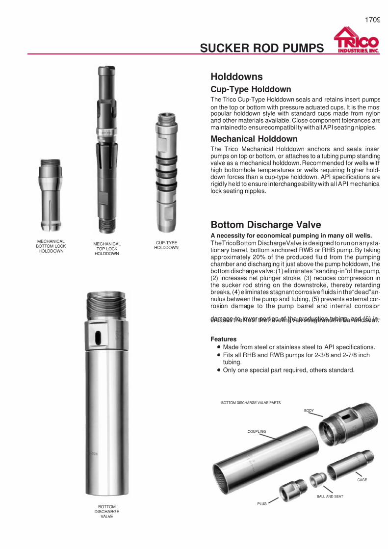
Holddowns
Cup-Type HolddownThe Trico Cup-Type Holddown seals and retains insert pumps
on the top or bottom with pressure actuated cups. It is the mostpopular holddown style with standard cups made from nylonand other materials available. Close component tolerances aremaintainedto ensurecompatibilitywithallAPI seating nipples.
Mechanical HolddownThe Trico Mechanical Holddown anchors and seals insertpumps on top or bottom, or attaches to a tubing pump standingvalve as a mechanical holddown.Recommended for wells withhigh bottomhole temperatures or wells requiring higher hold-down forces than a cup-type holddown. API specifications arerigidly held to ensure interchangeabilitywith all API mechanicalock seating nipples.
Bottom Discharge ValveA necessity for economical pumping in many oil wells.
TheTricoBottom DischargeValve isdesigned to runonanysta-tionary barrel, bottom anchored RWB or RHB pump. By takingapproximately 20% of the produced fluid from the pumpingchamber and discharging it just above the pump holddown, thebottom dischargevalve: (1) eliminates“sanding-in”of thepump,(2) increases net plunger stroke, (3) reduces compression inthe sucker rod string on the downstroke, thereby retardingbreaks, (4)eliminates stagnant corrosive fluids in the“dead”an-nulus between the pump and tubing, (5) prevents external cor-rosion damage to the pump barrel and internal corrosion
damage to lower portion of the production tubing, and (6) in-creases thelifeof thetravelingvalvecageandthe ball andseat.
Features
·
Made from steel or stainless steel to API specifications.
·
Fits all RHB and RWB pumps for 2-3/8 and 2-7/8 inchtubing.
·
Only one special part required, others standard.
BOTTOMDISCHARGE
VALVE
MECHANICALBOTTOM LOCK
HOLDDOWN
MECHANICALTOP LOCK
HOLDDOWN
CUP-TYPEHOLDDOWN
BOTTOM DISCHARGE VALVE PARTS
COUPLING
BODY
PLUG
BALL AND SEAT
CAGE
7/14/2019 Equipos Trico
http://slidepdf.com/reader/full/equipos-trico 10/44
SUCKER ROD PUMPS
1710
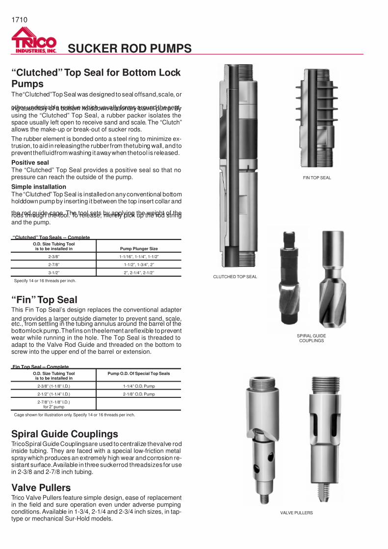
“Clutched” Top Seal for Bottom LockPumpsThe“Clutched”TopSeal was designed toseal offsand,scale, or
other undesirable residue which usually forms around the seat-ing assembly of a bottom holddown stationary barrel pump. Byusing the “Clutched” Top Seal, a rubber packer isolates thespace usually left open to receive sand and scale. The “Clutch”allows the make-up or break-out of sucker rods.
The rubber element is bonded onto a steel ring to minimize ex-trusion, toaid in releasingthe rubber from thetubing wall, and toprevent thefluidfromwashing itawaywhen thetool is released.
Positive sealThe “Clutched” Top Seal provides a positive seal so that nopressure can reach the outside of the pump.
Simple installation
The“Clutched” Top Seal is installedon anyconventional bottomholddown pump by inserting it between the top insert collar and
the rod guide cage. The tool sets by applying the weight of therods through the tool. To release, merely pick up the rod stringand the pump.
“Clutched” Top Seals -- Complete
O.D. Size Tubing Toolis to be installed in Pump Plunger Size
2-3/8” 1-1/16”, 1-1/4”, 1-1/2”
2-7/8” 1-1/2”, 1-3/4”, 2”
3-1/2” 2”, 2-1/4”, 2-1/2”
Specify 14 or 16 threads per inch.
“Fin” Top SealThis Fin Top Seal’s design replaces the conventional adapter
and provides a larger outside diameter to prevent sand, scale,etc., from settling in the tubing annulus around the barrel of thebottomlockpump.Thefinson theelement areflexible topreventwear while running in the hole. The Top Seal is threaded toadapt to the Valve Rod Guide and threaded on the bottom toscrew into the upper end of the barrel or extension.
Fin Top Seal -- Complete
O.D. Size Tubing Toolis to be installed in
Pump O.D. Of Special Top Seals
2-3/8” (1-1/8” I.D.) 1-1/4” O.D. Pump
2-1/2” (1-1/4” I.D.) 2-1/8” O.D. Pump
2-7/8” (1-1/8” I.D.)for 2” pump
Cage shown for illustration only. Specify 14 or 16 threads per inch.
Spiral Guide CouplingsTricoSpiral GuideCouplingsare used tocentralize thevalve rodinside tubing. They are faced with a special low-friction metalspraywhich produces an extremely high wear andcorrosion re-sistant surface.Available in three suckerrod threadsizes for usein 2-3/8 and 2-7/8 inch tubing.
Valve PullersTrico Valve Pullers feature simple design, ease of replacementin the field and sure operation even under adverse pumpingconditions.Available in 1-3/4, 2-1/4 and 2-3/4 inch sizes, in tap-type or mechanical Sur-Hold models.
CLUTCHED TOP SEAL
FIN TOP SEAL
SPIRAL GUIDECOUPLINGS
VALVE PULLERS
7/14/2019 Equipos Trico
http://slidepdf.com/reader/full/equipos-trico 11/44
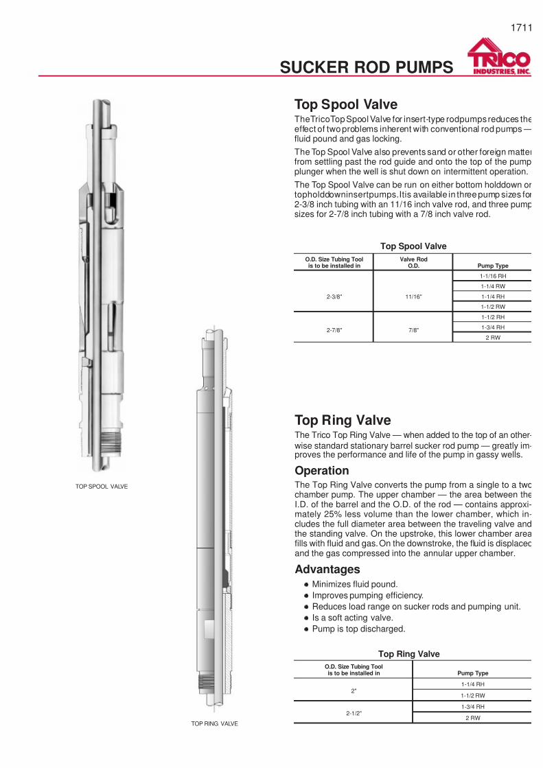
Top Spool ValveTheTricoTopSpoolValve for insert-type rodpumpsreduces theeffect of twoproblems inherent with conventional rod pumps —fluid pound and gas locking.
The Top Spool Valve also prevents sand or other foreign matterfrom settling past the rod guide and onto the top of the pumpplunger when the well is shut down on intermittent operation.
The Top Spool Valve can be run on either bottom holddown ortopholddowninsertpumps.Itis available in threepump sizes for2-3/8 inch tubing with an 11/16 inch valve rod, and three pumpsizes for 2-7/8 inch tubing with a 7/8 inch valve rod.
Top Ring ValveThe Trico Top Ring Valve — when added to the top of an other-
wise standard stationary barrel sucker rod pump — greatly im-proves the performance and life of the pump in gassy wells.
OperationThe Top Ring Valve converts the pump from a single to a twochamber pump. The upper chamber — the area between theI.D. of the barrel and the O.D. of the rod — contains approxi-mately 25% less volume than the lower chamber, which in-cludes the full diameter area between the traveling valve andthe standing valve. On the upstroke, this lower chamber areafills with fluid and gas.On the downstroke, the fluid is displacedand the gas compressed into the annular upper chamber.
Advantages·
Minimizes fluid pound.
·
Improves pumping efficiency.
·
Reduces load range on sucker rods and pumping unit.
·
Is a soft acting valve.
·
Pump is top discharged.
O.D. Size Tubing Toolis to be installed in Pump Type
2"1-1/4 RH
1-1/2 RW
2-1/2"1-3/4 RH
2 RW
Top Ring Valve
O.D. Size Tubing Toolis to be installed in
Valve RodO.D. Pump Type
2-3/8" 11/16"
1-1/16 RH
1-1/4 RW
1-1/4 RH
1-1/2 RW
2-7/8" 7/8"
1-1/2 RH
1-3/4 RH
2 RW
Top Spool Valve
TOP RING VALVE
TOP SPOOL VALVE
1711
SUCKER ROD PUMPS
7/14/2019 Equipos Trico
http://slidepdf.com/reader/full/equipos-trico 12/44
1712
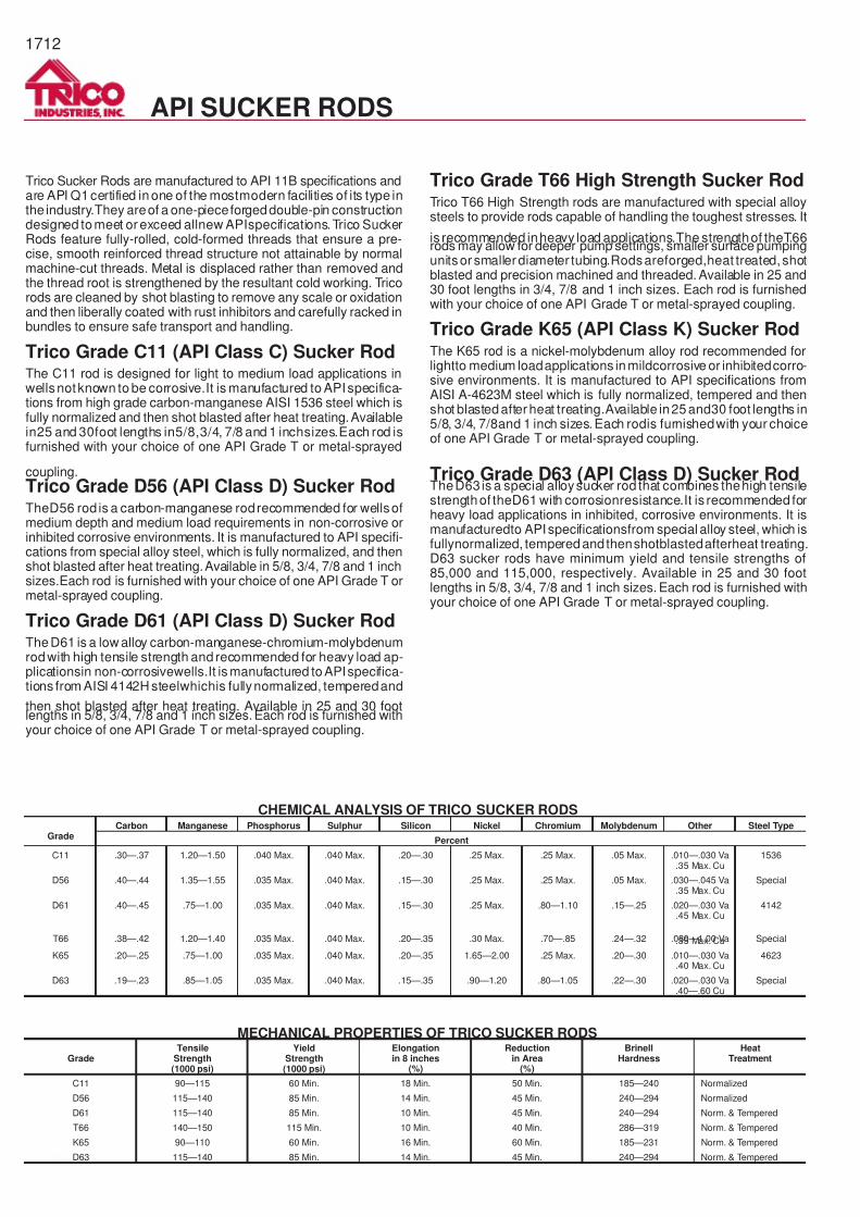
Trico Sucker Rods are manufactured to API 11B specifications andare API Q1certified inone of the mostmodern facilities of its type inthe industry.They areof a one-pieceforgeddouble-pin constructiondesigned tomeet or exceed allnew APIspecifications.Trico SuckerRods feature fully-rolled, cold-formed threads that ensure a pre-cise, smooth reinforced thread structure not attainable by normalmachine-cut threads. Metal is displaced rather than removed andthe thread root is strengthened by the resultant cold working. Tricorods are cleaned by shot blasting to remove any scale or oxidationand then liberally coated with rust inhibitors and carefully racked inbundles to ensure safe transport and handling.
Trico Grade C11 (API Class C) Sucker RodThe C11 rod is designed for light to medium load applications inwellsnotknown to be corrosive.It is manufactured to APIspecifica-tions from high grade carbon-manganese AISI 1536 steel which isfully normalized and then shot blasted after heat treating.Availablein25 and 30foot lengths in5/8,3/4, 7/8 and 1 inchsizes.Each rod isfurnished with your choice of one API Grade T or metal-sprayed
coupling.
Trico Grade D56 (API Class D) Sucker RodTheD56 rod is a carbon-manganese rodrecommended for wellsofmedium depth and medium load requirements in non-corrosive orinhibited corrosive environments. It is manufactured to API specifi-cations from special alloy steel, which is fully normalized, and thenshot blasted after heat treating.Available in 5/8, 3/4, 7/8 and 1 inchsizes.Each rod is furnished with your choice of one API Grade T ormetal-sprayed coupling.
Trico Grade D61 (API Class D) Sucker RodTheD61 is a low alloy carbon-manganese-chromium-molybdenumrodwith high tensile strength and recommended for heavy load ap-plicationsin non-corrosivewells.It is manufactured toAPIspecifica-tions from AISI 4142H steelwhichis fullynormalized, temperedand
then shot blasted after heat treating. Available in 25 and 30 footlengths in 5/8, 3/4, 7/8 and 1 inch sizes.Each rod is furnished withyour choice of one API Grade T or metal-sprayed coupling.
Trico Grade T66 High Strength Sucker RodTrico T66 High Strength rods are manufactured with special alloysteels to provide rods capable of handling the toughest stresses. It
is recommended inheavy load applications.The strengthof theT66rods may allow for deeper pump settings, smaller surface pumpingunitsor smaller diameter tubing.Rodsareforged,heat treated,shotblasted and precision machined and threaded. Available in 25 and30 foot lengths in 3/4, 7/8 and 1 inch sizes. Each rod is furnishedwith your choice of one API Grade T or metal-sprayed coupling.
Trico Grade K65 (API Class K) Sucker RodThe K65 rod is a nickel-molybdenum alloy rod recommended forlightto medium loadapplications inmildcorrosive or inhibitedcorro-sive environments. It is manufactured to API specifications fromAISI A-4623M steel which is fully normalized, tempered and thenshot blastedafter heat treating.Available in25and30 foot lengths in5/8, 3/4, 7/8and 1 inch sizes.Each rodis furnishedwith your choiceof one API Grade T or metal-sprayed coupling.
Trico Grade D63 (API Class D) Sucker RodTheD63 is a special alloysucker rod that combines thehigh tensilestrengthof theD61 with corrosionresistance.It is recommended forheavy load applications in inhibited, corrosive environments. It ismanufacturedto APIspecificationsfrom special alloy steel, which isfullynormalized, temperedandthenshotblastedafterheat treating.D63 sucker rods have minimum yield and tensile strengths of85,000 and 115,000, respectively. Available in 25 and 30 footlengths in 5/8, 3/4, 7/8 and 1 inch sizes. Each rod is furnished withyour choice of one API Grade T or metal-sprayed coupling.
GradeCarbon Manganese Phosphorus Sulphur Silicon Nickel Chromium Molybdenum Other Steel Type
Percent
C11 .30—.37 1.20—1.50 .040 Max. .040 Max. .20—.30 .25 Max. .25 Max. .05 Max. .010—.030 Va.35 Max. Cu
1536
D56 .40—.44 1.35—1.55 .035 Max. .040 Max. .15—.30 .25 Max. .25 Max. .05 Max. .030—.045 Va.35 Max. Cu
Special
D61 .40—.45 .75—1.00 .035 Max. .040 Max. .15—.30 .25 Max. .80—1.10 .15—.25 .020—.030 Va.45 Max. Cu
4142
T66 .38—.42 1.20—1.40 .035 Max. .040 Max. .20—.35 .30 Max. .70—.85 .24—.32 .080—1.00 Va.35 Max. Cu Special
K65 .20—.25 .75—1.00 .035 Max. .040 Max. .20—.35 1.65—2.00 .25 Max. .20—.30 .010—.030 Va.40 Max. Cu
4623
D63 .19—.23 .85—1.05 .035 Max. .040 Max. .15—.35 .90—1.20 .80—1.05 .22—.30 .020—.030 Va.40—.60 Cu
Special
GradeTensile
Strength(1000 psi)
YieldStrength(1000 psi)
Elongationin 8 inches
(%)
Reductionin Area
(%)
BrinellHardness
HeatTreatment
C11 90—115 60 Min. 18 Min. 50 Min. 185—240 Normalized
D56 115—140 85 Min. 14 Min. 45 Min. 240—294 Normalized
D61 115—140 85 Min. 10 Min. 45 Min. 240—294 Norm. & Tempered
T66 140—150 115 Min. 10 Min. 40 Min. 286—319 Norm. & Tempered
K65 90—110 60 Min. 16 Min. 60 Min. 185—231 Norm. & Tempered
D63 115—140 85 Min. 14 Min. 45 Min. 240—294 Norm. & Tempered
MECHANICAL PROPERTIES OF TRICO SUCKER RODS
CHEMICAL ANALYSIS OF TRICO SUCKER RODS
API SUCKER RODS
7/14/2019 Equipos Trico
http://slidepdf.com/reader/full/equipos-trico 13/44
1713
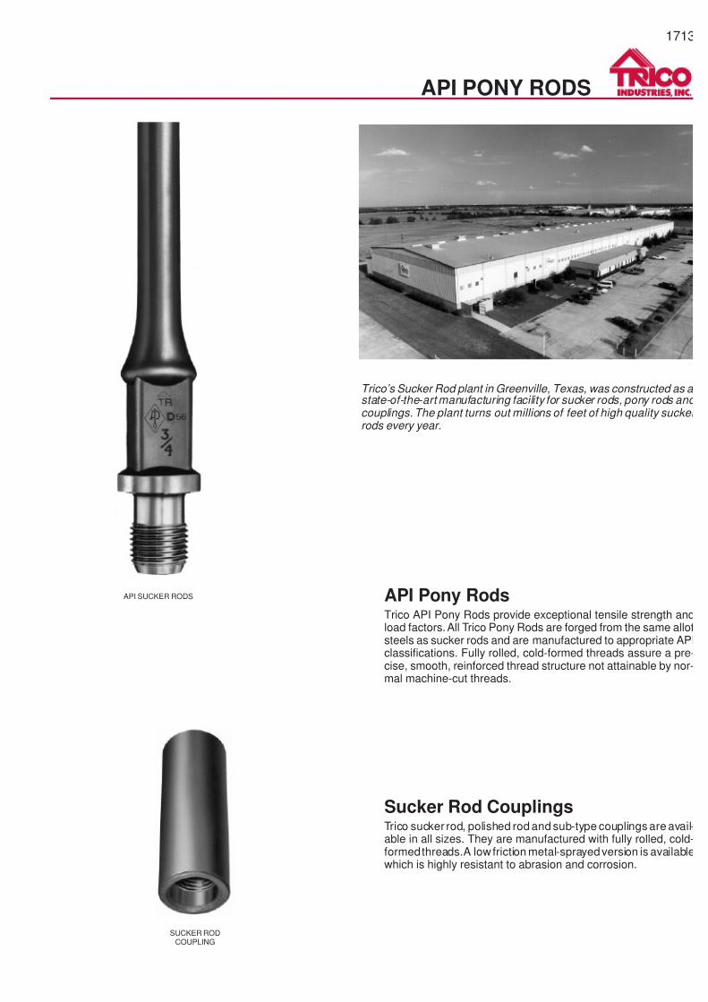
API Pony RodsTrico API Pony Rods provide exceptional tensile strength andload factors.All Trico Pony Rods are forged from the same allotsteels as sucker rods and are manufactured to appropriate APIclassifications. Fully rolled, cold-formed threads assure a pre-cise, smooth, reinforced thread structure not attainable by nor-mal machine-cut threads.
Sucker Rod CouplingsTrico sucker rod, polished rod and sub-type couplings are avail-able in all sizes. They are manufactured with fully rolled, cold-formedthreads.A low friction metal-sprayedversion is availablewhich is highly resistant to abrasion and corrosion.
API SUCKER RODS
API PONY RODS
SUCKER RODCOUPLING
Trico’s Sucker Rod plant in Greenville, Texas, was constructed as a state-of-the-art manufacturing facility for sucker rods, pony rods andcouplings. The plant turns out millions of feet of high quality suckerrods every year.
7/14/2019 Equipos Trico
http://slidepdf.com/reader/full/equipos-trico 14/44
1714
HYDRAULIC PUMPS
POWER FLUIDSTORAGE
PRIMEMOVER
TRIPLEX
CONTROL STATION
WELLHEAD
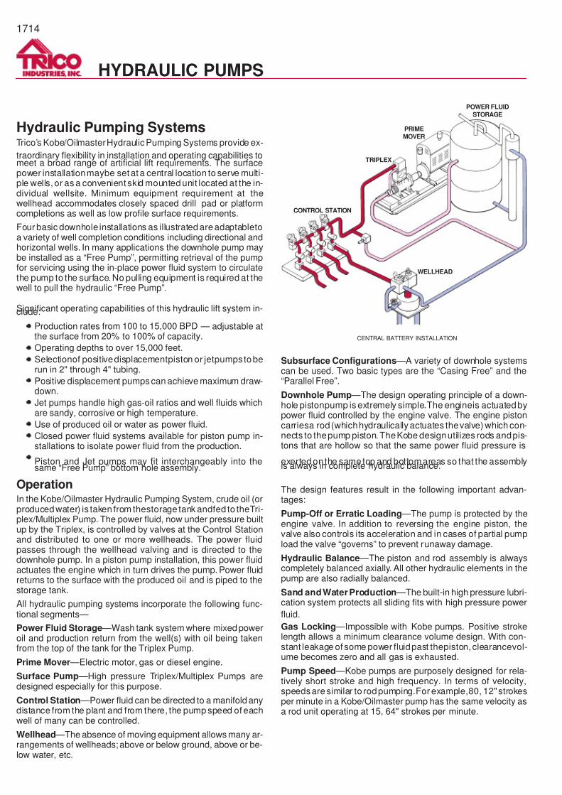
CENTRAL BATTERY INSTALLATION
Hydraulic Pumping SystemsTrico’s Kobe/OilmasterHydraulic Pumping Systems provide ex-
traordinary flexibility in installation and operating capabilities tomeet a broad range of artificial lift requirements. The surfacepower installationmaybe setat a central location to serve multi-ple wells, or as a convenient skid mounted unit located at the in-dividual wellsite. Minimum equipment requirement at thewellhead accommodates closely spaced drill pad or platformcompletions as well as low profile surface requirements.
Four basic downhole installations as illustrated areadaptabletoa variety of well completion conditions including directional andhorizontal wells. In many applications the downhole pump maybe installed as a “Free Pump”, permitting retrieval of the pumpfor servicing using the in-place power fluid system to circulatethe pump to the surface. No pulling equipment is required at thewell to pull the hydraulic “Free Pump”.
Significant operating capabilities of this hydraulic lift system in-clude:
·
Production rates from 100 to 15,000 BPD — adjustable atthe surface from 20% to 100% of capacity.
·
Operating depths to over 15,000 feet.
·
Selectionof positivedisplacementpiston or jetpumpstoberun in 2" through 4" tubing.
·
Positive displacement pumps can achieve maximum draw-down.
·
Jet pumps handle high gas-oil ratios and well fluids whichare sandy, corrosive or high temperature.
·
Use of produced oil or water as power fluid.
·
Closed power fluid systems available for piston pump in-stallations to isolate power fluid from the production.
· Piston and Jet pumps may fit interchangeably into thesame “Free Pump” bottom hole assembly.
OperationIn the Kobe/Oilmaster Hydraulic Pumping System, crude oil (orproducedwater) is taken from thestorage tank andfed to theTri-plex/Multiplex Pump. The power fluid, now under pressure builtup by the Triplex, is controlled by valves at the Control Stationand distributed to one or more wellheads. The power fluidpasses through the wellhead valving and is directed to thedownhole pump. In a piston pump installation, this power fluidactuates the engine which in turn drives the pump. Power fluidreturns to the surface with the produced oil and is piped to thestorage tank.
All hydraulic pumping systems incorporate the following func-tional segments—
Power Fluid Storage —Wash tank system where mixed poweroil and production return from the well(s) with oil being takenfrom the top of the tank for the Triplex Pump.
Prime Mover —Electric motor, gas or diesel engine.
Surface Pump —High pressure Triplex/Multiplex Pumps aredesigned especially for this purpose.
Control Station —Power fluid can be directed to a manifold anydistance from the plant and from there, the pump speed of eachwell of many can be controlled.
Wellhead —The absence of moving equipment allows many ar-rangements of wellheads; above or below ground, above or be-low water, etc.
Subsurface Configurations —A variety of downhole systemscan be used. Two basic types are the “Casing Free” and the“Parallel Free”.
Downhole Pump —The design operating principle of a down-hole pistonpump is extremely simple.The engineis actuatedbypower fluid controlled by the engine valve. The engine pistoncarriesa rod(whichhydraulically actuates thevalve) which con-nects to thepump piston.TheKobe designutilizes rods andpis-tons that are hollow so that the same power fluid pressure is
exerted on the same top and bottom areas so that the assemblyis always in complete hydraulic balance.
The design features result in the following important advan-tages:
Pump-Off or Erratic Loading —The pump is protected by theengine valve. In addition to reversing the engine piston, thevalve also controls its acceleration and in cases of partial pumpload the valve “governs” to prevent runaway damage.
Hydraulic Balance —The piston and rod assembly is alwayscompletely balanced axially. All other hydraulic elements in thepump are also radially balanced.
Sand andWaterProduction —The built-in high pressure lubri-cation system protects all sliding fits with high pressure power
fluid.
Gas Locking —Impossible with Kobe pumps. Positive strokelength allows a minimum clearance volume design. With con-stant leakage of some power fluidpast thepiston, clearancevol-ume becomes zero and all gas is exhausted.
Pump Speed —Kobe pumps are purposely designed for rela-tively short stroke and high frequency. In terms of velocity,speedsaresimilar to rodpumping.For example,80, 12"strokesper minute in a Kobe/Oilmaster pump has the same velocity asa rod unit operating at 15, 64" strokes per minute.
7/14/2019 Equipos Trico
http://slidepdf.com/reader/full/equipos-trico 15/44
1715
HYDRAULIC PUMPS
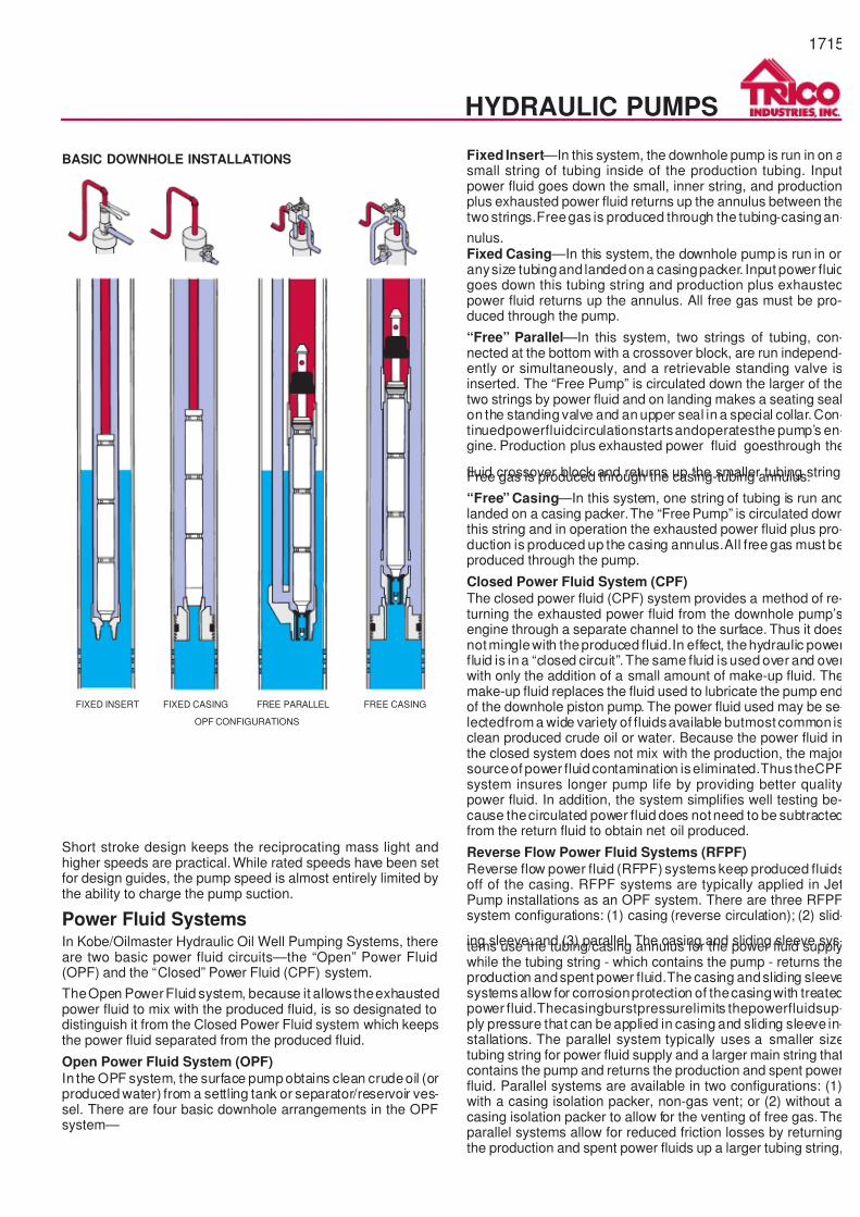
FIXED INSERT FIXED CASING FREE PARALLEL FREE CASING
OPF CONFIGURATIONS
BASIC DOWNHOLE INSTALLATIONS
Short stroke design keeps the reciprocating mass light andhigher speeds are practical. While rated speeds have been setfor design guides, the pump speed is almost entirely limited bythe ability to charge the pump suction.
Power Fluid SystemsIn Kobe/Oilmaster Hydraulic Oil Well Pumping Systems, thereare two basic power fluid circuits—the “Open” Power Fluid(OPF) and the “Closed” Power Fluid (CPF) system.
TheOpen PowerFluid system, because it allowstheexhaustedpower fluid to mix with the produced fluid, is so designated todistinguish it from the Closed Power Fluid system which keepsthe power fluid separated from the produced fluid.
Open Power Fluid System (OPF)
In the OPF system, the surface pump obtains clean crudeoil (orproduced water) from a settling tank or separator/reservoir ves-sel. There are four basic downhole arrangements in the OPFsystem—
Fixed Insert —In this system, the downhole pump is run in on asmall string of tubing inside of the production tubing. Inputpower fluid goes down the small, inner string, and productionplus exhausted power fluid returns up the annulus between thetwostrings.Freegas is produced through the tubing-casingan-
nulus.Fixed Casing —In this system, the downhole pump is run in onanysize tubingand landedon a casingpacker. Input power fluidgoes down this tubing string and production plus exhaustedpower fluid returns up the annulus. All free gas must be pro-duced through the pump.
“Free” Parallel —In this system, two strings of tubing, con-nected at the bottom with a crossover block, are run independ-ently or simultaneously, and a retrievable standing valve isinserted. The “Free Pump” is circulated down the larger of thetwo strings by power fluid and on landing makes a seating sealon the standing valve and an upper seal in a special collar. Con-tinuedpowerfluidcirculationstartsandoperatesthe pump’s en-gine. Production plus exhausted power fluid goesthrough the
fluid crossover block and returns up the smaller tubing string.Free gas is produced through the casing-tubing annulus.
“Free” Casing —In this system, one string of tubing is run andlanded on a casing packer.The “Free Pump” is circulated downthis string and in operation the exhausted power fluid plus pro-duction is produced up the casing annulus.All free gas must beproduced through the pump.
Closed Power Fluid System (CPF)
The closed power fluid (CPF) system provides a method of re-turning the exhausted power fluid from the downhole pump’sengine through a separate channel to the surface. Thus it doesnot minglewith theproduced fluid.In effect, thehydraulic powerfluid is in a “closed circuit”. The same fluid is used over and overwith only the addition of a small amount of make-up fluid. Themake-up fluid replaces the fluid used to lubricate the pump endof the downhole piston pump. The power fluid used may be se-lectedfrom a wide variety of fluidsavailable butmost common isclean produced crude oil or water. Because the power fluid inthe closed system does not mix with the production, the majorsourceof power fluid contamination iseliminated.ThustheCPFsystem insures longer pump life by providing better qualitypower fluid. In addition, the system simplifies well testing be-cause thecirculated power fluid does notneed to be subtractedfrom the return fluid to obtain net oil produced.
Reverse Flow Power Fluid Systems (RFPF)
Reverse flow power fluid (RFPF) systems keep produced fluidsoff of the casing. RFPF systems are typically applied in JetPump installations as an OPF system. There are three RFPFsystem configurations: (1) casing (reverse circulation); (2) slid-
ing sleeve; and (3) parallel. The casing and sliding sleeve sys-tems use the tubing/casing annulus for the power fluid supplywhile the tubing string - which contains the pump - returns theproduction andspent power fluid.The casing andsliding sleevesystemsallow for corrosionprotection of thecasingwith treatedpower fluid.Thecasingburstpressurelimits thepowerfluidsup-ply pressure that can be applied in casing and sliding sleeve in-stallations. The parallel system typically uses a smaller sizetubing string for power fluid supply and a larger main string thatcontains the pump and returns the production and spent powerfluid. Parallel systems are available in two configurations: (1)with a casing isolation packer, non-gas vent; or (2) without acasing isolation packer to allow for the venting of free gas. Theparallel systems allow for reduced friction losses by returningthe production and spent power fluids up a larger tubing string,
7/14/2019 Equipos Trico
http://slidepdf.com/reader/full/equipos-trico 16/44
Hydraulic Piston Pumps
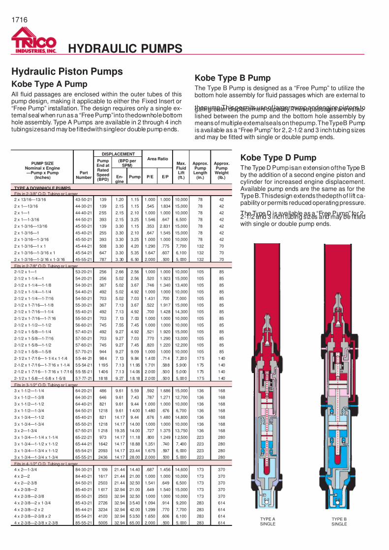
Kobe Type A PumpAll fluid passages are enclosed within the outer tubes of thispump design, making it applicable to either the Fixed Insert or“Free Pump” installation. The design requires only a single ex-ternalseal when runas a “FreePump”into thedownholebottomhole assembly. Type A Pumps are available in 2 through 4 inchtubingsizesand may be fittedwithsingleor double pump ends.
Kobe Type B PumpThe Type B Pump is designed as a “Free Pump” to utilize thebottom hole assembly for fluid passages which are external to
thepump.This permits useof largerpump andengine pistons togaingreater displacement capacity.Thesepassages are estab-lished between the pump and the bottom hole assembly bymeansof multipleexternalsealson thepump.TheTypeB Pumpis available as a “Free Pump” for 2, 2-1/2 and 3 inch tubing sizesand may be fitted with single or double pump ends.
Kobe Type D PumpThe Type D Pump isan extension ofthe Type Bby the addition of a second engine piston andcylinder for increased engine displacement.Available pump ends are the same as for theTypeB.Thisdesign extends thedepthof lift ca-pabilityor permits reduced operatingpressure.
The Type D is available as a “Free Pump” for 2,2-1/2 and 3 inch tubing sizes and may be fittedwith single or double pump ends.
PUMP SIZENominal x Engine —Pump x Pump
(Inches)Part
Number
DISPLACEMENTArea Ratio
Max.FluidLift(ft.)
Approx.PumpLength
(in.)
Approx.PumpWeight
(lb.)
PumpEnd atRatedSpeed(BPD)
(BPD perSPM)
En-gine
Pump P/E E/P
TYPE A DOWNHOLE PUMPS
Fits in 2-3/8" O.D. Tubing or Larger
2 x 13/16—13/16 43-50-21 139 1.20 1.15 1.000 1.000 10,000 78 42
2 x 1—13/16 44-30-21 139 2.15 1.15 .545 1.834 15,000 78 42
2 x 1—1 44-40-21 255 2.15 2.10 1.000 1.000 10,000 78 42
2 x 1—1-3/16 44-50-21 393 2.15 3.25 1.546 .647 6,500 78 42
2 x 1-3/16—13/16 45-50-21 139 3.30 1.15 .353 2.831 15,000 78 42
2 x 1-3/16—1 45-40-21 255 3.30 2.10 .647 1.545 15,000 78 42
2 x 1-3/16—1-3/16 45-50-21 393 3.30 3.25 1 .000 1.000 10,000 78 42
2 x 1-3/16—1 x 1 45-44-21 508 3.30 4.20 1.290 .775 7,700 132 70
2 x 1-3/16—1-3/16 x 1 45-54-21 647 3.30 5.35 1.647 .607 6,100 132 70
2 x 1-3/16—1-3/16 x 1-3/16 45-55-21 787 3.30 6.50 2.000 .500 5,000 132 70
Fits in 2-7/8" O.D. Tubing or Larger
2-1/2 x 1—1 53-20-21 256 2.66 2.56 1.000 1.000 10,000 105 85
2-1/2 x 1-1/4—1 54-20-21 256 5.02 2.56 .520 1.923 15,000 105 85
2-1/2 x 1-1/4—1-1/8 54-30-21 367 5.02 3.67 .746 1 .340 13,400 105 85
2-1/2 x 1-1/4—1-1/4 54-40-21 492 5.02 4.92 1.000 1.000 10,000 105 85
2-1/2 x 1-1/4—1-7/16 54-50-21 703 5.02 7.03 1 .431 . 700 7,000 105 85
2-1/2 x 1-7/16—1-1/8 55-30-21 367 7.13 3.67 .522 1.917 15,000 105 85
2-1/2 x 1-7/16—1-1/4 55-40-21 492 7.13 4.92 .700 1.428 14,300 105 85
2-1/2 x 1-7/16—1-7/16 55-50-21 703 7.13 7.03 1.000 1.000 10,000 105 85
2-1/2 x 1-1/2—1-1/2 56-60-21 745 7.55 7.45 1.000 1.000 10,000 105 85
2-1/2 x 1-5/8—1-1/4 57-40-21 492 9.27 4.92 .521 1 .920 15,000 105 85
2-1/2 x 1-5/8—1-7/16 57-50-21 703 9.27 7.03 .770 1.290 13,000 105 85
2-1/2 x 1-5/8—1-1/2 57-60-21 745 9.27 7.45 .820 1 .220 12,200 105 85
2-1/2 x 1-5/8—1-5/8 57-70-21 944 9.27 9.09 1.000 1.000 10,000 105 85
2-1/2 x 1-7 /16—1-1/4 x 1-1 /4 55-44-21 984 7.13 9.84 1 .400 .714 7,200 175 140
2-1/2 x 1-7/16—1-7/16 x 1-1/4 55-54-21 1195 7.13 11.95 1.701 .588 5,900 175 140
2-1/2 x 1-7/16—1-7/16 x 1-7/16 55-55-21 1406 7.13 14.06 2.000 .500 5,000 175 140
2-1/2 x 1-5 /8—1-5/8 x 1-5/8 57-77-21 1818 9.27 18.18 2 .000 .500 5,000 175 140
Fits in 3-1/2" O.D. Tubing or Larger
3 x 1-1/2—1-1/4 64-20-21 486 9.61 5.59 .592 1.686 15,000 136 168
3 x 1-1/2—1-3/8 64-30-21 646 9.61 7.43 .787 1.271 12,700 136 168
3 x 1-1/2—1-1/2 64-40-21 821 9.61 9.44 1 .000 1.000 10,000 136 168
3 x 1-1/2—1-3/4 64-50-21 1218 9.61 1 4.00 1.480 . 676 6,700 136 168
3 x 1-3/4—1-1/2 65-40-21 821 14.17 9.44 .676 1 .480 14,800 136 168
3 x 1-3/4—1-3/4 65-50-21 1218 14.17 14.00 1.000 1.000 10,000 136 168
3 x 2—1-3/4 67-50-21 1 218 19.35 14.00 .727 1.375 13,750 136 168
3 x 1-3/4—1-1/4 x 1-1/4 65-22-21 973 14.17 11.18 .800 1.249 12,500 223 280
3 x 1-3/4—1-1/2 x 1-1/2 65-44-21 1642 14.17 18.88 1.351 .740 7,400 223 280
3 x 1-3/4—1-3/4 x 1-1/2 65-54-21 2093 14.17 23.44 1.675 .597 6,000 223 280
3 x 1-3/4—1-3/4 x 1-3/4 65-55-21 2436 14.17 28.00 2.000 .500 5,000 223 280
Fits in 4-1/2" O.D. Tubing or Larger
4 x 2—1-3/4 84-30-21 1 109 21.44 14.40 .687 1.456 14,600 173 370
4 x 2—2 84-40-21 1617 21.44 21.00 1.000 1.000 10,000 173 370
4 x 2—2-3/8 84-50-21 2503 21.44 32.50 1.541 .649 6,500 173 370
4 x 2-3/8—2 85-40-21 1 617 32.94 21.00 .649 1.540 15,000 173 370
4 x 2-3/8—2-3/8 85-50-21 2503 32.94 32.50 1.000 1.000 10,000 173 370
4 x 2-3/8—2 x 1-3/4 85-43-21 2726 32.94 3 5.40 1 .094 .914 9,200 283 614
4 x 2-3/8—2 x 2 85-44-21 3234 32.94 42.00 1.299 .770 7,700 283 614
4 x 2-3/8—2-3/8 x 2 85-54-21 4120 32.94 5 3.50 1 .650 .606 6,100 283 614
4 x 2-3/8—2-3/8 x 2-3/8 85-55-21 5005 32.94 65.00 2.000 .500 5,000 283 614
1716
HYDRAULIC PUMPS
TYPE ASINGLE
TYPE BSINGLE
7/14/2019 Equipos Trico
http://slidepdf.com/reader/full/equipos-trico 17/44
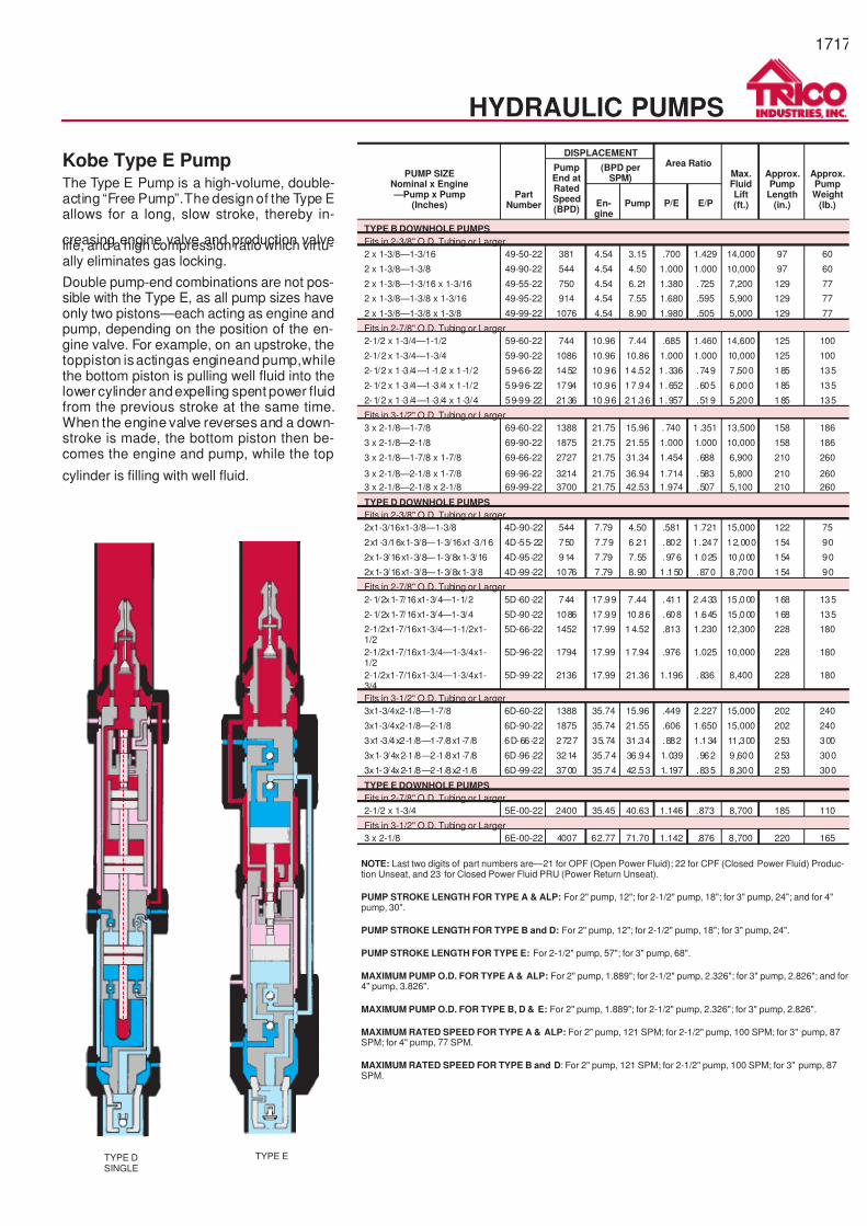
Kobe Type E PumpThe Type E Pump is a high-volume, double-acting “Free Pump”.The design of the Type Eallows for a long, slow stroke, thereby in-
creasing engine valve and production valvelife, and a high compression ratio which virtu-ally eliminates gas locking.
Double pump-end combinations are not pos-sible with the Type E, as all pump sizes haveonly two pistons—each acting as engine andpump, depending on the position of the en-gine valve. For example, on an upstroke, thetoppiston isactingas engineand pump,whilethe bottom piston is pulling well fluid into thelower cylinder andexpelling spent power fluidfrom the previous stroke at the same time.When the engine valve reverses and a down-stroke is made, the bottom piston then be-comes the engine and pump, while the top
cylinder is filling with well fluid.
PUMP SIZENominal x Engine —Pump x Pump
(Inches)Part
Number
DISPLACEMENTArea Ratio
Max.FluidLift(ft.)
Approx.Pump
Length(in.)
Approx.PumpWeight
(lb.)
PumpEnd atRatedSpeed(BPD)
(BPD perSPM)
En-gine
Pump P/E E/P
TYPE B DOWNHOLE PUMPS
Fits in 2-3/8" O.D. Tubing or Larger
2 x 1-3/8—1-3/16 49-50-22 381 4.54 3.15 .700 1.429 14,000 97 60
2 x 1-3/8—1-3/8 49-90-22 544 4.54 4.50 1.000 1.000 10,000 97 60
2 x 1-3/8—1-3/16 x 1-3/16 49-55-22 750 4.54 6.21 1.380 .725 7,200 129 77
2 x 1-3/8—1-3/8 x 1-3/16 49-95-22 914 4.54 7.55 1.680 .595 5,900 129 77
2 x 1-3/8—1-3/8 x 1-3/8 49-99-22 1076 4.54 8.90 1.980 .505 5,000 129 77
Fits in 2-7/8" O.D. Tubing or Larger
2-1/2 x 1-3/4—1-1/2 59-60-22 744 10.96 7.44 .685 1.460 14,600 125 100
2-1/2 x 1-3/4—1-3/4 59-90-22 1086 10.96 10.86 1.000 1.000 10,000 125 100
2-1/2 x 1-3 /4—1-1/2 x 1-1/2 59-66-22 1452 10.96 14.52 1 .336 .749 7 ,500 185 135
2-1/2 x 1-3 /4—1-3/4 x 1-1/2 59-96-22 1794 10.96 17.94 1 .652 .605 6 ,000 185 135
2-1/2 x 1-3 /4—1-3/4 x 1-3/4 59-99-22 2136 10.96 21.36 1 .957 .519 5 ,200 185 135
Fits in 3-1/2" O.D. Tubing or Larger
3 x 2-1/8—1-7/8 69-60-22 1388 21.75 15.96 . 740 1 .351 13,500 158 186
3 x 2-1/8—2-1/8 69-90-22 1875 21.75 21.55 1.000 1.000 10,000 158 186
3 x 2-1/8—1-7/8 x 1-7/8 69-66-22 2727 21.75 31.34 1.454 .688 6,900 210 260
3 x 2-1/8—2-1/8 x 1-7/8 69-96-22 3214 21.75 36.94 1.714 .583 5,800 210 260
3 x 2-1/8—2-1/8 x 2-1/8 69-99-22 3700 21.75 42.53 1.974 .507 5,100 210 260
TYPE D DOWNHOLE PUMPS
Fits in 2-3/8" O.D. Tubing or Larger
2x1-3/16x1-3/8—1-3/8 4D-90-22 544 7.79 4.50 .581 1 .721 15,000 122 75
2x1-3/16x1-3/8—1-3/16x1-3/16 4D-55-22 750 7.79 6.21 .802 1.247 12,000 154 90
2x1-3/16x1-3/8—1-3/8x1-3/16 4D-95-22 914 7 .79 7.55 .976 1 .025 10,000 154 90
2x1-3/16x1-3/8—1-3/8x1-3/8 4D-99-22 1076 7 .79 8.90 1 .150 .870 8 ,700 154 90
Fits in 2-7/8" O.D. Tubing or Larger
2-1/2x1-7/16x1-3/4—1-1/2 5D-60-22 744 17.99 7 .44 .411 2 .433 15,000 168 135
2-1/2x1-7/16x1-3/4—1-3/4 5D-90-22 1086 17.99 10.86 .608 1 .645 15,000 168 135
2-1/2x1-7/16x1-3/4—1-1/2x1-1/2
5D-66-22 1452 17.99 14.52 .813 1.230 12,300 228 180
2-1/2x1-7/16x1-3/4—1-3/4x1-1/2
5D-96-22 1794 17.99 17.94 .976 1.025 10,000 228 180
2-1/2x1-7/16x1-3/4—1-3/4x1-3/4
5D-99-22 2136 17.99 21.36 1.196 .836 8,400 228 180
Fits in 3-1/2" O.D. Tubing or Larger
3x1-3/4x2-1/8—1-7/8 6D-60-22 1388 35.74 15.96 .449 2.227 15,000 202 240
3x1-3/4x2-1/8—2-1/8 6D-90-22 1875 35.74 21.55 .606 1.650 15,000 202 240
3x1-3/4x2-1/8—1-7/8x1-7/8 6D-66-22 2727 35.74 31.34 .882 1.134 11,300 253 300
3x1-3/4x2-1/8—2-1/8x1-7/8 6D-96-22 3214 35.74 36.94 1.039 .962 9 ,600 253 300
3x1-3/4x2-1/8—2-1/8x2-1/8 6D-99-22 3700 35.74 42.53 1.197 .835 8 ,300 253 300
TYPE E DOWNHOLE PUMPS
Fits in 2-7/8" O.D. Tubing or Larger
2-1/2 x 1-3/4 5E-00-22 2400 35.45 40.63 1.146 .873 8,700 185 110
Fits in 3-1/2" O.D. Tubing or Larger
3 x 2-1/8 6E-00-22 4007 62.77 71.70 1.142 .876 8,700 220 165
NOTE: Last two digits of part numbers are—21 for OPF (Open Power Fluid); 22 for CPF (Closed Power Fluid) Produc-tion Unseat, and 23 for Closed Power Fluid PRU (Power Return Unseat).
PUMP STROKE LENGTH FOR TYPE A & ALP: For 2" pump, 12"; for 2-1/2" pump, 18"; for 3" pump, 24"; and for 4"pump, 30".
PUMP STROKE LENGTH FOR TYPE B and D: For 2" pump, 12"; for 2-1/2" pump, 18"; for 3" pump, 24".
PUMP STROKE LENGTH FOR TYPE E: For 2-1/2" pump, 57"; for 3" pump, 68".
MAXIMUM PUMP O.D. FOR TYPE A & ALP: For 2" pump, 1.889"; for 2-1/2" pump, 2.326"; for 3" pump, 2.826"; and for4" pump, 3.826".
MAXIMUM PUMP O.D. FOR TYPE B, D & E: For 2" pump, 1.889"; for 2-1/2" pump, 2.326"; for 3" pump, 2.826".
MAXIMUM RATED SPEED FOR TYPE A & ALP: For 2" pump, 121 SPM; for 2-1/2" pump, 100 SPM; for 3" pump, 87SPM; for 4" pump, 77 SPM.
MAXIMUM RATED SPEED FOR TYPE B and D: For 2" pump, 121 SPM; for 2-1/2" pump, 100 SPM; for 3" pump, 87SPM.
1717
HYDRAULIC PUMPS
TYPE DSINGLE
TYPE E
7/14/2019 Equipos Trico
http://slidepdf.com/reader/full/equipos-trico 18/44
1718
PUMP SIZENominal—Pump x Pump
(Inches)Part
Number
DISPLACEMENTArea Ratio
PumpEnd atRatedSpeed(BPD)
(BPD per SPM)
Engine Pump P/E E/P
TYPE ALP DOWNHOLE PUMPS
Fits in 2-7/8" O.D. Tubing or Larger
2-1/2—1 5A2-20-21 256 14.40 2.56 .178 5.615
2-1/2—1-1/8 5A2-30-21 367 14.46 3.67 .256 3.911
2-1/2—1-1/4 5A2-40-21 492 14.46 4.92 .342 2.920
2-1/2—1-7/16 5A2-50-21 703 14.46 7.03 .489 2.004
2-1/2—1-1/2 5A2-60-21 745 14.46 7.45 .543 1.840
2-1/2—1-5/8 5A2-70-21 944 14.46 9.44 .657 1.521
2-1/2—1-1/4 x 1-1/4 5A2-44-21 984 14.46 9.84 .685 1.460
2-1/2—1-7/16 x 1-1/4 5A2-54-21 1195 14.46 11.95 .832 1.202
2-1/2—1-7/16 x 1-7/16 5A2-55-21 1406 14.46 14.06 .979 1.022
2-1/2—1-5/8 x 1-5/8 5A2-77-21 1888 14.46 18.88 1.315 .760
Fits in 3-1/2" O.D. Tubing or Larger
3—1-1/4 6A2-20-21 486 26.79 5.59 .210 4.766
3—1-3/8 6A2-30-21 646 26.79 7.43 .279 3.580
3—1-1/2 6A2-40-21 821 26.79 9.44 .354 2.824
3—1-3/4 6A2-50-21 1218 26.79 14.00 .525 4.906
3—1-1/4 x 1-1/4 6A2-22-21 973 26.79 11.18 .420 2.383
3—1-1/2 x 1-1/2 6A2-44-21 1643 26.79 18.88 .708 1.412
3—1-3/4 x 1-1/2 6A2-54-21 2039 26.79 23.44 .879 1.130
3—1-3/4 x 1-3/4 6A2-55-21 2436 26.79 28.40 1.049 .953
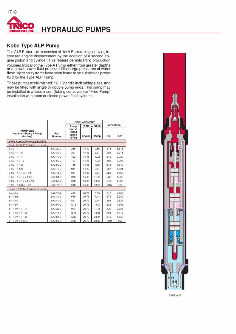
Kobe Type ALP PumpThe ALP Pump is anextension of the A Pump design, having in-creased engine displacement by the addition of a second en-gine piston and cylinder. This feature permits lifting production
volumes typical of the Type A Pump either from greater depthsor at lower power fluid pressure. Discharge pressures of waterflood injectionsystems havebeen foundto be suitable as powerfluid for the Type ALP Pump.
These pumps arefurnished in2-1/2and3 inch tubingsizes, andmay be fitted with single or double pump ends.This pump maybe installed in a fixed insert (tubing conveyed) or “Free Pump”installation with open or closed power fluid systems.
HYDRAULIC PUMPS
TYPE ALP

7/14/2019 Equipos Trico
http://slidepdf.com/reader/full/equipos-trico 19/44
1719
HYDRAULIC PUMPS
UnitModel P/E
StrokeLength(inches) SPM
DISPLACEMENT Approx.
PumpLength(inches)
Approx.
PumpWeight(lbs.)
Per SPM At Rated Speed
Engine Pump Engine Pump
Fits in 2-3/8" O.D. Tubing or Larger
F201311 .71 22 68 4.20 3.00 286 204 151.47 110
F201313 1.00 22 68 4.20 4.20 286 286 151.47 104
F201611 .47 22 68 6.40 3.00 435 204 150.94 70
F201613 .66 22 68 6.40 4.20 435 286 153.28 90
FEB201613 .66 32 55 9.40 6.20 517 340 186.80 80
FEB201616 1.00 32 55 9.40 9.40 517 517 186.80 145
330-201612 .63 30 100 8.94 5.45 894 546 217.31 160
530-201615 .89 30 100 8.94 7.86 894 786 217.31 160
Fits in 2-7/8" O.D. Tubing or Larger
F251611 .47 24 65 7.00 3.30 455 214 164.10 111
F251613 .66 24 65 7.00 4.60 455 299 161.54 117
F251616 1.00 24 65 7.00 7.00 455 455 161.54 100
FE251613 .66 34 53 10.00 6.60 530 350 191.54 120
FE251616 1.00 34 53 10.00 10.00 530 530 191.54 116
FE252011 .30 36 51 16.50 4.95 843 252 195.00 133
FE252013 .42 36 51 16.50 6.98 843 355 195.00 160
FE252016 .64 36 51 16.50 10.60 843 540 195.00 160
V25-11-063 .63 15 170 10.00 6.31 1,700 1,073 213.06 140
V25-21-75 .75 15 186 8.38 6.31 1,559 1,174 213.06 142
V25-11-095 .95 15 206 6.66 6.31 1,371 1,300 213.06 160
V25-11-118 1.18 15 225 5.33 6.31 1,199 1,420 213.06 138
348-252012 .40 48 72 22.35 8.73 1,609 629 275.72 212
348-252015 .57 48 72 22.35 12.57 1,609 905 275.72 205
548-252017 .78 48 72 22.35 17.11 1,609 1,232 275.68 189
548-252019 .93 48 72 22.35 20.17 1,609 1,452 275.68 197
Fits in 3-1/2" O.D. Tubing or Larger
548-302419 .643 48 72 32.18 20.17 2,317 1,452 280.91 285
554-302419 .624 54 72 37.31 22.69 2,685 1,634 291.48 291
548-302422 .914 48 72 32.18 28.70 2,317 2,063 281.10 298
554-302423 .961 54 72 37.31 34.96 2,686 2,517 299.10 314
MODEL 220
Oilmaster F- & V-Series andModel 220 Pumps
The Oilmaster F- Series downhole pumps offer a longer strokelength for low to mid-volume production.They will fit in thestan-dard hydraulic bottom hole assembly (2" pump pitch length of79";2-1/2"pump pitch lengthof 105") which allowsinterchange-ability with other manufacturers.
The V and 220 Series pumps weredesigned for higher volumesand deeper depths. They require bottom hole assemblies de-signed toaccept the highervolume.All V and 220 Series pumpsare single-acting pumps,with largerdiameter seats andpoppetdesign valves made of high alloy metal to allow larger flow pas-sages and deeper pumping depths.
7/14/2019 Equipos Trico
http://slidepdf.com/reader/full/equipos-trico 20/44
Hydraulic Jet Pumps
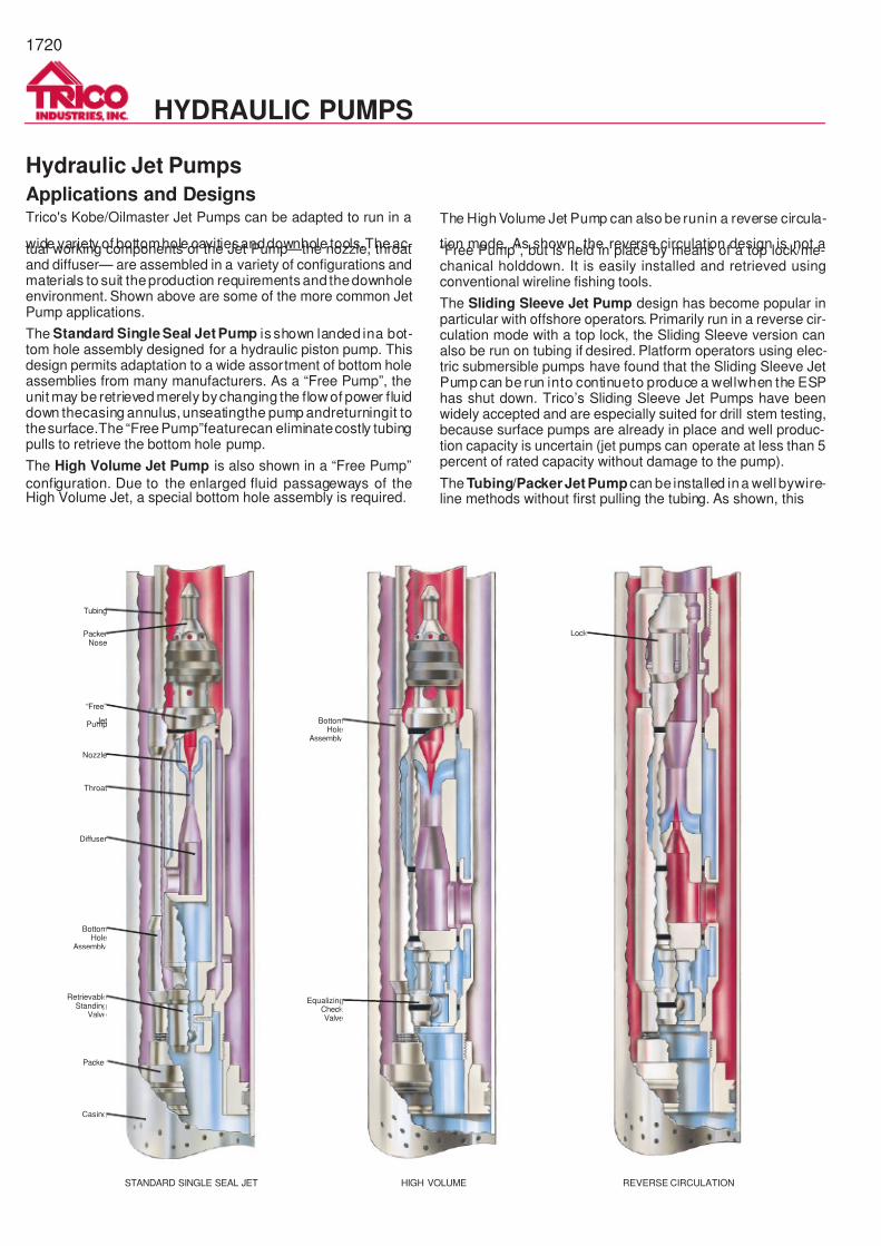
Applications and DesignsTrico's Kobe/Oilmaster Jet Pumps can be adapted to run in a
wide variety of bottomhole cavitiesanddownhole tools.Theac-tual working components of the Jet Pump—the nozzle, throatand diffuser— are assembled in a variety of configurations andmaterials to suit theproduction requirements and thedownholeenvironment. Shown above are some of the more common JetPump applications.
The Standard Single Seal Jet Pump is shown landed ina bot-tom hole assembly designed for a hydraulic piston pump. Thisdesign permits adaptation to a wide assortment of bottom holeassemblies from many manufacturers. As a “Free Pump”, theunit may be retrieved merely bychanging the flow of power fluiddown thecasing annulus,unseatingthe pump andreturningit tothesurface.The “Free Pump”featurecan eliminatecostly tubingpulls to retrieve the bottom hole pump.
The High Volume Jet Pump is also shown in a “Free Pump”
configuration. Due to the enlarged fluid passageways of theHigh Volume Jet, a special bottom hole assembly is required.
The High Volume Jet Pump can also be runin a reverse circula-
tion mode. As shown, the reverse circulation design is not a“Free Pump”, but is held in place by means of a top lock/me-chanical holddown. It is easily installed and retrieved usingconventional wireline fishing tools.
The Sliding Sleeve Jet Pump design has become popular inparticular with offshore operators. Primarily run in a reverse cir-culation mode with a top lock, the Sliding Sleeve version canalso be run on tubing if desired. Platform operators using elec-tric submersible pumps have found that the Sliding Sleeve JetPump can be run into continueto produce a wellwhen the ESPhas shut down. Trico’s Sliding Sleeve Jet Pumps have beenwidely accepted and are especially suited for drill stem testing,because surface pumps are already in place and well produc-tion capacity is uncertain (jet pumps can operate at less than 5percent of rated capacity without damage to the pump).
The Tubing/PackerJet Pump can be installed ina well bywire-line methods without first pulling the tubing. As shown, this
STANDARD SINGLE SEAL JET
Tubing
PackerNose
“Free”
JetPump
Nozzle
Throat
Diffuser
BottomHole
Assembly
RetrievableStanding
Valve
Packer
Casing
HIGH VOLUME
BottomHole
Assembly
EqualizingCheckValve
REVERSE CIRCULATION
Lock
1720
HYDRAULIC PUMPS
7/14/2019 Equipos Trico
http://slidepdf.com/reader/full/equipos-trico 21/44
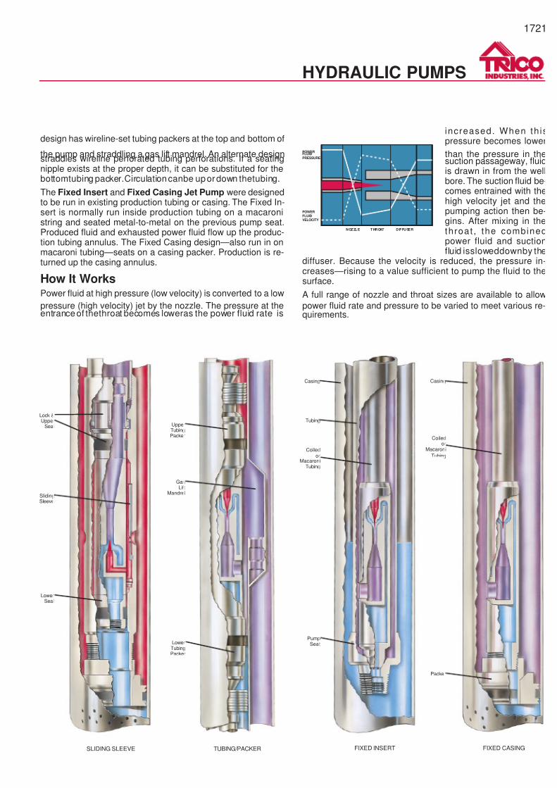
design has wireline-set tubing packers at the top and bottom of
the pump and straddling a gas lift mandrel. An alternate designstraddles wireline perforated tubing perforations. If a seatingnipple exists at the proper depth, it can be substituted for thebottomtubing packer.Circulationcanbe upordown thetubing.
The Fixed Insert and Fixed Casing Jet Pump were designedto be run in existing production tubing or casing. The Fixed In-sert is normally run inside production tubing on a macaronistring and seated metal-to-metal on the previous pump seat.Produced fluid and exhausted power fluid flow up the produc-tion tubing annulus. The Fixed Casing design—also run in onmacaroni tubing—seats on a casing packer. Production is re-turned up the casing annulus.
How It WorksPower fluid at high pressure (low velocity) is converted to a low
pressure (high velocity) jet by the nozzle. The pressure at theentranceof thethroat becomes loweras the power fluid rate is
increased. When th ispressure becomes lower
than the pressure in thesuction passageway, fluidis drawn in from the wellbore. The suction fluid be-comes entrained with thehigh velocity jet and thepumping action then be-gins. After mixing in thethroat , the combinedpower fluid and suctionfluid issloweddownby the
diffuser. Because the velocity is reduced, the pressure in-creases—rising to a value sufficient to pump the fluid to thesurface.
A full range of nozzle and throat sizes are available to allow
power fluid rate and pressure to be varied to meet various re-quirements.
POWERFLUIDPRESSURE
POWERFLUIDVELOCITY
NOZZLE THROAT DIFFUSER
SLIDING SLEEVE
Lock &Upper
Seal
SlidingSleeve
LowerSeal
TUBING/PACKER
UpperTubingPacker
GasLift
Mandrel
LowerTubingPacker
FIXED INSERT
Casing
Tubing
Coiledor
MacaroniTubing
PumpSeat
FIXED CASING
Casing
Coiledor
Macaroni
Tubing
Packer
1721
HYDRAULIC PUMPS
7/14/2019 Equipos Trico
http://slidepdf.com/reader/full/equipos-trico 22/44
1722
HYDRAULIC PUMPS
COILED ORCONVENTIONAL
TUBING
PUMPCAVITY
1-1/4" JET"FREE" PUMP
WELL CASING(OPEN FOR
VENTING GAS)
STANDINGVALVE
TUBINGPACKER
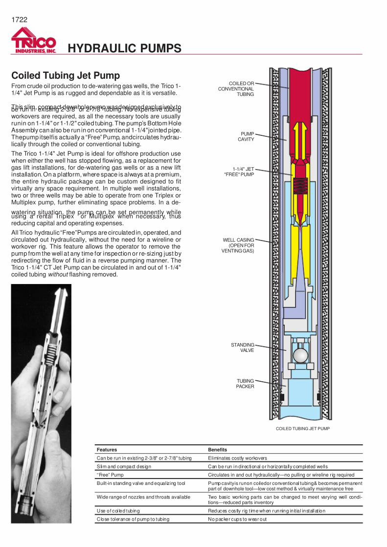
COILED TUBING JET PUMP
Coiled Tubing Jet PumpFrom crude oil production to de-watering gas wells, the Trico 1-1/4" Jet Pump is as rugged and dependable as it is versatile.
This slim, compact downholepump wasdesignedexclusively tobe run in existing 2-3/8" or 2-7/8" tubing. No expensive tubingworkovers are required, as all the necessary tools are usuallyrunin on 1-1/4" or 1-1/2" coiled tubing. The pump’s Bottom HoleAssembly canalso be run in on conventional 1-1/4"jointed pipe.Thepump itselfis actuallya “Free”Pump, andcirculates hydrau-lically through the coiled or conventional tubing.
The Trico 1-1/4" Jet Pump is ideal for offshore production usewhen either the well has stopped flowing, as a replacement forgas lift installations, for de-watering gas wells or as a new liftinstallation. On a platform, where space is always at a premium,the entire hydraulic package can be custom designed to fitvirtually any space requirement. In multiple well installations,two or three wells may be able to operate from one Triplex orMultiplex pump, further eliminating space problems. In a de-
watering situation, the pump can be set permanently whileusing a rental Triplex or Multiplex when necessary, thusreducing capital and operating expenses.
All Trico hydraulic“Free”Pumps are circulated in, operated,andcirculated out hydraulically, without the need for a wireline orworkover rig. This feature allows the operator to remove thepump from the well at any time for inspection or re-sizing just byredirecting the flow of fluid in a reverse pumping manner. TheTrico 1-1/4" CT Jet Pump can be circulated in and out of 1-1/4"coiled tubing without flashing removed.
Features Benefits
Can be run in existing 2-3/8" or 2-7/8" tubing Eliminates costly workovers
Slim and compact design Can be run in directional or horizontally completed wells
“Free” Pump Circulates in and out hydraulically—no pulling or wireline r ig required
Built-in standing valve and equalizing tool Pump cavityis runon coiledor conventional tubing& becomes permanentpart of downhole tool—low cost method & virtually maintenance free
Wide range of nozzles and throats available Two basic working parts can be changed to meet varying well condi-tions—reduced parts inventory
Use of coi led tubing Reduces costly r ig t ime when running init ia l installat ion
Close tolerance of pump to tubing No packer cups to wear out
7/14/2019 Equipos Trico
http://slidepdf.com/reader/full/equipos-trico 23/44
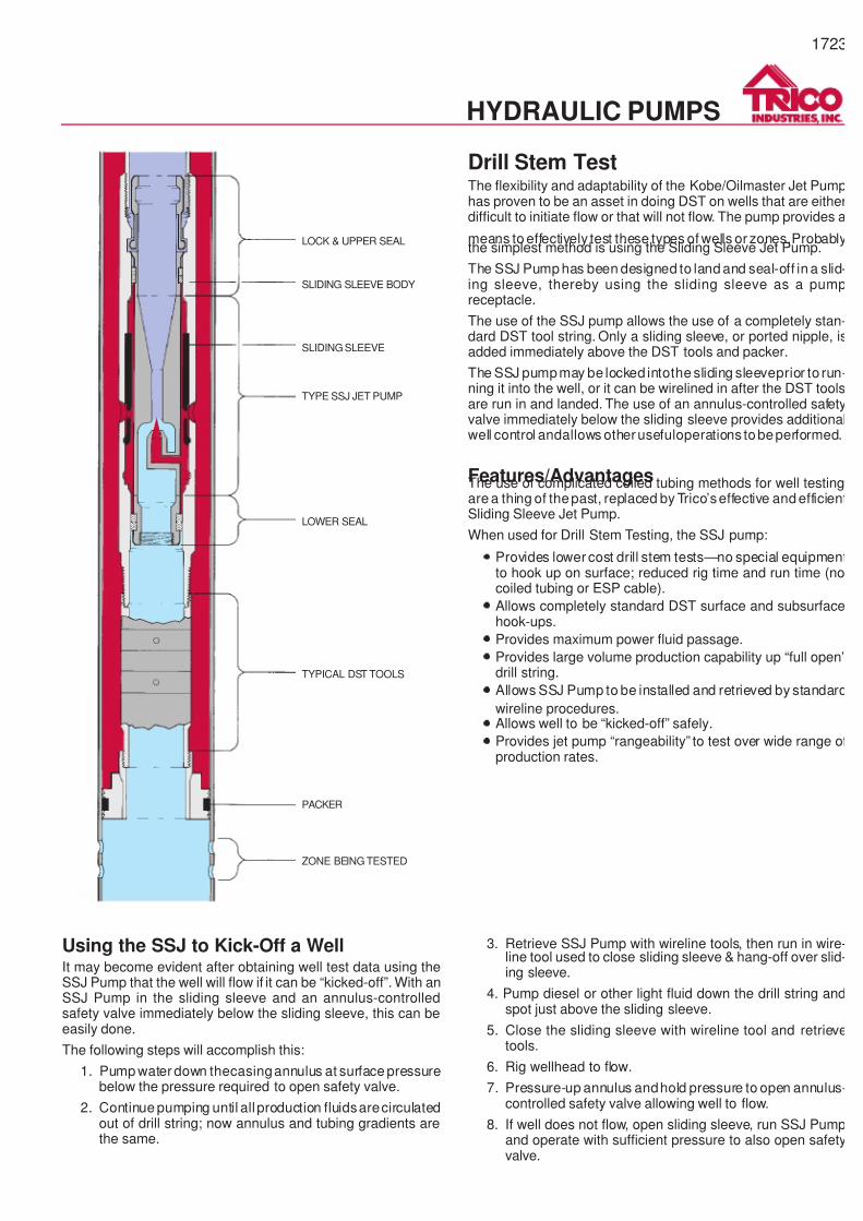
Drill Stem TestThe flexibility and adaptability of the Kobe/Oilmaster Jet Pumphas proven to be an asset in doing DST on wells that are eitherdifficult to initiate flow or that will not flow. The pump provides a
means to effectively test these types of wells or zones.Probablythe simplest method is using the Sliding Sleeve Jet Pump.
The SSJ Pump has been designed to land and seal-off in a slid-ing sleeve, thereby using the sliding sleeve as a pumpreceptacle.
The use of the SSJ pump allows the use of a completely stan-dard DST tool string. Only a sliding sleeve, or ported nipple, isadded immediately above the DST tools and packer.
The SSJ pumpmay be locked intothe sliding sleeveprior to run-ning it into the well, or it can be wirelined in after the DST toolsare run in and landed. The use of an annulus-controlled safetyvalve immediately below the sliding sleeve provides additionalwell control andallows otherusefuloperations tobeperformed.
Features/AdvantagesThe use of complicated coiled tubing methods for well testingare a thing of thepast, replaced by Trico’seffective and efficientSliding Sleeve Jet Pump.
When used for Drill Stem Testing, the SSJ pump:
·
Provides lower cost drill stem tests—no special equipmentto hook up on surface; reduced rig time and run time (nocoiled tubing or ESP cable).
·
Allows completely standard DST surface and subsurfacehook-ups.
·
Provides maximum power fluid passage.
·
Provides large volume production capability up “full open”drill string.
·
Allows SSJ Pump to be installed and retrieved by standard
wireline procedures.·
Allows well to be “kicked-off” safely.
·
Provides jet pump “rangeability” to test over wide range ofproduction rates.
1723
LOCK & UPPER SEAL
SLIDING SLEEVE BODY
SLIDING SLEEVE
TYPE SSJ JET PUMP
LOWER SEAL
TYPICAL DST TOOLS
PACKER
ZONE BEING TESTED
HYDRAULIC PUMPS
Using the SSJ to Kick-Off a WellIt may become evident after obtaining well test data using theSSJ Pump that the well will flow if it can be “kicked-off”. With anSSJ Pump in the sliding sleeve and an annulus-controlledsafety valve immediately below the sliding sleeve, this can beeasily done.
The following steps will accomplish this:
1. Pump water down thecasingannulus at surface pressurebelow the pressure required to open safety valve.
2. Continue pumping until all production fluidsarecirculatedout of drill string; now annulus and tubing gradients arethe same.
3. Retrieve SSJ Pump with wireline tools, then run in wire-line tool used to close sliding sleeve & hang-off over slid-ing sleeve.
4. Pump diesel or other light fluid down the drill string andspot just above the sliding sleeve.
5. Close the sliding sleeve with wireline tool and retrievetools.
6. Rig wellhead to flow.
7. Pressure-up annulus andhold pressure to open annulus-controlled safety valve allowing well to flow.
8. If well does not flow, open sliding sleeve, run SSJ Pumpand operate with sufficient pressure to also open safetyvalve.
7/14/2019 Equipos Trico
http://slidepdf.com/reader/full/equipos-trico 24/44
1724
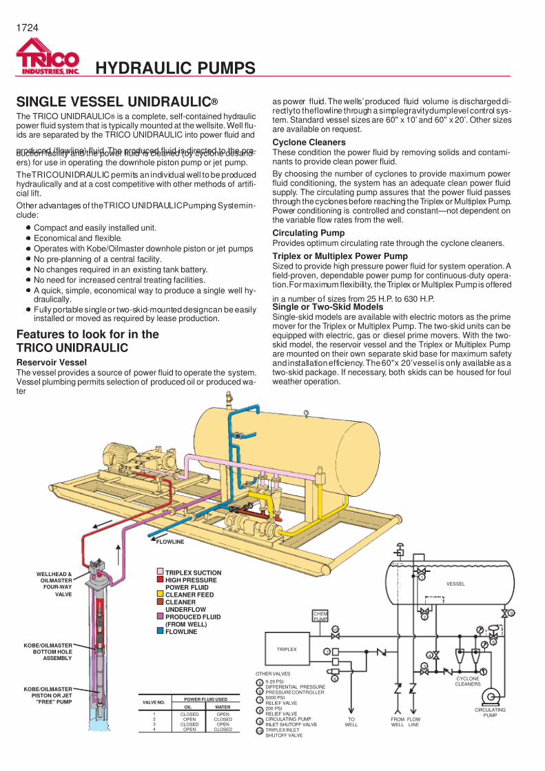
SINGLE VESSEL UNIDRAULIC ®
The TRICO UNIDRAULIC ® is a complete, self-contained hydraulicpower fluid system that is typically mounted at the wellsite.Well flu-ids are separated by the TRICO UNIDRAULIC into power fluid and
produced (flowline) fluid.The produced fluid is directed to the pro-duction facility and the power fluid is cleaned (by cyclone desand-ers) for use in operating the downhole piston pump or jet pump.
TheTRICOUNIDRAULIC permits an individual well tobe producedhydraulically and at a cost competitive with other methods of artifi-cial lift.
Other advantages of theTRICO UNIDRAULICPumping Systemin-clude:
· Compact and easily installed unit.
·
Economical and flexible.
·
Operates with Kobe/Oilmaster downhole piston or jet pumps
· No pre-planning of a central facility.
· No changes required in an existing tank battery.
·
No need for increased central treating facilities.
· A quick, simple, economical way to produce a single well hy-draulically.
·
Fully portable singleor two-skid-mounted designcan be easilyinstalled or moved as required by lease production.
Features to look for in theTRICO UNIDRAULICReservoir VesselThe vessel provides a source of power fluid to operate the system.Vessel plumbing permits selection of produced oil or produced wa-ter
as power fluid.The wells’produced fluid volume is dischargeddi-rectlyto theflowline through a simplegravitydumplevel control sys-tem. Standard vessel sizes are 60" x 10’ and 60" x 20’. Other sizesare available on request.
Cyclone CleanersThese condition the power fluid by removing solids and contami-nants to provide clean power fluid.
By choosing the number of cyclones to provide maximum powerfluid conditioning, the system has an adequate clean power fluidsupply. The circulating pump assures that the power fluid passesthrough thecyclonesbefore reaching theTriplex or Multiplex Pump.Power conditioning is controlled and constant—not dependent onthe variable flow rates from the well.
Circulating PumpProvides optimum circulating rate through the cyclone cleaners.
Triplex or Multiplex Power PumpSized to provide high pressure power fluid for system operation.Afield-proven, dependable power pump for continuous-duty opera-tion.Formaximum flexibility, theTriplex or Multiplex Pumpis offered
in a number of sizes from 25 H.P. to 630 H.P.Single or Two-Skid ModelsSingle-skid models are available with electric motors as the primemover for the Triplex or Multiplex Pump. The two-skid units can beequipped with electric, gas or diesel prime movers. With the two-skid model, the reservoir vessel and the Triplex or Multiplex Pumpare mounted on their own separate skid base for maximum safetyand installationefficiency.The60"x 20’vessel is only available as atwo-skid package. If necessary, both skids can be housed for foulweather operation.
HYDRAULIC PUMPS
CHEMPUMP
TOWELL
FROMWELL
FLOWLINE
CYCLONECLEANERS
CIRCULATINGPUMP
10
7
1
2
4
9
5
3
6
TRIPLEX
VESSEL
OTHER VALVES
5
7
6
8
9
10
0-20 PSIDIFFERENTIAL PRESSUREPRESSURE CONTROLLER5000 PSIRELIEF VALVE200 PSIRELIEF VALVECIRCULATING PUMPINLET SHUTOFF VALVETRIPLEX INLETSHUTOFF VALVE
TRIPLEX SUCTIONHIGH PRESSUREPOWER FLUIDCLEANER FEEDCLEANERUNDERFLOWPRODUCED FLUID(FROM WELL)FLOWLINE
FLOWLINE
WELLHEAD &OILMASTERFOUR-WAY
VALVE
KOBE/OILMASTERBOTTOM HOLE
ASSEMBLY
KOBE/OILMASTERPISTON OR JET
"FREE" PUMP
CLOSEDOPEN
CLOSEDOPEN
OPENCLOSED
OPENCLOSED
POWER FLUID USED
OIL WATERVALVE NO.
1234
7/14/2019 Equipos Trico
http://slidepdf.com/reader/full/equipos-trico 25/44
1725
Production Test UnitsTrico's portable Production Test Unit is a field-proven packagefor testing and evaluating the production levels for a specificwell. By acquiring as much accurate data as possible from thetests,a determination canbe made byTricofieldpersonnel as to
the best type of artificial lift system for that well.These trailer-mounted units are easily transported from onewellsite to another, and are completely self-contained with allnecessary piping, valving and wellhead fittings. Trico Test Unitsset up and tear down easilyand require minimal operator atten-tion.
Because climatic conditions vary around the world, Trico canand has built Test Units to operate in the harsh environment ofAlaska's North Slope and the extreme heat conditions of theMiddle East.
Units are typically located throughout major oil producing areasof theUnitedStatesandareavailable on a rental basis.Contacta Trico representative for information regarding availability inyour area.
HYDRAULIC PUMPS
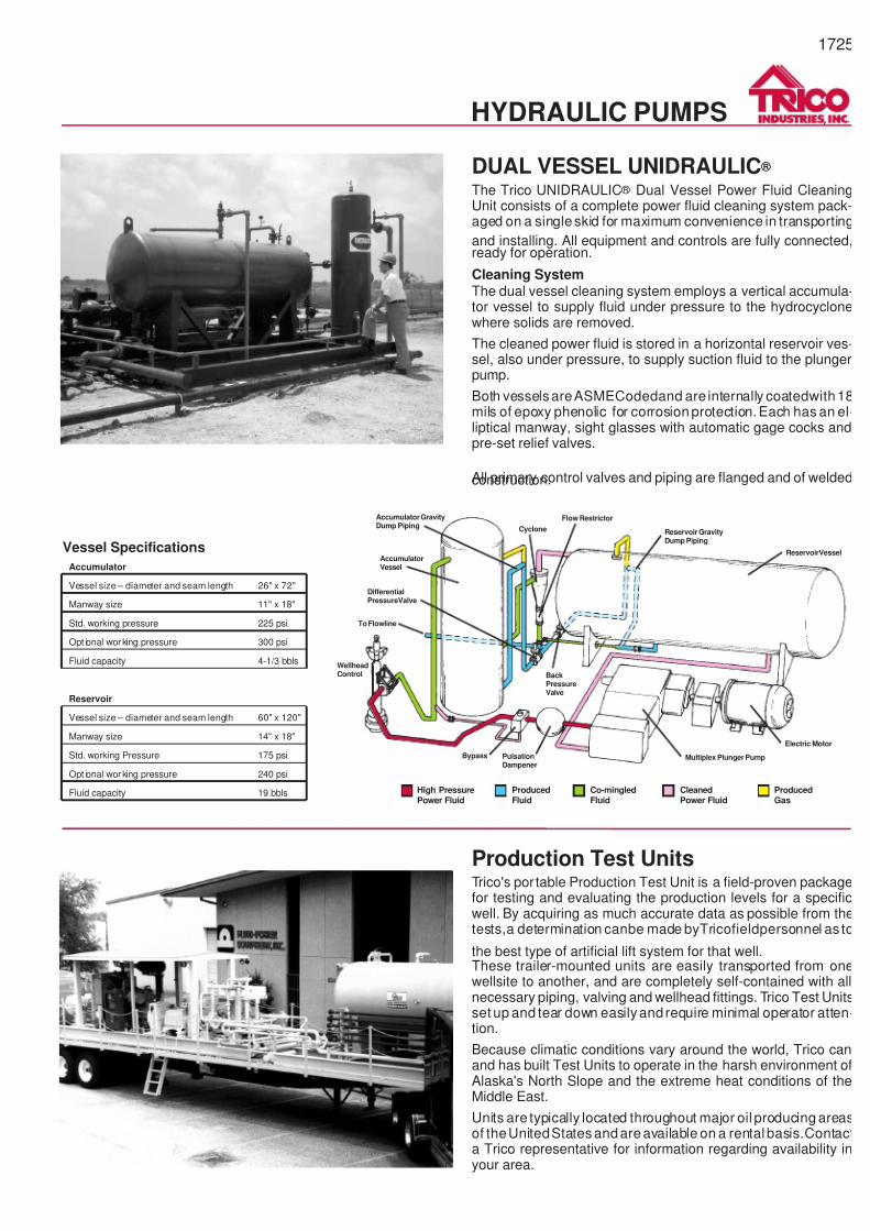
DUAL VESSEL UNIDRAULIC ®
The Trico UNIDRAULIC ® Dual Vessel Power Fluid CleaningUnit consists of a complete power fluid cleaning system pack-aged on a singleskid for maximum convenience in transporting
and installing. All equipment and controls are fully connected,ready for operation.
Cleaning SystemThe dual vessel cleaning system employs a vertical accumula-tor vessel to supply fluid under pressure to the hydrocyclonewhere solids are removed.
The cleaned power fluid is stored in a horizontal reservoir ves-sel, also under pressure, to supply suction fluid to the plungerpump.
Both vesselsareASMECodedand are internally coatedwith18mils of epoxy phenolic for corrosion protection.Each has an el-liptical manway, sight glasses with automatic gage cocks andpre-set relief valves.
All primary control valves and piping are flanged and of weldedconstruction.
Accumulator GravityDump Piping
AccumulatorVessel
DifferentialPressureValve
To Flowline
WellheadControl
Bypass
BackPressureValve
PulsationDampener
Multiplex Plunger Pump
Electric Motor
ReservoirVessel
Reservoir GravityDump Piping
Flow Restrictor
Cyclone
High PressurePower Fluid
ProducedFluid
Co-mingledFluid
CleanedPower Fluid
ProducedGas
Vessel Specifications
Accumulator
Vessel size – diameter and seam length 26" x 72"
Manway size 11" x 18"
Std. working pressure 225 psi
Opt ional working pressure 300 psi
Fluid capacity 4-1/3 bbls
Reservoir
Vessel size – diameter and seam length 60" x 120"
Manway size 14" x 18"
Std. working Pressure 175 psi
Opt ional working pressure 240 psi
Fluid capacity 19 bbls
7/14/2019 Equipos Trico
http://slidepdf.com/reader/full/equipos-trico 26/44
1726
HYDRAULIC PUMPS
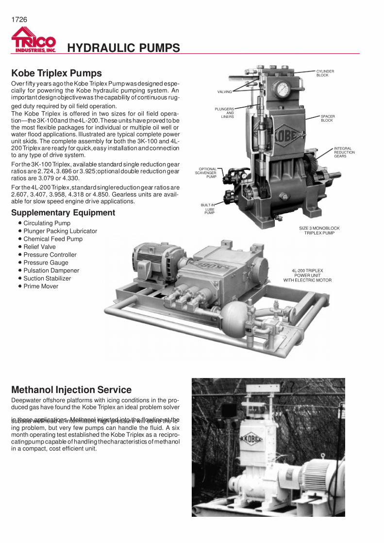
Kobe Triplex PumpsOver fifty years ago theKobe TriplexPumpwasdesigned espe-cially for powering the Kobe hydraulic pumping system. Animportantdesignobjectivewas thecapability of continuous rug-
ged duty required by oil field operation.
The Kobe Triplex is offered in two sizes for oil field opera-tion—the3K-100and the4L-200.These unitshaveproved tobethe most flexible packages for individual or multiple oil well orwater flood applications. Illustrated are typical complete powerunit skids. The complete assembly for both the 3K-100 and 4L-200Triplexare ready for quick,easy installationandconnectionto any type of drive system.
For the 3K-100Triplex, available standard single reduction gearratios are 2.724, 3.696 or 3.925;optionaldouble reduction gearratios are 3.079 or 4.330.
For the4L-200Triplex,standardsinglereductiongear ratiosare2.607, 3.407, 3.958, 4.318 or 4.850. Gearless units are avail-able for slow speed engine drive applications.
Supplementary Equipment·
Circulating Pump
·
Plunger Packing Lubricator
·
Chemical Feed Pump
·
Relief Valve
·
Pressure Controller
·
Pressure Gauge
·
Pulsation Dampener
·
Suction Stabilizer
·
Prime Mover
CYLINDERBLOCK
SPACERBLOCK
INTEGRALREDUCTIONGEARS
BUILT-IN
LUBEPUMP
OPTIONALSCAVENGER
PUMP
PLUNGERSAND
LINERS
VALVING
SIZE 3 MONOBLOCKTRIPLEX PUMP
Methanol Injection ServiceDeepwater offshore platforms with icing conditions in the pro-duced gas have found the Kobe Triplex an ideal problem solver
in these applications. Methanol injected into the flowline at thesubsea wellhead at intermittent high pressure will solve the ic-ing problem, but very few pumps can handle the fluid. A sixmonth operating test established the Kobe Triplex as a recipro-catingpump capable of handling thecharacteristics ofmethanolin a compact, cost efficient unit.
4L-200 TRIPLEXPOWER UNIT
WITH ELECTRIC MOTOR

7/14/2019 Equipos Trico
http://slidepdf.com/reader/full/equipos-trico 27/44
3J-100 3K-100 4J-180 4L-200
Rated BHP 100 100 180 200
Crankshaft Speed — RPM
Maximum Rated 450 450 450 400
Minimum Recommended 100 100 100 100
Maximum Plunger Load 6,800 lb. 8,000 lb. 12,000 lb. 14,000 lb.
Maximum Operating Pressure — PSI
Monoblock (Aluminum Bronze) Fluid End (For Oil or Water Service) 5,000 5,000 — —
3 Cylinder Fluid End (For Oil or Water Service) — 5,000 5,000
Monoblock (Steel) Fluid End (For Oil Service) 5,000 5,000 5,000 5,000
Triplex Suction Pressure — PSI**
Maximum 1,000* 1,000* 1,000* 1,000*
Recommended† 15—75 15—75 15—75 15—75
Minimum† 5—50 5—50 5—50 5—50
Lubrication Oil Capacity — Quarts 14 14 ‡ 53
Weight — Pounds
Triplex Pump Only 1,675 1,675 4,800 4,800
* For any plunger size, discharge pressure must be reduced 5 psi for every 10 psi increase in intake pressure over 50 psi.
** Inlet system piping to Triplex must consider both piping fluid friction and acceleration head to insure proper suction pressure. Consult Hydraulic Institute Standards (Reciprocating Pumps-Ratings).
† Triplex suction pressure (NPSHR) dependent upon fluid end type and valving selected.
‡ With Mechanical Seal – 60 quartsWith Oil Slinger – 45 quarts
Triplex Pumps Specifications
3K-100 TRIPLEX PUMP Maximum Pressure*
PlungerDiameter Displacement/100 RPM
Displacement/450 RPM(Maximum Rated Speed)
3000 PSIHigh Vol. Fluid End
(100 GPM Max. Cap.)
5000 PSIFluid End
(60 GPM Max. Cap.)
Inches mm GPM B/D m3/d GPM B/D m3/d psi MPa psi MPa
3/4 19.0 2.20 79 12.5 10.4 355 56.7 5000 34.5
7/8 22.2 3.12 107 17.0 14.0 481 76.3 5000 34.5
1 25.4 4.08 140 22.2 18.4 630 100.3 5000 34.5
1-1/8 28.6 5.16 177 28.1 23.2 796 126.5 5000 34.5
1-1/4 31.7 6.38 219 34.8 28.7 984 156.4 5000 34.5
1-3/8 34.9 7.72 265 42.1 34.7 1191 189.1 4446 30.7
1-1/2 38.1 9.18 315 50.0 41.3 1416 225.1 3735 25.8
1-5/8 41.3 10.8 369 58.8 48.6 1666 264.9 3174 21.9
1-3/4 44.4 12.5 428 68.1 56.3 1929 306.9 2740 18.9
1-7/8 47.6 14.3 490 77.9 64.4 2206 351.0 2395 16.5
2 50.8 16.3 559 88.8 73.4 2515 400.1 2102 14.5
2-1/8 54.0 18.4 631 100.0 82.8 2839 451.3 1863 12.9
2-1/4 57.1 20.7 710 113.0 93.2 3194 508.0 1655 11.4
2-3/8 60.3 23.0 789 125.0 103.5 3549 564.1 1490 10.3
2-1/2 63.5 25.5 874 139.0 115.2 3934 627.9 1339 9.2
4L-200 TRIPLEX PUMP Maximum Pressure*
PlungerDiameter Displacement/100 RPM
Displacement/400 RPM(Maximum Rated Speed)
5000 PSIFluid End
(115 GPM Max. Cap.)
Inches mm GPM B/D m3/d GPM B/D m3/d psi MPa
1-1/2 38.1 11.5 394 62.7 46.0 1577 251 5000 34.5
1-5/8 41.3 13.5 463 73.6 54.0 1851 294 5000 34.5
1-3/4 44.4 15.6 535 85.0 62.4 2139 340 5000 34.5
1-7/8 47.6 17.9 614 97.6 71.6 2455 390 4309 29.7
2 50.8 20.4 700 111.0 81.6 2798 444 3781 26.1
2-1/8 54.0 23.0 789 125.0 92.0 3154 500 3354 23.1
2-1/4 57.1 25.8 885 141.0 103.2 3538 564 2990 20.6
2-3/8 60.3 28.8 988 157.0 115.2 3950 628 2678 18.5
Displacements are based on 100% volumetric efficiency.
*For 3J & 4J designs, decrease pressure ratings by 15%.
GPM x PSIBHP =
1714 x .90
1727
HYDRAULIC PUMPS
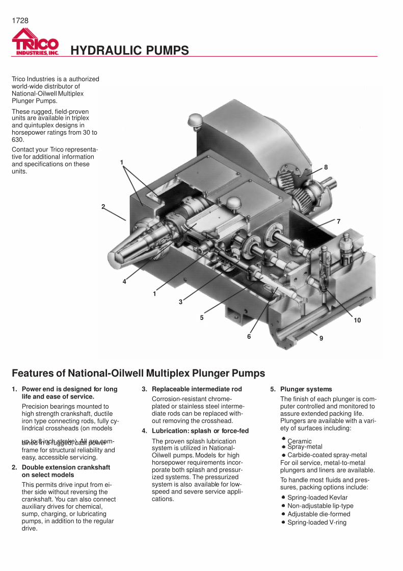
7/14/2019 Equipos Trico
http://slidepdf.com/reader/full/equipos-trico 28/44
1728
HYDRAULIC PUMPS
1
2
3
1
4
6 9
10
7
8
5
1. Power end is designed for longlife and ease of service.
Precision bearings mounted tohigh strength crankshaft, ductileiron type connecting rods, fully cy-lindrical crossheads (on models
up to 8 inch stroke). All are com-bined in a rugged, cast powerframe for structural reliability andeasy, accessible servicing.
2. Double extension crankshafton select models
This permits drive input from ei-ther side without reversing thecrankshaft. You can also connectauxiliary drives for chemical,sump, charging, or lubricatingpumps, in addition to the regulardrive.
Features of National-Oilwell Multiplex Plunger Pumps
3. Replaceable intermediate rod
Corrosion-resistant chrome-plated or stainless steel interme-diate rods can be replaced with-out removing the crosshead.
4. Lubrication: splash or force-fed
The proven splash lubricationsystem is utilized in National-Oilwell pumps. Models for highhorsepower requirements incor-porate both splash and pressur-ized systems. The pressurizedsystem is also available for low-speed and severe service appli-cations.
5. Plunger systems
The finish of each plunger is com-puter controlled and monitored toassure extended packing life.Plungers are available with a vari-ety of surfaces including:
· Ceramic·
Spray-metal
·
Carbide-coated spray-metal
For oil service, metal-to-metalplungers and liners are available.
To handle most fluids and pres-sures, packing options include:
·
Spring-loaded Kevlar
·
Non-adjustable lip-type
·
Adjustable die-formed
·
Spring-loaded V-ring
Trico Industries is a authorizedworld-wide distributor ofNational-Oilwell MultiplexPlunger Pumps.
These rugged, field-provenunits are available in triplexand quintuplex designs inhorsepower ratings from 30 to630.
Contact your Trico representa-tive for additional informationand specifications on theseunits.
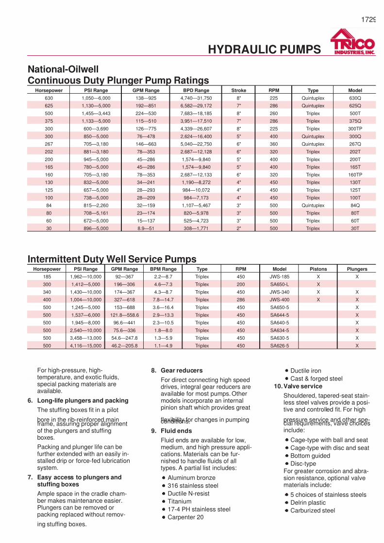
7/14/2019 Equipos Trico
http://slidepdf.com/reader/full/equipos-trico 29/44
1729
For high-pressure, high-temperature, and exotic fluids,special packing materials areavailable.
6. Long-life plungers and packing
The stuffing boxes fit in a pilot
bore in the rib-reinforced mainframe, assuring proper alignmentof the plungers and stuffingboxes.
Packing and plunger life can befurther extended with an easily in-stalled drip or force-fed lubricationsystem.
7. Easy access to plungers andstuffing boxes
Ample space in the cradle cham-ber makes maintenance easier.Plungers can be removed orpacking replaced without remov-
ing stuffing boxes.
8. Gear reducers
For direct connecting high speeddrives, integral gear reducers areavailable for most pumps. Othermodels incorporate an internalpinion shaft which provides great
flexibility for changes in pumpingconditions.
9. Fluid ends
Fluid ends are available for low,medium, and high pressure appli-cations. Materials can be fur-nished to handle fluids of alltypes. A partial list includes:
·
Aluminum bronze
·
316 stainless steel
·
Ductile N-resist
·
Titanium
·
17-4 PH stainless steel
·
Carpenter 20
·
Ductile iron
·
Cast & forged steel
10.Valve service
Shouldered, tapered-seat stain-less steel valves provide a posi-tive and controlled fit. For high
pressure service and other spe-cial requirements, valve choicesinclude:
·
Cage-type with ball and seat
·
Cage-type with disc and seat
·
Bottom guided
·
Disc-type
For greater corrosion and abra-sion resistance, optional valvematerials include:
·
5 choices of stainless steels
·
Delrin plastic
·
Carburized steel
National-OilwellContinuous Duty Plunger Pump Ratings
Horsepower PSI Range GPM Range BPD Range Stroke RPM Type Model
630 1,050—6,000 138—925 4,740—31,750 8" 225 Quintuplex 630Q
625 1,130—5,000 192—851 6,582—29,172 7" 286 Quintuplex 625Q
500 1,455—3,443 224—530 7,683—18,185 8" 260 Triplex 500T
375 1,133—5,000 115—510 3,951—17,510 7" 286 Triplex 375Q
300 600—3,690 126—775 4,339—26,607 8" 225 Triplex 300TP
300 850—5,000 76—478 2,624—16,400 5" 400 Quintuplex 300Q
267 705—3,180 146—663 5,040—22,750 6" 360 Quintuplex 267Q
202 881—3,180 78—353 2,687—12,128 6" 320 Triplex 202T
200 945—5,000 45—286 1,574—9,840 5" 400 Triplex 200T
165 780—5,000 45—286 1,574—9,840 5" 400 Triplex 165T
160 705—3,180 78—353 2,687—12,133 6" 320 Triplex 160TP
130 832—5,000 34—241 1,190—8,272 4" 450 Triplex 130T
125 657—5,000 28—293 984—10,072 4" 450 Triplex 125T
100 738—5,000 28—209 984—7,173 4" 450 Triplex 100T
84 815—2,260 32—159 1,107—5,467 3" 500 Quintuplex 84Q
80 708—5,161 23—174 820—5,978 3" 500 Triplex 80T
60 672—5,000 15—137 525—4,723 3" 500 Triplex 60T
30 896—5,000 8.9—51 308—1,771 2" 500 Triplex 30T
Intermittent Duty Well Service PumpsHorsepower PSI Range GPM Range BPM Range Type RPM Model Pistons Plungers
185 1,962—10,000 92—367 2.2—8.7 Triplex 450 JWS-185 X X
300 1,412—5,000 196—306 4.6—7.3 Triplex 200 SA650-L X
340 1,430—10,000 174—367 4.3—8.7 Triplex 450 JWS-340 X X
400 1,004—10,000 327—618 7.8—14.7 Triplex 286 JWS-400 X X
500 1,245—5,000 153—688 3.6—16.4 Triplex 450 SA650-5 X
500 1,537—6,000 121.8—558.6 2.9—13.3 Triplex 450 SA644-5 X
500 1,945—8,000 96.6—441 2.3—10.5 Triplex 450 SA640-5 X
500 2,540—10,000 75.6—336 1.8—8.0 Triplex 450 SA634-5 X
500 3,458—13,000 54.6—247.8 1.3—5.9 Triplex 450 SA630-5 X
500 4,116—15,000 46.2—205.8 1.1—4.9 Triplex 450 SA626-5 X
HYDRAULIC PUMPS

7/14/2019 Equipos Trico
http://slidepdf.com/reader/full/equipos-trico 30/44
1730
Constant Flow ControllerThe Constant Flow Controller is a high-pressure, hydraulic sys-tem control valve that maintains a constant, preselected rate offlow despite upstream and downstream pressure changes.Flow rates are quickly and easily selected with a handwheelgraduated in barrels per day.
The Constant Flow Controller is designed for operating pres-sures up to 5,000 psi, for continuous service year-in and year-out, and installation in any position. It is adaptable to crude oil,treated water, sea water, oil field brines, or fluids of other vis-cosities.
Available in threesizes for maximum flow rates of 800, 1600 and3200 BPD.
Oilmaster Constant Flow ControllerThe Oilmaster 280-390 Constant Flow Control Valve is widelyused as a control valve for subsurface hydraulic pumping sys-
tems. It delivers power fluid–either oil or water, up to 5,000PSIG–at thepre-selectedconstantrate regardless of variationsin inlet or dischargepressures. It serves to stabilizeoperationofthe downhole hydraulic pump.
The flange connections on this valve make it adaptable to “in-line” applications or for multi-well manifolds. This valve is ratedto 2400 BPD. The 280-391 valve is rated to 1000 BPD.
Pressure ControllerThe Trico/Kobe Pressure Controller is a high-pressure, hydrau-lic system control valve designed for maintaining a constant,preselected upstream pressure regardless of changes in vol-ume. It responds quickly to changing volume requirements andhas controlled dampening to prevent “hunting” and snap clos-ing. The Pressure Controller can be used for a wide variety ofliquids — crude oil, treated water, seawaterand oilfieldbrines.
Trico/Kobe Pressure Controllers maintain back pressures up to5,000 psi.A scale graduated in psi allows quick and easy selec-
tion of pressure. Units are available in complete manifoldsystems or as stand-alone units with welding flanges orthreaded flanges.
CONSTANT FLOW CONTROLLER
PRESSURE CONTROLLER
HYDRAULIC PUMPS
CONSTANT FLOWCONTROLLER
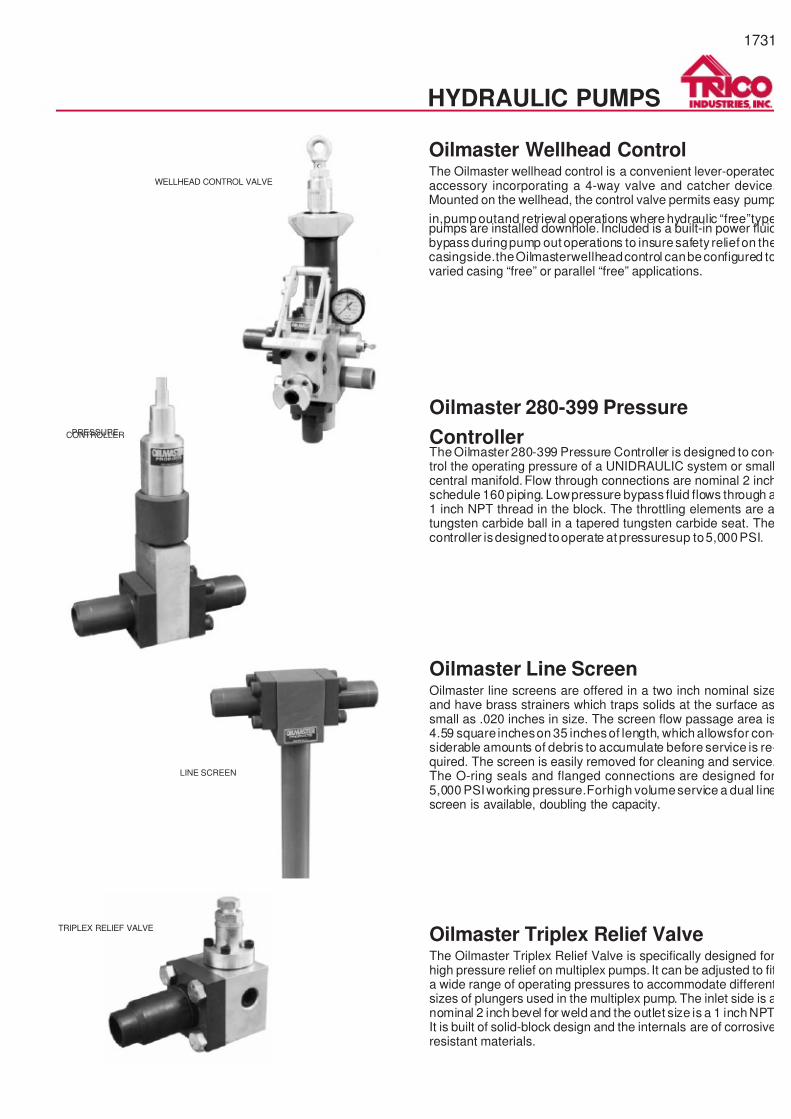
7/14/2019 Equipos Trico
http://slidepdf.com/reader/full/equipos-trico 31/44
1731
HYDRAULIC PUMPS
LINE SCREEN
TRIPLEX RELIEF VALVE
Oilmaster Wellhead ControlThe Oilmaster wellhead control is a convenient lever-operatedaccessory incorporating a 4-way valve and catcher device.Mounted on the wellhead, the control valve permits easy pump
in,pump outand retrieval operations where hydraulic “free”typepumps are installed downhole. Included is a built-in power fluidbypass duringpump out operations to insuresafety reliefon thecasingside.theOilmasterwellheadcontrol canbeconfigured tovaried casing “free” or parallel “free” applications.
Oilmaster Line ScreenOilmaster line screens are offered in a two inch nominal sizeand have brass strainers which traps solids at the surface assmall as .020 inches in size. The screen flow passage area is4.59 square incheson 35 inchesof length, which allowsfor con-siderable amounts of debris to accumulate before service is re-quired. The screen is easily removed for cleaning and service.The O-ring seals and flanged connections are designed for5,000 PSIworking pressure.Forhigh volumeservice a dual linescreen is available, doubling the capacity.
Oilmaster 280-399 Pressure
ControllerThe Oilmaster 280-399 Pressure Controller is designed to con-trol the operating pressure of a UNIDRAULIC system or smallcentral manifold. Flow through connections are nominal 2 inchschedule 160 piping. Lowpressure bypass fluid flows through a1 inch NPT thread in the block. The throttling elements are atungsten carbide ball in a tapered tungsten carbide seat. Thecontroller isdesigned tooperate at pressuresup to5,000PSI.
Oilmaster Triplex Relief ValveThe Oilmaster Triplex Relief Valve is specifically designed forhigh pressure relief on multiplex pumps. It can be adjusted to fita wide range of operating pressures to accommodate differentsizes of plungers used in the multiplex pump. The inlet side is anominal 2 inch bevel for weld and the outlet size is a 1 inch NPT.It is built of solid-block design and the internals are of corrosiveresistant materials.
WELLHEAD CONTROL VALVE
PRESSURECONTROLLER
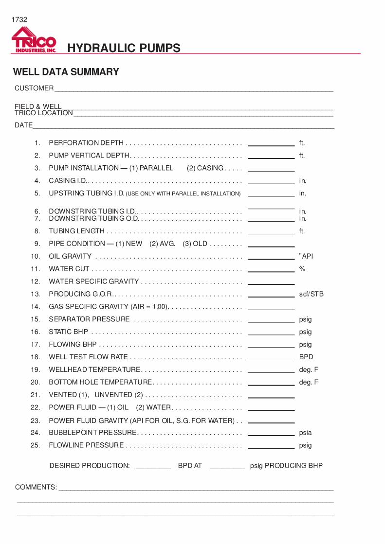
7/14/2019 Equipos Trico
http://slidepdf.com/reader/full/equipos-trico 32/44
1732
HYDRAULIC PUMPS
1. PERFORATION DEPTH . . . . . . . . . . . . . . . . . . . . . . . . . . . . . . . ft.
2. PUMP VERTICAL DEPTH. . . . . . . . . . . . . . . . . . . . . . . . . . . . . . ft.
3. PUMP INSTALLATION — (1) PARALLEL (2) CASING . . . . .
4. CASING I.D.. . . . . . . . . . . . . . . . . . . . . . . . . . . . . . . . . . . . . . . . . in.
5. UPSTRING TUBING I.D. (USE ONLY WITH PARALLEL INSTALLATION) in.
6. DOWNSTRING TUBING I.D.. . . . . . . . . . . . . . . . . . . . . . . . . . . . in.7. DOWNSTRING TUBING O.D. . . . . . . . . . . . . . . . . . . . . . . . . . . . in.
8. TUBING LENGTH . . . . . . . . . . . . . . . . . . . . . . . . . . . . . . . . . . . . ft.
9. PIPE CONDITION — (1) NEW (2) AVG. (3) OLD . . . . . . . . .
10. OIL GRAVITY . . . . . . . . . . . . . . . . . . . . . . . . . . . . . . . . . . . . . . . ° API
11. WATER CUT . . . . . . . . . . . . . . . . . . . . . . . . . . . . . . . . . . . . . . . . %
12. WATER SPECIFIC GRAVITY . . . . . . . . . . . . . . . . . . . . . . . . . . .
13. PRODUCING G.O.R.. . . . . . . . . . . . . . . . . . . . . . . . . . . . . . . . . . scf/STB
14. GAS SPECIFIC GRAVITY (AIR = 1.00). . . . . . . . . . . . . . . . . . . .
15. SEPARATOR PRESSURE . . . . . . . . . . . . . . . . . . . . . . . . . . . . . psig
16. STATIC BHP . . . . . . . . . . . . . . . . . . . . . . . . . . . . . . . . . . . . . . . . psig
17. FLOWING BHP . . . . . . . . . . . . . . . . . . . . . . . . . . . . . . . . . . . . . . psig
18. WELL TEST FLOW RATE . . . . . . . . . . . . . . . . . . . . . . . . . . . . . . BPD
19. WELLHEAD TEMPERATURE. . . . . . . . . . . . . . . . . . . . . . . . . . . deg. F
20. BOTTOM HOLE TEMPERATURE. . . . . . . . . . . . . . . . . . . . . . . . deg. F
21. VENTED (1), UNVENTED (2) . . . . . . . . . . . . . . . . . . . . . . . . . .
22. POWER FLUID — (1) OIL (2) WATER. . . . . . . . . . . . . . . . . . .
23. POWER FLUID GRAVITY (API FOR OIL, S.G. FOR WATER) . .
24. BUBBLEPOINT PRESSURE. . . . . . . . . . . . . . . . . . . . . . . . . . . . psia
25. FLOWLINE PRESSURE . . . . . . . . . . . . . . . . . . . . . . . . . . . . . . . psig
WELL DATA SUMMARY
CUSTOMER_________________________________________________________________________
FIELD & WELL_______________________________________________________________________ TRICO LOCATION____________________________________________________________________
DATE_______________________________________________________________________________
DESIRED PRODUCTION: _________ BPD AT _________ psig PRODUCING BHP
COMMENTS: ________________________________________________________________________
___________________________________________________________________________________
___________________________________________________________________________________
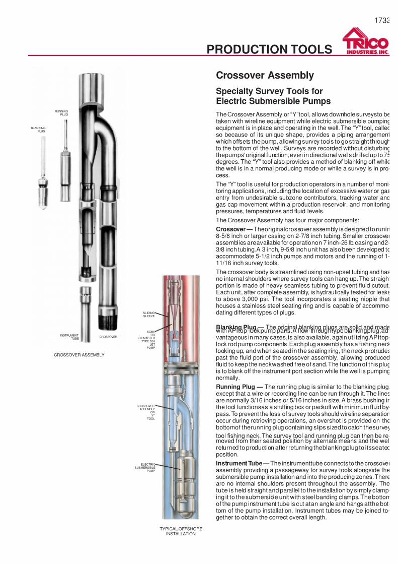
7/14/2019 Equipos Trico
http://slidepdf.com/reader/full/equipos-trico 33/44
1733
TheCrossover Assembly, or “Y”tool, allows downholesurveysto betaken with wireline equipment while electric submersible pumpingequipment is in place and operating in the well.The “Y” tool, calledso because of its unique shape, provides a piping arrangementwhich offsets thepump,allowingsurvey tools to go straight throughto the bottom of the well. Surveys are recorded without disturbingthepumps' original function,even indirectional wellsdrilled up to75degrees. The “Y” tool also provides a method of blanking off whilethe well is in a normal producing mode or while a survey is in pro-cess.
The “Y” tool is useful for production operators in a number of moni-toring applications, including the location of excessive water or gasentry from undesirable subzone contributors, tracking water andgas cap movement within a production reservoir, and monitoringpressures, temperatures and fluid levels.
The Crossover Assembly has four major components:
Crossover — Theoriginalcrossoverassembly isdesigned torunin8-5/8 inch or larger casing on 2-7/8 inch tubing.Smaller crossoverassemblies areavailable for operationon 7 inch-26 lb.casing and2-3/8 inch tubing.A 3 inch, 9-5/8 inchunit has alsobeen developed toaccommodate 5-1/2 inch pumps and motors and the running of 1-11/16 inch survey tools.
The crossover body is streamlined using non-upset tubing and hasno internal shoulders where survey tools can hang up.The straightportion is made of heavy seamless tubing to prevent fluid cutout.Each unit, after complete assembly, is hydraulically tested for leaksto above 3,000 psi. The tool incorporates a seating nipple thathouses a stainless steel seating ring and is capable of accommo-dating different types of plugs.
Crossover Assembly
Blanking Plug — The original blanking plugs are solid and madewith APItop-lock pump parts.A flow-throughtypeblankingplug,ad-vantageous in many cases,is also available,again utilizingAPItop-lock rodpump components.Eachplug assembly hasa fishing necklooking up, andwhen seated in theseating ring, theneck protrudespast the fluid port of the crossover assembly, allowing producedfluid to keep the neckwashed free of sand. The function of this plugis to blank off the instrument port section while the well is pumpingnormally.
Running Plug — The running plug is similar to the blanking plug,except that a wire or recording line can be run through it.The linesare normally 3/16 inches or 5/16 inches in size. A brass bushing inthe tool functionsas a stuffing box or packoff with minimum fluid by-pass.To prevent the loss of survey tools should wireline separationoccur during retrieving operations, an overshot is provided on thebottomof therunning plug containing slips sized tocatch thesurvey
tool fishing neck.The survey tool and running plug can then be re-moved from their seated position by alternate means and the wellreturned toproduction after returning theblankingplug to itsseatedposition.
Instrument Tube— The instrumenttube connects to thecrossoverassembly providing a passageway for survey tools alongside thesubmersible pump installation and into the producing zones.Thereare no internal shoulders present throughout the assembly. Thetube is held straightand parallel to the installation by simply clamp-ing it to thesubmersible unit with steel banding clamps.Thebottomof the pump instrument tube is cut atan angle and hangs atthe bot-tom of the pump installation. Instrument tubes may be joined to-gether to obtain the correct overall length.
Specialty Survey Tools forElectric Submersible Pumps
CROSSOVER ASSEMBLY
RUNNINGPLUG
BLANKINGPLUG
INSTRUMENTTUBE
CROSSOVER
TYPICAL OFFSHOREINSTALLATION
SLIDINGSLEEVE
KOBEOR
OILMASTERTYPE SSJ
JETPUMP
CROSSOVERASSEMBLY
OR“Y”
TOOL
PRODUCTION TOOLS
ELECTRICSUBMERSIBLE
PUMP
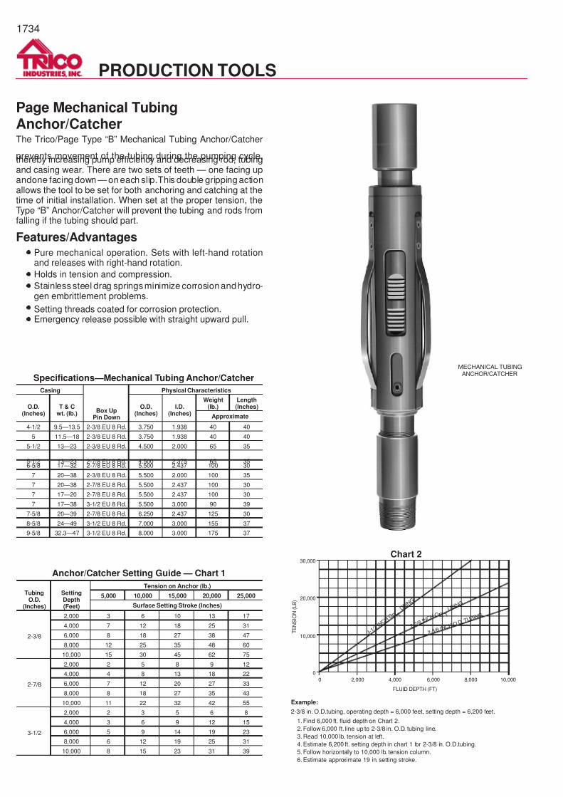
7/14/2019 Equipos Trico
http://slidepdf.com/reader/full/equipos-trico 34/44
1734
Page Mechanical TubingAnchor/CatcherThe Trico/Page Type “B” Mechanical Tubing Anchor/Catcher
prevents movement of the tubing during the pumping cycle,thereby increasing pump efficiency and decreasing rod, tubingand casing wear. There are two sets of teeth — one facing upandone facing down — on each slip.This double gripping actionallows the tool to be set for both anchoring and catching at thetime of initial installation. When set at the proper tension, theType “B” Anchor/Catcher will prevent the tubing and rods fromfalling if the tubing should part.
Features/Advantages·
Pure mechanical operation. Sets with left-hand rotationand releases with right-hand rotation.
·
Holds in tension and compression.
·
Stainless steel drag springsminimize corrosionandhydro-gen embrittlement problems.
· Setting threads coated for corrosion protection.·
Emergency release possible with straight upward pull.
Casing
Box UpPin Down
Physical Characteristics
O.D.(Inches)
T & Cwt. (lb.)
O.D.(Inches)
I.D.(Inches)
Weight(lb.)
Length(Inches)
Approximate
4-1/2 9.5—13.5 2-3/8 EU 8 Rd. 3.750 1.938 40 40
5 11.5—18 2-3/8 EU 8 Rd. 3.750 1.938 40 40
5-1/2 13—23 2-3/8 EU 8 Rd. 4.500 2.000 65 35
5-1/2 13—23 2-7/8 EU 8 Rd. 4.500 2.375 65 356-5/8 17—32 2-7/8 EU 8 Rd. 5.500 2.437 100 30
7 20—38 2-3/8 EU 8 Rd. 5.500 2.000 100 35
7 20—38 2-7/8 EU 8 Rd. 5.500 2.437 100 30
7 17—20 2-7/8 EU 8 Rd. 5.500 2.437 100 30
7 17—38 3-1/2 EU 8 Rd. 5.500 3.000 90 39
7-5/8 20—39 2-7/8 EU 8 Rd. 6.250 2.437 125 30
8-5/8 24—49 3-1/2 EU 8 Rd. 7.000 3.000 155 37
9-5/8 32.3—47 3-1/2 EU 8 Rd. 8.000 3.000 175 37
TubingO.D.
(Inches)
SettingDepth(Feet)
Tension on Anchor (lb.)
5,000 10,000 15,000 20,000 25,000
Surface Setting Stroke (Inches)
2-3/8
2,000 3 6 10 13 17
4,000 7 12 18 25 31
6,000 8 18 27 38 47
8,000 12 25 35 48 60
10,000 15 30 45 62 75
2-7/8
2,000 2 5 8 9 12
4,000 4 8 13 18 22
6,000 7 12 20 27 33
8,000 8 18 27 35 43
10,000 11 22 32 42 55
3-1/2
2,000 2 3 5 6 8
4,000 3 6 9 12 15
6,000 5 9 14 19 23
8,000 6 12 19 25 31
10,000 8 15 23 31 39
Specifications—Mechanical Tubing Anchor/Catcher
Anchor/Catcher Setting Guide — Chart 1
0
0
2,000 4,000 6,000 8,000 10,000
3 - 1 / 2
I N C H
O. D. T
U B I N G
2 - 7 / 8 I
N C H O. D. T
U B I N G
2 - 3 / 8 I N
C H O. D
. T U B I N
G
30,000
20,000
10,000
FLUID DEPTH (FT)
TENSION
(LB)
Example:
2-3/8 in. O.D.tubing, operating depth = 6,000 feet, setting depth = 6,200 feet.
1. Find 6,000 ft. fluid depth on Chart 2.
2. Follow 6,000 ft. line up to 2-3/8 in. O.D. tubing line.
3. Read 10,000 lb. tension at left.
4. Estimate 6,200 ft. setting depth in chart 1 for 2-3/8 in. O.D.tubing.
5. Follow horizontally to 10,000 lb. tension column.
6. Estimate approximate 19 in. setting stroke.
Chart 2
MECHANICAL TUBINGANCHOR/CATCHER
PRODUCTION TOOLS
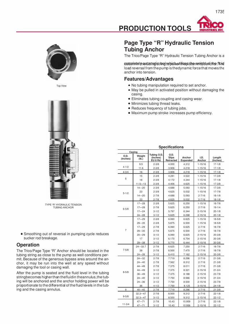
7/14/2019 Equipos Trico
http://slidepdf.com/reader/full/equipos-trico 35/44
1735
Page Type “R” Hydraulic TensionTubing AnchorThe Trico/Page Type “R” Hydraulic Tension Tubing Anchor is a
completely automatic tool which utilizes the weight of the fluidcolumnin thetubing string topower thepiston in theanchor.Theload reversal from thepump is thedynamic force that moves theanchor into tension.
Features/Advantages·
No tubing manipulation required to set anchor.
·
May be pulled in activated position without damaging thecasing.
·
Eliminates tubing coupling and casing wear.
·
Minimizes tubing thread leaks.
·
Reduces frequency of tubing jobs.
·
Maximum pump stroke increases pump efficiency.
·
Smoothing out of reversal in pumping cycle reducessucker rod breakage.
OperationThe Trico/Page Type “R” Anchor should be located in thetubing string as close to the pump as well conditions per-mit. Because of the generous bypass area around the an-chor, it may be run into the well at any speed withoutdamaging the tool or casing wall.
After the pump is seated and the fluid level in the tubingstringbecomes higher than thefluidin theannulus,the tub-ing will be anchored and the anchor holding power will beproportionate to thedifferential of the fluid levels in the tub-ing and the casing annulus.
CasingTubing O.D.
(Inches)EU 8 Rd.
O.D.Slips
RetractedAnchor
ExpandedI.D.
AnchorLength(Inches)
O.D.(Inches)
Weight(lb.)
4-1/29.5 2-3/8 4.000 4.312 1-15/16 17-1/8
11.6 2-3/8 3.906 4.218 1-15/16 17-1/8
4-3/4 16 2-3/8 3.906 4.218 1-15/16 17-1/8
515 2-3/8 4.281 4.522 1-15/16 17-3/8
18 2-3/8 4.172 4.344 1-15/16 17-1/8
11.5—13 2-3/8 4.406 4.625 1-15/16 17-3/8
5-1/2
14—20 2-3/8 4.688 5.093 1-15/16 17-3/8
23 2-3/8 4.625 5.032 1-15/16 17-7/8
14—20 2-7/8 4.688 5.093 2-7/16 18-1/8
23 2-7/8 4.625 5.032 2-7/16 18-1/8
6-5/8
17—28 2-3/8 5.625 6.250 1-15/16 18-7/8
17—28 2-7/8 5.625 6.250 2-7/16 19-1/4
17—24 3-1/2 5.797 6.344 2-15/16 20-1/8
24—28 3-1/2 5.625 6.298 2-15/16 20-1/8
7
17—29 2-3/8 6.060 6.625 1-15/16 18-5/8
29—35 2-3/8 5.875 6.500 1-15/16 18-5/8
17—29 2-7/8 6.060 6.625 2-7/16 18-7/8
29—35 2-7/8 5.875 6.500 2-7/16 18-7/8
20—29 3-1/2 6.060 6.625 2-15/16 20-3/8
17 3-1/2 6.170 6.704 2-15/16 20-3/8
29—38 3-1/2 5.770 6.444 2-15/16 20-3/8
7-5/8
24—33.7 2-7/8 6.625 7.250 2-7/16 18-7/8
39 2-7/8 6.500 7.470 2-7/16 18-7/8
24—39 3-1/2 6.410 7.162 2-15/16 20-3/8
8-5/8
24—32 2-7/8 7.719 8.296 2-7/16 21-3/8
24—40 2-7/8 7.562 8.312 2-7/16 21-3/8
44—49 2-7/8 7.375 8.011 2-7/16 21-3/8
44—49 3-1/2 7.375 8.321 2-15/16 21-3/4
36—49 3-1/2 7.375 8.188 2-15/16 23-7/8
24—40 3-1/2 7.750 8.566 2-15/16 21-3/4
24—36 3-1/2 7.750 8.500 2-15/16 23-7/8
36 4-1/2 7.750 8.125 3-15/16 24-1/8
9 40—45 2-7/8 7.719 8.296 2-7/16 21-3/8
9-5/832.3—47 2-7/8 8.500 9.312 2-7/16 22-1/8
32.3—47 3-1/2 8.500 9.312 2-15/16 22-1/2
11-3/447—71 2-7/8 10.43 10.959 2-7/16 22-1/8
47—71 3-1/2 10.43 10.956 2-15/16 22-1/2
Specifications
TYPE “R” HYDRAULIC TENSIONTUBING ANCHOR
PRODUCTION TOOLS
Top View
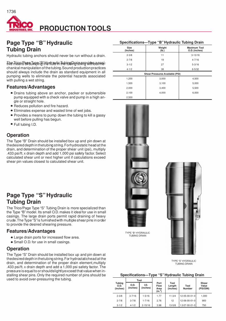
7/14/2019 Equipos Trico
http://slidepdf.com/reader/full/equipos-trico 36/44
1736
Page Type “B” HydraulicTubing DrainHydraulic tubing anchors should never be run without a drain.
TheTrico/PageType “B”HydraulicTubingDrain provides a posi-tive means of dumping the fluid in the tubing string without me-chanical manipulation of the tubing.Sound productionpracticesshould always include the drain as standard equipment in allpumping wells to eliminate the potential hazards associatedwith pulling a wet string.
Features/Advantages·
Drains tubing above an anchor, packer or submersiblepump equipped with a check valve and pump in a high an-gle or straight hole.
·
Reduces pollution and fire hazard.
·
Eliminates expense and wasted time of wet jobs.
·
Provides a means to pump down the tubing to kill a gassywell before pulling has begun.
· Full tubing I.D.
OperationThe Type “B” Drain should be installed box up and pin down atthedesireddepth in thetubing string.Forhydrostatic head at thedrain, and determination of the proper shear unit (psi), multiply.433 psi/ft. x drain depth and add 1,000 psi safety factor. Selectcalculated shear unit or next higher unit if calculations exceedshear pin values closest to calculated shear unit.
Page Type “S” HydraulicTubing DrainThe Trico/Page Type “S” Tubing Drain is more specialized thanthe Type “B” model. Its small O.D.makes it ideal for use in smallcasings. The large drain ports permit rapid draining of heavycrude.The Type “S”is furnishedwith multiple shear pins in orderto provide the desired shearing pressure.
Features/Advantages·
Large drain ports for increased flow area.
·
Small O.D. for use in small casings.
OperationThe Type “S” Drain should be installed box up and pin down atthedesireddepth in thetubing string.For hydrostatichead at thedrain, and determination of the proper drain element,multiply.433 psi/ft. x drain depth and add a 1,000 psi safety factor. Thepressure isequal toorshouldslightlyexceed that valuewhen in-stalling shear pins. Only the required number of pins should beused to avoid over-pressuring the tubing.
Size(Inches)
Weight(lb.)
Maximum ToolO.D. (inches)
2-3/8 11 3-13/16
2-7/8 19 4-7/16
3-1/2 27 5-3/16
4-1/2 38 6-5/32
Shear Pressures Available (PSI)
1,200 3,000 4,500
1,500 3,100 5,000
2,000 3,400 5,500
2,100 4,000 6,000
2,500
TubingO.D.
(inches)
ToolPortFlowArea(in.2)
ToolLength(inches)
ToolNumber
ShearValue
(PSI/DIN)
O.D.(inches)
I.D.(inches)
2-3/8 3-7/16 1-5/16 1.77 11-3/4 12-05-00-01-0 1,000
2-7/8 3-7/8 1-7/16 2.76 12 12-06-00-01-0 900
3-1/2 4-1/2 2-15/16 3.98 13-5/8 1 2-07-00-01-0 750
Specifications—Type “B”Hydraulic Tubing Drain
Specifications—Type “S”Hydraulic Tubing Drain
TYPE “B“ HYDRAULICTUBING DRAIN
TYPE “S” HYDRAULICTUBING DRAIN
PRODUCTION TOOLS
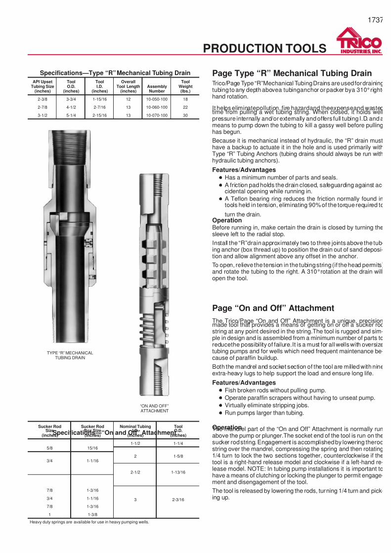
7/14/2019 Equipos Trico
http://slidepdf.com/reader/full/equipos-trico 37/44
1737
Page Type “R” Mechanical Tubing DrainTrico/Page Type“R”Mechanical TubingDrains areusedfordrainingtubing toany depthabovea tubinganchor or packer bya 310°right-hand rotation.
It helps eliminatepollution, fire hazardand theexpenseand wastedtime from pulling a wet tubing string. When closed, it holds wellpressure internally and/or externally andoffers full tubing I.D. andameans to pump down the tubing to kill a gassy well before pullinghas begun.
Because it is mechanical instead of hydraulic, the “R” drain musthave a backup to actuate it in the hole and is used primarily withType “R” Tubing Anchors (tubing drains should always be run withhydraulic tubing anchors).
Features/Advantages
·
Has a minimum number of parts and seals.
· A friction padholds thedrain closed, safeguarding against ac-cidental opening while running in.
·
A Teflon bearing ring reduces the friction normally found intools held in tension, eliminating 90%of the torque required to
turn the drain.OperationBefore running in, make certain the drain is closed by turning thesleeve left to the radial stop.
Install the “R”drainapproximately two to three jointsabove the tub-ing anchor (box thread up) to position the drain out of sand deposi-tion and allow alignment above any offset in the anchor.
To open, relieve the tension in the tubingstring(if thehead permits)and rotate the tubing to the right. A 310°rotation at the drain willopen the tool.
Page “On and Off” Attachment
The Trico/Page “On and Off” Attachment is a unique, precisionmade tool that provides a means of getting on or off a sucker rodstring at any point desired in the string.The tool is rugged and sim-ple in design and is assembled from a minimum number of parts toreducethe possibility of failure.It is a must for all wellswith oversizetubing pumps and for wells which need frequent maintenance be-cause of paraffin buildup.
Both the mandrel and socket section of the tool are milled with nineextra-heavy lugs to help support the load and ensure long life.
Features/Advantages
· Fish broken rods without pulling pump.
·
Operate paraffin scrapers without having to unseat pump.
·
Virtually eliminate stripping jobs.
· Run pumps larger than tubing.
OperationThe mandrel part of the “On and Off” Attachment is normally runabove the pump or plunger.The socket end of the tool is run on thesucker rodstring.Engagement is accomplishedby lowering therodstring over the mandrel, compressing the spring and then rotating1/4 turn to lock the two sections together, counterclockwise if thetool is a right-hand release model and clockwise if a left-hand re-lease model. NOTE: In tubing pump installations it is important tohave a means of clutching or locking the plunger to permit engage-ment and disengagement of the tool.
The tool is released by lowering the rods, turning 1/4 turn and pick-ing up.
API UpsetTubing Size
(inches)
ToolO.D.
(inches)
ToolI.D.
(inches)
OverallTool Length
(inches)AssemblyNumber
ToolWeight(lbs.)
2-3/8 3-3/4 1-15/16 12 10-050-100 18
2-7/8 4-1/2 2-7/16 13 10-060-100 22
3-1/2 5-1/4 2-15/16 13 10-070-100 30
Sucker RodSize
(inches)
Sucker RodBox Size(inches)
Nominal TubingI.D.
(inches)
ToolO.D.
(inches)
5/8 15/161-1/2 1-1/4
2 1-5/83/4 1-1/16
2-1/2 1-13/16
7/8 1-3/16
3 2-3/163/4 1-1/16
7/8 1-3/16
1 1-3/8
Heavy duty springs are available for use in heavy pumping wells.
Specifications—Type “R”Mechanical Tubing Drain
Specifications—“On and Off” Attachment
PRODUCTION TOOLS
TYPE “R” MECHANICALTUBING DRAIN
“ON AND OFF”ATTACHMENT
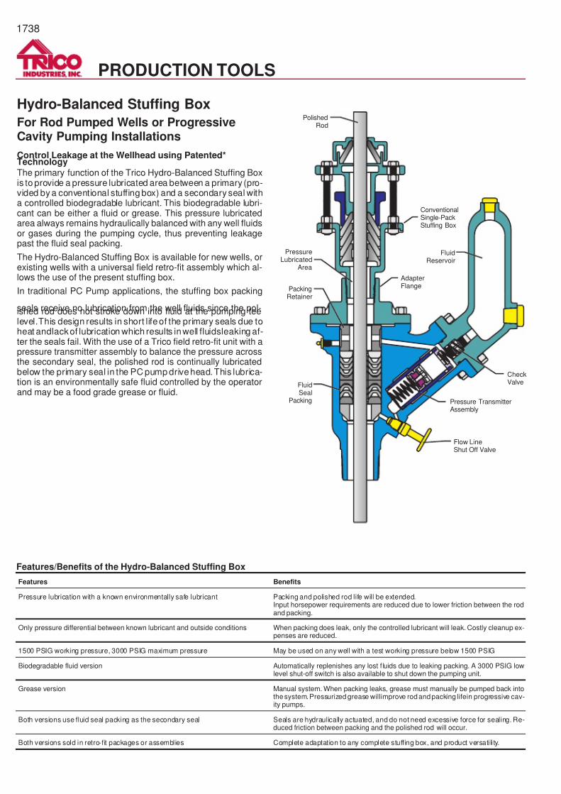
7/14/2019 Equipos Trico
http://slidepdf.com/reader/full/equipos-trico 38/44
1738
PRODUCTION TOOLS
Hydro-Balanced Stuffing Box
For Rod Pumped Wells or ProgressiveCavity Pumping Installations
Control Leakage at the Wellhead using Patented*Technology
The primary function of the Trico Hydro-Balanced Stuffing Boxis to provide a pressure lubricated area between a primary (pro-vided by a conventional stuffing box) and a secondary seal witha controlled biodegradable lubricant. This biodegradable lubri-cant can be either a fluid or grease. This pressure lubricatedarea always remains hydraulically balanced with any well fluidsor gases during the pumping cycle, thus preventing leakagepast the fluid seal packing.
The Hydro-Balanced Stuffing Box is available for new wells, orexisting wells with a universal field retro-fit assembly which al-lows the use of the present stuffing box.
In traditional PC Pump applications, the stuffing box packing
seals receive no lubrication from the well fluids since the pol-ished rod does not stroke down into fluid at the pumping teelevel.This design results in short lifeof the primary seals due toheat andlackof lubrication which results inwell fluidsleaking af-ter the seals fail. With the use of a Trico field retro-fit unit with apressure transmitter assembly to balance the pressure acrossthe secondary seal, the polished rod is continually lubricatedbelow the primary seal in the PC pump drivehead. This lubrica-tion is an environmentally safe fluid controlled by the operatorand may be a food grade grease or fluid.
FluidReservoir
ConventionalSingle-PackStuffing Box
AdapterFlange
CheckValve
Pressure TransmitterAssembly
Flow LineShut Off Valve
PackingRetainer
PolishedRod
PressureLubricated
Area
FluidSeal
Packing
Features/Benefits of the Hydro-Balanced Stuffing Box
Features Benefits
Pressure lubrication with a known environmentally safe lubricant Packing and polished rod life will be extended.Input horsepower requirements are reduced due to lower friction between the rodand packing.
Only pressure differential between known lubricant and outside conditions When packing does leak, only the controlled lubricant will leak. Costly cleanup ex-penses are reduced.
1500 PSIG working pressure, 3000 PSIG maximum pressure May be used on any well with a test working pressure below 1500 PSIG
Biodegradable fluid version Automatically replenishes any lost f luids due to leaking packing. A 3000 PSIG lowlevel shut-off switch is also available to shut down the pumping unit.
Grease version Manual system. When packing leaks, grease must manually be pumped back intothesystem.Pressurized grease willimprove rodandpacking lifein progressive cav-ity pumps.
Both versions use fluid seal packing as the secondary seal Seals are hydraulically actuated, and do not need excessive force for sealing. Re-duced friction between packing and the polished rod will occur.
Both versions sold in retro-fit packages or assemblies Complete adaptation to any complete stuffing box, and product versatility.
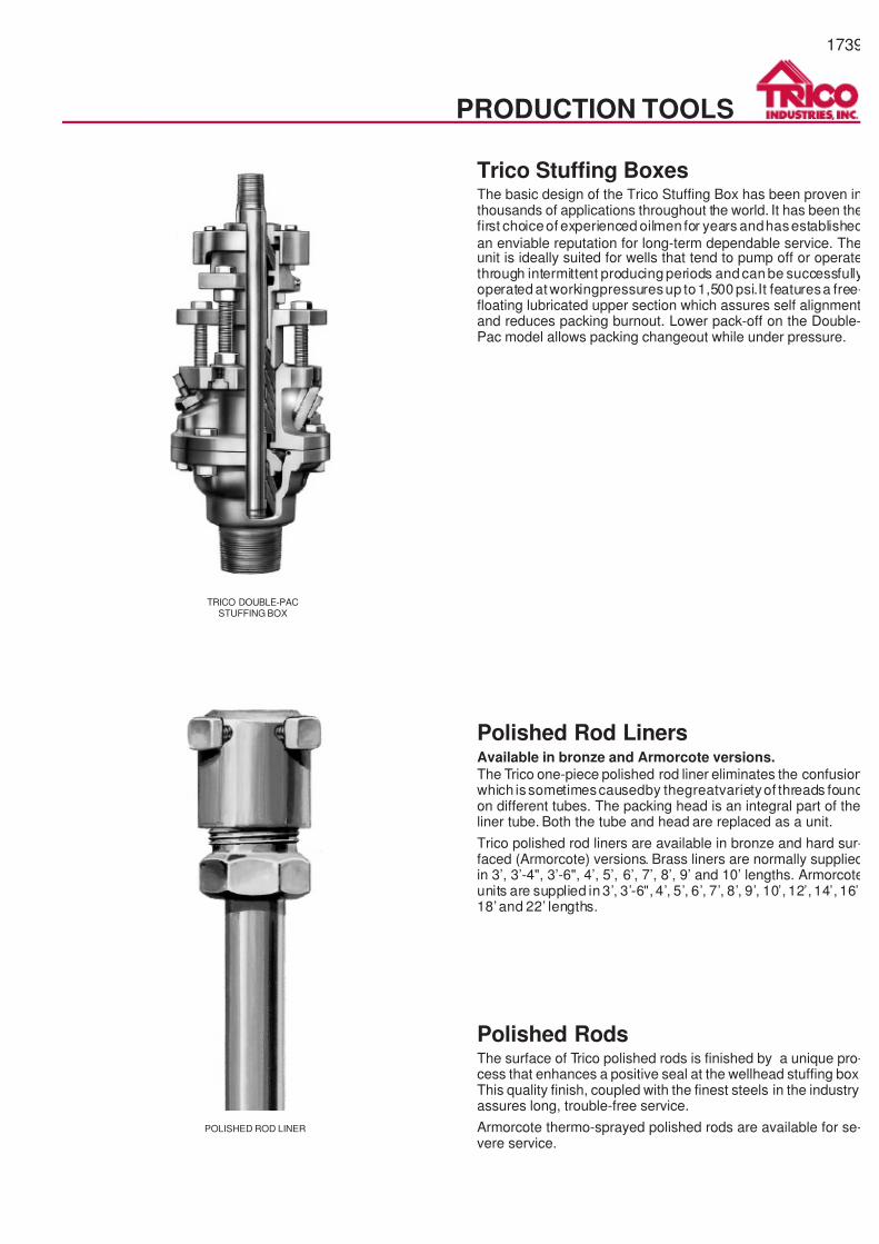
7/14/2019 Equipos Trico
http://slidepdf.com/reader/full/equipos-trico 39/44
1739
PRODUCTION TOOLS
TRICO DOUBLE-PACSTUFFING BOX
Trico Stuffing BoxesThe basic design of the Trico Stuffing Box has been proven inthousands of applications throughout the world. It has been thefirst choiceof experienced oilmen for years andhasestablished
an enviable reputation for long-term dependable service. Theunit is ideally suited for wells that tend to pump off or operatethrough intermittent producing periods and can be successfullyoperated at workingpressuresup to1,500 psi.It featuresa free-floating lubricated upper section which assures self alignmentand reduces packing burnout. Lower pack-off on the Double-Pac model allows packing changeout while under pressure.
POLISHED ROD LINER
Polished Rod LinersAvailable in bronze and Armorcote versions.
The Trico one-piece polished rod liner eliminates the confusionwhich issometimescausedby thegreatvarietyof threads foundon different tubes. The packing head is an integral part of theliner tube. Both the tube and head are replaced as a unit.
Trico polished rod liners are available in bronze and hard sur-faced (Armorcote) versions. Brass liners are normally suppliedin 3’, 3’-4", 3’-6", 4’, 5’, 6’, 7’, 8’, 9’ and 10’ lengths. Armorcoteunits are supplied in 3’, 3’-6", 4’, 5’, 6’, 7’, 8’, 9’, 10’, 12’, 14’, 16’,18’ and 22’ lengths.
Polished RodsThe surface of Trico polished rods is finished by a unique pro-cess that enhances a positive seal at the wellhead stuffing box.This quality finish, coupled with the finest steels in the industry,assures long, trouble-free service.
Armorcote thermo-sprayed polished rods are available for se-vere service.
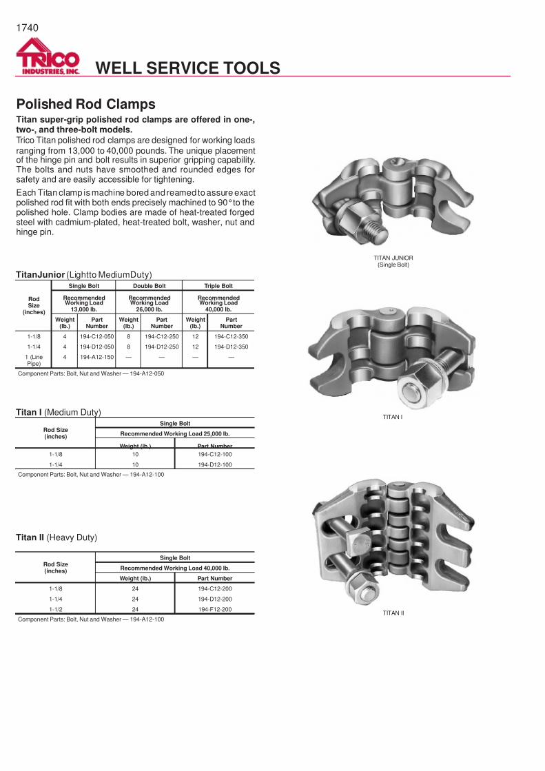
7/14/2019 Equipos Trico
http://slidepdf.com/reader/full/equipos-trico 40/44
1740
WELL SERVICE TOOLS
TITAN JUNIOR(Single Bolt)
TITAN I
TITAN II
Polished Rod ClampsTitan super-grip polished rod clamps are offered in one-,two-, and three-bolt models.
Trico Titan polished rod clamps are designed for working loads
ranging from 13,000 to 40,000 pounds. The unique placementof the hinge pin and bolt results in superior gripping capability.The bolts and nuts have smoothed and rounded edges forsafety and are easily accessible for tightening.
Each Titan clamp is machine bored andreamedtoassure exactpolished rod fit with both ends precisely machined to 90°to thepolished hole. Clamp bodies are made of heat-treated forgedsteel with cadmium-plated, heat-treated bolt, washer, nut andhinge pin.
RodSize
(inches)
Single Bolt Double Bolt Triple Bolt
RecommendedWorking Load
13,000 lb.
RecommendedWorking Load
26,000 lb.
RecommendedWorking Load
40,000 lb.
Weight(lb.)
PartNumber
Weight(lb.)
PartNumber
Weight(lb.)
PartNumber
1-1/8 4 194-C12-050 8 194-C12-250 12 194-C12-350
1-1/4 4 194-D12-050 8 194-D12-250 12 194-D12-350
1 (LinePipe)
4 194-A12-150 — — — —
Component Parts: Bolt, Nut and Washer — 194-A12-050
Rod Size(inches)
Single Bolt
Recommended Working Load 25,000 lb.
Weight (lb.) Part Number
1-1/8 10 194-C12-100
1-1/4 10 194-D12-100
Component Parts: Bolt, Nut and Washer — 194-A12-100
Rod Size(inches)
Single Bolt
Recommended Working Load 40,000 lb.
Weight (lb.) Part Number
1-1/8 24 194-C12-200
1-1/4 24 194-D12-200
1-1/2 24 194-F12-200
Component Parts: Bolt, Nut and Washer — 194-A12-100
TitanJunior (Lightto MediumDuty)
Titan I (Medium Duty)
Titan II (Heavy Duty)
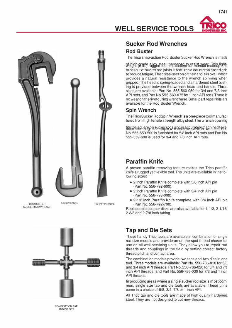
7/14/2019 Equipos Trico
http://slidepdf.com/reader/full/equipos-trico 41/44
1741
WELL SERVICE TOOLS
ROD BUSTERSUCKER ROD WRENCH
PARAFFIN KNIFESPIN WRENCH
COMBINATION TAPAND DIE SET
Sucker Rod Wrenches
Rod BusterThe Trico snap-action Rod Buster Sucker Rod Wrench is made
of high-grade alloy steel, hardened to resist wear. This light-weight (6 lb.) rugged tool is excellent for manual makeup andbreakout of sucker rod joints. It features a counterbalanced gripto reduce fatigue. Thecross-section of thehandle is oval, whichprovides a natural resistance to the wrench spinning whengripped. The head is spring-loaded and a hardened steel bush-ing is provided between the wrench head and handle. Threesizes are available: Part No. 555-560-050 for 3/4 and 7/8 inchAPI rods, and Part No.555-560-075 for 1 inch API rods.There isnowear on therivetduring wrenchuse.Smallpart repairkits areavailable for the Rod Buster Wrench.
Spin WrenchTheTricoSucker RodSpin Wrench isa one-piece tool manufac-tured from high tensile strength alloy steel.The wrench opening
fits the square on sucker rods and is accurately machined to re-duce user fatigue.Thespin wrench is available in twosizes: PartNo.555-559-500 is furnished for 5/8 inch API rods and Part No555-559-600 is used for 3/4 and 7/8 inch API rods.
Paraffin KnifeA proven paraffin-removing feature makes the Trico paraffinknife a rugged yet flexible tool. The units are available in the fol-lowing sizes:
·
2 inch Paraffin Knife complete with 5/8 inch API pin(Part No. 556-792-600).
·
2 inch Paraffin Knife complete with 3/4 inch API pin(Part No. 556-793-000).
·
2-1/2 inch Paraffin Knife complete with 3/4 inch API pin(Part No. 556-792-700).
Replaceable scraper disks are also available for 1-1/2, 2-1/16,2-3/8 and 2-7/8 inch tubing.
Tap and Die SetsThese handy Trico tools are available in combination or singlerod size models and provide an on-the-spot thread chaser foruse on all well servicing units. They allow you to repair rodthreads and couplings in the field by setting correct factorythread pitch and contact area.
The combination models provide two taps and two dies in onetool. Three models are available: Part No. 556-786-010 for 5/8and 3/4 inch API threads, Part No.556-786-020 for 3/4 and 7/8inch API threads, and Part No. 556-786-030 for 7/8 and 1 inchAPI threads.
In producing areas where a single sucker rod size is most com-mon, single size tap and die tools are available. These unitscome in a choice of 5/8, 3/4, 7/8 or 1 inch API.
All Trico tap and die tools are made of high quality hardenedsteel. They are not designed to cut new threads.
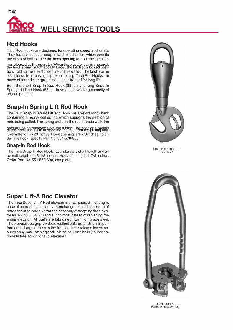
7/14/2019 Equipos Trico
http://slidepdf.com/reader/full/equipos-trico 42/44
1742
WELL SERVICE TOOLS
SNAP-IN SPRING LIFTROD HOOK
SUPER LIFT-APLATE TYPE ELEVATOR
Super Lift-A Rod ElevatorTheTrico Super Lift-ARod Elevator is unsurpassed in strength,ease of operation and safety. Interchangeable rod plates are ofhardenedsteel andgiveyouthe economy of adapting theeleva-tor for 1/2, 5/8, 3/4, 7/8 and 1 inch rods instead of replacing theentire elevator. All parts are fabricated from high grade steel.Theelevatordesignprovides excellent balance andnon-tilt per-formance. Large access to the front and rear release levers as-sures easy, safe latching and unlatching.Long bails (19 inches)provide free action for sub elevators.
Rod HooksTrico Rod Hooks are designed for operating speed and safety.They feature a special snap-in latch mechanism which permitsthe elevator bail to enter the hook opening without the latch be-
ingreleased by theoperator. When theelevatorbail is engaged,the hook spring automatically forces the latch to a locked posi-tion, holding theelevatorsecure until released.The latch springis enclosed in a housing to prevent fouling.Trico Rod Hooks aremade of forged high-grade steel, heat treated for long life.
Both the short Snap-In Rod Hook (33 lb.) and long Snap-InSpring Lift Rod Hook (55 lb.) have a safe working capacity of35,000 pounds.
Snap-In Spring Lift Rod HookThe Trico Snap-In Spring LiftRod Hook has anextra long shankcontaining a heavy coil spring which supports the section ofrods being pulled.The spring protects the rod threads while the
rods are being removed from the tubing. The additional weightof this hook assists in unspooling the line from the pulling unit.Overall length is 23 inches. Hook opening is 1-7/8 inches. To or-der this hook, specify Part No. 554-578-800.
Snap-In Rod HookThe Trico Snap-In Rod Hook has a standardshaft lengthand anoverall length of 18-1/2 inches. Hook opening is 1-7/8 inches.Order Part No. 554-578-600, complete.
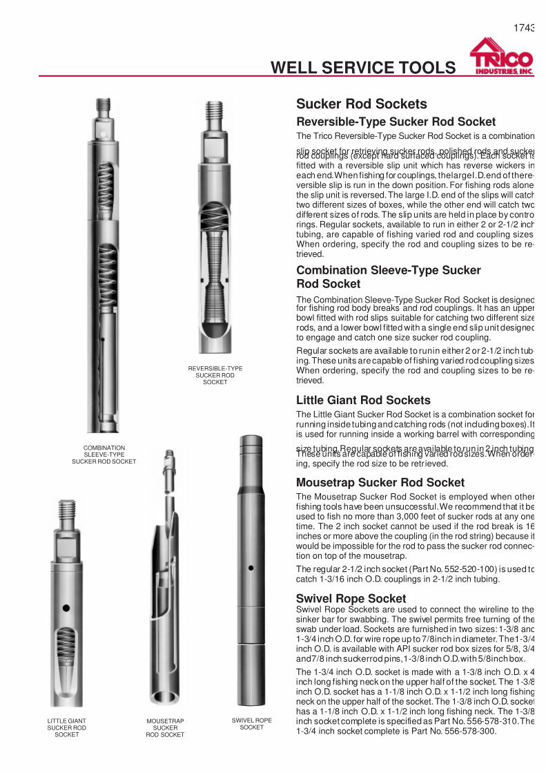
7/14/2019 Equipos Trico
http://slidepdf.com/reader/full/equipos-trico 43/44
1743
Little Giant Rod SocketsThe Little Giant Sucker Rod Socket is a combination socket forrunning inside tubingand catching rods (not includingboxes).Itis used for running inside a working barrel with corresponding
size tubing.Regular sockets areavailable to run in 2 inch tubing.These units arecapable of fishing varied rodsizes.When order-ing, specify the rod size to be retr ieved.
Mousetrap Sucker Rod SocketThe Mousetrap Sucker Rod Socket is employed when otherfishing tools have been unsuccessful.We recommend that it beused to fish no more than 3,000 feet of sucker rods at any onetime. The 2 inch socket cannot be used if the rod break is 16inches or more above the coupling (in the rod string) because itwould be impossible for the rod to pass the sucker rod connec-tion on top of the mousetrap.
The regular 2-1/2 inch socket (Part No. 552-520-100) is used tocatch 1-3/16 inch O.D. couplings in 2-1/2 inch tubing.
Swivel Rope SocketSwivel Rope Sockets are used to connect the wireline to thesinker bar for swabbing. The swivel permits free turning of theswab under load. Sockets are furnished in two sizes:1-3/8 and1-3/4 inch O.D. for wire rope up to7/8inch in diameter.The1-3/4inch O.D. is available with API sucker rod box sizes for 5/8, 3/4and7/8 inch suckerrod pins,1-3/8 inch O.D.with5/8inchbox.
The 1-3/4 inch O.D. socket is made with a 1-3/8 inch O.D. x 4inch long fishing neck on the upper half of the socket. The 1-3/8inch O.D. socket has a 1-1/8 inch O.D. x 1-1/2 inch long fishingneck on the upper half of the socket.The 1-3/8 inch O.D. sockethas a 1-1/8 inch O.D. x 1-1/2 inch long fishing neck. The 1-3/8inch socket complete is specified as Part No. 556-578-310.The1-3/4 inch socket complete is Part No. 556-578-300.
WELL SERVICE TOOLS
LITTLE GIANTSUCKER ROD
SOCKET
SWIVEL ROPESOCKET
MOUSETRAPSUCKER
ROD SOCKET
COMBINATIONSLEEVE-TYPE
SUCKER ROD SOCKET
REVERSIBLE-TYPESUCKER ROD
SOCKET
Sucker Rod Sockets
Reversible-Type Sucker Rod SocketThe Trico Reversible-Type Sucker Rod Socket is a combination
slip socket for retrieving sucker rods, polished rods and suckerrod couplings (except hard surfaced couplings).Each socket isfitted with a reversible slip unit which has reverse wickers ineach end.When fishing for couplings, thelargeI.D.end of there-versible slip is run in the down position. For fishing rods alonethe slip unit is reversed.The large I.D. end of the slips will catchtwo different sizes of boxes, while the other end will catch twodifferent sizes of rods. The slip units are held in place by controlrings. Regular sockets, available to run in either 2 or 2-1/2 inchtubing, are capable of fishing varied rod and coupling sizes.When ordering, specify the rod and coupling sizes to be re-trieved.
Combination Sleeve-Type SuckerRod Socket
The Combination Sleeve-Type Sucker Rod Socket is designedfor fishing rod body breaks and rod couplings. It has an upperbowl fitted with rod slips suitable for catching two different sizerods, and a lower bowl fitted with a single end slip unit designedto engage and catch one size sucker rod coupling.
Regular sockets are available to runin either 2 or 2-1/2 inch tub-ing. These units arecapable of fishing varied rodcoupling sizesWhen ordering, specify the rod and coupling sizes to be re-trieved.

7/14/2019 Equipos Trico
http://slidepdf.com/reader/full/equipos-trico 44/44
SALES & SERVICE LOCATIONS
ALABAMACitronelle......................(334) 866-5055
FAX.........................(334) 866-5534
ALASKAAnchorage....................(907) 248-1005
FAX.........................(907) 243-4350
ARKANSASSmackover ............... ....(501) 725-2085
FAX.........................(501) 725-2086
CALIFORNIABakersfield ............... ....(805) 397-9692
FAX.........................(805) 397-9527Bakersfield ............... ....(805) 397-9085
FAX.........................(805) 397-9405Long Beach†................(562) 595-0931
FAX.........................(562) 988-1035
COLORADODenver .........................(303) 534-5920
FAX.........................(303) 534-6045
ILLINOISGrayville.............. .........(618) 375-6611
FAX.........................(618) 375-7212Robinson......................(618) 544-3154
FAX.........................(618) 544-8090
LOUISIANALafayette ......................(318) 232-4250
FAX.........................(318) 837-6568Vidalia .............. ............(318) 336-7533
FAX.........................(318) 336-8023
MISSISSIPPILaurel ............... ............(601) 649-4467
FAX.........................(601) 428-5522
MONTANAMedicine Lake..............(406) 789-2237
FAX.........................(406) 789-2288Sidney.............. ............(406) 482-2537
FAX.........................(406) 482-2624
NEW MEXICOArtesia..........................(505) 746-2784
FAX.........................(505) 746-2916Farmington...................(505) 564-8381
FAX.........................(505) 564-8194Hobbs...........................(505) 393-2522
FAX.........................(505) 393-5120
NORTH DAKOTADickinson .....................(701) 227-8768
FAX.........................(701) 227-8769Tioga............................(701) 664-2461
FAX.........................(701) 664-2909Watford City .................(701) 842-4611
FAX.........................(701) 842-6136
OKLAHOMABroken Arrow ...............(918) 258-7607
FAX.........................(918) 251-2608Healdton.......................(405) 229-1229
FAX.........................(405) 229-1235Hennessey... ............... .(405) 853-7127
FAX.........................(405) 853-7129Lindsay.........................(405) 756-4342
FAX.........................(405) 756-3044Oklahoma City .............(405) 672-0228
FAX.........................(405) 677-5091
TEXASAlice ................ .............(512) 664-5301
FAX.........................(512) 664-5302Andrews................. ......(915) 523-5050
FAX.........................(915) 523-5051
Big Spring ....................(915) 267-7172FAX.........................(915) 267-3191
Giddings.......................(409) 542-5154FAX.........................(409) 542-6202
Houston†**...................(281) 405-2800FAX.........................(281) [email protected]
Houston........................(713) 923-6603FAX.........................(713) 923-5238
Kilgore..........................(903) 984-6881FAX.........................(903) 984-6895
Luling ...........................(830) 875-2435FAX.........................(830) 875-9436
Midland† ......................(915) 684-7481FAX.........................(915) 686-9908
Odessa.........................(915) 332-8206FAX.........................(915) 332-7204
Odessa.........................(915) 580-4964FAX.........................(915) 335-9143
Sundown................ ......(806) 229-5131FAX.........................(806) 229-6434
Wichita Falls.................(940) 767-2081FAX.........................(940) 761-3274
UTAHRoosevelt ............... ......(801) 722-4092
FAX.........................(801) 722-2087
WYOMINGCasper .........................(307) 265-2940
FAX.........................(307) 472-0623Gillette..........................(307) 682-8056
FAX.........................(307) 682-1513Powell...........................(307) 754-5613
FAX.........................(307) 754-5709
JAKARTA†62-21-570-1488
FAX........................62-21-578-2330
ECUADOR†593-2-502-244
UNITED KINGDOM†44-1224-735331
FAX..... ............... ...44-1224-735206
† Region Office** International Sales
MANUFACTURING AND MAJOR WAREHOUSE LOCATIONS
2503 Hunter Road, San Marcos, TX 78666
(512) 353-4200q
FAX (512) 353-6213
3218 Kermit Highway, Odessa, TX 79764(915) 580-8661 q FAX (915) 332-0303
6325 Trico Lane, PO Box 1050, Greenville, TX 75403
(903) 455-4441q
FAX: (903) 455-4952
CORPORATE OFFICES
2503 Hunter Road, San Marcos, Texas 78666 Telephone: (512) 353-4200 q FAX (512) 353-6213E-Mail: [email protected]


![PDF Apostila de Trico[1]](https://img.pdfslide.net/doc/110x75/55cf9c59550346d033a98a8c/pdf-apostila-de-trico1.jpg)