Embed Size (px)
Citation preview
Introduction
Although closely related to grounding, bonding is a distinctdiscipline that is essential to the overall facility electricalprotection scheme. Grounding provides the actual physicalconnection to earth used for establishing and maintaining itspotential, theoretically 0 volts. Bonding is the practice ofestablishing an equipotential plane by permanently joiningtogether metal parts of the wiring system as well as tyingtogether all of the electrical service grounds. Proper bonding
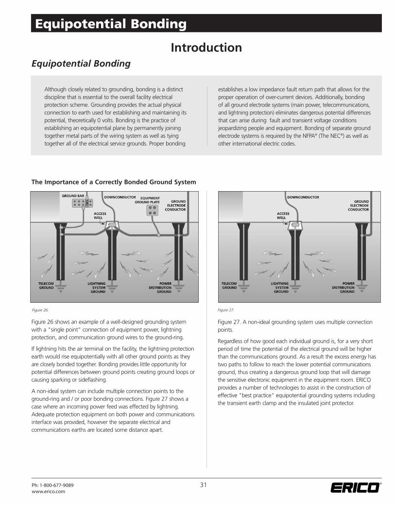
Figure 26 shows an example of a well-designed grounding systemwith a "single point" connection of equipment power, lightningprotection, and communication ground wires to the ground-ring.
If lightning hits the air terminal on the facility, the lightning protectionearth would rise equipotentially with all other ground points as theyare closely bonded together. Bonding provides little opportunity forpotential differences between ground points creating ground loops orcausing sparking or sideflashing.
A non-ideal system can include multiple connection points to theground-ring and / or poor bonding connections. Figure 27 shows acase where an incoming power feed was effected by lightning.Adequate protection equipment on both power and communicationsinterface was provided, however the separate electrical andcommunications earths are located some distance apart.
Figure 27. A non-ideal grounding system uses multiple connectionpoints.
Regardless of how good each individual ground is, for a very shortperiod of time the potential of the electrical ground will be higherthan the communications ground. As a result the excess energy hastwo paths to follow to reach the lower potential communicationsground, thus creating a dangerous ground loop that will damagethe sensitive electronic equipment in the equipment room. ERICOprovides a number of technologies to assist in the construction ofeffective "best practice" equipotential grounding systems includingthe transient earth clamp and the insulated joint protector.
Equipotential Bonding
The Importance of a Correctly Bonded Ground System
establishes a low impedance fault return path that allows for theproper operation of over-current devices. Additionally, bondingof all ground electrode systems (main power, telecommunications,and lightning protection) eliminates dangerous potential differencesthat can arise during fault and transient voltage conditionsjeopardizing people and equipment. Bonding of separate groundelectrode systems is required by the NFPA® (The NEC®) as well asother international electric codes.
Figure 26. Figure 27.
31Ph: 1-800-677-9089www.erico.com
Equipotential Bonding
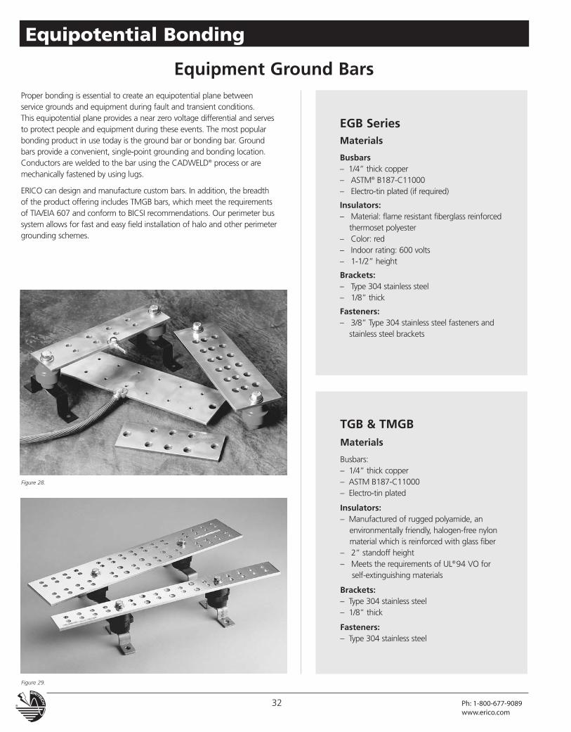
Equipment Ground BarsProper bonding is essential to create an equipotential plane betweenservice grounds and equipment during fault and transient conditions.This equipotential plane provides a near zero voltage differential and servesto protect people and equipment during these events. The most popularbonding product in use today is the ground bar or bonding bar. Groundbars provide a convenient, single-point grounding and bonding location.Conductors are welded to the bar using the CADWELD® process or aremechanically fastened by using lugs.
ERICO can design and manufacture custom bars. In addition, the breadthof the product offering includes TMGB bars, which meet the requirementsof TIA/EIA 607 and conform to BICSI recommendations. Our perimeter bussystem allows for fast and easy field installation of halo and other perimetergrounding schemes.
EGB SeriesMaterials
Busbars– 1/4” thick copper– ASTM® B187-C11000– Electro-tin plated (if required)
Insulators:– Material: flame resistant fiberglass reinforced
thermoset polyester– Color: red– Indoor rating: 600 volts– 1-1/2” height
Brackets:– Type 304 stainless steel– 1/8” thick
Fasteners:– 3/8” Type 304 stainless steel fasteners and
stainless steel brackets
TGB & TMGBMaterials
Busbars:– 1/4” thick copper– ASTM B187-C11000– Electro-tin plated
Insulators:– Manufactured of rugged polyamide, an
environmentally friendly, halogen-free nylonmaterial which is reinforced with glass fiber
– 2” standoff height– Meets the requirements of UL®94 VO for
self-extinguishing materials
Brackets:– Type 304 stainless steel– 1/8” thick
Fasteners:– Type 304 stainless steel
Figure 28.
Figure 29.
32 Ph: 1-800-677-9089www.erico.com
Equipotential Bonding
Equipment Ground Bars
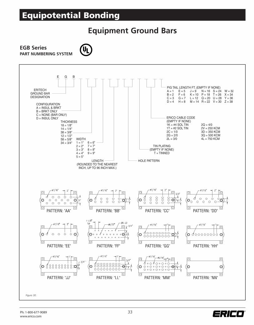
EGB SeriesPART NUMBERING SYSTEM
Figure 30.
33Ph: 1-800-677-9089www.erico.com
Equipotential Bonding
Equipment Ground Bars
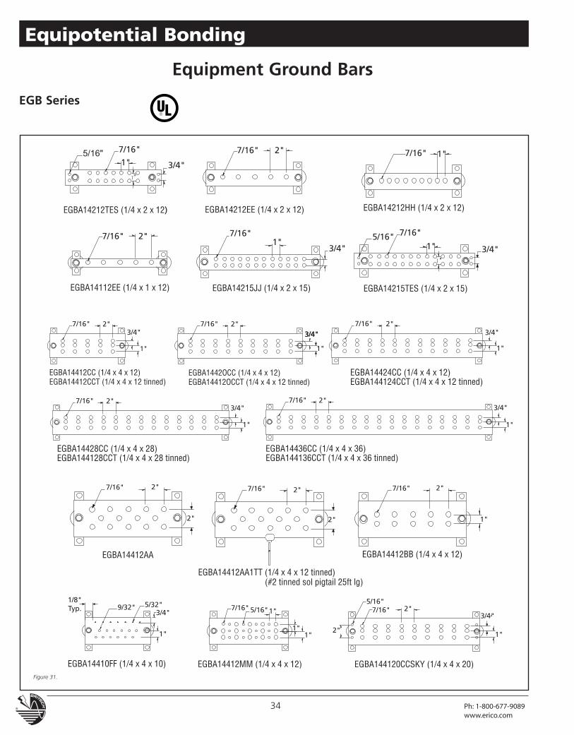
EGB Series
Figure 31.
34 Ph: 1-800-677-9089www.erico.com
Equipotential Bonding
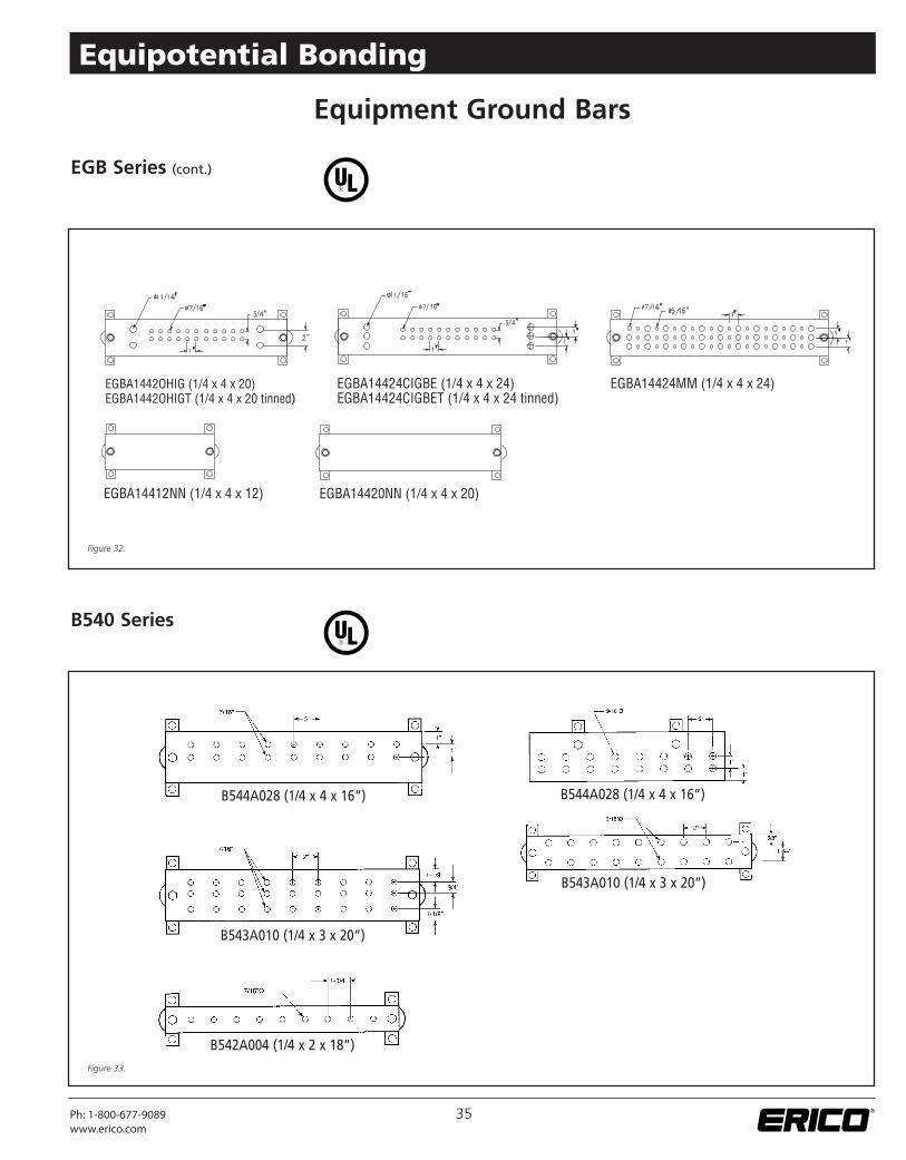
EGB Series (cont.)
B540 Series
B544A028 (1/4 x 4 x 16”)
B543A010 (1/4 x 3 x 20”)
B542A004 (1/4 x 2 x 18”)
B544A028 (1/4 x 4 x 16”)
B543A010 (1/4 x 3 x 20”)
Equipment Ground Bars
Figure 32.
Figure 33.
35Ph: 1-800-677-9089www.erico.com
Equipotential Bonding
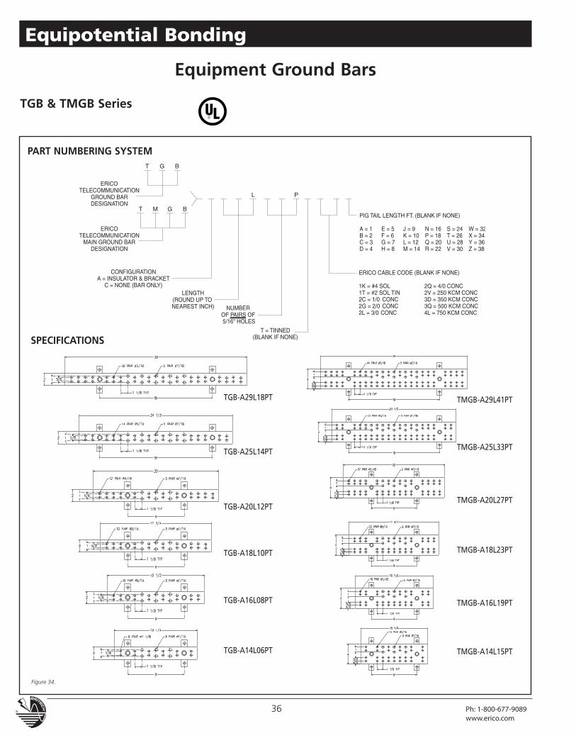
TGB & TMGB Series
Equipment Ground Bars
PART NUMBERING SYSTEM
SPECIFICATIONS
TGB-A29L18PT
TGB-A25L14PT
TGB-A20L12PT
TGB-A18L10PT
TGB-A16L08PT
TGB-A14L06PT
TMGB-A29L41PT
TMGB-A25L33PT
TMGB-A20L27PT
TMGB-A18L23PT
TMGB-A16L19PT
TMGB-A14L15PT
Figure 34.
36 Ph: 1-800-677-9089www.erico.com
Equipotential Bonding
Equipment Ground Bars
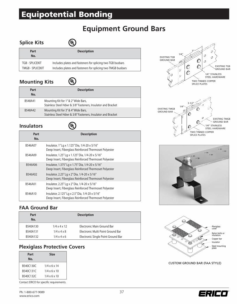
B548A41 Mounting Kit for 1”& 2”Wide Bars,Stainless Steel Hdwr & 3/8” Fasteners, Insulator and Bracket
B548A42 Mounting Kit for 3”& 4”Wide Bars,Stainless Steel Hdwr & 3/8” Fasteners, Insulator and Bracket
Mounting Kits
B546A07 Insulator, 1” Lg x 1.125”Dia, 1/4-20 x 5/16”Deep Insert, Fiberglass Reinforced Thermoset Polyester
B546A09 Insulator, 1.25” Lg x 1.125”Dia, 1/4-20 x 5/16”Deep Insert, Fiberglass Reinforced Thermoset Polyester
B546A06 Insulator, 1.375” Lg x 1.75”Dia, 1/4-20 x 5/16”Deep Insert, Fiberglass Reinforced Thermoset Polyester
B546A02 Insulator, 2.25” Lg x 2”Dia, 1/4-20 x 5/16”Deep Insert, Fiberglass Reinforced Thermoset Polyester
B546A01 Insulator, 2.25” Lg x 2”Dia, 1/4-20 x 5/16”Deep Insert, Fiberglass Reinforced Thermoset Polyester
B546A10 Insulator, 2.125” Lg x 2.5”Dia, 1/4-20 x 5/16”Deep Insert, Fiberglass Reinforced Thermoset Polyester
Insulators
TGB - SPLICEKIT Includes plates and fasteners for splicing two TGB busbars
TMGB - SPLICEKIT Includes plates and fasteners for splicing two TMGB busbars
Part DescriptionNo.
Splice Kits
B540A130 1/4 x 4 x 12 Electronic Main Ground Bar
B540A131 1/4 x 4 x 8 Electronic Multi Point Ground Bar
B540A132 1/4 x 4 x 6 Electronic Single Point Ground Bar
Part DescriptionNo.
FAA Ground Bar
B540C130C 1/4 x 6 x 14
B540C131C 1/4 x 6 x 10
B540C132C 1/4 x 6 x 10
Part SizeNo.
Plexiglass Protective Covers
Part DescriptionNo.
Part DescriptionNo.
1/4”3”
EXISTING TGBGROUND BAR
TWO TINNED COPPERSPLICE PLATES
1/4” STAINLESSSTEEL HARDWARE
EXISTING TGBGROUND BAR
EXISTING TMGBGROUND BAR
EXISTING TMGBGROUND BAR
1/4” STAINLESSSTEEL HARDWARE
TWO TINNED COPPERSPLICE PLATES
1/4”3-1/2”
37Ph: 1-800-677-9089www.erico.com
Equipotential Bonding
Contact ERICO for specific requirements.
®
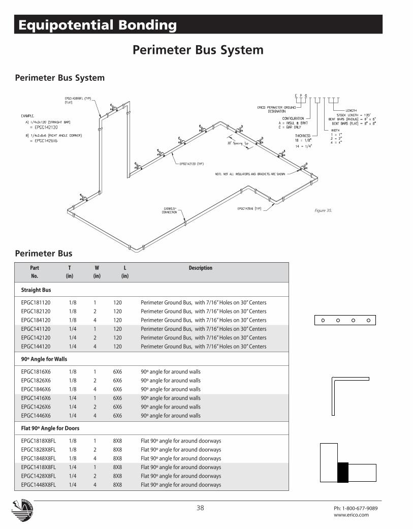
Perimeter Bus System
Straight Bus
EPGC181120 1/8 1 120 Perimeter Ground Bus, with 7/16”Holes on 30”Centers
EPGC182120 1/8 2 120 Perimeter Ground Bus, with 7/16”Holes on 30”Centers
EPGC184120 1/8 4 120 Perimeter Ground Bus, with 7/16”Holes on 30”Centers
EPGC141120 1/4 1 120 Perimeter Ground Bus, with 7/16”Holes on 30”Centers
EPGC142120 1/4 2 120 Perimeter Ground Bus, with 7/16”Holes on 30”Centers
EPGC144120 1/4 4 120 Perimeter Ground Bus, with 7/16”Holes on 30”Centers
90º Angle forWalls
EPGC1816X6 1/8 1 6X6 90º angle for around walls
EPGC1826X6 1/8 2 6X6 90º angle for around walls
EPGC1846X6 1/8 4 6X6 90º angle for around walls
EPGC1416X6 1/4 1 6X6 90º angle for around walls
EPGC1426X6 1/4 2 6X6 90º angle for around walls
EPGC1446X6 1/4 4 6X6 90º angle for around walls
Flat 90º Angle for Doors
EPGC1818X8FL 1/8 1 8X8 Flat 90º angle for around doorways
EPGC1828X8FL 1/8 2 8X8 Flat 90º angle for around doorways
EPGC1848X8FL 1/8 4 8X8 Flat 90º angle for around doorways
EPGC1418X8FL 1/4 1 8X8 Flat 90º angle for around doorways
EPGC1428X8FL 1/4 2 8X8 Flat 90º angle for around doorways
EPGC1448X8FL 1/4 4 8X8 Flat 90º angle for around doorways
Part T W L DescriptionNo. (in) (in) (in)
Perimeter Bus
Perimeter Bus System
Figure 35.
38 Ph: 1-800-677-9089www.erico.com
Equipotential Bonding
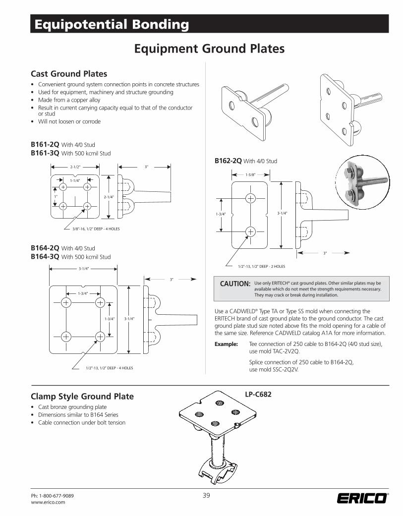
Use only ERITECH® cast ground plates. Other similar plates may beavailable which do not meet the strength requirements necessary.They may crack or break during installation.
CAUTION:
2-1/2"
1-5/8"
3-1/4"
1-3/4"
1-3/4" 3-1/4"
1-3/4" 3-1/4"
2-1/4"
1-1/4"
1"
3"
3"
3"
3/8"-16, 1/2" DEEP - 4 HOLES
1/2"-13, 1/2" DEEP - 2 HOLES
1/2"-13, 1/2" DEEP - 4 HOLES
B161-2Q With 4/0 StudB161-3Q With 500 kcmil Stud
B164-2Q With 4/0 StudB164-3Q With 500 kcmil Stud
B162-2QWith 4/0 Stud
Use a CADWELD® Type TA or Type SS mold when connecting theERITECH brand of cast ground plate to the ground conductor. The castground plate stud size noted above fits the mold opening for a cable ofthe same size. Reference CADWELD catalog A1A for more information.
Example: Tee connection of 250 cable to B164-2Q (4/0 stud size),use mold TAC-2V2Q.
Splice connection of 250 cable to B164-2Q,use mold SSC-2Q2V.
Cast Ground Plates• Convenient ground system connection points in concrete structures• Used for equipment, machinery and structure grounding• Made from a copper alloy• Result in current carrying capacity equal to that of the conductor
or stud• Will not loosen or corrode
Clamp Style Ground Plate• Cast bronze grounding plate• Dimensions similar to B164 Series• Cable connection under bolt tension
LP-C682
Equipment Ground Plates
39Ph: 1-800-677-9089www.erico.com
Equipotential Bonding
Equipment Ground Plates
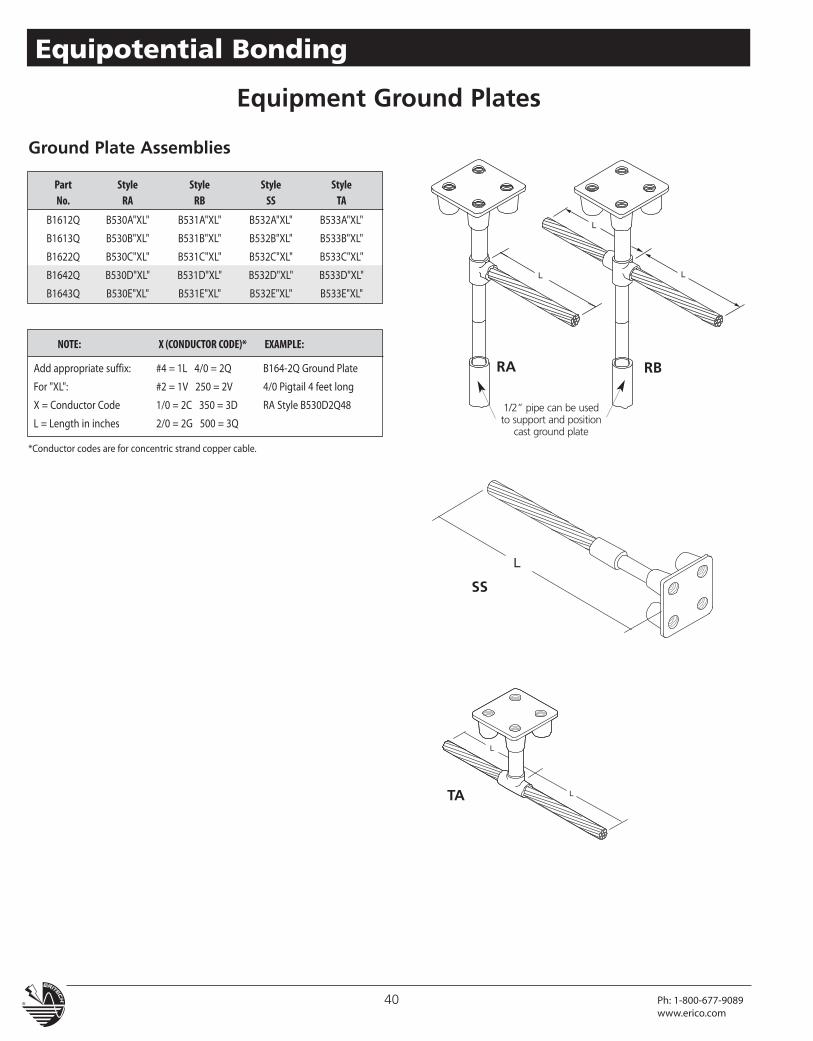
NOTE: X (CONDUCTOR CODE)* EXAMPLE:
Add appropriate suffix: #4 = 1L 4/0 = 2Q B164-2Q Ground Plate
For "XL": #2 = 1V 250 = 2V 4/0 Pigtail 4 feet long
X = Conductor Code 1/0 = 2C 350 = 3D RA Style B530D2Q48
L = Length in inches 2/0 = 2G 500 = 3Q1/2” pipe can be usedto support and position
cast ground plate
RA RB
SS
TA
*Conductor codes are for concentric strand copper cable.
Ground Plate Assemblies
Part Style Style Style StyleNo. RA RB SS TA
B1612Q B530A"XL" B531A"XL" B532A"XL" B533A"XL"
B1613Q B530B"XL" B531B"XL" B532B"XL" B533B"XL"
B1622Q B530C"XL" B531C"XL" B532C"XL" B533C"XL"
B1642Q B530D"XL" B531D"XL" B532D"XL" B533D"XL"
B1643Q B530E"XL" B531E"XL" B532E"XL" B533E"XL"
40 Ph: 1-800-677-9089www.erico.com
Equipotential Bonding
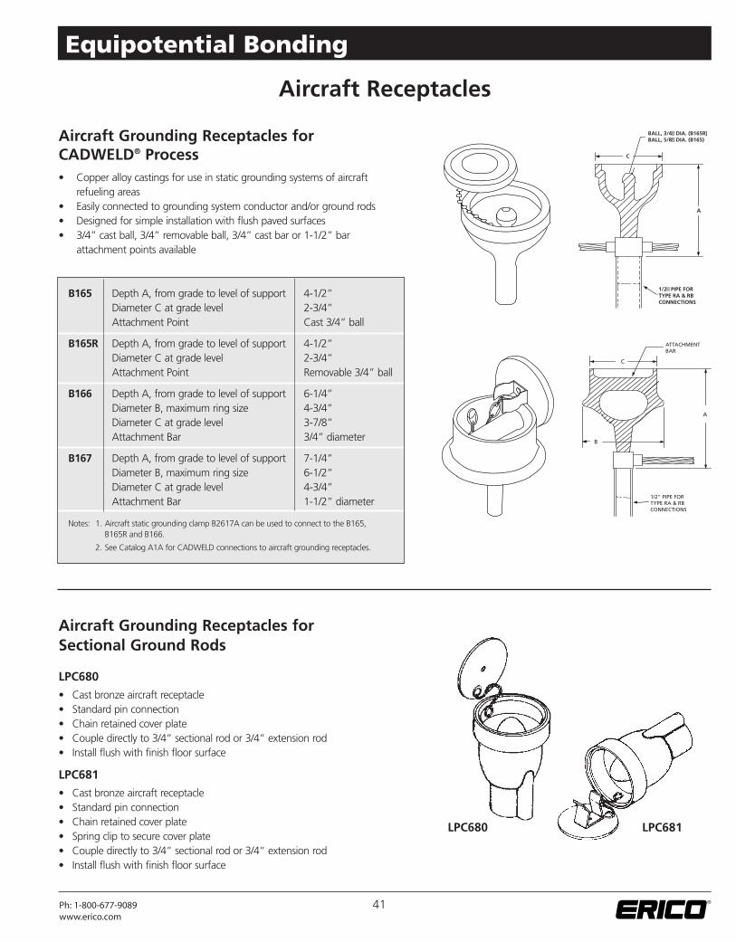
Aircraft Grounding Receptacles forSectional Ground Rods
LPC680
• Cast bronze aircraft receptacle• Standard pin connection• Chain retained cover plate• Couple directly to 3/4” sectional rod or 3/4” extension rod• Install flush with finish floor surface
LPC681
• Cast bronze aircraft receptacle• Standard pin connection• Chain retained cover plate• Spring clip to secure cover plate• Couple directly to 3/4” sectional rod or 3/4” extension rod• Install flush with finish floor surface
Aircraft Receptacles
Aircraft Grounding Receptacles forCADWELD® Process• Copper alloy castings for use in static grounding systems of aircraft
refueling areas• Easily connected to grounding system conductor and/or ground rods• Designed for simple installation with flush paved surfaces• 3/4” cast ball, 3/4” removable ball, 3/4” cast bar or 1-1/2” bar
attachment points available
C
A
BALL, 3/4" DIA. (B165R)BALL, 5/8" DIA. (B165)
1/2" PIPE FORTYPE RA & RBCONNECTIONS
B165 Depth A, from grade to level of support 4-1/2”Diameter C at grade level 2-3/4”Attachment Point Cast 3/4” ball
B165R Depth A, from grade to level of support 4-1/2”Diameter C at grade level 2-3/4”Attachment Point Removable 3/4” ball
B166 Depth A, from grade to level of support 6-1/4”Diameter B, maximum ring size 4-3/4”Diameter C at grade level 3-7/8”Attachment Bar 3/4” diameter
B167 Depth A, from grade to level of support 7-1/4”Diameter B, maximum ring size 6-1/2”Diameter C at grade level 4-3/4”Attachment Bar 1-1/2” diameter
Notes: 1. Aircraft static grounding clamp B2617A can be used to connect to the B165,B165R and B166.
2. See Catalog A1A for CADWELD connections to aircraft grounding receptacles.
LPC680 LPC681
41Ph: 1-800-677-9089www.erico.com
Equipotential Bonding
Transient Earth Clamp/Joint Protector
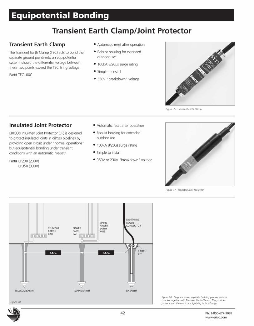
Transient Earth ClampThe Transient Earth Clamp (TEC) acts to bond theseparate ground points into an equipotentialsystem, should the differential voltage betweenthese two points exceed the TEC firing voltage.
Part# TEC100C
Insulated Joint ProtectorERICO’s Insulated Joint Protector (IJP) is designedto protect insulated joints in oil/gas pipelines byproviding open circuit under "normal operations"but equipotential bonding under transientconditions with an automatic "re-set".
Part# IJP230 (230V)IJP350 (330V)
• Automatic reset after operation
• Robust housing for extendedoutdoor use
• 100kA 8/20µs surge rating
• Simple to install
• 350V "breakdown" voltage
• Automatic reset after operation
• Robust housing for extendedoutdoor use
• 100kA 8/20µs surge rating
• Simple to install
• 350V or 230V "breakdown" voltage
Figure 36. Transient Earth Clamp.
Figure 38. Diagram shows separate building ground systemsbonded together with Transient Earth Clamps. This providesprotection in the event of a lightning induced surge.
Figure 37. Insulated Joint Protector
42 Ph: 1-800-677-9089www.erico.com
Equipotential Bonding
Figure 38
Signal Reference Grid (SRG)
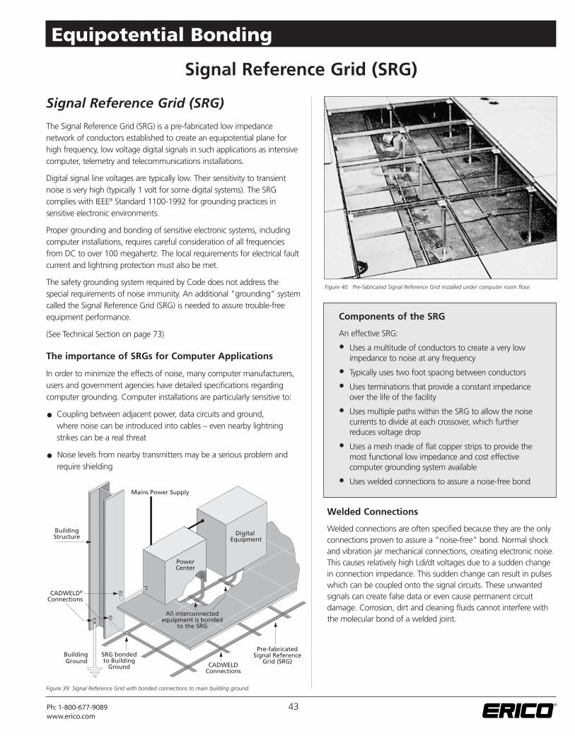
The Signal Reference Grid (SRG) is a pre-fabricated low impedancenetwork of conductors established to create an equipotential plane forhigh frequency, low voltage digital signals in such applications as intensivecomputer, telemetry and telecommunications installations.
Digital signal line voltages are typically low. Their sensitivity to transientnoise is very high (typically 1 volt for some digital systems). The SRGcomplies with IEEE® Standard 1100-1992 for grounding practices insensitive electronic environments.
Proper grounding and bonding of sensitive electronic systems, includingcomputer installations, requires careful consideration of all frequenciesfrom DC to over 100 megahertz. The local requirements for electrical faultcurrent and lightning protection must also be met.
The safety grounding system required by Code does not address thespecial requirements of noise immunity. An additional "grounding" systemcalled the Signal Reference Grid (SRG) is needed to assure trouble-freeequipment performance.
(See Technical Section on page 73)
The importance of SRGs for Computer Applications
In order to minimize the effects of noise, many computer manufacturers,users and government agencies have detailed specifications regardingcomputer grounding. Computer installations are particularly sensitive to:
• Coupling between adjacent power, data circuits and ground,where noise can be introduced into cables – even nearby lightningstrikes can be a real threat
• Noise levels from nearby transmitters may be a serious problem andrequire shielding
Welded Connections
Welded connections are often specified because they are the onlyconnections proven to assure a "noise-free" bond. Normal shockand vibration jar mechanical connections, creating electronic noise.This causes relatively high Ldi/dt voltages due to a sudden changein connection impedance. This sudden change can result in pulseswhich can be coupled onto the signal circuits. These unwantedsignals can create false data or even cause permanent circuitdamage. Corrosion, dirt and cleaning fluids cannot interfere withthe molecular bond of a welded joint.
Signal Reference Grid (SRG)
Components of the SRG
An effective SRG:
• Uses a multitude of conductors to create a very lowimpedance to noise at any frequency
• Typically uses two foot spacing between conductors
• Uses terminations that provide a constant impedanceover the life of the facility
• Uses multiple paths within the SRG to allow the noisecurrents to divide at each crossover, which furtherreduces voltage drop
• Uses a mesh made of flat copper strips to provide themost functional low impedance and cost effectivecomputer grounding system available
• Uses welded connections to assure a noise-free bond
®
Figure 39. Signal Reference Grid with bonded connections to main building ground.
Figure 40. Pre-fabricated Signal Reference Grid installed under computer room floor.
43Ph: 1-800-677-9089www.erico.com
Equipotential Bonding
Installation
Important points to consider when installing an SRG:
• Local codes must be followed.
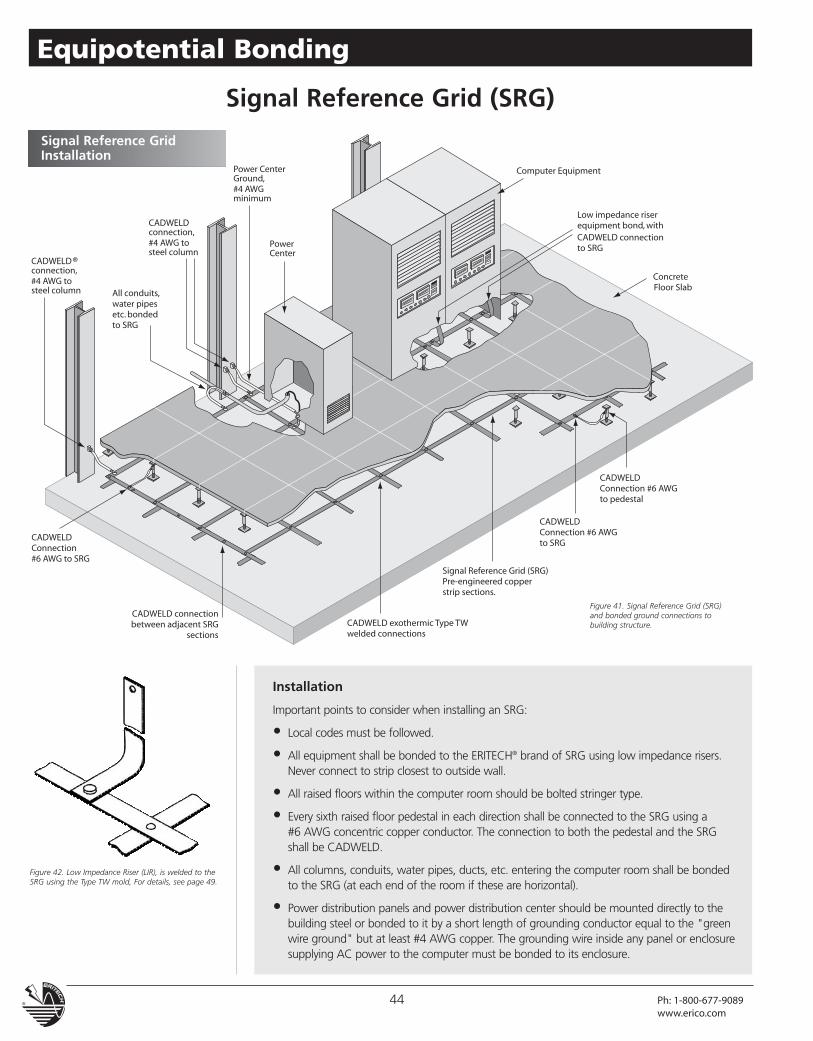
• All equipment shall be bonded to the ERITECH® brand of SRG using low impedance risers.Never connect to strip closest to outside wall.
• All raised floors within the computer room should be bolted stringer type.
• Every sixth raised floor pedestal in each direction shall be connected to the SRG using a#6 AWG concentric copper conductor. The connection to both the pedestal and the SRGshall be CADWELD.
• All columns, conduits, water pipes, ducts, etc. entering the computer room shall be bondedto the SRG (at each end of the room if these are horizontal).
• Power distribution panels and power distribution center should be mounted directly to thebuilding steel or bonded to it by a short length of grounding conductor equal to the "greenwire ground" but at least #4 AWG copper. The grounding wire inside any panel or enclosuresupplying AC power to the computer must be bonded to its enclosure.
Figure 41. Signal Reference Grid (SRG)and bonded ground connections tobuilding structure.
Figure 42. Low Impedance Riser (LIR), is welded to theSRG using the Type TW mold, For details, see page 49.
Signal Reference GridInstallation
Signal Reference Grid (SRG)
44 Ph: 1-800-677-9089www.erico.com
Equipotential Bonding
How to Specify
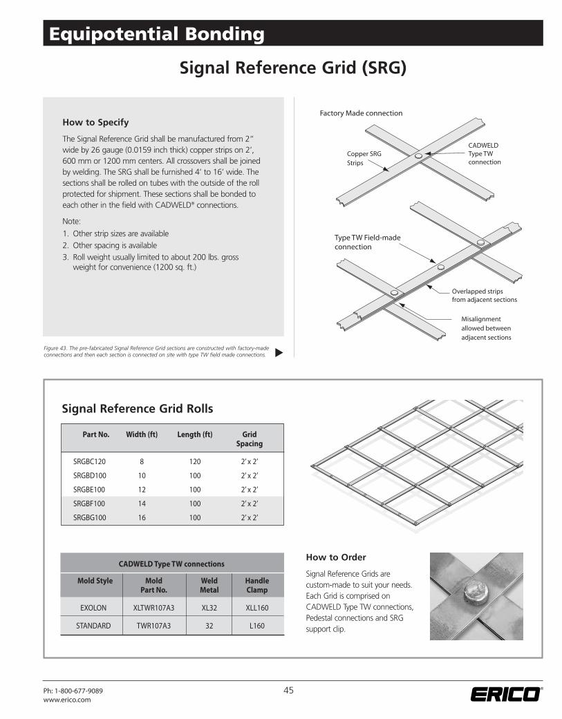
The Signal Reference Grid shall be manufactured from 2”wide by 26 gauge (0.0159 inch thick) copper strips on 2’,600 mm or 1200 mm centers. All crossovers shall be joinedby welding. The SRG shall be furnished 4’ to 16’ wide. Thesections shall be rolled on tubes with the outside of the rollprotected for shipment. These sections shall be bonded toeach other in the field with CADWELD® connections.
Note:
1. Other strip sizes are available2. Other spacing is available3. Roll weight usually limited to about 200 lbs. gross
weight for convenience (1200 sq. ft.)
Figure 43. The pre-fabricated Signal Reference Grid sections are constructed with factory-madeconnections and then each section is connected on site with type TW field made connections.
How to Order
Signal Reference Grids arecustom-made to suit your needs.Each Grid is comprised onCADWELD Type TW connections,Pedestal connections and SRGsupport clip.
CADWELD Type TW connections
Mold Style Mold Weld HandlePart No. Metal Clamp
EXOLON XLTWR107A3 XL32 XLL160
STANDARD TWR107A3 32 L160
�
Signal Reference Grid (SRG)
Part No. Width (ft) Length (ft) GridSpacing
SRGBC120 8 120 2’ x 2’
SRGBD100 10 100 2’ x 2’
SRGBE100 12 100 2’ x 2’
SRGBF100 14 100 2’ x 2’
SRGBG100 16 100 2’ x 2’
Signal Reference Grid Rolls
45Ph: 1-800-677-9089www.erico.com
Equipotential Bonding
SRG Support Clip
When retrofitting an existing computer room, the SRG can besupported above the power and data cables with the ERITECH®
brand of SRG Support Clip.
Part No. B818A01 to fit both 1" round and 7/8" square raisedfloor pedestal.
1” Round
7/8” Square
Signal Reference Grid (SRG)
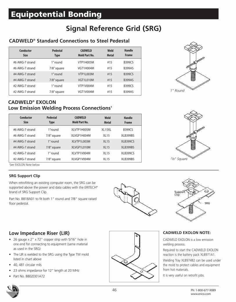
CADWELD® Standard Connections to Steel Pedestal
CADWELD® EXOLONLow Emission Welding Process Connections1
1See EXOLON Note below
#6 AWG-7 strand 1” round VTP1H005M #15 B399CS
#6 AWG-7 strand 7/8” square VGT1H004M #15 B399AS
#4 AWG-7 strand 1” round VTP1L003M #15 B399CS
#4 AWG-7 strand 7/8” square VGT1L010M #15 B399AS
#2 AWG-7 strand 1” round VTP1V004M #15 B399CS
#2 AWG-7 strand 7/8” square VGT1V004M #15 B399AS
Low Impedance Riser (LIR)• 26 gauge x 2” x 72” copper strip with 5/16” hole in
one end for connecting to equipment (same materialas used in the SRG)
• The LIR is welded to the SRG using the Type TW moldlisted in chart above
• 40, 481 circular mils
• 23 ohms impedance for 12” length at 20 MHz
• Part No. B802D01A72
CADWELD EXOLON NOTE:
CADWELD EXOLON is a low emissionwelding process.
Required to start the CADWELD EXOLONreaction is the battery pack XLB971A1.
Welding Tray XLB974B2 can be used underthe mold to protect cables and equipmentfrom hot materials.
It is very useful on retrofit jobs.
46 Ph: 1-800-677-9089www.erico.com
Equipotential Bonding
ConductorSize
PedestalType
CADWELDMold Part No.
WeldMetal
HandleFrame
ConductorSize
PedestalType
CADWELDMold Part No.
WeldMetal
HandleFrame
#6 AWG-7 strand 1”round XLVTP1H005M XL15XL B399CS
#6 AWG-7 strand 7/8” square XLVGP1H004M XL15 XLB399BS
#4 AWG-7 strand 1” round XLVTP1L003M XL15 XLB399CS
#4 AWG-7 strand 7/8” square XLVGP1L010M XL15 XLB399BS
#2 AWG-7 strand 1” round XLVTP1V004M XL15 XLB399CS
#2 AWG-7 strand 7/8” square XLVGP1V004M XL15 XLB399BS
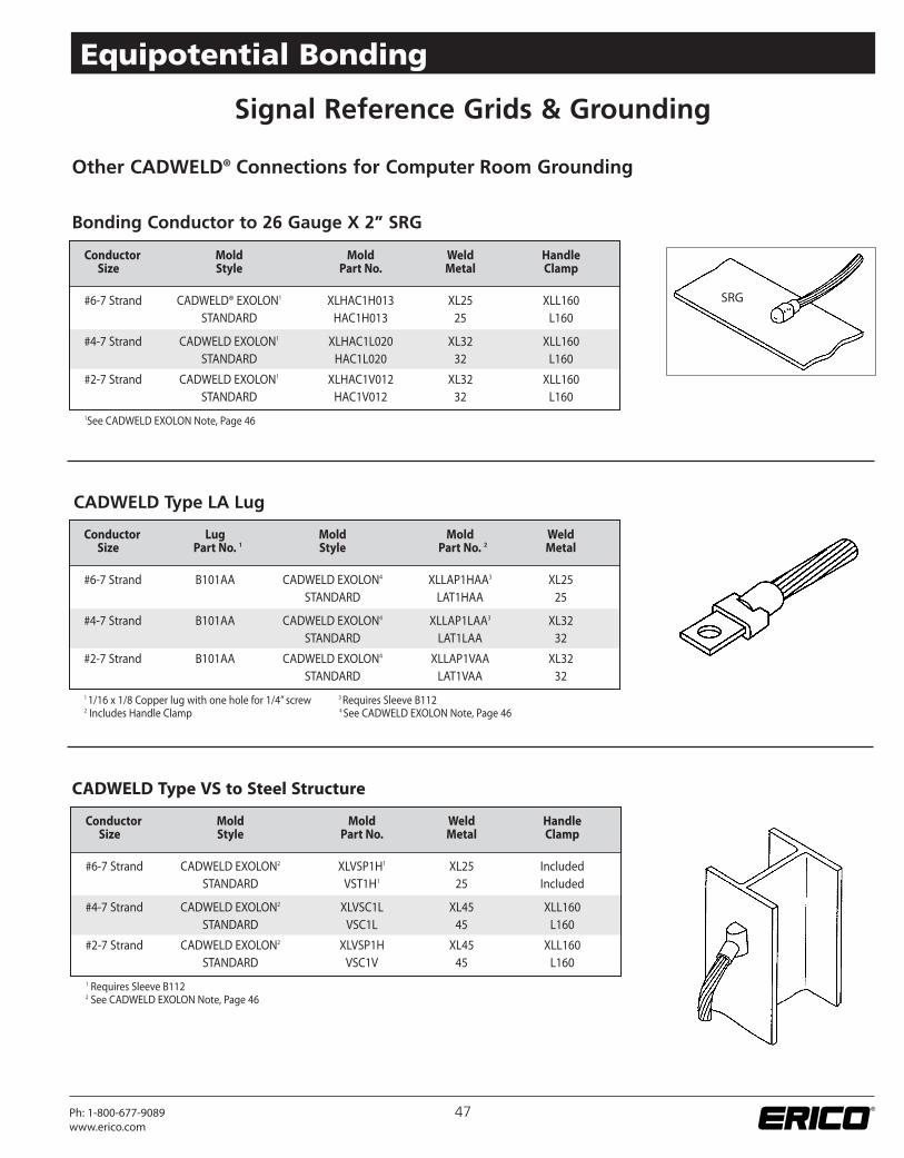
Bonding Conductor to 26 Gauge X 2” SRG
Signal Reference Grids & Grounding
Other CADWELD® Connections for Computer Room Grounding
Conductor Mold Mold Weld HandleSize Style Part No. Metal Clamp
#6-7 Strand CADWELD® EXOLON1 XLHAC1H013 XL25 XLL160STANDARD HAC1H013 25 L160
#4-7 Strand CADWELD EXOLON1 XLHAC1L020 XL32 XLL160STANDARD HAC1L020 32 L160
#2-7 Strand CADWELD EXOLON1 XLHAC1V012 XL32 XLL160STANDARD HAC1V012 32 L160
1See CADWELD EXOLON Note, Page 46
CADWELD Type LA Lug
CADWELD Type VS to Steel Structure
SRG
47Ph: 1-800-677-9089www.erico.com
Equipotential Bonding
Conductor Lug Mold Mold WeldSize Part No. 1 Style Part No. 2 Metal
#6-7 Strand B101AA CADWELD EXOLON4 XLLAP1HAA3 XL25STANDARD LAT1HAA 25
#4-7 Strand B101AA CADWELD EXOLON4 XLLAP1LAA3 XL32STANDARD LAT1LAA 32
#2-7 Strand B101AA CADWELD EXOLON4 XLLAP1VAA XL32STANDARD LAT1VAA 32
11/16 x 1/8 Copper lug with one hole for 1/4” screw 3Requires Sleeve B1122 Includes Handle Clamp 4See CADWELD EXOLON Note, Page 46
Conductor Mold Mold Weld HandleSize Style Part No. Metal Clamp
#6-7 Strand CADWELD EXOLON2 XLVSP1H1 XL25 IncludedSTANDARD VST1H1 25 Included
#4-7 Strand CADWELD EXOLON2 XLVSC1L XL45 XLL160STANDARD VSC1L 45 L160
#2-7 Strand CADWELD EXOLON2 XLVSP1H XL45 XLL160STANDARD VSC1V 45 L160
1 Requires Sleeve B1122 See CADWELD EXOLON Note, Page 46
Equipotential Mesh / Mats
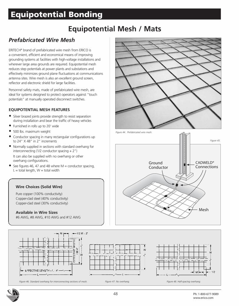
ERITECH® brand of prefabricated wire mesh from ERICO isa convenient, efficient and economical means of improvinggrounding systems at facilities with high-voltage installations andwherever large area grounds are required. Equipotential meshreduces step potentials at power plants and substations andeffectively minimizes ground plane fluctuations at communicationsantenna sites. Wire mesh is also an excellent ground screen,reflector and electronic shield for large facilities.
Personnel safety mats, made of prefabricated wire mesh, areideal for systems designed to protect operators against “touchpotentials” at manually operated disconnect switches.
EQUIPOTENTIAL MESH FEATURES
• Silver brazed joints provide strength to resist separationduring installation and bear the traffic of heavy vehicles
• Furnished in rolls up to 20’ wide
• 500 lbs. maximum weight
• Conductor spacing in many rectangular configurations upto 24” X 48” in 2” increments
• Normally supplied in sections with standard overhang forinterconnecting (1/2 conductor spacing + 2”)
It can also be supplied with no overhang or otheroverhang configurations.
• See figures 46, 47 and 48 where M = conductor spacing,L = total length, W = total width
Figure 47. No overhang.Figure 46. Standard overhang for interconnecting sections of mesh. Figure 48. Half-spacing overhang.
Prefabricated Wire Mesh
Wire Choices (Solid Wire)
Pure copper (100% conductivity)Copper-clad steel (40% conductivity)Copper-clad steel (30% conductivity)
Available in Wire Sizes#6 AWG, #8 AWG, #10 AWG and #12 AWG
Figure 44. Prefabricated wire mesh.
Figure 45.
48 Ph: 1-800-677-9089www.erico.com
Equipotential Bonding
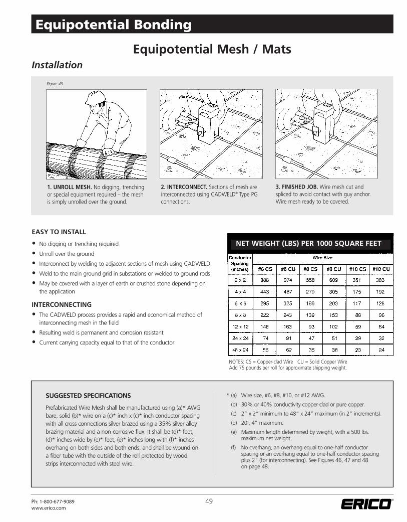
1. UNROLL MESH. No digging, trenchingor special equipment required – the meshis simply unrolled over the ground.
NOTES: CS = Copper-clad Wire CU = Solid Copper WireAdd 75 pounds per roll for approximate shipping weight.
EASY TO INSTALL
• No digging or trenching required
• Unroll over the ground
• Interconnect by welding to adjacent sections of mesh using CADWELD
• Weld to the main ground grid in substations or welded to ground rods
• May be covered with a layer of earth or crushed stone depending onthe application
INTERCONNECTING
• The CADWELD process provides a rapid and economical method ofinterconnecting mesh in the field
• Resulting weld is permanent and corrosion resistant
• Current carrying capacity equal to that of the conductor
Equipotential Mesh / MatsInstallation
SUGGESTED SPECIFICATIONS
Prefabricated Wire Mesh shall be manufactured using (a)* AWGbare, solid (b)* wire on a (c)* inch x (c)* inch conductor spacingwith all cross connections silver brazed using a 35% silver alloybrazing material and a non-corrosive flux. It shall be (d)* feet,(d)* inches wide by (e)* feet, (e)* inches long with (f)* inchesoverhang on both sides and both ends, and shall be wound ona fiber tube with the outside of the roll protected by woodstrips interconnected with steel wire.
2. INTERCONNECT. Sections of mesh areinterconnected using CADWELD® Type PGconnections.
3. FINISHED JOB. Wire mesh cut andspliced to avoid contact with guy anchor.Wire mesh ready to be covered.
NET WEIGHT (LBS) PER 1000 SQUARE FEETT
* (a) Wire size, #6, #8, #10, or #12 AWG.
(b) 30% or 40% conductivity copper-clad or pure copper.
(c) 2” x 2” minimum to 48” x 24” maximum (in 2” increments).
(d) 20’, 4” maximum.
(e) Maximum length determined by weight, with a 500 lbs.maximum net weight.
(f) No overhang, an overhang equal to one-half conductorspacing or an overhang equal to one-half conductor spacingplus 2” (for interconnecting). See Figures 46, 47 and 48on page 48.
Figure 49.
49Ph: 1-800-677-9089www.erico.com
Equipotential Bonding
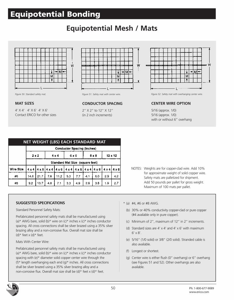
NET WEIGHT (LBS) EACH STANDARD MAT
SUGGESTED SPECIFICATIONS
Standard Personnel Safety Mats:
Prefabricated personnel safety mats shall be manufactured using(a)* AWG bare, solid (b)* wire on (c)* inches x (c)* inches conductorspacing. All cross connections shall be silver brazed using a 35% silverbrazing alloy and a non-corrosive flux. Overall mat size shall be(d)* feet x (d)* feet.
Mats With Center Wire:
Prefabricated personnel safety mats shall be manufactured using(a)* AWG bare, solid (b)* wire on (c)* inches x (c)* inches conductorspacing with (e)* diameter solid copper center wire through the(f)* length overhanging each end (g)* inches. All cross connectionsshall be silver brazed using a 35% silver brazing alloy and anon-corrosive flux. Overall mat size shall be (d)* feet x (d)* feet.
NOTES: Weights are for copper-clad wire. Add 10%for approximate weight of solid copper wire.Safety mats are palletized for shipment.Add 50 pounds per pallet for gross weight.Maximum of 100 mats per pallet.
* (a) #4, #6 or #8 AWG.
(b) 30% or 40% conductivity copper-clad or pure copper(#4 available only in pure copper).
(c) Minimum of 2”, maximum of 12” in 2” increments.
(d) Standard sizes are 4’ x 4’ and 4’ x 6’ with maximum6’ x 8’.
(e) 5/16” (1/0 solid) or 3/8” (2/0 solid). Stranded cable isalso available.
(f) Longest or shortest.
(g) Center wire is either flush (0” overhang) or 6” overhang(see Figures 51 and 52). Other overhangs are alsoavailable.
Equipotential Mesh / Mats
MAT SIZES
4’ X 4’ 4’ X 6’ 4’ X 6’Contact ERICO for other sizes
CONDUCTOR SPACING
2” X 2” to 12” X 12”(in 2 inch increments)
CENTER WIRE OPTION
5/16 (approx. 1/0)5/16 (approx. 1/0)with or without 6” overhang
Figure 51. Safety mat with center wire.Figure 50. Standard safety mat. Figure 52. Safety mat with overhanging center wire.
50 Ph: 1-800-677-9089www.erico.com
Equipotential Bonding
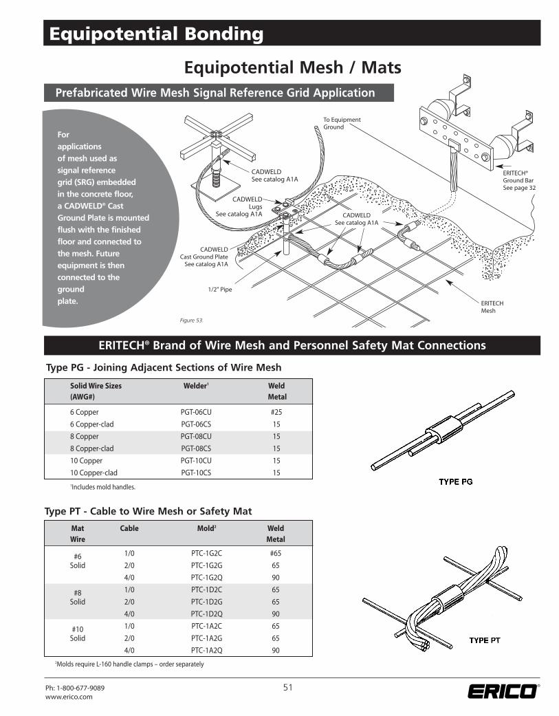
Forapplicationsof mesh used assignal referencegrid (SRG) embeddedin the concrete floor,a CADWELD® CastGround Plate is mountedflush with the finishedfloor and connected tothe mesh. Futureequipment is thenconnected to thegroundplate.
Prefabricated Wire Mesh Signal Reference Grid Application
ERITECHMesh
1/2" Pipe
CADWELDCast Ground PlateSee catalog A1A
CADWELDSee catalog A1A
CADWELDSee catalog A1A
To EquipmentGround
ERITECH®Ground BarSee page 32
CADWELDLugs
See catalog A1A
Type PG - Joining Adjacent Sections of Wire Mesh
ERITECH® Brand of Wire Mesh and Personnel Safety Mat Connections
Type PT - Cable to Wire Mesh or Safety Mat
Equipotential Mesh / Mats
SolidWire Sizes Welder1 Weld(AWG#) Metal
6 Copper PGT-06CU #25
6 Copper-clad PGT-06CS 15
8 Copper PGT-08CU 15
8 Copper-clad PGT-08CS 15
10 Copper PGT-10CU 15
10 Copper-clad PGT-10CS 151Includes mold handles.
Mat Cable Mold2 WeldWire Metal
#6 1/0 PTC-1G2C #65
Solid 2/0 PTC-1G2G 65
4/0 PTC-1G2Q 90
#8 1/0 PTC-1D2C 65
Solid 2/0 PTC-1D2G 65
4/0 PTC-1D2Q 90
#10 1/0 PTC-1A2C 65
Solid 2/0 PTC-1A2G 65
4/0 PTC-1A2Q 902Molds require L-160 handle clamps – order separately
Figure 53.
51Ph: 1-800-677-9089www.erico.com
Equipotential Bonding
Equipotential Mesh / Mats
52 Ph: 1-800-677-9089www.erico.com
Equipotential Bonding
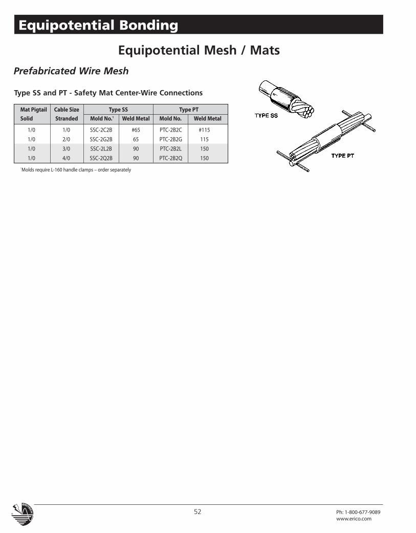
Mat Pigtail Cable Size Type SS Type PT
Solid Stranded Mold No.1 Weld Metal Mold No. Weld Metal
1/0 1/0 SSC-2C2B #65 PTC-2B2C #115
1/0 2/0 SSC-2G2B 65 PTC-2B2G 115
1/0 3/0 SSC-2L2B 90 PTC-2B2L 150
1/0 4/0 SSC-2Q2B 90 PTC-2B2Q 150
1Molds require L-160 handle clamps – order separately
Type SS and PT - Safety Mat Center-Wire Connections
Prefabricated Wire Mesh
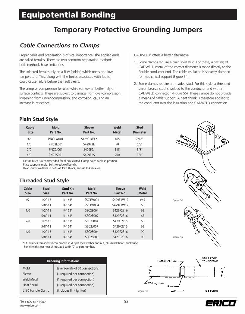
Proper cable end preparation is of vital importance. The applied endsare called ferrules. There are two common preparation methods –both methods have limitations.
The soldered ferrules rely on a filler (solder) which melts at a lowtemperature. This, along with the forces associated with faults,could cause failure before the fault clears.
The crimp or compression ferrules, while somewhat better, rely onsurface contacts. These are subject to damage from over-compression,loosening from under-compression, and corrosion, causing anincrease in resistance.
CADWELD® offers a better alternative.
1. Some clamps require a plain solid stud. For these, a casting ofCADWELD metal of the correct diameter is made directly to theflexible conductor end. The cable insulation is securely clampedfor mechanical support (Figure 54).
2. Some clamps require a threaded stud. For this style, a threadedsilicon bronze stud is welded to the conductor end with aCADWELD connection (Figure 55). These clamps do not providea means of cable support. A heat shrink is therefore applied tothe conductor over the insulation and CADWELD connection.
Plain Stud Style
Threaded Stud Style
Temporary Protective Grounding Jumpers
Cable Stud Stud Kit Mold Sleeve WeldSize Size Part No. Part No. Part No. Metal
#2 1/2”-13 K-163* SSC1W001 S429F1W12 #45
5/8”-11 K-164* SSC1W004 S429F1W12 65
1/0 1/2”-13 K-163* SSC2E004 S429F2E16 65
5/8”-11 K-164* SSC2E007 S429F2E16 65
2/0 1/2”-13 K-163* SSC2J004 S429F2J16 65
5/8”-11 K-164* SSC2J007 S429F2J16 65
4/0 1/2”-13 K-163* SSC2S004 S429F2S16 90
5/8”-11 K-164* SSC2S005 S429F2S16 90
*Kit includes threaded silicon bronze stud, split lock washer and nut, plus black heat shrink tube.For kit with clear heat shrink, add suffix “C” to part number.
Figure 54
Figure 55
Cable Mold Sleeve Weld StudSize Part No. Part No. Metal Diameter
#2 PNC1W001 S429F1W12 #65 7/16”
1/0 PNC2E001 S429F2E 90 5/8”
2/0 PNC2J001 S429F2J 115 5/8”
4/0 PNC2S001 S429F2S 200 3/4”
Fixture B523 is recommended for all sizes listed. Clamp holds cable in position.Plate supports mold. Bolts to edge of bench.Heat shrink available in both A130C1 (black) and A130A3 (clear).
Ordering information:
Mold (average life of 50 connections)
Sleeve (1 required per connection)
Weld Metal (1 required per connection)
Heat Shrink (1 required per connection)
L160 Handle Clamp (includes flint ignitor)
Cable Connections to Clamps
Figure 56
53Ph: 1-800-677-9089www.erico.com
Equipotential Bonding
Bonding Devices
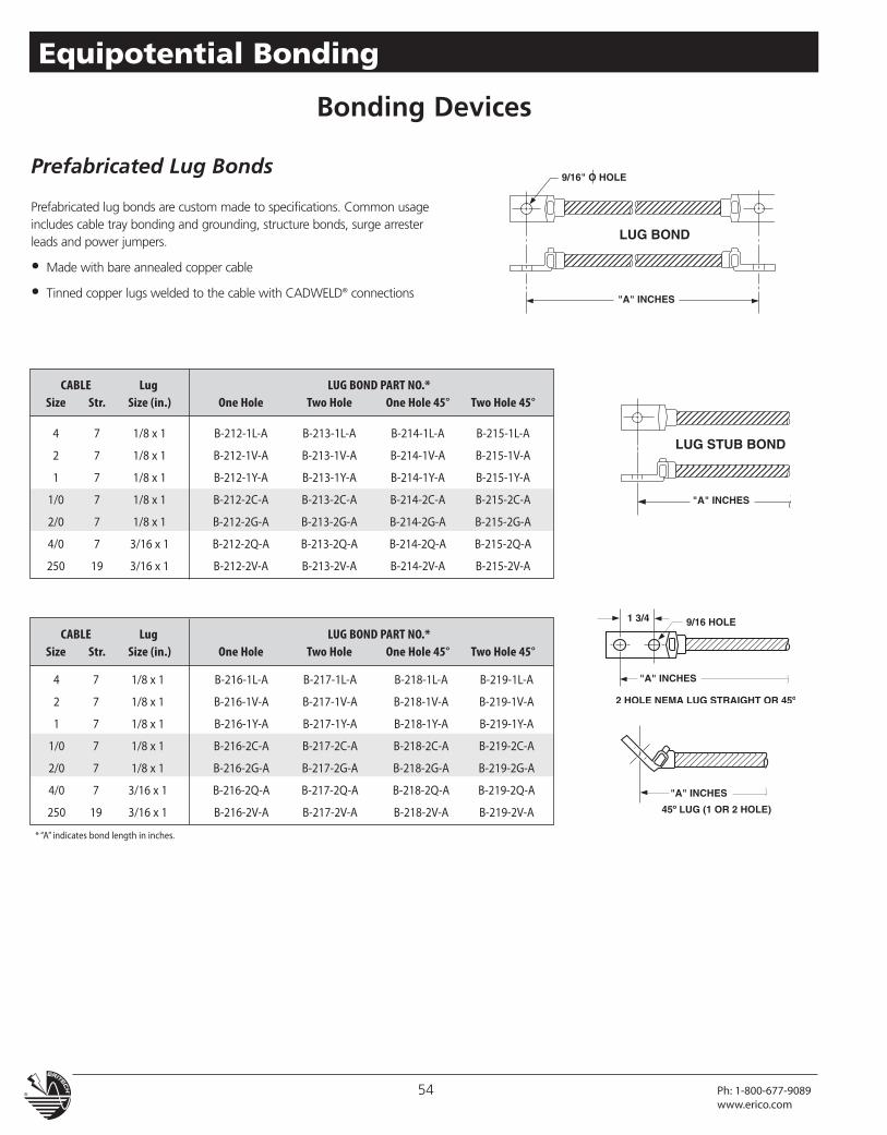
Prefabricated Lug Bonds
Prefabricated lug bonds are custom made to specifications. Common usageincludes cable tray bonding and grounding, structure bonds, surge arresterleads and power jumpers.
• Made with bare annealed copper cable
• Tinned copper lugs welded to the cable with CADWELD® connections
CABLE Lug LUG BOND PART NO.*Size Str. Size (in.) One Hole Two Hole One Hole 45° Two Hole 45°
4 7 1/8 x 1 B-212-1L-A B-213-1L-A B-214-1L-A B-215-1L-A
2 7 1/8 x 1 B-212-1V-A B-213-1V-A B-214-1V-A B-215-1V-A
1 7 1/8 x 1 B-212-1Y-A B-213-1Y-A B-214-1Y-A B-215-1Y-A
1/0 7 1/8 x 1 B-212-2C-A B-213-2C-A B-214-2C-A B-215-2C-A
2/0 7 1/8 x 1 B-212-2G-A B-213-2G-A B-214-2G-A B-215-2G-A
4/0 7 3/16 x 1 B-212-2Q-A B-213-2Q-A B-214-2Q-A B-215-2Q-A
250 19 3/16 x 1 B-212-2V-A B-213-2V-A B-214-2V-A B-215-2V-A
CABLE Lug LUG BOND PART NO.*Size Str. Size (in.) One Hole Two Hole One Hole 45° Two Hole 45°
4 7 1/8 x 1 B-216-1L-A B-217-1L-A B-218-1L-A B-219-1L-A
2 7 1/8 x 1 B-216-1V-A B-217-1V-A B-218-1V-A B-219-1V-A
1 7 1/8 x 1 B-216-1Y-A B-217-1Y-A B-218-1Y-A B-219-1Y-A
1/0 7 1/8 x 1 B-216-2C-A B-217-2C-A B-218-2C-A B-219-2C-A
2/0 7 1/8 x 1 B-216-2G-A B-217-2G-A B-218-2G-A B-219-2G-A
4/0 7 3/16 x 1 B-216-2Q-A B-217-2Q-A B-218-2Q-A B-219-2Q-A
250 19 3/16 x 1 B-216-2V-A B-217-2V-A B-218-2V-A B-219-2V-A
* “A” indicates bond length in inches.
54 Ph: 1-800-677-9089www.erico.com
Equipotential Bonding
Bonding Devices
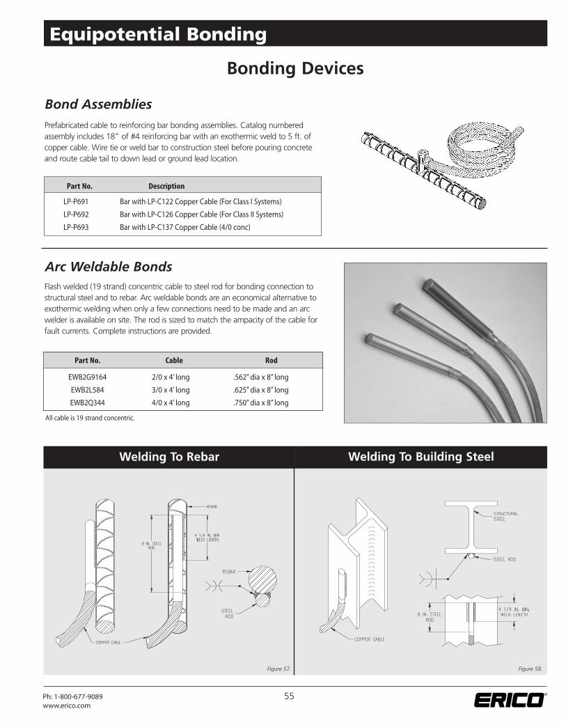
Prefabricated cable to reinforcing bar bonding assemblies. Catalog numberedassembly includes 18” of #4 reinforcing bar with an exothermic weld to 5 ft. ofcopper cable. Wire tie or weld bar to construction steel before pouring concreteand route cable tail to down lead or ground lead location.
Flash welded (19 strand) concentric cable to steel rod for bonding connection tostructural steel and to rebar. Arc weldable bonds are an economical alternative toexothermic welding when only a few connections need to be made and an arcwelder is available on site. The rod is sized to match the ampacity of the cable forfault currents. Complete instructions are provided.
Part No. Cable Rod
EWB2G9164 2/0 x 4’ long .562”dia x 8” long
EWB2L584 3/0 x 4’ long .625”dia x 8” long
EWB2Q344 4/0 x 4’ long .750”dia x 8” long
Welding To Rebar
Part No. Description
LP-P691 Bar with LP-C122 Copper Cable (For Class I Systems)
LP-P692 Bar with LP-C126 Copper Cable (For Class II Systems)
LP-P693 Bar with LP-C137 Copper Cable (4/0 conc)
Welding To Building Steel
Bond Assemblies
Arc Weldable Bonds
Figure 57. Figure 58.
55Ph: 1-800-677-9089www.erico.com
Equipotential Bonding
All cable is 19 strand concentric.
Temporary Protective Grounding Jumpers
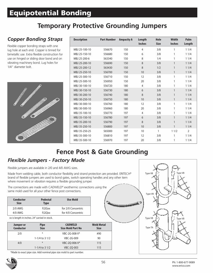
Copper Bonding StrapsFlexible copper bonding straps with onelug hole at each end. Copper is tinned forbimetallic use. Extra flexible construction foruse on hinged or sliding door bond and onvibrating machinery bond. Lug holes for1/4” diameter bolt.
Type VB
Type VB
Type VB
Type VB
Type VB
Type TA
Flexible jumpers are available in 2/0 and 4/0 AWG sizes.
Made from welding cable, both conductor flexibility and strand protection are provided. ERITECH®
brand of flexible jumpers are used to bond gates, switch operating handles and any other itemwhere movement or vibration requires a flexible grounding jumper.
The connections are made with CADWELD® exothermic connections using thesame mold used for all your other fence post connections.
Fence Post & Gate Grounding
Description Part Number Ampacity A Length Hole Width PalmInches Size Inches Length
MBJ 25-100-10 556670 150 4 3/8 1 1 1/4
MBJ 25-150-10 556680 150 6 3/8 1 1 1/4
MBJ 25-200-6 563340 150 8 1/4 1 1 1/4
MBJ 25-200-10 556690 150 8 3/8 1 1 1/4
MBJ 25-200-12 563430 150 8 1/2 1 1 1/4
MBJ 25-250-10 556700 150 10 3/8 1 1 1/4
MBJ 25-300-10 556710 150 12 3/8 1 1 1/4
MBJ 25-500-10 556950 150 20 3/8 1 1 1/4
MBJ 30-100-10 556720 180 4 3/8 1 1 1/4
MBJ 30-150-10 556730 180 6 3/8 1 1 1/4
MBJ 30-200-10 556740 180 8 3/8 1 1 1/4
MBJ 30-250-10 556750 180 10 3/8 1 1 1/4
MBJ 30-300-10 556760 180 12 3/8 1 1 1/4
MBJ 30-500-10 556960 180 20 3/8 1 1 1/4
MBJ 35-100-10 556770 197 4 3/8 1 1 1/4
MBJ 35-150-10 556780 197 6 3/8 1 1 1/4
MBJ 35-200-10 556790 197 8 3/8 1 1 1/4
MBJ 35-250-10 556800 197 10 3/8 1 1 1/4
MBJ 35-250-25 565000 197 10 1 1 1/2 2
MBJ 35-300-10 556810 197 12 3/8 1 1 1/4
MBJ 35-500-10 556970 197 20 3/8 1 1 1/4
Jumper or Pipe CADWELD Weld MetalConductor Size Size Mold Part No Size
2/0 * VBC-2G-008-V* #90
1-1/4 to 3 1/2 VBC-2G-009 90
4/0 * VBC-2Q-006-V* 115
1-1/4 to 3 1/2 VBC-2Q-003 115
*Made to exact pipe size. Add nominal pipe size mold to part number.
Conductor Pedestal Use MoldSize Type
2/0 AWG FJ2Gxx for 2/0 Concentric4/0 AWG FJ2Qxx for 4/0 Concentric
xx is length in inches. 24” carried in stock.
Flexible Jumpers - Factory Made
56 Ph: 1-800-677-9089www.erico.com
Equipotential Bonding
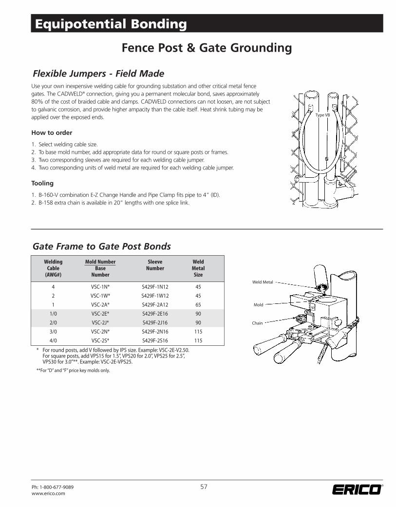
Weld Metal
Mold
Chain
Type VB
Use your own inexpensive welding cable for grounding substation and other critical metal fencegates. The CADWELD® connection, giving you a permanent molecular bond, saves approximately80% of the cost of braided cable and clamps. CADWELD connections can not loosen, are not subjectto galvanic corrosion, and provide higher ampacity than the cable itself. Heat shrink tubing may beapplied over the exposed ends.
How to order
1. Select welding cable size.2. To base mold number, add appropriate data for round or square posts or frames.3. Two corresponding sleeves are required for each welding cable jumper.4. Two corresponding units of weld metal are required for each welding cable jumper.
Tooling
1. B-160-V combination E-Z Change Handle and Pipe Clamp fits pipe to 4” (ID).2. B-158 extra chain is available in 20” lengths with one splice link.
Fence Post & Gate Grounding
Welding Mold Number Sleeve WeldCable Base Number Metal
(AWG#) Number Size
4 VSC-1N* S429F-1N12 45
2 VSC-1W* S429F-1W12 45
1 VSC-2A* S429F-2A12 65
1/0 VSC-2E* S429F-2E16 90
2/0 VSC-2J* S429F-2J16 90
3/0 VSC-2N* S429F-2N16 115
4/0 VSC-2S* S429F-2S16 115
* For round posts, add V followed by IPS size. Example: VSC-2E-V2.50.For square posts, add VPS15 for 1.5”, VPS20 for 2.0”, VPS25 for 2.5”,VPS30 for 3.0”**. Example: VSC-2E-VPS25.
**For “D” and “F” price key molds only.
Flexible Jumpers - Field Made
Gate Frame to Gate Post Bonds
57Ph: 1-800-677-9089www.erico.com
Equipotential Bonding
“X”Conductor Coding
Size Code
1/0 2C
2/0 2G
4/0 2Q
7/#7 9C
7/#5 9E
19/#9 9F
Fence Post & Gate Grounding
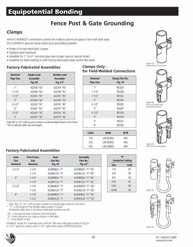
Figure 59.Field-made Connections
Figure 60.With a Ground Lead(Left Hand Shown)
Figure 61.With Two Ground Leads
When CADWELD® connections cannot be made to aluminum pipe or thin-wall steel tube,the CADWELD ground clamp solves your grounding problem.
• Made of tinned electrolytic copper• Stainless-steel hardware• Available for 1” to 4” nominal pipe sizes (Larger sizes on special order)• Available for field welding or with factory-fabricated cable and/or flex leads
1Add “RH”or “LH” suffix to part number to indicate Right Hand or Left Hand.*“XL” is code for cable size and length.
Factory-Fabricated Assemblies Clamps Only -for Field-Welded Connections
Clamps
Nominal Clamp Part No.Pipe Size Fig. 59
1” B522A
1-1/4” B522B
1-1/2” B522C
2” B522D
2-1/2” B522E
3” B522F
3-1/2” B522G
4” B522H
5” B522J
6” B522K
Nominal Single Lead Double LeadPipe Size Assembly1 Assembly1
Fig. 60 Fig. 61*
1” A235A- “XL” A237A- “XL”
1-1/4” A235B- “XL” A237B- “XL”
1-1/2” A235C- “XL” A237C- “XL”
2” A235D- “XL” A237D- “XL”
2-1/2” A235E- “XL” A237E- “XL”
3” A235F- “XL” A237F- “XL”
3-1/2” A235G- “XL” A237G- “XL”
4” A235H- “XL” A237H- “XL”
Cable Mold W/M
1/0 LAC2C002 #65
2/0 LAC2G002 #65
4/0 LAC2Q002 #90
Gate Post Frame Gate AssemblySize Size Part No.1 Part No.1
Nominal Nominal Fig. 62 Fig. 63*
2-1/2” 1-1/4” A238EB2S- “Y” A239EB2S- “Y”-“XL”
1-1/2” A238EC2S- “Y” A239EC2S- “Y”-“XL”
3” 1-1/4” A238FB2S- “Y” A239FB2S- “Y”-“XL”
1-1/2” A238FC2S- “Y” A239FC2S- “Y”-“XL”
3-1/2” 1-1/4” A238GB2S- “Y” A239GB2S- “Y”-“XL”
1-1/2” A238GC2S- “Y” A239GC2S- “Y”-“XL”
4” 1-1/4” A238HB2S- “Y” A239HB2S- “Y”-“XL”
1-1/2” A238HC2S- “Y” A239HC2S- “Y”-“XL”
1 Add “RH” or “LH” suffix to part number to indicate Right Hand or Left Hand* “Y” is the length of the flexible cable jumper in inches.
All flexible cable sizes in the above listed part numbers are 4/0.
“XL” is the ground lead conductor size and length“X” is the conductor size code as shown in the table.“L” is the length in feet.
EXAMPLE: Figure 63. Assembly with a 4/0 24” flex and a 4/0 ground lead 4’ long toa 3-1/2” gate post clamp, and a 1-1/2” gate frame clamp A239GC2S242Q4.
Factory-Fabricated Assemblies
Figure 62.
Figure 63.
58 Ph: 1-800-677-9089www.erico.com
Equipotential Bonding
Examples for CADWELD® Molds:
1. A 4” outside-diameter pipe is a 3-1/2” nominalpipe size. The mold number for a 4/0 concentricconductor to this pipe would be:
VSC-2Q-V 3.50
2. A nominal 2 x 2-1/4” H section uses mold code PH2.A 4/0 Type VB weld to this post would be VBC-2Q-PH2.
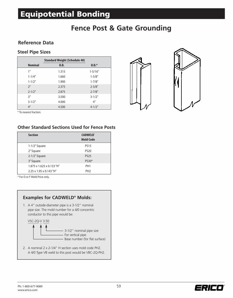
* To nearest fraction.
Steel Pipe Sizes
Reference Data
* For D or F Mold Price only.
Other Standard Sections Used for Fence Posts
Fence Post & Gate Grounding
3-1/2” nominal pipe sizeFor vertical pipeBase number (for flat surface)
Standard Weight (Schedule 40)
Nominal O.D. O.D.*
1” 1.315 1-5/16”
1-1/4” 1.660 1-5/8”
1-1/2” 1.900 1-7/8”
2” 2.375 2-3/8”
2-1/2” 2.875 2-7/8”
3” 3.500 3-1/2”
3-1/2” 4.000 4”
4” 4.500 4-1/2”
Section CADWELD®
Mold Code
1-1/2” Square PS15
2” Square PS20
2-1/2” Square PS25
3” Square PS30*
1.875 x 1.625 x 0.133 “H” PH1
2.25 x 1.95 x 0.143 “H” PH2
59Ph: 1-800-677-9089www.erico.com
Equipotential Bonding