Embed Size (px)
Citation preview
INSTALLATION INSTRUCTIONSPART NUMBER:
21-448B (Blue Finish) 21-448C (Gun Metal Grey Finish)
21-448P (Vauum Metalized Chrome-VMC) 21-448R (Red Finish)
AEM Induction Systems 1 (800) 992-3000 WWW: http://www.aemintakes.com
2002-2004 CHEVROLET Cavalier Ecotec L4-2.2L C.A.R.B. E.O. # D-670-15 2002-2005 PONTIAC SunfireEcotec L4-2.2L C.A.R.B.E.O.#D-670-15
Equipped with AEM® Dryflow™ FilterNo Oil Required!
2
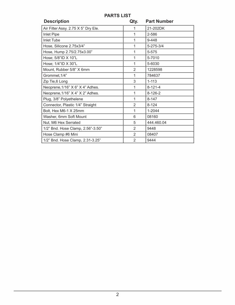
Description Qty. Part NumberPARTS LIST
Air Filter Assy. 2.75 X 5” Dry Ele. 1 21-202DKInlet Pipe 1 2-586Inlet Tube 1 9-448Hose, Silicone 2.75x3/4” 1 5-275-3/4Hose, Hump 2.75/2.75x3.00” 1 5-575Hose; 5/8”ID X 10”L 1 5-7010Hose; 1/4”ID X 30”L 1 5-6030Mount, Rubber 5/8” X 6mm 2 1228598Grommet,1/4” 1 784637Zip Tie,6 Long 3 1-113Neoprene,1/16” X 6” X 4” Adhes. 1 8-121-4Neoprene,1/16” X 4” X 2” Adhes. 1 8-126-2Plug, 3/8” Polyethelene 1 8-147Connector, Plastic 1/4” Straight 2 8-124Bolt, Hex M6-1 X 25mm 1 1-2044Washer, 6mm Soft Mount 6 08160Nut, M6 Hex Serrated 5 444.460.041/2” Bnd. Hose Clamp, 2.56”-3.50” 2 9448Hose Clamp #6 Mini 2 084071/2” Bnd. Hose Clamp, 2.31-3.25” 2 9444
3
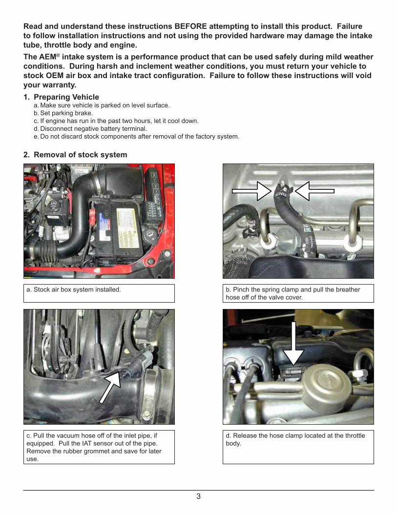
1. Preparing Vehicle a. Make sure vehicle is parked on level surface. b. Set parking brake. c. If engine has run in the past two hours, let it cool down. d. Disconnect negative battery terminal. e. Do not discard stock components after removal of the factory system. 2. Removal of stock system
Read and understand these instructions BEFORE attempting to install this product. Failureto follow installation instructions and not using the provided hardware may damage the intake tube, throttle body and engine.The AEM® intake system is a performance product that can be used safely during mild weather conditions. During harsh and inclement weather conditions, you must return your vehicle to stock OEM air box and intake tract configuration. Failure to follow these instructions will void your warranty.
a. Stock air box system installed. b. Pinch the spring clamp and pull the breather hose off of the valve cover.
c. Pull the vacuum hose off of the inlet pipe, if equipped. Pull the IAT sensor out of the pipe.Remove the rubber grommet and save for later use.
d. Release the hose clamp located at the throttle body.
4
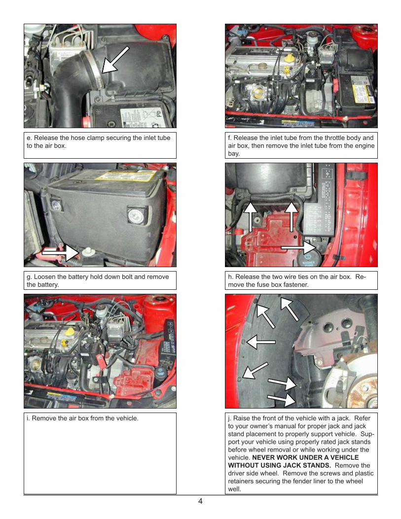
e. Release the hose clamp securing the inlet tube to the air box.
f. Release the inlet tube from the throttle body and air box, then remove the inlet tube from the engine bay.
g. Loosen the battery hold down bolt and remove the battery.
h. Release the two wire ties on the air box. Re-move the fuse box fastener.
i. Remove the air box from the vehicle. j. Raise the front of the vehicle with a jack. Refer to your owner’s manual for proper jack and jack stand placement to properly support vehicle. Sup-port your vehicle using properly rated jack stands before wheel removal or while working under the vehicle. NEVER WORK UNDER A VEHICLE WITHOUT USING JACK STANDS. Remove the driver side wheel. Remove the screws and plastic retainers securing the fender liner to the wheel well.
5
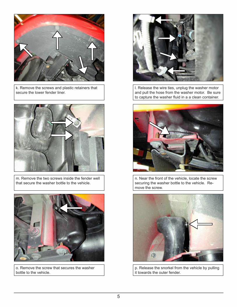
o. Remove the screw that secures the washer bottle to the vehicle.
k. Remove the screws and plastic retainers that secure the lower fender liner.
l. Release the wire ties, unplug the washer motor and pull the hose from the washer motor. Be sure tocapturethewasherfluidinaacleancontainer.
m. Remove the two screws inside the fender well that secure the washer bottle to the vehicle.
n. Near the front of the vehicle, locate the screw securing the washer bottle to the vehicle. Re-move the screw.
p. Release the snorkel from the vehicle by pulling it towards the outer fender.
6
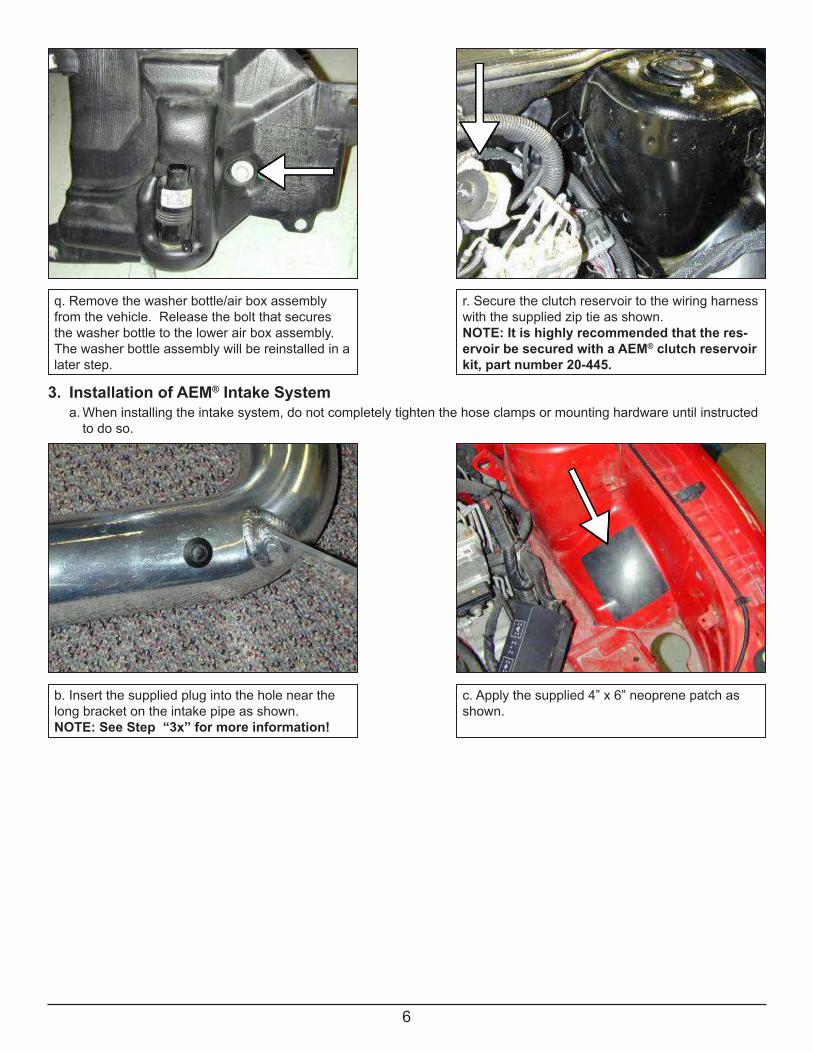
q. Remove the washer bottle/air box assembly from the vehicle. Release the bolt that secures the washer bottle to the lower air box assembly. The washer bottle assembly will be reinstalled in a later step.
r. Secure the clutch reservoir to the wiring harness with the supplied zip tie as shown.NOTE: It is highly recommended that the res-ervoir be secured with a AEM® clutch reservoir kit, part number 20-445.
3. Installation of AEM® Intake System a. When installing the intake system, do not completely tighten the hose clamps or mounting hardware until instructed to do so.
b. Insert the supplied plug into the hole near the long bracket on the intake pipe as shown. NOTE: See Step “3x” for more information!
c. Apply the supplied 4” x 6” neoprene patch as shown.

7
d. Install the rubber mount from inside the engine bay as shown.
e. Secure the other end inside the fender with thesupplied washer and lock nut.
f. Install the supplied bolt and washer through the hole in the fender well located near the strut tower. Secure the other side with a washer and lock nut.
g. Place the intake pipe in engine bay as shown. Do not tighten any bolts or nuts.
h.Affixthe2”x4”neoprenepatchtoprotecttheintake pipe as shown. It may be easier to mark the pipe, remove it from the vehicle and thenapply the patch.
i. Ensure the neoprene patch protects the intake pipe from the fender metal.
8
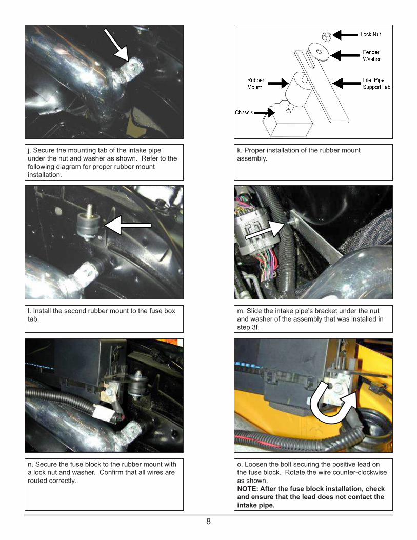
j. Secure the mounting tab of the intake pipe under the nut and washer as shown. Refer to the following diagram for proper rubber mountinstallation.
l. Install the second rubber mount to the fuse box tab.
m. Slide the intake pipe’s bracket under the nut and washer of the assembly that was installed in step 3f.
n. Secure the fuse block to the rubber mount with alocknutandwasher.Confirmthatallwiresarerouted correctly.
o. Loosen the bolt securing the positive lead on the fuse block. Rotate the wire counter-clockwise as shown.NOTE: After the fuse block installation, check and ensure that the lead does not contact the intake pipe.
k. Proper installation of the rubber mountassembly.
9
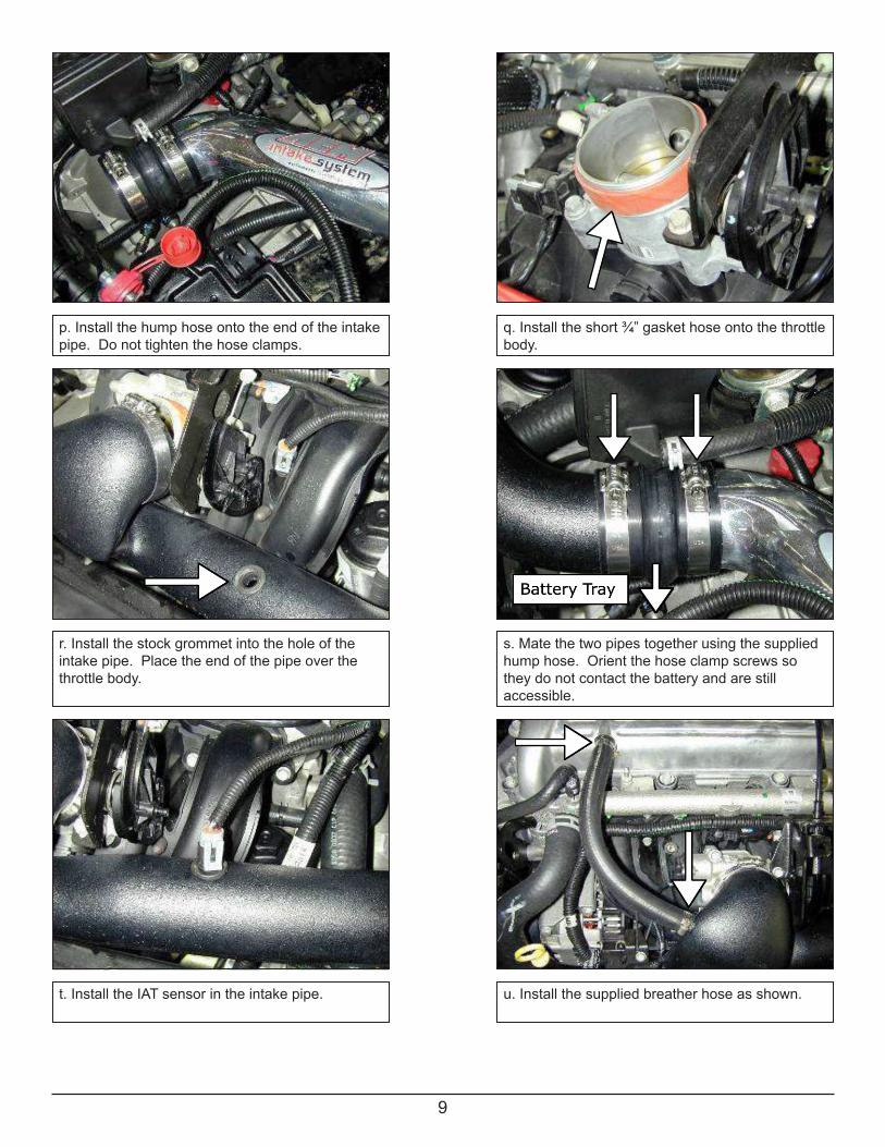
p. Install the hump hose onto the end of the intake pipe. Do not tighten the hose clamps.
q. Install the short ¾” gasket hose onto the throttle body.
r. Install the stock grommet into the hole of the intake pipe. Place the end of the pipe over the throttle body.
s. Mate the two pipes together using the supplied hump hose. Orient the hose clamp screws so they do not contact the battery and are stillaccessible.
t. Install the IAT sensor in the intake pipe. u. Install the supplied breather hose as shown.
10
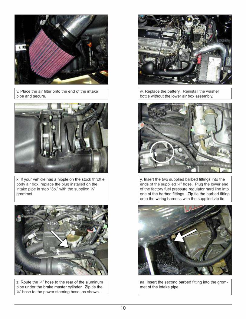
v.Placetheairfilterontotheendoftheintakepipe and secure.
w. Replace the battery. Reinstall the washer bottle without the lower air box assembly.
x. If your vehicle has a nipple on the stock throttle body air box, replace the plug installed on the intake pipe in step “3b.” with the supplied ¼” grommet.
y.Insertthetwosuppliedbarbedfittingsintotheends of the supplied ¼” hose. Plug the lower end of the factory fuel pressure regulator hard line into oneofthebarbedfittings.Ziptiethebarbedfittingonto the wiring harness with the supplied zip tie.
z. Route the ¼” hose to the rear of the aluminum pipe under the brake master cylinder. Zip tie the ¼” hose to the power steering hose, as shown.
aa.Insertthesecondbarbedfittingintothegrom-met of the intake pipe.
11
4. Reassemble Vehicle a. Washer Bottle:Fillthewasherbottlewiththewindshieldwasherfluidthatwasdrainedinstep2l. b. Fender liner: Install the fender liner and any hardware that was removed in steps 2j through 2k. NOTE: Failure to install the fender liner will result in diminished performance and increase the potential for engine damage due to water ingestion in rainy conditions. c. Wheel: Installthedriversidewheelusingthefactorytorquespecification(seeowner’smanual). d.Positiontheinletpipesforthebestfitment.Besurethatthepipesoranyothercomponentsdonotcontactanypart of the vehicle. Tighten the rubber mount, all bolts, and hose clamps. e. Check for proper hood clearance. Re-adjust pipes if necessary and re-tighten them. f. Inspect the engine bay for any loose tools and check that all fasteners that were moved or removed are properly tightened. g.Reconnectbatteryterminalsandstartengine.Letthevehicleidlefor3minutes.Performafinalinspection before driving the vehicle.
5. CARB Sticker Placement a. The C.A.R.B. exemption sticker, (attached), must be visible under the hood so that an emissions inspector can see it when the vehicle is required to be tested for emissions. California requires testing every two years, other states may vary.
6. Service and Maintenance a.AEMInductionSystemsrequirescleaningtheintakesystem’sairfilterelementevery100,000miles.Whenusedin dustyoroff-roadenvironments,ourfilterswillrequirecleaningmoreoften.Werecommendthatyouvisuallyinspect yourfilteronceevery25,000milestodetermineifthescreenisstillvisible.Whenthescreenisnolongervisible someplaceonthefilterelement,itistimetocleanit.Toclean,purchaseourSyntheticairfiltercleaner,partnumber 99-0624 and follow the easy instructions. b. Use window cleaner to clean your powder coated AEM® intake tube. NOTE: DO NOT USE aluminum polish on powder coated AEM® intake tubes.
AEM Air Intake System Warranty PolicyAEM® warrants that its intake systems will last for the life of your vehicle. AEM will not honor this warranty due to mechani-caldamage(i.e.improperinstallationorfitment),damagefrommisuse,accidentsorflyingdebris.AEMwillnotwarrantitspowdercoatingifthefinishhasbeencleanedwithahydrocarbon-basedsolvent.Thepowdercoatingshouldonlybecleaned with a mild soap and water solution. Proof of purchase of both the vehicle and AEM intake system is required for redemption of a warranty claim.
This warranty is limited to the repair or replacement of the AEM part. In no event shall this warranty exceed the original purchase price of the AEM part nor shall AEM be responsible for special, incidental or consequential damages or cost incurred due to the failure of this product. Warranty claims to AEM must be transportation prepaid and accompanied with dated proof of purchase. This warranty applies only to the original purchaser of product and is nontransferable. Improper use or installation, use for racing, accident, abuse, unauthorized repairs or alterations voids this warranty. AEM disclaims any liability for consequential damages due to breach of any written or implied warranty on all products manufactured by AEM. Warranty returns will only be accepted by AEM when accompanied by a valid Return Merchandise Authorization (RMA) number. Credit for defective products will be issued pending inspection. Product must be received by AEM within 30 days of the date RMA is issued.
If you have a warranty issue, please call (800) 992-3000 and our customer service department will assist you. A proof of purchase is required for all AEM warranty claims.
For technical inquiriese-mail us at
call us at800.992.3000
10-7011E08/25/14