Embed Size (px)
Citation preview
1
ER Series NEMA 4, 4X, 7
Electric Actuators Maximum 14040 in-lbs
Features
• ISO / DIN valve interface
• Mounting in any position
• Thermal overload protection (AC & DC except 12 VDC)
• Friction brake (standard for AC motors except 24 VAC)
• Permanent lubrication
• Reversing permanent split capacitor motors
• Manual override handwheel standard most sizes / housing
• Many options including: auxiliary limit switches, 4-20 mA positioner, power off brake, heater, heater & thermostat, light indicator, feedback potentiometer, speed control, timer, two-wire control relay
Quick Spec
Product Scope
Size Range ER1, 2, 3, 4, 6, 10, 15, 20, 38, 50, 70, 120, 140
Maximum Operating Torque
ER1: up to 100 in-lbs ER140: up to 14040 in-lbs
Cycle Time 2.5 - 58 sec. (varies with size, voltage, duty cycle, installed accessories)
Motor Voltage 24, 115, 230 VAC; 24 VDC
Duty Cycle ER1 – ER15: 25% ER20 – ER140: 100%
Enclosures NEMA 4, 4X, 7Temperature -40°F to +150°F (-40°C to +65°C)
Limit Swtiches (Open-Close & Aux.)
(125/250 VAC) 15A, 0.5 HP; (125VDC) 0.1A
Terminal Strip Connection 8 pt. AWG14
Materials(Housing) Die Cast Aluminum
(Gears) Heavy Duty Hardened Steel(Hardware) 300 Series SS
Finish Thermally Bonded Polyester CoatingDesign Standards*
CSA File No. LR 79567 (See Eng. data for applicability)
Mounting Flange (Valve) ISO 5211
ER- Series
* Varies with size, enclosure, voltage, installed accessories; see Engineering data for detailed specifications
2
ER Series Electric Actuators
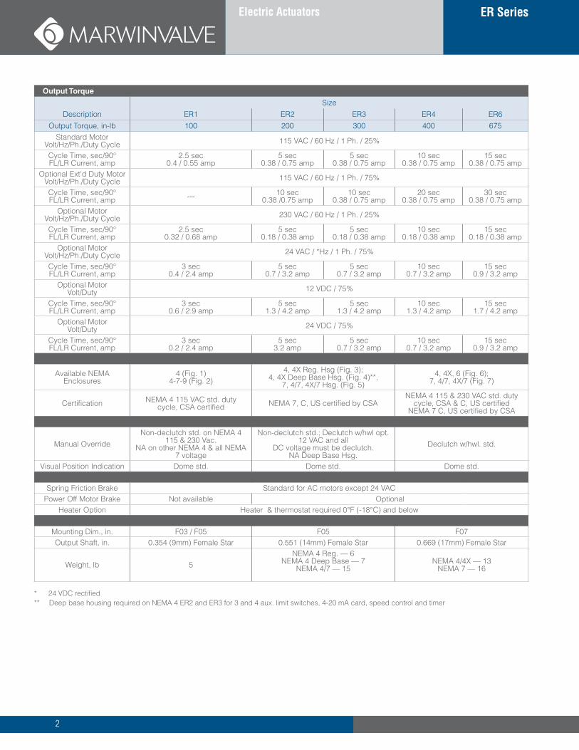
Output Torque
SizeDescription ER1 ER2 ER3 ER4 ER6
Output Torque, in-lb 100 200 300 400 675Standard Motor
Volt/Hz/Ph./Duty Cycle 115 VAC / 60 Hz / 1 Ph. / 25%
Cycle Time, sec/90° FL/LR Current, amp
2.5 sec 0.4 / 0.55 amp
5 sec 0.38 / 0.75 amp
5 sec 0.38 / 0.75 amp
10 sec0.38 / 0.75 amp
15 sec0.38 / 0.75 amp
Optional Ext'd Duty MotorVolt/Hz/Ph./Duty Cycle 115 VAC / 60 Hz / 1 Ph. / 75%
Cycle Time, sec/90° FL/LR Current, amp --- 10 sec
0.38 /0.75 amp10 sec
0.38 / 0.75 amp20 sec
0.38 / 0.75 amp30 sec
0.38 / 0.75 ampOptional Motor
Volt/Hz/Ph./Duty Cycle 230 VAC / 60 Hz / 1 Ph. / 25%
Cycle Time, sec/90° FL/LR Current, amp
2.5 sec0.32 / 0.68 amp
5 sec0.18 / 0.38 amp
5 sec0.18 / 0.38 amp
10 sec0.18 / 0.38 amp
15 sec0.18 / 0.38 amp
Optional MotorVolt/Hz/Ph./Duty Cycle 24 VAC / *Hz / 1 Ph. / 75%
Cycle Time, sec/90° FL/LR Current, amp
3 sec0.4 / 2.4 amp
5 sec0.7 / 3.2 amp
5 sec0.7 / 3.2 amp
10 sec0.7 / 3.2 amp
15 sec0.9 / 3.2 amp
Optional MotorVolt/Duty 12 VDC / 75%
Cycle Time, sec/90° FL/LR Current, amp
3 sec0.6 / 2.9 amp
5 sec1.3 / 4.2 amp
5 sec1.3 / 4.2 amp
10 sec1.3 / 4.2 amp
15 sec1.7 / 4.2 amp
Optional MotorVolt/Duty 24 VDC / 75%
Cycle Time, sec/90° FL/LR Current, amp
3 sec0.2 / 2.4 amp
5 sec3.2 amp
5 sec0.7 / 3.2 amp
10 sec0.7 / 3.2 amp
15 sec0.9 / 3.2 amp
Available NEMAEnclosures
4 (Fig. 1)4-7-9 (Fig. 2)
4, 4X Reg. Hsg (Fig. 3);4, 4X Deep Base Hsg. (Fig. 4)**,
7, 4/7, 4X/7 Hsg. (Fig. 5)4, 4X, 6 (Fig. 6);
7, 4/7, 4X/7 (Fig. 7)
Certification NEMA 4 115 VAC std. duty cycle, CSA certified NEMA 7, C, US certified by CSA
NEMA 4 115 & 230 VAC std. duty cycle, CSA & C, US certified
NEMA 7 C, US certified by CSA
Manual Override Non-declutch std. on NEMA 4
115 & 230 Vac. NA on other NEMA 4 & all NEMA
7 voltage
Non-declutch std.; Declutch w/hwl opt. 12 VAC and all
DC voltage must be declutch. NA Deep Base Hsg.
Declutch w/hwl. std.
Visual Position Indication Dome std. Dome std. Dome std.
Spring Friction Brake Standard for AC motors except 24 VAC Power Off Motor Brake Not available Optional
Heater Option Heater & thermostat required 0°F (-18°C) and below
Mounting Dim., in. F03 / F05 F05 F07Output Shaft, in. 0.354 (9mm) Female Star 0.551 (14mm) Female Star 0.669 (17mm) Female Star
Weight, lb 5NEMA 4 Reg. — 6
NEMA 4 Deep Base — 7NEMA 4/7 — 15
NEMA 4/4X — 13NEMA 7 — 16
* 24 VDC rectified** Deep base housing required on NEMA 4 ER2 and ER3 for 3 and 4 aux. limit switches, 4-20 mA card, speed control and timer
3
ER Series NEMA 4, 4X, 7
Electric Actuators Maximum 14040 in-lbs
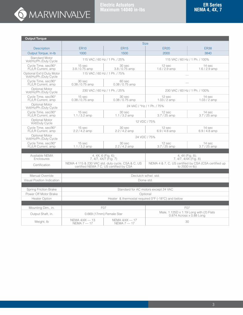
Output Torque
SizeDescription ER10 ER15 ER20 ER38
Output Torque, in-lb 1000 1500 2000 3840Standard Motor
Volt/Hz/Ph./Duty Cycle 115 VAC / 60 Hz / 1 Ph. / 25% 115 VAC / 60 Hz / 1 Ph. / 100%
Cycle Time, sec/90° FL/LR Current, amp
15 sec3.8 / 0.75 amp
30 sec3.8 / 0.75 amp
12 sec1.6 / 2.9 amp
14 sec1.6 / 2.9 amp
Optional Ext'd Duty MotorVolt/Hz/Ph./Duty Cycle
115 VAC / 60 Hz / 1 Ph. / 75% —
Cycle Time, sec/90° FL/LR Current, amp
30 sec0.38 / 0.75 amp
60 sec0.38 / 0.75 amp —
Optional MotorVolt/Hz/Ph./Duty Cycle 230 VAC / 60 Hz / 1 Ph. / 25% 230 VAC / 60 Hz / 1 Ph. / 100%
Cycle Time, sec/90° FL/LR Current, amp
15 sec0.38 / 0.75 amp
30 sec0.38 / 0.75 amp
12 sec1.03 / 2 amp
14 sec1.03 / 2 amp
Optional MotorVolt/Hz/Ph./Duty Cycle 24 VAC / *Hz / 1 Ph. / 75%
Cycle Time, sec/90° FL/LR Current, amp
15 sec1.1 / 3.2 amp
30 sec1.1 / 3.2 amp
12 sec3.7 / 25 amp
14 sec3.7 / 25 amp
Optional MotorVolt/Duty Cycle 12 VDC / 75%
Cycle Time, sec/90° FL/LR Current, amp
15 sec2.2 / 4.2 amp
30 sec2.2 / 4.2 amp
12 sec6.9 / 4.8 amp
14 sec6.9 / 4.8 amp
Optional MotorVolt/Hz/Ph./Duty Cycle 24 VDC / 75%
Cycle Time, sec/90° FL/LR Current, amp
15 sec1.1 / 3.2 amp
30 sec2.2 / 4.2 amp
12 sec3.7 / 25 amp
14 sec3.7 / 25 amp
Available NEMAEnclosures
4, 4X, 6 (Fig. 6);7, 4/7, 4X/7 (Fig. 7)
4, 4X (Fig. 8);7, 4/7, 4/4X (Fig. 8)
Certification NEMA 4 115 & 230 VAC std. duty cycle, CSA & C, US certified NEMA 7 C, US certified by CSA
NEMA 4 & 7, C, US certified by CSA (CSA certified up to 2000 in-lb)
Manual Override Declutch w/hwl. std.Visual Position Indication Dome std.
Spring Friction Brake Standard for AC motors except 24 VAC Power Off Motor Brake Optional
Heater Option Heater & thermostat required 0°F (-18°C) and below
Mounting Dim., in. F07 F07
Output Shaft, in. 0.669 (17mm) Female Star Male, 1.125D x 1.19 Long with (2) Flats0.874 Across x 0.88 Long
Weight, lb NEMA 4/4X — 13NEMA 7 — 17
NEMA 4/4X — 17NEMA 7 — 17 30
4
ER Series Electric Actuators
Output Torque
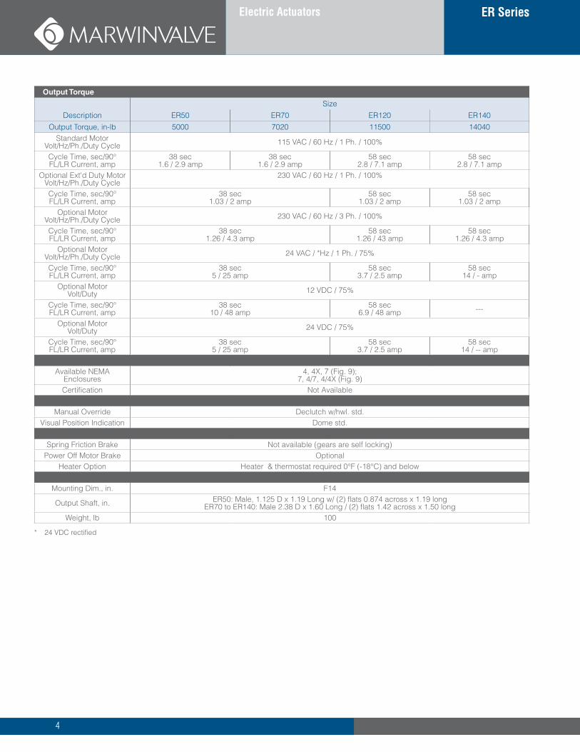
SizeDescription ER50 ER70 ER120 ER140
Output Torque, in-lb 5000 7020 11500 14040Standard Motor
Volt/Hz/Ph./Duty Cycle 115 VAC / 60 Hz / 1 Ph. / 100%
Cycle Time, sec/90° FL/LR Current, amp
38 sec1.6 / 2.9 amp
38 sec1.6 / 2.9 amp
58 sec2.8 / 7.1 amp
58 sec2.8 / 7.1 amp
Optional Ext'd Duty MotorVolt/Hz/Ph./Duty Cycle
230 VAC / 60 Hz / 1 Ph. / 100%
Cycle Time, sec/90° FL/LR Current, amp
38 sec1.03 / 2 amp
58 sec1.03 / 2 amp
58 sec1.03 / 2 amp
Optional MotorVolt/Hz/Ph./Duty Cycle 230 VAC / 60 Hz / 3 Ph. / 100%
Cycle Time, sec/90° FL/LR Current, amp
38 sec1.26 / 4.3 amp
58 sec1.26 / 43 amp
58 sec1.26 / 4.3 amp
Optional MotorVolt/Hz/Ph./Duty Cycle 24 VAC / *Hz / 1 Ph. / 75%
Cycle Time, sec/90° FL/LR Current, amp
38 sec5 / 25 amp
58 sec3.7 / 2.5 amp
58 sec14 / - amp
Optional MotorVolt/Duty 12 VDC / 75%
Cycle Time, sec/90° FL/LR Current, amp
38 sec10 / 48 amp
58 sec6.9 / 48 amp ---
Optional MotorVolt/Duty 24 VDC / 75%
Cycle Time, sec/90° FL/LR Current, amp
38 sec5 / 25 amp
58 sec3.7 / 2.5 amp
58 sec14 / -- amp
Available NEMAEnclosures
4, 4X, 7 (Fig. 9);7, 4/7, 4/4X (Fig. 9)
Certification Not Available
Manual Override Declutch w/hwl. std.Visual Position Indication Dome std.
Spring Friction Brake Not available (gears are self locking)Power Off Motor Brake Optional
Heater Option Heater & thermostat required 0°F (-18°C) and below
Mounting Dim., in. F14
Output Shaft, in. ER50: Male, 1.125 D x 1.19 Long w/ (2) flats 0.874 across x 1.19 longER70 to ER140: Male 2.38 D x 1.60 Long / (2) flats 1.42 across x 1.50 long
Weight, lb 100
* 24 VDC rectified
5
ER Series NEMA 4, 4X, 7
Electric Actuators Maximum 14040 in-lbs
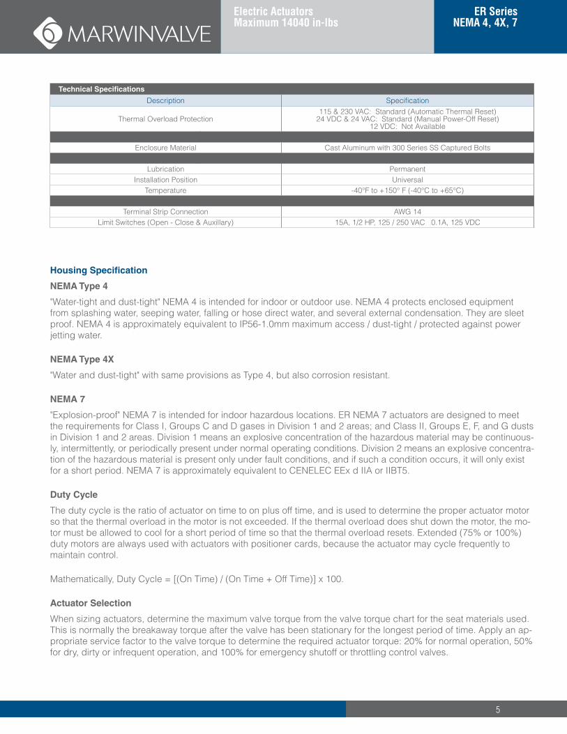
Technical Specifications
Description Specification
Thermal Overload Protection115 & 230 VAC: Standard (Automatic Thermal Reset)
24 VDC & 24 VAC: Standard (Manual Power-Off Reset)12 VDC: Not Available
Enclosure Material Cast Aluminum with 300 Series SS Captured Bolts
Lubrication PermanentInstallation Position Universal
Temperature -40°F to +150° F (-40°C to +65°C)
Terminal Strip Connection AWG 14Limit Switches (Open - Close & Auxillary) 15A, 1/2 HP, 125 / 250 VAC 0.1A, 125 VDC
Housing Specification
NEMA Type 4
"Water-tight and dust-tight" NEMA 4 is intended for indoor or outdoor use. NEMA 4 protects enclosed equipment from splashing water, seeping water, falling or hose direct water, and several external condensation. They are sleet proof. NEMA 4 is approximately equivalent to IP56-1.0mm maximum access / dust-tight / protected against power jetting water.
NEMA Type 4X
"Water and dust-tight" with same provisions as Type 4, but also corrosion resistant.
NEMA 7
"Explosion-proof" NEMA 7 is intended for indoor hazardous locations. ER NEMA 7 actuators are designed to meet the requirements for Class I, Groups C and D gases in Division 1 and 2 areas; and Class II, Groups E, F, and G dusts in Division 1 and 2 areas. Division 1 means an explosive concentration of the hazardous material may be continuous-ly, intermittently, or periodically present under normal operating conditions. Division 2 means an explosive concentra-tion of the hazardous material is present only under fault conditions, and if such a condition occurs, it will only exist for a short period. NEMA 7 is approximately equivalent to CENELEC EEx d IIA or IIBT5.
Duty Cycle
The duty cycle is the ratio of actuator on time to on plus off time, and is used to determine the proper actuator motor so that the thermal overload in the motor is not exceeded. If the thermal overload does shut down the motor, the mo-tor must be allowed to cool for a short period of time so that the thermal overload resets. Extended (75% or 100%) duty motors are always used with actuators with positioner cards, because the actuator may cycle frequently to maintain control.
Mathematically, Duty Cycle = [(On Time) / (On Time + Off Time)] x 100.
Actuator Selection
When sizing actuators, determine the maximum valve torque from the valve torque chart for the seat materials used. This is normally the breakaway torque after the valve has been stationary for the longest period of time. Apply an ap-propriate service factor to the valve torque to determine the required actuator torque: 20% for normal operation, 50% for dry, dirty or infrequent operation, and 100% for emergency shutoff or throttling control valves.
6
ER Series Electric Actuators
Available Options
Note: Option code for ordering schematic in parenthesis
• For ER2 through ER15, the 120 VAC motor duty cycle is indicated by the closing time in the schematic: ER2-5-4-115 for normal (25%) duty cycle; ER2-10-4-115 for extended (75%) duty cycle.
• Auxiliary limit switches in addition to the two standard open and closed switches (S, 2S, 3S, 4S) (2) max. on ER1 to ER4, (4 max) on other sizes)
• Motor Brake, power-off (B)
• Handwheel (HW) (See technical specs for standard, option or not available) and rotating or declutchable
• Heater, Condensation Control (H)
• Heater & Thermostat, Temperature Control (HT) (Heater required at 0°F and below)
• Light Indicator (L)
• Feedback Potentiometer (P) (1 Kohm single turn standard; consult factory for others)
• Speed Control (SC) (ER1 requires separate enclosure; ER2 and ER3 NEMA 4 require the deep base housing)
• Two Wire Control Relay (TW)
• 4-20 mA Positioner (VP) (Includes extended duty motor, and 1 Kohm feedback pot)
Note 1: For ER2 thru ER15 units with 115 VAC motors, the optional 115 VAC extended (75%) duty motor doubles the closing time over the standard (25%) duty motor. Refer to Technical Specifications on pages 3 - 5, and "How to Order ER Series" table on page 7.
Note 2: For units available with both standard and extended duty motors, the extended duty motor is mandatory when supplied with positioner card option.
Note 3: The ER1 with positioner normally uses the ER2 regular housing (Fig. 2 or 4) with an F03 bolt pattern and a 14mm (F05) stem hole. If a 9mm (F03) stem hole is required, the ER1 housing is used with a separate attached enclosure for the positioner.
Note 4: The ER2 and ER3 NEMA 4 with positioner require the deep base housing.
Fail Safe Spring Return Electric Actuators
Consult factory for fail-safe spring return models:
• ES-200: 200 in-lb, light duty, non declutching, VAC only, on-off duty
• AS-400 to AS-1000, 400 to 1000 in-lb, medium duty (approximately 25 cycles a day), non-declutching, VAC only, on-off only
• ASC-400 to ASC-1200, 400 to 1200 in-lb, heavy duty, declutching, VAC and VDC, on-off or modulating
Normal operation by electrical power in both directions, emergency operation by spring to fail position on loss of power.
7
ER Series NEMA 4, 4X, 7
Electric Actuators Maximum 14040 in-lbs
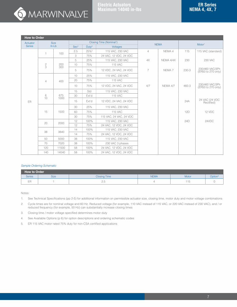
How to Order
Actuator Series
Size In-Lb
Closing Time (Nominal1)NEMA Motor1
Sec2 Duty3 Voltages
ER
1 1002.5 25%5 115 VAC, 230 VAC 4 NEMA 4 115 115 VAC (standard)
3 75% 24 VAC, 12 VDC, 24 VDC
23
200300
5 25% 115 VAC, 230 VAC 4X NEMA 4/4X 230 230 VAC10 75% 115 VAC
5 75% 12 VDC, 24 VAC, 24 VDC 7 NEMA 7 230-3 230/460 VAC/3Ph (ER50 to 270 only)
4 400
10 25% 115 VAC, 230 VAC
20 75% 115 VAC
10 75% 12 VDC, 24 VAC, 24 VDC 4/7 NEMA 4/7 460-3 230/460 VAC/3Ph (ER50 to 270 only)
610
6751000
15 Std 115 VAC, 230 VAC30 Ext'd 115 VAC
15 Ext'd 12 VDC, 24 VAC, 24 VDC 24A 24 VAC (24 VDC Rectified)
15 1500
30 25% 115 VAC, 230 VAC
60 75% 115 VAC 12D 12 VDC
30 75% 115 VAC, 24 VAC, 24 VDC
20 200012 100% 115 VAC, 230 VAC 24D 24VDC12 75% 24 VAC, 12 VDC, 24 VDC
38 384014 100% 115 VAC, 230 VAC
14 75% 24 VAC, 12 VDC, 24 VDC
50 5000 38 100% 115 VAC, 230 VAC
70 7020 38 100% 230 VAC 3 phases120 11500 58 100% 24 VAC, 12 VDC, 24 VDC
140 14040 58 100% 24 VAC, 12 VDC, 24 VDC
Sample Ordering Schematic
How to OrderSeries Size Closing Time NEMA Motor Option4
ER 1 2.5 4 115 0
Notes:
1. See Technical Specifications (pp 2-5) for additional information on permissible actuator size, closing time, motor duty and motor voltage combinations
2. Cycle times are for nominal voltage and 60 Hz. Reduced voltage (for example, 110 VAC instead of 115 VAC, or 220 VAC instead of 230 VAC), and / or reduced frequency (for example, 50 Hz) can substantially increase closing times
3. Closing time / motor voltage specified determines motor duty
4. See Available Options (p 6) for option descriptions and ordering schematic codes
5. ER 115 VAC motor rated 75% duty for non-CSA certified applications
8
ER Series Electric Actuators
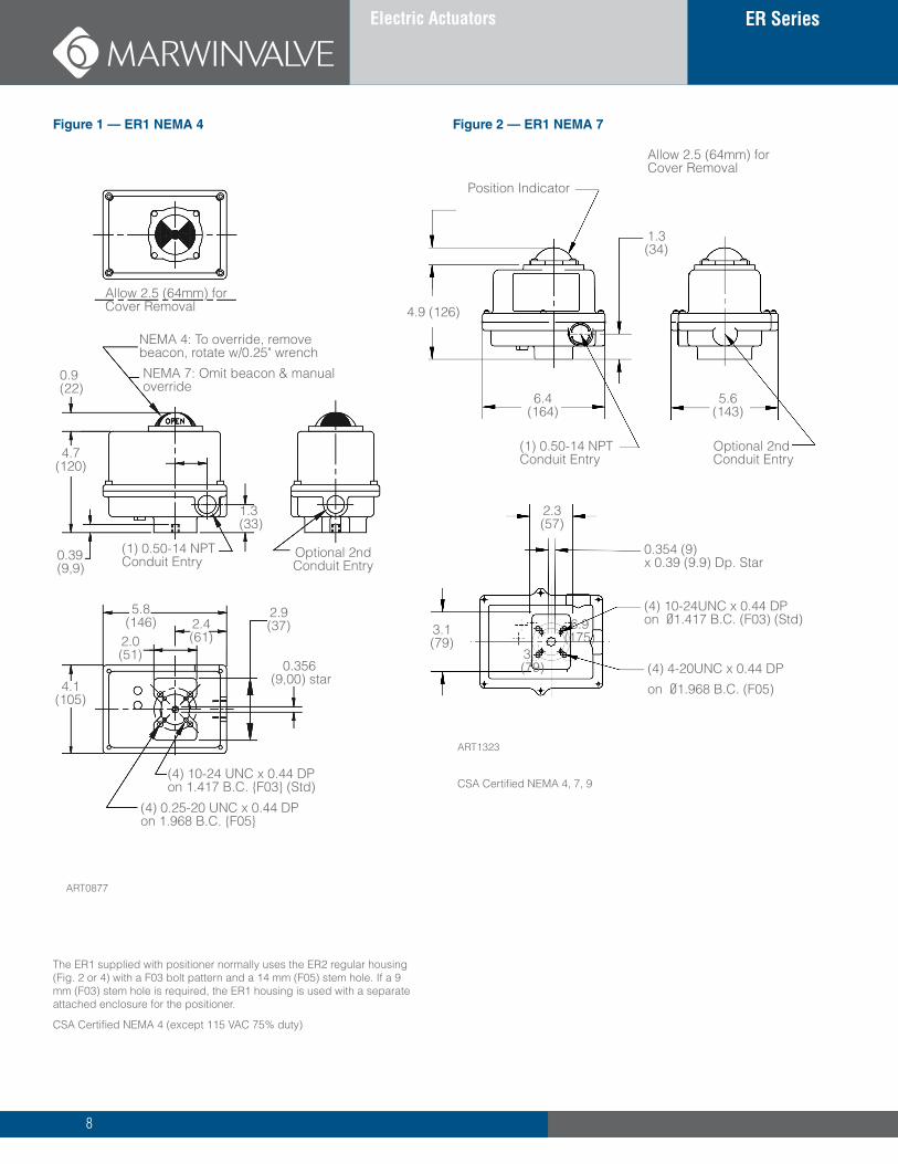
Allow 2.5 (64mm) for Cover Removal
The ER1 supplied with positioner normally uses the ER2 regular housing (Fig. 2 or 4) with a F03 bolt pattern and a 14 mm (F05) stem hole. If a 9 mm (F03) stem hole is required, the ER1 housing is used with a separate attached enclosure for the positioner.
CSA Certified NEMA 4 (except 115 VAC 75% duty)
CSA Certified NEMA 4, 7, 9
Figure 1 — ER1 NEMA 4 Figure 2 — ER1 NEMA 7
NEMA 4: To override, remove beacon, rotate w/0.25" wrench
NEMA 7: Omit beacon & manual override
0.9 (22)
4.7 (120)
0.39 (9,9)
1.3 (33)
(1) 0.50-14 NPT Conduit Entry
4.1 (105)
0.356 (9,00) star
(4) 10-24 UNC x 0.44 DP on 1.417 B.C. {F03} (Std)
(4) 0.25-20 UNC x 0.44 DP on 1.968 B.C. {F05}
2.4 (61)
Optional 2nd Conduit Entry
Allow 2.5 (64mm) for Cover Removal
6.4 (164)
4.9 (126)
3.1 (79)
Optional 2nd Conduit Entry
1.3 (34)
2.3 (57)
5.6 (143)
(1) 0.50-14 NPT Conduit Entry
0.354 (9) x 0.39 (9.9) Dp. Star
6.9 (175)
3.1 (79)
ART0877
ART1323
2.0 (51)
5.8 (146)
2.9 (37)
Position Indicator
(4) 10-24UNC x 0.44 DP on Ø1.417 B.C. (F03) (Std)
(4) 4-20UNC x 0.44 DP
on Ø1.968 B.C. (F05)
9
ER Series NEMA 4, 4X, 7
Electric Actuators Maximum 14040 in-lbs
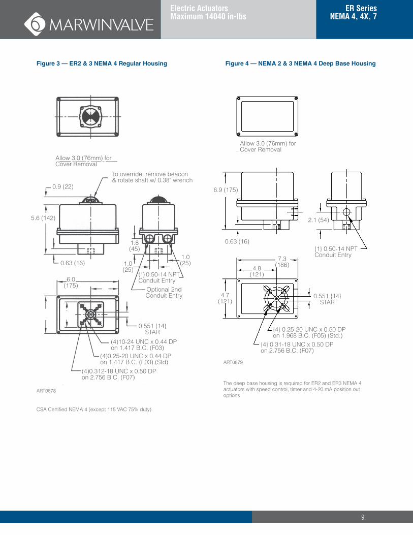
The deep base housing is required for ER2 and ER3 NEMA 4 actuators with speed control, timer and 4-20 mA position out options
Figure 3 — ER2 & 3 NEMA 4 Regular Housing
Allow 3.0 (76mm) for Cover Removal
6.9 (175)
0.63 (16)
2.1 (54)
{1} 0.50-14 NPT Conduit Entry
7.3 (186)4.8
(121)
4.7 (121)
0.551 {14} STAR
{4} 0.25-20 UNC x 0.50 DP on 1.968 B.C. (F05) (Std.)
{4} 0.31-18 UNC x 0.50 DP on 2.756 B.C. (F07)
ART0879
Figure 4 — NEMA 2 & 3 NEMA 4 Deep Base Housing
CSA Certified NEMA 4 (except 115 VAC 75% duty)
Allow 3.0 (76mm) for Cover Removal
0.9 (22)
5.6 (142)
(1) 0.50-14 NPT Conduit Entry
0.551 {14} STAR
(4)0.312-18 UNC x 0.50 DP on 2.756 B.C. (F07)
ART0878
To override, remove beacon & rotate shaft w/ 0.38" wrench
0.63 (16)
1.8 (45)
1.0 (25)
1.0 (25)
Optional 2nd Conduit Entry
6.0 (175)
(4)10-24 UNC x 0.44 DP on 1.417 B.C. (F03)
(4)0.25-20 UNC x 0.44 DP on 1.417 B.C. (F03) (Std)
10
ER Series Electric Actuators
Note: Allow 4.0" (102mm) for cover removal
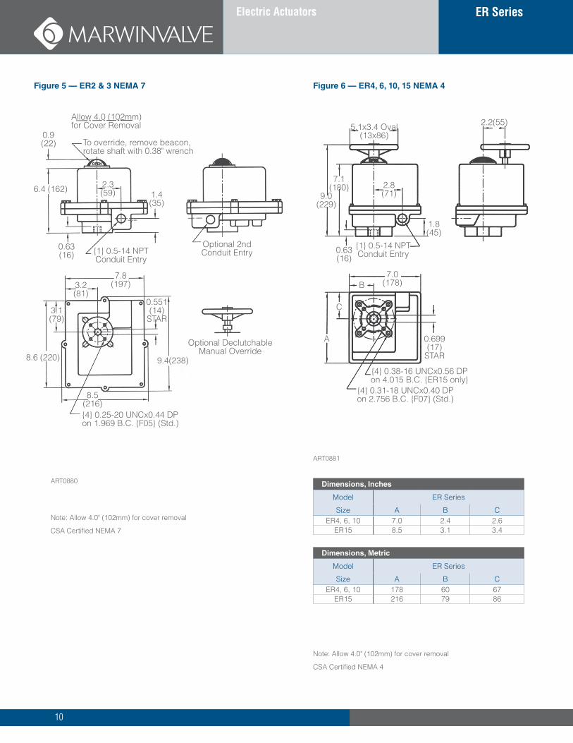
CSA Certified NEMA 4
Figure 6 — ER4, 6, 10, 15 NEMA 4
ART0881
5.1x3.4 Oval (13x86)
7.1 (180)
9.0 (229)
2.8 (71)
0.63 (16)
1.8 (45)
{1} 0.5-14 NPT Conduit Entry
2.2(55)
7.0 (178)
0.699 (17)
STAR
C
A
B
{4} 0.38-16 UNCx0.56 DP on 4.015 B.C. {ER15 only}
{4} 0.31-18 UNCx0.40 DP on 2.756 B.C. {F07} (Std.)
Dimensions, Inches
Model ER Series
Size A B CER4, 6, 10 7.0 2.4 2.6
ER15 8.5 3.1 3.4
Dimensions, Metric
Model ER Series
Size A B CER4, 6, 10 178 60 67
ER15 216 79 86
Note: Allow 4.0" (102mm) for cover removal
CSA Certified NEMA 7
Figure 5 — ER2 & 3 NEMA 7
To override, remove beacon, rotate shaft with 0.38" wrench
Allow 4.0 (102mm) for Cover Removal
{4} 0.25-20 UNCx0.44 DP on 1.969 B.C. {F05} (Std.)
8.5 (216)
8.6 (220) 9.4(238)
7.8 (197)3.2
(81)
3.1 (79)
0.551 (14)
STAR
Optional Declutchable Manual Override
Optional 2nd Conduit Entry
0.9 (22)
6.4 (162)
0.63 (16)
1.4 (35)
{1} 0.5-14 NPT Conduit Entry
ART0880
2.3 (59)
11
ER Series NEMA 4, 4X, 7
Electric Actuators Maximum 14040 in-lbs
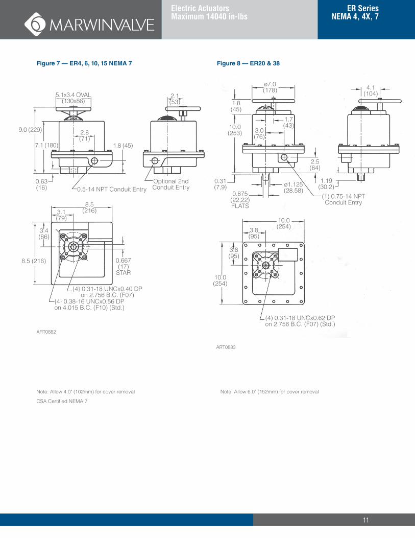
Note: Allow 6.0" (152mm) for cover removal
Figure 8 — ER20 & 38
ART0883
ø7.0 (178)
1.8 (45)
10.0 (253)
0.31 (7,9)
0.875 (22,22) FLATS
ø1.125 (28,58)
(1) 0.75-14 NPT Conduit Entry
2.5 (64)
1.7 (43)
3.0 (76)
4.1 (104)
1.19 (30,2)
10.0 (254) 3.8
(95)
3.8 (95)
10.0 (254)
(4) 0.31-18 UNCx0.62 DP on 2.756 B.C. (F07) (Std.)
Note: Allow 4.0" (102mm) for cover removal
CSA Certified NEMA 7
Figure 7 — ER4, 6, 10, 15 NEMA 7
ART0882
8.5 (216)
3.4 (86)
3.1 (79)
8.5 (216)
0.667 (17)
STAR
{4} 0.31-18 UNCx0.40 DP on 2.756 B.C. (F07)
{4} 0.38-16 UNCx0.56 DP on 4.015 B.C. (F10) (Std.)
0.5-14 NPT Conduit Entry0.63 (16)
7.1 (180)
9.0 (229)
5.1x3.4 OVAL (130x86)
2.8 (71)
1.8 (45)
2.1 (53)
Optional 2nd Conduit Entry
12
ER Series Electric Actuators
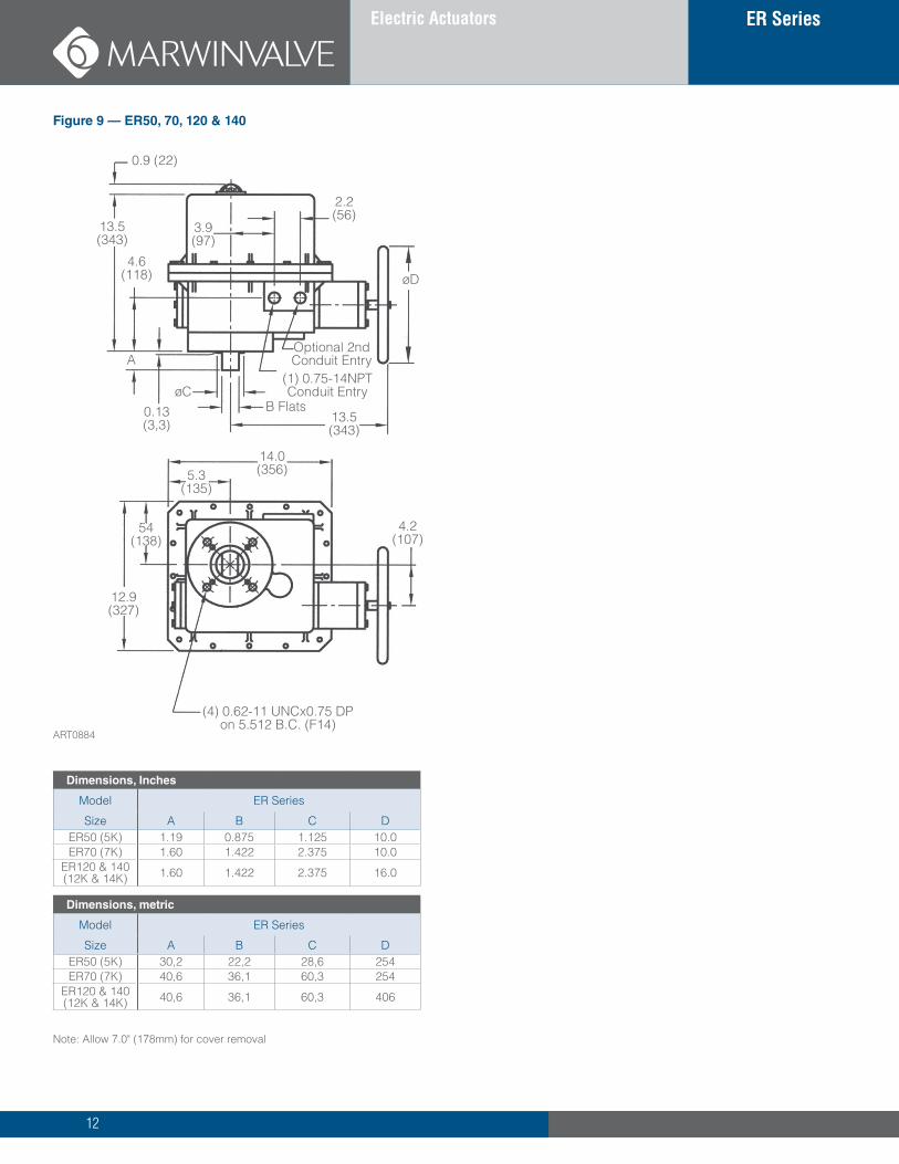
Note: Allow 7.0" (178mm) for cover removal
Figure 9 — ER50, 70, 120 & 140
0.9 (22)
13.5 (343)
4.6 (118)
A
0.13 (3,3)
øC B Flats
13.5 (343)
Optional 2nd Conduit Entry
(1) 0.75-14NPT Conduit Entry
øD
3.9 (97)
2.2 (56)
14.0 (356) 5.3
(135)
54 (138)
12.9 (327)
4.2 (107)
(4) 0.62-11 UNCx0.75 DP on 5.512 B.C. (F14)
Dimensions, Inches
Model ER Series
Size A B C DER50 (5K) 1.19 0.875 1.125 10.0ER70 (7K) 1.60 1.422 2.375 10.0
ER120 & 140 (12K & 14K) 1.60 1.422 2.375 16.0
Dimensions, metric
Model ER Series
Size A B C DER50 (5K) 30,2 22,2 28,6 254ER70 (7K) 40,6 36,1 60,3 254
ER120 & 140 (12K & 14K) 40,6 36,1 60,3 406
ART0884
13
ER Series Electric Actuators
ERSeries/0718
Marwin ValveA Division of Richards Industries, 3170 Wasson Road, Cincinnati, OH 45209toll free. 800.543.7311, local. 513.533.5600, fax. 513.871.0105www.marwinvalve.com
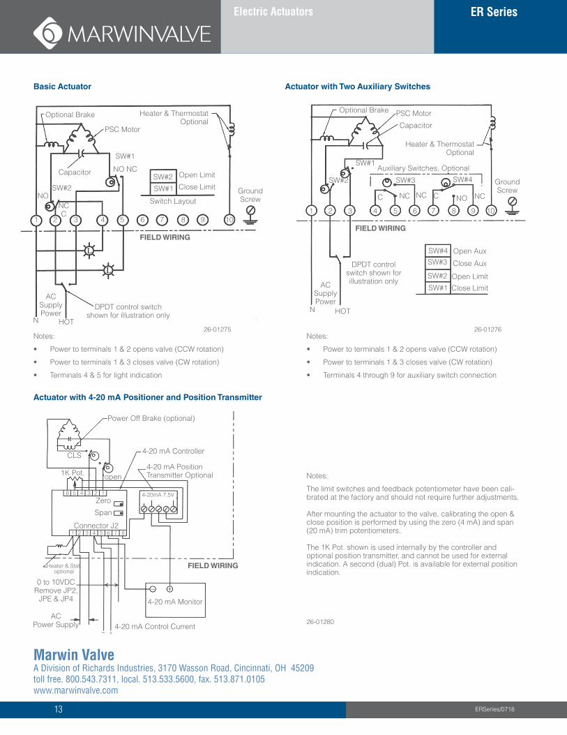
Basic Actuator Actuator with Two Auxiliary Switches
Optional Brake Heater & Thermostat Optional
Open Limit
Close LimitSW#1
SW#2
PSC Motor
SW#1
NO NCCapacitor
Switch LayoutGround Screw
1 2 3 4 5 6 7 8 9 10
FIELD WIRING
DPDT control switch shown for illustration only
HOTN
AC Supply Power
NC C
SW#2NO
26-01275Notes:
• Power to terminals 1 & 2 opens valve (CCW rotation)
• Power to terminals 1 & 3 closes valve (CW rotation)
• Terminals 4 & 5 for light indication
Notes:
• Power to terminals 1 & 2 opens valve (CCW rotation)
• Power to terminals 1 & 3 closes valve (CW rotation)
• Terminals 4 through 9 for auxiliary switch connection
DPDT control switch shown for illustration only
HOTN
AC Supply Power
SW#1
SW#2
SW#3SW#4
Close Limit
Open Limit
Open Aux
Close Aux
FIELD WIRING
1 2 3 4 5 6 7 8 9 10
Optional Brake PSC Motor
Capacitor
Heater & Thermostat Optional
Auxiliary Switches, Optional
SW#3 SW#4 Ground Screw
SW#2
SW#1
C NC NC C NO NC
26-01276
Actuator with 4-20 mA Positioner and Position Transmitter
Notes:
The limit switches and feedback potentiometer have been cali-brated at the factory and should not require further adjustments. After mounting the actuator to the valve, calibrating the open & close position is performed by using the zero (4 mA) and span (20 mA) trim potentiometers. The 1K Pot. shown is used internally by the controller and optional position transmitter, and cannot be used for external indication. A second (dual) Pot. is available for external position indication.
26-01280
Power Off Brake (optional)
4-20 mA Controller
4-20 mA Position Transmitter Optional
FIELD WIRING
4-20 mA Monitor
4-20 mA Control CurrentAC
Power Supply
0 to 10VDC Remove JP2,
JPE & JP4
Heater & Stat. optional
Connector J2
Zero
Span
1K Pot.
CLS
open
4-20mA 7.5V
1 2 3 4 5 6 7 8
123456