Embed Size (px)
Citation preview
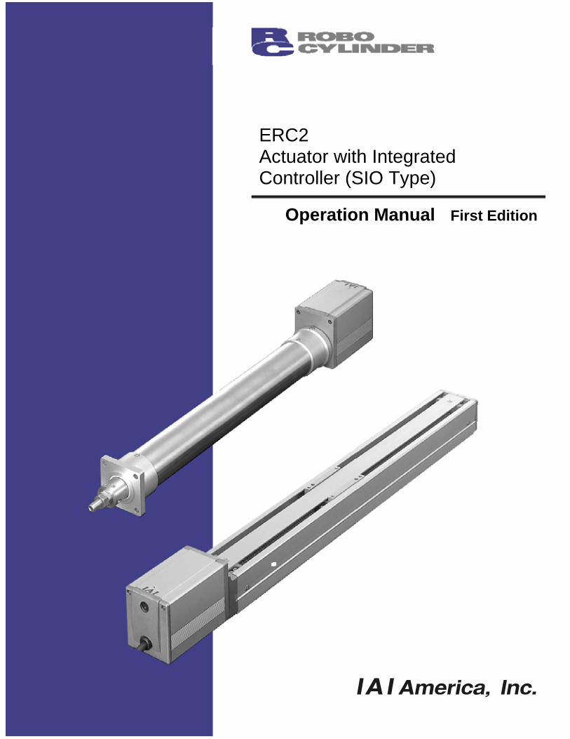
Operation Manual First Edition
ERC2 Actuator with Integrated Controller (SIO Type)
CAUTION
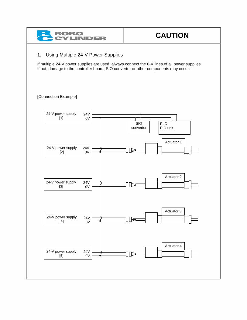
1. Using Multiple 24-V Power Supplies If multiple 24-V power supplies are used, always connect the 0-V lines of all power supplies. If not, damage to the controller board, SIO converter or other components may occur. [Connection Example]
24V0V
24V0V
24V0V
24V0V
24V0V
24-V power supply [1]
24-V power supply [2]
24-V power supply [3]
24-V power supply [4]
24-V power supply [5]
SIO converter
PLC PIO unit
Actuator 1
Actuator 2
Actuator 3
Actuator 4

CAUTION
2. Basic Parameter Settings When the power is turned on for the first time, at least the parameters explained below must be set in accordance with your specific application. Remember to always set these parameters properly, because improper settings will prevent the product from operating correctly. For details on how to set these parameters, refer to “parameter settings” of the PC software or teaching pendant.
CAUTION
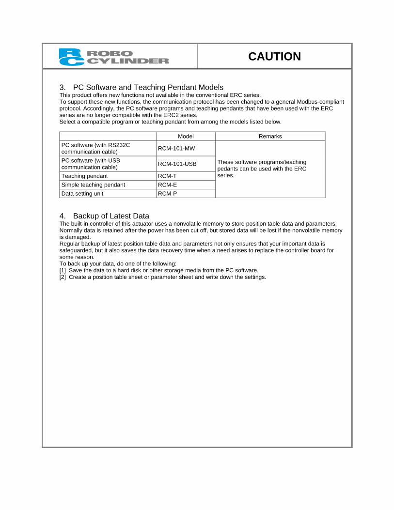
3. PC Software and Teaching Pendant Models This product offers new functions not available in the conventional ERC series. To support these new functions, the communication protocol has been changed to a general Modbus-compliant protocol. Accordingly, the PC software programs and teaching pendants that have been used with the ERC series are no longer compatible with the ERC2 series. Select a compatible program or teaching pendant from among the models listed below.
Model Remarks
PC software (with RS232C communication cable) RCM-101-MW
PC software (with USB communication cable) RCM-101-USB
Teaching pendant RCM-T Simple teaching pendant RCM-E Data setting unit RCM-P
These software programs/teaching pedants can be used with the ERC series.
4. Backup of Latest Data The built-in controller of this actuator uses a nonvolatile memory to store position table data and parameters. Normally data is retained after the power has been cut off, but stored data will be lost if the nonvolatile memory is damaged. Regular backup of latest position table data and parameters not only ensures that your important data is safeguarded, but it also saves the data recovery time when a need arises to replace the controller board for some reason. To back up your data, do one of the following: [1] Save the data to a hard disk or other storage media from the PC software. [2] Create a position table sheet or parameter sheet and write down the settings.

Safety Precautions (Please read before using the product.)
Before installing, operating, maintaining or inspecting this product, please peruse this operating manual as well as the operating manuals and other related documentations for all equipment and peripheral devices connected to this product in order to ensure the correct use of this product and connected equipment/devices. Those performing installation, operation, maintenance and inspection of the product must have sufficient knowledge of the relevant equipment and their safety. The precautions provided below are designed to help you use the product safely and avoid bodily injury and/or property damage. In this operating manual, safety precautions are classified as “Danger,” “Warning,” “Caution” and “Note,” according to the degree of risk.
Danger Failure to observe the instruction will result in an imminent danger leading to death or serious injury.
Warning Failure to observe the instruction may result in death or serious injury.
Caution Failure to observe the instruction may result in injury or property damage.
Note The user should take heed of this information to ensure the proper use of the product, although failure to do so will not result in injury.
It should be noted that the instructions under the Caution and Note headings may also lead to serious
consequences, if unheeded, depending on the situation. All instructions contained herein provide vital information for ensuring safety. Please read the contents carefully and handle the product with due caution. Please keep this operating manual in a convenient place for quick reference whenever needed, and also make sure that the manual will get to the end-user.
Danger [General]
Do not use this product for the following applications: 1. Medical equipment used to maintain, control or otherwise affect human life or physical health 2. Mechanisms and machinery designed for the purpose of moving or transporting people 3. Important safety parts of machinery
This product has not been planned or designed for applications requiring high levels of safety. Use of this product in such applications may jeopardize the safety of human life. The warranty covers only the product as it is delivered.
[Installation]
Do not use this product in a place exposed to ignitable, inflammable or explosive substances. The product may ignite, burn or explode.
When installing the product, be sure to securely support and affix it (including the work). Failure to do so may cause the product to tip over, drop or malfunction, resulting in injury.
Avoid using the product in a place where it may come in contact with water or oil droplets. Never cut and/or reconnect the cables supplied with the product for the purpose of extending or shortening the
cable length. Doing so may result in fire. [Operation]
Do not enter the machine’s range of operation while the product is operating or standing by. The actuator may move suddenly, causing injury.
Do not pour water onto the product. Spraying water over the product, washing it with water or using it in water may cause the product to malfunction, resulting in injury, electric shock, fire, etc.
[Maintenance, Inspection, Repair]
Never modify the product. Unauthorized modification may cause the product to malfunction, resulting in injury, electric shock, fire, etc.
Do not disassemble and reassemble the components relating to the basic structure of the product or its performance and function. Doing so may result in injury, electric shock, fire, etc.
Warning [General]
Do not use the product outside the specifications. Using the product outside the specifications may cause it to fail, stop functioning or sustain damage. It may also significantly reduce the service life of the product. In particular, observe the maximum loading capacity and speed.
[Installation]
If the machine will stop in the case of system problem such as emergency stop or power failure, design a safety circuit or other device that will prevent equipment damage or injury.
Be sure to provide Class D grounding for the actuator (formerly Class 3 grounding: grounding resistance at 100 Ω or less). Leakage current may cause electric shock or malfunction.
Before supplying power to and operating the product, always check the operation area of the equipment to ensure safety. Supplying power to the product carelessly may cause electric shock or injury due to contact with the moving parts.
Wire the product correctly by referring to this manual. Securely connect the cables and connectors so that they will not be disconnected or become loose. Failure to do so may cause the product to malfunction or cause fire.
[Operation]
Do not touch the terminal block or various switches while the power is supplied to the product. Electric shock or malfunction may result.
Before operating the moving parts of the product by hand (for the purpose of manual positioning, etc.), confirm that the servo is turned off (using the teaching pendant). Failure to observe this instruction may result in injury.
Do not scratch the cables. Scratching, forcibly bending, pulling, winding, crushing with heavy object or pinching a cable may cause it to leak current or lose continuity, resulting in fire, electric shock, malfunction, etc.
Turn off the power to the product in the event of power failure. Failure to do so may cause the product to suddenly start moving when the power is restored, thus resulting in injury or product damage.
If the product is generating heat, smoke or a strange smell, turn off the power immediately. Continuing to use the product may result in product damage or fire.
If noise or abnormally high vibration is detected, stop the operation immediately. Continuing to use the product may result in product damage, malfunction due to damage, runaway machine, etc.
If any of the product’s protective functions (alarms) has actuated, turn off the power immediately. Continuing to use the product may result in injury due to product malfunction, or cause product breakdown or damage. After the power has been cut off, identify and remove the cause of the problem, and then reconnect the power.
If the LEDs on the product do not illuminate after turning on the power, turn off the power immediately. Do not step on the product, use it as a footstool or place any object on it. You may slip and fall or the product may
tip over or drop, resulting in injury. Malfunction, runaway product, etc., may also result due to product breakdown or damage.
[Maintenance, Inspection, Repair]
Before commencing maintenance/inspection, servicing, replacement or any other work on the product, be sure to completely cut off the power supply to the product. Also take heed of the following precautions: 1. Put up a sign bearing “WORK IN PROGRESS. DO NOT TURN ON POWER” or other warning statement to
that effect, to prevent a bystander from accidentally turning on the power. 2. If multiple operators work together to perform maintenance/inspection work, the operators should always give
verbal cues to one another to ensure safety before turning on/off the power or moving any axis. [Disposal]
Do not throw the product into flames. The product may explode or toxic gases may generate.
Caution [Installation]
Do not use the product in a place exposed to direct sunlight (UV ray), salt, high humidity or atmosphere containing organic solvent or phosphate-ester machine oil. The product may lose its function over a short period of time or exhibit a sudden drop in performance, or its service life may be significantly reduced. The product may also malfunction if used in these environments.
Do not use the product in an ambience where it may come in contact with corrosive gases (sulfuric acid, hydrochloric acid, etc.). The product may lose its strength due to rust.
Provide sufficient shielding measures if the product is used in any of the following places. If proper measures are not taken, the product may malfunction: 1. Place where large current or strong magnetic field generates 2. Place where arc discharge occurs due to welding work, etc. 3. Place where noise generates due to electrostatic, etc. 4. Place where the product may come in contact with radiation
Do not install the product in a place subject to large vibration or impact. Doing so may result in the malfunctioning of the product.
Provide an emergency stop device in an easily accessible position so the device can be immediately actuated should danger occur during operation. Failure to do so may result in injury.
Provide sufficient maintenance space when installing the product. Routine inspection and maintenance cannot be performed without sufficient space, in which case your equipment may stop or the product may break down, or injury may result.
When transporting or installing the product, support the product using a lift or suspension equipment or carry it with multiple operators working together, and exercise due caution to ensure safety.
When installing the product, do not hold the moving parts or cables of the product. Doing so may result in injury. Use IAI’s genuine products for the component units such as the actuator, relay cables and teaching pendant. The brake mechanism of the product is designed to prevent the slider from dropping in a vertical application when
the power is turned off. Do not use it as a safety brake (means for reducing the speed) or for any other purpose. When installing, adjusting or carrying out any other work on the actuator, put up a sign bearing “WORK IN
PROGRESS. DO NOT TURN ON POWER” or other warning statement to that effect, to prevent the product from being powered on accidentally. If the power is turned on accidentally, injury may result due to electric shock or sudden movement of the actuator.
[Operation]
Turn on the power to individual equipment one by one, starting from the equipment at the highest level in the system hierarchy. Failure to do so may cause the product to start suddenly, resulting in injury or product damage.
Do not insert a finger or object in the openings in the product. It may cause fire, electric shock or injury. [Maintenance, Inspection, Repair]
Wear protective goggles when applying grease to the actuator. Failure to do so may result in eye inflammation due to spattered grease.
Note [Installation]
If the product is used in a vertical setup, be sure to use the vertical specification (with brake). Protection covers or other guards must be provided for the moving parts of the equipment to avoid direct contact
with the operators. Do not configure a control circuit that will cause the work to drop in case of power failure. Configure a control
circuit that will prevent the table or work from dropping when the power to the machine is cut off or an emergency stop is actuated.
The following conditions must be met in order to improve the straightness of the table movement and ensure the smooth movement of the ball screw and linear guides: 1. Flatness of the mounting surface must be within 0.05 mm. 2. The mounting surface area must be large enough to ensure the rigidity of the actuator.
[Installation, Operation, Maintenance]
When handling the product, wear protective gloves, protective goggles, safety shoes or other necessary gear to ensure safety.
[Maintenance, Inspection, Repair]
Use the specified ball screw grease for maintenance. In particular, be careful not to mix fluorine grease with lithium grease, because it may damage the mechanism due to poor lubrication, increased resistance, and so on.
[Disposal]
When the product becomes no longer usable or necessary, dispose of it properly as an industrial waste.
Others
IAI shall not be liable whatsoever for any loss or damage arising from a failure to observe the items specified in “Safety Precautions.”
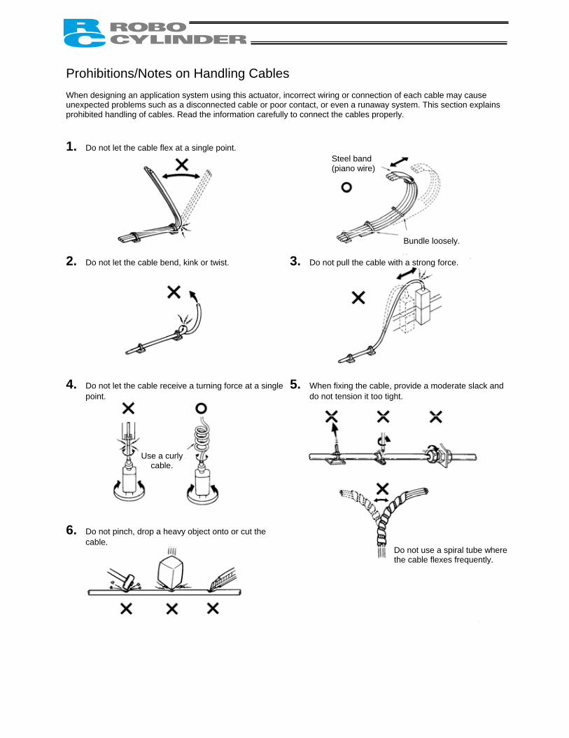
Prohibitions/Notes on Handling Cables When designing an application system using this actuator, incorrect wiring or connection of each cable may cause unexpected problems such as a disconnected cable or poor contact, or even a runaway system. This section explains prohibited handling of cables. Read the information carefully to connect the cables properly.
1. Do not let the cable flex at a single point.
2. Do not let the cable bend, kink or twist.
3. Do not pull the cable with a strong force.
4. Do not let the cable receive a turning force at a single point.
6. Do not pinch, drop a heavy object onto or cut the
cable.
5. When fixing the cable, provide a moderate slack and do not tension it too tight.
Steel band (piano wire)
Bundle loosely.
Use a curly cable.
Do not use a spiral tube where the cable flexes frequently.
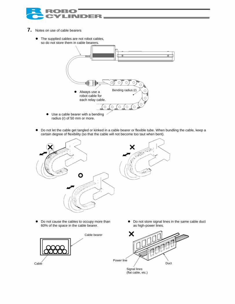
7. Notes on use of cable bearers
Cable
Cable bearer
Always use a robot cable for each relay cable.
Bending radius (r)
Use a cable bearer with a bending radius (r) of 50 mm or more.
Power line
Signal lines (flat cable, etc.)
Duct
The supplied cables are not robot cables, so do not store them in cable bearers.
Do not let the cable get tangled or kinked in a cable bearer or flexible tube. When bundling the cable, keep a certain degree of flexibility (so that the cable will not become too taut when bent).
Do not cause the cables to occupy more than 60% of the space in the cable bearer.
Do not store signal lines in the same cable duct as high-power lines.
Table of Contents
1. Overview ................................................................................................................................................ 1 1.1 Introduction ................................................................................................................................................. 1 1.2 Key Features and Functions ....................................................................................................................... 2 1.3 Differences from Air Cylinder Control.......................................................................................................... 3 1.4 Meaning of the Model Name....................................................................................................................... 5 1.5 Specifications.............................................................................................................................................. 6
1.5.1 Correlation Diagrams of Speed and Load Capacity – Slider Type ................................................ 7 1.5.2 Correlation Diagrams of Speed and Load Capacity – Rod Type................................................... 8
1.6 Warranty Period and Scope of Warranty................................................................................................... 10 1.7 Transportation and Handling..................................................................................................................... 11
1.7.1 Handling before Unpacking......................................................................................................... 11 1.7.2 Handling after Unpacking............................................................................................................ 11
1.8 Installation Environment and Noise Elimination ........................................................................................ 12 1.8.1 Installation Environment.............................................................................................................. 12 1.8.2 Storage Environment .................................................................................................................. 12 1.8.3 Power Supply.............................................................................................................................. 13 1.8.4 Noise Elimination ........................................................................................................................ 13
1.9 Cabling...................................................................................................................................................... 15
2. Installation............................................................................................................................................ 17 2.1 Name of Each Part.................................................................................................................................... 17
2.1.1 Slider Type (SA6C/SA7C)........................................................................................................... 17 2.1.2 Rod Type (RA6C/RA7C) ............................................................................................................. 17 2.1.3 (1) Rod Type with a Single Guide (RGS6C/RGS7C) .................................................................. 18 (2) Rod Type with Double Guides (RGD6C/RGD7C).................................................................. 18
2.2 Installation................................................................................................................................................. 19 2.2.1 Slider Type.................................................................................................................................. 19 2.2.2 Rod Type .................................................................................................................................... 20 2.2.3 Installing the Load....................................................................................................................... 23
3. Electrical Specifications ....................................................................................................................... 25 3.1 Controller .................................................................................................................................................. 25 3.2 Input/Output Interfaces ............................................................................................................................. 26 3.3 SIO Converter (Optional) .......................................................................................................................... 27
4. Wiring................................................................................................................................................... 29 4.1 Basic Structure.......................................................................................................................................... 29
4.1.1 Linking Multiple Axes .................................................................................................................. 31 4.1.2 Address Assignment ................................................................................................................... 32
4.2 Configuration Using a Gateway Unit ......................................................................................................... 33 4.2.1 SIO Communication Connection Using a Relay Terminal Block ................................................. 33 4.2.2 SIO Communication Connection Using a 4-Way Junction .......................................................... 34 4.2.3 Connecting an Emergency Stop Circuit, Etc. .............................................................................. 35
4.3 Relay Cable .............................................................................................................................................. 36
5. Explanation of Operating Functions..................................................................................................... 37 5.1 Description of Position Table..................................................................................................................... 38
5.1.1 Relationship of Push Force at Standstill and Current-Limiting Value .......................................... 42 5.2 Data Set in the Numerical Specification Mode .......................................................................................... 44 5.3 Explanation of Functions........................................................................................................................... 44
5.3.1 Control Signals and Control Data ............................................................................................... 46 5.3.2 Timings after Power On .............................................................................................................. 52 5.3.3 Home Return Operation.............................................................................................................. 54 5.3.4 Positioning Operation ................................................................................................................. 56 5.3.5 Push & Hold Operation ............................................................................................................... 60 5.3.6 Pause ......................................................................................................................................... 64 5.3.7 Speed Change during Movement ............................................................................................... 65 5.3.8 Operation at Different Acceleration and Deceleration ................................................................. 67 5.3.9 Zone Signal................................................................................................................................. 68 5.3.10 Pitch Feed by Incremental Specification ..................................................................................... 69 5.3.11 Power-Saving Mode at Standby Positions .................................................................................. 73
6. Parameter Settings .............................................................................................................................. 74 6.1 Parameter Table........................................................................................................................................ 74 6.2 Detailed Explanation of Parameters.......................................................................................................... 75
6.2.1 Parameters Relating to the Actuator Stroke Range .................................................................... 75 6.2.2 Parameters Relating to the Actuator Operating Characteristics.................................................. 77 6.2.3 Parameters Relating to the External Interface ............................................................................ 81 6.2.4 Servo Gain Adjustment ............................................................................................................... 83
7. Troubleshooting ................................................................................................................................... 85 7.1 Action to Be Taken upon Occurrence of Problem ..................................................................................... 85 7.2 Alarm Level Classification......................................................................................................................... 86
7.2.1 How to Reset Alarms .................................................................................................................. 86 7.3 Alarm Description and Cause/Action ........................................................................................................ 87 7.4 Messages Displayed during Operation Using the Teaching Pendant or PC Software .............................. 92 7.5 Specific Problems ..................................................................................................................................... 94
8. Maintenance and Inspection................................................................................................................ 96 8.1 Inspection Items and Timings ................................................................................................................... 96 8.2 Visual Inspection of Appearance............................................................................................................... 96 8.3 Cleaning.................................................................................................................................................... 96 8.4 Internal Check (Slider Type) ..................................................................................................................... 97 8.5 Internal Cleaning (Slider Type).................................................................................................................. 98 8.6 Greasing the Guide (Slider Type).............................................................................................................. 98 8.7 Greasing the Ball Screw (Slider Type) .................................................................................................... 100 8.8 Greasing the Rod Slide Surface ............................................................................................................. 101 8.9 Motor Replacement Procedure ............................................................................................................... 102
9. Operation Examples .......................................................................................................................... 104
1. Overview 1.1 Introduction Thank you for purchasing the Easy All-in-One ROBO Cylinder (hereinafter referred to as “ERC2-SE”). This product retains all benefits of the conventional ERC series, while incorporating new features that provide greater convenience and enhanced safety to the users. Among the ERC2 Series actuators, this product can be operated via serial communication in the position number specification mode or the numerical specification mode. The following two communication patterns are supported by serial communication systems: [1] Communicate with a host PLC, etc., via a gateway unit in various field network environments (DeviceNet, CC-Link
and Profibus). [2] Communicate serially with a PC or PLC via a SIO converter based on the RS-232C protocol. Please read this manual carefully and handle the product with utmost care while ensuring its correct operation. Keep this manual in a convenient place so the relevant sections can be referenced readily when necessary. When starting your system or in the event of failure, also refer to the operation manuals for the teaching pendant, PC software and other components you are using with this product.
This manual does not cover all possible operations other than normal operations, or unexpected events such as complex signal changes resulting from operating the product at critical timings. Accordingly, think of any item not specifically mentioned in this manual as “prohibited.”
* We have made every effort to ensure accuracy of the information provided in this manual. Should you find an
error, however, or if you have any comment, please contact IAI. Keep this manual in a convenient place so it can be referenced readily when necessary.
1
1.2 Key Features and Functions (1) Input/output of control signals by means of RS485 serial communication (conforming to the Modbus
protocol) (2) 64 positioning points (3) Variable zone output boundaries
Before, zone output boundaries were set by parameters and therefore fixed. For greater convenience, this product permits setting of zone output boundaries in the position table. (This function is available only in the position number specification mode.) Set desired boundaries to prevent contact with peripheral equipment, shorten the tact time, etc.
(4) Different acceleration and deceleration settings (This function is available only in the position number
specification mode.) Acceleration and deceleration can be set differently in the position table. In situations where shock and vibration upon stopping must be minimized depending on the material or shape of the load, you can decrease only the deceleration to allow the actuator to stop along a gradual deceleration curve.
(5) Limitation of moving speed during adjustment by trial operation
During adjustment by trial operation, the moving speed of the actuator can be limited to ensure safety. (6) Power-saving measure
In general, pulse motors generate greater holding current than AC servo motors in a standstill state. Accordingly, we provide a power-saving mode to conserve electricity in situations where the actuator stands by for a long period.
2
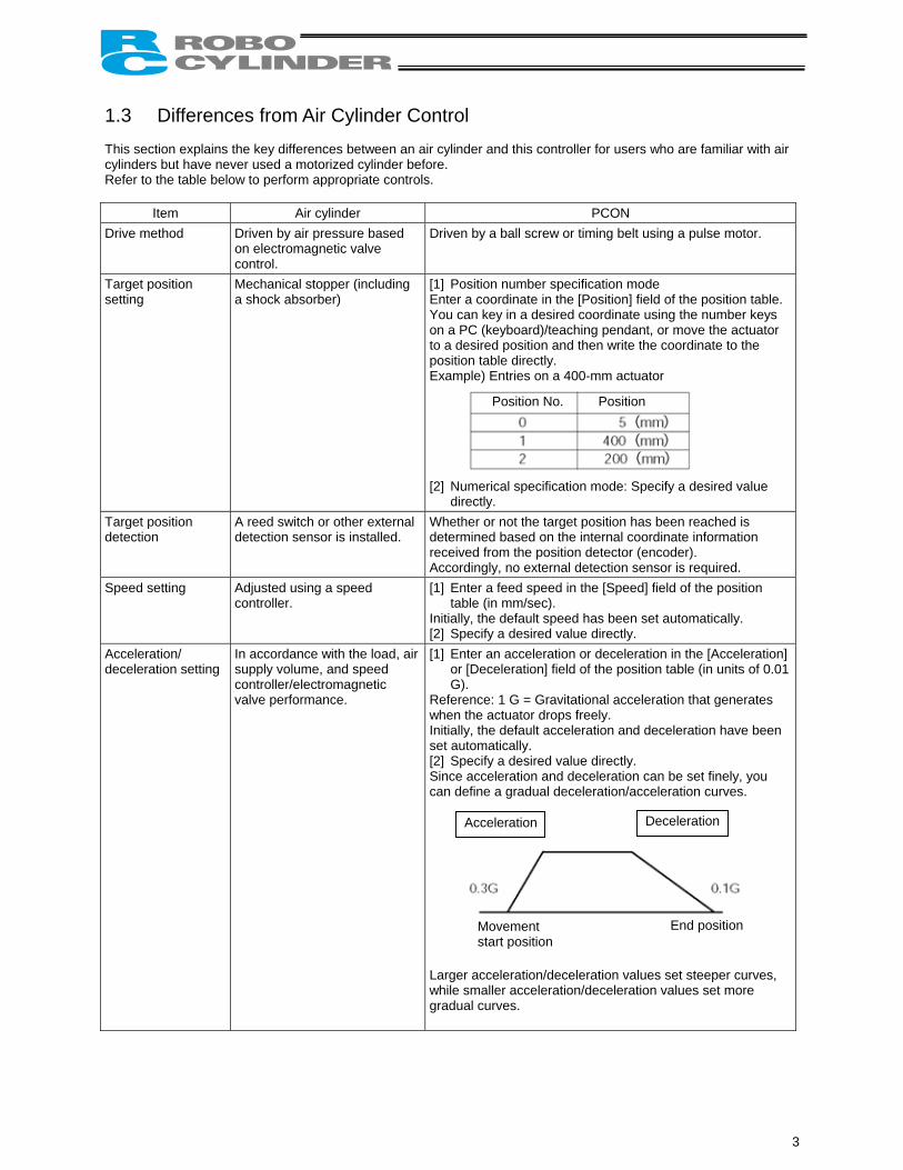
1.3 Differences from Air Cylinder Control This section explains the key differences between an air cylinder and this controller for users who are familiar with air cylinders but have never used a motorized cylinder before. Refer to the table below to perform appropriate controls.
Item Air cylinder PCON Drive method Driven by air pressure based
on electromagnetic valve control.
Driven by a ball screw or timing belt using a pulse motor.
Target position setting
Mechanical stopper (including a shock absorber)
[1] Position number specification mode Enter a coordinate in the [Position] field of the position table. You can key in a desired coordinate using the number keys on a PC (keyboard)/teaching pendant, or move the actuator to a desired position and then write the coordinate to the position table directly. Example) Entries on a 400-mm actuator
[2] Numerical specification mode: Specify a desired value
directly. Target position detection
A reed switch or other external detection sensor is installed.
Whether or not the target position has been reached is determined based on the internal coordinate information received from the position detector (encoder). Accordingly, no external detection sensor is required.
Speed setting Adjusted using a speed controller.
[1] Enter a feed speed in the [Speed] field of the position table (in mm/sec).
Initially, the default speed has been set automatically. [2] Specify a desired value directly.
Acceleration/ deceleration setting
In accordance with the load, air supply volume, and speed controller/electromagnetic valve performance.
[1] Enter an acceleration or deceleration in the [Acceleration] or [Deceleration] field of the position table (in units of 0.01 G).
Reference: 1 G = Gravitational acceleration that generates when the actuator drops freely. Initially, the default acceleration and deceleration have been set automatically. [2] Specify a desired value directly. Since acceleration and deceleration can be set finely, you can define a gradual deceleration/acceleration curves.
Larger acceleration/deceleration values set steeper curves, while smaller acceleration/deceleration values set more gradual curves.
Position No. Position
Acceleration Deceleration
Movement start position
End position
3
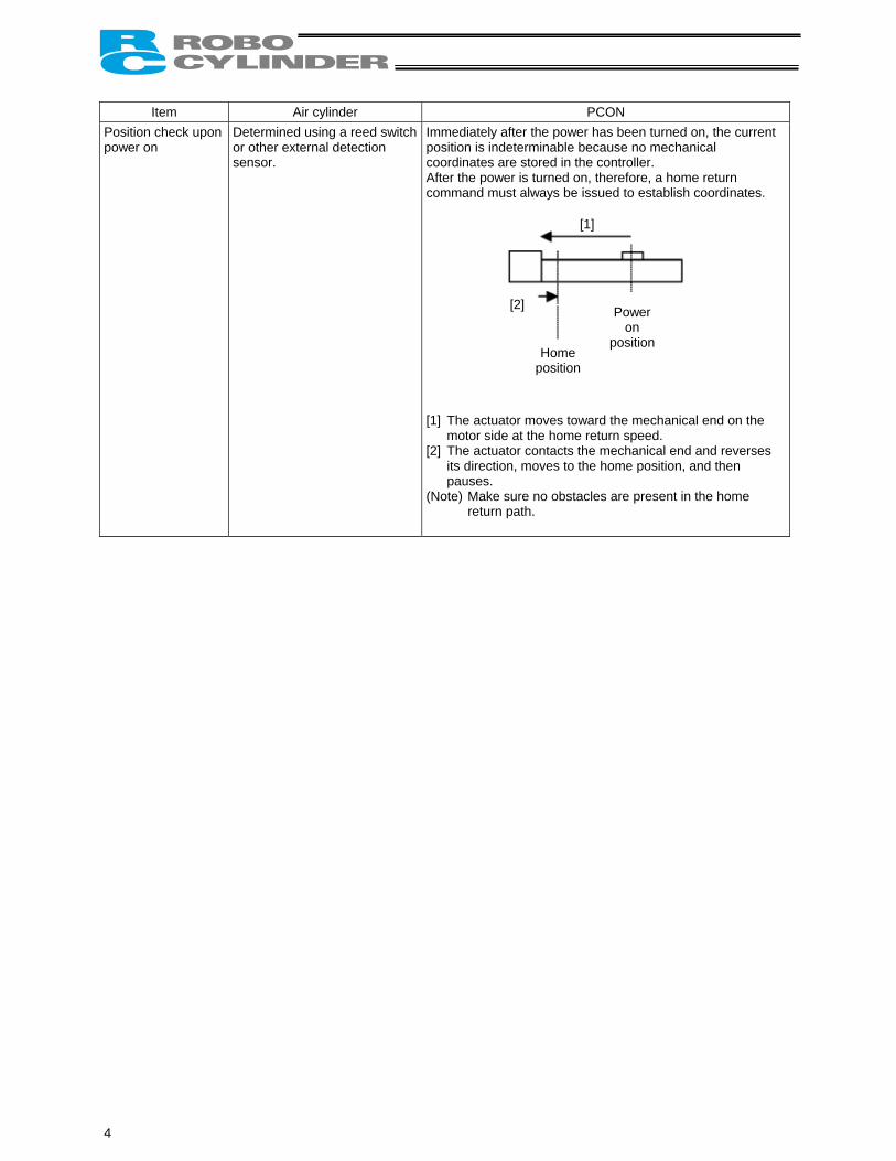
Item Air cylinder PCON Position check upon power on
Determined using a reed switch or other external detection sensor.
Immediately after the power has been turned on, the current position is indeterminable because no mechanical coordinates are stored in the controller. After the power is turned on, therefore, a home return command must always be issued to establish coordinates. [1] The actuator moves toward the mechanical end on the
motor side at the home return speed. [2] The actuator contacts the mechanical end and reverses
its direction, moves to the home position, and then pauses.
(Note) Make sure no obstacles are present in the home return path.
[1]
[2]
Home position
Power on
position
4
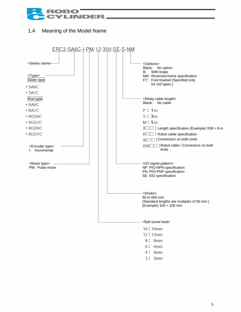
1.4 Meaning of the Model Name
<Series name>
<Type> Slider type
Rod type
Encoder type>
Motor type> motor
<Options> Blank: No option B: With brake NM: Reversed-home specification FT: Foot bracket (Specified only
for rod types.)
<Relay cable length> Blank: No cable
Length specification (Example) X08 = 8 m
Robot cable specification
Connectors on both ends
<Stroke> 50 to 600 mm (Standard lengths are multiples of 50 mm.) (Example) 100 = 100 mm <Ball screw lead>
Robot cable / Connectors on both ends
<I/O signal pattern> NP: PIO-NPN specification PN: PIO-PNP specification SE: SIO specification
<I: Incremental <PM: Pulse
5
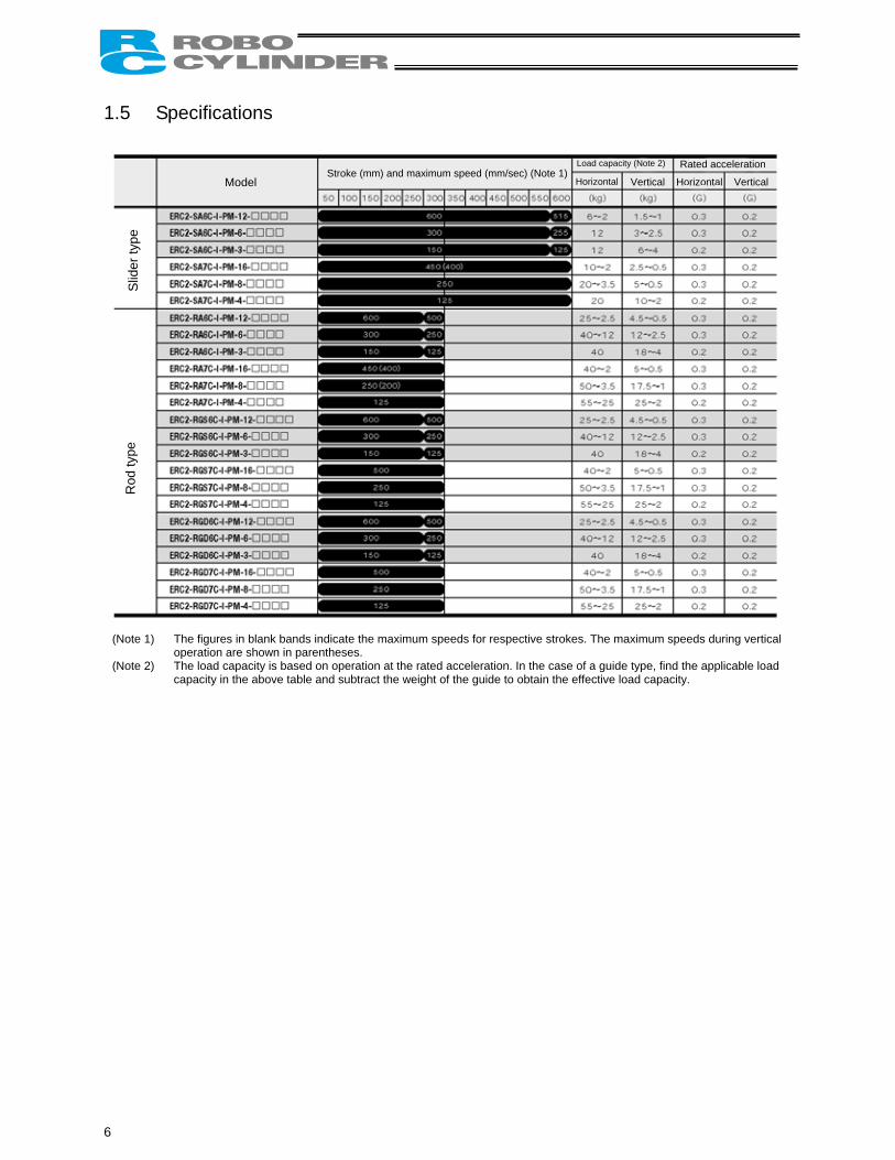
1.5 Specifications
Model Stroke (mm) and maximum speed (mm/sec) (Note 1)
Load capacity (Note 2) Rated acceleration
Slid
er ty
pe
Rod
type
(Note 1) The figures in blank bands indicate the maximum speeds for respective strokeoperation are shown in parentheses.
(Note 2) The load capacity is based on operation at the rated acceleration. In the case capacity in the above table and subtract the weight of the guide to obtain the e
6
Horizontal
s. The ma
of a guide ffective loa
Vertical
ximum sp
type, findd capac
Horizontal
eeds durin
the applicaity.
Vertical
g vertical
ble load
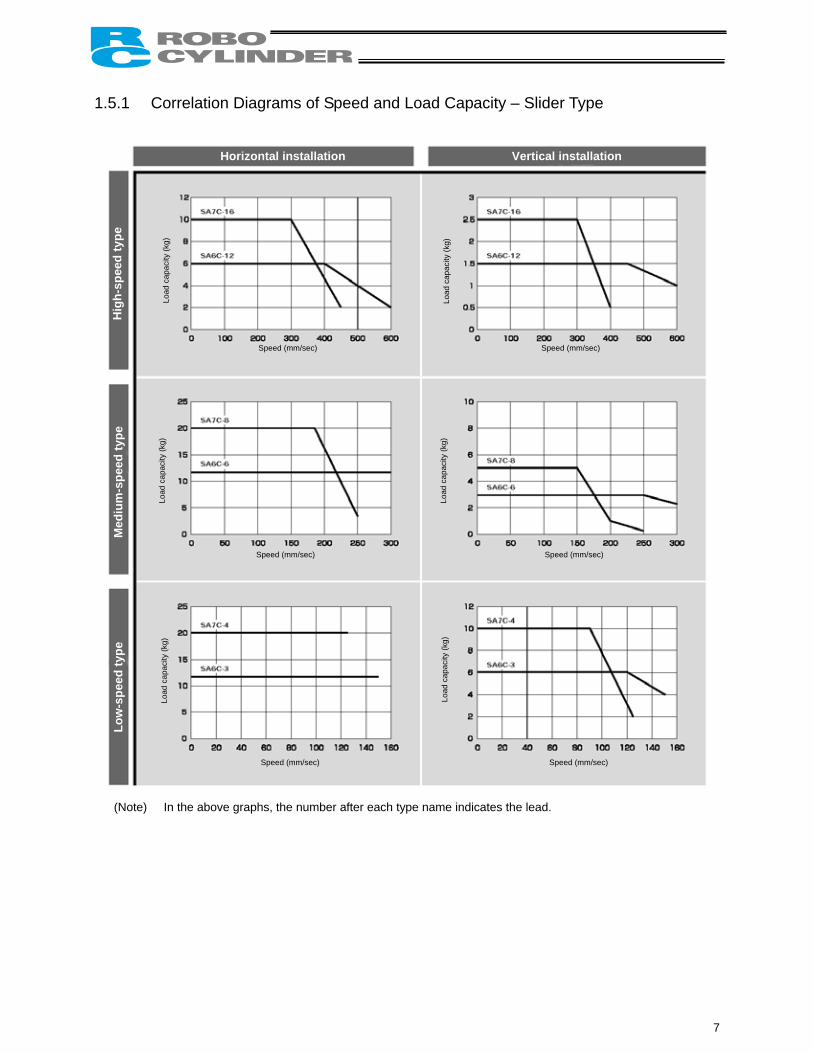
1.5.1 Correlation Diagrams of Speed and Load Capacity – Slider Type
(Note) In the above graphs, the number after each type name indicates the lead.
Horizontal installation Vertical installation
Hig
h-sp
eed
type
Load
cap
acity
(kg)
Speed (mm/sec)
Med
ium
-spe
ed ty
pe
Low
-spe
ed ty
pe
Load
cap
acity
(kg)
Load
cap
acity
(kg)
Load
cap
acity
(kg)
Speed (mm/sec)
Speed (mm/sec) Speed (mm/sec)
Speed (mm/sec) Speed (mm/sec)
Load
cap
acity
(kg)
Load
cap
acity
(kg)
7
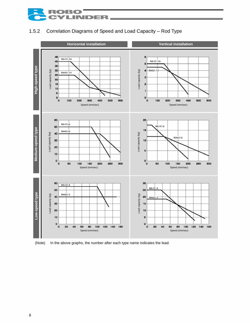
1.5.2 Correlation Diagrams of Speed and Load Capacity – Rod Type
(Note) In the above graphs, the number after each type name indicates the lead.
Horizontal installation Vertical installation
Hig
h-sp
eed
type
Load
cap
acity
(kg)
Speed (mm/sec)
Med
ium
-spe
ed ty
pe
Low
-spe
ed ty
pe
Load
cap
acity
(kg)
Load
cap
acity
(kg)
Load
cap
acity
(kg)
Speed (mm/sec)
Speed (mm/sec) Speed (mm/sec)
Speed (mm/sec) Speed (mm/sec)
Load
cap
acity
(kg)
Load
cap
acity
(kg)
8
Load Applied to the Actuator (1) Slider type • Keep the load applied to the slider below the value stated in the applicable specification item.
In particular, pay attention to the moment applied to the slider, allowable overhung length and load capacity. • If the slider is used in an overhung application with the load extending in the Y-axis direction, keep moments Ma
and Mc to one-half the rated moment or less to prevent the base from deforming. (2) Rod type • Keep the load applied to the rod below the value specified in the catalog. • Make sure the center of the rod axis corresponds to the moving direction of the load.
• Application of lateral load may cause an actuator damage or breakdown. • If the rod is to be subjected to lateral load, provide a guide or other support in the
moving direction of the load.
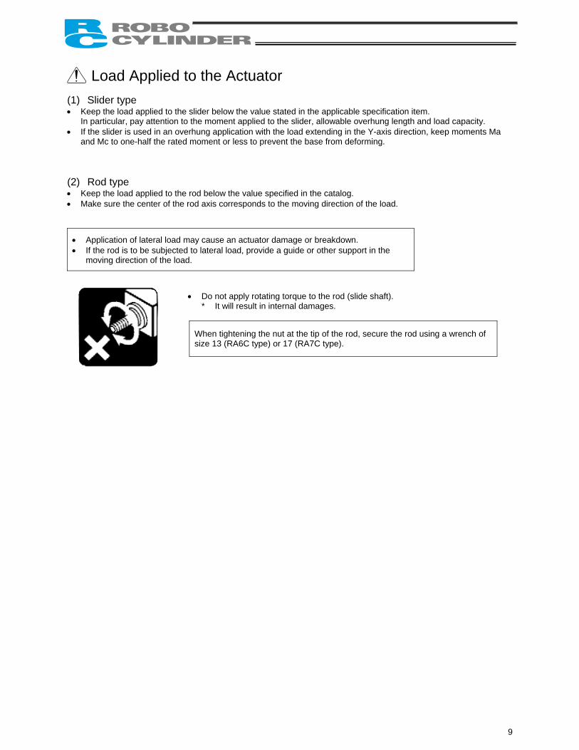
• Do not apply rotating torque to the rod (slide shaft). * It will result in internal damages.
When tightening the nut at the tip of the rod, secure the rod using a wrench of size 13 (RA6C type) or 17 (RA7C type).
9
1.6 Warranty Period and Scope of Warranty The ERC2-SE you have purchased passed IAI’s shipping inspection implemented under the strictest standards. The unit is covered by the following warranty: 1. Warranty Period
The warranty period shall be one of the following periods, whichever ends first: • 18 months after shipment from our factory • 12 months after delivery to a specified location
2. Scope of Warranty
If an obvious manufacturing defect is found during the above period under an appropriate condition of use, IAI will repair the defect free of charge. Note, however, that the following items are excluded from the scope of warranty:
• Aging such as natural discoloration of coating • Wear of a consumable part due to use • Noise or other sensory deviation that doesn’t affect the mechanical function • Defect caused by inappropriate handling or use by the user • Defect caused by inappropriate or erroneous maintenance/inspection • Defect caused by use of a part other than IAI’s genuine part • Defect caused by an alteration or other change not approved by IAI or its agent • Defect caused by an act of God, accident, fire, etc.
The warranty covers only the product as it has been delivered and shall not cover any losses arising in connection with the delivered product. The defective product must be brought to our factory for repair.
Please read the above conditions of warranty carefully.
10
1.7 Transportation and Handling 1.7.1 Handling before Unpacking Exercise due caution when transporting or handling the box containing the actuator, by not applying impact on the box as a result of collision or dropping. • If the box is heavy, one person should not carry it by himself. • Place the box in a level surface. • Do not step on the box. • Do not place on the box any heavy object that may cause the box to deform or other object with a section where
loads will concentrate. 1.7.2 Handling after Unpacking Once removed out of the box, hold the actuator by the frame if it is a rod type, or by the base if it is a slider type. • When carrying the actuator, be careful not to allow it to collide with other objects. In particular, pay attention to the
front bracket, motor bracket and motor cover. • Do not exert excessive force on each part of the actuator. In particular, pay attention to the motor cover and
cables. • When unpacking, exercise due caution not to let the actuator drop and sustain damage to its mechanism. • If the actuator is damaged during the shipment or any of the items is found missing, please contact IAI’s Technical
Support immediately. Supplement) Refer to 2.1, “Name of Each Part,” for the name of each part of the actuator.
11
1.8 Installation Environment and Noise Elimination
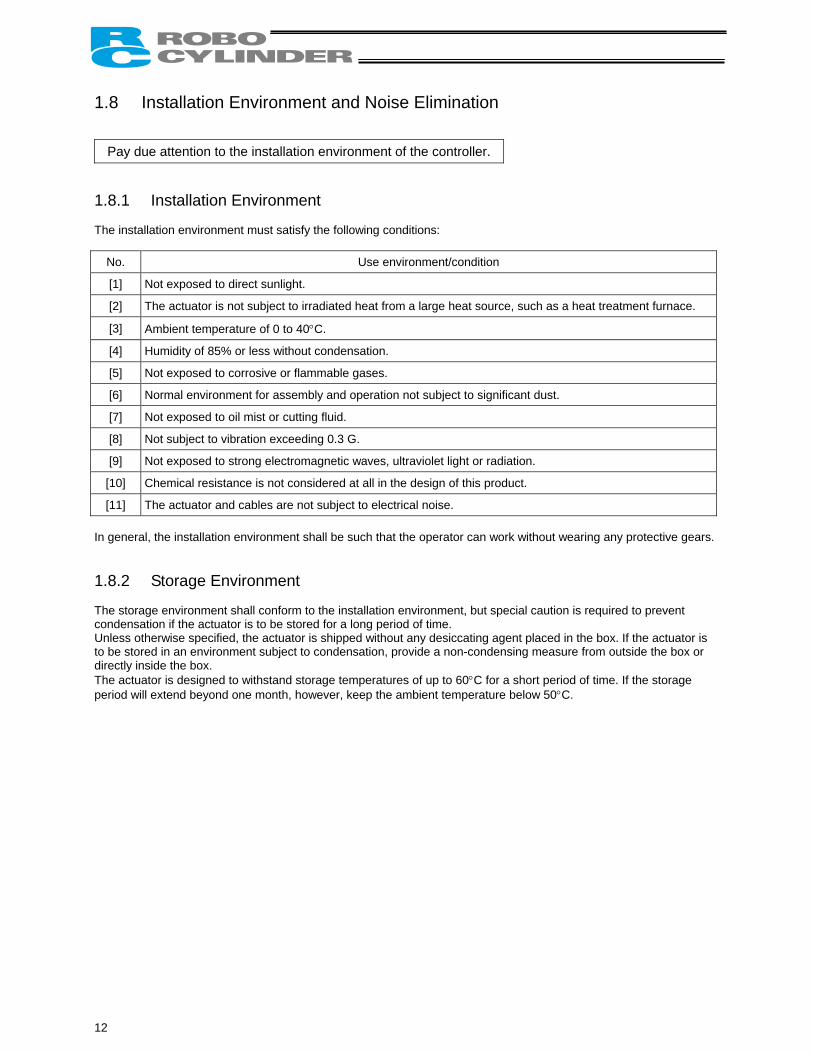
Pay due attention to the installation environment of the controller. 1.8.1 Installation Environment The installation environment must satisfy the following conditions:
No. Use environment/condition
[1] Not exposed to direct sunlight.
[2] The actuator is not subject to irradiated heat from a large heat source, such as a heat treatment furnace.
[3] Ambient temperature of 0 to 40°C.
[4] Humidity of 85% or less without condensation.
[5] Not exposed to corrosive or flammable gases.
[6] Normal environment for assembly and operation not subject to significant dust.
[7] Not exposed to oil mist or cutting fluid.
[8] Not subject to vibration exceeding 0.3 G.
[9] Not exposed to strong electromagnetic waves, ultraviolet light or radiation.
[10] Chemical resistance is not considered at all in the design of this product.
[11] The actuator and cables are not subject to electrical noise. In general, the installation environment shall be such that the operator can work without wearing any protective gears. 1.8.2 Storage Environment The storage environment shall conform to the installation environment, but special caution is required to prevent condensation if the actuator is to be stored for a long period of time. Unless otherwise specified, the actuator is shipped without any desiccating agent placed in the box. If the actuator is to be stored in an environment subject to condensation, provide a non-condensing measure from outside the box or directly inside the box. The actuator is designed to withstand storage temperatures of up to 60°C for a short period of time. If the storage period will extend beyond one month, however, keep the ambient temperature below 50°C.
12
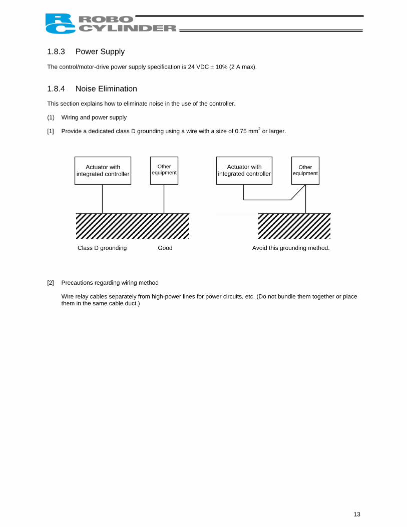
1.8.3 Power Supply The control/motor-drive power supply specification is 24 VDC ± 10% (2 A max). 1.8.4 Noise Elimination This section explains how to eliminate noise in the use of the controller. (1) Wiring and power supply [1] Provide a dedicated class D grounding using a wire with a size of 0.75 mm2 or larger.
Class D grounding Good Avoid this grounding method.
Actuator with integrated controller
Other equipment
Other equipment
Actuator with integrated controller
[2] Precautions regarding wiring method
Wire relay cables separately from high-power lines for power circuits, etc. (Do not bundle them together or place them in the same cable duct.)
13
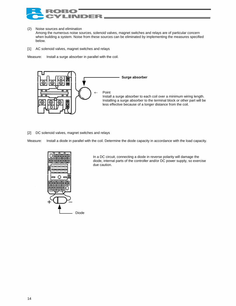
(2) Noise sources and elimination
Among the numerous noise sources, solenoid valves, magnet switches and relays are of particular concern when building a system. Noise from these sources can be eliminated by implementing the measures specified below.
[1] AC solenoid valves, magnet switches and relays Measure: Install a surge absorber in parallel with the coil.
← Point
Install a surge absorber to each coil over a minimum wiring length. Installing a surge absorber to the terminal block or other part will be less effective because of a longer distance from the coil.
Surge absorber [2] DC solenoid valves, magnet switches and relays Measure: Install a diode in parallel with the coil. Determine the diode capacity in accordance with the load capacity.
In a DC circuit, connecting a diode in reverse polarity will damage the diode, internal parts of the controller and/or DC power supply, so exercise due caution.
Diode
14

1.9 Cabling • The standard relay cables have excellent flexibility to withstand fatigue from flexural loads, but they are not robot
cables. Therefore, avoid storing the standard relay cables in movable cable ducts laid at a small radius. If they must be stored in movable cable ducts, use robot cables.
• In an application where the cable cannot be fixed, keep the cable from receiving a deflecting load exceeding its own weight, use a self-standing cable hose, provide a large bending radius along the wiring path, or provide other measure to minimize the load applied to the cable.
• Do not cut the cable for the purpose of extension, length reduction or reconnection. If you intend to change the cable layout, please consult IAI.
15

16
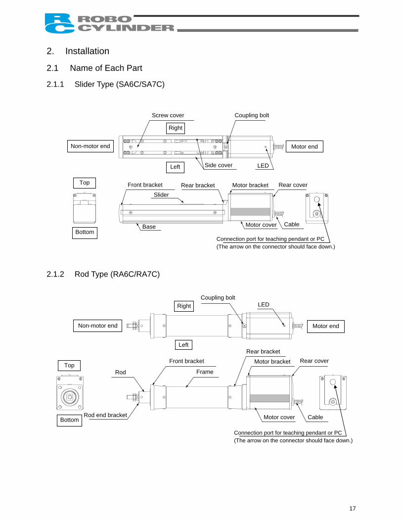
2. Installation 2.1 Name of Each Part 2.1.1 Slider Type (SA6C/SA7C)
Connection port for teaching pendant or PC (The arrow on the connector should face down.)
Non-motor end
Screw cover Coupling bolt
Right
Left
Motor end
Side cover LED
Top
Bottom
Front bracket
Slider Rear bracket Motor bracket Rear cover
Base Motor cover Cable
2.1.2 Rod Type (RA6C/RA7C)
Connection port for teaching pendant or PC
LED
Non-motor end Motor end
Right
Left
Coupling bolt
Front bracket Rear bracket
Motor bracket Rear cover
Motor cover Cable
Rod Frame
Rod end bracket
Top
Bottom
(The arrow on the connector should face down.)
17
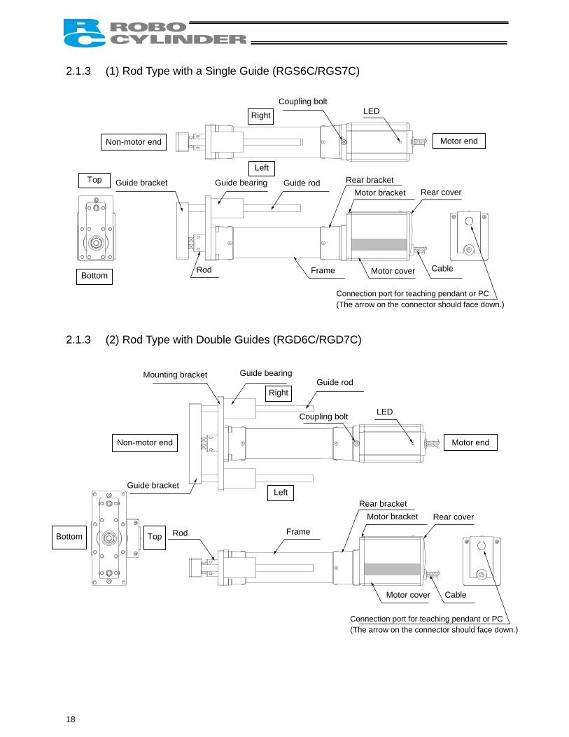
2.1.3 (1) Rod Type with a Single Guide (RGS6C/RGS7C)
Connection port for teaching pendant or PC (The arrow on the connector should face down.)
Non-motor end
Coupling bolt
Right
Left
Motor end
LED
Top
Bottom Cable Motor cover Rod Frame
Rear bracketMotor bracket Rear cover
Guide bracket Guide bearing Guide rod
2.1.3 (2) Rod Type with Double Guides (RGD6C/RGD7C)
Connection port for teaching pendant or PC (The arrow on the connector should face down.)
Non-motor end
Coupling bolt
Right
Left
Motor end
LED
Top Bottom
Cable Motor cover
Rod Frame
Rear bracket Motor bracket Rear cover
Mounting bracket Guide bearing Guide rod
Guide bracket
18
2.2 Installation 2.2.1 Slider Type
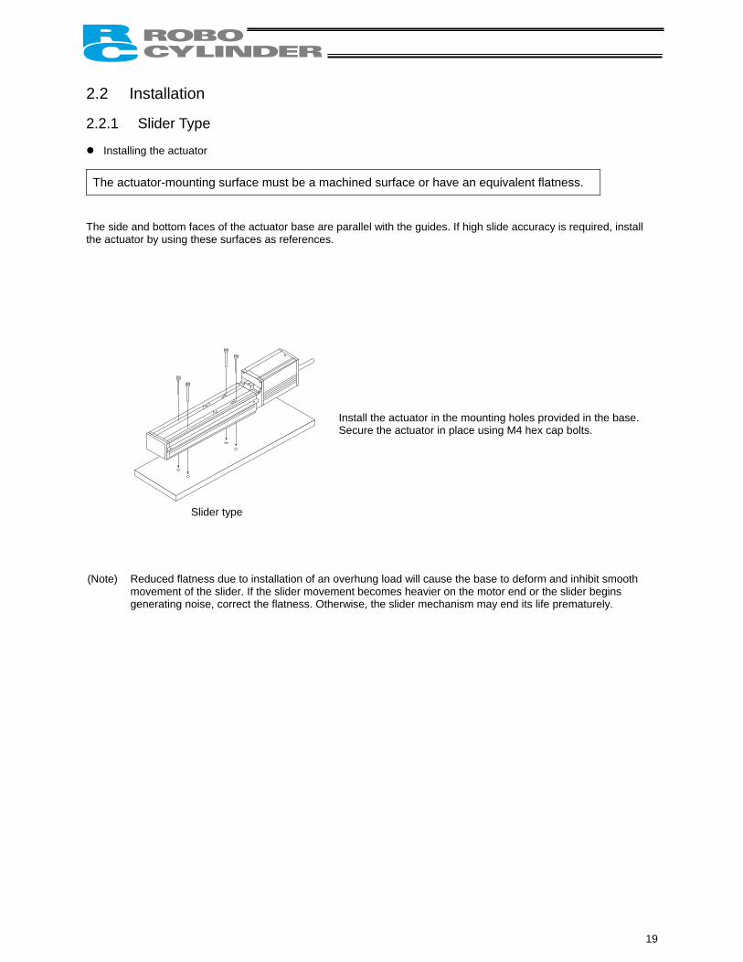
Installing the actuator
The actuator-mounting surface must be a machined surface or have an equivalent flatness. The side and bottom faces of the actuator base are parallel with the guides. If high slide accuracy is required, install the actuator by using these surfaces as references.
Install the actuator in the mounting holes provided in the base. Secure the actuator in place using M4 hex cap bolts.
Slider type
(Note) Reduced flatness due to installation of an overhung load will cause the base to deform and inhibit smooth
movement of the slider. If the slider movement becomes heavier on the motor end or the slider begins generating noise, correct the flatness. Otherwise, the slider mechanism may end its life prematurely.
19
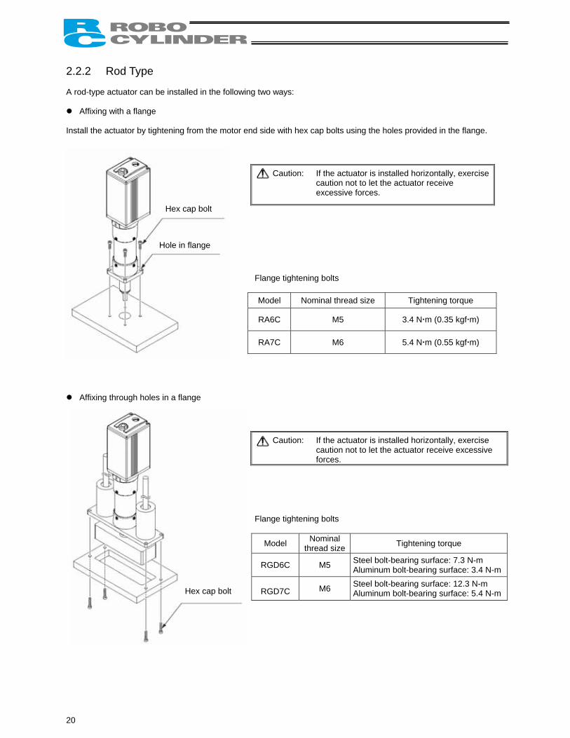
2.2.2 Rod Type A rod-type actuator can be installed in the following two ways:
Affixing with a flange Install the actuator by tightening from the motor end side with hex cap bolts using the holes provided in the flange.
Caution: If the actuator is installed horizontally, exercise caution not to let the actuator receive excessive forces.
Flange tightening bolts
Model Nominal thread size Tightening torque
RA6C M5 3.4 N m (0.35 kgf m)
RA7C M6 5.4 N m (0.55 kgf m)
Affixing through holes in a flange
Caution: If the actuator is installed horizontally, exercise caution not to let the actuator receive excessive forces.
Flange tightening bolts
Model Nominal thread size Tightening torque
RGD6C M5 Steel bolt-bearing surface: 7.3 N-m Aluminum bolt-bearing surface: 3.4 N-m
RGD7C M6 Steel bolt-bearing surface: 12.3 N-m Aluminum bolt-bearing surface: 5.4 N-m
Hex cap bolt
Hole in flange
Hex cap bolt
20
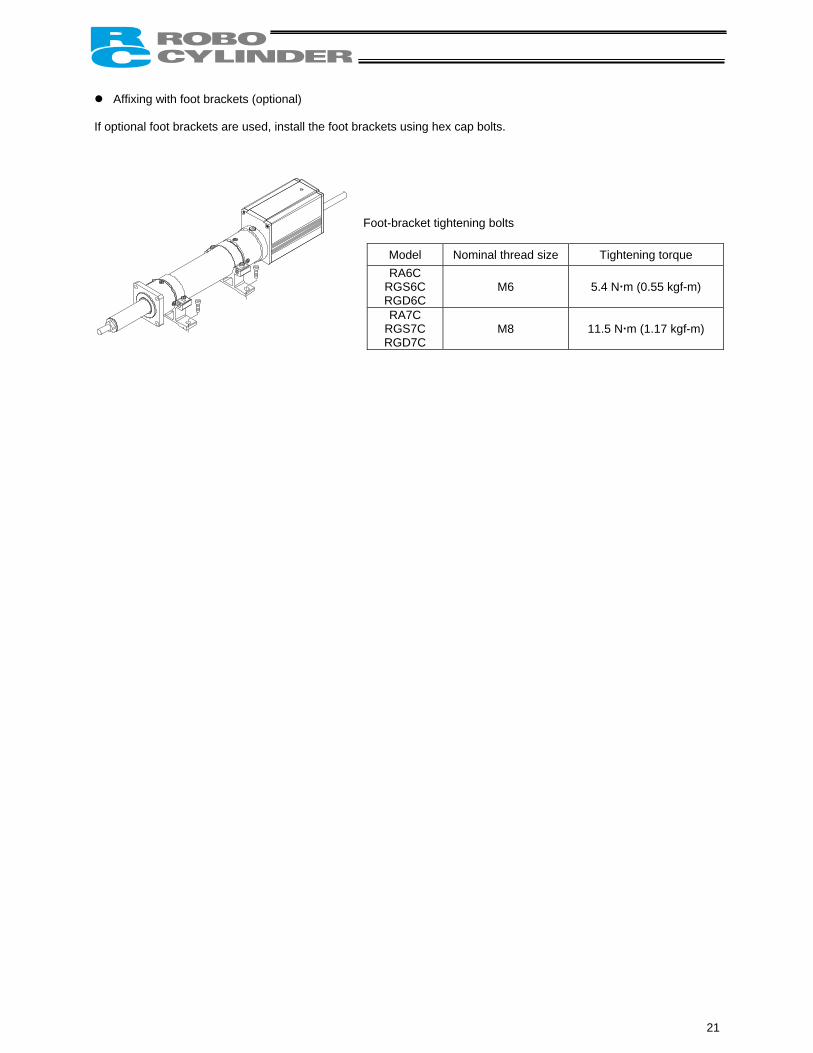
Affixing with foot brackets (optional) If optional foot brackets are used, install the foot brackets using hex cap bolts.
Foot-bracket tightening bolts
Model Nominal thread size Tightening torque RA6C
RGS6C RGD6C
M6 5.4 N m (0.55 kgf-m)
RA7C RGS7C RGD7C
M8 11.5 N m (1.17 kgf-m)
21

22
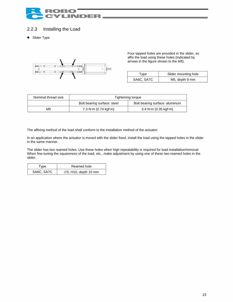
2.2.3 Installing the Load
Slider Type
Four tapped holes are provided in the slider, so affix the load using these holes (indicated by arrows in the figure shown to the left).
Type Slider mounting hole SA6C, SA7C M5, depth 9 mm
Nominal thread size Tightening torque
Bolt bearing surface: steel Bolt bearing surface: aluminum
M5 7.3 N m (0.74 kgf m) 3.4 N m (0.35 kgf m) The affixing method of the load shall conform to the installation method of the actuator. In an application where the actuator is moved with the slider fixed, install the load using the tapped holes in the slider in the same manner. The slider has two reamed holes. Use these holes when high repeatability is required for load installation/removal. When fine-tuning the squareness of the load, etc., make adjustment by using one of these two reamed holes in the slider.
Type Reamed hole SA6C, SA7C ∅5, H10, depth 10 mm
23
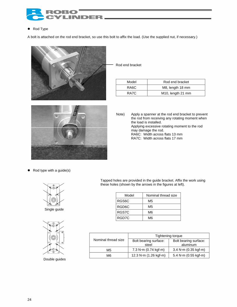
Rod Type A bolt is attached on the rod end bracket, so use this bolt to affix the load. (Use the supplied nut, if necessary.)
Rod end bracket
Model Rod end bracket RA6C M8, length 18 mm RA7C M10, length 21 mm
Note) Apply a spanner at the rod end bracket to prevent the rod from receiving any rotating moment when the load is installed.
Applying excessive rotating moment to the rod may damage the rod.
RA6C: Width across flats 13 mm RA7C: Width across flats 17 mm
Rod type with a guide(s)
Model Nominal thread size RGS6C M5
RGD6C M5 RGS7C M6 RGD7C M6
Tightening torque Nominal thread size Bolt bearing surface:
steel Bolt bearing surface:
aluminum M5 7.3 N m (0.74 kgf-m) 3.4 N m (0.35 kgf-m)
M6 12.3 N m (1.26 kgf-m) 5.4 N m (0.55 kgf-m) Double guides
Tapped holes are provided in the guide bracket. Affix the work using these holes (shown by the arrows in the figures at left).
Single guide
24
3. Electrical Specifications 3.1 Controller
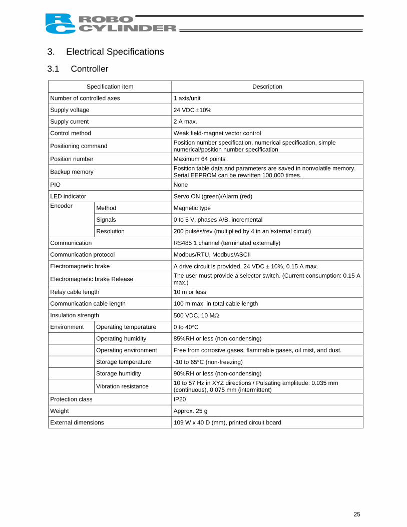
Specification item Description
Number of controlled axes 1 axis/unit
Supply voltage 24 VDC ±10%
Supply current 2 A max.
Control method Weak field-magnet vector control
Positioning command Position number specification, numerical specification, simple numerical/position number specification
Position number Maximum 64 points
Backup memory Position table data and parameters are saved in nonvolatile memory. Serial EEPROM can be rewritten 100,000 times.
PIO None
LED indicator Servo ON (green)/Alarm (red)
Method Magnetic type
Signals 0 to 5 V, phases A/B, incremental
Encoder
Resolution 200 pulses/rev (multiplied by 4 in an external circuit)
Communication RS485 1 channel (terminated externally)
Communication protocol Modbus/RTU, Modbus/ASCII
Electromagnetic brake A drive circuit is provided. 24 VDC ± 10%, 0.15 A max.
Electromagnetic brake Release The user must provide a selector switch. (Current consumption: 0.15 A max.)
Relay cable length 10 m or less
Communication cable length 100 m max. in total cable length
Insulation strength 500 VDC, 10 MΩ
Environment Operating temperature 0 to 40°C
Operating humidity 85%RH or less (non-condensing)
Operating environment Free from corrosive gases, flammable gases, oil mist, and dust.
Storage temperature -10 to 65°C (non-freezing)
Storage humidity 90%RH or less (non-condensing)
Vibration resistance 10 to 57 Hz in XYZ directions / Pulsating amplitude: 0.035 mm (continuous), 0.075 mm (intermittent)
Protection class IP20
Weight Approx. 25 g
External dimensions 109 W x 40 D (mm), printed circuit board
25
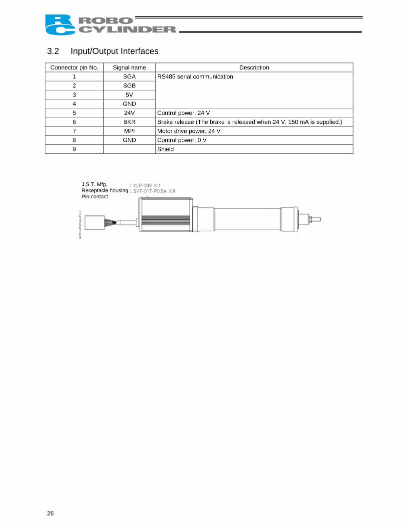
3.2 Input/Output Interfaces Connector pin No. Signal name Description
1 SGA 2 SGB 3 5V 4 GND
RS485 serial communication
5 24V Control power, 24 V 6 BKR Brake release (The brake is released when 24 V, 150 mA is supplied.) 7 MPI Motor drive power, 24 V 8 GND Control power, 0 V 9 Shield
J.S.T. Mfg. Receptacle housing Pin contact
26
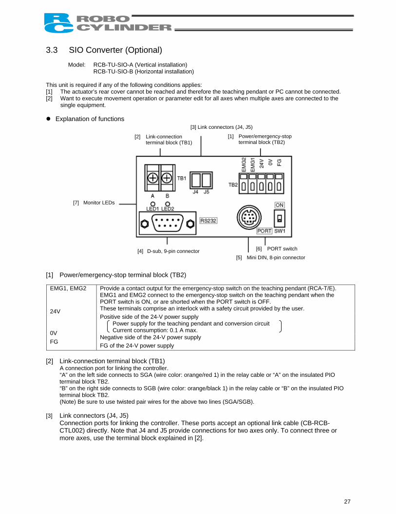
3.3 SIO Converter (Optional)
Model: RCB-TU-SIO-A (Vertical installation) RCB-TU-SIO-B (Horizontal installation)
This unit is required if any of the following conditions applies: [1] The actuator’s rear cover cannot be reached and therefore the teaching pendant or PC cannot be connected. [2] Want to execute movement operation or parameter edit for all axes when multiple axes are connected to the
single equipment.
Explanation of functions
[2] Link-connection terminal block (TB1)
[1] Power/emergency-stop terminal block (TB2)
[7] Monitor LEDs
[4] D-sub, 9-pin connector [6] PORT switch
[5] Mini DIN, 8-pin connector
[3] Link connectors (J4, J5) [1] Power/emergency-stop terminal block (TB2)
Provide a contact output for the emergency-stop switch on the teaching pendant (RCA-T/E). EMG1 and EMG2 connect to the emergency-stop switch on the teaching pendant when the PORT switch is ON, or are shorted when the PORT switch is OFF. These terminals comprise an interlock with a safety circuit provided by the user. Positive side of the 24-V power supply
Power supply for the teaching pendant and conversion circuit Current consumption: 0.1 A max.
Negative side of the 24-V power supply
EMG1, EMG2
24V 0V FG FG of the 24-V power supply
[2] Link-connection terminal block (TB1)
A connection port for linking the controller. “A” on the left side connects to SGA (wire color: orange/red 1) in the relay cable or “A” on the insulated PIO terminal block TB2. “B” on the right side connects to SGB (wire color: orange/black 1) in the relay cable or “B” on the insulated PIO terminal block TB2. (Note) Be sure to use twisted pair wires for the above two lines (SGA/SGB).
[3] Link connectors (J4, J5)
Connection ports for linking the controller. These ports accept an optional link cable (CB-RCB-CTL002) directly. Note that J4 and J5 provide connections for two axes only. To connect three or more axes, use the terminal block explained in [2].
27
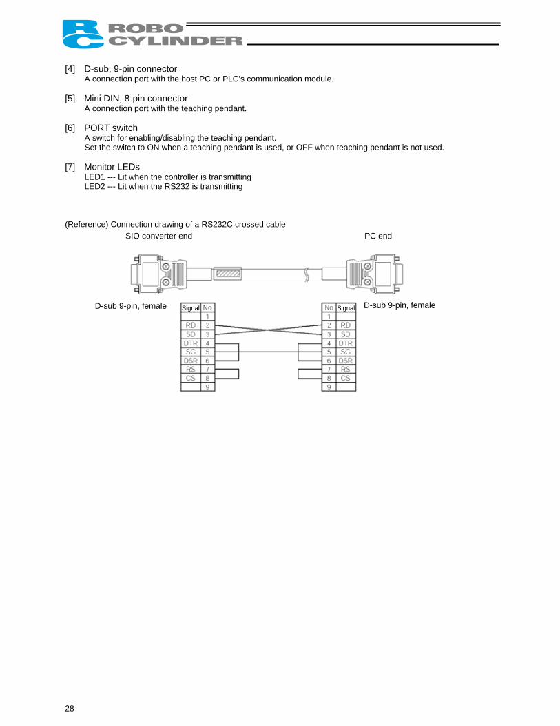
[4] D-sub, 9-pin connector
A connection port with the host PC or PLC’s communication module. [5] Mini DIN, 8-pin connector
A connection port with the teaching pendant. [6] PORT switch
A switch for enabling/disabling the teaching pendant. Set the switch to ON when a teaching pendant is used, or OFF when teaching pendant is not used.
[7] Monitor LEDs
LED1 --- Lit when the controller is transmitting LED2 --- Lit when the RS232 is transmitting
(Reference) Connection drawing of a RS232C crossed cable
SIO converter end PC end
D-sub 9-pin, female D-sub 9-pin, female Signal Signal
28
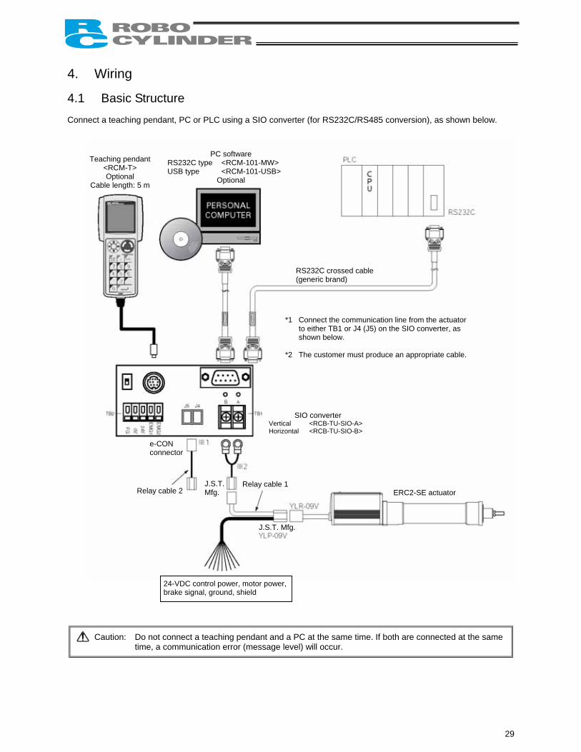
4. Wiring 4.1 Basic Structure Connect a teaching pendant, PC or PLC using a SIO converter (for RS232C/RS485 conversion), as shown below. PC software
RS232C type <RCM-101-MW> USB type <RCM-101-USB>
Optional
Teaching pendant <RCM-T> Optional
Cable length: 5 m
*1
*2
SVertical Horizonta
e-CON connector
24-VDC control power, motor power, brake signal, ground, shield
Caution: Do not connect a teaching pendant and a Ptime, a communication error (message leve
RS232C crossed cable(generic brand)
Connect the communication line from the actuator to either TB1 or J4 (J5) on the SIO converter, as shown below.
The customer must produce an appropriate cable.
IO converter <RCB-TU-SIO-A>
l <RCB-TU-SIO-B>
Relay cable 2
ERC2-SE actuator J.S.T.Mfg.Relay cable 1
J.S.T. Mfg.
C at the same time. If both are connected at the same l) will occur.
29
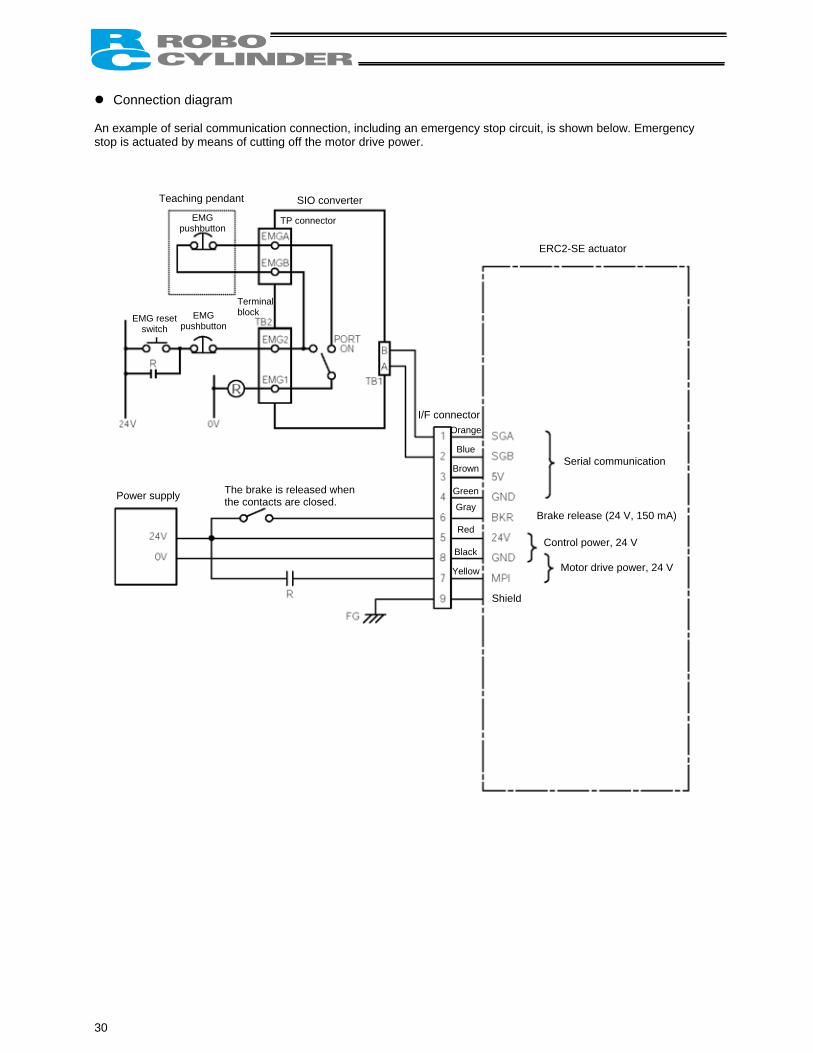
Connection diagram An example of serial communication connection, including an emergency stop circuit, is shown below. Emergency stop is actuated by means of cutting off the motor drive power.
Teaching pendant
pus
SIO converter
TP connector
EMG reset switch pus
Power supply
30
EMG
ERC2-SE actuator
hbutton
EMG hbutton
Tb
erminal lock
Serial communication
Orange
Blue
Brown
Green
I/F connector
The brake is released whenthe contacts are closed.
GrayRed
Black
Yellow
Brake release (24 V, 150 mA)
Control power, 24 V
Motor drive power, 24 V
Shield
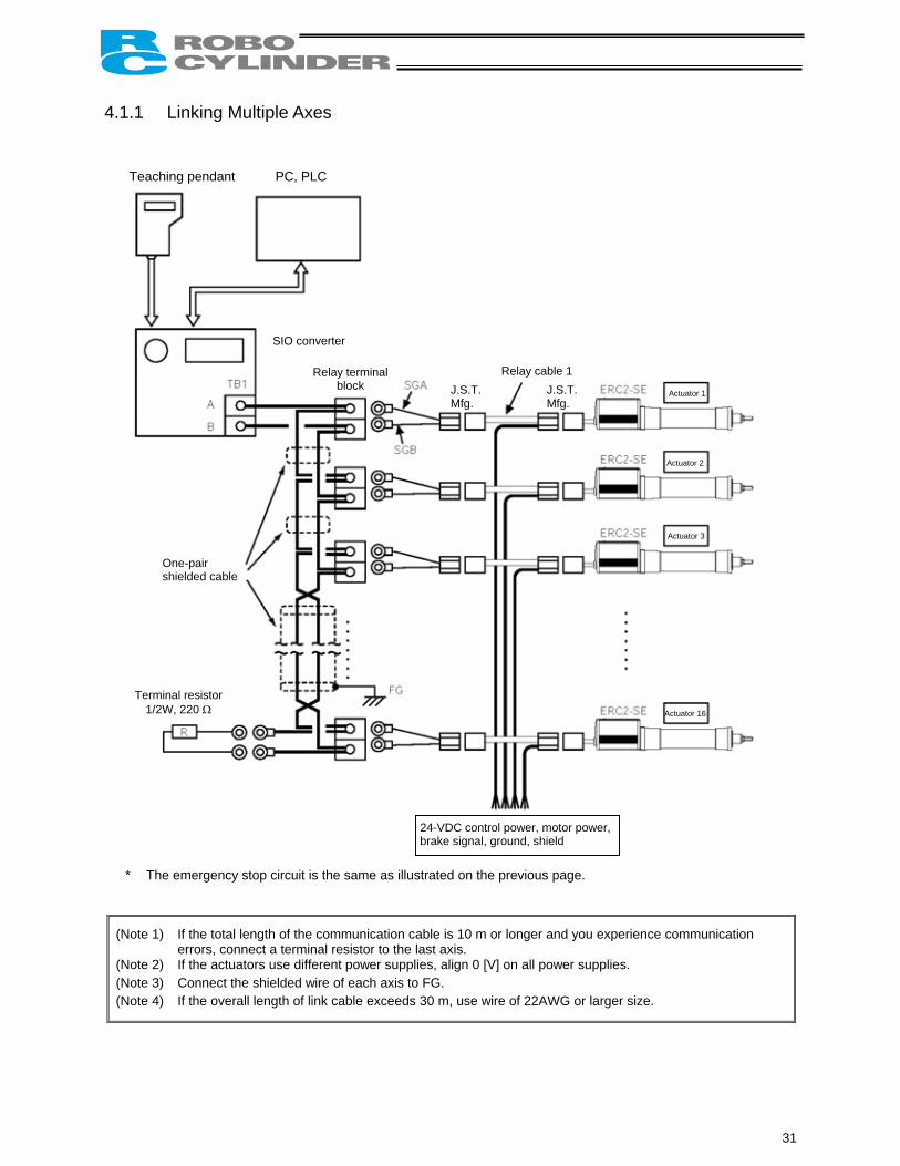
4.1.1 Linking Multiple Axes
* The emergency stop circuit is the same as illustrated
(Note 1) If the total length of the communication cable iserrors, connect a terminal resistor to the last ax
(Note 2) If the actuators use different power supplies, al(Note 3) Connect the shielded wire of each axis to FG. (Note 4) If the overall length of link cable exceeds 30 m,
Teaching pendant PC, PLC
Relay terminal block
Actuator 1
One-pair shielded cable
Terminal resistor 1/2W, 220 Ω
SIO converter
Relay cable 1
24-VDbrake
J.S.T. Mfg.
on the previous
10 m or longer ais. ign 0 [V] on all po
use wire of 22A
C control power, msignal, ground, shi
J.S.T.Mfg.
page.
nd you experience communication
wer supplies.
WG or larger size.
Actuator 2
Actuator 3
Actuator 16
otor power, eld
31
4.1.2 Address Assignment If multiple axes are connected, a slave number must be assigned to each axis so that the host can recognize the corresponding actuator. Assign addresses in the setting screen of the teaching pendant or PC.
Overview of operation on the PC [1] Open the main window → [2] Click Setup (S) → [3] Bring the cursor to Controller Setup (C) → [4] Bring the
cursor to Assign Address (N) and click the mouse → [5] Enter an appropriate number in the address table. Overview of operation on the teaching pendant RCM-T
[1] Open the User Adjustment screen → [2] Use the key to bring the cursor to Address No. → [3] Enter an appropriate address and press the ENTER key → [4] Enter “2” under Adjustment No. and press the ENTER key.
Overview of operation on the simple teaching pendant RCM-E [1] Open the User Adjustment screen → [2] Press the ENTER key to open the screen showing Address No. →
[3] Enter an appropriate address and press the ENTER key → [4] Enter “2” under Adjustment No. and press the ENTER key.
Refer to the operation manual for your teaching pendant or PC software for the specific operating procedure.
Caution: In the actual process of assigning addresses, the teaching pendant or PC and the target actuator must have a one-on-one link. Therefore, disconnect the communication cables (SGA/SGB) from other axes to tentatively provide a condition where not more than one axis is connected.
32
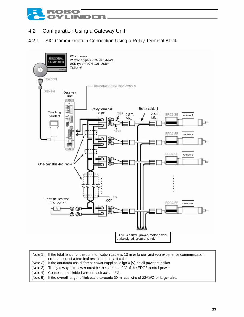
4.2 Configuration Using a Gateway Unit 4.2.1 SIO Communication Connection Using a Relay Terminal Block
(Note 1) If the total length of the communication cable is 10 m or longer anerrors, connect a terminal resistor to the last axis.
(Note 2) If the actuators use different power supplies, align 0 [V] on all pow(Note 3) The gateway unit power must be the same as 0 V of the ERC2 co(Note 4) Connect the shielded wire of each axis to FG. (Note 5) If the overall length of link cable exceeds 30 m, use wire of 22AW
PC software RS232C type <RCM-101-MW> USB type <RCM-101-USB> Optional
Teaching pendant
Relay terminal block
Actuator 1
One-pair shielded cable
Terminal resistor 1/2W, 220 Ω
Gateway unit
Relay cable 1 J
M
24-VDC control power, mbrake signal, ground, shi
J.S.T.Mfg.
.S.T. fg.
d you experience communication
er supplies. ntrol power.
G or larger size.
Actuator 2
Actuator 3
Actuator 16
otor power, eld
33
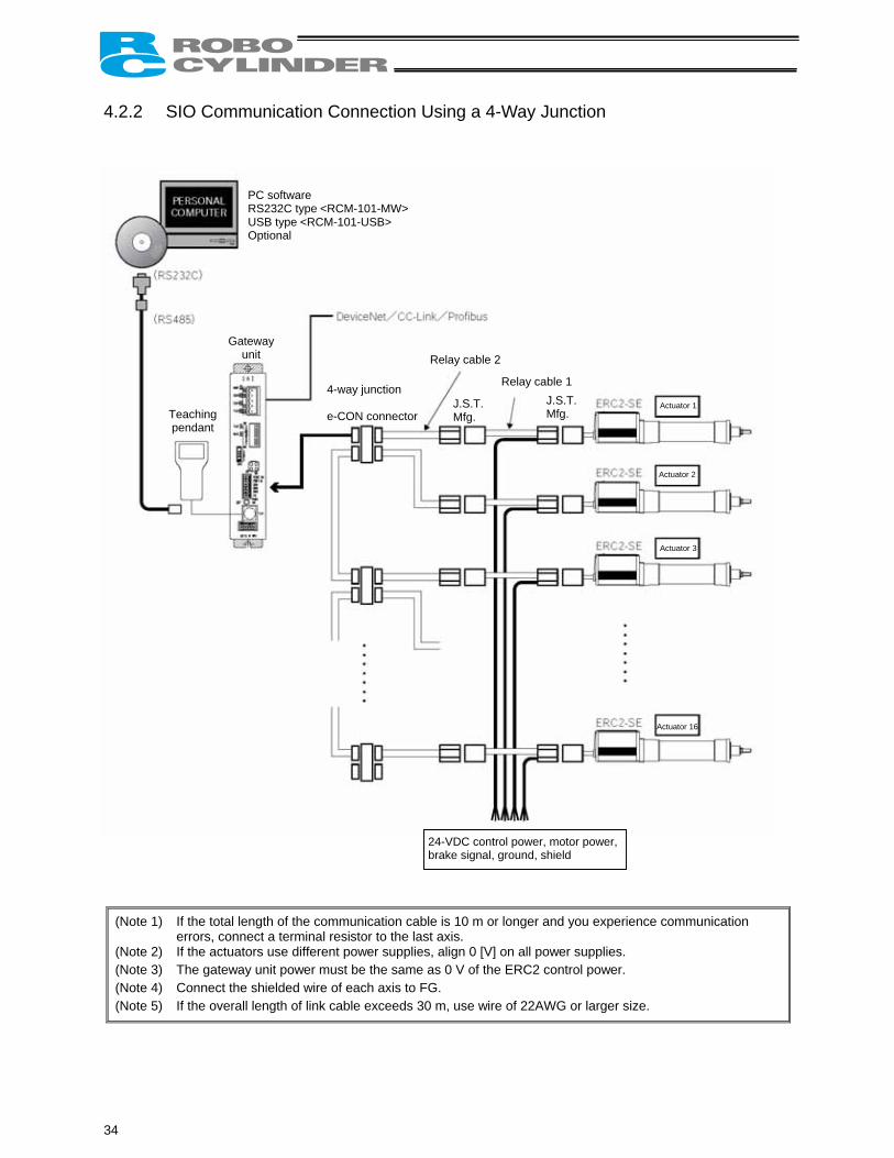
4.2.2 SIO Communication Connection Using a 4-Way Junction
(Note 1) If the total length of the communication cable is 10 m or longer aerrors, connect a terminal resistor to the last axis.
(Note 2) If the actuators use different power supplies, align 0 [V] on all po(Note 3) The gateway unit power must be the same as 0 V of the ERC2 c(Note 4) Connect the shielded wire of each axis to FG. (Note 5) If the overall length of link cable exceeds 30 m, use wire of 22AW
PC software RS232C type <RCM-101-MW> USB type <RCM-101-USB> Optional
Teaching pendant
Actuator 1
Gateway unit
Relay cable 1
Relay cable 2
24-VDC control power,brake signal, ground, s
34
J.S.T.Mfg.
J.S.T.Mfg.
4-way junction e-CON connector
nd you experience communication
wer supplies. ontrol power.
G or larger size.
Actuator 2
Actuator 3
Actuator 16
motor power, hield
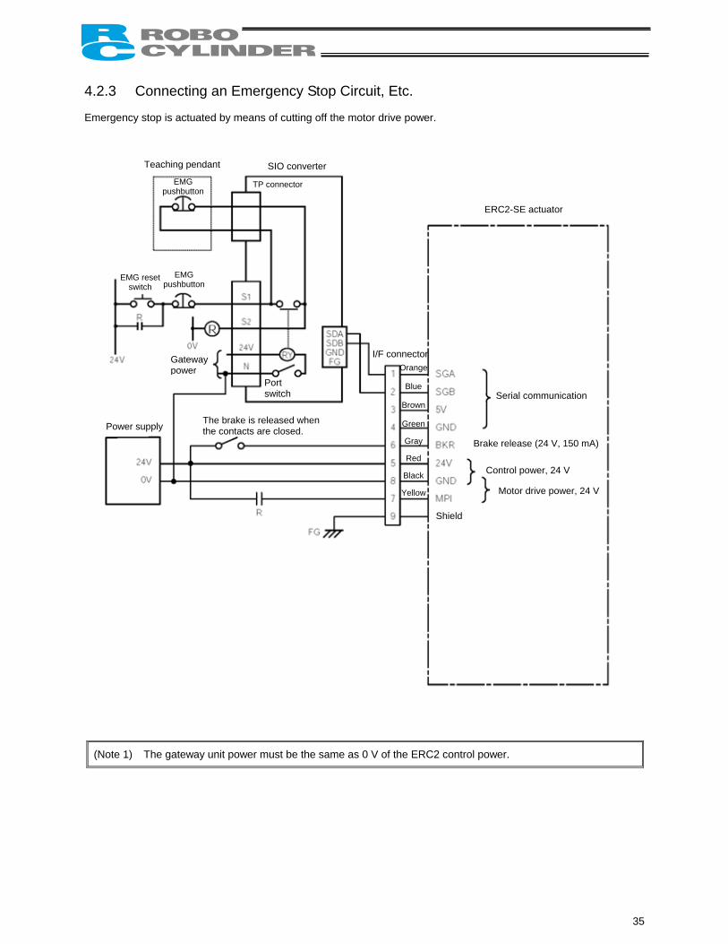
4.2.3 Connecting an Emergency Stop Circuit, Etc. Emergency stop is actuated by means of cutting off the motor drive power.
(Note 1) The ga
Teaching pendant E
pus
SIO converter
TP connector
EMG reset switch pus
Power supply
MG
teway
Serial communication
Orange
Blue
Brown
Green
ERC2-SE actuator
hbutton
EMG hbutton
h
I/F connector
The brake is released whenthe contacts are closed.
Gatewaypower
unit power m
Port switc
ust be the same as 0 V of the ERC2 control power.
Gray
Red
Black
Yellow
Brake release (24 V, 150 mA)
Control power, 24 V
Motor drive power, 24 V
Shield
35
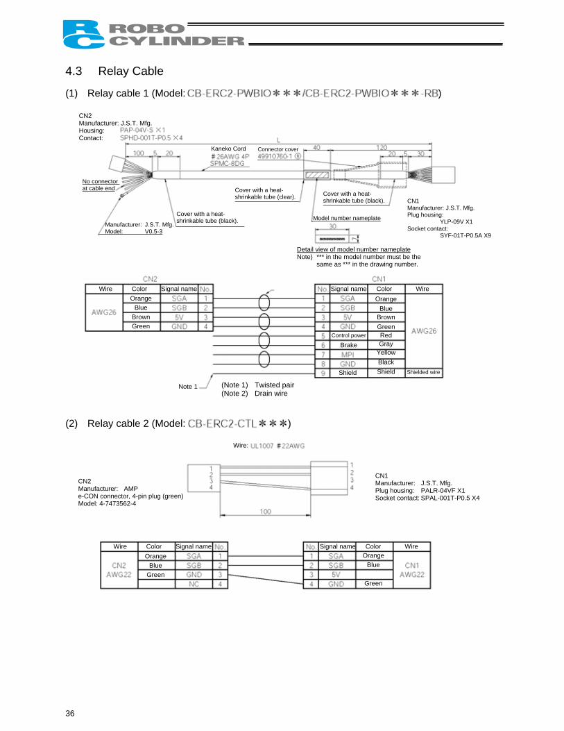
4.3 Relay Cable (1) Relay cable 1 (Model: )
Orange Blue
Brown Green Red Gray
Yellow Black Shield
Orange Blue
Brown Green
CN2 Manufacturer: J.S.T. Mfg. Housing: Contact:
Kaneko Cord Connector cover
No connector at cable end
Manufacturer: J.S.T. Mfg. Model: V0.5-3
Cover with a heat-shrinkable tube (black).
Cover with a heat-shrinkable tube (clear). Cover with a heat-
shrinkable tube (black).
Model number nameplate
CN1 Manufacturer: J.S.T. Mfg. Plug housing:
YLP-09V X1 Socket contact:
SYF-01T-P0.5A X9
Detail view of model number nameplate Note) *** in the model number must be the
same as *** in the drawing number.
Wire Color Signal name Signal name Color Wire
(Note 1) Twisted pair(Note 2) Drain wire
Control power
Brake
Shield Shielded wire
Note 1
(2) Relay cable 2 (Model: )
Orange Blue
Green
Orange Blue
Green
Wire:
CN1 Manufacturer: J.S.T. Mfg. Plug housing: PALR-04VF X1 Socket contact: SPAL-001T-P0.5 X4
CN2 Manufacturer: AMP e-CON connector, 4-pin plug (green) Model: 4-7473562-4
Wire Color Signal name Signal name Color Wire
36

5. Explanation of Operating Functions ERC2-SE actuators support two operation modes: [1] “position number specification mode” in which the actuator is operated by specifying position numbers via serial communication, and [2] “numerical specification mode” in which the actuator is operated by specifying operation data directly as numerical values via serial communication. To move the actuator to a specified position in the “position number specification mode,” basically a position table must be created in advance by entering the target position in the “Position” field. The target position can be specified as an absolute distance from the home (absolute mode), or as an incremental travel from the current position (incremental mode). Once the target position is entered, other fields will be automatically populated with the defaults set by the applicable parameters. The defaults set in the respective fields vary depending on the actuator characteristics.
37
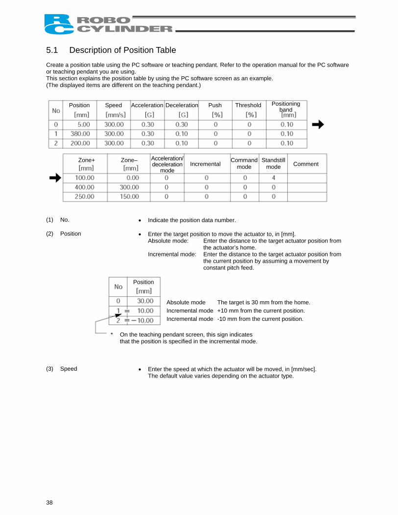
5.1 Description of Position Table Create a position table using the PC software or teaching pendant. Refer to the operation manual for the PC software or teaching pendant you are using. This section explains the position table by using the PC software screen as an example. (The displayed items are different on the teaching pendant.)
Position Speed Acceleration Deceleration Push Threshold
Zone+ Zone– Incremental
Command mode
Stanmo
(1) No. • Indicate the position data number.
(2) Position • Enter the target position to move the actuator to
Absolute mode: Enter the distance to the tathe actuator’s home.
Incremental mode: Enter the distance to the tathe current position by assconstant pitch feed.
Absolute mode The target is 30 mm fIncremental mode +10 mm from the curIncremental mode -10 mm from the curr
On the teaching pendant screen, this sign indicates that the position is specified in the incremental mode.
Position
*
(3) Speed • Enter the speed at which the actuator will be mo
The default value varies depending on the actua
38
Positioningband
dstill de Comment
Acceleration/deceleration
mode
, in [mm]. rget actuator position from
rget actuator position from uming a movement by
rom the home. rent position. ent position.
ved, in [mm/sec]. tor type.
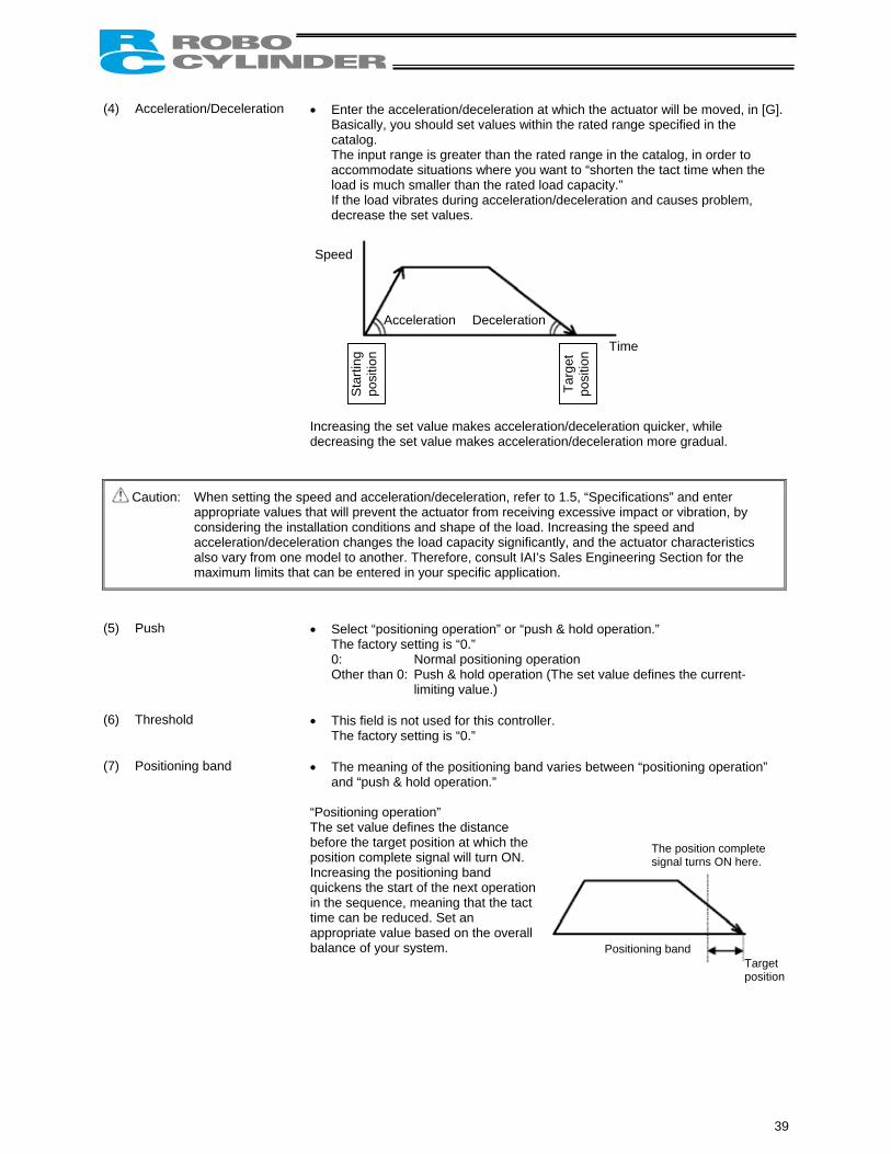
(4) Acceleration/Deceleration • Enter the acceleration/deceleration at which the actuator will be moved, in [G].
Basically, you should set values within the rated range specified in the catalog. The input range is greater than the rated range in the catalog, in order to accommodate situations where you want to “shorten the tact time when the load is much smaller than the rated load capacity.” If the load vibrates during acceleration/deceleration and causes problem, decrease the set values.
Speed
Acceleration Deceleration
Time S
tarti
ng
posi
tion
Targ
et
posi
tion
Increasing the set value makes acceleration/deceleration quicker, while decreasing the set value makes acceleration/deceleration more gradual.
Caution: When setting the speed and acceleration/deceleration, refer to 1.5, “Specifications” and enter appropriate values that will prevent the actuator from receiving excessive impact or vibration, by considering the installation conditions and shape of the load. Increasing the speed and acceleration/deceleration changes the load capacity significantly, and the actuator characteristics also vary from one model to another. Therefore, consult IAI’s Sales Engineering Section for the maximum limits that can be entered in your specific application.
(5) Push • Select “positioning operation” or “push & hold operation.”
The factory setting is “0.” 0: Normal positioning operation Other than 0: Push & hold operation (The set value defines the current-
limiting value.)
(6) Threshold
• This field is not used for this controller. The factory setting is “0.”
(7) Positioning band
• The meaning of the positioning band varies between “positioning operation” and “push & hold operation.”
“Positioning operation” The set value defines the distance before the target position at which the position complete signal will turn ON.
The position complete signal turns ON here.
Positioning band Target position
Increasing the positioning band quickens the start of the next operation in the sequence, meaning that the tact time can be reduced. Set an appropriate value based on the overall balance of your system.
39
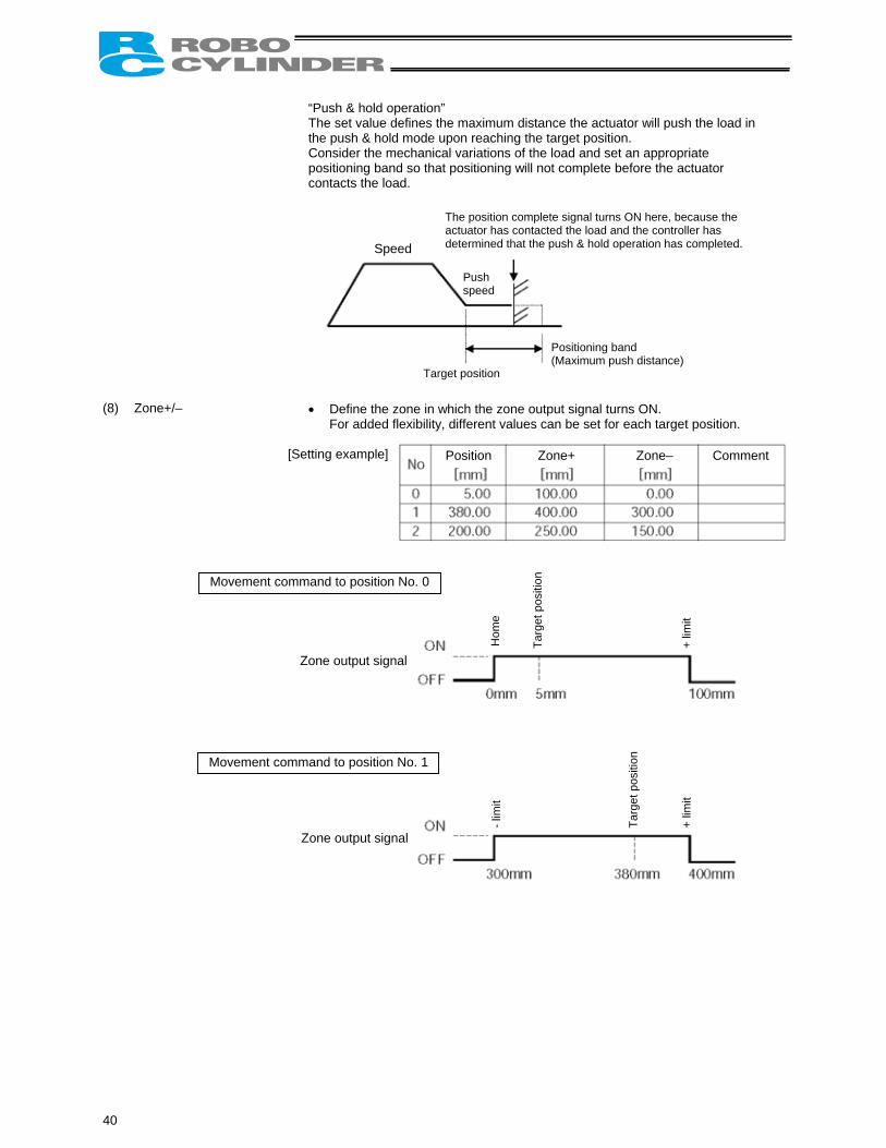
“Push & hold operation” The set value defines the maximum distance the actuator will push the load in the push & hold mode upon reaching the target position. Consider the mechanical variations of the load and set an appropriate positioning band so that positioning will not complete before the actuator contacts the load.
(8) Zone+/–
• Define the zone in wFor added flexibility,
[Setting example]
Movement command to position No. 0
Zone output signal
Movement command to position No. 1
Zone output signal
Speed
40
The position complete signal turns ON here, because the actuator has contacted the load and the controller has
determined that the push & hold operation has completed.Push speed
Positioning band (Maximum push distance)
Target positionhich the zone output signal turns ON. different values can be set for each target position.
Position Zone+ Zone– Comment
Hom
e
Targ
et p
ositi
on
Targ
et p
ositi
on
+ lim
it +
limit
- lim
it
(9) Acceleration/deceleration
mode
• This field is not used for this controller. The factory setting is “0.”
(10) Incremental
• This setting defines whether to use the absolute mode or incremental mode. The factory setting is “0.” 0: Absolute mode 1: Incremental mode
(11) Command mode
• This field is not used for this controller. The factory setting is “0.”
(12) Standstill mode
• This field is not used for this controller. The factory setting is “0.” The power-saving mode to be applied while the actuator is standing by is set by parameter No. 53. The full servo control mode can be selected by setting “4” in this field.
Full servo control mode
The pulse motor is servo-controlled to reduce the holding current (standstill current that flows after completion of positioning). Although the exact degree of current reduction varies depending on the actuator model, load condition, etc., the holding current decreases to approx. one-half to one-fourth. Since the servo remains on, no position deviation occurs. The actual holding current can be checked in the current monitor screen of the PC software. To enable this mode, set “4” in this field.
41
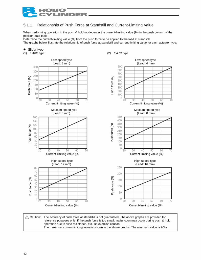
5.1.1 Relationship of Push Force at Standstill and Current-Limiting Value When performing operation in the push & hold mode, enter the current-limiting value (%) in the push column of the position-data table. Determine the current-limiting value (%) from the push force to be applied to the load at standstill. The graphs below illustrate the relationship of push force at standstill and current-limiting value for each actuator type:
Slider type (1) SA6C type (2) SA7C type
Low-speed type Low-speed type (Lead: 3 mm) (Lead: 4 mm)
Medium-speed type Medium-speed type (Lead: 6 mm) (Lead: 8 mm)
High-speed type High-speed type (Lead: 12 mm) (Lead: 16 mm)
Caution: The accuracy of push force at standstill is not guaranteed. The above graphs are provided for reference purposes only. If the push force is too small, malfunction may occur during push & hold operation due to slide resistance, etc., so exercise caution. The maximum current-limiting value is shown in the above graphs. The minimum value is 20%.
Pus
h fo
rce
(N)
Pus
h fo
rce
(N)
Current-limiting value (%) Current-limiting value (%)
Pus
h fo
rce
(N)
Pus
h fo
rce
(N)
Pus
h fo
rce
(N)
Pus
h fo
rce
(N)
Current-limiting value (%) Current-limiting value (%)
Current-limiting value (%) Current-limiting value (%)
42
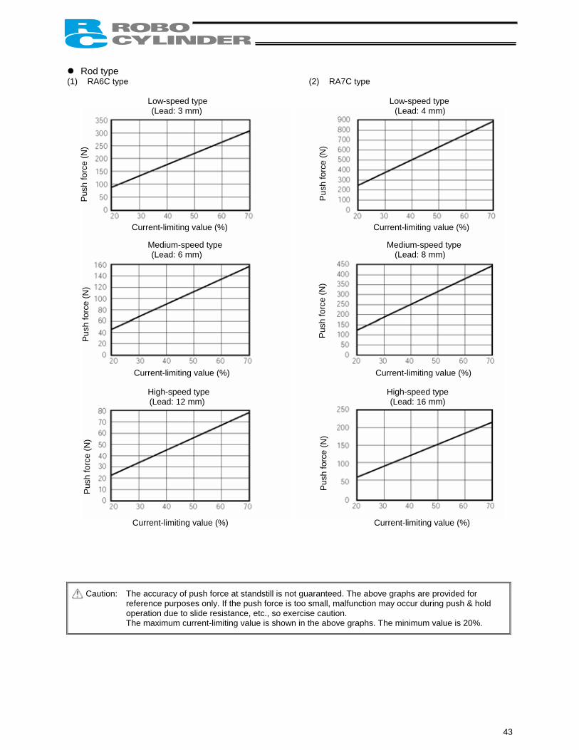
Rod type (1) RA6C type (2) RA7C type
Low-speed type Low-speed type (Lead: 3 mm) (Lead: 4 mm)
Medium-speed type Medium-speed type (Lead: 6 mm) (Lead: 8 mm)
High-speed type High-speed type (Lead: 12 mm) (Lead: 16 mm)
Caution: The accuracy of push force at standstill is not guaranteed. The above graphs are provided for reference purposes only. If the push force is too small, malfunction may occur during push & hold operation due to slide resistance, etc., so exercise caution. The maximum current-limiting value is shown in the above graphs. The minimum value is 20%.
Pus
h fo
rce
(N)
Pus
h fo
rce
(N)
Current-limiting value (%) Current-limiting value (%)
Pus
h fo
rce
(N)
Pus
h fo
rce
(N)
Pus
h fo
rce
(N)
Pus
h fo
rce
(N)
Current-limiting value (%) Current-limiting value (%)
Current-limiting value (%) Current-limiting value (%)
43
5.2 Data Set in the Numerical Specification Mode When the actuator is operated in the numerical specification mode, the position table becomes ineffective. Accordingly, you must specify operation data (target position, speed, acceleration/deceleration, current-limiting value during push & hold operation, positioning band, etc.) directly as numerical values via serial communication. For details, refer to the operation manual for the gateway unit you are using, or the manual on serial communication. 5.3 Explanation of Functions The table below lists the key functions available on ERC2-SE actuators in the position number specification mode and the numerical specification mode, respectively.
44
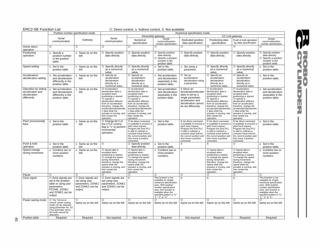
ERC2-SE Function List : Direct control, ∆: Indirect control, X: Not available
Position number specification mode Numerical specification mode DeviceNet gateway CC-Link gateway
Serial communication Gateway Serial
communication Numerical specification
Simple numerical/position
number specification
Dedicated position data specification
Positioning data specification
Push & hold operation by data specification
Simple numerical/position
number specification Home return operation
Positioning operation
∆ Specify a position number in the position table.
∆ Same as on the left
Specify position data directly.
Specify position data directly.
Specify position data directly.
Specify a position number in the position table.
Specify position data directly.
Specify position data directly.
Specify position data directly.
Specify position data directly.
Specify a position number in the position table.
Speed setting ∆ Set in the position table.
∆ Same as on the left
Specify directly as a numerical value.
Specify directly as a numerical value.
∆ Set in the position table.
∆ Set using a parameter.
Specify directly as a numerical value.
Specify directly as a numerical value.
∆ Set in the position table.
Acceleration/ deceleration setting
∆ Set acceleration and deceleration differently in the position table.
∆ Same as on the left
Specify an acceleration/ deceleration directly as a numerical value.
Specify an acceleration/ deceleration directly as a numerical value.
∆ Set acceleration and deceleration separately in the position table.
Set an acceleration/ deceleration using a parameter.
Specify an acceleration/ deceleration directly as a numerical value.
Specify an acceleration/ deceleration directly as a numerical value.
∆ Set in the position table.
Operation by setting acceleration and deceleration differently
∆ Set acceleration and deceleration differently in the position table.
∆ Same as on the left
Acceleration/ deceleration data is accepted when positioning is started. To specify a deceleration different from an acceleration, therefore, change the acceleration/deceleration data while the actuator is moving, and then restart the operation.
Acceleration/ deceleration data is accepted when positioning is started. To specify a deceleration different from an acceleration, therefore, change the acceleration/deceleration data while the actuator is moving, and then restart the operation.
∆ Set acceleration and deceleration separately in the position table.
X Since an acceleration/deceleration is set by a single parameter, acceleration and deceleration cannot be set differently.
Acceleration/ deceleration data is accepted when positioning is started. To specify a deceleration different from an acceleration, therefore, change the acceleration/deceleration data while the actuator is moving, and then restart the operation.
Acceleration/ deceleration data is accepted when positioning is started. To specify a deceleration different from an acceleration, therefore, change the acceleration/deceleration data while the actuator is moving, and then restart the operation.
∆ Set acceleration and deceleration separately in the position table.
Pitch (incremental) feed
∆ Set in the position table.
∆ Same as on the left
Change bit 2 of the CTLF control flag to “1” to perform incremental operation.
X No direct command is available to process a pitch feed request. Program the host PLC to add or subtract a constant travel to/from the current position and then issue a position command.
∆ Set in the position table.
X No direct command is available to process a pitch feed request. Program the host PLC to add or subtract a constant travel to/from the current position and then issue a position command.
X No direct command is available to process a pitch feed request. Program the host PLC to add or subtract a constant travel to/from the current position and then issue a position command.
X No direct command is available to process a pitch feed request. Program the host PLC to add or subtract a constant travel to/from the current position and then issue a position command.
∆ Set in the position table.
Push & hold operation
∆ Set in the position table.
∆ Same as on the left
Specify position data directly.
∆ Set in the position table.
X X ∆ Set in the position table.
Speed change during movement
∆ Combine two or more position numbers.
∆ Same as on the left
Speed data is accepted when positioning is started. To change the speed during movement, therefore, change the speed while the actuator is moving, and then restart the operation.
Speed data is accepted when positioning is started. To change the speed during movement, therefore, change the speed while the actuator is moving, and then restart the operation.
∆ Combine two or more position numbers.
X Speed data is accepted when positioning is started. To change the speed during movement, therefore, change the speed while the actuator is moving, and then restart the operation.
Speed data is accepted when positioning is started. To change the speed during movement, therefore, change the speed while the actuator is moving, and then restart the operation.
∆ Combine two or more position numbers.
Pause Zone signal Zone signals are
set in the position table or using user parameters. PZONE, ZONE1 and ZONE2 can be output.
Zone signals are set using user parameters. ZONE1 and ZONE2 can be output.
Zone signals are set using user parameters. ZONE1 and ZONE2 can be output.
X This function is not available for simple numerical specification axes. With position number specification axes, this function is available when the specified pattern is “0,” “1,” “2” or “4.”
X X X This function is not available for simple numerical specification axes. With position number specification axes, this function is available when the specified pattern is “0,” “1,” “2” or “4.”
Power-saving mode The “full servo control” power-saving mode can be selected using parameter No. 53. (The automatic servo-off mode cannot be selected.)
Same as on the left
Same as on the left
Same as on the left
Same as on the left
Same as on the left
Same as on the left
Same as on the left
Same as on the left
Position table Required Required Not required Not required Required Not required Required Required Required 45
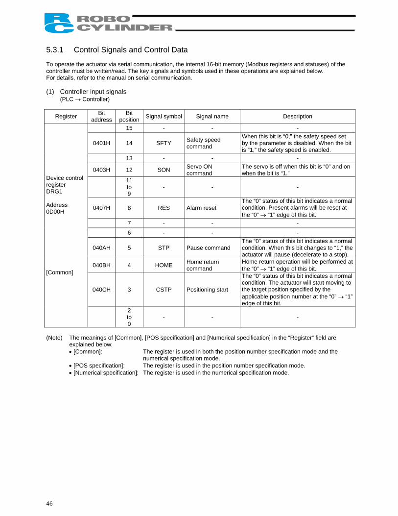
5.3.1 Control Signals and Control Data To operate the actuator via serial communication, the internal 16-bit memory (Modbus registers and statuses) of the controller must be written/read. The key signals and symbols used in these operations are explained below. For details, refer to the manual on serial communication. (1) Controller input signals
(PLC → Controller)
Register Bit address
Bit position Signal symbol Signal name Description
15 - - -
0401H 14 SFTY Safety speed command
When this bit is “0,” the safety speed set by the parameter is disabled. When the bit is “1,” the safety speed is enabled.
13 - - -
0403H 12 SON Servo ON command
The servo is off when this bit is “0” and on when the bit is “1.”
11 to 9
- - -
0407H 8 RES Alarm reset The “0” status of this bit indicates a normal condition. Present alarms will be reset at the “0” → “1” edge of this bit.
7 - - - 6 - - -
040AH 5 STP Pause command The “0” status of this bit indicates a normal condition. When this bit changes to “1,” the actuator will pause (decelerate to a stop).
040BH 4 HOME Home return command
Home return operation will be performed at the “0” → “1” edge of this bit.
040CH 3 CSTP Positioning start
The “0” status of this bit indicates a normal condition. The actuator will start moving to the target position specified by the applicable position number at the “0” → “1” edge of this bit.
Device control register DRG1 Address 0D00H [Common]
2 to 0
- - -
(Note) The meanings of [Common], [POS specification] and [Numerical specification] in the “Register” field are
explained below: • [Common]: The register is used in both the position number specification mode and the
numerical specification mode. • [POS specification]: The register is used in the position number specification mode. • [Numerical specification]: The register is used in the numerical specification mode.
46
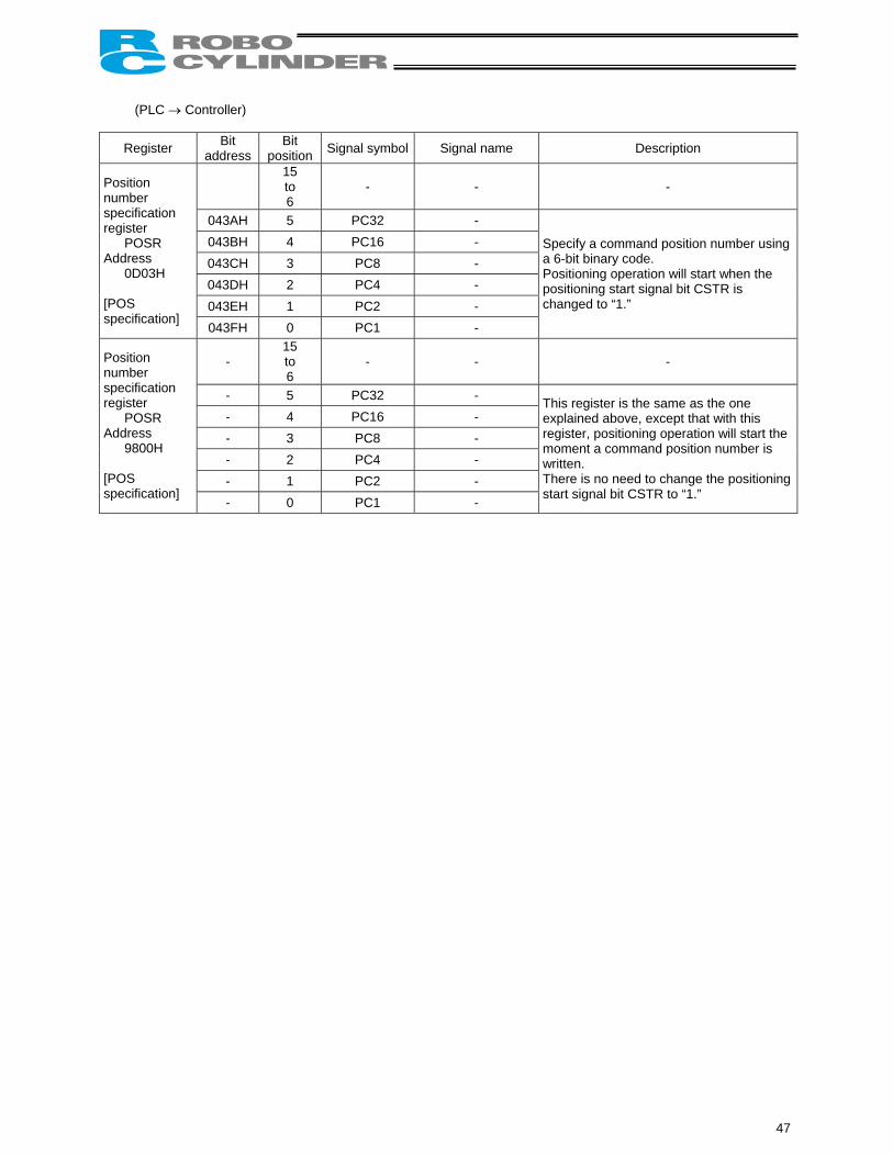
(PLC → Controller)
Register Bit address
Bit position Signal symbol Signal name Description
15 to 6
- - -
043AH 5 PC32 - 043BH 4 PC16 - 043CH 3 PC8 - 043DH 2 PC4 - 043EH 1 PC2 -
Position number specification register
POSR Address
0D03H [POS specification]
043FH 0 PC1 -
Specify a command position number using a 6-bit binary code. Positioning operation will start when the positioning start signal bit CSTR is changed to “1.”
- 15 to 6
- - -
- 5 PC32 - - 4 PC16 - - 3 PC8 - - 2 PC4 - - 1 PC2 -
Position number specification register
POSR Address
9800H [POS specification]
- 0 PC1 -
This register is the same as the one explained above, except that with this register, positioning operation will start the moment a command position number is written. There is no need to change the positioning start signal bit CSTR to “1.”
47
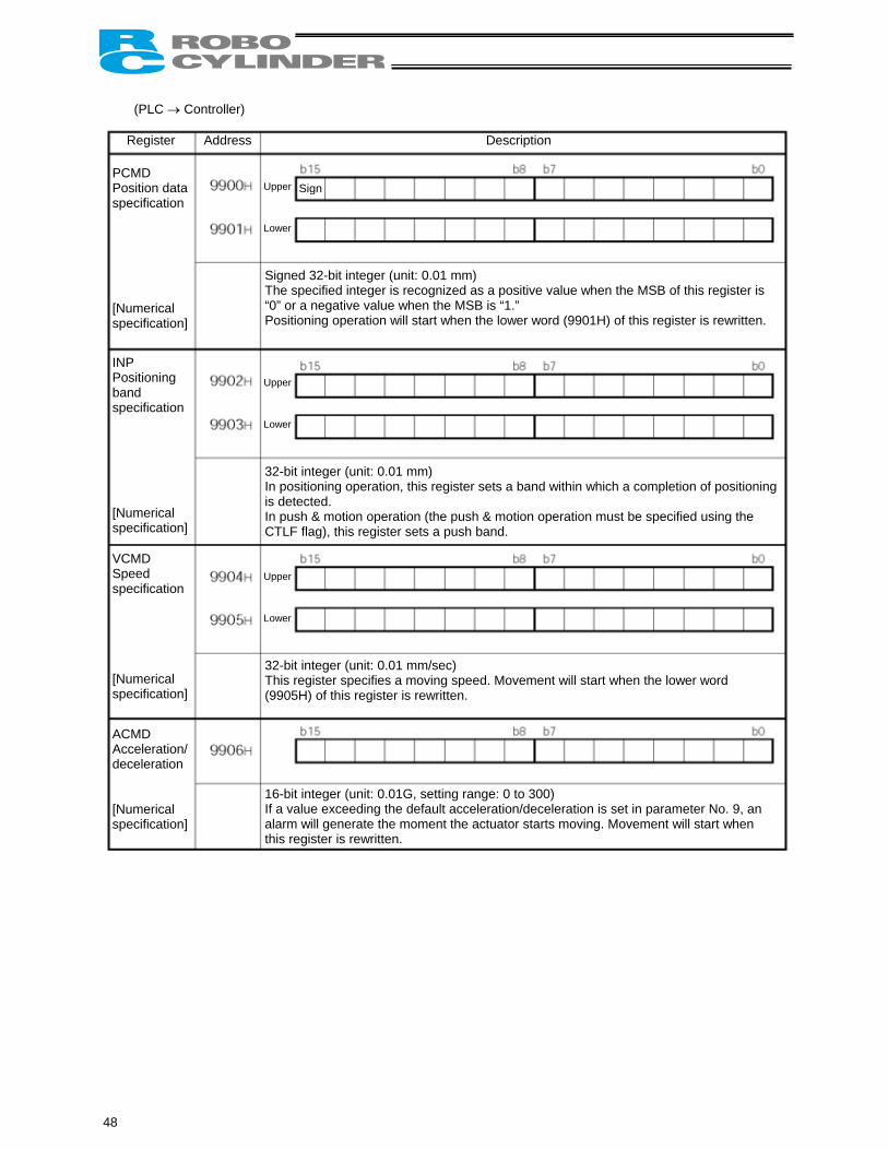
(PLC → Controller) Register Address Description
Upper Lower
S
Signed 32-bit integer (unit: 0.01 mm) The specified integer is recognized as a positive value when the MSB of this register is “0” or a negative value when the MSB is “1.” Positioning operation will start when the lower word (9901H) of this register is rewritten.
48
PCMD Position data specification [Numerical specification]
Upper Lower
32-bit integer (unit: 0.01 mm) In positioning operation, this register sets a band within which a completion of positioning is detected. In push & motion operation (the push & motion operation must be specified using the
INP Positioning band specification [Numerical specification]
VCMD Speed specification [Numerical specification]
ACMD Acceleration/deceleration [Numerical specification]
Upper Lower
CTLF
32-bit This re(9905H
1Iat
ign
flag), this register sets a push band.
integer (unit: 0.01 mm/sec) gister specifies a moving speed. Movement will start when the lower word ) of this register is rewritten.
6-bit integer (unit: 0.01G, setting range: 0 to 300) f a value exceeding the default acceleration/deceleration is set in parameter No. 9, an larm will generate the moment the actuator starts moving. Movement will start when his register is rewritten.
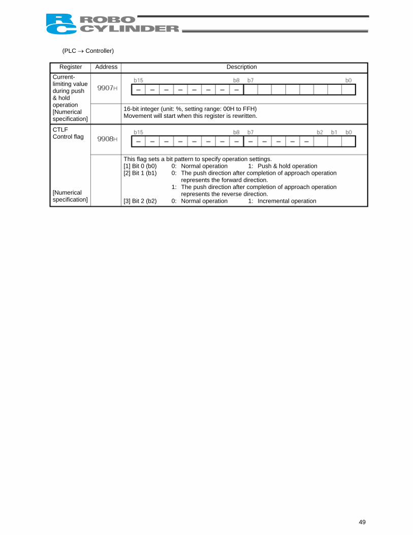
(PLC → Controller)
Register Address Description
Cld&o[s
CC [s
16-bit integer (unit: %, setting range: 00H to FFH) Movement will start when this register is rewritten.
urrent-imiting value uring push hold peration Numerical
pecification]T[[
TLF ontrol flag
Numerical pecification]
his flag sets a bit pattern to specify operation settings. 1] Bit 0 (b0) 0: Normal operation 1: Push & hold operation 2] Bit 1 (b1) 0: The push direction after completion of approach operation
represents the forward direction. 1: The push direction after completion of approach operation
represents the reverse direction. [3] Bit 2 (b2) 0: Normal operation 1: Incremental operation
49
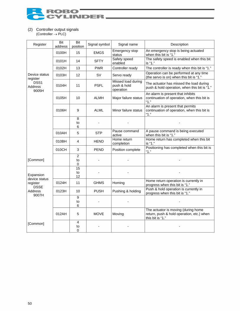
(2) Controller output signals
(Controller → PLC)
Register Bit address
Bit position Signal symbol Signal name Description
0100H 15 EMGS Emergency stop status
An emergency stop is being actuated when this bit is “1.”
0101H 14 SFTY Safety speed enabled
The safety speed is enabled when this bit is “1.”
0102H 13 PWR Controller ready The controller is ready when this bit is “1.”
0103H 12 SV Servo ready Operation can be performed at any time (the servo is on) when this bit is “1.”
0104H 11 PSFL Missed load during push & hold operation
The actuator has missed the load during push & hold operation, when this bit is “1.”
0105H 10 ALMH Major failure status An alarm is present that inhibits continuation of operation, when this bit is “1.”
0106H 9 ALML Minor failure status An alarm is present that permits continuation of operation, when this bit is “1.”
8 to 6
- - -
010AH 5 STP Pause command active
A pause command is being executed when this bit is “1.”
010BH 4 HEND Home return completion
Home return has completed when this bit is “1.”
010CH 3 PEND Position complete Positioning has completed when this bit is “1.”
Device status register
DSS1 Address
9005H [Common]
2 to 0
- - -
15 to 12
- - -
0124H 11 GHMS Homing Home return operation is currently in progress when this bit is “1.”
0123H 10 PUSH Pushing & holding Push & hold operation is currently in progress when this bit is “1.”
9 to 6
- - -
012AH 5 MOVE Moving The actuator is moving (during home return, push & hold operation, etc.) when this bit is “1.”
Expansion device status register
DSSE Address
9007H [Common]
4 to 0
- - -
50
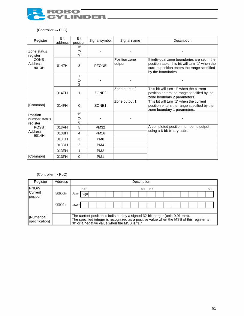
(Controller → PLC)
Register Bit address
Bit position Signal symbol Signal name Description
15 to 9
- - -
0147H 8 PZONE
Position zone output
If individual zone boundaries are set in the position table, this bit will turn “1” when the current position enters the range specified by the boundaries.
7 to 2
- - -
014EH 1 ZONE2 Zone output 2 This bit will turn “1” when the current
position enters the range specified by the zone boundary 2 parameters.
Zone status register
ZONS Address
9013H [Common] 014FH 0 ZONE1
Zone output 1 This bit will turn “1” when the current position enters the range specified by the zone boundary 1 parameters.
15 to 6
- - -
013AH 5 PM32 013BH 4 PM16 013CH 3 PM8 013DH 2 PM4 013EH 1 PM2
Position number status register
POSS Address
9014H [Common] 013FH 0 PM1
A completed position number is output using a 6-bit binary code.
(Controller → PLC) P C p [ s
Register Address Description
TT
Upper Lower
NOW urrent osition
Numerical pecification]
“he current position is indicated by a signed 32-bit integer (unit: 0.01 mm). he specified integer is recognized as a positive value when the MSB of this register is
0” or a negative value when the MSB is “1.”
Sign
51
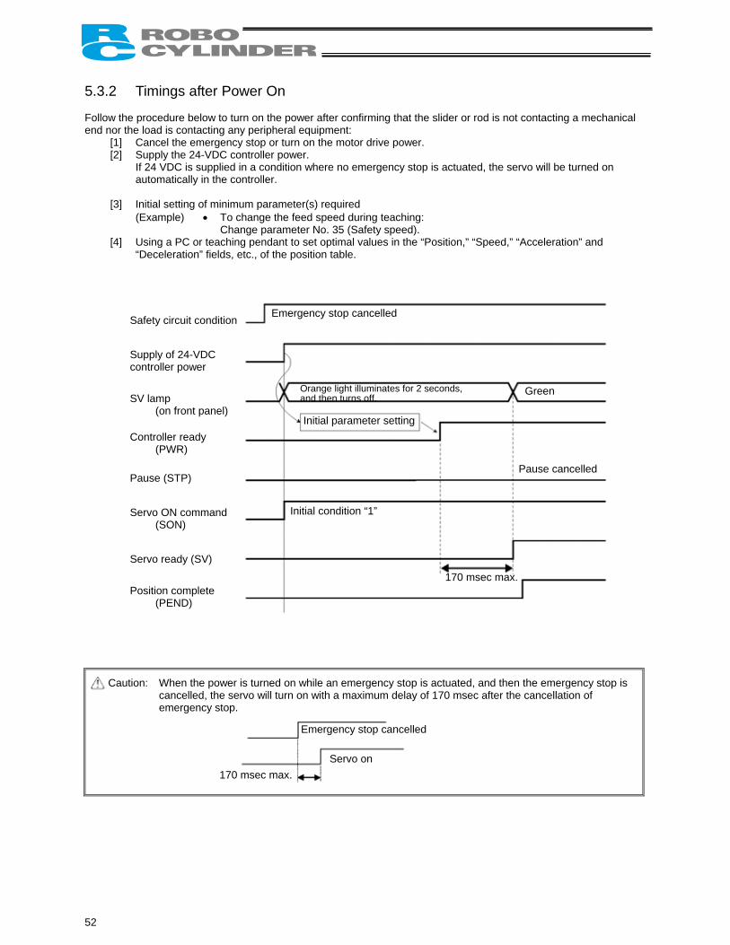
5.3.2 Timings after Power On Follow the procedure below to turn on the power after confirming that the slider or rod is not contacting a mechanical end nor the load is contacting any peripheral equipment:
[1] Cancel the emergency stop or turn on the motor drive power. [2] Supply the 24-VDC controller power.
If 24 VDC is supplied in a condition where no emergency stop is actuated, the servo will be turned on automatically in the controller.
[3] Initial setting of minimum parameter(s) required
(Example) • To change the feed speed during teaching: Change parameter No. 35 (Safety speed).
[4] Using a PC or teaching pendant to set optimal values in the “Position,” “Speed,” “Acceleration” and “Deceleration” fields, etc., of the position table.
Caut
S Sc S
C
P S
S
P
Emergency stop cancelled
O a
Green
Initial parameter setting
Initial condition “1”
Pause cancelled
170 msec max.
52
afety circuit condition
upply of 24-VDC ontroller power
V lamp (on front panel)
ontroller ready (PWR)
ause (STP)
ervo ON command (SON)
ervo ready (SV)
osition complete (PEND)
ion: When the power is turned on wcancelled, the servo will turn oemergency stop.
170 msec max.
range light illuminates for 2 seconds,nd then turns off.
hile an emergency stop is actuated, and then the emergency stop is n with a maximum delay of 170 msec after the cancellation of
Emergency stop cancelled
Servo on
Warning: Since a pulse motor is used as the driving motor, the excited phase will be detected when the servo is turned on for the first time after the power on. Accordingly, the actuator must be able to move when the servo is turned on. If the slider or rod is contacting a mechanical end or the load is contacting any peripheral equipment, the excited phase will not be detected correctly and a malfunction or excitation detection error may result. In such a case, move the actuator by hand to a position where it can move freely, before turning on the servo. If the actuator is equipped with a brake, the brake release switch must be turned on to forcibly release the brake. When operating the brake release switch, be careful not to let your hand pinched, or the robot hand or load damaged, by the actuator dropping suddenly due to its dead weight. If the actuator cannot be moved by hand, one option is to change parameter No. 28 (Default direction of excited-phase signal detection). If you wish to change this parameter, consult IAI in advance.
Controller ready (PWR) This signal indicates whether the controller can be controlled externally. When the signal bit is “0,” the controller is busy. When the bit is “1,” the controller is ready. The controller does not become busy in normal conditions of use.
Servo ON command (SON) The servo will turn on when this signal bit turns “1.” Use this signal if servo on/off must be controlled to provide a safety circuit for the entire system on the PLC side.
Servo ready (SV) This is a monitor signal indicating, following the input of a servo ON command (SON), that the servo is on and the motor can be driven. The “1”/“0” status of this signal bit is synchronized with the on (green light)/off status of the SV lamp provided on the front panel.
53
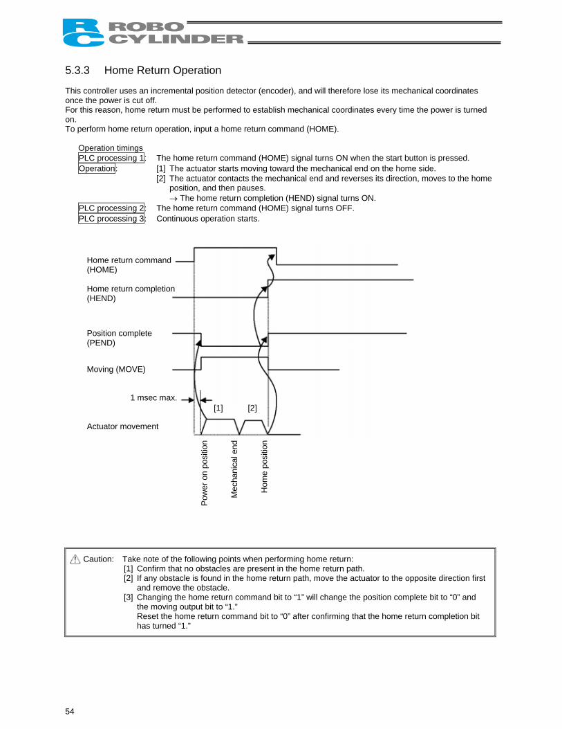
5.3.3 Home Return Operation This controller uses an incremental position detector (encoder), and will therefore lose its mechanical coordinates once the power is cut off. For this reason, home return must be performed to establish mechanical coordinates every time the power is turned on. To perform home return operation, input a home return command (HOME).
Operation timings PLC processing 1: The home return command (HOME) signal turns ON when the start button is pressed. Operation: [1] The actuator starts moving toward the mechanical end on the home side.
[2] The actuator contacts the mechanical end and reverses its direction, moves to the home position, and then pauses. → The home return completion (HEND) signal turns ON.
PLC processing 2: The home return command (HOME) signal turns OFF. PLC processing 3: Continuous operation starts.
C
[1] [2]
54
1 msec max.
Home return command (HOME) Home return completion (HEND) Position complete (PEND) Moving (MOVE) Actuator movement
aution: Take note of the following points when p[1] Confirm that no obstacles are prese[2] If any obstacle is found in the home
and remove the obstacle. [3] Changing the home return comman
the moving output bit to “1.” Reset the home return command bithas turned “1.”
Pow
er o
n po
sitio
n
Mec
hani
cal e
nd n
erforming home return: nt in the home return path. return path, move the actuator to the opposite direction first
d bit to “1” will change the position complete bit to “0” and
to “0” after confirming that the home return completion bit
Hom
e po
sitio
Home return command (HOME) Home return operation will start upon detection of the “0” → “1” edge of this signal bit. When home return is completed, the home return completion (HEND) signal will be output. The HOME signal can be input as many time as desired even after home return has been completed once. (Note) Even if home return is not performed after the power has been turned on, the actuator will automatically
perform home return operation as part of the first positioning operation (CSTR signal).
Home return completion (HEND) This signal bit is “0” immediately after the power has been turned on. It will turn “1” at the following timings: [1] Home return operation initiated by the HOME signal has completed. [2] Home return operation performed as part of the first positioning operation initiated by the CSTR signal has
completed. Once turning “1,” this signal bit will not turn “0” until the input power is cut off or the HOME signal is input again. Use this signal as an interlock signal to confirm that the actuator is safe to perform home return.
55
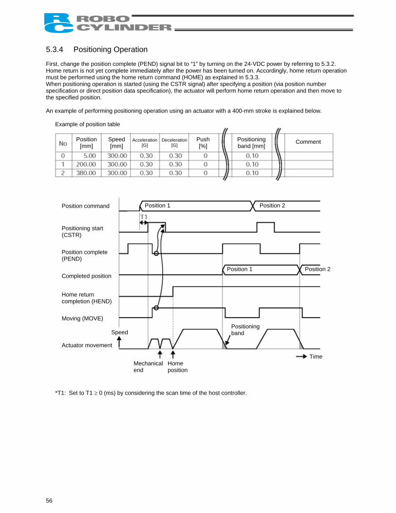
5.3.4 Positioning Operation First, change the position complete (PEND) signal bit to “1” by turning on the 24-VDC power by referring to 5.3.2. Home return is not yet complete immediately after the power has been turned on. Accordingly, home return operation must be performed using the home return command (HOME) as explained in 5.3.3. When positioning operation is started (using the CSTR signal) after specifying a position (via position number specification or direct position data specification), the actuator will perform home return operation and then move to the specified position. An example of performing positioning operation using an actuator with a 400-mm stroke is explained below.
Example of position table
Comment Position [mm]
Speed [mm]
Acceleration [G]
Deceleration[G]
Push [%]
Positioning band [mm]
peed
Position 1 Position 2
Position 1 Position 2
Positioning band
*T1
56
Position command Positioning start (CSTR) Position complete (PEND) Completed position Home return completion (HEND) Moving (MOVE)
S
Actuator movement
end position Mechanical Home
Time
: Set to T1 ≥ 0 (ms) by considering the scan time of the host controller.
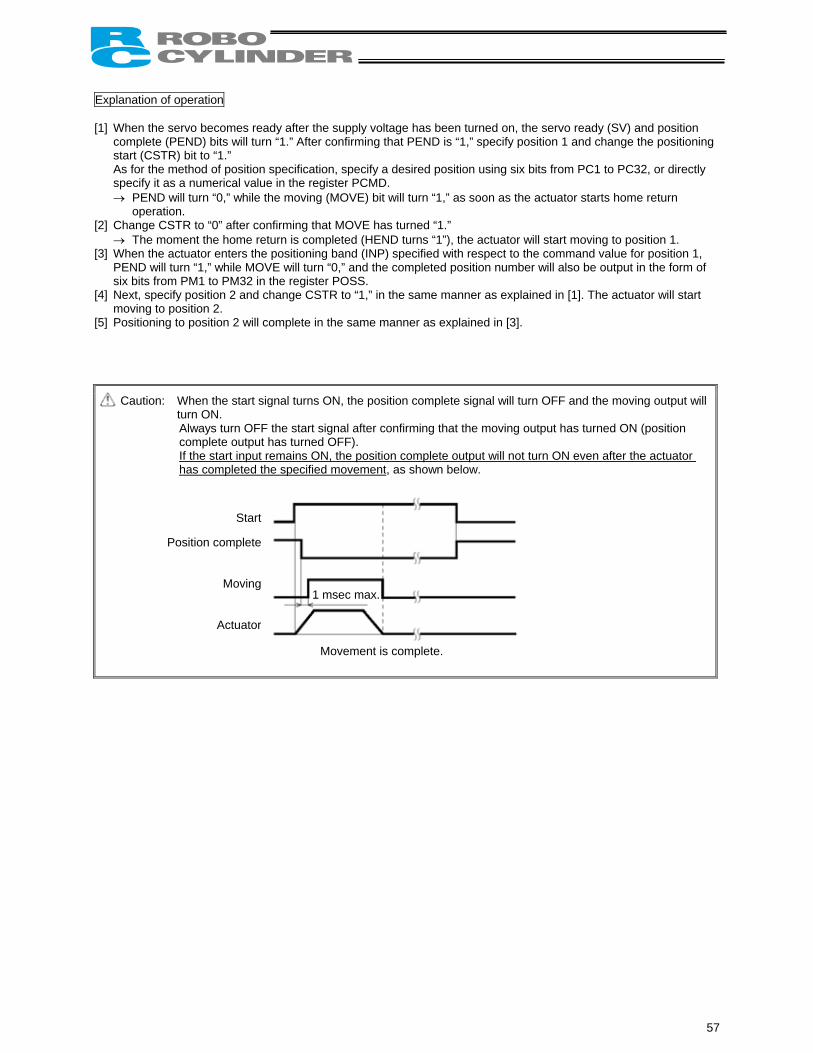
Explanation of operation [1] When the servo becomes ready after the supply voltage has been turned on, the servo ready (SV) and position
complete (PEND) bits will turn “1.” After confirming that PEND is “1,” specify position 1 and change the positioning start (CSTR) bit to “1.” As for the method of position specification, specify a desired position using six bits from PC1 to PC32, or directly specify it as a numerical value in the register PCMD. → PEND will turn “0,” while the moving (MOVE) bit will turn “1,” as soon as the actuator starts home return
operation. [2] Change CSTR to “0” after confirming that MOVE has turned “1.”
→ The moment the home return is completed (HEND turns “1”), the actuator will start moving to position 1. [3] When the actuator enters the positioning band (INP) specified with respect to the command value for position 1,
PEND will turn “1,” while MOVE will turn “0,” and the completed position number will also be output in the form of six bits from PM1 to PM32 in the register POSS.
[4] Next, specify position 2 and change CSTR to “1,” in the same manner as explained in [1]. The actuator will start moving to position 2.
[5] Positioning to position 2 will complete in the same manner as explained in [3].
Caution: When the start signal turns ON, the position complete signal will turn OFF and the moving output will turn ON. Always turn OFF the start signal after confirming that the moving output has turned ON (position complete output has turned OFF). If the start input remains ON, the position complete output will not turn ON even after the actuator has completed the specified movement, as shown below.
Movement is complete.
Start
Position complete
Moving
Actuator
1 msec max.
57
Positioning start (CSTR) Upon detecting the “0” → “1” leading edge of this signal bit, the controller will read the target position number specified by a binary code consisting of six bits from PC1 to PC32 (in the position number specification register) and cause the actuator to move to the target position of the corresponding position data. Before positioning is performed, however, the target position, speed and other operation data must be set in the position table using a PC/teaching pendant. If this command is issued when home return operation has never been performed (= the HEND output signal bit is “0”) after the power was turned on, the actuator will perform home return operation automatically and then move to the target position.
Moving (MOVE) This signal is output while the actuator is moving (also during home return, push & hold operation and jogging) with the servo turned on. Use this signal together with PEND to determine the actuator status from the PLC side. This signal bit will turn “0” upon completion of positioning, upon completion of home return, after push & hold completion judgment during push & hold operation, and during pause.
Command position number (PC1 to PC32) When a moving command is executed at the “0” → “1” edge of the CSTR signal bit, a binary code specified by six signal bits from PC1 to PC32 will be read as the command position number.
Completed position number (PM1 to PM32) These signals can be used to check the completed position number effective when the PEND signal bit has turned “1.” These signals are output as a binary code in the position number status register. Immediately after the power has been turned on, all signal bits from PM1 to PM32 are “0.” All bits remain “0” while the actuator is moving. As evident from the above explanation, these signals are output only upon completion of positioning. Although all signal bits will turn “0” when the servo is turned off or an emergency stop is actuated, the bits will return to “1” when the servo is turned on again, if the actuator is inside the positioning band with respect to the target position. If the actuator is not inside the positioning band, the signal bits will remain “0.” These bits will also turn “1” when the push & hold completion judgment signal has turned ON, or the actuator has missed the load, during push & hold operation.
58

Position complete (PEND) This signal indicates that the target position has been reached, and turns ON only when the following conditions are satisfied:
[1] The servo ready (SV) bit is “1” AND [2] the current position has reached the positioning band before each target position OR [3] the actuator has not missed the load during push & hold operation.
Use this signal as a trigger signal to operate peripheral equipment upon reaching the target position. Increasing the positioning band will allow a command to be issued more quickly to peripheral equipment, which will effectively shorten the tact time of the entire system. When the servo turns on after the power on, the current position will become the target position. As a result, this signal bit will turn “1.” It will turn “0” if positioning operation is started thereafter with the CSTR signal bit changing to “1.” (Note) If the servo is turned off or an emergency stop is actuated while the actuator is stopped at the target position,
PEND will change to “0.” When the servo is turned on again, PEND will return to “1” if the actuator is inside the positioning band. If CSTR remains “1,” PEND will not become “1” even if the current position is inside the positioning band. It will turn “1” only after CSTR has turned “0.”
The position complete signal turns ON here.
Target position
Speed
Travel
Time
Positioning band
59
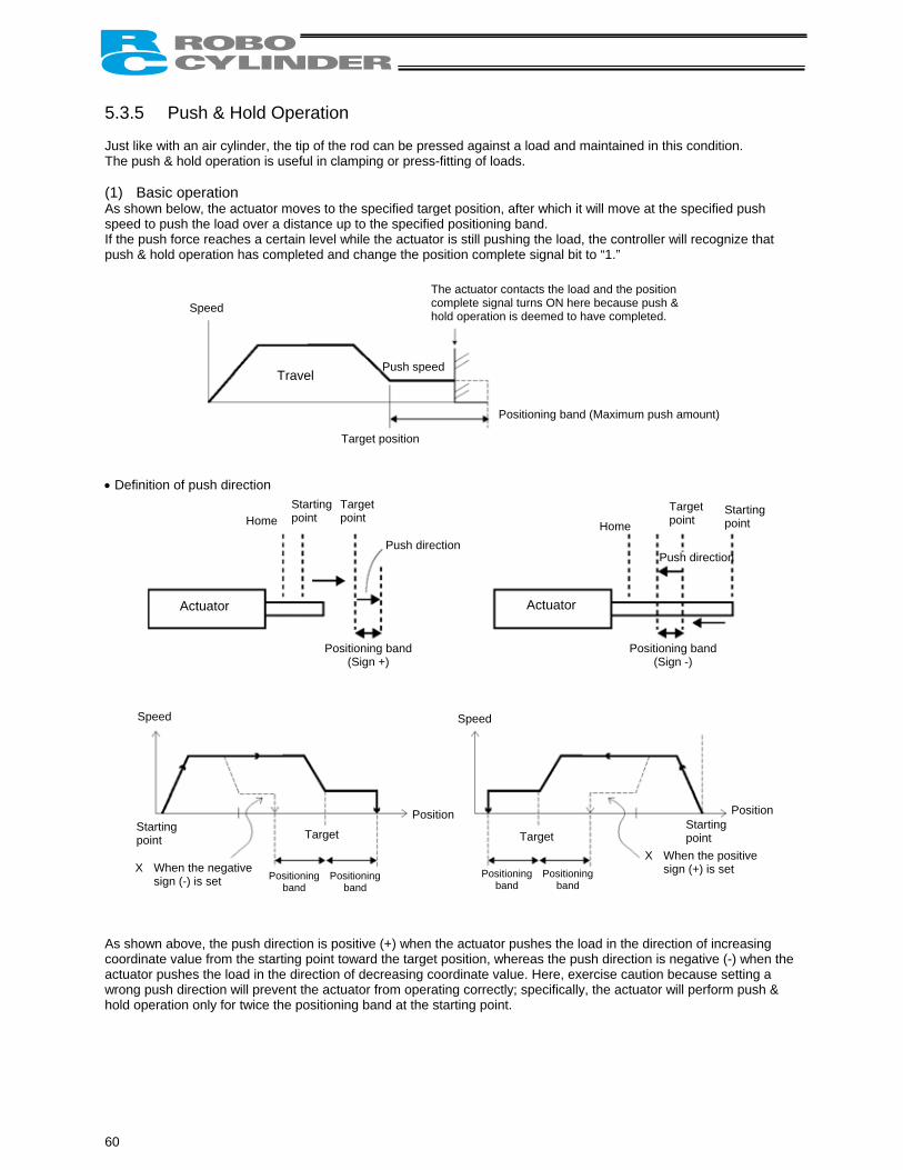
5.3.5 Push & Hold Operation Just like with an air cylinder, the tip of the rod can be pressed against a load and maintained in this condition. The push & hold operation is useful in clamping or press-fitting of loads. (1) Basic operation As shown below, the actuator moves to the specified target position, after which it will move at the specified push speed to push the load over a distance up to the specified positioning band. If the push force reaches a certain level while the actuator is still pushing the load, the controller will recognize that push & hold operation has completed and change the position complete signal bit to “1.” • Definition of push direction
Target position
Speed
Travel
Positioning band (Maximum push amount)
The actuator contacts the load and the position complete signal turns ON here because push & hold operation is deemed to have completed.
Push speed
Actuator Actuator
Home Starting point
Home Starting point
Positioning band (Sign +)
Push direction
Positioning band (Sign -)
sign (-) is set
Position
band band band band
Push direction
Target point
Target point
Speed Speed
X When the negative
Target Target
Position
X When the positive sign (+) is set Positioning Positioning Positioning Positioning
Starting point
Starting point
As shown above, the push direction is positive (+) when the actuator pushes the load in the direction of increasing coordinate value from the starting point toward the target position, whereas the push direction is negative (-) when the actuator pushes the load in the direction of decreasing coordinate value. Here, exercise caution because setting a wrong push direction will prevent the actuator from operating correctly; specifically, the actuator will perform push & hold operation only for twice the positioning band at the starting point.
60
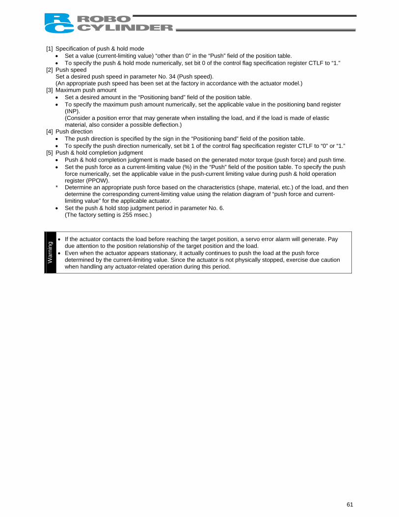
[1] Specification of push & hold mode
• Set a value (current-limiting value) “other than 0” in the “Push” field of the position table. • To specify the push & hold mode numerically, set bit 0 of the control flag specification register CTLF to “1.”
[2] Push speed Set a desired push speed in parameter No. 34 (Push speed). (An appropriate push speed has been set at the factory in accordance with the actuator model.)
[3] Maximum push amount • Set a desired amount in the “Positioning band” field of the position table. • To specify the maximum push amount numerically, set the applicable value in the positioning band register
(INP). (Consider a position error that may generate when installing the load, and if the load is made of elastic material, also consider a possible deflection.)
[4] Push direction • The push direction is specified by the sign in the “Positioning band” field of the position table. • To specify the push direction numerically, set bit 1 of the control flag specification register CTLF to “0” or “1.”
[5] Push & hold completion judgment • Push & hold completion judgment is made based on the generated motor torque (push force) and push time. • Set the push force as a current-limiting value (%) in the “Push” field of the position table. To specify the push
force numerically, set the applicable value in the push-current limiting value during push & hold operation register (PPOW).
* Determine an appropriate push force based on the characteristics (shape, material, etc.) of the load, and then determine the corresponding current-limiting value using the relation diagram of “push force and current-limiting value” for the applicable actuator.
• Set the push & hold stop judgment period in parameter No. 6. (The factory setting is 255 msec.)
War
ning
• If the actuator contacts the load before reaching the target position, a servo error alarm will generate. Pay due attention to the position relationship of the target position and the load.
• Even when the actuator appears stationary, it actually continues to push the load at the push force determined by the current-limiting value. Since the actuator is not physically stopped, exercise due caution when handling any actuator-related operation during this period.
61
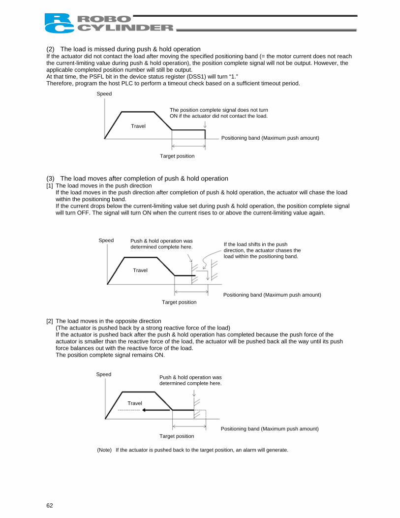
(2) The load is missed during push & hold operation If the actuator did not contact the load after moving the specified positioning band (= the motor current does not reach the current-limiting value during push & hold operation), the position complete signal will not be output. However, the applicable completed position number will still be output. At that time, the PSFL bit in the device status register (DSS1) will turn “1.” Therefore, program the host PLC to perform a timeout check based on a sufficient timeout period. (3) The load moves after completion of push & hold operation [1] The load moves in the push direction
If the load moves in the push direction after completion of push & hold operation, the actuator will chase the load within the positioning band. If the current drops below the current-limiting value set during push & hold operation, the position complete signal will turn OFF. The signal will turn ON when the current rises to or above the current-limiting value again.
[2] The load moves in the opposite direction
(The actuator is pushed back by a strong reactive force of the load) If the actuator is pushed back after the push & hold operation has completed because the push force of the actuator is smaller than the reactive force of the load, the actuator will be pushed back all the way until its push force balances out with the reactive force of the load. The position complete signal remains ON.
Speed
Travel
Target position
Positioning band (Maximum push amount)
The position complete signal does not turn ON if the actuator did not contact the load.
Speed
Travel
Target position Positioning band (Maximum push amount)
Push & hold operation was determined complete here. If the load shifts in the push
direction, the actuator chases the load within the positioning band.
Speed
Positioning band (Maximum push amount)
(Note)
Target position
Push & hold operation was determined complete here.
Travel
62
If the actuator is pushed back to the target position, an alarm will generate.
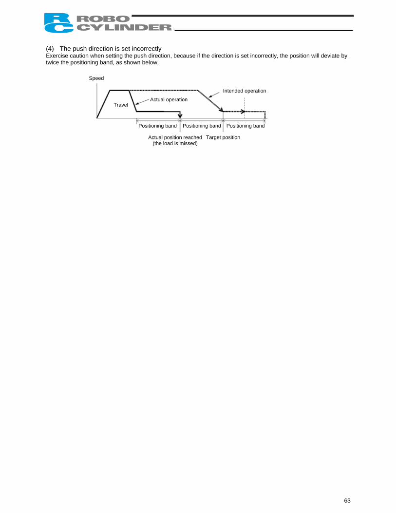
(4) The push direction is set incorrectly Exercise caution when setting the push direction, because if the direction is set incorrectly, the position will deviate by twice the positioning band, as shown below. Speed
Target position
Positioning band
Travel
Positioning band Positioning band
Actual operation
Intended operation
Actual position reached (the load is missed)
63
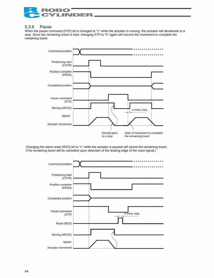
5.3.6 Pause When the pause command (STP) bit is changed to “1” while the actuator is moving, the actuator will decelerate to a stop. Since the remaining travel is held, changing STP to “0” again will resume the movement to complete the remaining travel. Changing the ala (T
C
C
A
4 msec max.
he remaining tr
C
C
A
64
ommand position
Positioning start(CSTR)
Position complete(PEND)
ompleted position
Pause command(STP)
Moving (MOVE)
ctuator movement
Speed
rm reset (RES) bit to “1” w
Start of movement to complete the remaining travel
hile the actuavel will be cancelled upon detection o
Decelerationto a stop
ator is paused will cancel the remaining travel. f the leading edge of the reset signal.)
4 msec max.
ommand position
Positioning start(CSTR)
Position complete(PEND)
ompleted position
Pause command(STP)
Reset (RES)
Moving (MOVE)
ctuator movement
Speed
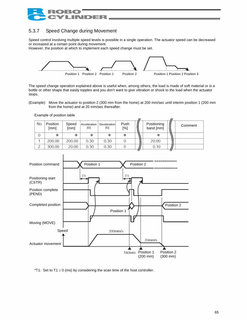
5.3.7 Speed Change during Movement Speed control involving multiple speed levels is possible in a single operation. The actuator speed can be decreased or increased at a certain point during movement. However, the position at which to implement each speed change must be set.
Position 1 Position 2 Position 1 Position 2 Position 1 Position 2 Position 3
The speed change operation explained above is useful when, among others, the load is made of soft material or is a bottle or other shape that easily topples and you don’t want to give vibration or shock to the load when the actuator stops. (Example) Move the actuator to position 2 (300 mm from the home) at 200 mm/sec until interim position 1 (200 mm
from the home) and at 20 mm/sec thereafter.
Example of position table Comment Position
[mm] Speed [mm]
Acceleration [G]
Deceleration[G]
Push [%]
Positioning band [mm]
P
P
( P
(
C
M
A
eed
Position 1 Position 2
Position 1 Position 2
R)
osition command
ositioning start CST
osition complete PEND)
ompleted position
oving (MOVE)
ctuator movement
Sp
Position 1 (200 mm)
Position 2 (300 mm)
*T1: Set to T1 ≥ 0 (ms) by considering the scan time of the host controller.
65
(Note) If a pause command is issued while home return is in progress, the movement command will be held if the
actuator has not yet contacted the mechanical end. If the actuator has already contacted the mechanical end and reversed, home return will be performed again from the beginning.
Alarm reset (RES)
Alarms will be reset at the “0” → “1” leading edge of this signal bit. If any alarm remains whose cause is not yet removed, the same alarm will generate again. If an alarm reset is performed while the actuator is paused, the remaining travel will be cancelled.
Caution: [1] When the start (CSTR) signal is changed to “1,” the position complete (PEND) bit will turn “1,” while the moving (MOVE) bit will turn “1.” Change the start (CSTR) signal bit to “1” after confirming that the moving (MOVE) signal bit has turned “1.”
[2] Setting a wider positioning band for position 1 will allow for smooth speed change without causing the actuator to stop.
66
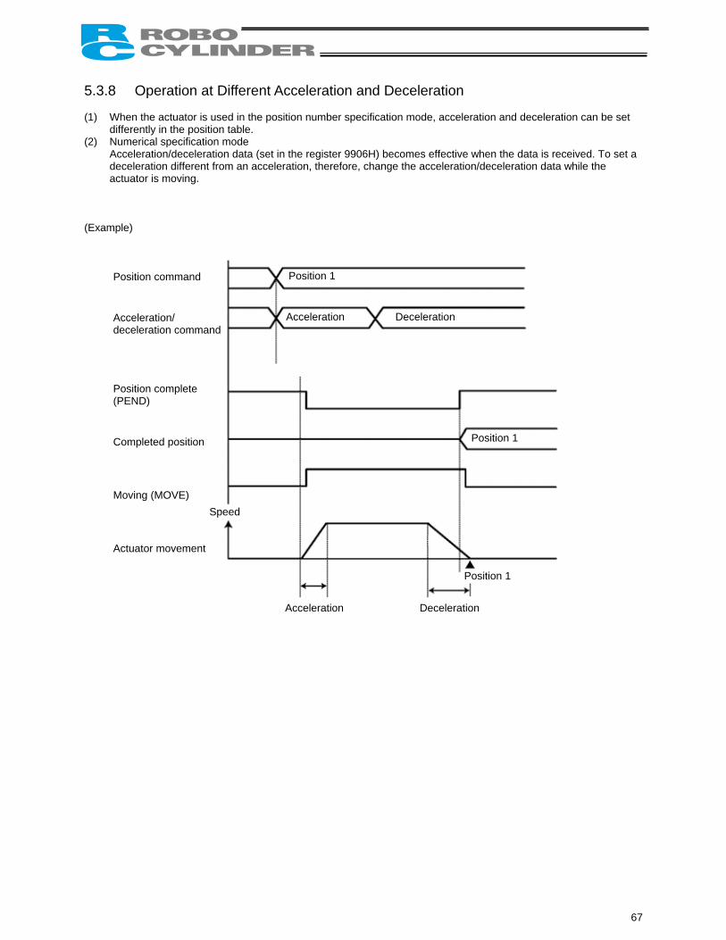
5.3.8 Operation at Different Acceleration and Deceleration (1) When the actuator is used in the position number specification mode, acceleration and deceleration can be set
differently in the position table. (2) Numerical specification mode
Acceleration/deceleration data (set in the register 9906H) becomes effective when the data is received. To set a deceleration different from an acceleration, therefore, change the acceleration/deceleration data while the actuator is moving.
(Example)
ed
Position 1
Acceleration Deceleration
Position 1
Position command Acceleration/ deceleration command Position complete (PEND)
Completed position Moving (MOVE)
Spe
Actuator movement
Position 1
Acceleration Deceleration
67
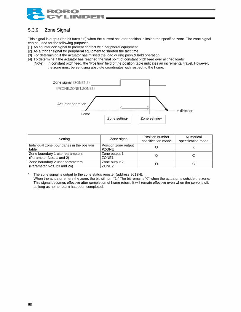
5.3.9 Zone Signal This signal is output (the bit turns “1”) when the current actuator position is inside the specified zone. The zone signal can be used for the following purposes: [1] As an interlock signal to prevent contact with peripheral equipment [2] As a trigger signal for peripheral equipment to shorten the tact time [3] For determining if the actuator has missed the load during push & hold operation [4] To determine if the actuator has reached the final point of constant pitch feed over aligned loads
(Note) In constant pitch feed, the “Position” field of the position table indicates an incremental travel. However, the zone must be set using absolute coordinates with respect to the home.
Z
Individual zone table Zone boundary (Parameter NosZone boundary (Parameter Nos
* The zone sig
When the acThis signal bas long as ho
68
one signal
bo
1 u. 12 u. 2
natuaecm
Actuator operation
Home Zone setting- Zone setting+
+ direction
Setting Zone signal Position number specification mode
Numerical specification mode
undaries in the position Position zone output PZONE x
ser parameters and 2)
Zone output 1 ZONE1
ser parameters 3 and 24)
Zone output 2 ZONE2
l is output to the zone status register (address 9013H). tor enters the zone, the bit will turn “1.” The bit remains “0” when the actuator is outside the zone.
omes effective after completion of home return. It will remain effective even when the servo is off, e return has been completed.
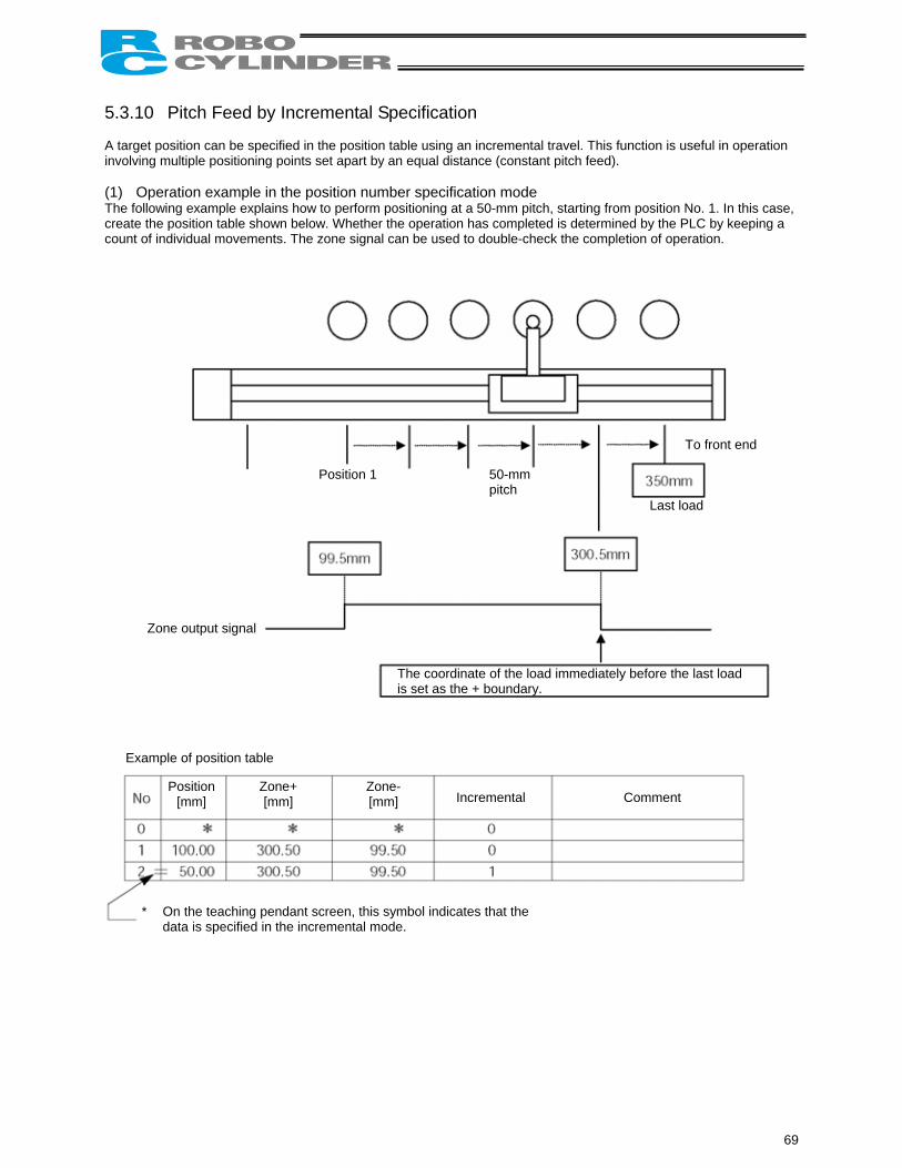
5.3.10 Pitch Feed by Incremental Specification A target position can be specified in the position table using an incremental travel. This function is useful in operation involving multiple positioning points set apart by an equal distance (constant pitch feed). (1) Operation example in the position number specification mode The following example explains how to perform positioning at a 50-mm pitch, starting from position No. 1. In this case, create the position table shown below. Whether the operation has completed is determined by the PLC by keeping a count of individual movements. The zone signal can be used to double-check the completion of operation.
Position 1 50-mm pitch
To front end
Last load
Exa
*
Zone output signal
Ti
mple of position table
Position [mm]
Zone+ [mm]
Zone-[mm]
he coordinate of the load immediately before the last load
s set as the + boundary.Incremental Comment
On the teaching pendant screen, this symbol indicates that the data is specified in the incremental mode.
69
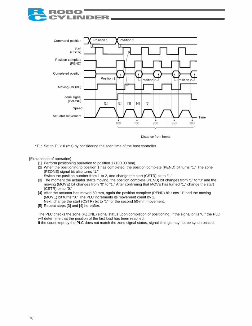
C
C
A
Position 1 Position 2
Position 1 Position 2 Position 2
[1] [2] [3] [4] [5]
*T1: Set to [Explanation of
[1] Perform[2] When
(PZONSwitch
[3] The momoving(CSTR
[4] After th(MOVENext, c
[5] Repea The PLC cwill determIf the coun
70
ommand position
Start(CSTR)
Position complete(PEND)
ompleted position
Moving (MOVE)
Zone signal(PZONE)
ctuator movement
Speed
Time
Distance from home
T1 ≥ 0 (ms) by considering the scan time of the host controller.
operation] positioning operation to position 1 (100.00 mm).
the positioning to position 1 has completed, the position complete (PEND) bit turns “1.” The zone E) signal bit also turns “1.” the position number from 1 to 2, and change the start (CSTR) bit to “1.” ment the actuator starts moving, the position complete (PEND) bit changes from “1” to “0” and the (MOVE) bit changes from “0” to “1.” After confirming that MOVE has turned “1,” change the start ) bit to “0.” e actuator has moved 50 mm, again the position complete (PEND) bit turns “1” and the moving ) bit turns “0.” The PLC increments its movement count by 1. hange the start (CSTR) bit to “1” for the second 50-mm movement. t steps [3] and [4] hereafter.
hecks the zone (PZONE) signal status upon completion of positioning. If the signal bit is “0,” the PLC ine that the position of the last load has been reached. t kept by the PLC does not match the zone signal status, signal timings may not be synchronized.
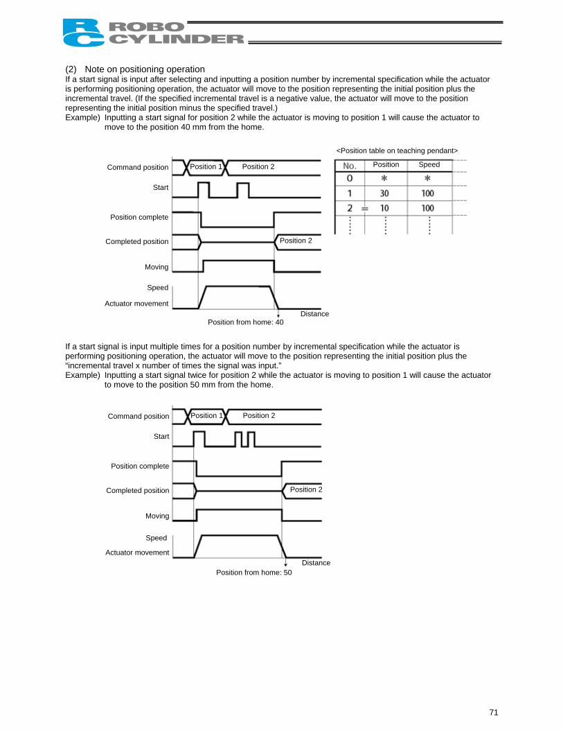
(2) Note on positioning operation If a start signal is input after selecting and inputting a position number by incremental specification while the actuator is performing positioning operation, the actuator will move to the position representing the initial position plus the incremental travel. (If the specified incremental travel is a negative value, the actuator will move to the position representing the initial position minus the specified travel.) Example) Inputting a start signal for position 2 while the actuator is moving to position 1 will cause the actuator to
move to the position 40 mm from the home. If a start signperforming p“incrementaExample) In
to
C
C
A
Position 1 Position 2
Position 2
Position Speed
<Position table on teaching pendant>
C
C
A
ommand position
Start
Position complete
ompleted position
Moving
ctuator movement
Speed
al is input multiple times for a position number by incremental specification while the actuator is ositioning operation, the actuator will move to the position representing the initial position plus the
l travel x number of times the signal was input.” putting a start signal twice for position 2 while the actuator is moving to position 1 will cause the actuator move to the position 50 mm from the home.
Position from home: 40Distance
Position 1 Position 2
Position 2
ommand position
Start
Position complete
ompleted position
Moving
ctuator movement
Speed
Position from home: 50Distance
71
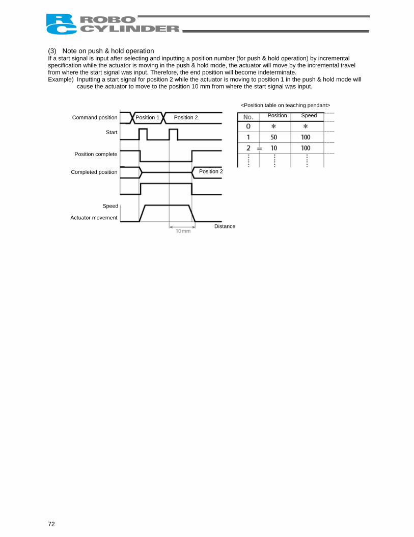
(3) Note on push & hold operation If a start signal is input after selecting and inputting a position number (for push & hold operation) by incremental specification while the actuator is moving in the push & hold mode, the actuator will move by the incremental travel from where the start signal was input. Therefore, the end position will become indeterminate. Example) Inputting a start signal for position 2 while the actuator is moving to position 1 in the push & hold mode will
cause the actuator to move to the position 10 mm from where the start signal was input.
C
C
A
Position 1 Position 2
Position 2
Position Speed
<Position table on teaching pendant>
72
ommand position
Position complete
ompleted position
ctuator movement
Start
Speed
Distance
5.3.11 Power-Saving Mode at Standby Positions One general feature of pulse motors is that their holding current is greater than AC servo motors in a standstill state. Therefore, we provide a power-saving mode to reduce power consumption in situations where the actuator remains standstill for a long period at a standby position. Use this function after confirming that it will not present problems to any part of your system. Specifically, the full servo control mode can be selected for saving power in the following three conditions:
(1) When the actuator stands by with the servo on after the power has been turned on (before home return is completed)
(2) When the actuator stands by after the home return operation effected by the HOME input signal has completed
(3) When the actuator stands by after reaching the target position
Set “0” or “4” in parameter No. 53. Setting Disable power-saving mode (complete stop) 0 Full servo control mode 4
Full servo control mode The pulse motor is servo-controlled to reduce the holding current. Although the exact degree of current reduction varies depending on the actuator model, load condition, etc., the holding current decreases to approx. one-half to one-fourth. Since the servo remains on, no position deviation occurs. The actual holding current can be checked in the current monitor screen of the PC software. Take note that micro-vibration or noise may occur in certain conditions where external force is applied, or depending on the position where the actuator has stopped. If micro-vibration or noise presents problem, do not use this mode.
Caution: In push & hold operation, the full servo control mode becomes ineffective once the operation has completed successfully. If the actuator has missed the load, the full servo control mode becomes effective.
73
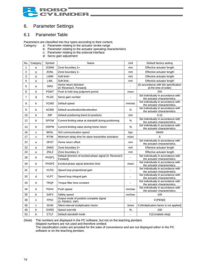
6. Parameter Settings 6.1 Parameter Table Parameters are classified into four types according to their content. Category: a: Parameter relating to the actuator stroke range
b: Parameter relating to the actuator operating characteristics c: Parameter relating to the external interface d: Servo gain adjustment
No. Category Symbol Name Unit Default factory setting 1 a ZONM Zone boundary 1+ mm Effective actuator length 2 a ZONL Zone boundary 1– mm Effective actuator length 3 a LIMM Soft limit+ mm Effective actuator length 4 a LIML Soft limit– mm Effective actuator length
5 a ORG Home return direction (0: Reverse/1: Forward) - (In accordance with the specification
at the time of order) 6 b PSWT Push & hold stop judgment period msec 255
7 d PLG0 Servo gain number - Set individually in accordance with the actuator characteristics.
8 b VCMD Default speed mm/sec Set individually in accordance with the actuator characteristics.
9 b ACMD Default acceleration/deceleration G Set individually in accordance with the actuator characteristics.
10 b INP Default positioning band (in-position) mm 0.10
12 b SPOW Current-limiting value at standstill during positioning % Set individually in accordance with the actuator characteristics.
13 b ODPW Current-limiting value during home return % Set individually in accordance with the actuator characteristics.
16 c BRSL SIO communication speed bps 38400 17 c RTIM Minimum delay time for slave transmitter activation msec 5
22 a OFST Home return offset mm Set individually in accordance with the actuator characteristics.
23 a ZNM2 Zone boundary 2+ mm Effective actuator length 24 a ZNL2 Zone boundary 2– mm Effective actuator length
28 b PHSP1 Default direction of excited-phase signal (0: Reverse/1: Forward) - Set individually in accordance with
the actuator characteristics.
29 b PHSP2 Excited-phase signal detection time msec Set individually in accordance with the actuator characteristics.
31 d VLPG Speed loop proportional gain - Set individually in accordance with the actuator characteristics.
32 d VLPT Speed loop integral gain - Set individually in accordance with the actuator characteristics.
33 d TRQF Torque filter time constant - Set individually in accordance with the actuator characteristics.
34 b PSHV Push speed mm/sec Set individually in accordance with the actuator characteristics.
35 b SAFV Safety speed mm/sec 100
39 c FPIO Output mode of position complete signal (0: PEND/1: INP) - 0 [PEND]
45 c SIVM Silent interval multiplication factor times 0 (Multiplication factor is not applied)46 b OVRD Speed override % 100 53 b CTLF Default standstill mode - 0 [Complete stop]
(Note) The numbers are displayed in the PC software, but not on the teaching pendant. Skipped numbers are not used and therefore omitted. The classification codes are provided for the sake of convenience and are not displayed either in the PC software or on the teaching pendant.
74
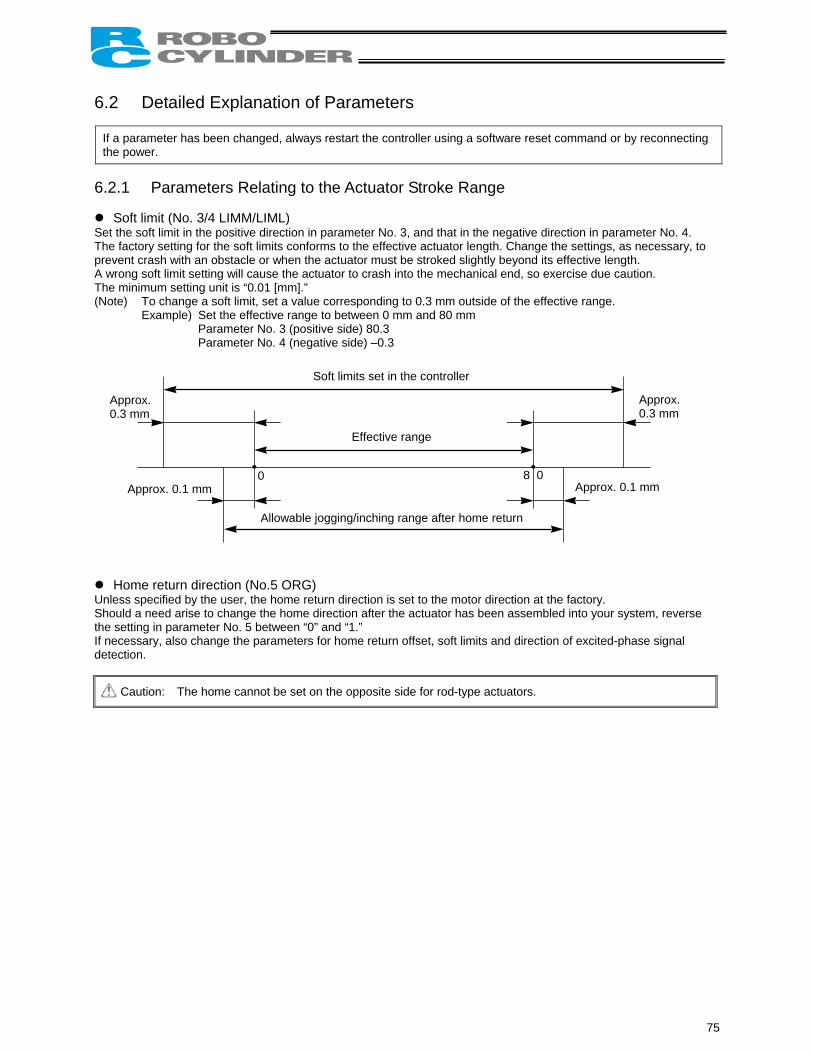
6.2 Detailed Explanation of Parameters
If a parameter has been changed, always restart the controller using a software reset command or by reconnecting the power.
6.2.1 Parameters Relating to the Actuator Stroke Range
Soft limit (No. 3/4 LIMM/LIML) Set the soft limit in the positive direction in parameter No. 3, and that in the negative direction in parameter No. 4. The factory setting for the soft limits conforms to the effective actuator length. Change the settings, as necessary, to prevent crash with an obstacle or when the actuator must be stroked slightly beyond its effective length. A wrong soft limit setting will cause the actuator to crash into the mechanical end, so exercise due caution. The minimum setting unit is “0.01 [mm].” (Note) To change a soft limit, set a value corresponding to 0.3 mm outside of the effective range.
Example) Set the effective range to between 0 mm and 80 mm Parameter No. 3 (positive side) 80.3 Parameter No. 4 (negative side) –0.3
Soft limits set in the controller
Approx. 0.3 mm
Effective range
Allowable jogging/inching range after home return
Approx. 0.1 mm Approx. 0.1 mm
Approx. 0.3 mm
8 0 0
Home return direction (No.5 ORG) Unless specified by the user, the home return direction is set to the motor direction at the factory. Should a need arise to change the home direction after the actuator has been assembled into your system, reverse the setting in parameter No. 5 between “0” and “1.” If necessary, also change the parameters for home return offset, soft limits and direction of excited-phase signal detection.
Caution: The home cannot be set on the opposite side for rod-type actuators.
75
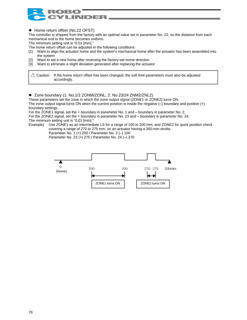
Home return offset (No.22 OFST) The controller is shipped from the factory with an optimal value set in parameter No. 22, so the distance from each mechanical end to the home becomes uniform. The minimum setting unit is “0.01 [mm].” The home return offset can be adjusted in the following conditions: [1] Want to align the actuator home and the system’s mechanical home after the actuator has been assembled into
the system [2] Want to set a new home after reversing the factory-set home direction [3] Want to eliminate a slight deviation generated after replacing the actuator
Caution: If the home return offset has been changed, the soft limit parameters must also be adjusted accordingly.
Zone boundary (1: No.1/2 ZONM/ZONL, 2: No.23/24 ZNM2/ZNL2) These parameters set the zone in which the zone output signal (ZONE1 or ZONE2) turns ON. The zone output signal turns ON when the current position is inside the negative (–) boundary and positive (+) boundary settings. For the ZONE1 signal, set the + boundary in parameter No. 1 and – boundary in parameter No. 2. For the ZONE2 signal, set the + boundary in parameter No. 23 and – boundary in parameter No. 24. The minimum setting unit is “0.01 [mm].” Example) Use ZONE1 as an intermediate LS for a range of 100 to 200 mm, and ZONE2 for quick position check
covering a range of 270 to 275 mm, on an actuator having a 300-mm stroke. Parameter No. 1 (+) 200 / Parameter No. 2 (–) 100 Parameter No. 23 (+) 275 / Parameter No. 24 (–) 270
(Home)
ZONE1 turns ON ZONE2 turns ON
76
6.2.2 Parameters Relating to the Actuator Operating Characteristics
Default speed (No.8 VCMD) The factory setting is the rated speed of the actuator. When a target position is set in an unregistered position table, the setting in this parameter will be used as the speed data for the applicable position number. To reduce the default speed from the rated speed, change the setting in parameter No. 8.
Default acceleration/deceleration (No.9 ACMD) The factory setting is the rated acceleration/deceleration of the actuator. When a target position is set in an unregistered position table, the setting in this parameter will be used as the acceleration/deceleration data for the applicable position number. To reduce the default acceleration/deceleration from the rated acceleration/deceleration, change the setting in parameter No. 9.
Default positioning band (in-position) (No.10 INP) The factory setting is “0.10 [mm].” When a target position is set in an unregistered position table, the setting in this parameter will be used as the positioning band data for the applicable position number. Increasing the default positioning band will allow the position complete signal to be output early. Change the setting in parameter No. 10, as necessary.
Current-limiting value during home return (No.13 ODPW) The factory setting conforms to the standard specification of the actuator. Increasing this setting will increase the home return torque. This setting need not be changed in normal conditions of use. However, if an increased slide resistance causes the home return to complete before the correct position depending on the affixing method, load condition or other factor when the actuator is used in a vertical application, the value set in parameter No. 13 must be increased. (Do not increase the value beyond 75%.)
Current-limiting value at standstill during positioning (No.12 SPOW) The factory setting conforms to the standard specification of the actuator. Increasing this setting will increase the holding torque at standstill. This setting need not be changed in normal conditions of use. However, to prevent hunting caused by large external force applied while the actuator is at standstill, the value set in parameter No. 12 must be increased. (Do not increase the value beyond 70%.)
Speed override (No.46 OVRD) Use this parameter when the actuator needs to be moved at a slower speed to prevent danger when the system is initially started for test operation. When movement commands are issued from the PLC, the specified moving speed can be overridden by the value set in parameter No. 46. Actual moving speed = [Specified speed] x [Value of parameter No. 46] ÷ 100 Example) Specified “speed” 500 (mm/s)
Value of parameter No. 46 20 (%) Under the above settings, the actual moving speed becomes 100 mm/s.
The minimum setting unit is “1 [%],” while the input range is “1 to 100 [%].” The factory setting is “100 [%].” (Note) This parameter is ignored for movement commands issued from a PC or teaching pendant, or movement commands
specified directly as numerical values. If a PC or teaching pendant is connected, a desired speed ratio can be set and applied to actuator operation from the PC or teaching pendant.
77
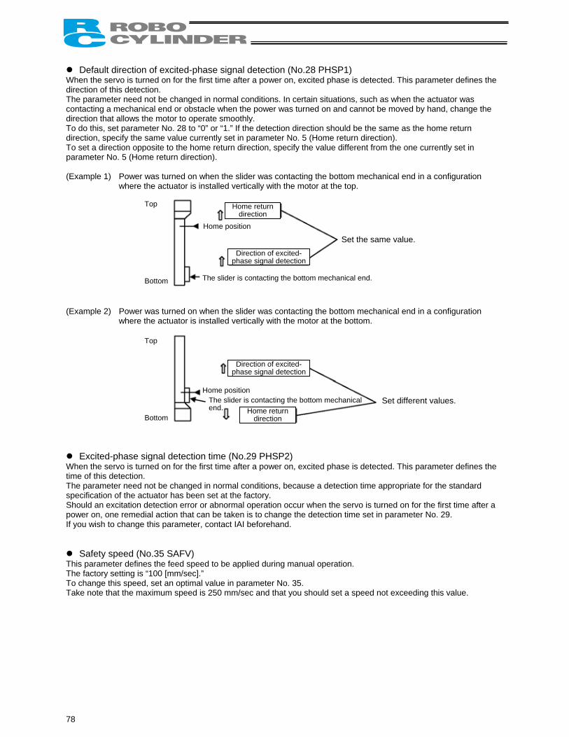
Default direction of excited-phase signal detection (No.28 PHSP1) When the servo is turned on for the first time after a power on, excited phase is detected. This parameter defines the direction of this detection. The parameter need not be changed in normal conditions. In certain situations, such as when the actuator was contacting a mechanical end or obstacle when the power was turned on and cannot be moved by hand, change the direction that allows the motor to operate smoothly. To do this, set parameter No. 28 to “0” or “1.” If the detection direction should be the same as the home return direction, specify the same value currently set in parameter No. 5 (Home return direction). To set a direction opposite to the home return direction, specify the value different from the one currently set in parameter No. 5 (Home return direction). (Example 1) Power was turned on when the slider was contacting the bottom mechanical end in a configuration
where the actuator is installed vertically with the motor at the top.
Top Bottom
Home position
Home return direction
Direction of excited-phase signal detection
The slider is contacting the bottom mechanical end.
Set the same value.
(Example 2) Power was turned on when the slider was contacting the bottom mechanical end in a configuration
where the actuator is installed vertically with the motor at the bottom.
Top Bottom
Home position
Home return direction
The slider is contacting the bottom mechanical end.
Direction of excited-phase signal detection
Set different values.
Excited-phase signal detection time (No.29 PHSP2) When the servo is turned on for the first time after a power on, excited phase is detected. This parameter defines the time of this detection. The parameter need not be changed in normal conditions, because a detection time appropriate for the standard specification of the actuator has been set at the factory. Should an excitation detection error or abnormal operation occur when the servo is turned on for the first time after a power on, one remedial action that can be taken is to change the detection time set in parameter No. 29. If you wish to change this parameter, contact IAI beforehand.
Safety speed (No.35 SAFV) This parameter defines the feed speed to be applied during manual operation. The factory setting is “100 [mm/sec].” To change this speed, set an optimal value in parameter No. 35. Take note that the maximum speed is 250 mm/sec and that you should set a speed not exceeding this value.
78

Default standstill mode (No.53 CTLF) This parameter defines the power-saving mode to be applied when the actuator stands by for a long time while the machine is operating; the actuator stands by for a long time after completing home return operation; or the actuator stands by for a long time after completing positioning operation in the numerical specification mode. Define whether to enable or disable power-saving in parameter No. 53.
Setting All power-saving modes are disabled. 0 Full servo control mode 4 The factory setting is “0 [Disable].” Full servo control mode
The pulse motor is servo-controlled to reduce the holding current. Although the exact degree of current reduction varies depending on the actuator model, load condition, etc., the holding current decreases to approx. one-half to one-fourth. Since the servo remains on, no position deviation occurs. The actual holding current can be checked in the current monitor screen of the PC software.
79
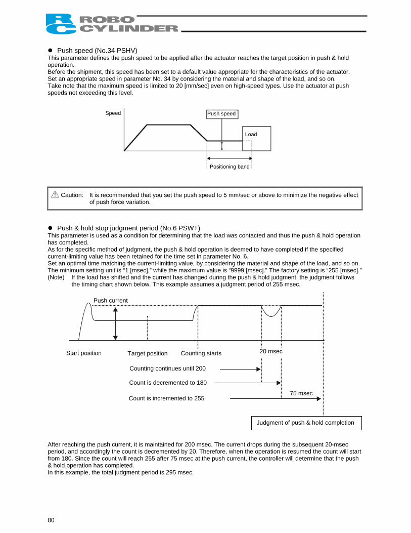
Push speed (No.34 PSHV) This parameter defines the push speed to be applied after the actuator reaches the target position in push & hold operation. Before the shipment, this speed has been set to a default value appropriate for the characteristics of the actuator. Set an appropriate speed in parameter No. 34 by considering the material and shape of the load, and so on. Take note that the maximum speed is limited to 20 [mm/sec] even on high-speed types. Use the actuator at push speeds not exceeding this level.
Speed
Load
Positioning band
Push speed
Caution: It is recommended that you set the push speed to 5 mm/sec or above to minimize the negative effect of push force variation.
Push & hold stop judgment period (No.6 PSWT) This parameter is used as a condition for determining that the load was contacted and thus the push & hold operation has completed. As for the specific method of judgment, the push & hold operation is deemed to have completed if the specified current-limiting value has been retained for the time set in parameter No. 6. Set an optimal time matching the current-limiting value, by considering the material and shape of the load, and so on. The minimum setting unit is “1 [msec],” while the maximum value is “9999 [msec].” The factory setting is “255 [msec].” (Note) If the load has shifted and the current has changed during the push & hold judgment, the judgment follows
the timing chart shown below. This example assumes a judgment period of 255 msec.
Push current
20 msec Start position Target position Counting starts
Counting continues until 200
Count is decremented to 180
Count is incremented to 255
Judgment of push & hold completion
75 msec
After reaching the push current, it is maintained for 200 msec. The current drops during the subsequent 20-msec period, and accordingly the count is decremented by 20. Therefore, when the operation is resumed the count will start from 180. Since the count will reach 255 after 75 msec at the push current, the controller will determine that the push & hold operation has completed. In this example, the total judgment period is 295 msec.
80
6.2.3 Parameters Relating to the External Interface
Output mode of position complete signal (No.39 FPIO) This parameter defines the status of position complete signal to be applied if the servo turns off or “position deviation” occurs while the actuator is standing still after completing positioning. The following two conditions can be considered: [1] The position has deviated, due to external force and while the servo was on, beyond the specified “positioning
band.” [2] The position has deviated, due to external force and while the servo was off, beyond the specified “positioning
band.” To support the above two conditions, how the “position complete status” is monitored can be specified flexibly in accordance with the characteristics of the system or sequence circuit on the PLC side. Among others, it is recommended that this parameter be set to “1 [INP]” if position complete signals are to be used like auto-switches on an air cylinder. The ON/OFF status of each position complete signal is controlled as follows in accordance with the setting of parameter No. 39.
Setting of parameter No. 39
Description
0 [PEND] [1] When the servo is on The position complete signal remains ON even after the current position has exited the range set by the specified “positioning band” with respect to the target position. [2] When the servo is off The position complete signal is OFF unconditionally regardless of the current position.
1 [INP] Regardless of the servo on/off status, the position complete signal turns ON if the current position is within the range set by the specified “positioning band” with respect to the target position, and turns OFF if the current position is outside this range. * In this mode, position complete signals are used just like auto-switches on an air cylinder.
The factory setting is “0 [PEND].”
SIO communication speed (No.16 BRSL) If specified, this parameter sets the communication speed to be applied when the actuator is controlled via serial communication by means of the PLC’s communication module. Set an appropriate value in parameter No. 16 in accordance with the specification of the communication module. You can select “9600,” “19200,” “38400,” “115200” or “230400” bps. The factory setting is “38400 [bps].”
Minimum delay for slave transmitter activation (No.17 RTIM) If specified, this parameter sets the minimum delay time after the controller has received a command until the transmitter is activated, when serial communication is performed by means of the PLC’s communication module. The factory setting is “5 [msec].” However, if the specification of the communication module is 5 msec or above, set the necessary time in parameter No. 17.
81

Silent interval multiplication factor (No.45 SIVM) It is applied to controllers of RS485 serial communication type. If specified, this parameter defines the multiplication factor to be applied to the silent interval time for delimiter judgment in the RTU mode. The default setting is the communication time corresponding to 3.5 characters in accordance with the Modbus specification. This setting need not be changed for normal operations performed with a PC or teaching pendant. If the scan time of the PLC is not optimal and the character transmission interval exceeds the silent interval, the silent interval time can be extended using parameter No. 45. The minimum setting unit is “1 [time],” while the input range is “0 to 10.” If “0” is set, no multiplication factor is applied.
82
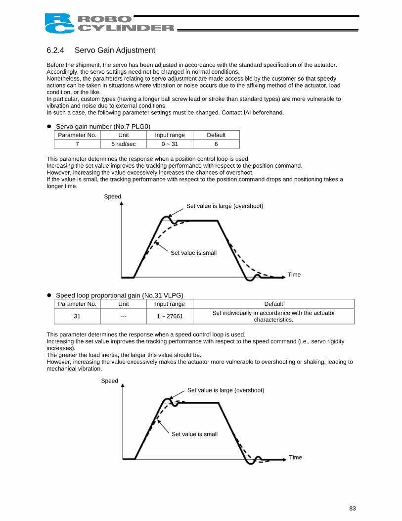
6.2.4 Servo Gain Adjustment Before the shipment, the servo has been adjusted in accordance with the standard specification of the actuator. Accordingly, the servo settings need not be changed in normal conditions. Nonetheless, the parameters relating to servo adjustment are made accessible by the customer so that speedy actions can be taken in situations where vibration or noise occurs due to the affixing method of the actuator, load condition, or the like. In particular, custom types (having a longer ball screw lead or stroke than standard types) are more vulnerable to vibration and noise due to external conditions. In such a case, the following parameter settings must be changed. Contact IAI beforehand.
Servo gain number (No.7 PLG0) Parameter No. Unit Input range Default
7 5 rad/sec 0 ~ 31 6 This parameter determines the response when a position control loop is used. Increasing the set value improves the tracking performance with respect to the position command. However, increasing the value excessively increases the chances of overshoot. If the value is small, the tracking performance with respect to the position command drops and positioning takes a longer time. Speed
Set value is large (overshoot)
Set value is small
Time
Speed loop proportional gain (No.31 VLPG) Parameter No. Unit Input range Default
31 --- 1 ~ 27661 Set individually in accordance with the actuator characteristics.
This parameter determines the response when a speed control loop is used. Increasing the set value improves the tracking performance with respect to the speed command (i.e., servo rigidity increases). The greater the load inertia, the larger this value should be. However, increasing the value excessively makes the actuator more vulnerable to overshooting or shaking, leading to mechanical vibration.
Speed Set value is large (overshoot)
Set value is small
Time
83
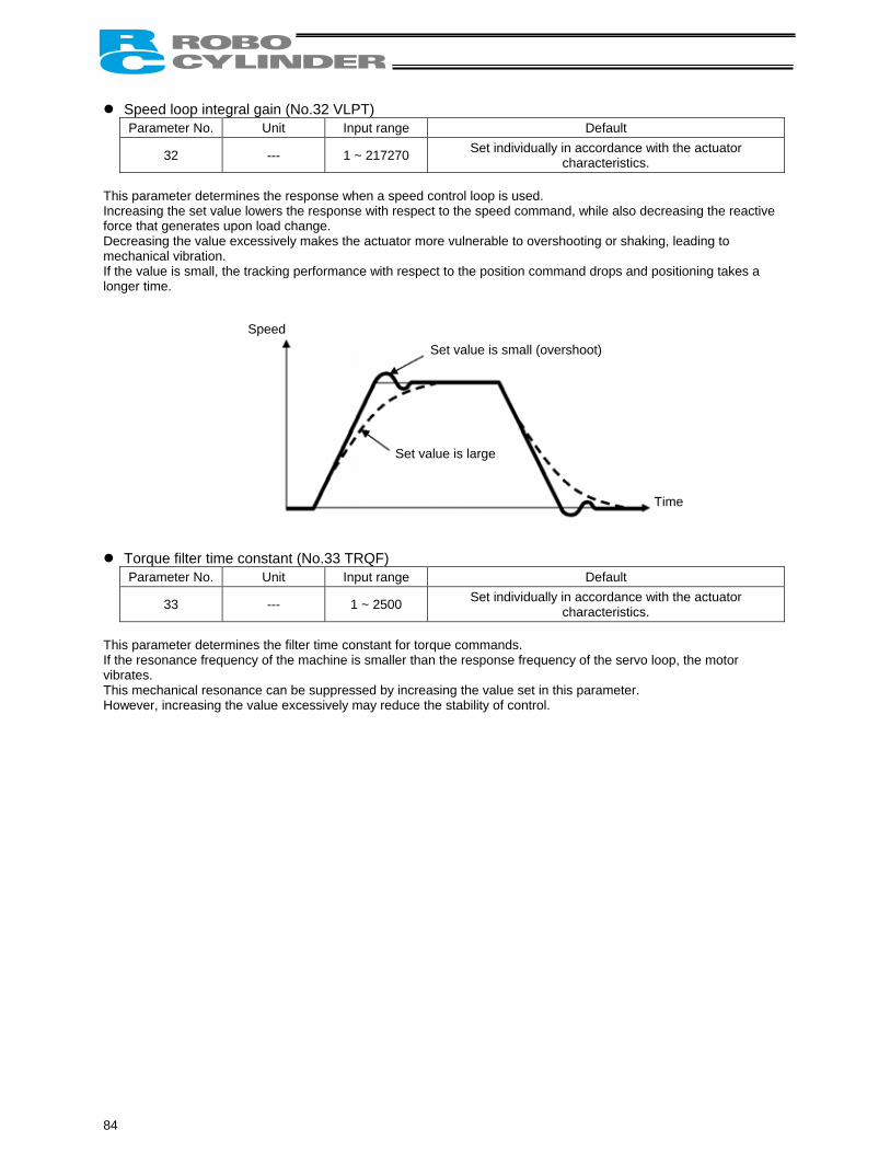
Speed loop integral gain (No.32 VLPT) Parameter No. Unit Input range Default
32 --- 1 ~ 217270 Set individually in accordance with the actuator characteristics.
This parameter determines the response when a speed control loop is used. Increasing the set value lowers the response with respect to the speed command, while also decreasing the reactive force that generates upon load change. Decreasing the value excessively makes the actuator more vulnerable to overshooting or shaking, leading to mechanical vibration. If the value is small, the tracking performance with respect to the position command drops and positioning takes a longer time. Speed
Set value is small (overshoot)
Set value is large
Time
Torque filter time constant (No.33 TRQF) Parameter No. Unit Input range Default
33 --- 1 ~ 2500 Set individually in accordance with the actuator characteristics.
This parameter determines the filter time constant for torque commands. If the resonance frequency of the machine is smaller than the response frequency of the servo loop, the motor vibrates. This mechanical resonance can be suppressed by increasing the value set in this parameter. However, increasing the value excessively may reduce the stability of control.
84
7. Troubleshooting 7.1 Action to Be Taken upon Occurrence of Problem Upon occurrence of a problem, take appropriate action according to the procedure below in order to ensure speedy recovery and prevent recurrence of the problem. a) Check the status indicator lamps.
Illuminating in green --- The servo is ON. Illuminating in red --- An alarm is present or the motor drive power is cut off.
b) Check for error in the host controller. c) Check the voltage of the main 24-VDC power supply. d) Check for alarm.
Confirm the details of error on the PC or teaching pendant. e) Check the cables for connection error, disconnection or pinching.
Before performing a continuity check, turn off the power (to prevent a runaway actuator) and disconnect the cables (to prevent accidental power connection due to a sneak current path).
f) Check the I/O signals. g) Check the noise elimination measures (grounding, installation of surge killer, etc.). h) Review the events leading to the occurrence of problem, as well as the operating condition at the time of
occurrence. i) Check the serial numbers of the actuator. j) Analyze the cause. k) Take action.
Please check items a) through i) before contacting IAI.
85
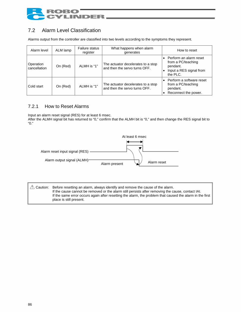
7.2 Alarm Level Classification Alarms output from the controller are classified into two levels according to the symptoms they represent.
Alarm level ALM lamp Failure status register
What happens when alarm generates How to reset
Operation cancellation On (Red) ALMH is “1” The actuator decelerates to a stop
and then the servo turns OFF.
• Perform an alarm reset from a PC/teaching pendant.
• Input a RES signal from the PLC.
Cold start On (Red) ALMH is “1” The actuator decelerates to a stop and then the servo turns OFF.
• Perform a software reset from a PC/teaching pendant.
• Reconnect the power. 7.2.1 How to Reset Alarms Input an alarm reset signal (RES) for at least 6 msec. After the ALMH signal bit has returned to “0,” confirm that the ALMH bit is “0,” and then change the RES signal bit to “0.”
Caution: Before resetting an alarm, always identify and remove the cause of the alarm. If the cause cannot be removed or the alarm still persists after removing the cause, contact IAI. If the same error occurs again after resetting the alarm, the problem that caused the alarm in the first place is still present.
At least 6 msec
Alarm reset input signal (RES)
Alarm output signal (ALMH)Alarm present Alarm reset
86
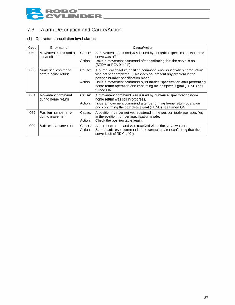
7.3 Alarm Description and Cause/Action (1) Operation-cancellation level alarms Code Error name Cause/Action 080 Movement command at
servo off Cause: A movement command was issued by numerical specification when the
servo was off. Action: Issue a movement command after confirming that the servo is on
(SRDY or PEND is “1”). 083 Numerical command
before home return Cause: A numerical absolute position command was issued when home return
was not yet completed. (This does not present any problem in the position number specification mode.)
Action: Issue a movement command by numerical specification after performing home return operation and confirming the complete signal (HEND) has turned ON.
084 Movement command during home return
Cause: A movement command was issued by numerical specification while home return was still in progress.
Action: Issue a movement command after performing home return operation and confirming the complete signal (HEND) has turned ON.
085 Position number error during movement
Cause: A position number not yet registered in the position table was specified in the position number specification mode.
Action: Check the position table again. 090 Soft reset at servo on Cause: A soft reset command was received when the servo was on.
Action: Send a soft reset command to the controller after confirming that the servo is off (SRDY is “0”).
87
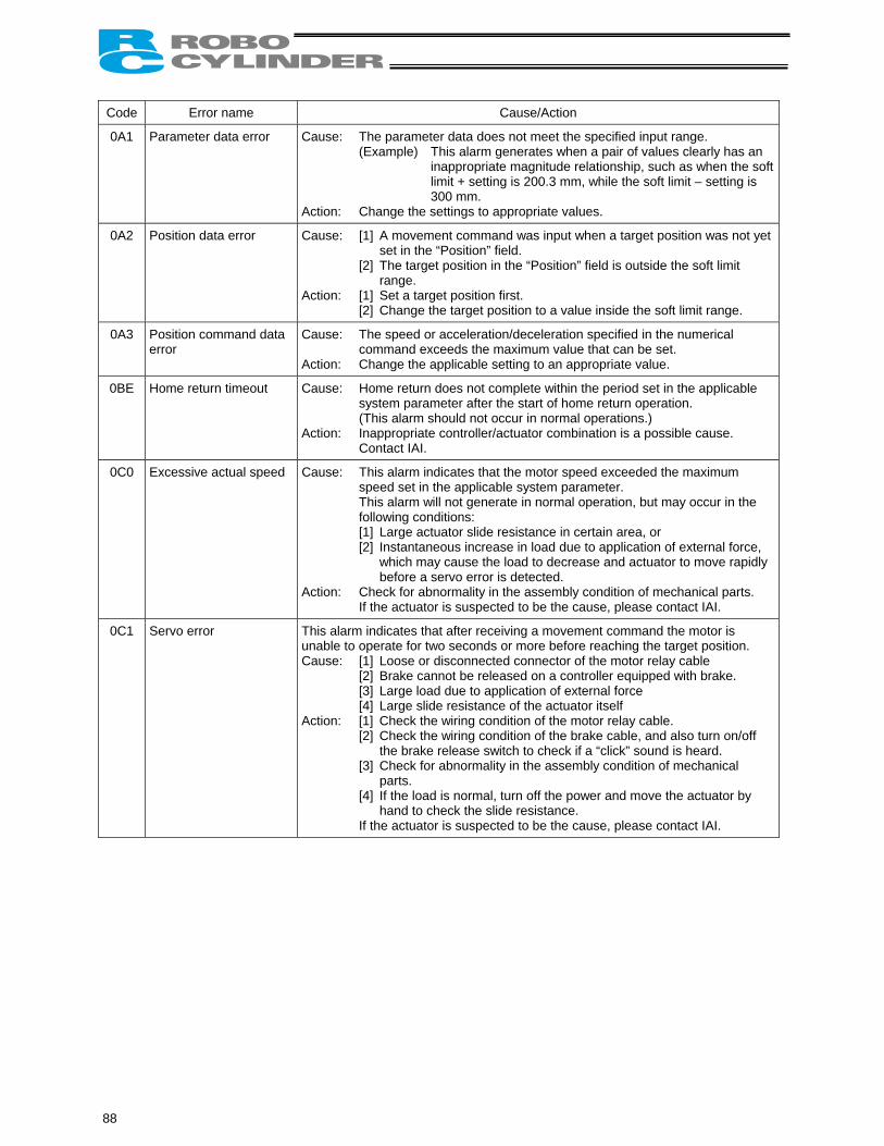
Code Error name Cause/Action
0A1 Parameter data error Cause: The parameter data does not meet the specified input range. (Example) This alarm generates when a pair of values clearly has an
inappropriate magnitude relationship, such as when the soft limit + setting is 200.3 mm, while the soft limit – setting is 300 mm.
Action: Change the settings to appropriate values.
0A2 Position data error Cause: [1] A movement command was input when a target position was not yet set in the “Position” field.
[2] The target position in the “Position” field is outside the soft limit range.
Action: [1] Set a target position first. [2] Change the target position to a value inside the soft limit range.
0A3 Position command data error
Cause: The speed or acceleration/deceleration specified in the numerical command exceeds the maximum value that can be set.
Action: Change the applicable setting to an appropriate value.
0BE Home return timeout Cause: Home return does not complete within the period set in the applicable system parameter after the start of home return operation. (This alarm should not occur in normal operations.)
Action: Inappropriate controller/actuator combination is a possible cause. Contact IAI.
0C0 Excessive actual speed Cause: This alarm indicates that the motor speed exceeded the maximum speed set in the applicable system parameter. This alarm will not generate in normal operation, but may occur in the following conditions: [1] Large actuator slide resistance in certain area, or [2] Instantaneous increase in load due to application of external force,
which may cause the load to decrease and actuator to move rapidly before a servo error is detected.
Action: Check for abnormality in the assembly condition of mechanical parts. If the actuator is suspected to be the cause, please contact IAI.
0C1 Servo error This alarm indicates that after receiving a movement command the motor is unable to operate for two seconds or more before reaching the target position. Cause: [1] Loose or disconnected connector of the motor relay cable
[2] Brake cannot be released on a controller equipped with brake. [3] Large load due to application of external force [4] Large slide resistance of the actuator itself
Action: [1] Check the wiring condition of the motor relay cable. [2] Check the wiring condition of the brake cable, and also turn on/off
the brake release switch to check if a “click” sound is heard. [3] Check for abnormality in the assembly condition of mechanical
parts. [4] If the load is normal, turn off the power and move the actuator by
hand to check the slide resistance. If the actuator is suspected to be the cause, please contact IAI.
88
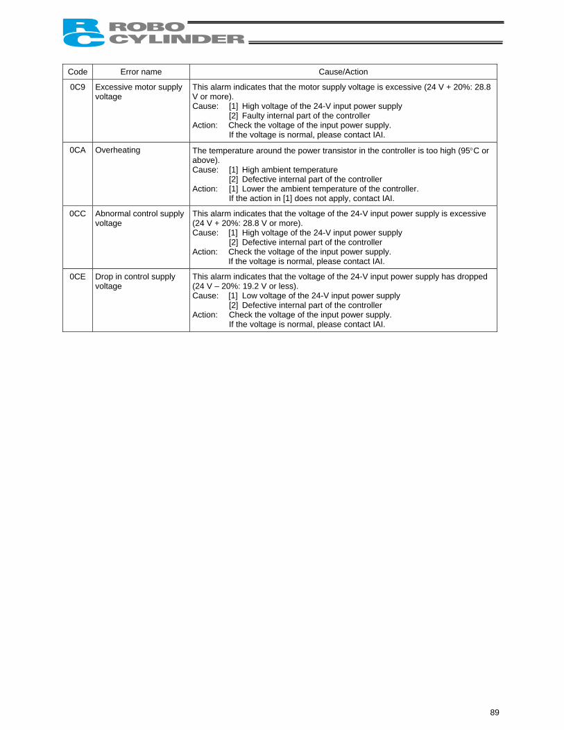
Code Error name Cause/Action
0C9 Excessive motor supply voltage
This alarm indicates that the motor supply voltage is excessive (24 V + 20%: 28.8 V or more). Cause: [1] High voltage of the 24-V input power supply
[2] Faulty internal part of the controller Action: Check the voltage of the input power supply.
If the voltage is normal, please contact IAI.
0CA Overheating The temperature around the power transistor in the controller is too high (95°C or above). Cause: [1] High ambient temperature
[2] Defective internal part of the controller Action: [1] Lower the ambient temperature of the controller. If the action in [1] does not apply, contact IAI.
0CC Abnormal control supply voltage
This alarm indicates that the voltage of the 24-V input power supply is excessive (24 V + 20%: 28.8 V or more). Cause: [1] High voltage of the 24-V input power supply
[2] Defective internal part of the controller Action: Check the voltage of the input power supply. If the voltage is normal, please contact IAI.
0CE Drop in control supply voltage
This alarm indicates that the voltage of the 24-V input power supply has dropped (24 V – 20%: 19.2 V or less). Cause: [1] Low voltage of the 24-V input power supply
[2] Defective internal part of the controller Action: Check the voltage of the input power supply.
If the voltage is normal, please contact IAI.
89
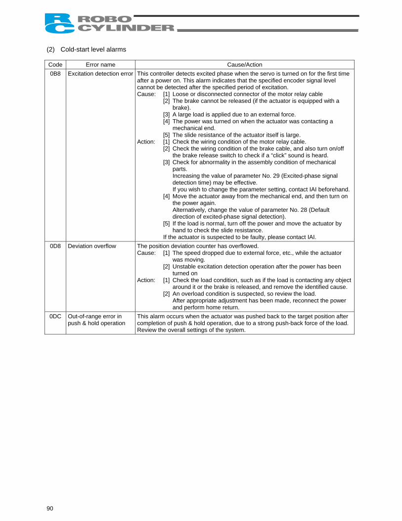
(2) Cold-start level alarms Code Error name Cause/Action 0B8 Excitation detection error This controller detects excited phase when the servo is turned on for the first time
after a power on. This alarm indicates that the specified encoder signal level cannot be detected after the specified period of excitation. Cause: [1] Loose or disconnected connector of the motor relay cable
[2] The brake cannot be released (if the actuator is equipped with a brake).
[3] A large load is applied due to an external force. [4] The power was turned on when the actuator was contacting a
mechanical end. [5] The slide resistance of the actuator itself is large.
Action: [1] Check the wiring condition of the motor relay cable. [2] Check the wiring condition of the brake cable, and also turn on/off
the brake release switch to check if a “click” sound is heard. [3] Check for abnormality in the assembly condition of mechanical
parts. Increasing the value of parameter No. 29 (Excited-phase signal detection time) may be effective. If you wish to change the parameter setting, contact IAI beforehand.
[4] Move the actuator away from the mechanical end, and then turn on the power again. Alternatively, change the value of parameter No. 28 (Default direction of excited-phase signal detection).
[5] If the load is normal, turn off the power and move the actuator by hand to check the slide resistance.
If the actuator is suspected to be faulty, please contact IAI. 0D8 Deviation overflow The position deviation counter has overflowed.
Cause: [1] The speed dropped due to external force, etc., while the actuator was moving.
[2] Unstable excitation detection operation after the power has been turned on
Action: [1] Check the load condition, such as if the load is contacting any object around it or the brake is released, and remove the identified cause.
[2] An overload condition is suspected, so review the load. After appropriate adjustment has been made, reconnect the power and perform home return.
0DC Out-of-range error in push & hold operation
This alarm occurs when the actuator was pushed back to the target position after completion of push & hold operation, due to a strong push-back force of the load. Review the overall settings of the system.
90
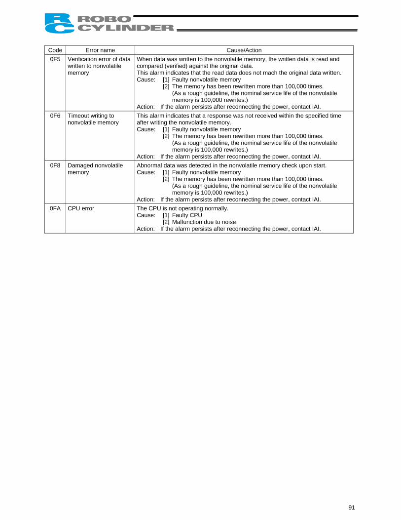
Code Error name Cause/Action 0F5 Verification error of data
written to nonvolatile memory
When data was written to the nonvolatile memory, the written data is read and compared (verified) against the original data. This alarm indicates that the read data does not mach the original data written. Cause: [1] Faulty nonvolatile memory
[2] The memory has been rewritten more than 100,000 times. (As a rough guideline, the nominal service life of the nonvolatile memory is 100,000 rewrites.)
Action: If the alarm persists after reconnecting the power, contact IAI. 0F6 Timeout writing to
nonvolatile memory This alarm indicates that a response was not received within the specified time after writing the nonvolatile memory. Cause: [1] Faulty nonvolatile memory
[2] The memory has been rewritten more than 100,000 times. (As a rough guideline, the nominal service life of the nonvolatile memory is 100,000 rewrites.)
Action: If the alarm persists after reconnecting the power, contact IAI. 0F8 Damaged nonvolatile
memory Abnormal data was detected in the nonvolatile memory check upon start. Cause: [1] Faulty nonvolatile memory
[2] The memory has been rewritten more than 100,000 times. (As a rough guideline, the nominal service life of the nonvolatile memory is 100,000 rewrites.)
Action: If the alarm persists after reconnecting the power, contact IAI. 0FA CPU error The CPU is not operating normally.
Cause: [1] Faulty CPU [2] Malfunction due to noise
Action: If the alarm persists after reconnecting the power, contact IAI.
91
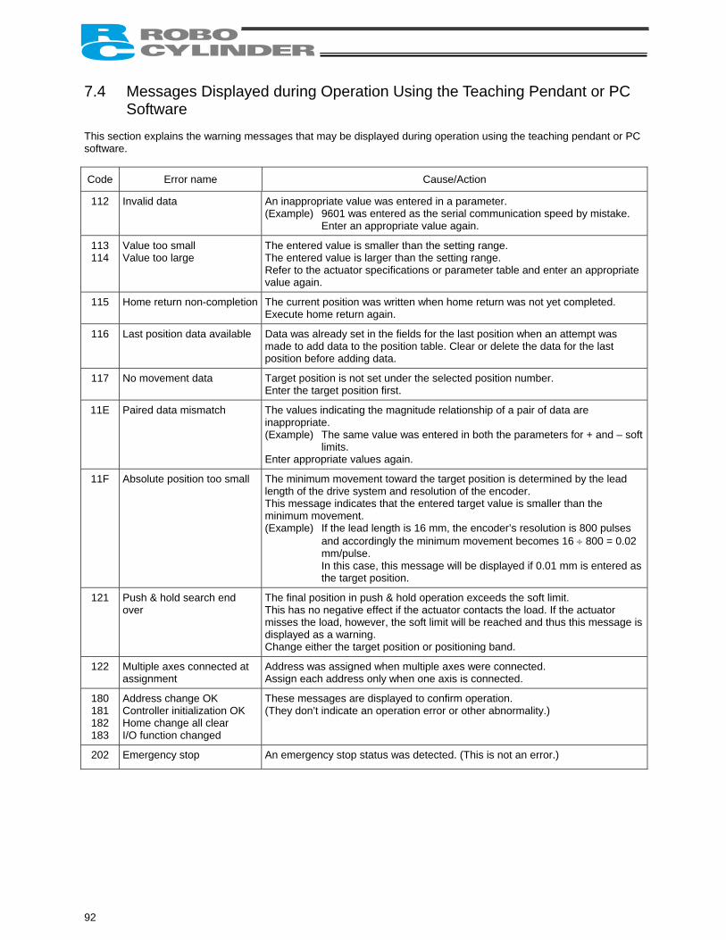
7.4 Messages Displayed during Operation Using the Teaching Pendant or PC
Software This section explains the warning messages that may be displayed during operation using the teaching pendant or PC software.
Code Error name Cause/Action
112 Invalid data An inappropriate value was entered in a parameter. (Example) 9601 was entered as the serial communication speed by mistake. Enter an appropriate value again.
113 114
Value too small Value too large
The entered value is smaller than the setting range. The entered value is larger than the setting range. Refer to the actuator specifications or parameter table and enter an appropriate value again.
115 Home return non-completion The current position was written when home return was not yet completed. Execute home return again.
116 Last position data available Data was already set in the fields for the last position when an attempt was made to add data to the position table. Clear or delete the data for the last position before adding data.
117 No movement data Target position is not set under the selected position number. Enter the target position first.
11E Paired data mismatch The values indicating the magnitude relationship of a pair of data are inappropriate. (Example) The same value was entered in both the parameters for + and – soft
limits. Enter appropriate values again.
11F Absolute position too small The minimum movement toward the target position is determined by the lead length of the drive system and resolution of the encoder. This message indicates that the entered target value is smaller than the minimum movement. (Example) If the lead length is 16 mm, the encoder’s resolution is 800 pulses
and accordingly the minimum movement becomes 16 ÷ 800 = 0.02 mm/pulse. In this case, this message will be displayed if 0.01 mm is entered as the target position.
121 Push & hold search end over
The final position in push & hold operation exceeds the soft limit. This has no negative effect if the actuator contacts the load. If the actuator misses the load, however, the soft limit will be reached and thus this message is displayed as a warning. Change either the target position or positioning band.
122 Multiple axes connected at assignment
Address was assigned when multiple axes were connected. Assign each address only when one axis is connected.
180 181 182 183
Address change OK Controller initialization OK Home change all clear I/O function changed
These messages are displayed to confirm operation. (They don’t indicate an operation error or other abnormality.)
202 Emergency stop An emergency stop status was detected. (This is not an error.)
92
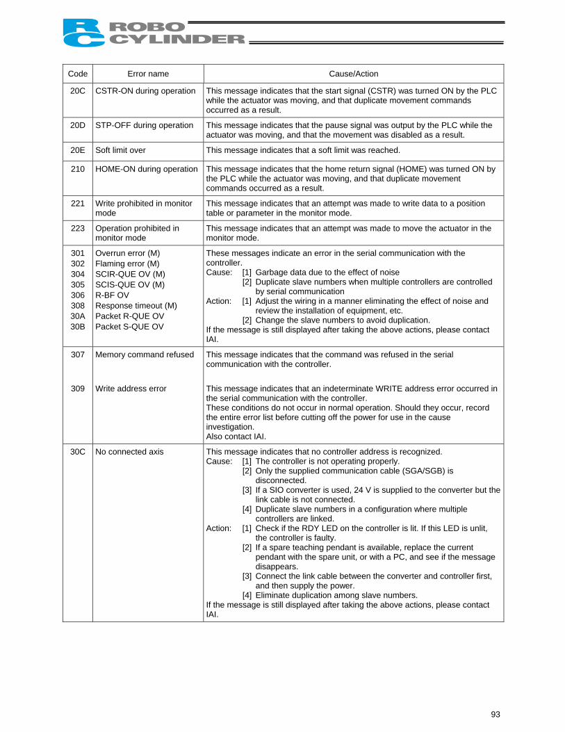
Code Error name Cause/Action
20C CSTR-ON during operation This message indicates that the start signal (CSTR) was turned ON by the PLC while the actuator was moving, and that duplicate movement commands occurred as a result.
20D STP-OFF during operation This message indicates that the pause signal was output by the PLC while the actuator was moving, and that the movement was disabled as a result.
20E Soft limit over This message indicates that a soft limit was reached.
210 HOME-ON during operation This message indicates that the home return signal (HOME) was turned ON by the PLC while the actuator was moving, and that duplicate movement commands occurred as a result.
221 Write prohibited in monitor mode
This message indicates that an attempt was made to write data to a position table or parameter in the monitor mode.
223 Operation prohibited in monitor mode
This message indicates that an attempt was made to move the actuator in the monitor mode.
301 302 304 305 306 308 30A 30B
Overrun error (M) Flaming error (M) SCIR-QUE OV (M) SCIS-QUE OV (M) R-BF OV Response timeout (M) Packet R-QUE OV Packet S-QUE OV
These messages indicate an error in the serial communication with the controller. Cause: [1] Garbage data due to the effect of noise
[2] Duplicate slave numbers when multiple controllers are controlled by serial communication
Action: [1] Adjust the wiring in a manner eliminating the effect of noise and review the installation of equipment, etc.
[2] Change the slave numbers to avoid duplication. If the message is still displayed after taking the above actions, please contact IAI.
307 Memory command refused This message indicates that the command was refused in the serial communication with the controller.
309 Write address error This message indicates that an indeterminate WRITE address error occurred in the serial communication with the controller. These conditions do not occur in normal operation. Should they occur, record the entire error list before cutting off the power for use in the cause investigation. Also contact IAI.
30C No connected axis This message indicates that no controller address is recognized. Cause: [1] The controller is not operating properly.
[2] Only the supplied communication cable (SGA/SGB) is disconnected.
[3] If a SIO converter is used, 24 V is supplied to the converter but the link cable is not connected.
[4] Duplicate slave numbers in a configuration where multiple controllers are linked.
Action: [1] Check if the RDY LED on the controller is lit. If this LED is unlit, the controller is faulty.
[2] If a spare teaching pendant is available, replace the current pendant with the spare unit, or with a PC, and see if the message disappears.
[3] Connect the link cable between the converter and controller first, and then supply the power.
[4] Eliminate duplication among slave numbers. If the message is still displayed after taking the above actions, please contact IAI.
93
7.5 Specific Problems
The LED lamp does not illuminate after the power is input. Cause: [1] Reverse connection of the 24-V power supply
[2] Faulty controller board If the power supply is connected properly, probably the controller board is faulty. Please contact IAI. (Note) If the 24-V power supply is connected in reverse, the controller may not fail immediately but
its service life will likely be shortened.
The LED illuminates in red when the power is turned on. (An alarm is present or the motor drive power is cut off.) Check on the I/O monitor screen of the PC or teaching pendant if the alarm signal (*ALM) is output. If the alarm signal is output, check the description of the error and remove the cause. If alarm code 41 (motor voltage drop) is displayed, it means the motor drive power is cut off. Check the following items: [1] Is the emergency-stop switch on the operation panel pressed? Also confirm that the necessary interlocks are
released. [2] Is the emergency-stop switch on the teaching pendant pressed? [3] If a SIO converter is used, is the PORT switch turned ON when a teaching pendant is not connected?
Home return ends in the middle in a vertical application. Cause: [1] The load exceeds the rating.
[2] The ball screw is receiving torsional stress due to the affixing method of the actuator, tightening of bolts only on one side, etc.
[3] The slide resistance of the actuator itself is large. Action: [1] Increase the value set in user parameter No. 13 (Current-limiting value during home return).
Increasing this value will cause the home return torque to increase, so do not increase the parameter setting above 75%.
[2] Loosen the fixing bolts and check if the slider moves smoothly. If the slider moves smoothly, review the affixing method and bolt tightening condition.
[3] If the slide resistance of the actuator itself is large, please contact IAI.
94
Noise occurs during downward movements in a vertical application. Cause: The load exceeds the rating. Action: [1] Decrease the speed.
[2] Decrease the value set in the user parameter No. 7 (Servo gain number). Do not decrease the parameter setting below “3.”
Vibration occurs when the actuator is stopped. Cause: The slider is receiving an external force. Action: If the external force cannot be removed, increase the value set in user parameter No. 12 (Current-limiting
value at standstill during positioning). Increasing this value will cause the holding torque at standstill to increase, so do not increase the parameter setting above 70%.
The actuator overshoots when decelerated to a stop. Cause: The load inertia is high in view of the balance of load and deceleration. Action: Decrease the deceleration setting.
The home and target positions sometimes shift on the rod-type actuator. Cause: The current-limiting value is lower than what is required in view of the load capacity and slide resistance. Action: The actuator may have to be replaced in some cases. Please contact IAI.
The speed is slow during push & hold operation. Cause: The set current-limiting value is insufficient for the load or slide resistance. Action: Increase the current-limiting value for push & hold operation.
The actuator moves only a half, or as much as twice, the specified travel. Cause: Pre-shipment setting error at IAI is suspected. Action: Contact IAI.
The actuator operates abnormally when the servo is turned on following the power on. Cause: The excited phase is not detected correctly when the servo is turned on because of one of the following
conditions at the time of power on: [1] The slider or rod is contacting the mechanical end. [2] An excessive external force is exerted to the work.
Action: [1] Check if the slider or rod is contacting the mechanical end. If it is, move the slider/rod away from the mechanical end. If the actuator is equipped with a brake, move the slider/rod after releasing the brake by turning on the brake release switch. At this time, pay attention to prevent the work from falling due to its dead weight and protect your hand, robot, and the work from injuries/damages. If the actuator cannot be moved by hand, you can check the direction of excited-phase signal detection and change the direction, if necessary. If you wish to attempt this course of action, please contact IAI. For details, refer to 6.2.2, “Parameters Relating to the Actuator Operating Characteristics.”
[2] Check if the work is in contact with an object in the surroundings. If so, move the work away from the obstruction to provide a minimum clearance of 1 mm. If neither of causes [1] and [2] is present, please contact IAI.
The LED (green) blinks. The automatic servo-off mode is currently active (this mode is not available on this controller). (This is not an error or failure.)
95
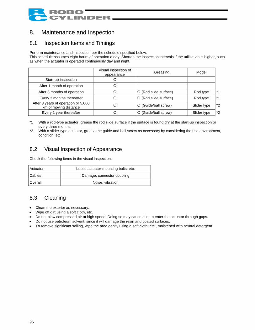
8. Maintenance and Inspection 8.1 Inspection Items and Timings Perform maintenance and inspection per the schedule specified below. This schedule assumes eight hours of operation a day. Shorten the inspection intervals if the utilization is higher, such as when the actuator is operated continuously day and night.
Visual inspection of appearance Greasing Model
Start-up inspection After 1 month of operation After 3 months of operation (Rod slide surface) Rod type *1 Every 3 months thereafter (Rod slide surface) Rod type *1
After 3 years of operation or 5,000 km of moving distance (Guide/ball screw) Slider type *2
Every 1 year thereafter (Guide/ball screw) Slider type *2 *1 With a rod-type actuator, grease the rod slide surface if the surface is found dry at the start-up inspection or
every three months. *2 With a slider-type actuator, grease the guide and ball screw as necessary by considering the use environment,
condition, etc. 8.2 Visual Inspection of Appearance Check the following items in the visual inspection: Actuator Loose actuator-mounting bolts, etc.
Cables Damage, connector coupling
Overall Noise, vibration 8.3 Cleaning • Clean the exterior as necessary. • Wipe off dirt using a soft cloth, etc. • Do not blow compressed air at high speed. Doing so may cause dust to enter the actuator through gaps. • Do not use petroleum solvent, since it will damage the resin and coated surfaces. • To remove significant soiling, wipe the area gently using a soft cloth, etc., moistened with neutral detergent.
96
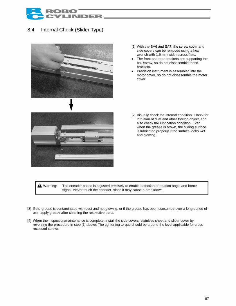
8.4 Internal Check (Slider Type)
[1] With the SA6 and SA7, the screw cover and side covers can be removed using a hex wrench with 1.5 mm width across flats.
• The front and rear brackets are supporting the ball screw, so do not disassemble these brackets.
• Precision instrument is assembled into the motor cover, so do not disassemble the motor cover.
[2] Visually check the internal condition. Check for intrusion of dust and other foreign object, and also check the lubrication condition. Even when the grease is brown, the sliding surface is lubricated properly if the surface looks wet and glowing.
Warning: The encoder phase is adjusted precisely to enable detection of rotation angle and home signal. Never touch the encoder, since it may cause a breakdown.
[3] If the grease is contaminated with dust and not glowing, or if the grease has been consumed over a long period of
use, apply grease after cleaning the respective parts. [4] When the inspection/maintenance is complete, install the side covers, stainless sheet and slider cover by
reversing the procedure in step [1] above. The tightening torque should be around the level applicable for cross-recessed screws.
97
8.5 Internal Cleaning (Slider Type) • Wipe off dirt using a soft cloth, etc. • Do not blow compressed air at high speed. Doing so may cause dust to enter the actuator through gaps. • Do not use petroleum solvent, neutral detergent or alcohol.
Caution: Do not use cleaning oil, molybdenum grease or rustproof lubricant. If a large amount of foreign object is contained in the grease, wipe off the dirty grease before applying new grease.
8.6 Greasing the Guide (Slider Type) (1) Applicable grease IAI uses lithium grease No. 2. The following grease is applied to the guides prior to shipment:
Idemitsu Kosan Daphne Eponex Grease No. 2
Equivalent grease products are available from other companies. For details, contact each manufacturer and ask for a product equivalent to the aforementioned brand. Equivalence of the following products has been confirmed:
Showa Shell Sekiyu Albania Grease No. 2
ExxonMobil Mobilux 2
98
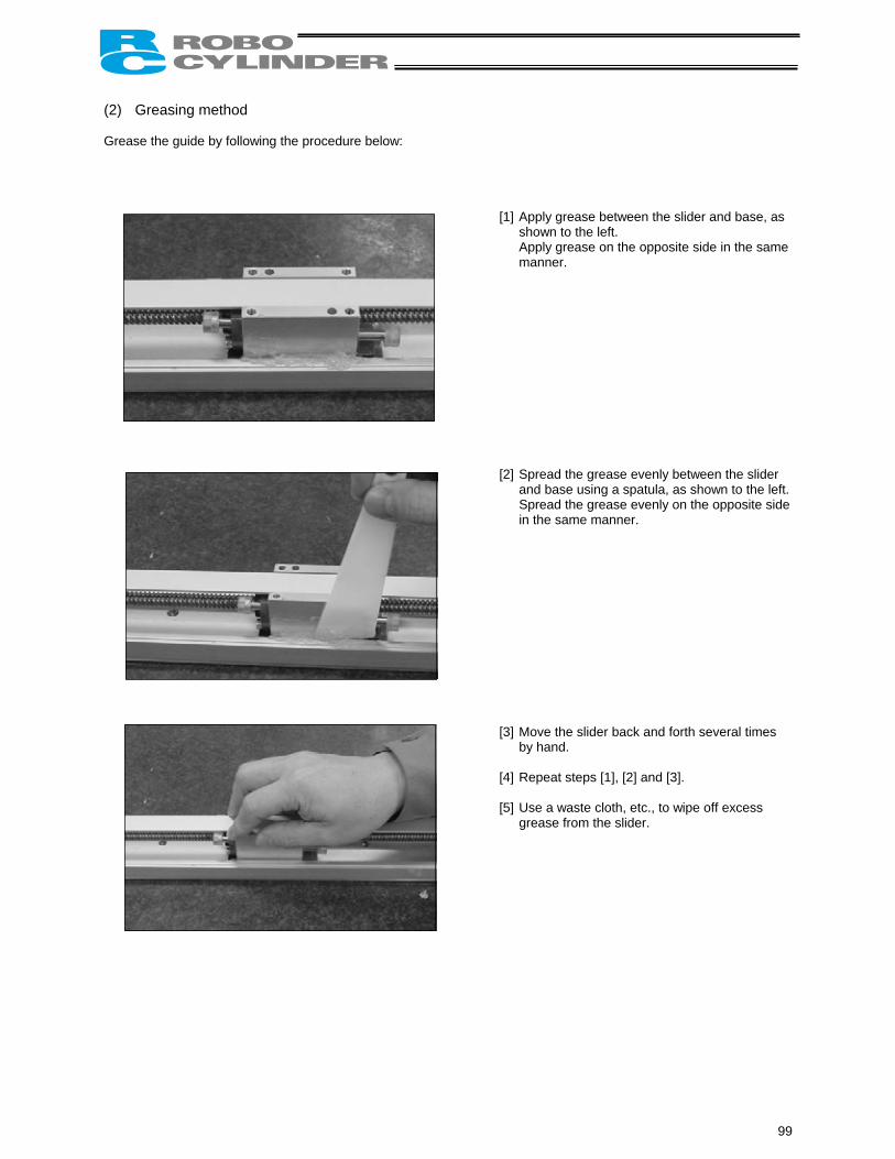
(2) Greasing method Grease the guide by following the procedure below:
[1] Apply grease between the slider and base, as shown to the left. Apply grease on the opposite side in the same manner.
[2] Spread the grease evenly between the slider
and base using a spatula, as shown to the left. Spread the grease evenly on the opposite side in the same manner.
[3] Move the slider back and forth several times
by hand. [4] Repeat steps [1], [2] and [3]. [5] Use a waste cloth, etc., to wipe off excess
grease from the slider.
99
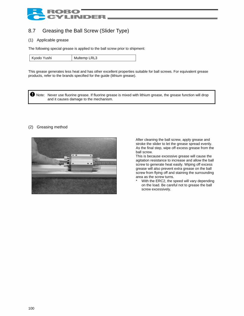
8.7 Greasing the Ball Screw (Slider Type) (1) Applicable grease The following special grease is applied to the ball screw prior to shipment:
Kyodo Yushi Multemp LRL3 This grease generates less heat and has other excellent properties suitable for ball screws. For equivalent grease products, refer to the brands specified for the guide (lithium grease).
Note: Never use fluorine grease. If fluorine grease is mixed with lithium grease, the grease function will drop and it causes damage to the mechanism.
(2) Greasing method
After cleaning the ball screw, apply grease and stroke the slider to let the grease spread evenly. As the final step, wipe off excess grease from the ball screw. This is because excessive grease will cause the agitation resistance to increase and allow the ball screw to generate heat easily. Wiping off excess grease will also prevent extra grease on the ball screw from flying off and staining the surrounding area as the screw turns. * With the ERC2, the speed will vary depending
on the load. Be careful not to grease the ball screw excessively.
100
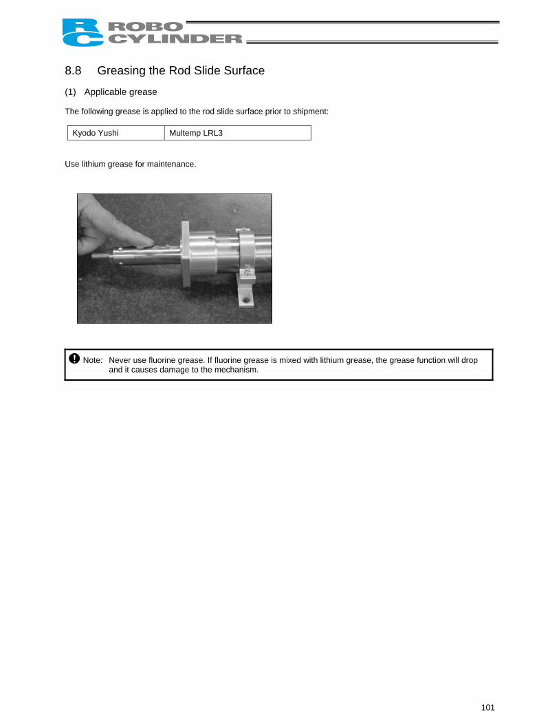
8.8 Greasing the Rod Slide Surface (1) Applicable grease The following grease is applied to the rod slide surface prior to shipment:
Kyodo Yushi Multemp LRL3 Use lithium grease for maintenance.
Note: Never use fluorine grease. If fluorine grease is mixed with lithium grease, the grease function will drop and it causes damage to the mechanism.
101
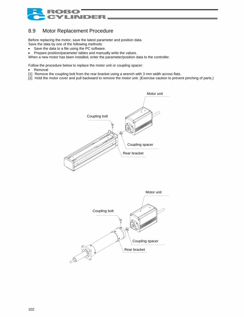
8.9 Motor Replacement Procedure Before replacing the motor, save the latest parameter and position data. Save the data by one of the following methods: • Save the data to a file using the PC software. • Prepare position/parameter tables and manually write the values. When a new motor has been installed, enter the parameter/position data to the controller. Follow the procedure below to replace the motor unit or coupling spacer: • Removal [1] Remove the coupling bolt from the rear bracket using a wrench with 3 mm width across flats. [2] Hold the motor cover and pull backward to remove the motor unit. (Exercise caution to prevent pinching of parts.)
Coupling bolt
Motor unit
Coupling spacer
Rear bracket
Motor unit
Coupling bolt
Coupling spacer
Rear bracket
102
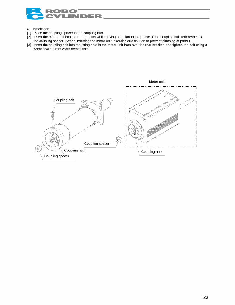
• Installation [1] Place the coupling spacer in the coupling hub. [2] Insert the motor unit into the rear bracket while paying attention to the phase of the coupling hub with respect to
the coupling spacer. (When inserting the motor unit, exercise due caution to prevent pinching of parts.) [3] Insert the coupling bolt into the fitting hole in the motor unit from over the rear bracket, and tighten the bolt using a
wrench with 3 mm width across flats. Motor unit
Coupling bolt
Coupling spacer
Coupling spacer Coupling hub Coupling hub
103

9. Operation Examples Refer to the operation manuals specified below for operation examples using this product:
• Operation Manual for DeviceNet Gateway Unit • Operation Manual for CC-Link Gateway Unit • Operation manual on communication specifications for each serial communication model
104

Sta
ndst
ill m
ode
Com
man
d m
ode
Incr
emen
tal
Rec
orde
d da
te:
Acce
lera
tion/
dece
lera
tion
mod
e
Zone
– [m
m]
Zone
+ [m
m]
Posi
tioni
ng
band
[m
m]
Thre
shol
d [%
]
Push
[%
]
Dec
eler
atio
n [G
]
Acce
lera
tion
[G]
Spee
d [m
m/s
]
Posi
tion
[mm
]
Rec
ordi
ng o
f Pos
ition
Tab
le
No.
1 2 3 4 5 6 7 8 9 10
11
14
12
13
15
105
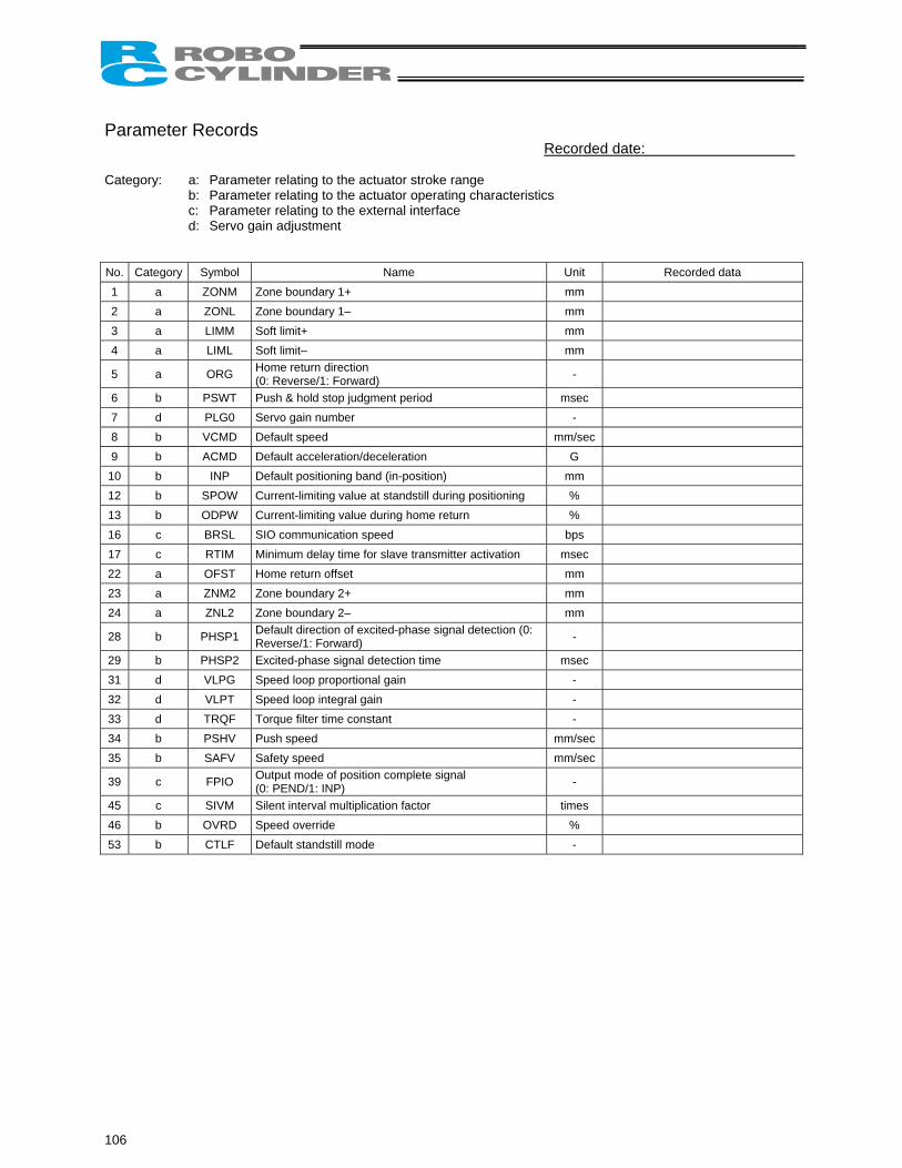
Parameter Records
Recorded date: Category: a: Parameter relating to the actuator stroke range
Category Name
b: Parameter relating to the actuator operating characteristics c: Parameter relating to the external interface d: Servo gain adjustment
No. Symbol Unit Recorded data 1 a ZONM Zone boundary 1+ mm 2 a ZONL Zone boundary 1– mm 3 a Soft limit+ mm LIMM 4 a LIML mm Soft limit–
5 a ORG Home return direction (0: Reverse/1: Forward) -
6 b PSWT Push & hold stop judgment period msec 7 d PLG0 Servo gain number - 8 b VCMD Default speed mm/sec 9 b ACMD Default acceleration/deceleration G
10 b INP Default positioning band (in-position) mm 12 b SPOW Current-limiting value at standstill during positioning % 13 ODPW b Current-limiting value during home return % 16 c BRSL SIO communication speed bps 17 c RTIM Minimum delay time for slave transmitter activation msec 22 a mm OFST Home return offset 23 a ZNM2 Zone boundary 2+ mm 24 ZNL2 Zone boundary 2– mm a
28 b PHSP1 Default direction of excited-phase signal detection (0: Reverse/1: Forward) -
29 b PHSP2 Excited-phase signal detection time msec 31 d VLPG Speed loop proportional gain - 32 d VLPT Speed loop integral gain - 33 d TRQF Torque filter time constant - 34 b PSHV Push speed mm/sec 35 b SAFV Safety speed mm/sec
39 c Output mode of position complete signal - FPIO (0: PEND/1: INP) 45 times c SIVM Silent interval multiplication factor 46 b OVRD Speed override % 53 Default standstill mode - b CTLF
106

107

108

Catalog No.: ERC2-MJ0159-1A-Jan1707-1
Chicago Office: 1261 Hamilton Parkway, Itasca, IL 60143
Website: www.intelligentactuator.com
Ober der Röth 4, D-65824 Schwalbach am Taunus, Germany
Copyright © 2006.Jul. IAI Corporation. All rights reserved.
Head Office: 2690 W. 237th Street, Torrance, CA 90505 TEL (310) 891-6015 FAX (310) 891-0815
TEL (630) 467-9900 FAX (630) 467-9912
TEL 06196-88950 FAX 06196-889524
The information contained in this document is subject to change without notice for the purpose of product improvement.