Embed Size (px)
Citation preview

Office and distributors in principal cities throughout the world. Contact the nearest Ingersoll-Rand office for the name and address of the distributor inyour country or write to: Ingersoll-Rand Company, 1872 Enterprise Drive, Rochester Hills, Michigan, USA 48309
WARNING: Our products are not designed for transporting people orlifting loads over people. It is the user’s responsibility to determine thesuitability of our products for any particular use and to check compliancewith applicable regulations. Before installation, see maintenance andoperations manual for additional warnings and precautions.
Call 1-800-347-7047 for distributors in your area.Visit our web site at:
www.irtools.com
© 2006 Ingersoll Rand Company Form No. MHD55226 Printed in U.S.A./15M
Ergonomic Handling Systems

Engineered for the Interaction of Man and Machine
We at Ingersoll-Rand pioneered the development of pneumatic powered lifting and balancing equipment, making us the world leader in themanufacturing of ergonomic, in-process, manual assist, pick, and place systems.
The combination of Ingersoll-Rand’s 40 years of manufacturing excellence, ISO 9001 certification and 24 hour service network has created a uniqueability to respond to your needs anywhere in the world with the highest quality material handling equipment available.
With a solid commitment to research and development, we have applied our expertise to introduce new products with technology that is state of the artand most sophisticated in the world. Our most recent innovations are the Intelift pneumatic balancers and intelligent handling devices.
For over 40 years, we have been serving the material handling needs of automotive, appliance, aerospace, converting, electronics, food, furniture, glass,packaging, printing, pharmaceutical, sheet metal, textile and warehousing industries worldwide.
In the following pages we present all of our material handling products with several illustrations and descriptions of product features.
Application pictures of Ingersoll-Rand System in the automotive industry.
HOIST MANUFACTURERS INSTITUTE
ISO 9001C E R T I F I E DISO 9001C E R T I F I E D
Call 1-800-347-7047
for distributors in your area
Untitled-1 5/8/06, 11:57 AM2

Rail Systems 1-5
Jib Cranes 6-9
Intelift Pneumatic Balancers 10-16
Balancers 17-24
Arm Systems 25-34
Handling Devices 35-39
Torque Reaction Products 40-48
Irax Spring Balancers 49-55
Quantum Electric Chain Hoists 56-61
I-Beam Specifications 62
Ingersoll-Rand Assembly Solutions
Headquartered in Annandale, New Jersey, offers the broadest range ofergonomic material handling systems in the world. Ingersoll-Rand iscommitted to fulfill our customers’ expectations by providing products,technology and services of the highest quality. Constantly, we strive toachieve world class standards in customer service and foster theinvolvement and dedication of our employees to continuing improvement.Our systems are sold and serviced by a network of distributors around theworld. We appreciate the opportunity to meet your material handlingproduct needs.
For additional Ingersoll-Rand lifting equipmentproducts please refer to our Industrial LiftingEquipment catalog, Form Number MHD55003.
Untitled-1 5/8/06, 11:57 AM3

Rail
Syst
ems
The Backbone of Material Handling Technology
Engineered for the Interaction of Man and Machine.
Backbone to build on
Through a solid commitment to research and development, we have applied our expertise to produce the most complete line of enclosed trackworkstation crane and monorail systems from one manufacturer in the world. Available in aluminum, steel, and stainless steel, these overheadconveyance rails form the backbone for any material handling system.
The Ingersoll-Rand Rail Systems advantage
• Lightweight and Ergonomic: Less than 1% rolling resistance• Precision Running Surface: Aluminum, steel, and stainless steel available• Modular and Flexible: Bolted together; no welding required• Clean, Maintenance-free Operation: No lubrication required• Safety: Designed to meet or exceed all national and international standards
Support steel
Hanger assembly
RunwayBridgecrane
End truckassembly
Safety cable assembly
Rail Systems
1
Untitled-1 5/8/06, 11:57 AM4

Rail
Syst
ems
Quality Steel, Aluminum and Stainless Steel Rail Systems
Ingersoll-Rand rails are available in three different materials and fivedifferent sizes to meet your specific material handling needs. TheEnclosed Rail Systems design reduces the accumulation of dirt andgrime on the internal rolling surfaces, thus reducing rolling effort.
Aluminum
Lightweight and available for long spans
• Extruded: From aluminum alloy 6063-T6• Clear Anodized: For a smooth, clean, corrosive-free surface• ZRAT: Available in lengths up to 24 feet (7 meters)• ZRA1: Available in lengths up to 30 feet (9 meters)• ZRA2: Available in lengths up to 30 feet (9 meters)• Strongbacking: Available for increased capacities
Steel
The strong, economical choice, ideal for heavy weight applications
• Roll Formed: From 9 gauge, A569 hot-rolled steel• Spot Welded: With automated welder for maximum strength• Powder Coat Painted: For durability and smoothness• ZRS2: Available in lengths up to 24 feet (7 meters)• ZRS3: Available in lengths up to 24 feet (7 meters)• Strongbacking: Available for increased capacities
Stainless Steel
Engineered for cleanroom applications, ideal for the food andpharmaceutical industries
• Roll Formed: From 10 gauge, 316L stainless steel• Spot Welded: With automated welder for maximum strength• ZRSS: Available in lengths up to 24 feet (7 meters)
Ingersoll-Rand rail system application shown in amanufacturing facility.
Rail Systems
ZRA1ZRA2ZRSSZRS3 ZRATZRS2
Curved Rail
2
Untitled-1 5/8/06, 11:57 AM5

Rail
Syst
ems
ZRA2Aluminum bridge
ZRS2 Steelrunway
End stop
End stop
Pivoting hanger
Safety cable
Articulating end truck
Safety cable
Adjustable hanger shown with steel rail
Safety First
Ingersoll-Rand’s primary and vital concern issafety.
• Deflection: Ingersoll-Rand rail is designedto not exceed 1/450 of span, in accordancewith ANSI B30.11 Monorail and UnderhungCranes.
• Safety Cables: We require the use of safetycables at all moving (hanger and end-truck)suspension points.
• Redundant End Stops: Available for extrasafety.
• Load Ratings: Clearly marked on both sidesof bridge rails.
• Safety Factor: All hardware componentsare rated at a 5 to 1 safety factor based onmeticulous tests performed at independenttesting laboratories.
Hangers
We offer a wide variety of hangers to attach tovirtually any type of overhead steel. Available ineither rigid (anti-compression) or pivoting stylesto match the material handling operation, thehangers are available in fixed and adjustablelengths for all rails. For extra safety, We requirethat all hangers with a drop of 24 inches orgreater have sway/thrust bracing for stability.
End Trucks
While we offer both articulating and rigid endtrucks to match the material handlingapplication, the primary system sold utilizes thearticulating end truck. This feature maximizesthe ability of the operator to precisely positionloads by allowing them to move only the portionof the bridge crane near the load. This results indramatic improvements over typical rigid endtruck systems which require the user to movethe entire mass of the bridge crane for eachoperation.
Rail Systems
Ingersoll-Rand helps build a Deere
Overhead articulating bridge crane system from Ingersoll-Rand being used in a John Deere™
manufacturing facility.
Courtesy ofModern Material Handling Magazine.
3
Untitled-1 5/8/06, 11:57 AM6

Rail
Syst
ems
Advanced Trolley Design
Ingersoll-Rand trolleys are designed to work in conjunction with theEnclosed Track Rail to reduce the rolling effort required to move aload. In fact, only a force equal to one percent of the total rollingweight is needed when moving loads.
• Lightweight: Trolleys are primarily made from high-strength Almagcastings. Also available in steel and stainless steel stampings.
• Injection Molded Wheels: Provide for clean, wear-free operation thatresists flattening.
• Sealed Precision Bearings: In wheels and side guide rollers, theyprovide long life and reduced maintenance.
• Rail Safety Lug: Prevents the body of the trolley from being pulledthrough the enclosed track rail.
• Versatile: Ingersoll-Rand-built trolleys are available for use in virtuallyevery manufacturer’s enclosed track rail system.
High tensile lightweightaluminum casting
Rail safety lug
Delrin wheels andside guide rollers
Sealed andlubricatedball bearings
Optional third “reaction”anti-kick up wheel forcantilevered loads
Ingersoll-Rand bridge and runway system in a manufacturing plant.
Rail Systems
Free Standing Workstation and Crane Systems
Ingersoll-Rand offers both standard and custom free standing floorsupported systems. These systems allow for the placement of workstationrail systems independent of existing overhead structural steel.
4
Untitled-1 5/8/06, 11:57 AM7

Rail
Syst
ems
Powered track switch for use in monorail applications
Rail Systems
Power Supply
Air supply: Kits are available in both 3/8” and 1/2”. Kits are available with a filter/regulator for use with Balancers and manipulator systems. We alsosupply air supply kits without the filter/regulator for use with oil-based pneumatic systems such as hoists and tractor drives.
Electrical supply: Kits are available to supplement virtually any type of electrical equipment. Insul-8 electrification systems are available.
Accessories
A wide range of accessories such as curved rail, track switches, bridgeextensions, and custom designed components are available to enhanceany crane or monorail system.
Air supply festooning using pre coil tube assembly Electric supply using Insul-8
Eye Bolt Assy.
Supply
AIR FLOW
ThimblesWire Rope Clamps Tag Line Wire Shut Off Valve
Air Regulator and Guage Assy.
Air Filter
Pre-Coil Hose
Straight Hose Assy.
Pipe Fittings
Air Bracket Assy.Air Supply Assembly
Keeps coil hose and electricalsupply in place. Allowscomplete utilization of thebridge and runway system.Filter Regulator providesclean regulated air.
5
Untitled-1 5/8/06, 11:58 AM8
Jib
Cran
es
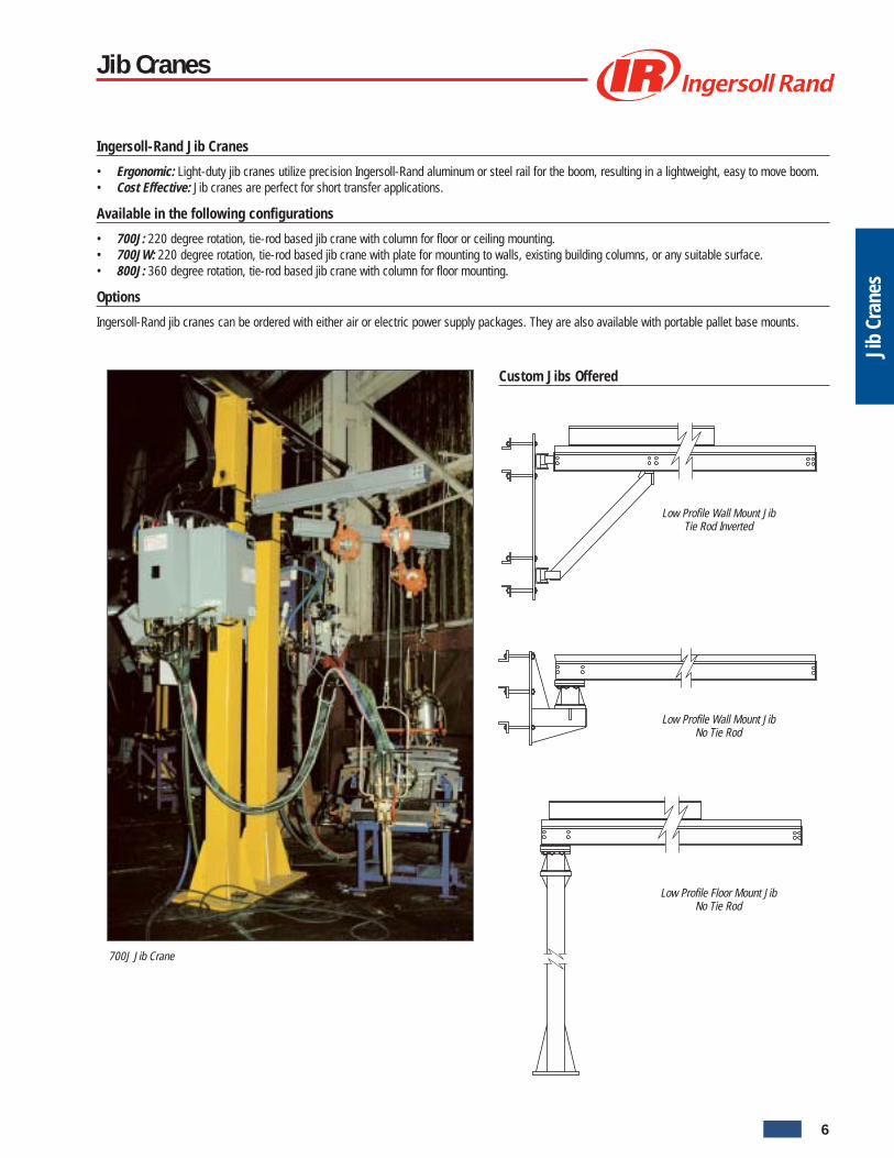
Ingersoll-Rand Jib Cranes
• Ergonomic: Light-duty jib cranes utilize precision Ingersoll-Rand aluminum or steel rail for the boom, resulting in a lightweight, easy to move boom.• Cost Effective: Jib cranes are perfect for short transfer applications.
Available in the following configurations
• 700J: 220 degree rotation, tie-rod based jib crane with column for floor or ceiling mounting.• 700JW: 220 degree rotation, tie-rod based jib crane with plate for mounting to walls, existing building columns, or any suitable surface.• 800J: 360 degree rotation, tie-rod based jib crane with column for floor mounting.
Options
Ingersoll-Rand jib cranes can be ordered with either air or electric power supply packages. They are also available with portable pallet base mounts.
700J Jib Crane
Jib Cranes
Custom Jibs Offered
Low Profile Wall Mount JibTie Rod Inverted
Low Profile Wall Mount JibNo Tie Rod
Low Profile Floor Mount JibNo Tie Rod
6
Untitled-1 5/8/06, 11:58 AM9

Jib
Cran
es
Boom
U
OAH
Boom + 9.5” (241.3 mm) = LightBoom + 10.5” (266.7 mm) = MediumBoom + 10.5” (266.7 mm) = Heavy)
700J
OAH = Overall heightU = Underclearance
Jib Cranes700J
For applications not covered on this sheet or pallet based applications, consult the factory.Dimensional Notes:ZRA1 (Light)U” Standard columns 6 x 6 x 1/4 in. designed for 144 in. (12 ft/3.7 m) under clearance or less.P Base plate 3/4 x 18 x 18 in., 8-holes 7/8 in. diameter on a 16 in. (406.4 mm) bolt circle.
3/4 in. stud anchors or bolts are to be supplied by the customer.ZRA2 (Medium)U” Standard columns 8 x 8 x 1/4 in. designed for 144 in. (12 ft/3.7 m) under clearance or less.P Base plate 3/4 x 24 x 24 in., 8-holes 7/8 in. diameter on a 20 in. (508 mm) bolt circle.
3/4 in. stud anchors or bolts are to be supplied by the customer.ZRA2 (Heavy)U” Standard columns 8 x 8 x 1/2 in. designed for 144 in. (12 ft/3.7 m)under clearance or less.P Base plate 3/4 x 24 x 24 in., 8-holes 7/8 in. diameter on a 20 in. (508 mm) bolt circle.
3/4 in. stud anchors or bolts are to be supplied by the customer.ZRS2 (Medium)U” Standard columns 8 x 8 x 1/4 in. designed for 144 in. (508 mm) under clearance or less.P Base plate 3/4 x 24 x 24 in., 8-holes 7/8 in. diameter on a 20 in. (508 mm) bolt circle.
3/4 in. stud anchors or bolts are to be supplied by the customer.ZRS3 (Heavy)U” Standard columns 8 x 8 x 1/2 in. designed for 144 in. (508 mm under clearance or less.P Base plate 3/4 x 24 x 24 in., 8-holes 7/8 in. diameter on a 20 in. (508 mm) bolt circle.
3/4 in. stud anchors or bolts are to be supplied by the customer.
ZRA1 Boom Type 2200 Rotation (Light)Part no. Boom Capacity OAH = U + Weight
ft m lbs kg in. mm lbs kg
7090JA1F04144 4 1.22 900 408.2 38 965 375 170.5
7061JA1F06144 6 1.83 610 276.7 38 965 375 174.1
7046JA1F08144 8 2.44 460 208.7 38 965 391 177.7
7037JA1F10144 10 3.05 370 167.8 38 965 399 181.4
7030JA1F12144 12 3.66 300 136.1 38 965 407 185
7026JA1F14144 14 4.27 260 117.9 38 965 414 188.2
7023JA1F16144 16 4.88 230 104.3 38 965 423 192.3
7020JA1F18144 18 5.49 200 90.7 38 965 431 195.9
7016JA1F20144 20 6.1 160 72.6 38 965 439 199.5
ZRA2 Boom Type 2200 Rotation (Medium)Part no. Boom Capacity OAH = U + Weight
ft m lbs kg in. mm lbs kg
7200JA2F04144 4 1.22 2000 907.2 39 991 660 300
7140JA2F06144 6 1.83 1400 635 39 991 675 306.8
7105JA2F08144 8 2.44 1050 476.3 39 991 690 313.6
7080JA2F10144 10 3.05 800 362.9 39 991 705 320.5
7070JA2F12144 12 3.66 700 317.5 39 991 720 327.3
7060JA2F14144 14 4.27 600 272.2 39 991 735 334.1
7050JA2F16144 16 4.88 500 226.8 39 991 782 355.5
7045JA2F18144 18 5.49 450 204.1 39 991 797 362.3
7040JA2F20144 20 6.1 400 181.4 39 991 812 369.1
ZRA2 Boom Type 2200 Rotation (Heavy)Part no. Boom Capacity OAH = U + Weight
ft m lbs kg in. mm lbs kg
7200JA2F06144 6 1.83 2000 907.2 39 991 925 420.5
7200JA2F08144 8 2.44 2000 907.2 39 991 940 427.3
7160JA2F10144 10 3.05 1600 725.7 39 991 955 434.1
7135JA2F12144 12 3.66 1350 612.3 39 991 970 441
7115JA2F14144 14 4.27 1150 521.6 39 991 985 447.7
7100JA2F16144 16 4.88 1000 453.6 51 1295 1000 454.5
7080JA2F18144 18 5.49 800 362.9 51 1295 1065 484.1
7065JA2F20144 20 6.1 650 294.8 51 1295 1080 491
ZRS2 Boom Type 2200 Rotation (Medium)Part no. Boom Capacity OAH = U + Weight
ft m lbs kg in. mm lbs kg
7200JS2F04144 4 1.22 2000 907.2 39 961 660 300
7140JS2F06144 6 1.83 1400 635 39 961 675 306.8
7105JS2F08144 8 2.44 1050 476.3 39 961 690 313.6
7085JS2F10144 10 3.05 850 385.6 39 961 705 320.5
7070JS2F12144 12 3.66 700 317.5 39 961 720 327.3
7060JS2F14144 14 4.27 600 272.2 39 961 735 334.1
7053JS2F16144 16 4.88 530 240.4 39 961 782 355.5
7048JS2F18144 18 5.49 480 217.7 39 961 797 362.3
7042JS2F20144 20 6.1 420 190.5 39 961 812 369.1
ZRS3 Boom Type 2200 Rotation (Heavy)Part no. Boom Capacity OAH = U + Weight
ft m lbs kg in. mm lbs kg
7200JS3F04144 4 1.22 2000 907.2 40.38 1026 910 413.6
7200JS3F06144 6 1.83 2000 907.2 40.38 1026 927 421.4
7200JS3F08144 8 2.44 2000 907.2 40.38 1026 944 429.1
7160JS3F10144 10 3.05 1600 725.7 40.38 1026 961 436.8
7135JS3F12144 12 3.66 1350 612.3 40.38 1026 978 444.5
7115JS3F14144 14 4.27 1150 521.6 40.38 1026 995 452.3
7100JS3F16144 16 4.88 1000 453.6 52.38 1330 1062 482.7
7080JS3F18144 18 5.49 800 362.9 52.38 1330 1079 490.5
7060JS3F20144 20 6.1 600 272.2 52.38 1330 1096 498.2
Base PlateConfiguration
7
Untitled-1 5/8/06, 11:58 AM10

Jib
Cran
es
OAH = Overall heightU = Underclearance
OAH = Overall heightU = Underclearance
ZRA1 and ZRS2 ZRA2 and ZRS3
Jib Cranes700JW
ZRA1 Boom Type Wall Mount (Light)Part no. Boom Capacity OAH Weight
ft m lbs kg in. mm lbs kg
7100JA1W04 4 1.22 1000 453.6 44 1118 120 54.5
7100JA1W06 6 1.83 1000 453.6 44 1118 131 59.5
7100JA1W08 8 2.44 1000 453.6 44 1118 142 64.5
7080JA1W10 10 3.05 800 362.9 44 1118 153 69.5
7050JA1W12 12 3.66 500 226.8 44 1118 164 74.5
7036JA1W14 14 4.27 360 163.3 44 1118 175 79.5
7026JA1W16 16 4.88 260 117.9 44 1118 186 84.5
7020JA1W18 18 5.49 200 90.7 44 1118 197 89.5
7016JA1W20 20 6.1 160 72.6 44 1118 208 94.5
ZRS3 Boom Type Wall Mount (Heavy)Part no. Boom Capacity OAH Weight
ft m lbs kg in. mm lbs kg
7200JS3W04 4 1.22 2000 907.2 44 1118 146 66.4
7200JS3W06 6 1.83 2000 907.2 44 1118 166 75.5
7200JS3W08 8 2.44 2000 907.2 44 1118 186 84.5
7190JS3W10 10 3.05 1900 861.8 44 1118 206 93.6
7160JS3W12 12 3.66 1600 725.7 44 1118 226 102.7
7135JS3W14 14 4.27 1350 612.3 44 1118 246 111.8
7100JS3W16 16 4.88 1000 453.6 56 1423 278 126.4
7080JS3W18 18 5.49 800 362.9 56 1423 322 146.6
7060JS3W20 20 6.1 600 272.2 56 1423 366 166.4
ZRA2 Boom Type Wall Mount (Heavy)Part no. Boom Capacity OAH Weight
ft m lbs kg in. mm lbs kg
7200JA2W04 4 1.22 2000 907.2 44 1118 145 65.9
7200JA2W06 6 1.83 2000 907.2 44 1118 154 70
7200JA2W08 8 2.44 2000 907.2 44 1118 181 82.3
7190JA2W10 10 3.05 1900 861.8 44 1118 199 90.5
7160JA2W12 12 3.66 1600 725.7 44 1118 217 98.6
7135JA2W14 14 4.27 1350 612.3 44 1118 235 106.8
7100JA2W16 16 4.88 1000 453.6 56 1423 266 120.9
7080JA2W18 18 5.49 800 362.9 56 1423 310 140.9
7060JA2W20 20 6.1 600 272.2 56 1423 354 160.9
ZRS2 Boom Type Wall Mount (Medium)Part no. Boom Capacity OAH Weight
ft m lbs kg in. mm lbs kg
7200JS2W04 4 1.22 2000 907.2 44 1118 145 65.9
7200JS2W06 6 1.83 2000 907.2 44 1118 163 74.1
7200JS2W08 8 2.44 2000 907.2 44 1118 181 82.3
7190JS2W10 10 3.05 1900 861.8 44 1118 199 90.5
7160JS2W12 12 3.66 1600 725.7 44 1118 217 98.6
7100JS2W14 14 4.27 1000 453.6 44 1118 235 106.8
7080JS2W16 16 4.88 800 362.9 56 1423 266 120.9
7060JS2W18 18 5.49 600 272.2 56 1423 310 140.9
7045JS2W20 20 6.1 450 204.1 56 1423 354 160.9
5/8” (16 mm) Plate
Boom
Section A
ZRA212” (304.8 mm)ZRS312” (304.8 mm)Ref. ZRA28” (203.2 mm)Ref. ZRS38” (203.2 mm)
Section A
OAH
1/2” (13 mm) Plate
Boom
Section A
Section A
OAH
ZRA110” (254 mm)ZRS210” (254 mm)Ref. ZRA16” (152.4 mm)Ref. ZRS27” (177.8 mm)
8
Untitled-1 5/8/06, 11:58 AM11

Jib
Cran
es
How to order
Jib Crane Model Driver
Rail typeS2
A1 = ZRA1A2 = ZRA2S2 = ZRS2S3 = ZRS3
Style7
78
Underclearance144in mm
144 = 144 3657.6
Boom length08
ft m04 = 4 1.2206 = 6 1.8308 = 8 2.4410 = 10 3.0512 = 12 3.6614 = 14 4.2716 = 16 4.8818 = 18 5.4920 = 20 6.10
JibJ
Capacity080lbs kg
080 = 080 36.4in 10s of lbs
Mount typeF
F = FloorW = Wall
OAH = Overall heightU = Underclearance
OAH
U
Boom
Boom + 5-1/8" (130 mm)
800J
Jib Cranes800J
For applications not covered on this sheet or pallet based applications, consult the factory.Dimensional Notes:ZRA1, ZRA2 and ZRS2 (Medium)U” Standard columns 6 x 6 x 1/4 in. designed for 144 in. (12 ft/3.7 m) under clearance or less.P Base plate 3/4 x 18 x 18 in., 8-holes 7/8 in. diameter on a 16 in. (406.4 mm) bolt circle.
3/4 in. stud anchors or bolts are to be supplied by the customer.
ZRA2 Boom Type 3600 RotationPart no. Boom Capacity OAH = U + Weight
ft m lbs kg in. mm lbs kg
8082JA2F04144 4 1.22 820 371.9 39.28 997.7 419 190.5
8055JA2F06144 6 1.83 550 249.5 39.28 997.7 435 197.7
8041JA2F08144 8 2.44 410 186 39.28 997.7 451 205
8033JA2F10144 10 3.05 330 149.7 39.28 997.7 467 212.3
8027JA2F12144 12 3.66 270 122.5 39.28 997.7 483 219.5
8023JA2F14144 14 4.27 230 104.3 39.28 997.7 499 226.8
8020JA2F16144 16 4.88 200 90.7 39.28 997.7 515 234.1
8018JA2F18144 18 5.49 180 81.6 39.28 997.7 531 241.4
8016JA2F20144 20 6.1 160 72.6 39.28 997.7 547 248.6
ZRA1 Boom Type 3600 RotationPart no. Boom Capacity OAH = U + Weight
ft m lbs kg in. mm lbs kg
8082JA1F04144 4 1.22 820 371.9 38.09 967.5 415 188.6
8055JA1F06144 6 1.83 550 249.5 38.09 967.5 423 192.3
8041JA1F08144 8 2.44 410 186 38.09 967.5 431 195.9
8033JA1F10144 10 3.05 330 149.7 38.09 967.5 439 199.5
8027JA1F12144 12 3.66 270 122.5 38.09 967.5 447 203.2
8023JA1F14144 14 4.27 230 104.3 38.09 967.5 455 206.8
8020JA1F16144 16 4.88 200 90.7 38.09 967.5 463 210.5
8018JA1F18144 18 5.49 180 81.6 38.09 967.5 471 214.1
8016JA1F20144 20 6.1 160 72.6 38.09 967.5 479 217.7
ZRS2 Boom Type 3600 RotationPart no. Boom Capacity OAH = U + Weight
ft m lbs kg in. mm lbs kg
8082JS2F04144 4 1.22 820 371.9 39.15 994.4 419 190.5
8055JS2F06144 6 1.83 550 249.5 39.15 994.4 435 197.7
8041JS2F08144 8 2.44 410 186 39.15 994.4 451 205
8033JS2F10144 10 3.05 330 149.7 39.15 994.4 467 212.3
8027JS2F12144 12 3.66 270 122.5 39.15 994.4 483 219.5
8023JS2F14144 14 4.27 230 104.3 39.15 994.4 499 226.8
8020JS2F16144 16 4.88 200 90.7 39.15 994.4 515 234.1
8018JS2F18144 18 5.49 180 81.6 39.15 994.4 531 241.4
8016JS2F20144 20 6.1 160 72.6 39.15 994.4 547 248.6
Air supply kitsSize Part no.
3/8” 90027
1/2” 90028
Note:Includes filter regulator assembly with brackets, tagline assembly, and coiled hose
Base PlateConfiguration
9
Untitled-1 5/8/06, 11:58 AM12

Inte
lift
The Intelift control module is a compact, integral element of the balancer itself. No cumbersome remote add-ons are necessary. It providessimple programming of functions with a keypad and indicator lights, and confirms settings with an easy-to-read display window. The closedloop feedback system delivers responsive motion control and a wide range of application options for vehicle assembly, general industry,beverage and warehouse as well as textile and electronics industries worldwide.
Best-In-Class Intelift Control System
Self-balance features enables intuitive speed control for different weights. Float mode allows the float capability through out the entirelength of travel by maintaining constant pressure in the balancer using a pressure sensor. Position control through the Dump mode featureis achieved with closed loop feedback system. Smart drop feature allows lowering of the load until only the weight of the end effector issupported, reducing the sequence of operations. Part present feature enables clamping of parts in poor visibility. When used with vacuumcup devices, reduces air consumption and noise level. Up control disable feature ensures parts are securely clamped before permittingloads to be lifted. The 3 speed select feature further enhances the flexibility and productivity of the Intelift system.
“DOWN” Speed Indicator Lights
“UP” Speed Indicator Lights
Intelift Indicator Light
“ON” - “OFF” Circuit Breaker Switch
LC Display Window
Power Connection
Power “ON” Indicator Light
Shift
Set-Up
Next
Up>
Down<
Control HandleCable Connection
Set-up keypad
10
Untitled-1 5/8/06, 11:58 AM13

Inte
lift
New Ergonomically Superior Control Handle
The unique design of the control handle provides multi functional capabilities, reducing the sequence of operations and cycle time.The control handle is available in two styles:
• Pendant control handle• Force Sensing control handle (no up/down buttons)
Two tier design for primary andsecondary controls
– Textured rubber grip
– Ergonomically shaped andoptimized grip accommodatemost hand sizes, as well asright and left–handedoperators
– Intuitive, comfortable andergonomic design
Intelift featureselection button
– Light indicators on secondary controls
– Color coded buttons with standard symbols
– 3-speed select button
– Easy access controls• Clamp/Unclamp button• Up/Down rocker switch
– No up/down buttons necessary on the loadcell based control handle
Safety Cost SavingsFlexibility Ergonomics Productivity
Emergency stop button
Common mounting interface forhandling devices
Electronic endeffector interface
11
Untitled-1 5/8/06, 11:58 AM14

Inte
lift
Robust design for continuous duty with minimalmaintenance
Simple operation forreduced trainingtime and costs
Quick installation and set-up
Float Mode Functions• Precise Positioning• Allows part manipulation• Can float the entire length of travel
3 Speed Select• Offers flexibility to the operator• Offers application flexibility• Allows operator training at lower speeds
Smart Drop Features• Pre-release interlock enhancement• Reduces sequence of operations
Patented Z-BrakeOther patents pending
Intelift Intelligent Lifting System
A complete range of end effectors can be used with Intelift controls for greater efficiency, from the simplest to the most complex device.The Intelift unit incorporates a fully grounded, fault-protected electrical system, with fused circuits and memory that automatically reinstatesfunction selections following a power interruption. In every respect, the Ingersoll-Rand Intelift air balancer is an essential solution for a moreproductive workplace, empowering individuals to work comfortably and effectively, significantly contributing to product and process quality.
Safety Cost SavingsFlexibility Ergonomics Productivity
12
Untitled-1 5/8/06, 11:58 AM15

Inte
lift
Intelift Intelligent Lifting System
The engine handling device shown uses the unique features of theIntelift balancer. Features include: Auto Clamp, Interlock, Upcontrol disable, weight sensing with automatic alarm, and keyedlock out.
Error proof assembly:The device digitally displays the weight of the part picked up. Device will not allowthe operator to move the part if not clamped properly. The key allows the operatorthe ability to lock the device. Allows 100% visual inspection of the assembly.
The warehouse handling device shown is known for it’s versatility. The device mimics the human motion of picking a part and placing it. The same devicecan be used to pick up parts such as totes, trays, boxes, and milk crates. The second picture shows the same device lifting a different part. The selfbalance feature allows the same device to pick up parts of diffrent weights and sizes.
ProductivityThe intelligent lifting systems shown above demonstrates speed and easeof use with minimal training required. The closed loop feedback systemdelivers responsive motion control and a wide range of application options.
Safety Cost SavingsFlexibility Ergonomics Productivity
Call 1-800-347-7047
for distributors in your area
13
Untitled-1 5/8/06, 11:59 AM16
Inte
lift
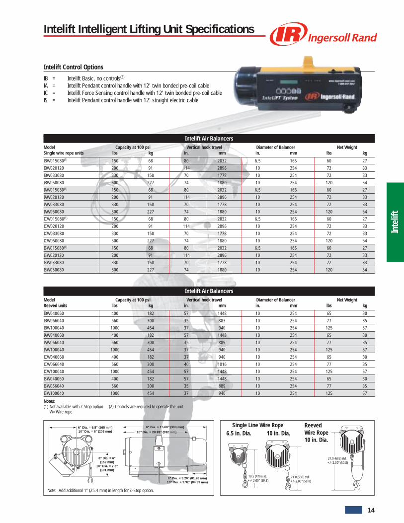
Intelift Control Options
IB = Intelift Basic, no controls(2)
IA = Intelift Pendant control handle with 12' twin bonded pre-coil cableIC = Intelift Force Sensing control handle with 12' twin bonded pre-coil cableIS = Intelift Pendant control handle with 12' straight electric cable
Single Line Wire Rope6.5 in. Dia. 10 in. Dia.
Intelift Intelligent Lifting Unit Specifications
Intelift Air BalancersModel Capacity at 100 psi Vertical hook travel Diameter of Balancer Net WeightSingle wire rope units lbs kg in. mm in. mm lbs kg
IBW015080(1) 150 68 80 2032 6.5 165 60 27
IBW020120 200 91 114 2896 10 254 72 33
IBW033080 330 150 70 1778 10 254 72 33
IBW050080 500 227 74 1880 10 254 120 54
IAW015080(1) 150 68 80 2032 6.5 165 60 27
IAW020120 200 91 114 2896 10 254 72 33
IAW033080 330 150 70 1778 10 254 72 33
IAW050080 500 227 74 1880 10 254 120 54
ICW015080(1) 150 68 80 2032 6.5 165 60 27
ICW020120 200 91 114 2896 10 254 72 33
ICW033080 330 150 70 1778 10 254 72 33
ICW050080 500 227 74 1880 10 254 120 54
ISW015080(1) 150 68 80 2032 6.5 165 60 27
ISW020120 200 91 114 2896 10 254 72 33
ISW033080 330 150 70 1778 10 254 72 33
ISW050080 500 227 74 1880 10 254 120 54
Intelift Air BalancersModel Capacity at 100 psi Vertical hook travel Diameter of Balancer Net WeightReeved units lbs kg in. mm in. mm lbs kg
IBW040060 400 182 57 1448 10 254 65 30
IBW066040 660 300 35 883 10 254 77 35
IBW100040 1000 454 37 940 10 254 125 57
IAW040060 400 182 57 1448 10 254 65 30
IAW066040 660 300 35 889 10 254 77 35
IAW100040 1000 454 37 940 10 254 125 57
ICW040060 400 182 37 940 10 254 65 30
ICW066040 660 300 40 1016 10 254 77 35
ICW100040 1000 454 57 1448 10 254 125 57
ISW040060 400 182 57 1448 10 254 65 30
ISW066040 660 300 35 889 10 254 77 35
ISW100040 1000 454 37 940 10 254 125 57
Notes:(1) Not available with Z Stop option (2) Controls are required to operate the unit
W=Wire rope
6" Dia. = 3.20" (81.28 mm)10" Dia. = 3.32" (84.33 mm)
6" Dia. = 15.68" (398 mm)
10" Dia. = 20.93" (532 mm)6" Dia. = 6.5" (165 mm)10" Dia. = 8" (203 mm)
6" Dia. = 6" (152 mm)
10" Dia. = 7.5" (191 mm)
18.5 (470) std. +/- 2.00" (50.8)
21.0 (533) std. +/- 2.00" (50.8)
27.0 (686) std. +/- 2.00" (50.8)
ReevedWire Rope10 in. Dia.
Note: Add additional 1” (25.4 mm) in length for Z-Stop option.
14
Untitled-1 5/8/06, 11:59 AM17

Inte
lift
How to Order
Example: IAW020120A21SP IA W 020 120 A2 1 S P
Intelift Control Options
IB = Intelift Basic, no controlsIA = Intelift Pendant control handle with 12' twin bonded pre-coil cableIC = Intelift Force Sensing control handle with 12' twin bonded pre-coil cableIS = Intelift Pendant control handle with 12' straight electric cable
Type
W = Wire rope
Capacity
020 = 200 lbs (91kg) [for available capacities, refer to model number tables]
Travel
120 = 120 inches (3048mm) [for available travel, refer to model number tables]
Suspension Options
00 = No SuspensionS2 = ZRS2 steel railS3 = ZRS3 steel railHM = Hook MountTR = T-Rail / I-BeamAT = ZRAT Aluminum railA1 = ZRA1 Aluminum railA2 = ZRA2 Aluminum railE4 = ETA-4 Aluminum RailE8 = ETA-8 Aluminum RailG1 = Gorbel 1000# Alum. Series TrackG2 = Gorbel 1000# Steel. Series TrackK1 = KBK1 Steel RailK2 = KBK2 and KBK2L Steel RailK3 = 4” Aluminum, KnightK4 = 8” Aluminum, KnightK5 = 8” Aluminum Anti Kick Back, KnightK6 = 4” Steel, KnightE7 = 6” Steel, KnightK8 = 7” Steel, Knight
Voltage Options
1 = 115V 50/60Hz 1PH2 = 230V 50/60Hz 1PH
Z-Stop Option
0 = NoneS = Z-Stop
Power Cord Option
0 = NoneP = 6’ Power Cord
15
Untitled-1 5/8/06, 11:59 AM18

Inte
lift
NOTES
16
Untitled-1 5/8/06, 11:59 AM19

Bala
ncer
s
The Strength Behind Material Handling Technology
Meeting the needs of today’s material handling applications requiresan ergonomic lift assist that interacts with the operator. TheBalancer offers lifting solutions to meet these needs through floatand built in safety features.
Balancer Advantage
Precise, strain-free positioning – Float leaves both hands free to raise,lower, or shift the load with virtually no resistance. No more “hoist control”hit-and-miss spotting.Simple adjustment – Clear access to air-flow calibration controls allowsquick, easy adjustment of the float.Low air consumption – Approximately 1/8 cfm required per cycle (50times less than an air hoist), means very low energy costs.Clean, oil-free operation – Pre-lubricated design – Eliminates air linelubrication and oil mist exhaust. It’s ideal for food processing and cleanmanufacturing environments.Rugged reliability – for continuous duty with minimal maintenance, theBalance Air delivers cost effective performance.
Safety is Standard
Built-in overload protection – The load being lifted can never exceed theunit’s maximum rated capacity for a given air pressure. Maximum capacityis rated at 100 psig and actual capacity is linearly proportional to actualpressure. For example, at 70 psig the unit can only lift up to 70% of itsmaximum capacity.Minimal cable recoil due to loss of load – If the load is accidentally lost,a spring-loaded centrifugal brake (Z brake) automatically stops rapidupward cable travel.
Versatile configuration
Wide range of capacities – Balancers are rated from 50 to 2,000 pounds(22 to 909 kg) maximum, with lower capacity units adjustable for loads aslow as 2 pounds (.9 kg). Tandem units handle larger loads.Added protection – The optional Z Stop offers protection against thedrifting of loads in the event the main air supply is lost.Cable travel – The range of up/down movement varies from 40 to 120inches, (1016 to 3048 mm) depending on the model.Controls – ZA (pendant) controls let you handle varying loads; a BA(single) balance control is ideal for a constant load, and an EA for 2 loads.Mounting – Suspension kits for Ingersoll-Rand and other enclosed trackmanufacturers as well as I-Beam, patented track, and hook mount.CE Certification – Meets the requirements for the European Community.
Pneumatic Balancers50 to 2000 lbs (22 to 909 kg) Capacity
Balancer with ZA pendent control
Available in 6.5 inch (165.1 mm) and 10inch (254 mm) can sizes
Z Stop: The optional Z Stop is a patentpending device that will eliminate the down-drift of suspended loads or tools during shutdown or at night when the air supply is shutoff. The Z Stop will stop drift within 6 inches(152.4 mm) and put the Balance Air into amechanically locked position preventingdamage to tools or objects below thesuspended load. Available for use on all10 inch (254 mm) diameter units.
17
Untitled-1 5/8/06, 11:59 AM20

Bala
ncer
s
Anti-friction ballscrew: Createssmooth rotationpath for the cablereel.
Injection molded reel: Engineeredplastic for excellent durability andwear resistance.
Rugged steel housing: All steel housingfor added durability
Suspension lugs: Fits all Ingersoll-Randsuspensions and most trolleys from othermanufacturers.
Heavy-duty thrust bearing:Absorbs piston force andtransfers smooth reel rotationover the ball screw.
Low-friction cable guide(not shown): Ensures smoothcable feed on and off the reel.
Air chamber and piston: Forms the heart of the unit. Air entering thechamber pushes the piston to rotate the spool, wind the cable, and liftthe load. Exhausting air lowers the load. Regulating this flow balancesthe load, creating a zero gravity float.
Z Brake Safety Retraction System:(Patent No. 5,522,581)Prevents violent retraction in the event of asudden release or loss of load. The brakewill also eliminate excessive upwardacceleration of a no load hook when the“up” button is employed to full depression.This system is available on all units (except50 lb/22 kg units) equipped with eithercable or chain.
OptionalZ Stoplocation
Pneumatic Balancers50 to 2000 lbs (22 to 909 kg) Capacity
18
Bala
ncer
s
Untitled-1 5/8/06, 11:59 AM21

Bala
ncer
s
Balancer withZA pendent control
Balancer withEA Hi load, Lo load,No load control
Balancer withBA Z-Servo control
Control and Suspension Options
(BA) Single Balance Control: A Balancer equipped with the (BA)Single Balance control is an excellent alternative to traditional springbalancers.The balance range of a single capacity Balancer isequivalent to that of 10 different capacity spring balancers with themain difference being that the Balancer maintains constant tensionthroughout its full range of travel.
Suitable for:
• Tool Balancing• Weld Gun Suspension• Fixture Suspension
Pneumatic Balancers50 to 2000 lbs (22 to 909 kg) Capacity
(ZA) Pendent Control: The (ZA) Pendent Control is designed for highspeed precision handling of variable weight loads. Up/Down movement isaccomplished through the use of an ergonomically designed pendent withlow-effort, color-coded thumb levers. After positioning the load with thependent control, the unit defaults into a balance float condition allowingthe operator up to 18 inches (457.2 mm) of movement by pushing the cordup or down by hand.(EA) Hi, Lo, Un Load Control: Balancers equipped with the (EA) controlare designed to excel in high speed, constant weight, repetitive partshandling operations. The control positions are thumb actuated and areused to switch the unit to accommodate different load modes as required.
These are as follows:
HILOAD: Used to pick up or balance the maximum weight load.LOLOAD: Used to balance, lower, and precisely position the load.UNLOAD: Used to release and balance the empty hook.
19
Untitled-1 5/8/06, 11:59 AM22

Bala
ncer
s
Balancer with I-Beam/Patented Track trolley mountconfiguraton
Balancer with hook mount configuration
The 50 lb Tool Series
This air unit offers an incredible 2 to 50 pound (.9 to 22 kg) loadcapacity. A range our competitors achieve only with numerousmodels designed for individual load weight. Designedand manufactured in the United States, the 50 lbBalancer offers numerous other benefits over springoperated units, including our exclusive flotationfeature.
Standard Features
Performance – Float action provides ease of verticaltravel, eliminating tension on load making positioningcapability far superior.Versatility – No need to change model when makingtool change; one model (BAW005060) covers entire 50lb (22 kg) range.Headroom – Requires only 20 inches (508 mm) from bottom of railto bottom of hook.Adjustment – Simple adjustment in seconds by means of externalregulator.Sequencing – Can be sequenced via air signal to perform timed or“stepped” operation.Maintenance – Virtually maintenance-free. Normal maintenance can bedone in place on the rail.Installation – Requires air hookup (can be tied into tooling air supply).
Balancer with enclosed rail trolley mountconfiguration
Pneumatic Balancers50 to 2000 lbs (22 to 909 kg) Capacity
EZ Grip Ergonomic Handle
Quality manufactured handle by Ingersoll-Rand, the world leader in ergonomicallysound material handling equipment. Rugged,durable construction handle with threemounting options. The handle can be usedas a pendent control, rigid mount. Thishandle can be used on most air actuateddevices, including air hoists, and can beoperated with or without gloves.
20
Untitled-1 5/8/06, 11:59 AM23

Bala
ncer
s 18.5 (470) std. +/- 2.00" (50.8)
21.0 (533) std. +/- 2.00" (50.8)
8.50(216)
4.25(108)
A
4.06(103)
4.2(107)
6.5 inch (165.1 mm) Diameter Can 10 inch (254 mm) Diameter Can 200, 350 and 500 lb Balancer
Note:(1) 1 inch (25.4 mm) dimension for
optional Z Stop only.(2) 3.75 inch (95.25 mm) dimension for
EA regulator/elbow fitting (largest stack-up)
Dimensions
15.68(398)
150 lb(68.2 kg)
15.68(398)
200 lb(90.9 kg)325 lb(147.7 kg)350 lb(159.1 kg)
1.0 (25.4)See Note (1)
3.75 (95)See Note (2)
20.93(532)
500 lb(227.3 kg)
Pneumatic Balancers50 to 2000 lbs (22 to 909 kg) Capacity
DimensionsLoad capacity Type “A” Dimensions
lbs kg in. mm
150 68 W 2.85 72.4
200 90 W 4.10 104.1
350 158 W 2.85 72.4
350 158 C 2.79 70.9
500 227 W 3.62 91.9
500 227 C 3.51 89.2
Note:For all drawings, dimensions in ( ) are in mm
5.62(143)
2.81(71.4)
A
2.81(71.4)
4.2(107)
150 lb Balancer
21
Untitled-1 5/8/06, 11:59 AM24

Bala
ncer
s
27.0 (686) std. +/- 2.00" (50.8)
36.5 (927) std. +/- 2.00" (50.8) 41.5 (1054) std.
+/- 2.00" (50.8)
28.0 (711) std. +/- 2.00" (50.8)
39.0 (991) std. +/- 2.00" (50.8)
33 .0 (838) std. +/- 2.00" (50.8)
Tandem Reeved Tandem Reeved
Single with Servo Reeved with Servo Tandem Reeved with Servo
Pneumatic Balancers50 to 2000 lbs (22 to 909 kg) Capacity
Dimensions
Note:For all drawings, dimensions in ( ) are in mm
22
Untitled-1 5/8/06, 11:59 AM25
Bala
ncer
s
Pneumatic Balancers50 to 2000 lbs (22 to 909 kg) Capacity
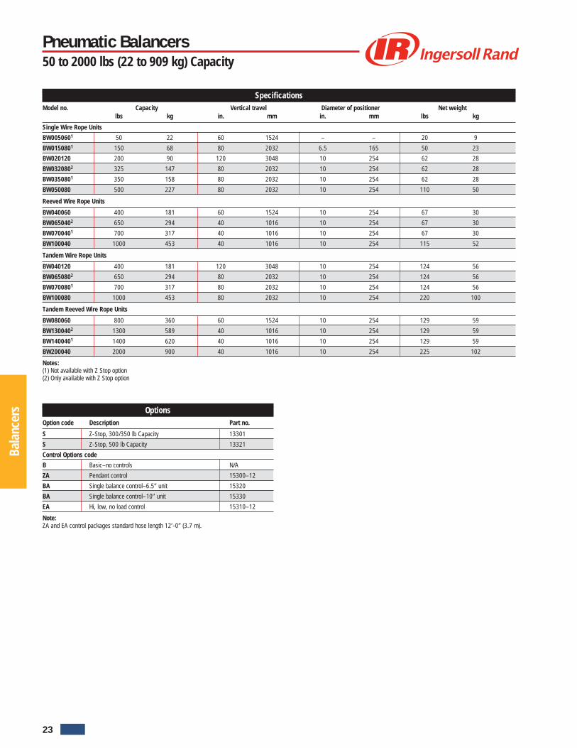
SpecificationsModel no. Capacity Vertical travel Diameter of positioner Net weight
lbs kg in. mm in. mm lbs kg
Single Wire Rope Units
BW0050601 50 22 60 1524 – – 20 9
BW0150801 150 68 80 2032 6.5 165 50 23
BW020120 200 90 120 3048 10 254 62 28
BW0320802 325 147 80 2032 10 254 62 28
BW0350801 350 158 80 2032 10 254 62 28
BW050080 500 227 80 2032 10 254 110 50
Reeved Wire Rope Units
BW040060 400 181 60 1524 10 254 67 30
BW0650402 650 294 40 1016 10 254 67 30
BW0700401 700 317 40 1016 10 254 67 30
BW100040 1000 453 40 1016 10 254 115 52
Tandem Wire Rope Units
BW040120 400 181 120 3048 10 254 124 56
BW0650802 650 294 80 2032 10 254 124 56
BW0700801 700 317 80 2032 10 254 124 56
BW100080 1000 453 80 2032 10 254 220 100
Tandem Reeved Wire Rope Units
BW080060 800 360 60 1524 10 254 129 59
BW1300402 1300 589 40 1016 10 254 129 59
BW1400401 1400 620 40 1016 10 254 129 59
BW200040 2000 900 40 1016 10 254 225 102
Notes:(1) Not available with Z Stop option(2) Only available with Z Stop option
OptionsOption code Description Part no.
S Z-Stop, 300/350 lb Capacity 13301
S Z-Stop, 500 lb Capacity 13321
Control Options code
B Basic–no controls N/A
ZA Pendant control 15300–12
BA Single balance control–6.5” unit 15320
BA Single balance control–10” unit 15330
EA Hi, low, no load control 15310–12
Note:ZA and EA control packages standard hose length 12’-0” (3.7 m).
23
Untitled-1 5/8/06, 12:00 PM26

Bala
ncer
s
How to order
Pneumatic Balancers Model Driver
TypeW
W = Wire Rope
Travel120
120 = 120 inchesTravel distance isdetermined by seriesand capacity, and isnot a variable option.See model no. inspecifications chart.Example: BW020120
ControlB
B = Basic, no controlsZA = Pendent controlBA = Single balance
controlEA = Hi, Low, No load
control
SuspensionS2
00 = No suspensionS2 = ZRS2 steel railS3 = ZRS3 steel railHM = Hook mountTR = T-Rail / I-BeamAT = ZRAT aluminum railA1 = ZRA1 aluminum railA2 = ZRA2 aluminum railE4 = ETA-4 aluminum railE8 = ETA-8 aluminum railK1 = KBK1 steel railK2 = KBK2 steel railG1 = Gorbel 1000# Alum. Series TrackG2 = Gorbel 1000# Steel Series TrackK3 = 4” AluminumK4 = 8” AluminumK5 = 8” Aluminum Anti Kick BackK6 = 4” SteelK7 = 6” SteelK8 = 7” Steel
OptionsS
S = Z-Stop
Capacity020
Wire lbs kg0051 = 50 220151 = 150 68020 = 200 900322 = 325 1470351 = 350 158040 = 400 181050 = 500 2270652 = 650 2940701 = 700 317080 = 800 362100 = 1000 4531302 = 1300 5891401 = 1400 365200 = 2000 907
Notes:(1) Not available with Z-Stop option(2) Only available with Z-Stop option
Pneumatic Balancers50 to 2000 lbs (22 to 909 kg) Capacity
Suspension Options (1)
Option code Description 6.5” 10” Competitor Product
00 No suspension – – NA
S2 ZRS2 steel rail 16300 16400 NA
S3 ZRS3 steel rail 16300 16400 NA
HM Hook mount 16360 16460 NA
TR T-Rail / I-Beam 16320 16420 NA
AT ZRAT aluminum rail 16355 16455 NA
A1 ZRA1 aluminum rail 16305 16405 NA
A2 ZRA2 aluminum rail 16310 16410 NA
E4 ETA-4 aluminum rail 16344 16444 Unified
E8 ETA-8 aluminum rail 16335 16435 Unified
K1 KBK1 steel rail 16325 16425 Demag
K2 KBK2 steel rail 16315 16415 Demag
G1 Gorbel 1000# Alum. Series Track 16307 16407 Gorbel
G2 Gorbel 1000# Steel Series Track 16307 16407 Gorbel
K3 4” Aluminum 16344 16444 Knight
K4 8” Aluminum 16345 16445 Knight
K5 8” Aluminum Anti Kick Back 16345 16445 Knight
K6 4” Steel 16325 16245 Knight
K7 6” Steel 16315 16415 Knight
K8 7” Steel 16315 16415 Knight
Note:(1) Tandem units require two suspension kits.
24
Untitled-1 5/8/06, 12:00 PM27

Arm
Sys
tem
s
As an alternative for reaching in, under, and around obstacles, Ingersoll-Rand Arm Systems allow an operator to precisely
and effortlessly position loads regardless of physical strength.
Fitted with one of our standard or custom End Effectors, our Manipulator Arm Systems can perform a wide variety of material handling applications. Ourfull line of Arms offer the most flexibility available on the market today.
450 Arm shown with optional clamp end effector
600 Arm shown with optional probe
700 C Arm (carriage mount) shown with optional end effector
Arm Systems
700 Series Arms
Consisting of a connecting linkage type boom that folds within itself to offera large coverage area, these arms utilize the Balance Air® lifting andbalancing unit as the lifting power.
400 Series Arms
Utilizing a parallel link design to maintain either end effector or toolorientation, these arms allow an operator to reach into an opening andmanipulate a part or tool.
600 Series Arms
Consist of a rigid vertical beam with a moving horizontal beam that is ableto reach into an opening. These arms also utilize the Balance Air® forlifting and balancing power.
• Allows for reach in and off center applications.• Variety of End Effector combinations.• Can be adapted to most rail systems.
25
Untitled-1 5/8/06, 12:00 PM28

Arm
Sys
tem
s700C ARM
B
G
H
K C
"A" Length of arm
D
L
J
700C ARM
B K C
"A" Length of arm
D
L
J
G
H
700C Series Top Mount
700C Series Bottom Mount
Arm SystemsSeries 700C
Series 700C Arm - Dimensions (inches)Capacity Top mt Bottom mt(lbs) A B C D G J K H L H L
150 72 26 34 6.78 4.25 23.75 12 13.25 8 7.75 13.53
150 84 38 34 6.78 4.25 23.75 12 13.25 8 7.75 13.53
150 96 38 46 6.78 4.25 23.75 12 13.25 8 7.75 13.53
150 108 38 46 6.78 4.25 23.75 24 13.25 8 7.75 13.53
150 120 38 46 6.78 4.25 23.75 36 13.25 8 7.75 13.53
200 72 26 34 6.78 4.25 26 12 13.25 11.13 7.75 13.66
200 84 38 34 6.78 4.25 26 12 13.25 11.13 7.75 13.66
200 96 38 46 6.78 4.25 26 12 13.25 11.13 7.75 13.66
200 108 38 46 6.78 4.25 26 24 13.25 11.13 7.75 13.66
200 120 38 46 6.78 4.25 26 36 13.25 11.13 7.75 13.66
350 72 26 34 6.78 4.25 27 12 13.25 9.96 7.75 14.47
350 84 38 34 6.78 4.25 27 12 13.25 9.96 7.75 14.47
350 96 38 46 6.78 4.25 27 12 13.25 9.96 7.75 14.47
350 108 38 46 6.78 4.25 27 24 13.25 9.96 7.75 14.47
350 120 38 46 6.78 4.25 27 36 13.25 9.96 7.75 14.47
500 72 26 34 6.78 4.25 27 12 13.25 10.63 7.75 14.16
500 84 38 34 6.78 4.25 27 12 13.25 10.63 7.75 14.16
500 96 38 46 8.5 5.5 27 12 13.25 11.38 7.75 16.63
500 108 38 46 8.5 5.5 27 24 13.25 11.38 7.75 16.63
500 120 38 46 8.5 5.5 27 36 13.25 11.38 7.75 16.63
Series 700C ArmArm Length Capacity Weight
Part No. ft m lbs kg lbs kg
70015@A**?++06# 6 1.83 150 65 218 99
70015@A**?++07# 7 2.13 150 65 237 108
70015@A**?++08# 8 2.44 150 65 248 113
70015@A**?++09# 9 2.74 150 65 263 120
70015@A**?++10# 10 3.05 150 65 275 125
70020@A**?++06# 6 1.83 200 90 248 113
70020@A**?++07# 7 2.13 200 90 267 121
70020@A**?++08# 8 2.44 200 90 278 126
70020@A**?++09# 9 2.74 200 90 278 126
70020@A**?++10# 10 3.05 200 90 304 138
70035@A**?++06# 6 1.83 350 155 257 117
70035@A**?++07# 7 2.13 350 155 279 127
70035@A**?++08# 8 2.44 350 155 290 132
70035@A**?++09# 9 2.74 350 155 290 132
70035@A**?++10# 10 3.05 350 155 316 144
70050@A**?++06# 6 1.83 500 225 271 123
70050@A**?++07# 7 2.13 500 225 290 132
70050@A**?++08# 8 2.44 500 225 328 149
70050@A**?++09# 9 2.74 500 225 350 159
70050@A**?++10# 10 3.05 500 225 367 167Note:See Page 32 - Arm model driver for key to symbols.
26
Untitled-1 5/8/06, 12:00 PM29

Arm
Sys
tem
s
701C Series Top Mount
701C Series Bottom Mount
701C
B C
H
D
L
E
"A" Length of arm
701C
B C
HDL
E
"A" Length of arm
Arm SystemsSeries 701C
Series 701C Arm - Dimensions (inches)Capacity Top mt Bottom mt(lbs) A B C D E H L H L
150 72 18 12 6.78 42 12.12 16.97 7.12 11.03
150 84 30 12 6.78 42 12.12 16.97 7.12 11.03
150 96 42 12 6.78 42 12.12 16.97 7.12 11.03
150 108 26 26 6.78 56 12.12 16.97 7.12 11.03
150 120 48 18 6.78 54 12.12 16.97 7.12 11.03
Series 701C ArmArm Length Capacity Weight
Part No. ft m lbs kg lbs kg
70115@A**?++06# 6 1.83 150 65 218 99
70115@A**?++07# 7 2.13 150 65 237 108
70115@A**?++08# 8 2.44 150 65 248 113
70115@A**?++09# 9 2.74 150 65 263 120
70115@A**?++10# 10 3.05 150 65 275 125
27
Untitled-1 5/8/06, 12:00 PM30
Arm
Sys
tem
s
713713
B
F
G
H
D
E
C
K
"A" Length of arm
713713
B
F
G
H
E
D
L
C
K
"A" Length of arm
Arm SystemsSeries 713
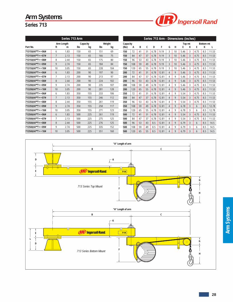
Series 713 Arm - Dimensions (inches)Capacity Top mt Bottom mt(lbs) A B C D F G H E K E K L
150 72 41 31 6.78 9.19 3 10 5.46 3 4.75 8.5 11.53
150 84 47 37 6.78 9.19 3 10 5.46 3 4.75 8.5 11.53
150 96 53 43 6.78 9.19 3 10 5.46 3 4.75 8.5 11.53
150 108 59 49 6.78 9.19 3 10 5.46 3 4.75 8.5 11.53
150 120 65 55 6.78 9.19 3 10 5.46 3 4.75 8.5 11.53
200 72 41 31 6.78 12.81 4 9 5.46 3 4.75 8.5 11.53
200 84 47 37 6.78 12.81 4 9 5.46 3 4.75 8.5 11.53
200 96 53 43 6.78 12.81 4 9 5.46 3 4.75 8.5 11.53
200 108 59 49 6.78 12.81 4 9 5.46 3 4.75 8.5 11.53
200 120 65 55 6.78 12.81 4 9 5.46 3 4.75 8.5 11.53
350 72 41 31 6.78 12.81 4 9 5.54 3 4.75 8.5 11.53
350 84 47 37 6.78 12.81 4 9 5.54 3 4.75 8.5 11.53
350 96 53 43 6.78 12.81 4 9 5.54 3 4.75 8.5 11.53
350 108 59 49 6.78 12.81 4 9 6.78 3 6 8.5 12.78
350 120 65 55 6.78 12.81 4 9 6.78 3 6 8.5 12.78
500 72 41 31 6.78 12.81 4 9 5.54 3 4.75 8.5 11.53
500 84 47 37 6.78 12.81 4 9 5.54 3 4.75 8.5 11.53
500 96 53 43 8.5 12.81 4 9 6.79 3 6 8.5 14.5
500 108 59 49 8.5 12.81 4 9 6.79 3 6 8.5 14.5
500 120 65 55 8.5 12.81 4 9 6.79 3 6 8.5 14.5
713 Series Bottom Mount
713 Series Top Mount
Series 713 ArmArm Length Capacity Weight
Part No. ft m lbs kg lbs kg
71315@A**?++06# 6 1.83 150 65 151 69
71315@A**?++07# 7 2.13 150 65 166 75
71315@A**?++08# 8 2.44 150 65 175 80
71315@A**?++09# 9 2.74 150 65 184 84
71315@A**?++10# 10 3.05 150 65 228 104
71320@A**?++06# 6 1.83 200 90 197 90
71320@A**?++07# 7 2.13 200 90 213 97
71320@A**?++08# 8 2.44 200 90 224 102
71320@A**?++09# 9 2.74 200 90 235 107
71320@A**?++10# 10 3.05 200 90 281 128
71335@A**?++06# 6 1.83 350 155 233 106
71335@A**?++07# 7 2.13 350 155 246 112
71335@A**?++08# 8 2.44 350 155 261 119
71335@A**?++09# 9 2.74 350 155 258 117
71335@A**?++10# 10 3.05 350 155 271 123
71350@A**?++06# 6 1.83 500 225 261 119
71350@A**?++07# 7 2.13 500 225 275 125
71350@A**?++08# 8 2.44 500 225 276 125
71350@A**?++09# 9 2.74 500 225 335 152
71350@A**?++10# 10 3.05 500 225 351 160
28
Untitled-1 5/8/06, 12:00 PM31

Arm
Sys
tem
s
Arm SystemsSeries 720
Series 720 Arm - Dimensions (inches)Capacity Top mt Bottom mt(lbs) A B C D F G H L E E
150 72 41 31 6.78 7.8 3 16.5 11.53 5.46 4.75
150 84 47 37 6.78 7.8 3 16.5 11.53 5.46 4.75
150 96 53 43 6.78 7.8 3 16.5 11.53 5.46 4.75
150 108 59 49 6.78 7.8 3 16.5 11.53 5.46 4.75
150 120 65 55 6.78 7.8 3 16.5 11.53 5.46 4.75
720 ARM
B
F
H
D
E
C
"A" Length of arm
G
720 ARM
B
F
H
E
D
L
C
"A" Length of arm
G
720 Series Top Mount
720 Series Bottom Mount
Series 720 ArmArm Length Capacity Weight
Part No. ft m lbs kg lbs kg
72015@A**?++06# 6 1.83 150 65 218 99
72015@A**?++07# 7 2.13 150 65 237 108
72015@A**?++08# 8 2.44 150 65 248 113
72015@A**?++09# 9 2.74 150 65 263 120
72015@A**?++10# 10 3.05 150 65 275 125
29
Untitled-1 5/8/06, 12:00 PM32

Arm
Sys
tem
s
Accessories (#)# Description
A Overhead Mount Column 13.12 inches tall (for use with ceiling mounted arms)
B Column, 8 feet tall
C Column, 8 feet 6 inches tall
D Column, 9 feet tall
E Column, 10 feet tall
F Column, 11 feet tall
G Column, 12 feet tall
Note:Refer to 700 Arm Column Selection Chart for sizing data and part numbers.
Carriages (**)** Description Part No.
NT Carriage-Basic, no trolleys 40710
TR Carriage Assembly - T-Rail / I-Beam 40709
A2 Carriage Assembly - ZRA2 (reaction trolley) 30028-1
S2 Carriage Assembly - ZRS2 / ZRS3 30028-2
A1 Carriage Assembly - ZRA1 30028-3
E8 Carriage Assembly - ETA-8 (reaction trolley) 30028-4
K2 Carriage Assembly - KBK2 30028-5
Notes:Lightweight ALMAG casting. Basic carriage weighs 60.0 lbs (27.3 kg)Each Carriage Ass’y drawing has info for both Hi & Low Profile Assemblies.
Controls (++)++ Description
ZP ZA (Zim-Air) Pendant control
ZQ ZA (Zim-Air) Quad-Coil
ZT ZA (Zim-Air) Tri-Coil
BA BA (Balance-Air) Standard
BZ BA (Balance-Air) Z-Servo
EP EA (Equi-Air) 2PS Pressure
EV EA (Equi-Air) 2PS Vacuum
Arm SystemsSeries 700 Arm
41.13" (1045)
A28.5"(724)
Column Base Plate
457.2 mm(18.00")
457.2 mm(18.00")
7/8" Drill through(8) Holes equally spacedon 16" bolt circle
3/4" thick plate
700 Arm Column Selection ChartColumn Height in Feet (inches)
8' (96") 8' 6" (102") 9' (108") 10' (120") 11' (132") 12' (144")
150 lb Balancer
6 ft Arm 54039110 54039128 54039136 54039144 54039151 54039169
7 ft Arm 54039110 54039128 54039136 54039144 54039151 54039169
8 ft Arm 54039110 54039128 54039136 54039144 54039151 54039169
9 ft Arm 54039110 54039128 54039136 54039144 54039151 54039169
10 ft Arm 54039110 54039128 54039136 54039144 54039151 54039169
200 lb Balancer
6 ft Arm 54039110 54039128 54039136 54039144 54039151 54039169
7 ft Arm 54039110 54039128 54039136 54039144 54039151 54039169
8 ft Arm 54039110 54039128 54039136 54039144 54039151 54039169
9 ft Arm 54039110 54039128 54039136 54039144 54039219 54039227
10 ft Arm 54039110 54039128 54039136 54039201 54039219 54039227
350 lb Balancer
6 ft Arm 54039110 54039128 54039136 54039201 54039219 54039227
7 ft Arm 54039177 54039185 54039193 54039201 54039219 54039227
8 ft Arm 54039177 54039185 54039193 54039201 54039219 54039227
9 ft Arm 54039177 54039185 54039193 54039201 54039219 54039227
10 ft Arm 54039177 54039185 54039193 54039201 54039219 54039227
500 lb Balancer
6 ft Arm 54039177 54039185 54039193 54039201 54039219 54039227
7 ft Arm 54039177 54039185 54039193 54039201 54039219 54039227
8 ft Arm 54039235 54039243 54039250 54039268 54039276 54039284
9 ft Arm 54039235 54039243 54039250 54039268 54039276 54039284
10 ft Arm 54039235 54039243 54039250 54039268 54039276 54039284
Note:Use the Chart above to determine the Standard Column part number for your 700 Arm.
A = 1/2” bolts (6),Holes on a 7.5”bolt circle asshown 9/16 drillthru.
(1)
Note:(1) Shown in low profile set-up.
30
Untitled-1 5/8/06, 12:00 PM33

Arm
Sys
tem
s
Example: 70015SATT0ZP06A 700 15 S A TT 0 ZP 06 A
Style
700701 (150 lb capacity only)713720 (150 lb capacity only)
Capacity - Vertical Travel
15 = 150 lbs (68.2 kg) - 80 in. (2032 mm)20 = 200 lbs (90.9 kg) - 120 in. (3048 mm)35 = 350 lbs (159.1 kg) - 80 in. (2032 mm)50 = 500 lbs (227.3 kg) - 80 in. (2032 mm)
Intelift Options (@)
S = Standard BalancerI = Intelift Balancer (Consult factory)
Arm
Mounting Options (**)
TT = Top Mount (Celling mount) S2 = ZRS2 Carriage MountBB = Bottom Mount (Column mount) TR = T-Rail Carriage MountA1 = ZRA1 Carriage Mount* E8 = ETA-8 Carriage MountA2 = ZRA2 Carriage Mount K2 = KBK2 Carriage Mount*Note: A1 Carriage Mount Option is only available for arms with150 and 200 lbs (65 and 90 kg) capacity / 6, 7, and 8 ft (1.83, 2.13 and 2.44 m) length.
Carriage Options (?)
0 = No CarriageH = High-Profile CarriageL = Low-Profile Carriage
Controls (++)
ZP = ZA (Zim-Air) Pendent Control EP = EA (Equi-Air) 2PS PressureZQ = ZA (Zim-Air) Quad-Coil EV = EA (Equi-Air) 2PS VacuumZT = ZA (Zim-Air) Tri-CoilBA = BA (Balance-Air) StandardBZ = BA (Balance-Air) Z-Servo
Arm Length
06 = 6 ft (1.83 m) Arm07 = 7 ft (2.13 m) Arm08 = 8 ft (2.44 m) Arm09 = 9 ft (2.74 m) Arm10 = 10 ft (3.05 m) Arm
Mounting Accessories (#)
0 = No Mounting Accessories D = 9 ft (2.74 m) Column MountA = 13 in. (0.33 m) Ceiling Mount E = 10 ft (3.05 m) Column MountB = 8 ft (2.44 m) Column Mount F = 11 ft (3.35 m) Column MountC = 8 ft 6 in. (2.59 m) Column Mount G = 12 ft (3.66 m) Column Mount
How to OrderSeries 700 Arm
31
Untitled-1 5/8/06, 12:00 PM34
Arm
Sys
tem
s
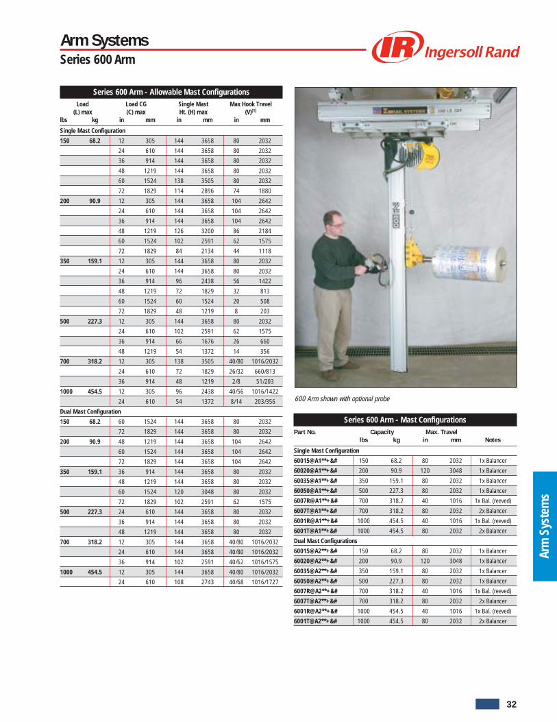
600 Arm shown with optional probe
Arm SystemsSeries 600 Arm
Series 600 Arm - Mast ConfigurationsPart No. Capacity Max. Travel
lbs kg in mm Notes
Single Mast Configuration
60015@A1**+&# 150 68.2 80 2032 1x Balancer
60020@A1**+&# 200 90.9 120 3048 1x Balancer
60035@A1**+&# 350 159.1 80 2032 1x Balancer
60050@A1**+&# 500 227.3 80 2032 1x Balancer
6007R@A1**+&# 700 318.2 40 1016 1x Bal. (reeved)
6007T@A1**+&# 700 318.2 80 2032 2x Balancer
6001R@A1**+&# 1000 454.5 40 1016 1x Bal. (reeved)
6001T@A1**+&# 1000 454.5 80 2032 2x Balancer
Dual Mast Configurations
60015@A2**+&# 150 68.2 80 2032 1x Balancer
60020@A2**+&# 200 90.9 120 3048 1x Balancer
60035@A2**+&# 350 159.1 80 2032 1x Balancer
60050@A2**+&# 500 227.3 80 2032 1x Balancer
6007R@A2**+&# 700 318.2 40 1016 1x Bal. (reeved)
6007T@A2**+&# 700 318.2 80 2032 2x Balancer
6001R@A2**+&# 1000 454.5 40 1016 1x Bal. (reeved)
6001T@A2**+&# 1000 454.5 80 2032 2x Balancer
Series 600 Arm - Allowable Mast ConfigurationsLoad Load CG Single Mast Max Hook Travel
(L) max (C) max Ht. (H) max (V)(1)
lbs kg in mm in mm in mm
Single Mast Configuration
150 68.2 12 305 144 3658 80 2032
24 610 144 3658 80 2032
36 914 144 3658 80 2032
48 1219 144 3658 80 2032
60 1524 138 3505 80 2032
72 1829 114 2896 74 1880
200 90.9 12 305 144 3658 104 2642
24 610 144 3658 104 2642
36 914 144 3658 104 2642
48 1219 126 3200 86 2184
60 1524 102 2591 62 1575
72 1829 84 2134 44 1118
350 159.1 12 305 144 3658 80 2032
24 610 144 3658 80 2032
36 914 96 2438 56 1422
48 1219 72 1829 32 813
60 1524 60 1524 20 508
72 1829 48 1219 8 203
500 227.3 12 305 144 3658 80 2032
24 610 102 2591 62 1575
36 914 66 1676 26 660
48 1219 54 1372 14 356
700 318.2 12 305 138 3505 40/80 1016/2032
24 610 72 1829 26/32 660/813
36 914 48 1219 2/8 51/203
1000 454.5 12 305 96 2438 40/56 1016/1422
24 610 54 1372 8/14 203/356
Dual Mast Configuration
150 68.2 60 1524 144 3658 80 2032
72 1829 144 3658 80 2032
200 90.9 48 1219 144 3658 104 2642
60 1524 144 3658 104 2642
72 1829 144 3658 104 2642
350 159.1 36 914 144 3658 80 2032
48 1219 144 3658 80 2032
60 1524 120 3048 80 2032
72 1829 102 2591 62 1575
500 227.3 24 610 144 3658 80 2032
36 914 144 3658 80 2032
48 1219 144 3658 80 2032
700 318.2 12 305 144 3658 40/80 1016/2032
24 610 144 3658 40/80 1016/2032
36 914 102 2591 40/62 1016/1575
1000 454.5 12 305 144 3658 40/80 1016/2032
24 610 108 2743 40/68 1016/1727
32
Untitled-1 5/8/06, 12:00 PM35

Arm
Sys
tem
s
Arm SystemsSeries 600 Arm
L
CS
H
(2" Min.)
Floor
Dh
C
Series 600 Arm - Mast ConfigurationsPart No. Arm Sub-Assy No. Balancer Part No.
Single Mast Configuration
60015@A1**+&# 54039649 BW015080000
60020@A1**+&# 54039664 BW020120S00
60035@A1**+&# 54039664 BW035080S00
60050@A1**+&# 54039664 BW050080S00
6007R@A1**+&# 54039664 BW070040S00
6007T@A1**+&# 54039680 BW070080S00
6001R@A1**+&# 54039664 BW100040S00
6001T@A1**+&# 54039680 BW100080S00
Dual Mast Configuration
60015@A2**+&# 54039656 BW015080000
60020@A2**+&# 54039672 BW020120S00
60035@A2**+&# 54039672 BW035080S00
60050@A2**+&# 54039672 BW050080S00
6007R@A2**+&# 54039672 BW070040S00
6007T@A2**+&# 54039698 BW070080S00
6001R@A2**+&# 54039672 BW100040S00
6001T@A2**+&# 54039698 BW100080S00
Controls (+)Controls Sub-Assembly No.
+ Description 1x Mast 2x Mast
Z ZA (Zim-Air) Control 54039847 54039854
Carriages (**)** Description Stack-up(1) (CS) Part No.
NT Carriage-Basic, no trolleys 40710
TR Carriage - T-Rail / I-Beam 5.46 40709
A2 Carriage - ZRA2 (reaction trolley) 5.97 30028-1
S2 Carriage - ZRS2 / ZRS3 5.97 30028-2
A1 Carriage - ZRA1 8.44 30028-3
E8 Carriage - ETA-8 (reaction trolley) 7.16 30028-4
K2 Carriage - KBK2 5.97 30028-5
Note:Lightweight ALMAG casting. Carriage weighs 60.0 lbs (27.3 kg)(1) Dimension is from the rail running surface to the base of the pivot. Changes with brake
option.
Masts (#)# Description Part No.
A ZRA2 Mast, 4' [1.22 m] Long 30000-040-2
B ZRA2 Mast, 4' 6" [1.37 m] Long 30000-045-2
C ZRA2 Mast, 5' [1.52 m] Long 30000-050-2
D ZRA2 Mast, 5' 6" [1.68 m] Long 30000-055-2
E ZRA2 Mast, 6' [1.83 m] Long 30000-060-2
F ZRA2 Mast, 6' 6" [1.98 m] Long 30000-065-2
G ZRA2 Mast, 7' [2.13 m] Long 30000-070-2
H ZRA2 Mast, 7' 6" [2.29 m] Long 30000-075-2
J ZRA2 Mast, 8' [2.44 m] Long 30000-080-2
K ZRA2 Mast, 8' 6" [2.59 m] Long 30000-085-2
M ZRA2 Mast, 9' [2.74 m] Long 30000-090-2
N ZRA2 Mast, 9' 6" [2.90 m] Long 30000-095-2
P ZRA2 Mast, 10' [3.05 m] Long 30000-100-2
Q ZRA2 Mast, 10' 6" [3.20 m] Long 30000-105-2
R ZRA2 Mast, 11' [3.35 m] Long 30000-110-2
S ZRA2 Mast, 11' 6" [3.51 m] Long 30000-115-2
T ZRA2 Mast, 12' [3.66 m] Long 30000-120-2
Brake Options (&)& Description Part No.
0 No brake -
P Pin-lock Brake (hard stops every 45 degrees) 54039722
B Bumper Friction Brake 54039730
C Caliper Brake 54040977
Vertical Travel of Balancer (Q) VS. Mast Height (H) - 32 in (812mm)Balancer Capacity Vertical Travel (Q)lbs kg in mm Notes
150 68.2 80 2032 1 x Balancer
200 90.9 120 3048 1 x Balancer
350 159.1 80 2032 1 x Balancer
500 227.3 80 2032 1 x Balancer
700(1) 318.2 40 1016 1 x Balancer (reeved)
700(2) 318.2 80 2032 2 x Balancer
1000(1) 454.5 40 1016 1 x Balancer (reeved)
1000(2) 454.5 80 2032 2 x Balancer
Notes:(1) = 1 Balancers Reeved(2) = 2 Balancers Tandem
33
Untitled-1 5/8/06, 12:00 PM36

Arm
Sys
tem
s
Example: 60015IA1A2ZPG 600 15 I A 1 A2 Z P G
Style
600
Capacity - Vertical Travel
15 = 150 lbs (68.2 kg) - 80 in. (2032 mm)20 = 200 lbs (90.9 kg) - 120 in. (3048 mm)35 = 350 lbs (159.1 kg) - 80 in. (2032 mm)50 = 500 lbs (227.3 kg) - 80 in. (2032 mm)7R = 700 lbs (318.2 kg) - 40 in. (1016 mm)7T = 700 lbs (318.2 kg) - 80 in. (2032 mm)1R = 1000 lbs (454.5 kg) - 40 in. (1016 mm)1T = 1000 lbs (454.5 kg) - 80 in. (2032 mm)
Intelift Options (@)
S = Standard BalancerI = Intelift Balancer (Consult factory)
Arm
Single or Dual Mast
1 = Single Mast2 = Dual Mast
Carriage Options (**)
A1 = ZRA1A2 = ZRA2S2 = ZRS2S3 = ZRS3TR = T-RailE8 = ETA-8K2 = KBK2Note: All Ingersoll-Rand 600 Arms use a Low Profile Carriage Assembly
Controls (+)
Z = ZA (Zim-Air) Control (Includes dummy handle)
Brake Options (&)
0 = No brakeP = Pin-lock Brake (hard stops every 45 degrees)B = Bumper Friction Brake (soft stop at any point on 360 degree rotation)C = Caliper Brake
Mast Length (#)
A = 4 ft (1.22 m) G = 7 ft (2.13 m) P = 10 ft (3.05 m)B = 4 ft 6 in. (1.37 m) H = 7 ft 6 in. (2.29 m) Q = 10 ft 6 in. (3.20 m)C = 5 ft (1.52 m) J = 8 ft (2.44 m) R = 11 ft (3.35 m)D = 5 ft 6 in. (1.68 m) K = 8 ft 6 in. (2.59 m) S = 11 ft 6 in. (3.51 m)E = 6 ft (1.83 m) M = 9 ft (2.59 m) T = 12 ft (3.66 m)F = 6 ft 6 in. (1.98 m) N = 9 ft 6 in. (2.90 m)
How to OrderSeries 600 Arms
34
Untitled-1 5/8/06, 12:00 PM37

Hand
ling
Devi
ces
Lifting and Positioning Systems
Ingersoll-Rand has over 40 years of experience in custom designed material handling systems. With many innovations in the design ofhandling devices to our credit, we offer a complete range of end effectors from the simplest to the most complex device. In every respect IRZimmerman is an essential part of a more productive ergonomic work place, empowering individuals to work more comfortably andeffectively.
Handling Devices
Ingersoll-Rand provided material handling solutions to Thermo KIng®in handling the back panel for a refrigeration unit. The handlingdevice includes a Power Tilt feature.
SafetyMost Ingersoll-Rand End Effectors come equipped with aSafety Interlock system that will not allow the operator toaccidently disengage the part during transfer.
Safety Cost SavingsFlexibility Ergonomics Productivity
Call 1-800-347-7047
for distributors in your area
35
Untitled-1 5/8/06, 12:00 PM38

Hand
ling
Devi
ces
Handling Devices
Ingersoll-Rand Material Handling Products in a cleanroom high tech environment application.
The spool handling device shown here used by a major pharmaceutical productsmanufacturer, has Dual Controls. The spools are stacked 3-high in a box and theDual Controls enable the operator to pick up spools without bending.
Safety Cost SavingsFlexibility Ergonomics Productivity
FlexibilityThrough a variety of pneumatic packageseach system is matched to a controlpackage that is tailored to the lifting andpositioning task.
36
Untitled-1 5/8/06, 12:00 PM39

Hand
ling
Devi
ces
Handling Devices
Air clamp handling device for engine rollover
Vacum end effector integrated with 4 Ingersoll-Rand D-Series nut runners showninstalling a lift gate assembly.
Tire handling device with 90 degreemanual rotate.
Clamp handling device with 90 degree power tiltshown handling an alternator.
Safety Cost SavingsFlexibility Ergonomics Productivity
ErgonomicsEnd Effectors can be designed with manual and/orpowered tilt and rotation packages, which allow theoperator to orient the part to the proper positionwith minimal effort.
Call 1-800-347-7047
for distributors in your area
37
Untitled-1 5/8/06, 12:01 PM40

Hand
ling
Devi
ces
Ingersoll-Rand pioneered the development of pneumatic powered lifting and balancing equipment, making us a world leader in themanufacture of ergonomic, in-process, manual assist, pick and place systems. With over 40 years of experience in providing ergonomiclifting systems for the converting (Paper, Film, & Foil) and packaging industries, we have a solution to fit your needs.We specialize in providing turn-key solutions utilizing our complete line of standard and custom products to create a combination that meetsyour needs.
Rotary Action Handler
• 90 degree manual rotation of rolls.• Cast aluminum construction for light weight.• Rubber band (non-destructive) and pin style noses engage the I.D. of the core.• Optional side clamp to prevent telescoping of rolls.• Safety interlock to prevent operator from releasing the load during transfer.
Roll Handling Solutions
Power-Tilt Roll Handling Device
• Powered 90 degree rotation.• Multiple sizes, up to 500 lb rolls.• Rubber band (non-destructive) and pin style noses engage the I.D. of the core.• Optional shifting center of gravity.• Optional side clamp to prevent telescoping of rolls.• Safety interlock to prevent operator from releasing the load during transfer.
Optional partpresent sensor
Shown rotated 90°
Rotationlockrelease
Interchangeablepart gripper
Moldedrubberhandle
Clampindicator
Release pull pin for inter-changeablegripper
Airlines
Interlock
ZIM aircontrol
Clamp-unclampswitch
Rotates and locks 90˚ right and leftWide variety of interchangeable part grippersavailable
Nondestructive step noseNondestructive nose
75 lb copper coil used in refrigerationcontainer units with 90 degree rotatefrom Thermo King®
38
Untitled-1 5/8/06, 12:01 PM41
Hand
ling
Devi
ces
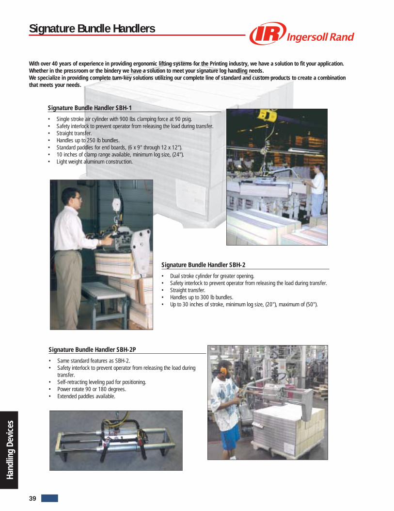
With over 40 years of experience in providing ergonomic lifting systems for the Printing industry, we have a solution to fit your application.Whether in the pressroom or the bindery we have a solution to meet your signature log handling needs.We specialize in providing complete turn-key solutions utilizing our complete line of standard and custom products to create a combinationthat meets your needs.
Signature Bundle Handler SBH-1
• Single stroke air cylinder with 900 lbs clamping force at 90 psig.• Safety interlock to prevent operator from releasing the load during transfer.• Straight transfer.• Handles up to 250 lb bundles.• Standard paddles for end boards, (6 x 9" through 12 x 12").• 10 inches of clamp range available, minimum log size, (24").• Light weight aluminum construction.
Signature Bundle Handlers
Signature Bundle Handler SBH-2
• Dual stroke cylinder for greater opening.• Safety interlock to prevent operator from releasing the load during transfer.• Straight transfer.• Handles up to 300 lb bundles.• Up to 30 inches of stroke, minimum log size, (20"), maximum of (50").
Signature Bundle Handler SBH-2P
• Same standard features as SBH-2.• Safety interlock to prevent operator from releasing the load during
transfer.• Self-retracting leveling pad for positioning.• Power rotate 90 or 180 degrees.• Extended paddles available.
39
Untitled-1 5/8/06, 12:01 PM42

Torq
ue A
rms
Features/Benefits
• Air Bias Support System Air Adjustment bymini-regulator with air cylinder, for properpositioning of different size tools. Eliminatesthe clumsy spring adjustment of competitivemodels. Tool positioning is effortless.
• Parallel Arm Torque Absorber Absorbstorque reaction up to 120 in. lbs. Increasestorque repeatability through shift changes byreducing operator influence on fastener.Keeps tools off the floor.
• Steel & Aluminum Construction Anodizedfinish Lightweight Heavy duty for highvolume production Corrosion resistant.
• Auto-Orientation System Tool fixture isdesigned to allow constant perpendicularorientation of the tool, which ensures properfastener alignment.
Accessories
• 48732-1 Bench clamp for mounting arm inplace
• C10-02-000 Filter/Lubricator (1/4”)• R00-02-G00 Regulator (1/4”)• IR49541 Swivel Mount Kit Grip and Angle
Tools (adapts pistol to the workstation)
Dimensions
IRBP3-N30
IRBP3-E30
Parallel Torque Arms
39" (991 mm)*
27" (686 mm)*
16" (406 mm)*
32.5" (826 mm)
* Measurements taken with base at extended height.** Adjustable between 15" and 22".
15" (381 mm)
15"-22"** (381-559 mm)
Base
8.8" (223 mm)
Min.Radius
Max.Radius
30" Arm9.5" (241 mm) min.34" (864 mm) max.
48732-1 IR49541
Parallel Torque ArmsModel no. Length (in.) Tool use Torque absorber
IRBP3-N30 30 Air Yes
IRBP3-E30 30 Electric Yes
Filter/Regulattor (1/4 in.)B18-02-FKG0-28
Lubricator (1/4 in.)L18-02-LK00-28
40
Untitled-1 5/8/06, 12:01 PM43

Torq
ue A
rms
Features/Benefits
• Steel Construction: E-Coat Lightweight butdurable for continuous duty.Corrosion Resistant.
• Flexible: Your choice of 30” or 24” lengthsfor electric or air tools.
• Balancer Hanger: All arms are equippedwith a roller mounted balancer hanger forsmooth motion of the tool.
• Electric Cord Clamp Kit: Standard withappropriate models.
Options
• Single Arm Torque Absorber: Telescopingtorque arm improves flexibility. Eliminatestorque reaction from the tool.
Accessories
• Balancers – Choice of balancers7/8 to 2-1/4 lbs Bld 12 to 4 lbs = Bld 24 to 6 lbs = Bld 3
• 48732-1 Bench clamp for mounting arm inplace
• C10-02-000 Filter/Lubricator (1/4”)• R00-02-G00 Regulator (1/4”)
Parallel Torque ArmsModel no. Length (in.) Tool use Torque absorber
IRBS2-N0 24 Air No
IRBS2-N24 24 Air Yes
IRBS2-E0 24 Electric No
IRBS2-N24 24 Electric Yes
IRBS3-N0 30 Air No
IRBS3-N30 30 Air Yes
IRBS3-E0 30 Electric No
IRBS3-E30 30 Electric Yes
Max.Radius
Min.Radius
760 mm (30 in) Arm:305 mm (12 in) Minimum825 mm (32.5 in) Maximum
610 mm (24 in) Arm:208 mm (8.5 in) Minimum625 mm (25.5 in) Maximum
1"
2"
82 mm(3.25 in)
45 mm(1.75 in)
Dimensions
Beam Clamp
1067 mm(42 in)
76 mm sq.(3 in)
57 mm sq.(2.25 in)centre distancefor 6.4 mm(1/4") Bolt
762 mm(30 in) Arm
610 mm(24 in) Arm
TOP ROLLERASSEMBLY
Electric Tool Clamp
Single Arm Workstations
48732-1 IRAX Balancer
IRBS3-N30 (Hose, FRL and balancer not included)
IRBS3-E0
Filter/Regulattor (1/4 in.)B18-02-FKG0-28
Lubricator (1/4 in.)L18-02-LK00-28
41
Untitled-1 5/8/06, 12:01 PM44

Torq
ue A
rms
EZ tool arm features:
• Covers a 610 x 762 mm (24 x 30 inch) horizontal rectangular workenvelope.
• Two piece arm with overall length adjustable from 864 to 1067 mm(34 to 42 inches).
• Anodized aluminum construction.• Mounting plates attach vertically or horizontally.• First portion of the arm consists of two adjustable sections connected
to the mounting plate by a 360 degree pivot.• Second, outer portion of the arm is a dual parallel arm design that
allows for 500 mm (20 inches) of vertical travel, and is connected tothe first portion by a 360 degree pivot.
EZ Tool Articulating Arm
EZ Tool Arm in an assembly process
Additional features:
• Each pivot contains roller bearings for smooth operation and anadjustable pivot spring to return the arm to a “home” position.
• Capacity is 13.6 kg (30 lb) at 7 bar (100 psi).• Pneumatics control system consists of a single precision pneumatic
regulator to allow balance of the end of the arm Maximum torquereaction is 80 Nm (60 ft/lb).
• Fixed tool holder to handle tool diameter from 13 to63.5 mm (.50 to 2.5 inches) is adjustable for vertical orhorizontal tool orientation.
42
Untitled-1 5/8/06, 12:01 PM45

Torq
ue A
rms
EZ Tool ArmPart no. Description
EZTA080500 Light weight torque arm with tool holder
43146000 Light weight articulating arm without tool holder
EZ tool arm model number EZTA080500 illustrated
Tool HoldersPart no. Description
54033162 Bi-Directional tilt / Push to start tool
54033196 Single-Directional tilt tool holder
EZ Tool Articulating Arm Specifications
247 mm(9.74")
272 mm(10.70")
787.4 mm(31")
367 mm (14.45”) min. adj.
558.8 mm (22.00”) max. adj.
1066.8 mm (42.00”) full extend
Low frictioncylinder
Lightweight anodizedaluminum construction
360 degree rotation
360 degreerotation
Adjustable lengthh
Adjustablemounting bar
Easy vertical tohorizontal tooladjustment
Mounting plateseasilyconfigure tomount on tabletops,walls, ceilings,columns, etc.
Fasteners for 10 mmnot supplied (Typ.)
Horizontal (tabletop or floormounting option
Vertical (ceiling or wall) mounting option(rotate 90˚ for wall mount)˚
38.1 mm (1.50")
43
Untitled-1 5/8/06, 12:01 PM46

Torq
ue A
rms
Just as the name indicates, the new Ingersoll-Rand E-Z Torque® has taken the struggle out of using hand-held torque tools.
The lightweight E-Z Torque has been coupled with our 50 pound Balancer to provide the most innovative power tool assist system availabletoday. Ease of operation eliminates operator fatigue problems, fights carpal tunnel syndrome and brings added safety to the workstation.E-Z Torque has been engineered to absorb the pounding reaction of air-powered or electric-driven torque tools. Constructed of castaluminum and steel with ball bearing rollers and a 48 inch (1219.2 mm) vertical travel, the E-Z Torque eliminates spring pull back andmaintains tool position with no problem.
Features:
• Lightweight torque tool assist• Ease of operation• Reduces operator fatigue• Aluminum and steel construction• Adjustable to fit any tool
The tool holder is adjustable to fitany tool within the 2–50 lb (.9–22 kg)capacity of our reliable Balance Air unit. The E-Z Torque canhandle up to 100 ft lbs torque, day after day for years to come.
E-Z Torque shown with optional tool
48”(1219.2 mm)Reactionbar std.
Ballbearingrollers
Adjustmentbracket
Highstrengthcastaluminum
Cableanchor
Trolleyor fixedmounting
Toolholder
Cableanchor
Toolholder
1/8” (3 mm)Aircraftcable
50 lb(22 kg)Balancer
E-Z Torque
E-Z TorquePart no. complete Application
EZTQ5060 EZ Torque Tool Balancer
Suspension Kits
16520 ZRA1 rail
16525 ZRA2 rail
16530 ZRS2/3 rail
44
Untitled-1 5/8/06, 12:01 PM47

Torq
ue A
rms
IN OUT
IN OUT
IN OUT
Ergonomic Torque Reaction ProductsTorque Tube
Torque Tube Features• Available in 3 torque capacities: 100 Nm, 250 Nm, and 500 Nm• Modular worldwide metric design• Super linear bearings for effortless vertical travel and maintenance free
operation• 60 lb, 60 lb and 400 lb capacities• 4 Delrin wheels for torque reaction and side loading in all four directions• Adjustable lengths (every 2 inches/ 50.8 mm) to eliminate the need for
extension tubes• All bolt on assemblies (Tool Holders and Suspension)• Lightweight construction
Ingersoll-Rand is proud to introduce the world’s first IRZ Series of Best-In-Class Ergonomic Torque Tube Products. The new IRZ series ofproducts relieve the operator of tool weight and torque reaction, resulting in increased work place productivity. These products aredesigned to prevent the long-term damaging effects of torque reaction on the human body, resulting in lower workers compensationand health care costs.
The new IRZ Series Torque Tubes allow tools to be lifted, lowered, moved and brought into optimum working position with minimal force required by the operator.Whether the products are used alone or integrated into a larger “turnkey” system, the smooth and effortless vertical motion will be the perfect solution for assemblyapplications. The availability of various sizes and the modularity of design provides System Integrators and Tool Builders the flexibility they need, to offer assemblysolutions to customers.
Torque TubePart Torque Capacity Lift Capacity Weight TravelNo. Description ft-lbs Nm lbs @ 100 psi lbs @ 7 kg/cm2 lbs kg in. mm
54044227 IRZ-TT-100 74 100 60 27 40 18 20 50854041819 IRZ-TT-250 184 250 60 27 50 23 24 610540444171,2 IRZ-TT-500 368 500 400 182 75 75 36 914
(1) Carriage mount option only.(2) Custom tool holder required - contact factory.
Air cylinder andregulator are includedin these part numbers.
Fixed (2 axis)Horizontal/vertical tool holder
360 degree (3 axis)swivel tool holder
D
.75 to adjust
D
.75 to 2.5adjustable
2.5able
Tool Holder Features• Tool holder clamp is 316 stainless steel construction designed to minimize
tool damage• Accepts tools of 19 mm to 63 mm/.75 to 2.5 in. diameter• Switches easily from horizontal to vertical orientation360 degree tool holder features:• Generous 66.8 mm/2.63 in. opening insures that tool head does not have to
be removed for quick changes• Bronze bushing provides easy rotation and durability• Rotates freely through 360 degrees or locks at 45 degree increments with
indexing plungerFixed tool holder• Fixed tool holder accepts tools of 13 to 63 mm (.50 to 2.5 inch) diameter• Tool holder easily changes from horizontal to vertical• Custom tool holders available
Tool Holders for IRZ-TT-100 and IRZ-TT-250Part Description “D” Dimension WeightNo. in. mm lbs kg
52000 Fixed (2 axis) horiz./vertical 4.82 122 2.30 .9052100 360 degree (3 axis) swivel 5.38 136.7 5.00 2.27
Note: IRZ-TT-500 requires custom tool holder
Part No.54044417
Part No.54041819
Part No.54044227
Selflockinghardware
GoldAnodizedAluminum
Lowfrictioncylinder
Highflowregulator
Universal 1.25” square mount
9” Dia. carriage mount
Travel36”
Zinc platedfinish
Lengthadjustablefrom 40” to60” in 2”increments
Lengthadjustablefrom 48” to72” in 2”increments
11/32 Drill thruTyp. (4) holes
11/32 Drill thruTyp. (4) holes
45
Untitled-1 5/8/06, 12:01 PM48
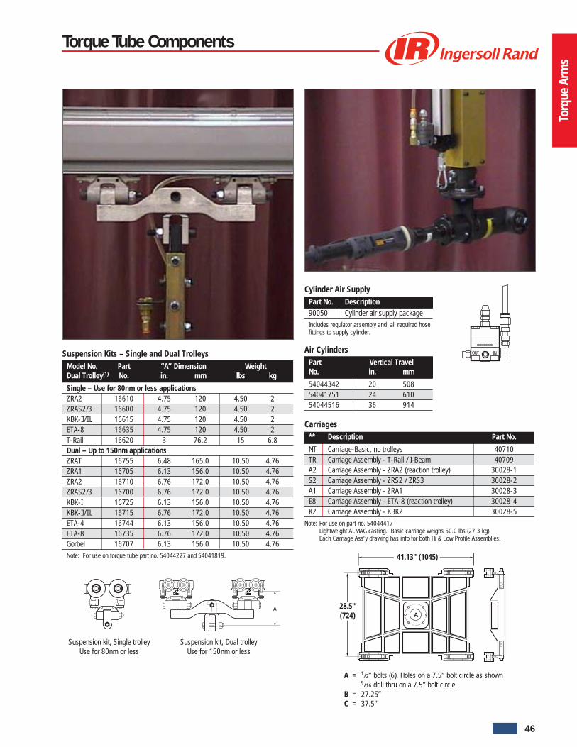
Torq
ue A
rms
Torque Tube Components
Suspension kit, Dual trolleyUse for 150nm or less
A
Suspension kit, Single trolleyUse for 80nm or less
OUT INAir CylindersPart Vertical TravelNo. in. mm
54044342 20 50854041751 24 61054044516 36 914
Carriages** Description Part No.
NT Carriage-Basic, no trolleys 40710TR Carriage Assembly - T-Rail / I-Beam 40709A2 Carriage Assembly - ZRA2 (reaction trolley) 30028-1S2 Carriage Assembly - ZRS2 / ZRS3 30028-2A1 Carriage Assembly - ZRA1 30028-3E8 Carriage Assembly - ETA-8 (reaction trolley) 30028-4K2 Carriage Assembly - KBK2 30028-5
Note: For use on part no. 54044417Lightweight ALMAG casting. Basic carriage weighs 60.0 lbs (27.3 kg)Each Carriage Ass’y drawing has info for both Hi & Low Profile Assemblies.
A = 1/2” bolts (6), Holes on a 7.5” bolt circle as shown9/16 drill thru on a 7.5” bolt circle.
B = 27.25”C = 37.5”
41.13" (1045)
A28.5"(724)
Cylinder Air SupplyPart No. Description90050 Cylinder air supply package
Includes regulator assembly and all required hosefittings to supply cylinder.
Suspension Kits – Single and Dual TrolleysModel No. Part “A” Dimension WeightDual Trolley(1) No. in. mm lbs kg
Single – Use for 80nm or less applicationsZRA2 16610 4.75 120 4.50 2ZRAS2/3 16600 4.75 120 4.50 2KBK-II/IIL 16615 4.75 120 4.50 2ETA-8 16635 4.75 120 4.50 2T-Rail 16620 3 76.2 15 6.8Dual – Up to 150nm applicationsZRAT 16755 6.48 165.0 10.50 4.76ZRA1 16705 6.13 156.0 10.50 4.76ZRA2 16710 6.76 172.0 10.50 4.76ZRAS2/3 16700 6.76 172.0 10.50 4.76KBK-I 16725 6.13 156.0 10.50 4.76KBK-II/IIL 16715 6.76 172.0 10.50 4.76ETA-4 16744 6.13 156.0 10.50 4.76ETA-8 16735 6.76 172.0 10.50 4.76Gorbel 16707 6.13 156.0 10.50 4.76
Note: For use on torque tube part no. 54044227 and 54041819.
46
Untitled-1 5/8/06, 12:01 PM49

Torq
ue A
rms
Heavy duty tool arm features:
• Lightweight, anodized aluminum construction.• Modular metric design.• 150 nm (110 ft/lb) of torque reaction.• 50 kg/110 lb of capacity at 2 m/6.5 ft with 7 bar/100 psi.• 500 mm/20 inches of vertical travel.• Externally mounted sealed and lubricated roller bearings.• Pneumatics control system consists of a single precision
pneumatic regulator to allow balance at the end of the arm.• Numerous mounting configurations.
Options:
• Multiple tool holders and extension tubes (see torque tube component specifications for tool holders and extension tubes available).• Optional pivot provides up to 220 degrees of rotation and includes adjustable stops to limit rotation.• Optional locking pivot brake renders arm rigid to absorb torque.
Heavy Duty Tool Arm
110˚ 110˚
Top view of medium duty tool armshowing 220 degree rotation
Optional 360 degree (3 axis)swivel tool holder
47
Untitled-1 5/8/06, 12:02 PM50

Torq
ue A
rms
Heavy Duty Tool Arm Specifications
AdapterPivot
120 mm
(4.7”)
Extension120, 500 and
1000 mm
(4.7, 19.7and 39.4”)
Parallel link arm690 mm (27.2”) max.
1810 mm (71.26”) max.
Pivot120 mm
(4.7”)
330.2 x 330.2 mm(13 x 13")
Pivot120 mm
(4.7”)
30 mm (1.2”)
10 mm (Typ.)
241 mm
(9.5”)Adapter
Pivot120 mm
(4.7”)
101.6 mm
(4 x 4”)
101.6 mm
(4 x 4”)
54033261
Mounting Plate
(Back Side)
54033279
Mounting Plate
(Front Side)
Heavy Duty Tool Arm 1
Part no. Description
58252479 Parallel link section (508 mm/20 inches of vertical travel, 50 kg/110 lb cap.)
58252487 Pivot
58252495 Pivot brake option (150 nm/100 ft lb of torque reaction)
58252735 Rigid arm extension (0.5 m)
58252750 Rigid arm extension (1.0 m)
58252503 90 degree adapter bracket to engage tool holder
58253402 Column assembly
52100 360 degree (3 axis) swivel tool holder
52000 Fixed (2 axis) horizontal/vertical tool holder
54033261 Mounting plate (Back side)
54033279 Mounting plate (Front side)
54036009 Column
Note:(1) Call Customer Service for control options.
Note:Standard column is 10 ft high. Please specify cut down lengths whileordering, if different height is desired.
Control packages, pivot brake option and cylinder control packagesavailable on request.
Max weight capacity is 100 lbs (45.36 kg)
Max torque reaction is 150 Nm (110 ft lbs)
48
Please consult factory for additional models and configurations.
Untitled-1 5/8/06, 12:02 PM51
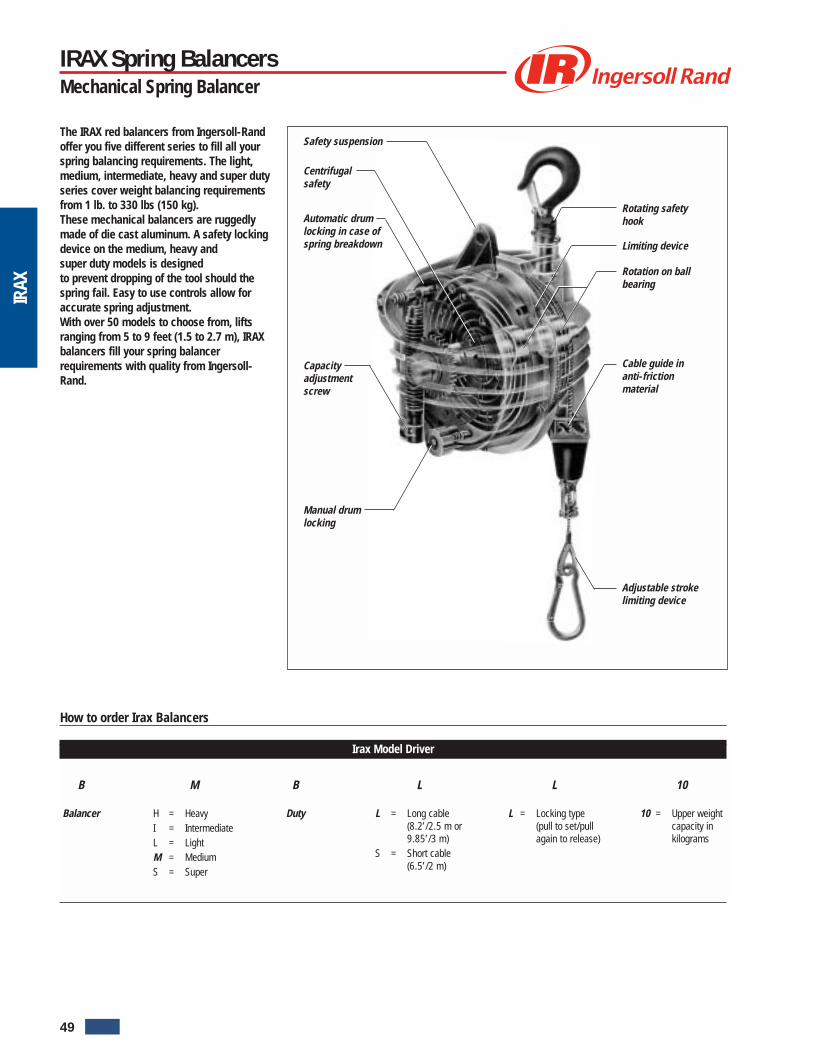
IRAX
The IRAX red balancers from Ingersoll-Randoffer you five different series to fill all yourspring balancing requirements. The light,medium, intermediate, heavy and super dutyseries cover weight balancing requirementsfrom 1 lb. to 330 lbs (150 kg).These mechanical balancers are ruggedlymade of die cast aluminum. A safety lockingdevice on the medium, heavy andsuper duty models is designedto prevent dropping of the tool should thespring fail. Easy to use controls allow foraccurate spring adjustment.With over 50 models to choose from, liftsranging from 5 to 9 feet (1.5 to 2.7 m), IRAXbalancers fill your spring balancerrequirements with quality from Ingersoll-Rand.
Safety suspension
Centrifugalsafety
Automatic drumlocking in case ofspring breakdown
Capacityadjustmentscrew
Manual drumlocking
Rotating safetyhook
Limiting device
Rotation on ballbearing
Cable guide inanti-frictionmaterial
Adjustable strokelimiting device
How to order Irax Balancers
Irax Model Driver
B
Balancer
B
Duty
L
L = Long cable(8.2’/2.5 m or9.85’/3 m)
S = Short cable(6.5’/2 m)
10
10 = Upper weightcapacity inkilograms
M
H = HeavyI = IntermediateL = LightM = MediumS = Super
L
L = Locking type(pull to set/pullagain to release)
IRAX Spring BalancersMechanical Spring Balancer
49
Untitled-1 5/8/06, 12:02 PM52
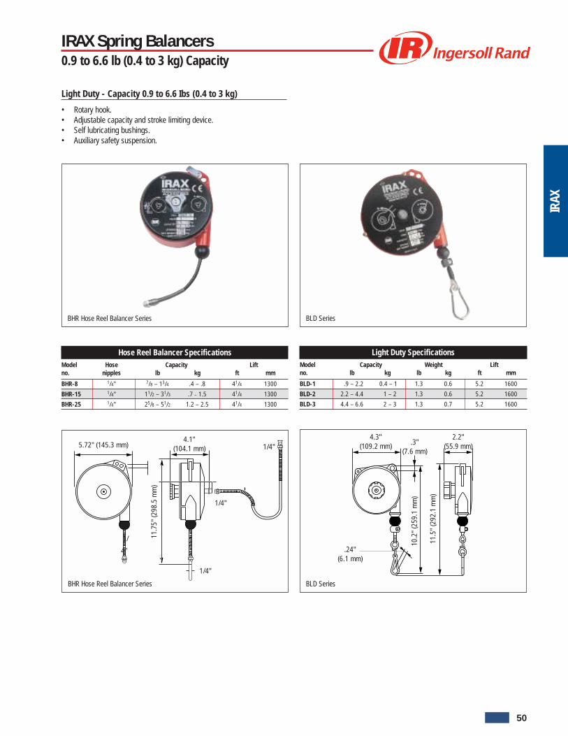
IRAX
1/
4"
1/4"
5.72" (145.3 mm)
11.7
5" (2
98.5
mm
)
BHR Hose Reel Balancer Series
1/4"
1/4"4.1"
(104.1 mm)
BLD Series
4.3"(109.2 mm)
11.5
" (2
92.1
mm
)
10.2
" (2
59.1
mm
)
2.2"(55.9 mm).3"
(7.6 mm)
.24"(6.1 mm)
Light Duty - Capacity 0.9 to 6.6 Ibs (0.4 to 3 kg)
• Rotary hook.• Adjustable capacity and stroke limiting device.• Self lubricating bushings.• Auxiliary safety suspension.
BHR Hose Reel Balancer Series BLD Series
IRAX Spring Balancers0.9 to 6.6 lb (0.4 to 3 kg) Capacity
Hose Reel Balancer SpecificationsModel Hose Capacity Liftno. nipples lb kg ft mm
BHR-8 1/4" 7/8 – 13/4 .4 – .8 41/4 1300
BHR-15 1/4" 11/2 – 31/3 .7 – 1.5 41/4 1300
BHR-25 1/4" 25/8 – 51/2 1.2 – 2.5 41/4 1300
Light Duty SpecificationsModel Capacity Weight Liftno. lb kg lb kg ft mm
BLD-1 .9 – 2.2 0.4 – 1 1.3 0.6 5.2 1600
BLD-2 2.2 – 4.4 1 – 2 1.3 0.6 5.2 1600
BLD-3 4.4 – 6.6 2 – 3 1.3 0.7 5.2 1600
50
Untitled-1 5/8/06, 12:02 PM53

IRAX
BMDS Series BMDL Series
5.9"(147.5 mm)
11.1
" (2
91.9
mm
)
10.8
" (2
54.3
mm
)
3.4"(86.4 mm)
.3"(7.6 mm)
.3"(7.6 mm)
13.6
" (3
45.4
mm
)
13"
(330
.2 m
m)
3.4"(86.4 mm)
7.1"(180.3 mm)
.4"(10.2mm)
.3"(7.6 mm)
Medium Duty - Capacity 4.4 to 26.5 Ibs (2 to 12 kg)
• Safety device prevents dropping of load due to spring breakage• Anti-friction cable guide.• Adjustable stroke limiting device
BMDS Series BMDL Series
IRAX Spring Balancers2.2 to 26.5 lb (1 to 12 kg) Capacity
Medium Duty - Capacity 2.2 to 26.5 Ibs (1 to 12 kg)
• Safety device prevents dropping of load due to spring breakage(except BMDS-2).
• Anti-friction cable guide.• Adjustable stroke limiting device
Medium Duty SpecificationsModel Capacity Weight Liftno. lb kg lb kg ft mm
BMDS-2 2.2 – 5.5 1 – 2.5 4.4 2.0 6.5 2000
BMDS-4 4.4 – 8.8 2 – 4 4.4 2.0 6.5 2000
BMDS-6 8.8 – 13.2 4 – 6 5.1 2.3 6.5 2000
BMDS-8 13.2 – 17.6 6 – 8 5.5 2.5 6.5 2000
Medium Duty long Lift SpecificationsModel Capacity Weight Liftno. lb kg lb kg ft mm
BMDL-4 4.4 – 8.8 2 – 4 6.4 2.9 8.2 2500
BMDL-6 8.8 – 13.2 4 – 6 7.1 3.2 8.2 2500
BMDL-8 13.2 – 17.6 6 – 8 7.7 3.5 8.2 2500
BMDL-10 17.6 – 22.0 8 – 10 8.2 3.7 8.2 2500
BMDL-12 22.0 – 26.5 10 – 12 8.8 4.0 8.2 2500
51
Untitled-1 5/8/06, 12:02 PM54

IRAX
9.5"(241.3 mm)
22.8
" (5
79.1
mm
)
5.9"(149.9 mm)
24.4
" (6
19.8
mm
)
.3" (7.6 mm)
Locking type balancer with long lift
• Pull to set—pull again to release
BIDS Series
1" (25.4 mm)
.5" (12.7 mm)
BMDLL Series BIDS Series
IRAX Spring Balancers4.4 to 55 lb (2 to 25 kg) Capacity
Intermediate Duty - 22 to 55 Ibs (10 to 25 kg)
• Safety device prevents load dropping due to spring breakage.• Adjustable stroke limiting device• Upper rotary suspension• Safety hook• Anti-friction cable guide• Auxiliary safety suspension• Auxiliary safety suspension
.4" (10.2 mm)
7.1" (180.3 mm)
13.6
" (3
45.4
mm
)
BMDLL Series
3.4"(86.4 mm)
13"
(330
.2 m
m)
Locking Type with Long Lift SpecificationsModel Capacity Weight Liftno. lb kg lb kg ft mm
BMDLL-4 4.4 – 8.8 2 – 4 6.6 3.0 8.2 2500
BMDLL-6 8.8 – 13.2 4 – 6 7.3 3.3 8.2 2500
BMDLL-8 13.2 – 17.6 6 – 8 7.9 3.6 8.2 2500
BMDLL-10 17.6 – 22.0 8 – 10 8.4 3.8 8.2 2500
Intermediate Duty SpecificationsModel Capacity Weight Liftno. lb kg lb kg ft mm
BIDS-15 22 – 33 10 – 15 16.5 7.5 6.5 2000
BIDS-20 33 – 44 15 – 20 17.0 7.7 6.5 2000
BIDS-25 44 – 55 20 – 25 17.2 7.8 6.5 2000
52
Untitled-1 5/8/06, 12:02 PM55

IRAX
BHD Series
24"
(609
.6 m
m)
22.1
" (5
61.3
mm
)
8.7" (221 mm)9.8" (248.9 mm)
.6" (15.2 mm)
.7" (17.8 mm)
.9" (22.9 mm)
1"(25.4 mm)
Heavy Duty - Capacity 22 to 143 Ibs (10 to 65 kg)
• Safety device prevents load dropping due to spring breakage.• Upper suspension with rotary safety hook.• Precision guided cable winding prevents jamming.• Antl-friction cable guide.• Manual locking device for instant clamping or release.• Worm screw capacity adjustment.• Spring drum assembly.• Optional floor controlled locking device available (BIL-7343).
BIL-7343
BHD Series
IRAX Spring Balancers22 to 143 lb (10 to 65 kg) Capacity
Heavy Duty SpecificationsModel Capacity Weight Liftno. lb kg lb kg ft mm
BHD-15 22 – 33 10 – 15 22.7 10.3 6.5 2000
BHD-20 33 – 44 15 – 20 23.4 10.6 6.5 2000
BHD-25 44 – 55 20 – 25 24.7 11.2 6.5 2000
BHD-30 55 – 66 25 – 30 25.4 11.5 6.5 2000
BHD-35 66 – 77 30 – 35 26.0 11.8 6.5 2000
BHD-45 77 – 99 35 – 45 27.3 12.4 6.5 2000
BHD-55 99 – 121 45 – 55 27.6 12.5 6.5 2000
BHD-65 121 – 143 55 – 65 30.0 13.6 6.5 2000
53
Untitled-1 5/8/06, 12:02 PM56

IRAX
Super Duty - Capacity 33 to 363 Ibs (15 to 165 kg)
• Safety device prevents load dropping due to spring breakage• Manual locking device for instant clamping or release• Anti-friction cable guide• Cable replacement without balancer disassembly• Optional floor controlled locking devide available (BIL-7343)• Precision guided cable winding prevents jamming• Alignable rotating upper hook• Worm screw capacity adjustment• Cable visible for inspection• Other sizes available on request
.7" (17.8 mm)
12" (304.8 mm)
27.6
" (7
01 m
m)
BSD-20 – 60/BSDL-20 – 35 Series
24"
(609
.6 m
m)
8.7" (221 mm)
1.1"(27.9 mm)
.6"(15.2 mm)
.9" (22.7 mm)
1"(25.4 mm)
BSD-20 – 60/BSDL-20 – 35 Series
IRAX Spring Balancers33 to 132 lb (15 to 60 kg) Capacity
Super Duty SpecificationsModel Capacity Weight Liftno. lb kg lb kg ft mm
BSD-20 33 – 44 15-20 41.9 19 8.2 2500
BSD-30 44 – 66 20-30 43.7 19.8 8.2 2500
BSD-40 66 – 88 30 – 40 45.9 20.8 8.2 2500
BSD-50 88 – 110 40 – 50 52.7 23.9 8.2 2500
BSD-60 110 – 132 50 – 60 56 25.4 8.2 2500
BSDL-20 33 – 44 15 – 20 42.1 19.1 9.85 3000
BSDL-35 44 – 55 20 – 25 43.9 19.9 9.85 3000
BSDL-35 55 – 77 25 – 35 46.1 20.9 9.85 3000
54
Untitled-1 5/8/06, 12:02 PM57

IRAX
BSD-70 – 165/BSDL-100 – 150 Series
.7" (17.8 mm)
27.6
" (7
01 m
m)
26"
(660
.4 m
m)
.6"(15.2 mm)
BSD-70 – 90/BSDL-45 – 90 Series
.7" (17.8 mm)
12" (304.8 mm)
27.6
" (7
01 m
m)
26"
(660
.4 m
m)
9.1"(231.1 mm)
1.1"(27.9 mm)
.6"(15.2 mm)
.9" (22.7 mm)
1"(25.4 mm)
12" (304.8 mm) 14.8" (375.9 mm)
1.1"(27.9 mm)
.9" (22.7 mm)
1"(25.4 mm)
3.4" (86.4 mm)
BSD-70 – 165/BSDL-100 – 150 SeriesBSD-70 – 90/BSDL-45 – 90 Series
IRAX Spring Balancers132 to 363 lb (60 to 165 kg) Capacity
Super Duty SpecificationsModel Capacity Weight Liftno. lb kg lb kg ft mm
BSD-70 132 – 154 60 – 70 59.1 26.8 8.2 2500
BSD-100 198 – 220 90 – 100 78.5 35.6 8.2 2500
BSD-120 220 – 265 100 – 120 85.3 38.7 8.2 2500
BSD-140 265 – 309 120 – 140 92.2 41.8 8.2 2500
BSD-150 287 – 330 130 – 150 98.1 44.5 8.2 2500
BSD-165 330 – 363 150 – 165 106.3 48.2 8.2 2500
BSDL-100 198 – 220 90 – 100 81.1 36.8 9.85 3000
BSDL-115 220 – 254 110 – 115 85.3 38.7 9.85 3000
BSDL-130 254 – 286 115 – 130 88.0 39.9 9.85 3000
BSDL-140 286 – 309 130 – 140 94.4 42.8 9.85 3000
BSDL-150 309 – 330 140 – 150 100.6 45.6 9.85 3000
Super Duty SpecificationsModel Capacity Weight Liftno. lb kg lb kg ft mm
BSD-70 132 – 154 60 – 70 59.1 26.8 8.2 2500
BSD-80 154 – 176 70 – 80 61.3 27.8 8.2 2500
BSD-90 176 – 198 80 – 90 63.5 28.8 8.2 2500
BSDL-45 77 – 99 35 – 45 52.5 23.8 9.85 3000
BSDL-50 88 – 110 40 – 50 52.7 23.9 9.85 3000
BSDL-60 110 – 132 50 – 60 55.8 25.3 9.85 3000
BSDL-70 132 – 154 60 – 70 58.9 26.7 9.85 3000
BSDL-80 154 – 176 70 – 80 61.7 28.0 9.85 3000
BSDL-90 176 – 198 80 – 90 64.0 29.0 9.85 3000
55
Untitled-1 5/8/06, 12:02 PM58

Quan
tum
Features:
1. Eyebolt suspension:An eyebolt suspension is standard with motorized and plain trolleys.Unlike rigid suspensions, the eyebolt suspension allows the hoist to pivotand align itself to the direction of load pull, reducing stress and wear.(Hook suspension can be substituted).
2. Overload clutch for asset protection:The overload clutch is factory set to limitQuantum from lifting loads in excess of150% of rated hoisting capacity.
3. Gear case:Smooth and compact design with a helical/spur gear combination providing “grab free”movement and quiet, reliable operation.Optimum lubrication – Gears are lubricated with a semiliquid grease instead of oil, which is lesslikely to leak, eliminates oil level checks and clings to the gears even after long idle periods.Quantum will even work upside down.
4. Chain guide and wheel:A “floating” chain guide precisely feeds chain onto a machined-matched five-pocket chain wheel. This system insures smooth, jamresistant operation, and extends load chain, and chain wheel life.
Quantum Series Electric Chain Hoist1/8 – 5 metric ton Lifting Capacity
5. Optimized load chain:Quantum load chain is precision formed from alloy steel, case hardened andzinc plated. The plating is an IR proprietary process, which resists corrosion better thanany standard plating offered for load chain.Controlled elongation: Quantum chain is engineered to elongate a minimum of 10%.This ability to stretch reduces the possibility of catastrophic failure under sudden loading.
6. Motors:High starting torque – Quantum motors are a totally enclosed non-ventilated (TENV)squirrel cage design. The H4 duty classification of the three phase models allows for 300starts and 30 minutes “on time” per hour. Class F insulation allows a total thermal rating of 145° C at a 1.0 servicefactor, instead of the more common Class B insulation of 120° C. Quantum motors can take the heat!Phased to your needs – Single phase motors are available as 115 or 230 volt. Because single-phase motors are subjectto low voltages that create higher motor temperatures, these Quantum hoists are equipped with “klixons,” bimetal heatswitches that prevent motor burnout. Three phase motors – are available in 230, 380, 460, and 575 volts, single anddual speeds. The 230/460 volt, single speed motors are field reconnectable.Dual speed motors – feature 4, 5, or 6 to 1 high to low speed ratios instead of the typical 3 to 1 ratios. The advantages areunsurpassed load control, reduced cycle time and improved productivity. The overload clutch and Class F insulationeliminate the cost of “klixons.”
7. Brake:Metal discs stack up against wear – Quantum has a state-of-the-art AC motor brake employing all-steel discs. Multiplestacking significantly increases braking surface area, reducing wear and extending life. This system eliminates thebreakage common with fiber discs and the heavier steel springs and DC solenoids they require. Quantum brake discsare guaranteed for the life of the hoist.
8. Electrical controls:Safety-first pendent – Quantum’s safety-first pendent control handles are comfortable and fit securely in the operator’s hand. Each low voltage (42volt) control handle integrates a large, red emergency stop button. Operating buttons are clearly marked with high contrast arrows, feature soft pushaction, and are horizontally aligned for easier operation.Emergency shut-off – Activated from the pendent handle, the mainline contactor disconnects the power to the hoist and trolley motor providing “shut-off protection” in an emergency situation.Easy accessibility – Quantum enclosures are weatherproof, NEMA 3R rated. The removal of just four fasteners (slot-head on the electrical parts coverand allen-head on the mechanical parts cover) allows access to components. Since electrical and mechanical components can be accessedseparately, service is quick and clean.
9. Limit switches:Fail-safe limits – Quantum limit levers are recessed in the hoist enclosure. This clean, obstruction-free assembly virtually eliminates accidentalactivation of switches. Upper and lower switches areactivated by the hook and end stop, eliminating time-consuming adjustments.
56
Untitled-1 5/8/06, 12:02 PM59

Quan
tum
Quantum Series Electric Chain Hoist1/8 – 5 metric ton Lifting Capacity
1. Eyebolt suspension
6. Motors
8. Electrical controls4. Chain guide and wheel
3. Gear case
2. Overload clutch
9. Limit switches5. Load chain
7. Brake
Optional pendent handlewith additional buttons
Optional geared limit switch
• Inertia type mechanical load brake. Thisoption specifies a bolt-on inertia mechanicalload brake. The inertia type brake respondsto overspeed of the load. It’s similar infunction to many safety devices includingelevator safety brakes and automotive seatbelts. If a dual brake is required this optionis ideal as it does not reduce duty cycle,from heat created by drag, or requireadjustment to compensate for wear.
Design Features:
• UL and C-UL listed (except 380 volt units). Complete unit listednumber is 5D48.
• Meets I-R’s interpretation of ANSI B30.16 and pertinent European FEMstandards.
• Small compact light weight, high tensile strength, die cast aluminumhousing.
• NEMA 3R hoist enclosure and NEMA 4X pendent enclosure can beused outdoors.
• Universal tread trolley wheels fit tapered or flat flange beams.• Hook, eyebolt, push trolley or motorized trolley suspensions.• Safety lugs on all trolleys.• Anti-tip lugs on motorized trolleys.• Well balanced, modular design.
Options:
• Trolley brake.• Chain container.• External strain relief.• Power cord lengths.• Geared limits.• Handy Handle.• 110 Volt controls.• Inertia type mechanical load brake.• Pendent with vertical aligned buttons.• Pendent with additional 2 or 4 aligned buttons.• Bullard top and bottom hooks.
57
Untitled-1 5/8/06, 12:03 PM60

Quan
tum
Quantum Series specificationsPush trolley, PT Series
Base Cap. Chain Lift Motor Amperage Chain & Eye & Curve Smodel metric falls spd hp Single phase Three phase pendent hook radius beam Flange Width (in.) Wt(1)
tons fpm used 115V 230V 230V 460V 575V 380V wt (lbs/ft) wt (lbs) min min A D lbs
Single Phase (Single Speed)
Q50-1NS12 1/8 1 32 0.3 13 6.7 n/a n/a n/a n/a .24 49 36 4 211/16 – 411/16 211/16 – 81/16 69
Q50-2NS25 1/4 2 16 0.3 13 6.7 n/a n/a n/a n/a .48 56 36 4 211/16 – 411/16 211/16 – 81/16 76
Q50-1NS25 1/4 1 36 0.7 13 6.7 n/a n/a n/a n/a .37 54 36 4 211/16 – 411/16 211/16 – 81/16 74
Q50-1NS50 1/2 1 18 0.7 13 6.7 n/a n/a n/a n/a .37 54 36 4 211/16 – 411/16 211/16 – 81/16 74
Q100-1NS50 1/2 1 32 1.2 16 8.0 n/a n/a n/a n/a .70 104 36 4 211/16 – 411/16 211/16 – 81/16 124
Q50-2NS100 1 2 9 0.7 13 6.7 n/a n/a n/a n/a .74 60 36 5 3 – 51/4 3 – 81/16 80
Q100-2NS100 1 2 16 1.2 16 8.0 n/a n/a n/a n/a 1.40 123 36 5 3 – 51/4 3 – 81/16 178
Q200-1NS100 1 1 16 1.2 13 7.6 n/a n/a n/a n/a 1.18 139 36 5 3 – 51/4 3 – 81/16 211
Q200-2NS200 2 2 8 1.2 13 7.6 n/a n/a n/a n/a 2.36 167 48 6 311/32 – 6 311/32 – 81/16 222
Q500-1NS200 2 1 12 1.8 n/a 10.0 n/a n/a n/a n/a 1.52 157 48 6 311/32 – 6 311/32 – 81/16 212
Q500-2NS300 3 2 6.2 1.4 n/a 10.0 n/a n/a n/a n/a 3.04 173 60 8 4 – 61/4 4 – 81/16 279
Q500-2NS400 4 2 6.2 1.9 n/a 10.0 n/a n/a n/a n/a 3.04 173 60 10 421/32 – 71/4 421/32 – 81/16 279
Three Phase (Single Speed)
Q50-1NS12 1/8 1 32 0.3 n/a n/a 2.4 1.2 1.0 1.2 .24 49 36 4 211/16 – 411/16 211/16 – 81/16 69
Q50-1NS25 1/4 1 32 0.6 n/a n/a 2.4 1.2 1.0 1.2 .24 49 36 4 211/16 – 411/16 211/16 – 81/16 69
Q50-1HS25 1/4 1 64 1.2 n/a n/a 4.2 2.1 1.7 2.1 .37 54 36 4 211/16 – 411/16 211/16 – 81/16 74
Q50-1NS50 1/2 1 36 1.4 n/a n/a 3.8 1.9 1.6 1.6 .37 54 36 4 211/16 – 411/16 211/16 – 81/16 74
Q100-1HS50 1/2 1 64 2.4 n/a n/a 11.0 5.7 4.6 5.0 .70 100 36 4 211/16 – 411/16 211/16 – 81/16 120
Q50-2NS100 1 2 18 1.4 n/a n/a 3.8 1.9 1.6 1.9 .74 60 36 5 3 – 51/4 3 – 81/16 90
Q100-1NS100 1 1 32 2.4 n/a n/a 7.6 3.8 3.1 3.3 .70 100 36 5 3 – 51/4 3 – 81/16 130
Q100-2NS200 2 2 16 2.4 n/a n/a 7.6 3.8 3.1 3.3 1.40 116 48 6 311/32 – 6 311/32 – 81/16 171
Q300-1NS200 2 1 32 4.8 n/a n/a 16.0 7.8 6.3 6.8 1.18 149 48 6 311/32 – 6 311/32 – 81/16 204
Q200-2NS300 3 2 16 3.6 n/a n/a 12.0 6.0 4.8 6.0 2.36 161 60 8 4 – 61/4 4 – 81/16 236
Q300-2NS400 4 2 16 4.8 n/a n/a 16.0 7.8 6.3 6.8 3.04 173 60 10 421/32 – 71/4 421/32 – 81/16 279
Q500-2NS500 5 2 12.5 4.7 n/a n/a 17.0 8.4 6.8 7.1 3.04 173 60 10 421/32 – 71/4 421/32 – 81/16 279
Three Phase (Dual Speed)
Q50-1ND12 1/8 1 32/6 0.3 n/a n/a 3.6 1.8 1.5 1.8 .24 51 36 4 211/16 – 411/16 211/16 – 81/16 71
Q50-1ND25 1/4 1 32/6 0.6 n/a n/a 3.6 1.8 1.5 1.6 .24 51 36 4 211/16 – 411/16 211/16 – 81/16 76
Q50-1HD25 1/4 1 50/8 1.2 n/a n/a 4.4 2.2 1.8 2.2 .37 56 36 4 211/16 – 411/16 211/16 – 81/16 78
Q50-1ND50 1/2 1 36/6 1.4 n/a n/a 4.4 2.2 1.8 2.1 .37 56 36 4 211/16 – 411/16 211/16 – 81/16 76
Q100-1HD50 1/2 1 64/16 2.4 n/a n/a 9.8 4.9 4.0 4.9 .70 108 36 4 211/16 – 411/16 211/16 – 81/16 128
Q50-2ND100 1 2 18/3 1.4 n/a n/a 4.4 2.2 1.8 2.1 .74 62 36 5 3 – 51/4 3 – 81/16 92
Q100-1ND100 1 1 32/8 2.4 n/a n/a 8.0 4.0 3.2 3.5 .70 108 36 5 3 – 51/4 3 – 81/16 138
Q100-2ND200 2 2 16/4 2.4 n/a n/a 8.0 4.0 3.2 3.5 1.40 125 48 6 311/32 – 6 311/32 – 81/16 180
Q300-1ND200 2 1 32/8 4.8 n/a n/a 16.0 7.8 6.3 6.8 1.18 156 48 6 311/32 – 6 311/32 – 81/16 211
Q200-2ND300 3 2 16/3 3.6 n/a n/a 12.0 6.0 4.8 6.0 2.36 165 60 8 4 – 61/4 4 – 81/16 240
Q300-2ND400 4 2 16/4 4.8 n/a n/a 16.0 7.8 6.3 6.8 3.04 178 60 10 421/32 – 71/4 421/32 – 81/16 284
Q500-2ND500 5 2 12.5/3 4.7 n/a n/a 17.0 8.4 6.8 7.1 3.04 178 60 10 421/32 – 71/4 421/32 – 81/16 284
Notes:Multiply speeds shown by .83 for 380V / 50 Hz units(1) 10 foot lift capacity only.
Quantum Series Electric Chain Hoist1/8 – 5 metric ton Lifting Capacity
Motorized Trolley Suspension PT Series Plain Trolley with Hook SuspensionEyebolt and Hook suspension
58
Untitled-1 5/8/06, 12:03 PM61

Quan
tum
Quantum Series Motorized Trolley Specifications – M1, M3 and M4Base. Capacity Lifting S beam Min curveModel metric speed fpm Motor 3 Phase Amperage hght min radius Flange width (in.) Wt(1)
tons M1 M2 M4 hp 230V 460V 575V 380V in. in. A B C D lbs
Three Phase (Single Speed)
Q50-1NS12 1/8 39 39 63 .03 1.5 0.75 0.85 0.6 4 48 131/32 - 37/8 315/16 - 57/8 529/32 - 727/32 77/8 - 97/16 109
Q50-1NS25 1/4 39 39 63 .03 1.5 0.75 0.85 0.6 4 48 131/32 - 37/8 315/16 - 57/8 529/32 - 727/32 77/8 - 97/16 109
Q50-1HS25 1/4 39 39 63 .03 1.5 0.75 0.85 0.6 4 48 131/32 - 37/8 315/16 - 57/8 529/32 - 727/32 77/8 - 97/16 114
Q50-1NS50 1/2 39 39 63 .03 1.5 0.75 0.85 0.6 4 48 131/32 - 37/8 315/16 - 57/8 529/32 - 727/32 77/8 - 97/16 114
Q100-1HS50 1/2 39 39 63 .03 1.5 0.75 0.85 0.6 4 48 3 - 515/32 51/2 - 753/64 77/8 - 103/16 101/2 - 125/8 174
Q50-2NS100 1 39 39 63 .03 1.5 0.75 0.85 0.6 4 48 131/32 - 37/8 315/16 - 57/8 529/32 - 727/32 77/8 - 97/16 120
Q100-1NS100 1 39 39 63 .03 1.5 0.75 0.85 0.6 6 60 3 - 515/32 51/2 - 753/64 77/8 - 103/16 101/2 - 125/8 174
Q100-2NS200 2 39 39 63 .03 1.5 0.75 0.85 0.6 6 60 3 - 515/32 51/2 - 753/64 77/8 - 103/16 101/2 - 125/8 190
Q300-1NS200 2 39 39 63 .03 1.5 0.75 0.85 0.6 10 72 23/16 - 411/16 423/32 - 71/16 73/32 - 913/32 97/6 - 1113/16 263
Q200-2NS300 3 39 39 63 .03 1.5 0.75 0.85 0.6 10 72 23/16 - 411/16 423/32 - 71/16 73/32 - 913/32 97/6 - 1113/16 281
Q300-2NS400 4 39 39 63 .03 1.5 0.75 0.85 0.6 10 72 23/16 - 411/16 423/32 - 71/16 73/32 - 913/32 97/6 - 1113/16 287
Q500-2NS500 5 39 39 63 .04 3.0 1.5 1.7 1.2 10 72 23/16 - 411/16 423/32 - 71/16 73/32 - 913/32 97/6 - 1113/16 287
Three Phase (Dual Speed)
Q50-1ND12 1/8 39 39/13 63/21 .03 1.5 0.75 0.85 0.6 4 48 131/32 - 37/8 315/16 - 57/8 529/32 - 727/32 77/8 - 97/16 114
Q50-1ND25 1/4 39 39/13 63/21 .03 1.5 0.75 0.85 0.6 4 48 131/32 - 37/8 315/16 - 57/8 529/32 - 727/32 77/8 - 97/16 111
Q50-1HD25 1/4 39 39/13 63/21 .03 1.5 0.75 0.85 0.6 4 48 131/32 - 37/8 315/16 - 57/8 529/32 - 727/32 77/8 - 97/16 116
Q50-1ND50 1/2 39 39/13 63/21 .03 1.5 0.75 0.85 0.6 4 48 131/32 - 37/8 315/16 - 57/8 529/32 - 727/32 77/8 - 97/16 116
Q100-1HD50 1/2 39 39/13 63/21 .03 1.5 0.75 0.85 0.6 4 48 3 - 515/32 51/2 - 753/64 77/8 - 103/16 101/2 - 125/8 182
Q50-2ND100 1 39 39/13 63/21 .04 1.5 0.75 0.85 0.6 4 48 131/32 - 37/8 315/16 - 57/8 529/32 - 727/32 77/8 - 97/16 122
Q100-1ND100 1 39 39/13 63/21 .04 1.5 0.75 0.85 0.6 6 60 3 - 515/32 51/2 - 753/64 77/8 - 103/16 101/2 - 125/8 182
Q100-2ND200 2 39 39/13 63/21 .04 1.5 0.75 0.85 0.6 6 60 3 - 515/32 51/2 - 753/64 77/8 - 103/16 101/2 - 125/8 199
Q300-1ND200 2 39 39/13 63/21 .04 1.5 0.75 0.85 0.6 10 72 23/16 - 411/16 423/32 - 71/16 73/32 - 913/32 97/6 - 1113/16 270
Q200-2ND300 3 39 39/13 63/21 .04 1.5 0.75 0.85 0.6 10 72 23/16 - 411/16 423/32 - 71/16 73/32 - 913/32 97/6 - 1113/16 285
Q300-2ND400 4 39 39/13 63/21 .04 1.5 0.75 0.85 0.6 10 72 23/16 - 411/16 423/32 - 71/16 73/32 - 913/32 97/6 - 1113/16 292
Q500-2ND500 5 39 39/13 63/21 .04 3.0 1.5 1.7 1.2 10 72 23/16 - 411/16 423/32 - 71/16 73/32 - 913/32 97/6 - 1113/16 292
Notes:Multiply speeds shown by .83 for 380V / 50 Hz units(1) 10 foot lift capacity only.
NEW Handy Handle Control:
Ergonomically designed to provide control and operation at the hook as a robotic power extension ofthe operator’s arm. The load can be positioned and controlled with one hand, freeing the other handto position the load.The Handy Handle can be ordered separately as a kit, to convert any 1/8, 1/4 and 1/2 ton single lineQuantum hoist, or as an “H” control option on a new hoist. Each Handy Handle is standard withsingle or dual speed thumb control lever switches and includes the Quantum red stop safety button.A socket connection at the bottom allows the standard hook to be easily replaced by custom endeffectors or grabs.
Quantum Series Electric Chain Hoist1/8 – 5 metric ton Lifting Capacity
Quantum Series Handy HandlePendent Control
59
Untitled-1 5/8/06, 12:03 PM62

Quan
tum
D
AHAE
H
K
C
D L
I
GF
C M
E
JB
P ON
JB
QR
I
DC
H
S
AP
L
Quantum Series Dimensions (in.)Base Capacity Eye Hook Push Motormodel metric bolt mount trolley trolley
tons AE AH AP AM B C D E F G H I J K
Single Phase (Single Speed)
Q50-1NS12 1/8 155/8 171/2 181/8 n/a 29/32 11/8 11/8 15/8 5/8 1029/32 73/16 61/8 55/8 21/8
Q50-2NS25 1/4 1513/32 175/16 1729/32 n/a 29/32 11/8 11/8 15/8 5/8 1029/32 73/16 61/8 613/32 21/8
Q50-1NS25 1/4 163/16 1813/32 183/4 n/a 1 11/8 11/8 15/8 5/8 1029/32 73/16 61/8 53/4 21/8
Q50-1NS50 1/2 163/16 1813/32 183/4 n/a 1 11/8 11/8 15/8 5/8 1029/32 73/16 61/8 53/4 21/8
Q100-1NS50 1/2 191/8 211/2 215/8 n/a 13/16 13/8 13/16 2 5/8 1213/32 91/8 75/16 81/8 3
Q50-2NS100 1 163/16 1813/32 183/4 n/a 1 11/8 11/8 15/8 5/8 1029/32 73/16 61/8 63/4 21/8
Q100-2NS100 1 22 241/2 241/2 n/a 13/16 13/8 13/16 2 13/16 1213/32 91/8 75/16 91/2 3
Q200-1NS100 1 2113/16 223/16 245/16 n/a 11/2 11/2 15/8 3 1/2 151/8 913/32 813/16 913/16 513/32
Q200-2NS200 2 261/2 2629/32 2829/32 n/a 11/2 11/2 15/8 3 1/2 151/8 913/32 813/16 111/2 513/32
Q500-1NS200 2 2129/32 225/16 2413/32 n/a 11/2 11/2 15/8 3 1/2 151/8 913/32 813/16 929/32 513/32
Q500-2NS300 3 263/4 271/8 295/16 n/a 11/2 11/2 15/8 3 1/2 151/8 913/32 813/16 111/2 513/32
Q500-2NS400 4 263/4 271/8 295/16 n/a 11/2 11/2 15/8 3 1/2 151/8 913/32 813/16 111/2 513/32
Three phase (Single and Dual speed)
Q50-1NS12 1/8 155/8 171/2 181/8 171/2 29/32 11/8 11/8 15/8 5/8 1029/32 73/16 61/8 55/8 21/8
Q50-1NS25 1/4 155/8 171/2 181/8 171/2 29/32 11/8 11/8 15/8 5/8 1029/32 73/16 61/8 55/8 21/8
Q50-1HS25 1/4 163/16 1813/32 183/4 181/8 1 11/8 11/8 15/8 5/8 1029/32 73/16 61/8 53/4 21/8
Q50-1NS50 1/2 163/16 1813/32 183/4 181/8 1 11/8 11/8 15/8 5/8 1029/32 73/16 61/8 53/4 21/8
Q100-1HS50 1/2 191/8 211/2 215/8 2113/32 13/16 13/8 13/16 2 13/16 1213/32 91/8 75/16 81/8 3
Q50-2NS100 1 163/16 1813/32 183/4 181/8 1 11/8 11/8 15/8 5/8 1029/32 73/16 61/8 63/4 21/8
Q100-1NS100 1 191/8 211/2 215/8 2113/32 13/16 13/8 13/16 2 13/16 1213/32 91/8 75/16 81/8 3
Q100-2NS100 2 22 261/8 241/2 2413/32 13/16 13/8 13/16 2 13/16 1213/32 91/8 813/16 91/2 3
Q300-1NS200 2 2129/32 225/16 2413/32 241/8 11/2 11/2 15/8 3 1/2 151/8 913/32 813/16 929/32 513/32
Q200-2NS300 3 261/2 2629/32 291/8 285/8 11/2 11/2 15/8 3 1/2 151/8 913/32 813/16 111/2 513/32
Q300-2NS400 4 261/2 2629/32 29 285/8 11/2 11/2 15/8 3 1/2 151/8 913/32 813/16 111/2 513/32
Q500-2NS500 5 263/4 271/8 295/16 2829/32 11/2 11/2 15/8 3 1/2 151/8 913/32 813/16 111/2 513/32
Quantum Series Electric Chain Hoist1/8 – 5 metric ton Lifting Capacity
Eyebolt and Hook suspension PT Series Plain Trolley with Hook Suspension
60
Untitled-1 5/8/06, 12:03 PM63

Quan
tum
YX
TU
AM
DL
B
W V
Z
J
C
Quantum Series Dimensions (in.)Base Cap. metricmodel tons L 1 M N O P Q R S T U V W X Y Z
Single Phase (Single Speed)
Q50-1NS12 1/8 615/16 10 41/2 10 815/16 23/16 37/16 45/8 n/a n/a n/a n/a n/a n/a n/a
Q50-2NS25 1/4 615/16 10 41/2 10 815/16 23/16 37/16 45/8 n/a n/a n/a n/a n/a n/a n/a
Q50-1NS25 1/4 615/16 10 41/2 10 815/16 23/16 37/16 45/8 n/a n/a n/a n/a n/a n/a n/a
Q50-1NS50 1/2 615/16 10 41/2 10 815/16 23/16 37/16 45/8 n/a n/a n/a n/a n/a n/a n/a
Q100-1NS50 1/2 111/2 123/4 41/2 10 815/16 23/16 37/16 51/2 n/a n/a n/a n/a n/a n/a n/a
Q50-2NS100 1 615/16 10 55/8 125/8 10 213/16 43/16 45/8 n/a n/a n/a n/a n/a n/a n/a
Q100-2NS100 1 111/2 123/4 55/8 125/8 10 213/16 43/16 51/2 n/a n/a n/a n/a n/a n/a n/a
Q200-1NS100 1 123/4 133/16 55/8 125/8 10 213/16 43/16 715/16 n/a n/a n/a n/a n/a n/a n/a
Q200-2NS200 2 123/4 133/16 61/2 1415/16 113/16 45/16 53/4 715/16 n/a n/a n/a n/a n/a n/a n/a
Q500-1NS200 2 123/4 133/16 61/2 1415/16 113/16 45/16 53/4 715/16 n/a n/a n/a n/a n/a n/a n/a
Q500-2NS300 3 123/4 133/16 61/2 143/16 127/16 45/16 53/4 8 n/a n/a n/a n/a n/a n/a n/a
Q500-2NS400 4 123/4 133/16 63/4 157/16 1415/16 47/16 63/16 8 n/a n/a n/a n/a n/a n/a n/a
Three Phase (Single and Dual Speed)
Q50-1ND12 1/8 615/16 10 41/2 10 815/16 23/16 37/16 45/8 101/2 83/16 23/4 313/16 43/16 85/8 23/16
Q50-1ND25 1/4 615/16 10 41/2 10 815/16 23/16 37/16 45/8 101/2 83/16 23/4 313/16 43/16 85/8 23/16
Q50-1HD25 1/4 615/16 10 41/2 10 815/16 23/16 37/16 45/8 101/2 83/16 23/4 313/16 43/16 85/8 23/16
Q50-1ND50 1/2 615/16 10 41/2 10 815/16 23/16 37/16 45/8 1/2 83/16 23/4 313/16 43/16 5/8 23/16
Q100-1HD50 1/2 111/2 123/4 41/2 10 815/16 23/16 37/16 51/2 105/8 85/16 33/16 43/16 413/16 913/16 11/2
Q50-2ND100 1 615/16 10 55/8 125/8 10 213/16 43/16 45/8 101/2 83/16 23/4 313/16 43/16 85/8 23/16
Q100-1ND100 1 111/2 123/4 55/8 125/8 10 213/16 43/16 51/2 105/8 85/16 33/16 43/16 413/16 913/16 11/2
Q100-2ND100 2 111/2 123/4 61/2 1415/16 113/16 45/16 53/4 51/2 105/8 85/16 33/16 43/16 413/16 913/16 11/2
Q300-1ND200 2 123/4 133/16 61/2 1415/16 113/16 45/16 53/4 715/16 1013/16 81/2 4 43/4 529/32 123/16 5/16
Q200-2ND300 3 123/4 133/16 61/2 143/16 143/16 45/16 53/4 8 1013/16 81/2 4 43/4 529/32 123/16 5/16
Q300-2ND400 4 123/4 133/16 63/4 157/16 1415/16 47/16 63/16 8 1013/16 81/2 4 43/4 529/32 123/16 5/16
Q500-2ND500 5 123/4 133/16 63/4 157/16 1415/16 47/16 63/16 8 1013/16 93/4 4 43/4 529/32 123/16 5/16
Notes:Multiply speeds shown by .83 for 380V / 50 Hz units.(1) 10 foot lift capacity only. Consult factoty for additional lifts.
Quantum Series Electric Chain Hoist1/8 – 5 metric ton Lifting Capacity
Motorized Trolley Suspension
61
Untitled-1 5/8/06, 12:03 PM64

I-Beam Specifications
The following table shows the standard size (H dimension), flange widths (W dimensions) and weights for both American Standard I-beamsand Wide Flange H-beams. I-beams designated with an asterisk (*) denote New Series applications which conform to ASTM A6 standards,effective September 1, 1978.
Wide Flange American StandardH W Weight per H W Weight per H W Weight per H W Weight perin. in. ft/lbs in. in. ft/lbs in. in. ft/lbs in. in. ft/lbs
6 3.940 8.5 10 10.117 66.0 16* 6.985 36 4 2.663 7.7
6* 4.0 9.0 10* 10.130 68.0 16 7.0 40 4 2.796 9.5
6 4.0 12.0 10 10.170 72.0 16* 6.995 40 5 3.004 10.0
6* 4.0 12.0 10 10.190 77.0 16 7.039 45 5 3.284 14.75
6 4.030 16.0 10* 10.190 77.0 16* 7.035 45 6 3.332 12.5
6* 4.030 16.0 10* 10.625 88.0 16 7.073 50 6 3.565 17.25
6* 5.990 15.0 10 10.275 89.0 16* 7.070 50 7 3.662 15.3
6 5.995 15.5 10 10.340 100.0 16* 7.120 57 7 3.860 20.0
6 6.020 20.0 10* 10.340 100.0 16 8.464 58 8 4.001 18.4
6* 6.018 20.0 10 10.415 112.0 16* 10.235 67 8 4.171 23.0
6 6.080 25.0 10* 10.415 112.0 16* 10.295 77 10 4.661 25.4
6* 6.080 25.0 12 3.968 14.0 16* 10.365 89 10 4.944 35.0
8 3.940 10.0 12* 3.970 14.0 16* 10.425 100 12 5.0 31.8
8* 3.940 10.0 12* 3.990 16.0 16 11.502 88 12 5.078 35.0
8 4.0 13.0 12 4.0 16.5 16 11.5 96 12 5.252 40.8
8* 4.0 13.0 12 4.005 19.0 18 6.0 35 12 5.477 50.0
8 4.015 15.0 12* 4.007 19.0 18* 6.0 35 15 5.501 42.9
8* 4.015 15.0 12 4.030 22.0 18 6.015 40 15 5.640 50.0
8 5.250 17.0 12* 4.030 22.0 18* 6.015 40 18 6.001 54.7
8* 5.250 18.0 12* 6.490 26.0 18* 6.060 46 18 6.251 70.0
8 5.268 20.0 12 6.497 27.0 18 7.477 45 20 6.25 65.4
8* 5.270 21.0 12* 6.520 30.0 18 7.5 50 20 6.385 75.0
8 6.495 24.0 12 6.525 31.0 18* 7.5 50 20 7.060 86.0
8* 6.5 24.0 12* 6.560 35.0 18 7.532 55 20 7.200 96.0
8 6.535 28.0 12 6.565 36.0 18* 7.530 55 24 7.001 79.9
8* 6.535 28.0 12 8.0 40.0 18 7.558 60 24 7.125 90.0
8 7.995 31.0 12* 8.005 40.0 18* 7.555 60 24 7.245 100.0
8* 7.995 31.0 12 8.042 45.0 18* 7.635 71 24 7.875 105.9
8 8.020 35.0 12* 8.045 45.0 18 8.715 64 24 8.050 121.0
8* 8.020 35.0 12 8.077 50.0 18 8.75 70
8 8.070 40.0 12* 8.080 50.0 18 8.787 77
8* 8.070 40.0 12 10.0 53.0 18* 11.035 76
8 8.110 48.0 12* 9.995 53.0 18* 11.090 86
8* 8.110 48.0 12 10.014 58.0 18* 11.145 97
8 8.220 58.0 12* 10.010 58.0 18* 11.200 106
8* 8.220 58.0 14 5.0 22.0 18* 11.265 119
8 8.280 67.0 14* 5.0 22.0 18 11.75 96
8* 8.280 67.0 14 5.025 26.0 21 6.5 44
10 3.950 11.5 14* 5.025 26.0 21* 6.5 44
10* 3.960 12.0 14 6.730 30.0 21* 6.530 50
10 4.0 15.0 14* 6.730 30.0 21* 6.555 57
10* 4.0 15.0 14 6.75 34.0 21 8.215 55
10 4.010 17.0 14* 6.745 34.0 21 8.240 62
10* 4.010 17.0 14 6.770 38.0 21* 8.240 62
10 4.020 19.0 14* 6.770 38.0 21 8.270 68
10* 4.020 19.0 14 8.0 43.0 21* 8.270 68
10 5.75 21.0 14* 7.995 43.0 21 8.295 73
10* 5.75 22.0 14 8.031 48.0 21* 8.295 73
10 5.762 25.0 14* 8.030 48.0 21* 8.355 83
10* 5.770 26.0 14 8.062 53.0 21* 8.420 93
10 5.799 29.0 14* 8.060 53.0 21 8.962 82
10* 5.810 30.0 14 10.0 61.0 24 7.005 55
10 7.960 33.0 14* 9.995 61.0 24* 7.005 55
10* 7.960 33.0 14 10.035 68.0 24* 7.040 62
10 7.985 39.0 14 10.035 68.0 24 8.961 68
10* 7.985 39.0 14 10.072 74.0 24* 8.965 68
10 8.020 45.0 14* 10.070 74.0 24 8.965 76
10* 8.020 45.0 14 12.0 78.0 24* 8.990 76
10 10.0 49.0 14 14.5 87.0 24 9.015 84
10* 10.0 49.0 14* 10.130 82.0 24* 9.020 84
10 10.030 54.0 16 5.5 26.0 24 9.065 94
10* 10.030 54.0 16 5.525 31.0 24* 9.065 94
10 10.080 60.0 16* 5.525 31.0 – – –
10* 10.080 60.0 16 6.692 36.0 – – –
H(Nom.)Nom
American Standard
Tapered “ S ” Beam
WW
H(Nom.)Nom
Flat “H” Beam
Wide Flange
WW
62
Untitled-1 5/8/06, 12:03 PM65

63
Notes
Untitled-1 5/8/06, 12:03 PM66
International Office Locations
United StatesRochester Hills, Michigan
1872 Interprise Drive, Rochester Hills, Michigan 48309Phone: (800) 347-7047 Fax: (248) 293-5800
CanadaToronto, Ontario
51 Worcester Road, Rexdale, Ontario M9W 4K2Phone: (416) 213-4500 Fax: (416) 213-4510Order Desk – Fax: (416) 213-4506
Europe, Middle East and Africa
Ingersoll-Rand Material Handling111, avenue Roger Salengro, 59450 SIN LE NOBLE, FrancePhone: (33) 3-27-93-08-08 Fax: (33) 3-27-93-08-00
Asia-Pacific, Ingersoll-Rand Asia-Pacific Inc.
42 Benoi Road, Jurong, 629903, SingaporePhone: (65) 861 1555 Fax: (65) 861 0317
Australia
Ingersoll-Rand Australia Ltd.1 Hartnett Drive, Seaford, Vic 3198, AustraliaPhone: (61) 3 9554 1642 Fax: (61) 3 9554 1607
Russia Ingersoll-Rand Co.
Kuznetsky Most, 21/5, Entrance 3, Moscow, Russia 103895Phone: (7) 501 923 9134 Fax: (7) 501 924 4625
64
Untitled-1 5/8/06, 12:03 PM67

Office and distributors in principal cities throughout the world. Contact the nearest Ingersoll-Rand office for the name and address of the distributor inyour country or write to: Ingersoll-Rand Company, 1872 Enterprise Drive, Rochester Hills, Michigan, USA 48309
WARNING: Our products are not designed for transporting people orlifting loads over people. It is the user’s responsibility to determine thesuitability of our products for any particular use and to check compliancewith applicable regulations. Before installation, see maintenance andoperations manual for additional warnings and precautions.
Call 1-800-347-7047 for distributors in your area.Visit our web site at:
www.irtools.com
© 2006 Ingersoll Rand Company Form No. MHD55226 Printed in U.S.A./15M
Ergonomic Handling Systems