Embed Size (px)
Citation preview

J. Braz. Chem. Soc., Vol. 17, No. 1, 16-29, 2006.Printed in Brazil - ©2006 Sociedade Brasileira de Química0103 - 5053 $6.00+0.00
Rev
iew
* e-mail: [email protected]
Why Are Carbon Molecular Sieves Interesting?
Erica C. de Oliveira, Cléo T. G. V. M. T. Pires and Heloise O. Pastore*
Instituto de Química, Universidade Estadual de Campinas, CP 6154, 13083-970 Campinas-SP, Brazil
Este trabalho descreve os métodos de produção e os usos potenciais das peneiras moleculares decarbono. A principal rota sintética para estes materiais é a replicação, onde uma peneira molecular desílica ou aluminossilicato é usada como gabarito (template) para o crescimento de uma fase carbonáceanos seus canais e cavidades. Estes materiais podem ter aplicações tão variadas como separação,adsorção e armazenamento de gases, como eletrodos em baterias e como suportes de catalisadores,todas elas extremamente dependentes da porosidade da peneira molecular de carbono.
This paper describes the production methods and the prospective uses of carbon molecularsieves. The main route to these materials is replication synthesis, where a silica or aluminosilicatemolecular sieve is used as template to grow the carbonaceous phase in the voids. These materialsmay have applications as varied as in separation, adsorption and storage of gases, as electrodes inbatteries, and as catalyst supports, all of them highly dependent on the molecular sieve porosity.
Keywords: carbon molecular sieves, electrodes, batteries, replication, template
1. Introduction
As the 21st century begins, the scientific communityturns its eyes again to carbon. The production of buckyballsfirst and of carbon nanotubes later, and all the perspectivesthey brought in terms of novelty and of improvement of lifequality, made the element again attractive for research anddevelopment. This work deals with organized carbon, notas crystalline as C
60 or nanotubes, but as useful as or even
more useful than these two.Two classes of materials are broadly called carbon
molecular sieves. One of them, first synthesized in 1982,1 iscomposed of carbons with extraordinarily high surface areasand relatively uniform pore sizes. They were the ultimatematerial for gas-separation studies and pressure-swingabsorption. However, this class of materials involves a widevariety of carbon-based adsorbants, which range greatly intheir molecular sieving ability. As a matter of fact, accordingto Grunewald and Drago,2 they would be better describedas ultramicroporous carbons, to distinguish them from thecrystalline inorganic (real) molecular sieves.
The other class of carbon molecular sieves containsmaterials that are produced by replication, using zeolitesor inorganic (siliceous and aluminosiliceous) molecularsieves as templates. In this case, their porosity is exactly
complementary to the ones of the molecular sieves thatwere used as templates; they are in fact the structuralcomplements of inorganic molecular sieves. This reviewdeals with this type of carbon molecular sieves. Thereforein this paper, the porous carbons produced by pyrolysis orthermal treatments of carbon precursors, WITHOUT theuse of a template or a replication process will be called,following Drago´s suggestions, ultramicroporous carbons(UMPC). The carbon materials prepared by replicationprocesses from zeolites or siliceous (or aluminosiliceous)molecular sieves, that present monomodal and very narrowpore size distribution and very high surface area will becalled carbon molecular sieves (CMS).
In order to introduce the reader to the subject, this paperis organized beginning with Section 2, the exposition ofthe methods to prepare inorganic/organic solids detailingtheir similarities and differences. The omnipresence ofcarbon materials in our daily life is confirmed in Section 3,where the modern or traditional uses of carbon in its moreorganized forms follow (activated carbon, ultramicroporouscarbons, graphite, carbon nanotubes, etc.).
The processes of preparing carbon molecular sievesfrom zeolites, mesoporous inorganic molecular sieves andsilica spheres through replication processes are discussedin Sections 4 to 6, indicating mainly the figures of merit inporosity of carbons thus prepared. As a natural follow-up,the reverse of the process, that is, the preparation of an

17Why Are Carbon Molecular Sieves Interesting?Vol. 17, No. 1, 2006
inorganic solid from a sacrificial template, such as a carbonmolecular sieve is also discussed in Section 7, with itslimitations and advantages.
As expected for a prospective study, this work finisheswith a discussion on the challenges still to be solved inthe field (Section 8) and with one particular example ofthe impact these sieves might have on our lives.
2. Organization Processes for the Preparationof Inorganic/Organic Solids
Over time, several different processes were developedfor the organization of inorganic solids or for theproduction of organized inorganic solids.
From all of them, three basic procedures are taken asfundamental: imprinting, templating and replication. Eachone of them has particularities that make them unique.These will be detailed below.
2.1. The molecular imprinting process
This was introduced in the literature during the decadeof 1970 by Wulff and Sharkan, who used sugar molecules toimprint polymers,3 Figure 1. This process needs specificbonding sites in the polymers that are highly cross-linkedand thus depends on the polymerization of designedmonomers and/or oligomers that are organized by thetemplate, the sugar molecule, in this context called template.
The template is the species responsible for the properlocation of functional groups in what will be, at the end ofthe process, a functional, tailor-designed, cavity. Theelimination of the template from the solid can be made bydissolution or decomposition. It is important to highlightthat molecular imprinting generally affords recognitionproperties to the solid, that is, the cavity thus formed iscapable of reversible binding of the template.
One major difficulty in this approach is the propercombination of functional groups to produce the polymerwith active cavities. This drawback was recently overcomeby the use of NOBE,4 an urea-based monomer, N,O-bismethacryloyl ethanolamine that, once assembled orpolymerized, produced a cavity with functional capabilitiesfor binding a large amount of templates (Figure 2).
2.2. The templating process
Templating also appeared in the chemical literature duringthe decade of 1970, borrowed from the biology. In that case,the solid is built around a template molecule, much the sameway as in the imprinting, but in the absence of a formalchemical bond between the template and the growing solid.
For a long time, more than 40 years, it was taken as theprocess responsible for the production of zeolites andmolecular sieves. It was not until 1994 that Burkett andDavis5 showed that the formation of molecular sievesdepended heavily on the bonding of amines or quaternaryammonium ions first to water and then to small silicatespecies, as shown in Figure 3, and exchanged the conceptof template for structure directing agent.
In the aqueous solution of quaternary ammonium ions,tetrapropylammonium in this case, water molecules areassociated with the ions through van de Waals interactions.The addition of silicate species causes the displacementof water and establishes a network of properly organizedsilicate species, in a high pH solution, that are spatiallyorganized and ready to condense, forming the first nucleuswhich, and upon further condensation, leads to theformation of the zeolite framework.
Therefore, short distance interactions are the majorcomponent in the directed synthesis of molecular sievesin general, the structure directing agent has not only therole of filling the voids of the porous structure but also thefunction of interacting with the framework and stabilizingit, most of the time aided by water and other ions.6
In 1992, however, mesoporous molecular sieves wereannounced and brought the template mechanism back intothe preparation of porous materials.7 Sought for since 1950,these extraordinary materials were prepared by using theliquid crystal templating method.
In that case, an ionic interaction directed theorganization of small silicate species around the cationicsurface of aggregates of surfactant molecules arranged in aliquid crystal phase. A pH adjustment in the systempromoted the condensation of the silicate species, encasingthe organic counterpart. The calcination or extraction ofthe surfactant produced arrays of mono or three-dimensional channels in a structure that mimicked the
Figure 2. The “one monomer molecular imprinting process”. NOBE= N,O-bismethacryloyl ethanolamine (Adapted from Ref. 4).
Figure 1. Imprinting process for the formation of a functional cav-ity in a polymer (Adapted from Ref. 3).

18 Oliveira et al. J. Braz. Chem. Soc.
liquid crystal one, as shown in Figure 4. Under theseparticular reaction conditions, the solid mesoporousstructure obtained depended on the temperature and onthe surfactant concentration that, in the limit, determinedthe surfactant mesophase present in the reaction mixture,as shown by the phase diagram in Figure 5.
On the other hand, the same structures could be preparedfrom more diluted solutions. As a matter of fact, bothmechanisms, with concentrated and diluted surfactantsolutions, were proposed as possible in the first paper inthe area.7
It was also shown that the initial micelles would givethe hexagonal arrangement, independent of their shape,cylindrical or spherical.8
2.3. The replication process
Different from the above processes, in the replicationprocess not only specific bonding sites, but the exact shapeand geometry of the template are reproduced or replicated,
as well as the internal and external morphology of thetemplate. In replication the template is not recovered; onthe contrary, it is decomposed, dissolved or burned; it istherefore known as a sacrificial template. The first exampleof replication is the production of carbon on temperatureand pressure sintered-NaCl; cellules of 8 mm wereproduced.10 This is the method of choice for the preparationof carbon molecular sieves.
3. The Traditional Uses of Carbon and theImprovements Expected from the Use ofCarbon Molecular Sieves
Crystalline or amorphous carbons are widely usednowadays; several such applications are described in thissection, by the type of carbon described. Mesoporous andultramicroporous carbons, crystalline graphitic carbon andcrystalline carbon nanotubes are addressed. Wheneverpossible, reference is made to the possible aspects thatcould be improved by the use of a carbon molecular sieve.
3.1. Ultramicroporous and Mesoporous Carbons
Air separation to produce N2 and O
2 gases for various
industrial purposes is commercially attained by distillationor pressure-swing adsorption (PSA) methods. For PSA ornon-cryogenic methods, ultramicroporous carbons areused extensively for the separation of air into itscomponents and their purification. These carbons arekinetic adsorbents that separate N
2 from air by faster
sorption of O2.11
The results of being able to control the
Figure 3. The formation of zeolite ZSM-5 or silicalite-1 accordingto the idea by which it is the interaction of organic ions and silicatethat direct the synthesis of molecular sieves (Reprinted with permis-sion from Ref. 5, copyright 1994, American Chemical Society).
Figure 4. The formation of a solid displaying a hexagonal array ofpores prepared from a cationic surfactant liquid crystal arrangementand an anionic inorganic precursor.
Figure 5. Phase diagram for cetyltrimethylammonium bromide atincreasing concentration in aqueous solution (Adapted from Ref.1).

19Why Are Carbon Molecular Sieves Interesting?Vol. 17, No. 1, 2006
process of carbonization so as to give a particular porestructure are potentially very interesting12 for all theapplications that are described below.
Ultramicroporous carbons were prepared for airseparation through the carbon vapour deposition ofbenzene on Nomex-derived carbon fibers.13 The out-standing homogeneity of pore size provided selectivityfor CO
2 in relation to methane approximately 8 times
superior in relation to the commercial ultramicroporouscarbon Takeda 3A. Also, the selectivity of oxygen inrelation to nitrogen was increased from the 5.5 obtainedwith commercial ultramicroporous carbon Takeda 3A to6.8 in the more homogeneous carbon.
The selectivity of Ultem® membranes to CO2 in relation
to CH4 was increased 40 % with the addition of 35 wt % of
ultramicroporous carbon. Likewise, the Matrimid®
membrane showed a selectivity improvement of 45 %, atthe same loading of carbon.14 The films were also examinedfor the O
2/N
2 separation; it increased by 8 and 20 % for
carbon mixed Ultem® and Matrimid®, respectively.These two studies show unequivocally that the control
of the pore sizes, performed here by post-synthesistreatments, substantially improves the selectivities of thesetwo ultramicroporous carbons towards air components andgases in general. Such improvements in selectivity andadsorption can be even larger if one has the possibility offine tuning the pore sizes, structure and distribution, inorder to make a carbon material with sieving propertiescloser to the ones of the zeolites. This was made possiblerecently and, along with techniques to adjust pore sizes inpost-synthesis treatments, is an important breakthroughin preparing even more selective, real carbon molecularsieves that present sieving properties closer to the zeolites.
Automotive catalysts are one example of catalysts thatwork at very high temperatures and that are supported inceramic monoliths. This is the support of choice becauseit presents high tolerance to dust and to attrition, lowerpressure drops and can be prepared to display a large surfacearea. However, the presence of SO
2 and ash reduces their
lifetimes. The use of carbon-coated ceramic monolithsallowed the diminution of process temperature whileproving resistance to SO
2. One particular catalyst,
vanadium oxide, was deposited in mesoporous carbon-coated cordierite monoliths and used in the selectiveconversion of NO with NH
3 at low temperatures, between
90 and 180 oC.15 The authors concluded that a nearlycomplete conversion was attained when the carbon layerachieved approximately 30 μm thickness. Thinner layersdid not allowed complete conversion and thicker onesprovoked serious pressure drops. Therefore, 30 μm was thebest compromise between the two effects.
It is clear that if the surface area displayed by a 30 μm-thick carbon layer could be obtained by a thinner porouscarbon layer, then a better V
2O
5 dispersion would be possible
and lower pressure drops observed. This could be achievedif the carbon layer was made of organized mesoporouscarbon, or even micro-mesoporous carbon. Besides the bettercatalyst dispersion and higher activity in lowerconcentrations that could be achieved in this case, an eventhinner carbon layer would possibly be necessary once thepore sizes and diameters had undergone better control.
3.2. Crystalline, graphitic carbon
The increase in the number of portable consumerelectronics in the 1990´s has had an enormous impact onportable power, especially with regard to batteries andsupercapacitors. Lithium batteries, where lithium ions movefrom the insertion anode (carbon) and cathode (LiCoO
2),
are the energy source of choice on the market for highperformance rechargeable batteries. The advantages of thesetypes of batteries are so important that lithium ion batterieshave replaced Ni-Cd batteries and made the market lessprone to accept nickel-metal hydride batteries.16 The use ofinsertion electrodes, especially of carbon, has eliminatedthe problem of dendritic lithium that made the use of thissort of battery dangerous and that diminished its lifetime. Inthis battery, Figure 6,17 lithium ions insert between layers ofgraphite or between layers and crevices of hard carbon.
The latter material, when used in anodes, allows for alarger acceptance of Li+ ions and becomes a high capacityanode exactly because it is believed to intercalate or absorblithium between graphene layers and in micro cavities(pores and voids).
Therefore, it is possible to conclude that the existenceof sites to intercalate lithium (graphene layers or particles)is important and that the availability of these sites is a keyparameter for a large anode capacity as well.
In that direction, it seems that if a carbon material withcontrolled porosity properties can be prepared, particularly ifthese properties (such as surface area and pore diameters) canbe tuned into the range of interest, then specifically designedelectrode materials can be produced. Such materials willpresent clear advantages when used in energy-storage devices.These qualities are to be found in a carbon molecular sieve.
Besides batteries, supercapacitors are also energy-storage devices that find applications as memory protectionin electronic circuitry and have new potential applicationsthat include portable electronic devices, power quality andlow emission hybrid cars, buses and trucks. The term super-capacitor is usually employed in describing an energystorage device based on charge storage in the electrical

20 Oliveira et al. J. Braz. Chem. Soc.
180-190 F g-1, however the amount of RuO2 to produce
this capacitance in mesoporous carbon 3 was appro-ximately the half of what was needed to produce the sameeffect in mesoporous carbon 2.19
One beautiful example of the use of graphite powderis in the construction of reagentless sensors.20 In that case,several types of organic molecules, covalently bound tothe surface of the carbon electrode, present shifts of peakpotential with variation of pH. This effect is shown inFigure 8. The reaction in Scheme 1 is responsible for thisvariation in peak potential with pH.
double layer of a high-surface-area carbon in aqueouselectrolytes. The term supercapacitor has also been used torefer to the symmetric combination of high-surface-areacarbon cathode and anode, filled by ruthenium dioxide.The RuO
2 introduces a redox couple between two valence
states of ruthenium, to result in higher capacitance for thecarbon electrodes.18 Among the several methods to preparesuch high-surface-area carbons with ruthenium oxide in thepores, the privileged are the ones that afford controlledsurface area carbons. Patents19 have shown that replicatingis one way of obtaining a higher surface area for carbon,then filling in the channels with ruthenium precursors. Ithas been also acknowledged that the more organized andthree dimensional the carbon, the larger the specificcapacitance of the RuO
2/C supercapacitor. Several methods
for the carbon preparation were proposed, Figure 7.The inclusion of RuCl
3 and its conversion to the oxide
in several proportions and in the three different carbonswere carried out. The pure carbons have specific capacitancethat increases as the pore dimensionality and organizationincreases. Thus, mesoporous carbon 1 presented a value of100 F g-1 of specific capacitance, while the homogeneizationof the silica particles sizes increased in value by 20 % andthe presence of three dimensional pores increased thespecific capacitance to a value of 150 F g-1.
The presence of ruthenium oxide increased the specificcapacitance of the three RuO
2/C to values in the range of
Figure 6. Principle of a lithium ion battery (Reprinted from Ref. 17,copyright 2001, with permission from Elsevier).
Figure 7. Three different modes of preparing porous carbons, withincreasing organization. In panels (B) and (C) only the template andthe final carbon material are displayed (Adapted from Ref. 19).
21Why Are Carbon Molecular Sieves Interesting?Vol. 17, No. 1, 2006
Larger variations in potential would be observed ifthis reaction could be promoted in carbon mesoporousmolecular sieves, where the number of molecules per cavityor in the channels could be precisely controlled anddetermined. Also, designed reactions could be stimulatedand the selectivity to molecules with specific moleculargeometries could be reinforced by control of the pH.
3.3. Crystalline, carbon nanotubes
Modern society depends on carbon economy togenerate energy and thus adds 6.5 billions metric tons ofcarbon in the form of CO
2 into the atmosphere,21 one of the
most powerful greenhouse gases, capable of producingprofound climate changes. One way out of this situation isthe hydrogen economy: cars, industries, houses where theenergy is generated by H
2 which produces water when
oxidized and is climate neutral.However, whatever way one chooses to look at it, the use
of hydrogen to power society, at least part of it, presentsimmense challenges under several points of view. One ofthem is the generation of H
2. By far, the cheapest source of
hydrogen is steam reform which breaks down natural gas intoH
2 and CO
2 however the reformers are not very efficient, what
makes them expensive sources and CO2 is still produced and
has to be dealt with. The second problem to be solved is thestorage of hydrogen. Because of its properties, particularlythe density, to run a car on hydrogen only takes 4 times thevolume of a gas tank if the car uses fuel cells because thisprocess is twice as efficient as a gasoline internal combustion
engine,22 otherwise, if the engine is still internal combustionin hydrogen, the space taken by the H
2 reservoir is 8 times the
tank of gasoline, for the same autonomy. Liquid hydrogentakes less room but approximately 30% of its energy is spentin compressing it to the liquid state.
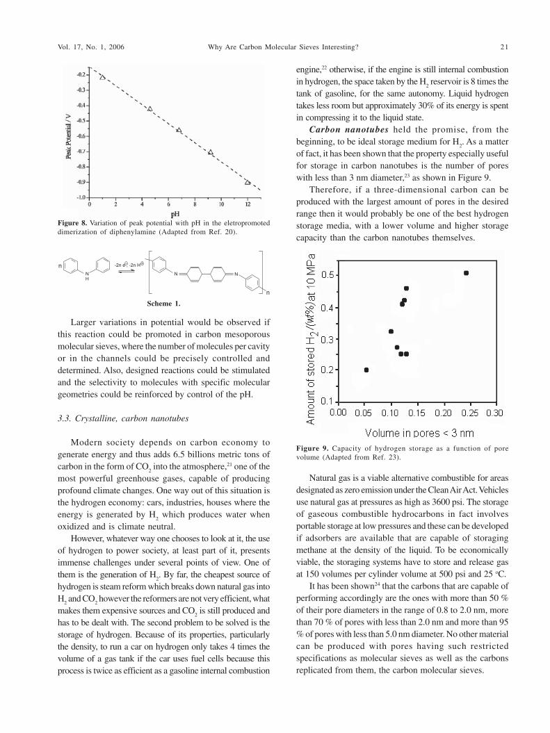
Carbon nanotubes held the promise, from thebeginning, to be ideal storage medium for H
2. As a matter
of fact, it has been shown that the property especially usefulfor storage in carbon nanotubes is the number of poreswith less than 3 nm diameter,23 as shown in Figure 9.
Therefore, if a three-dimensional carbon can beproduced with the largest amount of pores in the desiredrange then it would probably be one of the best hydrogenstorage media, with a lower volume and higher storagecapacity than the carbon nanotubes themselves.
Natural gas is a viable alternative combustible for areasdesignated as zero emission under the Clean Air Act. Vehiclesuse natural gas at pressures as high as 3600 psi. The storageof gaseous combustible hydrocarbons in fact involvesportable storage at low pressures and these can be developedif adsorbers are available that are capable of storagingmethane at the density of the liquid. To be economicallyviable, the storaging systems have to store and release gasat 150 volumes per cylinder volume at 500 psi and 25 oC.
It has been shown24 that the carbons that are capable ofperforming accordingly are the ones with more than 50 %of their pore diameters in the range of 0.8 to 2.0 nm, morethan 70 % of pores with less than 2.0 nm and more than 95% of pores with less than 5.0 nm diameter. No other materialcan be produced with pores having such restrictedspecifications as molecular sieves as well as the carbonsreplicated from them, the carbon molecular sieves.
Scheme 1.
Figure 8. Variation of peak potential with pH in the eletropromoteddimerization of diphenylamine (Adapted from Ref. 20).
Figure 9. Capacity of hydrogen storage as a function of porevolume (Adapted from Ref. 23).

22 Oliveira et al. J. Braz. Chem. Soc.
4. Microporous Carbons from Zeolites
These materials, which find application in storage andas supports or as electrodes, have been prepared fromfurfuryl alcohol, acrylonitrile, vinyl acetate and pyrene assources of carbon and zeolites L, X, Y, ZSM-5, mordeniteand beta, clays such as bentonite and MFI silicalite.Chemical vapour deposition is used after the firstimpregnation with one of the above carbon sources withthe aim of making the impregnation more uniform.
The polymerization is performed generally by heatingprocesses and the dissolution of the template is made inHF (40 %) followed by HCl (37 %).
The initial idea of synthesizing carbon in zeolites camefrom the preparation of the resins followed by theirpyrolysis in several zeolites.25 Figure 10 shows the resultsof such procedures, using the phenol/formaldehyde resin(phen/form) in zeolites Y, beta and L while Table 1, showsthe porosity characteristics for the zeolites and theresulting carbon materials.
It is observed that the three-dimensional zeolitesproduce carbon sieves that have surface areas larger thanthe zeolites themselves (see zeolites Y and beta in Figure10, Panel A, and the first and second entries in Table 1) andthat the monodimensional zeolite L gave carbon tubeswith approximately half of the template surface area (Figure10, Panel A, third entry in Table 1).
Panel B in Figure 10 shows a bimodal distribution ofsurface areas for the phenol/formaldehyde resin pyrolyzedat 900 °C. This is probably due to an incomplete filling of
the template pores with the carbon source; when the matrixis dissolved the pores that have not been filled collapsecompletely, generating larger pores.
Real replication of zeolite Y was achieved by Ma etal.27 when propylene CVD is performed after theimpregnation with furfuryl alcohol. The surface area inthis case is 3600 m2 g-1 and the pore volumes have valuesof 1.5 cm3 g-1. The interesting aspect in this case is that thediffraction for the (111) plane is still present in X-raydiffraction for the microporous carbon. Among themicroporous carbons prepared so far, this is the first casewhere organization is shown to that level.
5. Mesoporous Carbons from Molecular Sieves
In the case of mesoporous carbons, used for sensorsand biosensors and as templates for oxides insupercapacitors, the carbon sources are the same as theones used for the production of microporous solids as wellas two other cheaper sources: pitch and sucrose. Astemplates the mesoporous molecular sieves of the typeMCM, SBA and MSU are privileged, but silica gel andsilica nanoparticles are also employed.
The polymerization is performed generally by heatingprocesses, however, acid is used to assist the polymerizationin the case of sucrose. Template dissolution is performedas before, in HF (40 %) followed by HCl (37 %).
One case of a one pot synthesis of this material, Scheme2 has also been reported.28 In this procedure, the rate of pHdecrease is a crucial parameter since both sucrose andsilicate polymerize simultaneously. Thus, care should betaken not to favour a fast polymerization of silica becauseit will not entrap the sucrose nor favour sucrosepolymerization because, once polymerized, the carbonsource is large to be entrapped in the silica pores.
The material so obtained is not of the best quality possiblein terms of porosity. The surface area of these materials islarge, around 850 m2 g-1, of which 720 m2 g-1 are micropores.These carbons have large pore volumes (1.1 cm3 g-1) butpresent large macroporosity (0.26 cm3 g-1) probably due topacking of particles or lack of polymerization matching, asdiscussed above. Thus, the procedure to produce mesoporouscarbons, the most organized possible, has to follow the most
Table 1. Porosity properties for template zeolites and the microporouscarbon
Zeolitic Zeolite´s Carbon Carbon´s PoreTemplate surface Material surface volume
area m2 g-1 area m2 g-1 cm3 g-1
Y 488 C-Y 1580 0.83Beta 475 C-beta 641 0.33L 205 C-L 121 0.10
Figure 10. (A) Zeolites used as templates and the representation ofthe carbon materials prepared from them. (B) the pore sizes distri-bution of zeolites Y and beta and of the carbon materials (Adaptedfrom Refs. 25 and 26).

23Why Are Carbon Molecular Sieves Interesting?Vol. 17, No. 1, 2006
commonly used methods, the ones already used for thepreparation of microporous carbons.
Starting from MCM-48, Kruk et al.29 prepared mesoporouscarbons by impregnating the mesopores with sucrose in lowpH, thermally polymerizing it, pyrolysing it at 900 °C andthen dissolving the silica structure. The material preparedwas called CMK-1 (Carbon Mesostructure from Kaist). Figure11 shows some characteristics of the CMK-1 prepared in ourlaboratory using literature procedure.29
If carbon tubes are needed, the first idea is to use MCM-41 as template. However, this material presents un-connected mesopores, therefore, once filled with thecarbon precursor, pyrolysed and the matrix dissolved, thecarbon tubes will have no attachment to one other, andthen do not remain parallel.
A solution for this situation is the use of SBA-15,30 whichis also composed of parallel mesopores, the same way asMCM-41, but presents a set of micropores connecting thelarger pores. In this case, when the pores are filled with thecarbon precursor and the matrix is dissolved, the resultingmaterial, called CMK-3, presents a hexagonal organizationof parallel carbon tubes, Scheme 3.30,31
Figure 12 shows the transmission electron micrographsof the siliceous SBA-15 and of the final CMK-3 where it ispossible to confirm the presence of the paralell carbon rods.
Compared with the traditional particulate catalystsupports, the pore network of the synthesized mesoporousstructure is not obstructed by the carbon rods but the porosityis sustained by small carbon spacers that were originated bythe micropores connecting the mesopores in the SBA-15.
The CMK-3 has already been used as a material to supportPt for the cathode of a direct methanol fuel cell. The fuel cellthus prepared displayed a maximum power density of 61mW cm2 at 65 °C, comparable to the performance of the
Figure 11. (A) X-ray diffraction profiles of samples that result ineach step of CMK-preparation, a.) the MCM-48 template, b.) su-crose-impregnated MCM-48, c.) after pyrolysis at 600 °C, d.) afterpyrolysis at 900 °C, e.) after dissolution of the template of samplepyrolysed at 600 °C and f.) after dissolution of the template ofsample pyrolysed at 900 °C. (B) A scanning electron micrographs ofCMK-1 prepared at 900 °C. (C) Transmission electron micrographof the CMK-1 prepared at 900 °C. The inset shows the three dimen-sional structure of the pores. The circle in white shows a piece wherethe pores are more clearly seen; their organization corresponds tothe structure in the inset.
Scheme 2.
Scheme 3.

24 Oliveira et al. J. Braz. Chem. Soc.
conventional cells at 80 °C. The authors atributed this betterperformance to a more effective flow of gases and liquids,probably due to the fact that the surface area of CMK-3 is 800m2 g-1 while that of Vulcan XC-72 (E-tek carbon) is only 234m2 g-1. Therefore, a larger surface area and/or volume of(meso)pores is interesting for catalysts supports in fuel cells.
6. Macroporous Carbons from Silica Spheres
In the production of porous carbons, pitch is also an optionas carbon precursor in place of sugars, resins or polymers.32 Inthat case, meso/macroporosity imprinting occurs and can beplaced either at the surface or in the bulk of particles,depending on the synthesis procedure, Scheme 4.
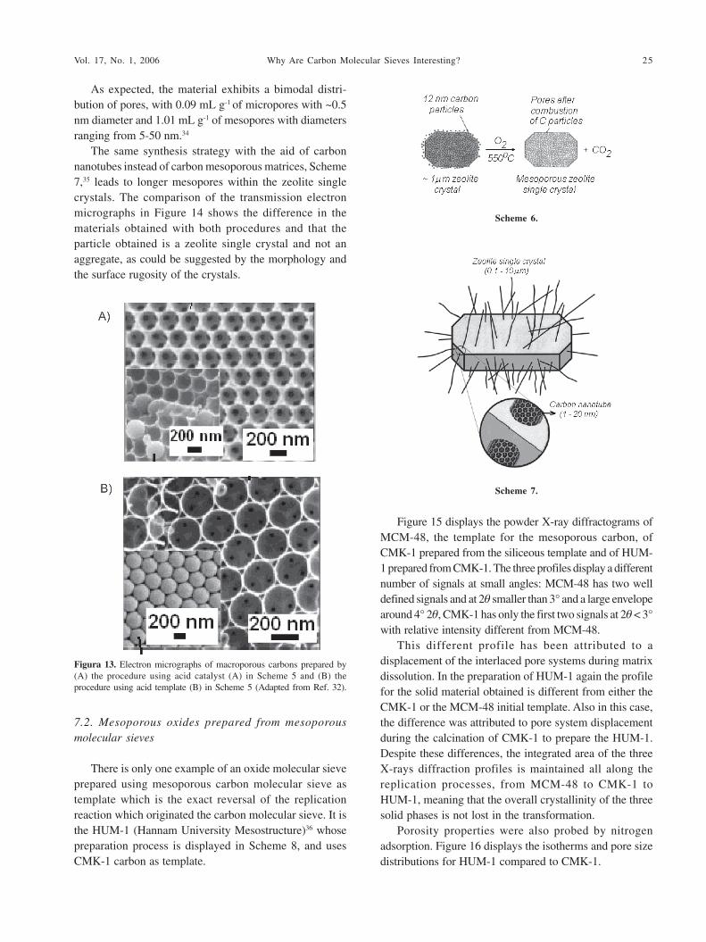
Spatially-resolved polymerization on silica spherescan also determine the type of porous carbon prepared.This effect can be obtained by careful control of thechemistry at the surface of the silica sphere,33 or at theinterface carbon precursor-silica, Scheme 5.
The polymerization of the phenol/formaldehyde resin isan acid catalysed reaction, thus an acid catalyst in the reactionmedium causes total polymerization except where the silicaparticles are (Path A in Scheme 5). However, if only the surfaceof the silica sphere is made acidic, an acid template, as forinstance by reaction with aluminum tri-isopropoxide, thenthe polymerization will take place only at the silica-carbonprecursor interface (Path B in Scheme 5). The electron
microscopies in Figure 13 show the results of both processes.In Figure 13A it is observed that the material resembles
a hexagonal array of pores whereas Figure 13B shows amaterial where the carbon phase is only a layer at the surfaceof the particles, thus proving the possibility of spatialresolution of the polymerization/carbonization process.
7. Porous Metal Oxides Prepared from PorousCarbons and Carbon Molecular Sieves
7.1. Mesoporous zeolite single crystals
Zeolites are known as excelent catalysts and catalystsupports with one major drawback, which is the lack ofreactivity towards molecules larger than their windows andpores. One way to circumvent such a disadvantage is toprepare zeolite particles with mesopores in the crystalsthemselves, the mesoporous zeolite single crystals.34 In orderto prepare such materials, one way is to crystallize zeoliteswithin the pores of a carbon mesoporous matrix in excessgel. Crystals are nucleated in the mesopore system and growto large zeolite crystals around the carbon particles.Calcination eliminates the carbonaceous counterpart andliberates the zeolite mesopores (Scheme 6).
Scheme 5.
Figure 12. Transmission electron micrographs of (A) SBU-15 and(B) CMK-3 (Adapted from Ref. 30).
Scheme 4.
25Why Are Carbon Molecular Sieves Interesting?Vol. 17, No. 1, 2006
As expected, the material exhibits a bimodal distri-bution of pores, with 0.09 mL g-1 of micropores with ~0.5nm diameter and 1.01 mL g-1 of mesopores with diametersranging from 5-50 nm.34
The same synthesis strategy with the aid of carbonnanotubes instead of carbon mesoporous matrices, Scheme7,35 leads to longer mesopores within the zeolite singlecrystals. The comparison of the transmission electronmicrographs in Figure 14 shows the difference in thematerials obtained with both procedures and that theparticle obtained is a zeolite single crystal and not anaggregate, as could be suggested by the morphology andthe surface rugosity of the crystals.
7.2. Mesoporous oxides prepared from mesoporousmolecular sieves
There is only one example of an oxide molecular sieveprepared using mesoporous carbon molecular sieve astemplate which is the exact reversal of the replicationreaction which originated the carbon molecular sieve. It isthe HUM-1 (Hannam University Mesostructure)36 whosepreparation process is displayed in Scheme 8, and usesCMK-1 carbon as template.
Figure 15 displays the powder X-ray diffractograms ofMCM-48, the template for the mesoporous carbon, ofCMK-1 prepared from the siliceous template and of HUM-1 prepared from CMK-1. The three profiles display a differentnumber of signals at small angles: MCM-48 has two welldefined signals and at 2θ smaller than 3° and a large envelopearound 4° 2θ, CMK-1 has only the first two signals at 2θ < 3°with relative intensity different from MCM-48.
This different profile has been attributed to adisplacement of the interlaced pore systems during matrixdissolution. In the preparation of HUM-1 again the profilefor the solid material obtained is different from either theCMK-1 or the MCM-48 initial template. Also in this case,the difference was attributed to pore system displacementduring the calcination of CMK-1 to prepare the HUM-1.Despite these differences, the integrated area of the threeX-rays diffraction profiles is maintained all along thereplication processes, from MCM-48 to CMK-1 toHUM-1, meaning that the overall crystallinity of the threesolid phases is not lost in the transformation.
Porosity properties were also probed by nitrogenadsorption. Figure 16 displays the isotherms and pore sizedistributions for HUM-1 compared to CMK-1.
Figura 13. Electron micrographs of macroporous carbons prepared by(A) the procedure using acid catalyst (A) in Scheme 5 and (B) theprocedure using acid template (B) in Scheme 5 (Adapted from Ref. 32).
Scheme 7.
Scheme 6.

26 Oliveira et al. J. Braz. Chem. Soc.
CMK-1 presents pores with a very narrow distribution ofsizes which are replicated into larger pores and of a morevariable size distribution. Whatever the replication results interms of size distribution are, the porosity of the siliceousmaterial is clear and confirms the potential of this process toproduce porous materials with compositions that were difficultto obtain by conventional processes of wet chemistry.
Micro- or mesoporous catalysts with intrinsic basicproperties are difficult to obtain. Such catalysts are usuallyprepared by post-synthesis grafting of basic compounds.37,38
Therefore, possibility to use microporous and mesoporouscarbon molecular sieves as templates in replicationprocesses comes in due time. In fact, recently CMK-3 wasused as a template for the production of mesoporous MgOby a replication method called, by the authors, asexotemplating.39 The CMK-3 carbon was prepared fromSBA-15. Figure 17 shows the powder X-ray diffractionprofiles of the three materials.
Despite the apparent decreased ordering in themagnesium oxide phase as detected by XRD, thetransmission microscopy showed long range order with
Figure 14. Transmission electron micrographs of silicalite preparedusing (A) mesoporous carbon matrix according to Scheme 6(Adapted from Ref. 34) and (B) carbon nanotubes according toScheme 7 (Adapted from Ref. 35). The insert in Panel A shows thatthe particle is indeed one single crystal and not an aggregate.
Scheme 8.
Figure 15. X-ray diffraction of the three solid phases obtained by consecutive replication processes, from siliceous MCM-48 to carbon CMK-1 and to siliceous HUM-1, along with the transmission electron micrographs for the first and the third phases (Adapted from Ref. 36).

27Why Are Carbon Molecular Sieves Interesting?Vol. 17, No. 1, 2006
hexagonal symmetry of pores. Nitrogen physisorptionfurther reveals the porous nature of the solid. The porevolume amounts to 0.51 cm3 g-1.
The desorption of chemisorbed CO2 in flowing helium
occurs in a temperature range up to 300 °C, which confirmsa degree of basicity comparable to MgO-coated SBA-15.38
8. Challenges and Perspectives
As a matter of fact, the challenges in the field aremore of a multiplying type in the sense that, for instance,for replication into carbon of a microporous material, theonly unquestionable example is zeolite Y, with a surfacearea of the order of 3000 m2g-1. The replication ofmesoporous materials seems to be less of a problem,however, for the replication of mesoporous carbonmolecular sieves into cilicas, again only one example,the HUM-1, is known. Therefore, from this point of view,more examples are needed to confirm the generalapplicability of the synthesis method.
A second challenge, and the one of a more innovativecharacter, involves the discovery of graphitizationmethods to organize the amorphous carbonaceous wallsof the carbon molecular sieves. This would improve theconductivity of these materials. A number of papers haveappeared describing the preparation of porous carbonswith crystalline frameworks; despite the success inobtaining crystalline walls the surface areas reported arevery poor.40-42 Therefore, this is another field that needsintense research if a porous conductive material is to beprepared.
It has been proposed that if tiny pairs of carbon cathodeand anode could be assembled in three dimensional arrays,
then the power released by the batteries could be multipliedby the number of pairs of anodes available,16 leading toeven smaller palm tops, celular phones, clocks, etc.16 Oneway to assemble these pairs is to build them from carboninto the pores of molecular sieves that have independent,non-crossing channel systems, such as MCM-22, forinstance. If other than this, the carbonaceous phase isgraphitized, then three dimensional batteries will be moreat hand than ever.
Acknowledgments
The authors acknowledge the work, dedication andentusiasm of several graduate and undergraduate studentsthat are always part of the Micro and MesoporousMolecular Sieves Group.
Figure 17. (A) X-ray diffraction of the parent SBA-15 silicate, ofCMK-3 carbon, the exotemplate, and the MgO final material. (B)transmission electron microscopy of the mesoporous MgO (scalebar = 60 nm) (Adapted from Ref. 39).
Figure 16. N2
adsorption isotherms for the CMK-1 carbon and thesiliceous HUM-1. In the insert, the pore size distributions for bothmaterials (Adapted from Ref. 36).

28 Oliveira et al. J. Braz. Chem. Soc.
5. Burkett, S. L.; Davis, M. E.; J. Phys. Chem. 1994, 98, 4647.
6. Pastore, H.O.; Munsignati, M.; Rippel, M. M.; Bittencourt, D.;
Microporous Mesoporous Mater. 1999, 32, 211.
7. Kresge, C.T.; Leonowicz, M. E.; Roth, W. J.; Vartuli, J. C.;
Beck, J. S.; Nature 1992, 359, 710.
8. Albuquerque, A.; Vautier-Giongo C.; Pastore, H. O.; J. Colloid
Interface Sci. 2005, 284, 687.
9. Ruggles, J. L.; Holt, S. A.; Reynolds, P. A.; White, J. W.;
Langmuir 2000, 16, 4613
10. Pekala R. W.; Hopper, R. W.; J. Mater. Sci. 1987, 22, 1840.
11. Hu, Z.; Vansant, E. F.; Carbon 1995, 33, 561.
12. Lenghaus, K.; Qiao, G. G.-H.; Solomon, D. H.; Gomez, C.;
Rodriguez-Reinoso, F.; Sepúlveda-Escribano, A.; Carbon
2002, 40, 743.
13. Villar-Rodil, S.; Martínez-Alonso, A.; Tascón, J. M. D.; J.
Colloid Interface Sci. 2002, 254, 414.
14. Vu, D. Q.; Koros, W. J.; Miller, S. J.; J. Membr. Sci. 2003, 211,
311.
15. García-Bordeje, E.; Calvillo, L.; Lazaro, M. J.; Moliner, R.;
Ind. Eng. Chem. Res. 2004, 43, 4073.
16. Long, J. W.; Dunn, B.; Rolison, D. R.; White, H. S.; Chem. Rev.
2004, 104, 4463.
17. Wakihara, M.; Mater. Sci. Eng. Reports 2001, 33, 109.
18. Winter, M.; Brodd, R. J.; Chem. Rev. 2004, 104, 4245.
19. For one example see: Fine Cell and Viable Korea Co, Intern.
Patent 89991 2001.
20. Leventis, H. C.; Streeter, I.; Wildgoose, G. G.; Lawrence, N.
S.; Jiang, L.; Jones, T. G. J.; Compton, R.G.; Talanta 2004, 63,
1039.
21. Kennedy, D.; Science 2004, 305, 917.
22. Service, R. F.; Science 2004, 305, 958.
23. Bacsa, R.; Laurent, C.; Morishima, R.; Suzuki, H.; Le Lay, M.;
J. Phys. Chem. B 2004, 108, 12718.
24. Westvaco Co. US. Patents 5,626,637 1995; Niagara Mohawk
Power Co. US. Patents 6,225,257 1999.
25. Johnson, S. A.; Brigham, E. S.; Ollivier, P. J.; Mallouk, T. E.;
Chem. Mater. 1997, 9, 2448.
26. Fuertes A. B.; Nevskaia, D. M.; Microporous Mesoporous Mater.
2003, 62, 177.
27. Ma, Z.; Kyotani, T.; Liu, Z.; Terasaki, O.; Tomita, A.; Chem.
Mater. 2001, 13, 4413.
28. Han, S.; Carbon, 2003, 41, 1525.
29. Kruk, M.; Jaroniec, M.; Ryoo, R.; Joo, S. H.; J. Phys. Chem. B
2000, 104, 7960.
30. Zhao, D. Y.; Feng, J. L.; Huo, Q. S.; Melosh, N.; Fredrickson,
G. H.; Chmelka, B. F.; Stucky, G. D.; Science 1998, 279, 548
31. Nam, J.-H.; Electrochem. Commun. 2004, 6, 737.
32. Jaroniec M.; Li, Y.; WO 006372 2003.
33. Yu, J.-S.; Kang, S.; Yoon, S. B.; Chai, G.; J. Am. Chem. Soc.
2002, 124, 9382.
34. Jacobsen, C. J. H.; Madsen, C.; Houzvicka, J.; Schmidt, I.;
Carlsson, A.; J. Am. Chem. Soc. 2000, 122, 7116.
Cléo Thomás Gabriel V. M. T. Pires was
born in 1983, in Brazil. He obtained his
B. Sc. Degree in Chemistry (2004) at the
University of Brasilia and joined the
Micro- and Mesoporous Molecular Sieves
Group, at Campinas, in the same year.
He is presently working for his Masters
Thesis on the synthesis and characterization of micro- and
mesoporous carbon and others studies in the area of porous
materials. In the year of 2006 he starts his Ph.D work.
Érica Cristina de Oliveira graduated from
the University of São Paulo at Ribeirão Preto,
where she undertook also her Masters
Degree. In 1998 she joined Prof. Pastore´s
group for her PhD in organometallics
anchoring in zeolites and its use as catalyst
for C-H and C-N activation. Her Post-
Doctoral work was mainly devoted to different procedures to obtain
porous carbons where the pores walls where composed as much as
possible of graphite-like moieties. She is presently working at the
Aeronautics Technological Centre, at São José dos Campos, SP.
Heloise de Oliveira Pastore has been based
in the Inorganic Chemistry Department, at
the Chemistry Institute of the State
University of Campinas, where at the
moment she is Associated Professor, since
1994. Her research interests include the
synthesis and modification of micro and
mesoporous materials and layered structures. The organization of
molecules and entities at, and by, inorganic oxide materials, especially
molecular sieves are currently being actively studied in her group,
with the aim at creating nanosystems capable of light emission or
electronic conduction. Molecular sieves are also studied as sacrificial
templates for the preparation of carbon nanoparticles or carbon
molecular sieves for the use in fuel cells and electrodes in general. She
is the head of the Micro- and Mesoporous Molecular Sieves Group.
References
1. Marsh, H.; Crawford, D.; O´Grady, T. M.; Wennerberg, A. N.;
Carbon 1982, 15, 419.
2. Grunewald, G. C.; Drago, R. S.; J. Am. Chem. Soc. 1991, 113,
1636.
3. Wulff G.; Sharhan, A.; Angew. Chem., Int. Ed. Eng. 1972, 11, 341.
4. Sibrian-Vazques, M.; Spivak, D. A.; J. Am. Chem. Soc. 2004,
126, 7827.

29Why Are Carbon Molecular Sieves Interesting?Vol. 17, No. 1, 2006
35. Schmidt, I.; Boisen, A.; Gustavsson, E.; Stahl, K.; Pehrson, S.;
Dahl, S.; Carlsson, A.; Jacobsen, C. J. H.; Chem. Mater. 2001,
13, 4416.
36. Kim, J. Y.; Yoon, S. B.; Yu, J.-S.; Chem. Mater. 2003, 15,
1932.
37. Wang, Y.; Zhu, J. H.; Cao, J. M.; Chun, Y.; Xu, Q. H.;
Microporous Mesoporous Mater. 1998, 26, 175.
38. Wei, Y. L.; Wang, Y. M.; Zhu, J. H.; Wu, Z. Y.; Adv. Mater.
2003, 15, 1943.
39. Roggenbuck, J.; Tiemann, M.; J. Am. Chem. Soc. 2005, 127,
1096.
40. Han, S.; Yun, Y.; Park, K.; Sung Y.; Hyeon, T.; Adv. Mater.
2003, 22, 1922.
41. Kim, T.; Park S.; Ryoo, R.; Angew. Chem., Int. Ed. 2003, 42,
4275.
42. Hyeon, T.; Han, S.; Sung, Y.; Park K.; Kim, Y.; Angew. Chem.,
Int. Ed. 2003, 42, 4352.
Received: April 26, 2005
Published on the web: December 1, 2005
FAPESP helped in meeting the publication costs of this article.