Embed Size (px)
Citation preview

/ ^ UCRL-10526 c ->
University of California
Ernest O. Lawrence Radiation Laboratory
MAGNETIC ANALYSIS OF ATOMIC AND MOLECULAR BEAMS.
I. CONSTRUCTION AND CALIBRATION OF INHOMOGENEOUS DEFLECTING MAGNETS
Berkeley, California

UCRL-10526 UC-34 Physics
TID-4500 (18th Ed. )
UNIVERSITY O F CALIFORNIA
Lawrence Radiation Labora tory Berkeley, California
Contract No, W-7405-eng-48
MAGNETIC ANALYSIS OF ATOMIC AND MOLECULAR BEAMS.
I. CONSTRUCTION AND CALIBRATION OF
INHOMOGENEOUS DEFLECTING MAGNETS
Ronald R. Herm and Dudley R, Herschbach
October, 1962
LEGAL N O T I C E I TMB report was prepared ae an account ot Government sponsored work Neither the United 1 States, nor the ComraiBSLon, nor any person acting on behalf of the ComndsBlon 1 A. Makes any warranty or repreaenWUon, expressed or implied, with respect to the accu-\ racy, completeness, or usefulnees of the information contained In this report, or that the use
of any InlormaUon, apparatus, method, or procesa disclosed In this report may not Infringe
I privately owned rights, or I B Assumes any UabiUtlea with respect to the use ol. or lor dam^gea resulting from the I use of any Information, apparatus, method, or process disclosed In this report
As used In the above, "person acting on behalf of the Commission" includes any employee or contractor of the Commission, or employee ol such contractor, to the extent that
I such employee or contractor of the Commission, or employee of such contractor prepares, I disseminates, or provides access to, any InlormaUon pursuant to his employment or contract I with the Commission, or his employment with such contractor

DISCLAIMER
This report was prepared as an account of work sponsored by an agency of the United States Government. Neither the United States Government nor any agency Thereof, nor any of their employees, makes any warranty, express or implied, or assumes any legal liability or responsibility for the accuracy, completeness, or usefulness of any information, apparatus, product, or process disclosed, or represents that its use would not infringe privately owned rights. Reference herein to any specific commercial product, process, or service by trade name, trademark, manufacturer, or otherwise does not necessarily constitute or imply its endorsement, recommendation, or favoring by the United States Government or any agency thereof. The views and opinions of authors expressed herein do not necessarily state or reflect those of the United States Government or any agency thereof.

DISCLAIMER Portions of this document may be illegible in electronic image products. Images are produced from the best available original document.
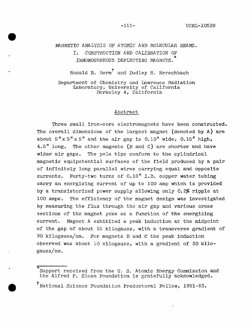
-111- UCRL-10526
mONETIC ANALYSIS OF ATOMIC AND MOLECULAR BEAMS.
I, CONSTRUCTION AND CALIBRATION OF
INHOMOGENEOUS DEFLECTING MAGNETS.
+ Ronald R. Herm and Dudley R. Herschbach
Department of Chemistry and Lawrence Radiation Laboratory, University of California
Berkeley 4, California
Abstract
Three small iron-core electromagnets have been constructed*
The overall dimensions of the largest magnet (denoted by A) are
about 5"x5"x5" and the air gap is 0.10" wide, 0.15" high,
4.5" long. The other magnets (B and c) are shorter and have
wider air gaps. The pole tips conform to the cylindrical
magnetic equipotential surfaces of the field produced by a pair
of infinitely long parallel wires carrying equal and opposite
currents. Forty-two turns of 0.18" I.D. copper water tubing
carry an energizing current of up to 100 amp which is provided
by a transistorized power supply allowing only 0.2^ ripple at
100 amps. The efficiency of the magnet design was Investigated
by measuring the flux through the air gap and various cross
sections of the magnet yoke as a function of the energizing
current. Magnet A exhibited a peak Induction at the midpoint
of the gap of about 15 kilogauss, with a transverse gradient of
90 kilogauss/cm. For magnets B and C the peak Induction
observed was about 10 kiloga,uss, with a gradient of 30 kilo
gauss/cm.
Support received from the U. S. Atomic Energy Commission and the Alfred P. Sloan Foundation is gratefully acknowledged. t National Science Foundation Predoctoral Fellow, 1961-63.

-1-
INTRODUCTION
In a magnetic field Hj» a neutral atom or molecule with
magnetic moment jJ. acquires potential energy,
W = -M; • H (l)
and Is accelerated by a force,
P = -V W. (2)
As the only significant dependence of W on position is through
the spacial inhomogenity of the field.
The coefficient Sw/dH differs for each of the 2J+ 1 magnetic
Bubstates arising from the various possible orientations of
the angular momentum of the molecule, J, and the magnetic field.
Thus, if an atomic or molecular beam is sent transversely
thi*ough an Inhomogeneous magnetic field, the beam splits into
components corresponding to the various magnetic substates,
and each component beam undergoes a deflection determined by
the path length and field gradient and by the mass and velocity
of the molecules.
The analysis of beams by magnetic deflection is a venerable
technique,l""^ first used in the celebrated Stern-Gerlach

-2-
experiment of 1921 which demonstrated the spacial quantization
of angular momentum. The aspect most fully exploited has been
the selection of magnetic substates, as Rabi developed from
this a general method of radiofrequency spectroscopy which has
provided hundreds of measurements of nuclear, atomic, and
molecular magnetic moments.
In molecular beam scattering experiments, however, there
has been little use of magnetic analysis. Three applications
of particular interest in this laboratory will be briefly
described.
Scattering of magnetically aligned beams. If the electron
spins in colliding beams of J = p- atoms were aligned parallel
or antiparallel in successive experiments, a direct comparison
of the scattering in the triplet and the singlet states could
be made. The intensity limitations do not appear to be pro
hibitive for beams of alkali metal atoms, for example. The
probability of "spin flip" collisions can be studied with dne
5 1
aligned beam. If one of the colliding atoms has J >^> the
dispersion interaction will be noncentral, and the anlsotropy
of the potential can be studied by use of magnetic analysisi
such an experiment has recently been carried out be Berkling^
Schlier, and Toscheko
Separation of paramagnetic and diamagnetlc species. In
crossed beam studies of chemical reactions, such as
K + Ig -—>- I + KI,

-3-
the detector must distinguish between the elastically scattered
K atoms and reactively scattered KI. The most sensitive avail
able detector uses surface ionization on hot filaments, which
produces K ions from both K and KI. By comparing readings
from filaments which differ in ionization efficiency for K and
KI, they can be successfully distinguished, but this method
gives somewhat erratic results, especially in regions where the 7
background of elastically scattered K is large. Another
approach would be to place a small, strongly inhomogeneous
magnet between the scattering center and the detector. This
would permit most of the K signal to be "switched on and off"
at will, with virtually no effect on the KI signal. In many
experiments such a "magnetic filter," might be placed across
the exit of a beam oven in order to "purify" the beam. For
example, in the reaction
Kg + I - ^ K + KI,
the K atoms emitted by the oven would be deflected out and a
Kg beam transmitted by the filter. Magnetic analysis has been
used in several beam studies of the dimerization equilibria
of alkali atoms. Including 2K ?=2 Kg, and also in studies of
9 9 the dissociation equilibria of hydrogen, nitrogen, and
10 fluorine molecules.
Velocity selection^ Magnetic deflection of a beam
provides velocity analysis as. a bonuso Although in practice
mechanical selectors usually give better resolution, they
-4-
become awkward above about 3x10 cm/sec and probably Impractical
above about 10 cm/sec. Thus, magnetic velocity selection is
particularly attractive for high temperature beams of light
6 / atoms. For example, hydrogen atoms moving at 5 x 10 cm/sec
(15 electron volts) will undergo a usable deflection of 0.027
cm on passing through a field 50 cm long with a gradient of
100 kilogauss/cm. An early analysis of magnetic velocity
selection was given by Cohen and Ellett, and this has
12 recently been extended by Bederson and Rubin, who are
especially concerned with high velocity beams.
This report describes the details of construction and
calibration of three small, strongly inhomogeneous magnets
(referred to as A, B, and C) to be used in experiments of the
sort outlined above. The deflecting power of these magnets
is Indicated in Fig. 1; however, we shall defer to a subsequent
report (Part II of this series) a detailed treatment of the
deflection patterns, velocity resolution, and other operational
characteristics of the magnetp.
MAGNET CONSTRUCTION
A photograph of the largest of the magnets (magnet A,
4.6 inches in length) Is shown in Fig. 2.
Pole Tips
The surfaces of the pole tips conform to the "outside"
and "inside" of two cylinders differing in radius and axis.
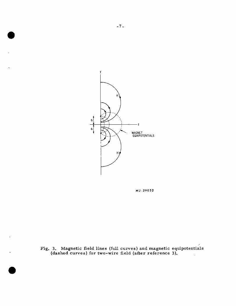
As illustrated in Fig. 3, these belong to the family of magnetic

- 5 -
,2 00254 0127 0 254 DEFLECTION IN
127 2.54
2 4 6 8|o2 DEFLECTION
MU 29031
1. Deflecting power of magnets (at 100 ampere excitation, see Fig. 13). The hypothetical "magnet A*" is the same as A but 50 cm in length.

ZN-3452
Fig. 2. Photograph of magnet A. The ove r -a l l dimensions of the magnet a r e about 5"X5"X5".
-7 .
MAGNET EQUIPOTENTIALS
M U - 2 9 0 3 2
Fig. 3. Magnetic field l ines (full curves) and magnetic equipotentials (dashed curves) for two-wire field (after re fe rence 3).

-8-
equipotential surfaces of the field produced by two Infinitely
long parallel conductors of infinitesimal diameter carrying
equal but opposite currents. Also shown in Fig, 3 are the
lines of magnetic force, which constitute a second, orthogonal
family of cylinders.
This "two-wire field, which has become standard for 3 4 molecular beam deflecting magnets, ' was introduced by Rabi,
13 Kellogg, and Zacharias. As they actually used wires, the
field and transverse field gradient at any point could be
14 calculated from the current as
H = 21 - r ^ (4) ^r2
and
where I is one-tenth the current in amperes and the geometrical
quantities are defined in Fig. 4. An advantage of this type
of field over that originally used by Stern and Gerlach is
that for z > 1.1a H and ^I^^z vary only slightly with the
coordinate y (parallel to the tall dimension of the beam)
between y = -0.7a to +0.7a. Thus a tall, ribbon-shaped beam
can De used and it will be deflected sideways with very little
vertical distortion as long as it does not pass too close to
the convex pole tip. Because of the high current densities
required, the maximum field attainable with the two-wire
arrangement is only about one kilogauss (unless superconducting
wire were to be used). Adding iron to the magnetic circuit

*-z
M U - 2 9 0 3 3
Fig. 4. Definition of coordinate sys tem.

-10-
of course leads to much stronger fieldsj 10-15 kilogauss at
3 4 saturation is typically obtained. *
An iron core magnet employing the cylindrical "Rabi pole
tips" should produce a field in the air gap with virtually
the same families of equipotential surfaces and lines of
magnetic force as the equivalent two-wire field. Although
it is no longer possible to calculate the field produced by
a given energizing current, the ratio of the transverse field
gradient to the field Is determined solely by geometrical
parameters,
^H/^z _ H
In the plane y = 0,
2 2 ^1 = ^2 =
and
^H/^Z _ H
Our magnets were designed to give
^ ^ ^ a 6, for magnet A
and
^ ^ ~ 3, for magnets B and C
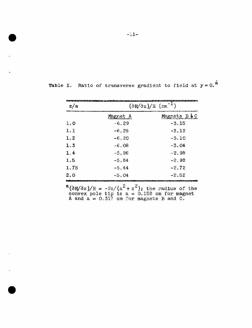
at z = 1.2a, the customary beam position. In Table I the
ratios calculated from Eq. (7) for y = 0 and various values
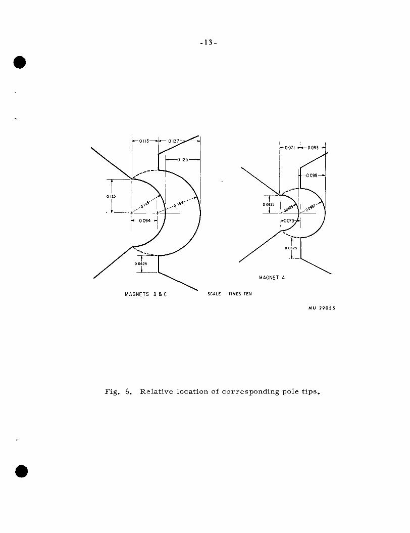
of z are given. Figs. 5 and 6 show the dimensions and relative
2 . 2 ^1+^2 2 2
^1 2
2 2 a + z
2z 2 2 • a + z
(6)
(7)
-11-
Table lo Ratio of transverse gradient to field at j - 0 .
z/a (an/dz)/H (cm )
l o O
l o l
1=2
l o 3
1„4
1,5
1«75
2..0
Magnet A — Do 2 9
- 6 „ 2 6
- 6 o 2 0
- 6 o 0 8
- 5 o 9 6
- 5 c 8 4
~5o44
~5o04
Magnets B l» C
-3c 15
•™ tkj o J L O
- 3 . 1 0
- 3 o 0 4
- 2 o 9 8
- 2 » 9 8
- 2 o 7 2
- 2 o 5 2
^(b}i/hz)/E = -2z/(a +z^)3 the radius of the convex pole tip is a = 0<.158 cm for magnet A and a = 0o317 cm for magnets B and C»

- 1 2 -
»- 0.590-"
' -^ RADIUS^'* , I* -jz RADIUS
31 32
•-0.S63--
\1 s J
•-0.586-"
1—0 J3J
^^ ±-JL
^ \ n-'<^ - " — " ^ -i-RADIUS^ '- 5 > ! " - ^ RADIUS-^
^ ,±
MAGNET B
M U - 2 9 0 3 4
Fig. 5. Dimensions of pole t ips .
- 1 3 -
MAGNET A
MAGNETS B a C SCALE TIMES TEN
MU 2 9 0 3 5
Fig. 6. Relative location of corresponding pole t ip s .

-14-
posltions of the pole tips. The tolerance in vertical align
ment (y-coordinate) of the pairs of pole tips was less than
0.005". Variations In the horizontal alignment (z-coordinate)
were only slightly larger. The maxlmxim width of the air gaps
was measured after the final assembly:
For magnet A 0.0990-0.0995"
B 0.1235-0.1245"
C 0.1260-0.1265"
Details of Fabrication
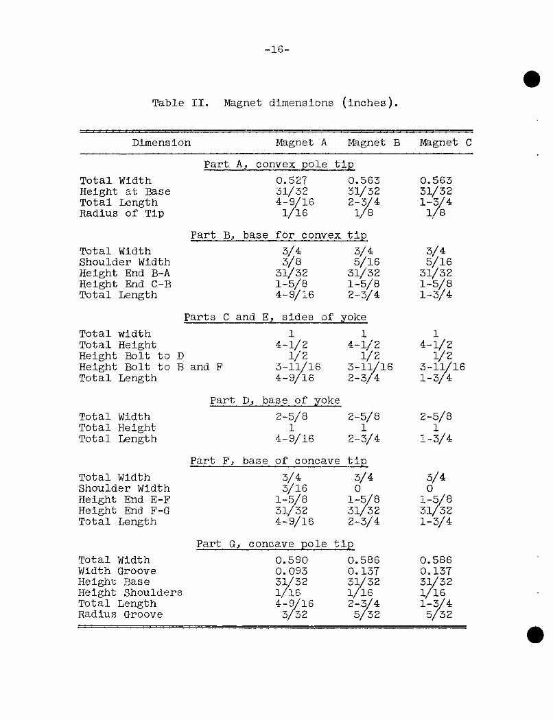
Fig. 7 is an assembly drawing for the magnets, and Table
II gives in detail the dimensions of the various parts. The
pole tips (parts A and G) are mounted on base pieces (parts
B and F ) by means of external clamps, and the various sections
of the yoke (parts B, C, D, E, P) are bolted together. Braces
(shown in Fig. 2) were added to prevent deformation of the
yoke. The tips are Western Electric Permendur, the yoke parts
are Armco ly gnetic Ingot Iron, and the clamps and braces are
Stainless Steel. All the iron parts (A to G) were nickel
plated to prevent rusting.
The energizing current and cooling water is carried by
forty-two turns of 3/l6" I.D. copper tubing wound about the
yoke, twenty-one turns about each of the sides (parts C and E).
Teflon sheet is inserted between the coils and yoke to prevent
chafing, and the tubing is insulated with fiberglass sheathing
(see Pig. 2).

- 1 5 .
MAGNETS B a C
l-f
-20 TAP 4- DEEP
MAGNET A
MU-29036
Fig. 7. Assembly drawing for magne ts .
-16-
Table I I . Magnet dimensions ( inches) .
Dimension Magnet A Magnet B mgnet C
Part A, convex pole t i p Total Width 0.527 0.563 0.563 Height at Base 31/32 31/32 31/32 Total Length 4-9/16 2-3/4 1-3/4 Radius of Tip 1/16 1/8 1/8
Part B, base for convex t i p Total Width 3/4 3/4 3/4 Shoulder Width 3/8 5/16 5/16 Height End B-A 31/32 31/32 31/32 Height End C-B 1-5/8 1-5/8 1-5/8 Total Length 4-9/16 2-3/4 1-3/4
Parts C and E, sides of yoke
Total width 1 1 1 Total Height 4-1/2 4-1/2 4-1/2 Height Bolt to D l / 2 l / 2 1/2 Height Bolt to B and P 3-11/16 3-11/16 3-11/16 Total Length 4-9/ l6 2-3/4 1-3/4
Part D, base of yoke Total Width 2-5/8 2-5/8 2-5/8 Total Height 1 1 1 Total Length 4-9/16 2-3/4 1-3/4
Part F, base of concave t i p Total Width 3/4 3/4 3/4 Shoulder Width 3/16 0 0 Height End E-F 1-5/8 1-5/8 1-5/8 Height End P-G 3l/32 3l/32 31/32 Total Length 4-9/16 2-3/4 1-3/4
Part G, concave pole t i p Total Width 0.590 0.586 0.586 Width Groove 0.093 0.137 0.137 Height Base 31/32 31/32 31/32 Height Shoulders 1/16 l / l 6 1/16 Total Length 4-9/16 2-3/4 1-3/4 Radius Groove 3/32 5/32 5/32

-17-
Power Supply
The energizing current is furnished by a transistorized,
regulated DC power supply capable of delivering 0-100 amps at
15 0-10 volts. Tests of the supply show it allows ripple of 5
0.15 amps RMS, short terra fluctuations of one part in 10 ,
and long term fluctuations of one to five parts in 10 over
one-half to one hour.

-18-
METHOD OP CALIBRATION
A search coil technique was used to measure the flux
through various regions of the magnetic circuito The principles
involved are well-known, but will be reviewed briefly. The
flux through a coil composed of N loops of wire which enclose
an area A is
«> = NAB, (8)
where B denotes the component of the magnetic induction normal
to the area of the colic B is assumed to be constant over the
ooil» A change in the flux induces an EMP given by
E - - ,
and therefore
dB _ E _ Ri _ R dQ /Q\
where R is a standard resistance in series with the induced
EMPi, 1 is the current in R, and Q is the charge developed
across a capacitor C in series with R., If the polarity of
the field is reversed during the time interval T,
T B Q
r (-dB/dt)dt = - r dB = (VN A ) J dQ 0 -B 0
2B = - ( V N A ) Q
or
B = - 2 m - ^ (10)

-19-
where V is the voltage developed across the capacitance as
a consequence of the Integrated EMF.
Diagrams of the actual circuits employed are given In
Pigs. 8 and 9. Search coils were placed about various parts
of the magnet and the normal component of the magnetic Induction
in each coil was determined as a function of the energizing
current supplied to the magnet. B was evaluated from Eq. (10)
by measuring the voltage V developed in the Integrating
circuit of Fig. 9 when the polarity of the energizing current
was reversed. The energizing current was determined from the
IR drop across an oil-cooled resistance (O. 010000 absolute
ohms) in series with the magnet coils.
Figure 10 shows the positions of the various search coils.
The coils were made of 0.0054" diameter copper wire. The area
of any of the coils about the iron core was taken as the
cross-sectional area of the core at the position of the coil.
The dimensions of the search coils used In the air gap are
shown in Pig. 11, These coils were securely fixed with respect
to the air gap boundaries by means of plastic spacers, as
indicated in Pig. 12. The area of each search coil used in
the air gap was measured in an auxiliary experiment employing
a homogeneous permanent magnetic field. The voltage V„
developed in the integrating circuit when the search coil was
rotated through 180° in this field was measured, and compared
with the voltage VQ produced by rotating a standard coil of
known area, A„. The area of the search coll was then taken as
A = (V3/V0) AQ-

- 2 0 -
CONSTANT CURRENT POWER SUPPLY
V - 6 4 DIGITAL VOLTMETER
SWITCH TO REVERSE POLARITY
-STANDARD RESISTOR 0.010000 Abs. ohms
ENERGIZING COILS OF MAGNET
PROBE COIL
INTEGRATING CIRCUIT
MU-29037
8. Schematic d iagram of c i rcui t employed in field m e a s u r e m e n t s .

- 2 1 -
ZERO RESET BUTTON
OUTPUT
M U - 2 9 0 3 8
Fig. 9. Schematic d iagram of integrat ing c i rcui t . R and C a r e var iab le . The drift control compensates for t he rma l E M F ' s ; the zero r e s e t d i scharges the capaci tor ; the input switch se lec ts the source and polarity of the input signal.

-22.
LOOP E LOOP D
LOOP F
LOOP C
LOOP A IS IN AIR GAP
ENERGIZING COILS 21 TURNS ABOUT
EACH SIDE
M U - 2 9 0 3 9
Fig. 10. Location of sea rch coi ls .

•23 -
i A
i B
1 C
i D
0.0I5-"
«-Q->-
r-'-T
[
i
1 A
1 B
1 C
1 D
0.020 D- WOUND WITH 56 TURNS OF WIRE
SECTION
A - A
B-B
C-C
D-D
M A T E R I A L - ALUMINUM
MAGNET A MAGNET B MAGNET C
Q= 0.0625 Q= 0,090 Q= 0.090
M U - 2 9 0 4 0
Fig. 11. Dimensions of sea rch coils used in the a i r gaps.

-24.
MAGNETS B a C
MU-29041
Fig. 12. Location of search coils re la t ive to gap boundaries .

-25-
RESULTS OF CALIBRATIONS
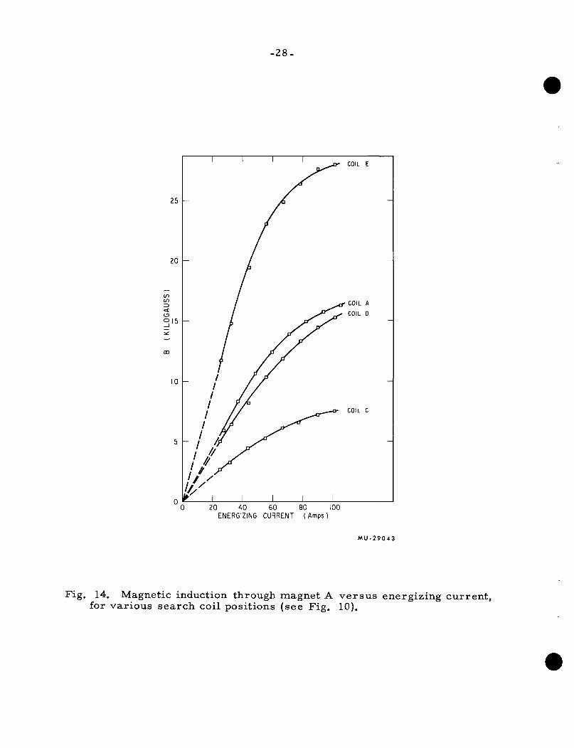
Figures 13-16 summarize the search coil measurements.
It is seen that within the air gap fields of 15 kilogauss are
readily accessible in magnet A, and 10 kilogauss in magnets
B and C. According to Table I, these fields produce trans
verse gradients of about 90 kilogauss/cm for magnet A and 30
kilogauss/cm for magnets B and C. All three magnets are
approaching saturation as the energizing current nears 100
amperes. As indicated in Pigs. 14-16, the saturation appears
to occur close to the pole tips, where the cross-section of
the core necessarily becomes rather small, and thus the
dimensions chosen for the magnet yoke are satisfactory.
The accuracy of the calibration curves, especially for the
air gap region (Pig. 13), is probably not better than +55 ,
However, this is quite sufficient for the applications which
are planned.
Since we may regard the field within the air gap as
defined by the equipotentials and lines of force for the
equivalent two-wire field, the experimentally measured B can
be related to the parameter I in Eqs, (4) and (5). Thus,
although Pigo 13 refers to the midpoint of the search coil
(y=0, z = 1.3a), the field and gradient at any other point within
the air gap are easily obtained by substituting into Eqs. (4)
and (5)
I = 0.106B, for magnet Aj (Ha)
or

•26-
I = 0.212B, for magnets B and C, (Hb)
where the value of B corresponding to the energizing current
used la taken from Pig. 13.

-27-
20
o MAGNET A
A MAGNET B
D MAGNET C
40 50 80 ENERGIZING CURRENT (Amps)
120
M U - 2 9 0 4 2
Fig. 13. Magnetic induction in the a i r gap v e r s u s energizing cur ren t , for magnets A, B, C,
-28.
COIL E
COIL C
20 40 60 80 100 ENERGIZING CURRENT (Amps)
MU-29043
Fig. 14. Magnetic induction through magnet A v e r s u s energizing cur ren t , for var ious search coil positions (see Fig. 10).

-29.
20 40 60 80 ENERGIZING CURRENT (Amps)
100
MU-29044
Fig. 15. Magnetic induction through magnet B ve r sus energizing cur ren t , for var ious sea rch coil positions (see Fig. 10).

-30.
COIL B
20
15
<
S I O — COIL A
ENERGIZING CURRENT ( Amps
M U - 2 9 0 4 5
Fig. 16. Magnetic induction through magnet C v e r s u s energizing cur ren t , for var ious search coil positions (see Fig. 10).

-31-
APPENDIX
Average of Flux Over Coll Area
Other methods '"'•''' of calibrating the field within the
air gap would probably be preferable to that used here if
greater accuracy were required. Nonetheless, it may be worth
while to indicate an improvement that could be made in the
analysis of the search coil measurements. To make this refine
ment significant, it would be necessary to fix the position of
the search coil within the gap more accurately than in our
measurements, but this could be done by means of properly
machined brass spacers.
In deriving Eq. (lO), our main assumptions were (a) that
the lines of magnetic induction crossing the area of the
search coil are all mutually parallel and (b) that the normal
component B is constant over the coil. For a coil located
in the strongly inhomogeneous field of the air gap these assump
tions are clearly much more approximate than for coils about
the iron core. For the air gap Eq. (8) should be replaced by
$ = NAB (12)
where B denotes a suitable average, over the search coil area,
of the variations in direction and magnitude of the induction.
The experimental B obtained in Eq. (lO) and Pig. 13 likewise
should be properly Interpreted as B. The average may be
evaluated from the spatial variation of the two-wire field
prescribed by Eq. (4). The calculation will therefore yield a

relation between I and B which should provide a more accurate
prediction of the air gap field than given by Eq. (ll).
The notation used is shown in Pig. 17. The two-wire
equipotentials constitute a family of circles which all pass
through the points (y=a, z = O) and (y=-a, z = 0). The search
coil is located symmetrically with respect to the plane y=0.
It has negligibly small thickness, width 2b, and lies in the
plane z = a+d, at distance d from the convex pole tip. There
is an equipotential intersecting both of the endpoints of the
coil, (b,a+d) and (-b,a+d). The radius r and origin (0,h)
of this equipotential may be determined from
a2 + h2==r2 (13)
and
\? + (a+d-h)^ = r .
The flux through the search coil is that cutting this circle
between -0 to +0 , where
B^ = arcsin (b/r). (l4)
Furthermore, the flux lines are all normal to the equipotential
surface. Therefore, the total flux through the coil is
$ = / dd) = N / / B(e)dA, (15)
0
-«o
d^ =
0 -9„
where I is the length of the search coil and
B(0) = H(0) = 4al/r^r2
dA = rdSdi.

- 3 3 -
(Q+d,-b)
M U - 2 9 0 4 6
Fig. 17. Definition of coordinates used in averaging flux, over s ea rch coil a r ea .

-34-
Accordingly,
* =
e 4NIar.« /
-e
d0
^1^2 0 - "
(16)
o
and, on comparing Eq. (12), we obtain
I = F(0O)B > (17)
where
9
F(8J = b/(4ar/°j^). (18)
To evaluate the factor F ( 0 ), we require r-. and rg as functions
of e. Prom Pig, 17,
r^ = 2r^(l-cosx) (l9)
r^ = 2r^(l-cosX')
and if we define
Y = arcsin (a/r) (20)
then
X = 7r-Y-0 (21)
X' = 7r-Y+0 ,
In general, Eq,, (l8) must be evaluated numerically. If the
width of the search coil becomes negligible,
P(8„) - ^ ^'^4l^^>' . (22)
and Eq. (l7) reduces to Eq. (ll).
-35-
ACKNOWLEDGMENTS
We wish to thank Carl Baugh for his skilful workmanship
in the fabrication of the magnets. We are also much indebted
to our colleague, John Birely, and to Joseph Dorst, Peter
Watson, and Fred Macondray of the Magnet Testing Group, for
their assistance and advice in the calibrations.

-36-
References
R. G. J. Praser, Molecular Rays (Cambridge University
Press, 1931).
K. P. Smith, Molecular Beams (Methuen Monographs, 1955).
N. P. Ramsey, Molecular Beams (Clarendon Press, Oxford,
1956).
P. Kusch and V. Hughes, Handbuch der Physik, 37 (Springer,
1959).
K. Rubin, J. Perel, and B. Bederson, Phys. Rev. 117, 151
(I960).
K. Berkling, C. Schlier, and P. Toschek, Zeitschrift f.
Physik, 168, 81 (1962).
D. R. Herschbach, Disc. Faraday Soc. 33 (1962).
L. C. Lewis, Zeitschift f. Physik, 69, 786 (l93l).
J. M. Hendrie, J. Chem. Phys. 22, 1503 (l954).
T. A. Milne and P. W. Gilles, J. Am. Chem. Soo. 81^ 6115
(1959).
V. W. Cohen and A. Ellett, Phys. Rev. 51, 65 (1937).
B. Bederson and K. Rubin, AEC Technical Report NYO-10,
117 (New York University, New York, February, 1962).
I. I. Rabi, J. M. B. Kellogg, and J. R. Zacharias, Phys.
Rev. 46, 157 (l934).
Reference 3, pp. 398, 431-432.
Electronic Measurements Company, Red Bank, Eatontown,
New Jersey.
Reference 1, p. 116-117.
R. M. Bozorth, Rev. Mod. Phys. 19, 29 (1947).

This report was prepared as an account of Government sponsored work. Neither the United States, nor the Commission, nor any person acting on behalf of the Commission:
A. Makes any warranty or representation, expressed or implied, with respect to the accuracy, completenes or usefulness of the information contained in this report, or that the use of any information, apparatus, method, or process disclosed in this report may not infringe privately owned rights; or
B. Assumes any liabilities with respect to the use of or for damages resulting from the use of any infor mation, apparatus, method, or process disclosed in this report.
As used in the above, "person acting on behalf of the Commission" includes any employee or contractor of the Commission, or employee of such contractor, to the extent that such employee or contractor of the Commission, or employee of such contractor prepares, disseminates, or provides acce to, any information pursuant to his employment or contract with the Commission, or his employment with such contractor