Embed Size (px)
Citation preview
JOURNAL OF PROPULSION AND POWER
Vol. 22, No. 2, March–April 2006
Erosion and Deposition in Turbomachinery
A. Hamed and W. TabakoffUniversity of Cincinnati, Cincinnati, Ohio 45221
andR. Wenglarz
South Carolina Institute for Energy Studies, Clemson, South Carolina 29634
This paper presents a review of erosion and deposition research in turbomachines and the associated degrada-tion in engine performance caused by particulate matter ingestion. Parameters affecting surface material lossesas a result of erosion and development of experimental and analytical approaches to predict flowpath erosion anddeposition are discussed. Tests results that quantify the effects of temperature, impact particle composition, impactvelocity and angle, and surface material composition are reviewed along with particle restitution data (ratios ofrebound to impact velocities and angles). Development and application of models using these data to calculatesurface erosion in turbomachinery are described. These models predict particle trajectories in turbomachinerypassages to determine impact rates, impact velocities, impact angles and uses the experimentally-obtained erosiondata to calculate material losses. Literature on the effects of erosion on turbomachine performance and life issurveyed. Mechanisms of particle delivery and attachment upon arrival at turbomachine flowpath surfaces arealso discussed along with experiential models that have been developed to predict surface deposit buildup. Deliveryto turbine surfaces can occur as a result of inertial flight, as for erosion, but also through transport mechanismsinvolving turbulence, Brownian diffusion, and thermophoresis. The particle size range, where each of these mech-anisms is dominant for delivery to surfaces, is described. The history and experience of developing models thatuse these mechanisms to quantify particle delivery rates to turbine flow path surfaces is discussed, along withthe use of sticking fraction data to determine the amount of material retained on the surfaces after delivery andthe resulting deposit buildup rates. Finally, factors that control whether extreme rates of deposition can occur inturbomachinery are described.
Introduction
S USPENDED solid particles are often encountered in turboma-chinery operating environment because of several mechanisms
that contribute to particle ingestion in gas turbine engines. Solid
A. Hamed is Department Head and Bradley Jones Professor of Aerospace Engineering & Engineering Mechanics at the University of Cincinnati.Dr. Hamed has thirty years’ research experience in gas turbine erosion, propulsion systems, multi-phase flow, and aeroacoustics. She has authoredover 300 technical publications including journal articles and reports with her students, is editor of the International Journal of Computational FluidDynamics, and Executive Secretary of the International Society for Airbreathing Engines (ISOABE). Dr. Hamed has served as chair of the ASMEFluids Application Systems Committee and the Gas Turbine Education Committee. She is a fellow of both the American Institute of Aeronautics andAstronautics and of the American Society of Mechanical Engineers and a member of the American Society of Engineering Education.
Dr. Widen Tabakoff is currently Professor of aerospace engineering & engineering mechanics and Director of the Turbomachinery Deteriorationand Erosion Laboratory at the University of Cincinnati. He received his M.S. in mechanical engineering in Prague, Czechoslovakia, and continued hiseducation and employment at the University of Berlin in Germany, where he received his M.S. and Dr. Ing. (Ph.D.) degrees in aeronautical engineering.In 1948 Dr. Tabakoff took an air force engineering position in Buenos Aires, Argentina. In 1955 he returned to Germany where he was employed byHoechst AG as Research Director for the design of advanced facilities for chemical products. In 1957 he was contracted by the U.S. Army to workon rockets with Dr. Werner von Braun in Huntsville, AL. In 1958, Dr. Tabakoff moved to Cincinnati to teach at the University of Cincinnati and towork for the U.S. Army Research Laboratory in Mariemont, where he did calculations and materials testing for the Saturn V at Cape Kennedy, FL.Dr. Tabakoff is a recognized expert in the areas of propulsion, two-phase flows, aerodynamic heating, turbomachinery performance, deterioration,and erosion. He has authored over 350 publications and is a Fellow of AIAA and ASME and a Graduate Fellow of the University of Cincinnati. From1958 until now Dr. Tabakoff has had many contracts from the Department of Defense, the Department of Energy, NASA, NSF, and many privateindustries and government laboratories.
Richard Wenglarz received B.S. and M.S degrees from the University of Illinois, and a Ph.D. degree from Stanford University, all in engineer-ing mechanics. He has held positions at the University of Newcastle Upon Tyne, Bellcomm, Bell Laboratories, Westinghouse R&D Center, RollsRoyce/Allison Division of General Motors, and South Carolina Institute for Energy Studies (SCIES) at Clemson University. His early experienceinvolved dynamics and control for gyroscopic systems and manned space stations. Later experience concerned developing and applying analytical andexperimental methods to evaluate deposition, erosion, and corrosion (DEC) in advanced energy systems (e.g., gas turbines and fuel cells) operatingwith alternate fuels. Currently, Dr. Wenglarz is Manager of Research at SCIES for a DOE-sponsored program supporting university gas turbineresearch nationwide. Dr. Wenglarz has over 80 publications and presentations including invited presentations at the Von Karman Institute for FluidDynamics, Yale University, U.K. Central Electricity Research Laboratories, Cambridge University, and the Kentucky Energy Cabinet Laboratories.
Received 27 June 2005; revision received 19 August 2005; accepted for publication 25 August 2005. Copyright c© 2005 by the authors. Published by theAmerican Institute of Aeronautics and Astronautics, Inc., with permission. Copies of this paper may be made for personal or internal use, on condition that thecopier pay the $10.00 per-copy fee to the Copyright Clearance Center, Inc., 222 Rosewood Drive, Danvers, MA 01923; include the code 0748-4658/06 $10.00in correspondence with the CCC.
and molten particles can be produced during the combustion pro-cess from burning heavy oils or synthetic fuels, and aircraft enginescan encounter particles transported by sand storms to several thou-sand feet altitude.1 Thrust reverser efflux at low airplane speeds
350
HAMED, TABAKOFF, AND WENGLARZ 351
Fig. 1 Multistage compressor erosion.
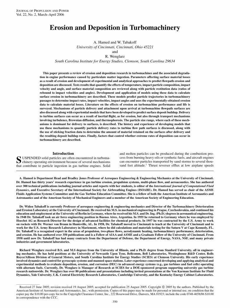
Fig. 2 Effect of flight cycles on compressor blade erosion.
as well as engine inlet to ground vortex during high power settingwith the aircraft standing or moving on the runway can blow sand,dust, ice, and other particles into the engine. Helicopter engines areespecially susceptible to large amounts of dust and sand ingestionduring hover, takeoff, and landing. Dust erosion proved so severeduring the Vietnam field operations that some engines had to beremoved from service after fewer than 100 h of operation.2 Aftertwo decades of technological advances, the loss in power and surgemargins as a result of compressor blade erosion caused some he-licopter units to be removed after fewer than 20 h during the GulfWar field operations.3 A picture of T-53 G compressor after erosiontests conducted with runway sand at the University of Cincinnati isshown in Fig. 1.
The light colors indicate the eroded rotor and stator blade sur-faces. One can see the leading edge and pressure surface erosionalong the first rotor and towards the rotor blade tips and stator bladeroots in subsequent stages. In commercial applications, flight cy-cles determine turbomachinery blade erosion rather than total flighthours (Fig. 2).
Particulate clouds from the eruption of volcanoes present one ofthe most dangerous environments for aircraft engines. Several inci-dents have been related to engine operation in volcanic ash cloud
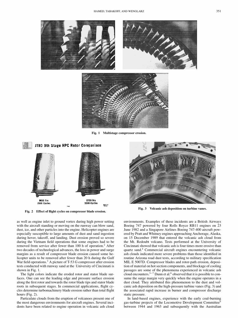
Fig. 3 Volcanic ash deposition on turbine vanes.
environments. Examples of these incidents are a British AirwaysBoeing 747 powered by four Rolls Royce RB11 engines on 23June 1982 and a Singapore Airlines Boeing 747-400 aircraft pow-ered by Pratt and Whitney engines approaching Anchorage, Alaska,on 15 December 1989 that entered the volcanic ash cloud fromthe Mt. Redoubt volcano. Tests performed at the University ofCincinnati showed that volcanic ash is four times more erosive thanquartz sand.4 Commercial aircraft engines encountering volcanicash clouds indicated more severe problems than those identified inroutine Arizona road dust tests, according to military specificationMIL E 5007D. Compressor blades and rotor-path erosion, deposi-tion of material on hot section components, and blockage of coolingpassages are some of the phenomena experienced in volcanic ashcloud encounters.5−7 Dunn et al.8 observed that it is possible to con-sume the surge margin very quickly when the engine operates in adust cloud. They attributed this phenomenon to the dust and vol-canic ash deposition on the high-pressure turbine vanes (Fig. 3) andthe associated rapid increase in burner and compressor dischargestatic pressure.
In land-based engines, experience with the early coal-burninggas-turbine projects of the Locomotive Development Committee9
between 1944 and 1963 and subsequently with the Australian
352 HAMED, TABAKOFF, AND WENGLARZ
coal-burning gas turbine project10 produced a great deal of infor-mation on deposition and erosion. The type of coal used and engineflowpath affected both deposition and erosion, but rotor tip speedhad the greatest impact on erosion. Dussourd11 proposed a simpleone-dimensional model for predicting material loss of turbine bladesas a result of erosion based on adaptation of bluff-body relations forparticle impact velocity and capture. Using existing databases tocalibrate the one constant and the velocity exponent in the derivedequation, Dussourd projected one times blade life improvement witha 50–60% reduction in flow velocity. Debond or spallation of ther-mal barrier coatings is an additional degradation mechanism in air-and ground-based turbines. In a recent surface characterization studyof nearly 100 land-based turbine components, Bons et al.12 foundsurface roughness levels four to eight times greater than the levelfor production line hardware and observed that film cooling sitesare particularly prone to surface degradation. Even small particlesof 1 to 30 μ in size have been known to cause severe damage tothe exposed components of gas turbines.13 The associated degrada-tion of blades and flowpath through erosion and deposition causesincreased losses and heat transfer to surfaces protected by cooling,reduced stability and life, and can even lead to a complete loss ofpower.
This paper presents a review of the experimental and numericalinvestigations of the various aspects associated with particle inges-tion, erosion and deposition in turbomachines, and their effects onperformance. It includes a summary of results, descriptions of testfacilities, and discussion of the methodologies developed for erosionand deposition predictions.
ErosionTurbomachinery erosion is affected by many factors such as the
ingested particle characteristics, gas flowpath, blade geometry, op-erating conditions, and blade material. Both experimental and nu-merical studies were conducted to determine the pattern and inten-sity of compressor and turbine-blade erosion. Grant and Tabakoff14
and Balan and Tabakoff15 conducted experimental studies of single-stage axial-flow compressor erosion. Examination of disassembledrotor blades after sand ingestion revealed blunted leading edges,sharpened trailing edges, reduced blade chords, and increased pres-sure surface roughness. Sugano et al.16 reported similar observationsregarding the changes produced by erosion in axial-induced draftfans of coal-fired boilers. They also determined that blade chordreduction and material removal from the pressure surface increasedwith particle size.
Richardson et al.17 presented results of JT9D high-pressure com-pressor diagnostic study in which they documented the changes inairfoil roughness, blade airfoil, and tip clearance with service. Thestudy indicated that in general the changes correlated well with en-gine cycles not with hours of engine service. Rotor-blade erosionwas observed mainly in the outer 50% of the span, where signif-icant reductions in the blade chord and thickness and changes inthe leading- and trailing-edge geometries were observed. Surfaceroughness measurements indicated quick buildup with no trendsobserved beyond 2000 cycles. Tip clearances increased as a resultof both blade shortening and rubstrip erosion. Dunn et al.18 mea-sured tip clearance that exceeded specifications by a factor of threewith operation in dust-laden environments and reported surge oc-currences when the engine was run in this deteriorated state.
Coating and Blade Material Erosion Studies and FacilitiesTheoretical studies of material loss by solid particle erosion are
predominantly empirical, involving basic assumptions as to the pro-cess governing material removal. Different combinations of cut-ting, fatigue, brittle fracture, and melting mechanisms have beenproposed and supported by experimental data from erosion tests.Experimental studies of particle surface impacts are necessary toprovide blade material erosion and particle rebound characteristicsover the range of impinging conditions encountered in turboma-chines. New blade coating materials are often tested for erosion atspecified temperatures and particle impact velocities and impinge-ment angles. These tests are carried out in facilities that control
particle-laden flow around the target to achieve the desired impactconditions over the tested coupons.
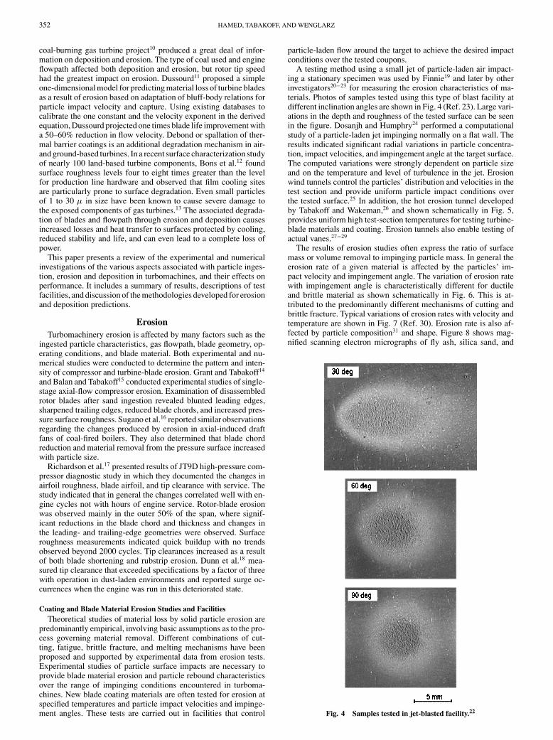
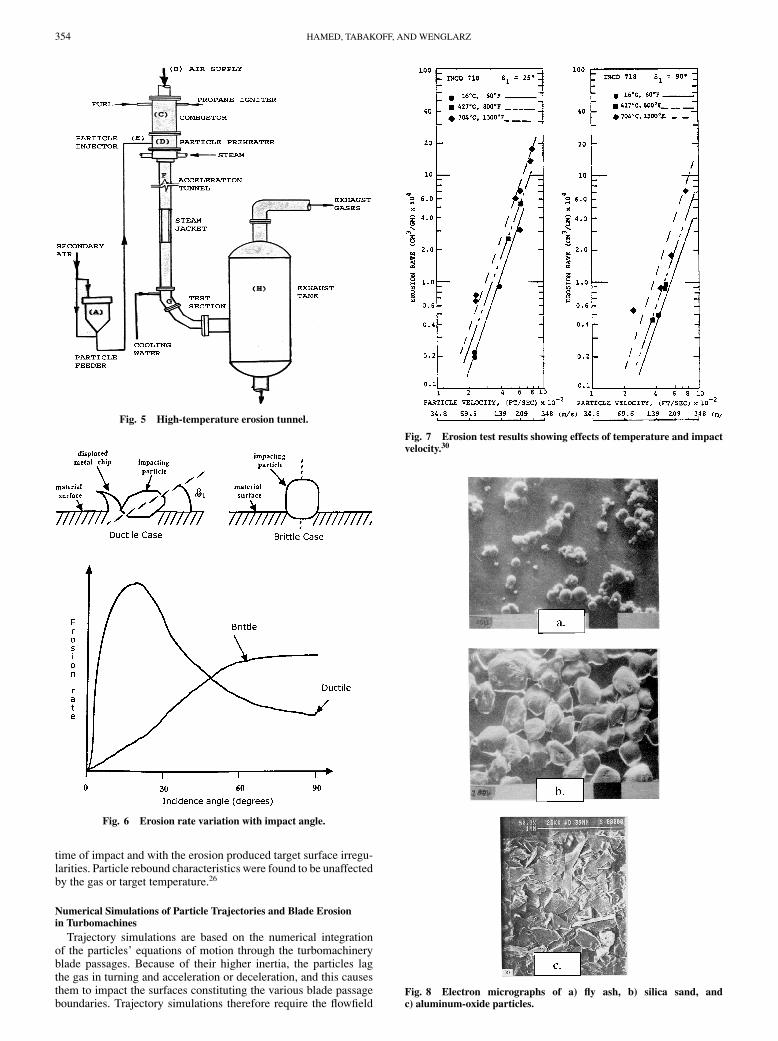
A testing method using a small jet of particle-laden air impact-ing a stationary specimen was used by Finnie19 and later by otherinvestigators20−23 for measuring the erosion characteristics of ma-terials. Photos of samples tested using this type of blast facility atdifferent inclination angles are shown in Fig. 4 (Ref. 23). Large vari-ations in the depth and roughness of the tested surface can be seenin the figure. Dosanjh and Humphry24 performed a computationalstudy of a particle-laden jet impinging normally on a flat wall. Theresults indicated significant radial variations in particle concentra-tion, impact velocities, and impingement angle at the target surface.The computed variations were strongly dependent on particle sizeand on the temperature and level of turbulence in the jet. Erosionwind tunnels control the particles’ distribution and velocities in thetest section and provide uniform particle impact conditions overthe tested surface.25 In addition, the hot erosion tunnel developedby Tabakoff and Wakeman,26 and shown schematically in Fig. 5,provides uniform high test-section temperatures for testing turbine-blade materials and coating. Erosion tunnels also enable testing ofactual vanes.27−29
The results of erosion studies often express the ratio of surfacemass or volume removal to impinging particle mass. In general theerosion rate of a given material is affected by the particles’ im-pact velocity and impingement angle. The variation of erosion ratewith impingement angle is characteristically different for ductileand brittle material as shown schematically in Fig. 6. This is at-tributed to the predominantly different mechanisms of cutting andbrittle fracture. Typical variations of erosion rates with velocity andtemperature are shown in Fig. 7 (Ref. 30). Erosion rate is also af-fected by particle composition31 and shape. Figure 8 shows mag-nified scanning electron micrographs of fly ash, silica sand, and
Fig. 4 Samples tested in jet-blasted facility.22
HAMED, TABAKOFF, AND WENGLARZ 353
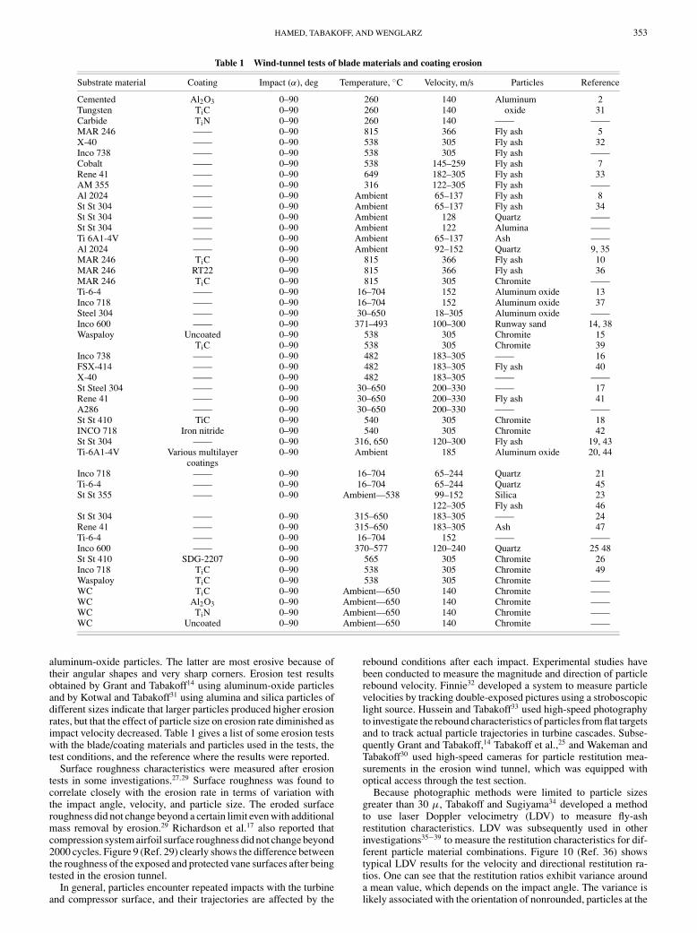
Table 1 Wind-tunnel tests of blade materials and coating erosion
Substrate material Coating Impact (α), deg Temperature, ◦C Velocity, m/s Particles Reference
Cemented Al2O3 0–90 260 140 Aluminum 2Tungsten TiC 0–90 260 140 oxide 31Carbide TiN 0–90 260 140 —— ——MAR 246 —— 0–90 815 366 Fly ash 5X-40 —— 0–90 538 305 Fly ash 32Inco 738 —— 0–90 538 305 Fly ash ——Cobalt —— 0–90 538 145–259 Fly ash 7Rene 41 —— 0–90 649 182–305 Fly ash 33AM 355 —— 0–90 316 122–305 Fly ash ——Al 2024 —— 0–90 Ambient 65–137 Fly ash 8St St 304 —— 0–90 Ambient 65–137 Fly ash 34St St 304 —— 0–90 Ambient 128 Quartz ——St St 304 —— 0–90 Ambient 122 Alumina ——Ti 6A1-4V —— 0–90 Ambient 65–137 Ash ——Al 2024 —— 0–90 Ambient 92–152 Quartz 9, 35MAR 246 TiC 0–90 815 366 Fly ash 10MAR 246 RT22 0–90 815 366 Fly ash 36MAR 246 TiC 0–90 815 305 Chromite ——Ti-6-4 —— 0–90 16–704 152 Aluminum oxide 13Inco 718 —— 0–90 16–704 152 Aluminum oxide 37Steel 304 —— 0–90 30–650 18–305 Aluminum oxide ——Inco 600 —— 0–90 371–493 100–300 Runway sand 14, 38Waspaloy Uncoated 0–90 538 305 Chromite 15
TiC 0–90 538 305 Chromite 39Inco 738 —— 0–90 482 183–305 —— 16FSX-414 —— 0–90 482 183–305 Fly ash 40X-40 —— 0–90 482 183–305 —— ——St Steel 304 —— 0–90 30–650 200–330 —— 17Rene 41 —— 0–90 30–650 200–330 Fly ash 41A286 —— 0–90 30–650 200–330 —— ——St St 410 TiC 0–90 540 305 Chromite 18INCO 718 Iron nitride 0–90 540 305 Chromite 42St St 304 —— 0–90 316, 650 120–300 Fly ash 19, 43Ti-6A1-4V Various multilayer 0–90 Ambient 185 Aluminum oxide 20, 44
coatingsInco 718 —— 0–90 16–704 65–244 Quartz 21Ti-6-4 —— 0–90 16–704 65–244 Quartz 45St St 355 —— 0–90 Ambient—538 99–152 Silica 23
122–305 Fly ash 46St St 304 —— 0–90 315–650 183–305 —— 24Rene 41 —— 0–90 315–650 183–305 Ash 47Ti-6-4 —— 0–90 16–704 152 —— ——Inco 600 —— 0–90 370–577 120–240 Quartz 25 48St St 410 SDG-2207 0–90 565 305 Chromite 26Inco 718 TiC 0–90 538 305 Chromite 49Waspaloy TiC 0–90 538 305 Chromite ——WC TiC 0–90 Ambient—650 140 Chromite ——WC Al2O3 0–90 Ambient—650 140 Chromite ——WC TiN 0–90 Ambient—650 140 Chromite ——WC Uncoated 0–90 Ambient—650 140 Chromite ——
aluminum-oxide particles. The latter are most erosive because oftheir angular shapes and very sharp corners. Erosion test resultsobtained by Grant and Tabakoff14 using aluminum-oxide particlesand by Kotwal and Tabakoff31 using alumina and silica particles ofdifferent sizes indicate that larger particles produced higher erosionrates, but that the effect of particle size on erosion rate diminished asimpact velocity decreased. Table 1 gives a list of some erosion testswith the blade/coating materials and particles used in the tests, thetest conditions, and the reference where the results were reported.
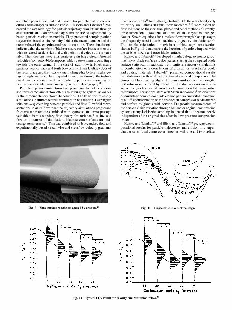
Surface roughness characteristics were measured after erosiontests in some investigations.27,29 Surface roughness was found tocorrelate closely with the erosion rate in terms of variation withthe impact angle, velocity, and particle size. The eroded surfaceroughness did not change beyond a certain limit even with additionalmass removal by erosion.29 Richardson et al.17 also reported thatcompression system airfoil surface roughness did not change beyond2000 cycles. Figure 9 (Ref. 29) clearly shows the difference betweenthe roughness of the exposed and protected vane surfaces after beingtested in the erosion tunnel.
In general, particles encounter repeated impacts with the turbineand compressor surface, and their trajectories are affected by the
rebound conditions after each impact. Experimental studies havebeen conducted to measure the magnitude and direction of particlerebound velocity. Finnie32 developed a system to measure particlevelocities by tracking double-exposed pictures using a stroboscopiclight source. Hussein and Tabakoff33 used high-speed photographyto investigate the rebound characteristics of particles from flat targetsand to track actual particle trajectories in turbine cascades. Subse-quently Grant and Tabakoff,14 Tabakoff et al.,25 and Wakeman andTabakoff30 used high-speed cameras for particle restitution mea-surements in the erosion wind tunnel, which was equipped withoptical access through the test section.
Because photographic methods were limited to particle sizesgreater than 30 μ, Tabakoff and Sugiyama34 developed a methodto use laser Doppler velocimetry (LDV) to measure fly-ashrestitution characteristics. LDV was subsequently used in otherinvestigations35−39 to measure the restitution characteristics for dif-ferent particle material combinations. Figure 10 (Ref. 36) showstypical LDV results for the velocity and directional restitution ra-tios. One can see that the restitution ratios exhibit variance arounda mean value, which depends on the impact angle. The variance islikely associated with the orientation of nonrounded, particles at the
354 HAMED, TABAKOFF, AND WENGLARZ
Fig. 5 High-temperature erosion tunnel.
Fig. 6 Erosion rate variation with impact angle.
time of impact and with the erosion produced target surface irregu-larities. Particle rebound characteristics were found to be unaffectedby the gas or target temperature.26
Numerical Simulations of Particle Trajectories and Blade Erosionin Turbomachines
Trajectory simulations are based on the numerical integrationof the particles’ equations of motion through the turbomachineryblade passages. Because of their higher inertia, the particles lagthe gas in turning and acceleration or deceleration, and this causesthem to impact the surfaces constituting the various blade passageboundaries. Trajectory simulations therefore require the flowfield
Fig. 7 Erosion test results showing effects of temperature and impactvelocity.30
Fig. 8 Electron micrographs of a) fly ash, b) silica sand, andc) aluminum-oxide particles.
HAMED, TABAKOFF, AND WENGLARZ 355
and blade passage as input and a model for particle restitution con-ditions following each surface impact. Hussein and Tabakoff40 pio-neered the methodology for particle trajectory simulations throughaxial turbine and compressor stages and the use of experimentallybased particle restitution models. They presented sample particletrajectories based on the velocity field at the mean diameter and themean value of the experimental restitution ratios. Their simulationsindicated that the number of blade pressure surface impacts increasewith increased particle size and with their initial velocity at the stageinlet. They demonstrated that particles gain large circumferentialvelocities from rotor-blade impacts, which causes them to centrifugetowards the outer casing. In the case of axial-flow turbines, manyparticles bounce back and forth between the blunt leading edges ofthe rotor blade and the nozzle vane trailing edge before finally go-ing through the rotor. The computed trajectories through the turbinenozzle were consistent with their earlier experimental visualizationin a turbine cascade tunnel using high-speed photography.41
Particle trajectory simulations have progressed to include viscousand three-dimensional flow effects following the general advancesin the turbomachinery flowfield solutions. The basis for trajectorysimulations in turbomachines continues to be Eulerian–Lagrangianwith one-way coupling between particles and flow. Flowfield repre-sentations in axial-flow machine trajectory simulations progressedfrom mean streamline combined with spanwise and cross-passagevelocities from secondary-flow theory for turbines42 to inviscidflow on a number of the blade-to-blade stream surfaces for mul-tistage compressors.43 This was combined with secondary flow andexperimentally based streamwise and crossflow velocity gradients
Fig. 9 Vane surface roughness caused by erosion.29
Fig. 10 Typical LDV result for velocity and restitution ratios.36
near the end walls44 for multistage turbines. On the other hand, earlytrajectory simulations in radial-flow machines45,46 were based onflow solutions on the meridinal planes and panel methods. Currently,three-dimensional flowfield solutions of the Reynolds-averagedNavier–Stokes equations for turbulent flow through blade passagesare frequently used in turbomachinery trajectory simulations.29,47
The sample trajectories through in a turbine-stage cross sectionshown in Fig. 11 demonstrate the location of particle impacts withthe turbine nozzle and rotor-blade surface.
Hamed and Tabakoff48 developed a methodology to predict turbo-machinery blade surface erosion patterns using the computed bladesurface statistical impact data from particle trajectory simulationsin combination with correlations of erosion test results for bladeand coating materials. Tabakoff43 presented computational resultsfor blade erosion through a T700 five-stage axial compressor. Thecomputed blade leading edge and pressure-surface erosion along thefirst rotor were followed by rotor-tip and stator root erosion in sub-sequent stages because of particle radial migration following initialrotor impact. This is consistent with Mann and Warnes1 observationsof multistage compressor blade erosion pattern and with Richardsonet al.’s17 documentation of the changes in compressor blade airfoilsand surface roughness with service. Diagnostic measurements ofthe particles’ size variation through helicopter engine1 compressionsystems using isokinetic sampling indicated that it became nearlyindependent of the original size after the low-pressure compressionsystem.
Hamed and Tabakoff48 and Elfeki and Tabakoff45 presented com-putational results for particle trajectories and erosion in a super-charger centrifugal compressor impeller with one and two splitter
Fig. 11 Trajectories in a turbine stage.
356 HAMED, TABAKOFF, AND WENGLARZ
blades, which indicated that particle size strongly influences bothblade erosion pattern and intensity. Blade pressure surfaces’ erosionwere predicted near the casing and increased towards the tip, espe-cially for larger particles. The predictions that were verified in thelab tests of centrifugal compressor erosion64 are consistent with themechanical damage pattern of a number of impeller blades follow-ing helicopter engine dust ingestion reported by Mann and Warnes.1
Beacher and Tabakoff44 performed particle trajectory analysesthrough a multistage coal-fired gas turbine. Although no erosionpredictions were available, the high concentration of particles nearthe casing, past the first rotor, correlated well with the observed lead-ing edge and pressure surface wear pattern reported by Smith et al.9
Metwally et al.49 conducted a computational study to investigatethe effect of blade coating on the erosion of an automotive gas tur-bine. Their blade surface erosion predictions indicated substantialreduction associated with rhodium platinum aluminide (CRT22B)coating compared to the base MAR-M246 alloy blade.
Tabakoff and Hamed’s study50 of simulated particle trajectoriesin radial inflow turbines indicated that the highest erosion rate wasat the rotor pressure surface near the outer corner of the exit. Experi-mental and analytical studies of the performance of aircraft auxiliarypower turbines with silicon-dioxide particle ingestion51 indicated aunique phenomenon in which particles became trapped in the vor-tex region below the nozzles and rotor. This phenomenon, which iscaused by the balance between the radial components of the aero-dynamic drag and the centrifugal forces acting on the particles, wasrecorded on film and showed accumulation and eventual blockingof the flow passage. A large reduction in the wheel speed was mea-sured within a few seconds and continued even after discontinuationof particle ingestion.
The motion of suspended particles through turbomachines is es-sentially a stochastic process because individual particle’s point ofentry into the machine, its initial velocity vector, and its size andshape are all subject to statistical variation. A number of studieswere conducted to investigate the influence of modeling various as-pects of these variances on the computed particle trajectories andblade erosion predictions. Tabakoff et al.52 compared the computedparticle trajectories through a two-stage turbine and the associatedblade erosion for Cincinnati Gas and Electric fly-ash particle sizedistribution to those based on the mean particle diameter. The resultsindicated that nonuniform particle impacts were spread over moreof the blade surface, resulting in lower peak erosion values.
Various methodologies were considered to model the effects ofthe experimentally observed variance in particle rebound character-istics on the erosion of the same two-stage turbine. Initially, Hamed53
used the Fast Probability Integration Method (FPIM) to charac-terize the influence of the measured variance in particle reboundson the particle trajectories through an axial-flow turbine and theassociated blade erosion. The FPI-based model resulted in lowerestimates of both peak and mean blade surface erosion comparedto those computed based on the mean value of the experimentallymeasured restitution ratios. Subsequently, Hamed and Kuhn54 de-veloped stochastic particle trajectory simulations based on directsampling of the actual experimentally measured variance in parti-cle rebound characteristics.30 These results confirmed that the de-terministic bounce model overestimates the blade pressure surfaceerosion. Another important difference was in the stator blade suctionsurface erosion near the trailing edge, which was predicted with thedirect sampling of the experimental rebound statistics, but not withFPI. This phenomenon was found to be associated with particlesreentering the nozzle passage after rebounding from the followingrotor.
Effects of Turbomachinery Erosion on Engine Performance and LifeIn addition to safety considerations, the damage resulting from
turbomachinery erosion has serious consequences from both engi-neering and economic standpoints. According to Kleinert,55 erosionis the primary cause for fuel consumption increase in modern tur-bofan engines. Measurements of isolated compressor and cascadeperformance following erosion cycles14 indicated reduction in com-pressor adiabatic efficiency and stage loading and an increase in
cascade total pressure losses. Blade loading reduction, which wasnoticeable in the outer 50% of the rotor span, increased with erosioncycles as more erosive silica particles passed through the compres-sor. Sugano et al.16 presented the measured change in axial-induceddraft fan performance with the laps of running time in a coal ashenvironment. The most significant effect was the drop in stall pointby 5% when the eroded blade chord reduction reached 10%. Similarlowering of the surge limit in eroded fans was reported by Ghenaietet al.,47 who also characterized the increased tip clearance and mea-sured the drop in efficiency caused by sand erosion of a single-stageventilation fan with C4 rotor blades made from cast aluminum.
Tabakoff and Simpson56 recently conducted an exhaustive ex-perimental study of the erosion characteristics of various compres-sors and turbine-blade materials and coatings. In addition to erosionweight loss, they characterized the corresponding change in chordand thickness of compressor cascades with and without coatings.Subsequently Kline and Simpson28 conducted a full engine sandingestion test demonstration of a T64 RB01 “rainbow” compressorwith alternate bare and coated blades. After ingestion of 35 kg ofsand, they reported 25% loss in horsepower and had to stop the en-gine caused by surging. They confirmed the cascade erosion results56
and determined that virtually 100% of the engine performance losswas attributable to erosion of the bare blades. Edwards and Rouse57
explained how the gas generator power and surge margins are af-fected by the eroded compressor performance both through the dropin surge line caused by erosion and through the rise in operating linecaused by the increased turbine inlet temperature required to main-tain the power level with the loss in compressor efficiency. They alsodiscussed how turbine efficiency loss as a result of erosion reducesgas generator efficiency and requires operation at yet increased tem-peratures, which also causes the operating line to rise above normaland contributes to the reduction in surge margin.
Schmucker and Schaffer58 conducted an experimental study to de-termine the effects of reworked blades for the most common defectsassociated with erosion on axial compressor performance, namely,damaged leading and trailing edges, rounded tips, and rubbed coat-ings. The tests of a high-pressure five-stage research compressorwere done with reworked leading- and trailing-edge blades mixedwith new blades, with 1.5-mm tip rounded rotor blades at the lead-ing and trailing edges and with 1–3% equivalent radial tip clearance.The largest losses in surge margin and in efficiency (7.5 and 2%,respectively) were associated with a 1% increase in tip clearance.The rounded tip rotor blades resulted in 4% loss in surge marginand 0.4% loss in efficiency. The losses in performance for reworkedblades were 2% in surge margin and less than 0.5% in efficiencyand mass flow rate.
Several investigators developed models to simulate the effectsof various aspects of the increased tip clearance and changes incompressor blade airfoils shapes and surface roughness on perfor-mance. Richardson et al.17 developed a model for the associatedhigh-pressure compressor performance deterioration based on mea-surements of in-service engine parts. They reported data on eachstage tip clearance change caused by blade and flowpath erosionand on rotor airfoil changes at six radial locations for each stage.They used the data in a performance model to estimate the lossin efficiency and flow capacity associated with changes tip clear-ance and in airfoil leading- and trailing-edge angles, chord, andthickness. Their estimates of compressor efficiency loss and enginethrust-specific fuel consumption (TSFC) rise agreed with fleet pre-repair engine performance average above 1500 cycles. The authorsalso reported that cold-section refurbishment through restoration oftip clearances, cleaning of airfoils, and replacement of those withchord lengths out of a recommended limit were credited with 1.3%restoration in TSFC. Batcho et al.59 developed a model for compres-sor stage performance deterioration that incorporated tip clearanceand secondary flow loss models and thin airfoil theory lift and dragchanges associated with airfoil mean camberline. They used themodel to examine the response of an eroded compressor and esti-mated 51% reduction in surge margins and 45% in surge pressureratio with compressor erosion. Tabakoff et al.60 and Hamed et al.61
developed a stage-stacking model for the loss in performance caused
HAMED, TABAKOFF, AND WENGLARZ 357
by compressor erosion, which was validated using the single-stagedata of Balan and Tabakoff.15 Subsequently Tabakoff et al.62 usedthe same analysis combined with a thermodynamic model to studythe restoration of performance through water injection.
Nagy et al.63 developed erosion-resistant coating life model andapplied it to coated compressor blade erosion by quartz particles.The life model, which is based on 1.8% reduction in the chord length,was used to calculate the mass of erodent for coated airfoils’ lifefor various coating thicknesses. Naik et al.64 presented the resultsof a detailed investigation on the erosion resistance and durabil-ity of polymer matrix composite coating on Rolls-Royce AE 3007bypass vanes. The rainbow (coated/uncoated) vane erosion tests inthe erosion tunnel demonstrated two to eight times improvementrelative to the bare metal under conditions simulating 5000 flighthours. In addition both structural laboratory vibratory tests and en-gine durability tests demonstrated the capabilities of the coatingsfor propulsion applications.
DepositionSimulation of Particle Delivery to Turbine SurfacesMechanisms of Deposition
There are two types of mechanisms involved in turbine depositionand effects on performance: delivery of impurities to turbine sur-faces and attachment (sticking) of impurities delivered to surfaces.
Mechanisms of DeliveryImpurities from inlet air or fuel can enter the turbine flow passages
as particles (in solid or liquid form) and, often for the hot section,as gaseous species that had been vaporized in upstream combustionor gasification processes. Vaporized impurities that enter the hotsection can condense as liquids on cooled turbine surfaces or in thegas stream as the temperature and pressure drop through the turbinestages. Dominant mechanisms of delivery of particles to turbineflowpath surfaces are inertial impaction, turbulent diffusion/eddyimpaction, Brownian diffusion, and thermophoresis.
For inertial impaction, the particles have sufficient mass to de-viate from turning gas flow streamlines, penetrate airfoil boundarylayers, and essentially crash onto airfoil surfaces. Smaller particlescan be entrained in turbulent eddies in the surface boundary layersto be swept toward airfoils and end walls (turbulent diffusion). Eventhough eddies dissipate near surfaces, the particles have sufficientinertia to coast to the surfaces (eddy impaction). Yet smaller par-ticles with insufficient mass to be delivered by inertial effects canbe transported to surfaces by impacts with the thermally agitatedgas molecules in surface boundary layers. For extremely small par-ticles, the random impacts can produce “random walk” Browniandiffusion delivery to the surfaces. If the surface is cooled (as forairfoils of upstream hot section stages), the energy of the randomimpacts on particles from thermally agitated gas molecules in thethermal boundary layer is higher at the hot side of the particle far-ther from the cooled surface than the cooler side of the particle.This produces a net average impact force from gas molecules in thedirection toward the surface that transports these particles to cooledcomponents (thermophoresis).
Models for Particle Delivery to Turbine SurfacesPerhaps the earliest work65 that applied existing theories of par-
ticle transport to turbines conducted analyses to predict depositionon airfoils as a result of inertial impaction, vapor diffusion, andBrownian diffusion. The inertial impaction relations used by Smithresulted from prior work by Taylor,66 who had studied the impinge-ment of water droplets on aircraft wings. In these and subsequentanalyses of inertial impaction deposition in turbines, Newtonianequations of motion for particles subject to drag forces from thefluid were integrated, and their trajectories and impact rates onairfoil surfaces were calculated. McCreath67 integrated equationsof motion for 15-micron particles in Tyne turbine stator vane androtor-blade passages and found reasonable agreement with deposi-tion buildup measured over their pressure surfaces in experiments.Dring et al.68 showed excellent agreement between calculated tra-
jectories and photographs of trajectories over a range of particlediameters (Stokes numbers from ∼0.1 to 1.9) for experiments us-ing a symmetric airfoil. At turbine flowpath conditions, integrationof particle equations of motion considering only fluid drag forcestypically applies to particles larger than a few microns in diame-ter (Stokes number on the order of 1 or larger), for which particleshave sufficient inertia so that the other mechanisms already de-scribed have a relatively small effect on transport to airfoil nose andpressure (concave) surfaces. Convex (suction) airfoil surfaces areshielded from direct inertial impaction of larger particles so that theother mechanisms just described cause deposition on those surfacesfrom particles smaller than a few microns in diameter.
Developments in theory of particle transport and deposition forsmall particles (Stokes number � 1) that provided the basis for laterapplications to turbines include the work of Lin et al.,69 Friedlanderand Johnstone,70 Davies,71 and Cleaver and Yates.72 The develop-ments of Lin et al. were used by Parker and Lee73 in studies ofdeposition of submicron particles on turbine blades. Friedlanderand Johnstone indicated that, for particles on the order of a micronin diameter, existing Brownian and turbulent theories under pre-dicted deposition measured on surfaces in experiments, and theyproposed that particle transport in that size range near to surfaces isassociated with inertial flight to surfaces (eddy impaction) resultingfrom velocity imparted to particles by turbulent eddies. Davies de-veloped a relation for stopping distance from the surface for whichtransport is dominated by inertial flight. Moore and Crane74 incorpo-rated Davies’ stopping distance relations in their diffusion analysesof particle transport to turbine blades related to corrosion. They alsocalculated inertial impaction delivery to turbine airfoils for particlesin the diameter range from 1 to 10 μ. Hidy and Heisler75 published asurvey of the state of the art of small particle transport and depositionin the late 1970s.
Application of Particle Delivery Models to Turbine DepositionIn the late 1970s to mid-1980s, Rosner and associates76,77 pub-
lished extensively on the theories of condensation, turbulent diffu-sion, and thermophoretic transport of particles in boundary layers.Much of this research was directed to delivery of corrosive com-pounds from turbine flowpaths to bounding surfaces (e.g., airfoils).Menguturk and Sverdrup78 incorporated previous particle deliverytheory advancements for the mechanisms of turbulent and Browniandiffusion into a turbine deposition model and showed the modelpredicted deposition rates that agreed reasonably well with experi-mental deposition data for pipes and a turbine cascade. Wenglarz79
used this model to calculate deposition rates in a 50-MW coal-firedpressurized fluidized bed combustion turbine for alternate particu-late cleanup systems. An approach was also developed to estimateturbine power drops as a result of blockage of the stator passagethroats (minimum flow area in the expander) and maintenance in-tervals for deposit removal to restore power. Other later examplesof applying particle delivery models to predict turbine depositionare given by Ahluwalia et al.80 and Frackrell et al.81 Ahluwaliaet al. combined several mechanistic models for particle and vaportransport to include the simultaneous contributions of Brownianand turbulent diffusion, thermophoresis, eddy impaction, and iner-tial impaction. Predicted deposition using the models agreed wellwith deposition measured in pipe flow and reasonably well withmeasured deposition in a turbine cascade. Particle delivery rateswere then calculated on the surfaces of the first-stage stator vaneof a large turbine. Frackrell et al. reviewed particle delivery mod-eling approaches for application to turbines and compared modelpredictions against experimental deposition data for pipe flow andflow around cylinders, including a probe exposed to deposition ina rig representing combustion products from a coal gasificationsystem.
Calculated deposition profiles using an inertial impaction modelfor particle sizes of about 5 and 15 μ were shown to agree well withdeposition measured on the first-stage vanes and blades in a low-speed, two-stage model turbine. Deposition rates over the concaveand convex surfaces of the first-stage stator vane of a large utilityturbine were then calculated for two ranges of particle sizes.
358 HAMED, TABAKOFF, AND WENGLARZ
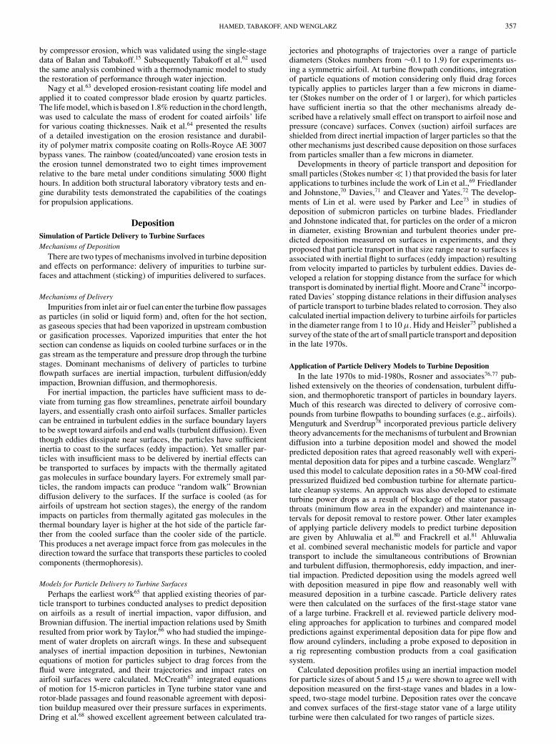
Fig. 12 Turbine vane deposition vs particle diameter.
In the 1990s, natural gas became the fuel of choice for land-basedturbines, and most of the attention shifted away from alternate tur-bine fuels along with concerns about resulting turbine flow pathdegradation. By the turn of the century, little research and devel-opment was directed to turbine deposition. An exception has beenwork in Europe by El-Batsh and Haselbacher described in a numberof publications. For example, these authors published evaluationsand verification of particle delivery models for applications to tur-bines in 2000 (Ref. 82) and calculation of turbine cascade depositioneffects in 2002 (Ref. 83).
Relative Rates of Delivery for MechanismsFigure 12 illustrates the effect of particle diameter on deposi-
tion velocities (deposition rates normalized to gas stream particleconcentration) as calculated by a particle delivery model for the con-cave (pressure) surface trailing edge of the first stator vanes in a largeutility turbine. Turbulent diffusion dominates at the smaller diam-eters shown on the plot. For increasing diameters, eddy impactionenhances turbulent diffusion for surface delivery, and then inertialimpaction dominates for particles larger than a few microns in di-ameter. The deposition velocity curve starts to flatten at diameters inthe vicinity of 0.1 micron as a result of the effects of Brownian dif-fusion at smaller sizes. Because Brownian diffusion rates increasewith decreasing particle diameter, this results in a minimum in thedeposition velocity curve at a small diameter below 0.01 μ that isnot shown on the plot. Although the model used did not includethermophoresis, the depth of the minimum would depend on thedegree of airfoil surface cooling and corresponding magnitude ofthermophoric effects.
Buildup of Impurities Delivered to Turbine SurfacesBecause of the high mass flow rates for gas turbines, the preced-
ing mechanisms are sufficient to cause significant mass delivery ofimpurities to turbine surfaces, even for minute concentrations (e.g.,<1 ppmw) of impurities in the flow stream. For example, a largeturbine with mass flow of 1000 lb/s experiences more than 28,000 lbof impurities in an 8000-h operating year for a flowpath particulateconcentration of 1 ppmw.
Although significant quantities of impurities can be delivered bythe preceding mechanisms to turbine passage airfoils and end walls,whether or not excessive deposition occurs depends on whether ornot there is attachment or sticking of the impurities upon arrival atthose surfaces. Competing mechanisms of attachment and removalare described by Tabakoff et al.84 and are not discussed in detailhere. However, one of the main conclusions was that molten phasesneed to be delivered to the turbine surfaces to sufficiently attach par-ticles so they are not removed and re-entrained in the flow stream.
A small molten mass fraction (a few percent and sometimes less) oftotal material delivered to the surfaces can result in excessive ratesof deposition and strong deposits. A review of past test results fora number of alternate fuels by Wenglarz and Wright85 showed afuel-ash-dependent transition temperature above which deposition(and corrosion) increase drastically along with the characteristicsof these degradations (e.g., an increase in gas temperature of 200◦Fcan increase deposition rates by two orders of magnitude86). Belowthe transition temperature, the main contributor to molten phasesis vaporized ash species that condense in a small diameter range(∼0.01 μ). Above the transition temperature, larger particles in the1-μ and larger diameter range are molten. As illustrated in Fig. 12,delivery rates to turbine surfaces for the micron diameter range aremuch higher that rates for the 0.01-μ range so that much greaterlevels of molten phases can be delivered to turbine surfaces for gasstream temperatures above the transition temperature. Accordingly,Wenglarz and Wright concluded that the most important factor de-termining the level of molten phases delivered to turbine hot-sectionsurfaces and whether there are extreme rates of deposition is prob-ably the gas stream temperature relative to the melting point of theflowpath impurities in the larger particle diameter range.
SummaryA review is given of the experimental and analytical studies
of erosion and deposition in turbomachines by ingested particlesand the associated performance loss. Experimental investigationsof particle-surface interactions in special tunnels that control parti-cle impact conditions provide blade and coating material erosion andparticle restitution characteristics. Numerical simulations of partialdynamics through the blade passage provide the particle deliveryconditions on passage surfaces. Turbomachinery erosion and depo-sition predictions combine the computed surface-interaction statis-tics with experimentally and theoretically based erosion/depositionmodels. In compressors, erosion increases tip clearance, shortensblade chords, increases pressure surface roughness, blunts the lead-ing edge, and sharpens the trailing edge. Particles centrifuge aftertheir first rotor impact, which limits erosion damage to the outer re-gions in subsequent stages. The increased tip clearances and changesin airfoil shapes cause by erosion to turbomachinery causes perfor-mance deterioration. In turbines, inertial impact at high velocitiesof particles larger than a few microns in diameter on airfoil leadingedges and pressure surfaces can cause erosion or deposition depend-ing on the balance of hard versus molten particles. Deposition ofsmaller particles on airfoil suction surfaces is associated with turbu-lent diffusion/eddy impact. Deposition is expected to become moreimportant in the first stage of turbine hot sections as turbine inlettemperatures increase due to the higher fractions of molten particles.Increased fuel consumption, decreased efficiency, flow capacity, andreduced power and surge margins have been attributed to fan andcompressor erosion.
References1Mann, D. L., and Wares, G. D., “Future Direction in Helicopter En-
gine Protection System Configuration,” AGARD-CP-588, Paper No. 4,March 1994.
2Mund, M. G., and Guhna, H., “Gas Turbine Dust Air Cleaners,” Ameri-can Society of Mechanical Engineers, Paper 70-GT-104, Aug. 1970.
3Sirs, R. C., “The Operation of Gas Turbine Engines in Hot & SandyConditions-Royal Air Force Experiences in the Gulf War,” AGARD-CP-558, Paper No. 2, May 1994.
4Tabakoff, W., “Review of Material Erosion Exposed to AerodynamicConditions,” U.S. Dept. of Engineering, Rept. on Program Review, OakRidge, TN, April 1986.
5Mitchell, H. J., and Gilmore, F. R., “Dust-Cloud Effects on Aircraft En-gines: Emerging Issues and New Damage Mechanisms,” RDA-TR-120012-001, Research/Development Associates, Palo Alto, CA, March 1982.
6Chambers, J. C., “The 1982 Encounter of British Airways 747 with theMt. Galuggung Eruption Cloud,” AIAA Paper 85-0097, 1985.
7Smith, W. S., “International Efforts to Avoid Volcanic Ash Clouds,”AIAA Paper 85-0101, 1985.
8Dunn, M. G., Baran, A. J., and Miatah, J., “Operation of Gas Turbine En-gines in Volcanic Ash Clouds,” American Society of Mechanical Engineers,94-GT-170, June 1994.
HAMED, TABAKOFF, AND WENGLARZ 359
9Smith, J., Cargill, R. W., Strimbeck, D. C., Nabors, W. M., and McGee,J. P., “Bureau of Mines Coal-Fired Gas Turbine Research Project: Test ofNew Turbine Blade Design,” RI 6920, U.S. Dept. of the Interior, Bureau ofMines, Washington, DC, 1967.
10Atkin, M. L., and Duke, G. A., “The Operation of a Modified RustonHornsby Gas Turbine on N.S.W. Bituminous Coal,” Aeronautical ResearchLab. Dept. of Supply, Australian Defense Scientific Service, Rept. 133,Aug. 1971.
11Dussourd, J. L., “A Simple One-Dimensional Model for Primary Tur-bine Blade Erosion Prediction,” American Society of Mechanical Engineers,Paper 83-GT-164, June 1983.
12Bons, J. P., Taylor, R. P., McClain, S. T., and Rivir, R. B., “The ManyFacets of Turbine Surface Roughness,” American Society of MechanicalEngineers, 2001-GT-0163, June 2001.
13MacCay, R., “The Gas Turbine as a Source of Continuous PrecisePower,” American Society of Mechanical Engineers, Paper 69-GT-20,May 1969.
14Grant, G., and Tabakoff, W., “Erosion Prediction in TurbomachineryResulting from Environmental Particles,” Journal of Aircraft, Vol. 12, No. 5,1975, pp. 471–478.
15Balan, C., and Tabakoff, W., “Axial Compressor Performance Deterio-ration,” AIAA Paper 84-1208, June 1984.
16Sugano, H., Yamaguchi, N., and Taguchi, S., “A Study on the AshErosion of Axial Induced Draft Fans of Coal-Fired Boilers,” TR, Vol. 19,Mitsubishi Heavy Industries, Tokyo, Japan, Feb. 1982.
17Richardson, J. H., Sallee, G. P., and Smakula, F. K., “Causes ofHigh Pressure Compressor Deterioration in Service,” AIAA Paper 79-1234,June 1979.
18Dunn, M. G., Padova, C., Moller, J. G., and Adams, R. M., “PerformanceDeterioration of a Turbofan and a Turbojet Engine upon Exposure to DustEnvironment,” Journal of Engineering for Gas Turbine and Power, Vol. 109,No. 2, 1987, pp. 336–343.
19Finnie, I., “Erosion of Surfaces by Solid Particles,” Wear, Vol. 3, No. 1,1960, pp. 87–103.
20Sheldon, G. L., “Similarities and Differences in the Erosion Behavior ofMaterials,” Journal of Basic Engineering, Vol. 89, No. 3, 1970, pp. 619–625.
21Tilly, G. P., “A Two Stage Mechanism of Ductile Erosion,” Wear, Vol. 23,No. 2, 1973, pp. 87–93.
22Hutchings, W. H., “A Model for the Erosion of Metals by SphericalParticles at Normal Incidence,” Wear, Vol. 34, No. 2, 1983, pp. 269–281.
23Oka, Y. I., Nishimura, M., Nagahashi, K., and Matsumura, M., “Controland Evaluation of Particle Impact Conditions in a Sand Erosion Test Facility,”Wear, Vol. 250, No. 2, 2001, pp. 736–743.
24Dosanjh, S., and Humphry, J. A., “The Influence of Turbulence onErosion by a Particle-Laden Fluid Jet,” Wear, Vol. 102, Nos. 1–12, 1985,pp. 309–329.
25Tabakoff, W., Grant, G., and Ball, R., “An Experimental Investigation ofCertain Aerodynamic Effects on Erosion,” AIAA Paper 74-639, July 1974.
26Tabakoff, W., and Wakeman, T., “Test Facility for Material Erosionat High Temperature,” American Society for Testing and Materials SpecialPublication 664, West Conshohocken, PA, 1979, pp. 123–135.
27Balan, C., and Tabakoff, W., “A Method for Predicting the PerformanceDeterioration of a Compressor Cascade Due to Sand Erosion,” AIAA Paper84-1208, June 1984.
28Kline, M., and Simpson, G., “The Development of Innovative Methodsfor Erosion Testing a Russian Coating on GE T64 Gas Turbine EngineCompressor Blades,” American Society of Mechanical Engineers, PaperGT2004-54336, June 2004.
29Hamed, A., Tabakoff, W., Rivir, R. B., Das, K., and Arora, P., “Tur-bine Blade Surface Deterioration by Erosion,” Paper No. ASME-IGTI 2004-54328, June 2004.
30Wakeman, T., and Tabakoff, W., “Measured Particle Rebound Charac-teristics Useful for Erosion Prediction,” American Society of MechanicalEngineers, Paper 82-GT-170, June 1982.
31Kotwal, R., and Tabakoff, W., “A New Approach for Erosion Predic-tion due to Fly Ash,” Journal of Engineering for Power, Vol. 103, 1981,pp. 265–270.
32Finnie, I., “An Experimental Study on Erosion,” Proceedings of theSociety for Experimental Stress Analysis, Vol. 17, No. 2, 1960, pp. 65–70.
33Hussein, M. F., and Tabakoff, W., “Dynamic Behavior of Solid ParticlesSuspended by Polluted Flow in Turbine Stage,” Journal of Aircraft, Vol. 10,No. 7, 1973, pp. 334–340.
34Tabakoff, W., and Sugiyama, Y., “Experimental Methods of Determin-ing Particle Restitution Coefficients,” Proceedings of the ASME Symposiumon Polyphase Flow and Transient Technology, American Society of Me-chanical Engineers, New York, Aug. 1980, pp. 203–210.
35Tabakoff, W., Malak, M., and Hamed, A., “Laser Measurements ofSolid-Particle Rebound Parameters Impacting on 2024 Aluminum and6AI-4V Titanium Alloys,” AIAA Journal, Vol. 25, No. 5, 1987, pp. 721–726.
36Tabakoff, W., and Malak, M., “Laser Measurements of Fly Ash ReboundCharacteristics for Use in Trajectory Calculations,” Journal of Turbomachin-ery, Vol. 109, No. 3, 1987, pp. 535–540.
37Tabakoff, W., “Measurements of Particles Rebound Characteristics onMaterials Used in Gas Turbines,” Journal of Propulsion and Power, Vol. 7,No. 5, 1991, pp. 805–813.
38Tabakoff, W., and Hamed, A., “Experimental Investigation of ParticleSurface Interactions for Turomachinery Applications,” Laser AnemometryAdvances and Applications, edited by A. Dybbs and B. Ghorashi, AmericanSociety of Mechanical Engineers, New York, 1991, pp. 775–780.
39Tabakoff, W., Hamed, A., and Murugan, X., “Effect of Target Materialson Particle Restitution Characteristics for Turbomachinery Applications,”Journal of Propulsion and Power, Vol. 12, No. 2, 1996, pp. 260–266.
40Hussein, M. F., and Tabakoff, W., “Computation and Plotting of SolidParticle Flow in Rotating Cascades,” Computers and Fluids, Vol. 2, No. 1,1974, pp. 1–15.
41Tabakoff, W., and Hussein, M. F., “Trajectories of Particles Suspendedin Flows Through Cascades,” Journal of Aircraft, Vol. 8, No. 1, 1971,pp. 60–64.
42Ulke, A., and Roulean, W. T., “The Effects of Secondary Flows onTurbine Blade Erosion,” American Society of Mechanical Engineers, Paper76-GT-74, March 1976.
43Tabakoff, W., “Compressor Erosion and Performance Deterioration,”Journal of Fluids Engineering, Vol. 109, No. 2, 1987, pp. 297–306.
44Beacher, B., and Tabakoff, W., “Trajectories of Ash Particles Througha Coal-Burning Gas Turbine,” American Society of Mechanical Engineers,Paper 84-GT-122, 1984.
45Elfeki, S., and Tabakoff, W., “Erosion Study of Radial Flow Compressorwith Splitters,” American Society of Mechanical Engineers, Paper 86-GT-240, June 1986.
46Tabakoff, W., and Hamed, A., “Effect of Environmental Particles on aRadial Compressor,” AIAA Paper 88-0366, Jan. 1988.
47Ghenaiet, A., Elder, R. L., and Tan, S. C., “Particle Trajectories Throughan Axial Fan and Performance Degradation due to Sand Ingestion,” Ameri-can Society of Mechanical Engineers, Paper 2001-GT-0497, June 2001.
48Hamed, A., and Tabakoff, W., “Experimental and Numerical Simula-tions of the Effects of Ingested Particles in Gas Turbine Engines,” Erosion,Corrosion and Foreign Object Effects in Gas Turbines, Von Karman Inst.,Brussels, 1994.
49Metwally, M., Tabakoff, W., and Hamed, A., “Blade Erosion in Auto-motive Gas Turbine Engine,” Journal of Engineering for Gas Turbines andPower, Vol. 117, Jan. 1995, pp. 213–219.
50Tabakoff, W., and Hamed, A., “Temperature Effect on Particle Dynam-ics and Erosion in Radial Inflow Turbines,” Journal of Turbomachinery,Vol. 110, April 1988, pp. 258–246.
51Clevenger, W., and Tabakoff, W., “Dust Particle Trajectories in AircraftRadial Turbine,” Journal of Aircraft, Vol. 13, No. 10, 1976, pp. 786–791.
52Tabakoff, W., Hamed, A., and Metwally, M., “Effect of Particle Size Dis-tribution on Particle Dynamics and Blade Erosion in Axial Flow Turbines,”Journal of Gas Turbine and Power, Vol. 113, Oct. 1991, pp. 607–615.
53Hamed, A., “An Investigation in the Variance in Particle Surface Inter-actions and Their Effects in Gas Turbines,” Journal of Engineering for GasTurbine and Power, Vol. 114, April 1992, pp. 235–241.
54Hamed, A., and Kuhn, T. P., “Effects of Variational Particle RestitutionCharacteristics on Turbomachinery Erosion,” Journal of Engineering forGas Turbine and Power, Vol. 117, July 1995, pp. 432–440.
55Kleinert, G., “Turbofan Engine Maintenance for Fuel and HardwareConservation,” Sermatech Review, Vol. 33, 1990, pp. 2, 3.
56Tabakoff, W., and Simpson, G., “Experimental Study of Deteriorationand Retention on Coated and Uncoated Compressor and Turbine Blades,”AIAA Paper 2002-2373, Jan. 2002.
57Edwards, V. R., and Rouse, P. L., “U.S. Army Rotorcraft TurboshaftEngines—Dust Erosion Considerations,” AGARD-CP-558, Paper No. 3,April 1994.
58Schmucker, J., and Schaffer, A., “Performance Deterioration of Ax-ial Compressors due to Blade Defects,” AGARD-CP-558, Paper No. 16,April 1994.
59Batcho, P. F., Moller, J. C., Padova, C., and Dunn, M. G., “Interpreta-tion of Gas Turbine Response due to Dust Ingestion,” Vol. 109, July 1978,pp. 344–352.
60Tabakoff, W., Lakshiminarasimha, A. N., and Pasin, M., “Simulationof Compressor Performance Deterioration due to Erosion,” Journal of Tur-bomachinery, Vol. 112, No. 1, 1990, pp. 78–112.
61Hamed, A., Tabakoff, W., and Singh, D., “Modeling of Compressor Per-formance Deterioration due to Erosion,” International Journal of RotatingMachinery, Vol. 4, No. 4, 1998, pp. 243–248.
62Tabakoff, W., Kaushik, S., and Lakshiminarasimha, A. N., “Perfor-mance Improvement of an Eroded Axial Flow Compressor Using WaterInjection,” AIAA Paper 90-2016, July 1990.
360 HAMED, TABAKOFF, AND WENGLARZ
63Nagy, D. R., Parameswaran, V. R., MacLeod, J. D., and Immarigeon,J. P., “Protective Coatings for Compressor Gas Path Components,” AGARD-CP-558, Paper No. 7, April 1994.
64Naik, S. K., Sutter, J. K., Tabakoff, W., Siefker, R. G., Haller, H. S.,Cupp, R. J., and Miyoshi, K. K., “Wear Resistant Polymer Matrix Compos-ites for Aerospace Applications,” American Society of Mechanical Engi-neers, Paper GT2004-54330, June 2004.
65Smith, H. C. G., “A Theoretical Note upon the Mechanism of Depo-sition in Turbine Airfoil Fouling,” Memo. M.145, National Gas TurbineEstablishment, Pyestock-in-Farnborough, Hants, England, UK, Feb. 1952.
66Taylor, G. I., “Notes on Possible Equipment and Technique for Ex-periments on Icing on Aircraft,” R.M. 2024, British Aeronautical ResearchCouncil, London, England, UK, Jan. 1940.
67McCreath, C. G., “The Role of Salt Particulate Matter in the Hot Cor-rosion Phenomenon Exhibited by Gas Turbine Power Plants Operated in aMarine Environment,” Power Industry Research, Vol. 2, 1982, pp. 1–15.
68Dring, R. P., Casper, J. R., and Suo, M., “Particle Trajectories in TurbineCascades,” Journal of Energy, Vol. 3, No. 3, 1979, pp. 161–166.
69Lin, C. S., Moulton, R. W., and Putnam, G. L., “Mass Transfer Be-tween Solid Walls and Fluid Streams,” Industrial and Engineering Chem-istry, Vol. 45, No. 1, 1953, pp. 636–640.
70Friedlander, S. K., and Johnstone, H. F., “Deposition of Suspended Par-ticles from Turbulent Gas Streams,” Industrial and Engineering Chemistry,Vol. 49, No. 7, 1957, pp. 1151–1156.
71Davies, C. N., “Deposition from Moving Aerosols,” Aerosol Science,Academic Press, New York, 1966.
72Cleaver, J. W., and Yates, B., “A Sub Layer Model for Deposition ofParticles from a Turbulent Flow,” Chemical Engineering Science, Vol. 30,1975, pp. 983–992.
73Parker, G. J., and Lee, P., “Studies of the Deposition of SubmicronParticles on Turbine Blades,” Proceedings of the Institute of MechanicalEngineers, Vol. 186, No. 38, 1972, pp. 519–526.
74Moore, M. J., and Crane, R. I., “Aerodynamic Aspects of Gas TurbineBlade Corrosion,” Deposition and Corrosion in Gas Turbines, edited byA. Hart and A. Cutler, Wiley, New York, 1973, pp. 35–57.
75Hidy, G. M., and Heisler, S. L., “Transport and Deposition of FlowingAerosols,” Recent Developments in Aerosol Science, edited by D. T. Shaw,Wiley, New York, 1978, pp. 135–165.
76Rosner, D. E., Chen, G. C., Fryburg, G. C., and Kohl, F. J., “ChemicallyFrozen Multicomponent Boundary Theory of Salt and/or Ash DepositionRates for Combustion Gases,” Combustion Science and Technology, Vol. 20,1979, pp. 87–106.
77Rosner, D. E., and Fernandez de la Mora, J., “Particle Transport AcrossTurbulent Non-Isothermal Boundary Layers,” Journal of Engineering forPower, Vol. 104, No. 4, 1982, pp. 885–994.
78Menguturk, M., and Sverdrup, E. F., “A Theory for Fine Particle De-position in 2-D Boundary Layer Flows and Application to Gas Turbines,”American Society of Mechanical Engineers, Paper 81-GT-54, March 1981.
79Wenglarz, R. A., “An Assessment of Deposition in PFBC Power PlantGas Turbines,” Journal of Engineering for Power, Vol. 103, No. 3, 1981,pp. 552–560.
80Ahluwalia, R. K., Im, K. H., Chuang, C. F., and Hajduk, J. C., “Particleand Vapor Deposition in Coal-Fired Gas Turbines,” American Society ofMechanical Engineers, Paper 86-GT-239, June 1986.
81Frackrell, J., Brown, K., and Young, J., “Modelling Particle Depositionin Gas Turbines Employed in Advanced Coal-Fired Systems,” AmericanSociety of Mechanical Engineers, Paper 94-GT-467, June 1994.
82El-Batsh, H., and Haselbacher, H., “Effect of Turbulence Modelingon Particle Dispersion and Deposition on Compressor and Turbine BladeSurfaces,” American Society of Mechanical Engineers, Paper 2000-GT-519,May 2000.
83El-Batsh, H., and Haselbacher, H., “Numerical Investigation of the Ef-fect of Ash Particle Deposition on the Flow Field Through Turbine Cas-cades,” American Society of Mechanical Engineers, Paper GT-2002-30600,June 2002.
84Tabakoff, W., Hamed, A., and Wenglarz, R., Particulate Flows andBlade Erosion, Lecture Series Publ., von Karman Inst. for Fluid Dynamics,Rhode-Saint-Genese, Belgium, No. 2, 1988, pp. 34–40.
85Wenglarz, R. A., and Wright, I. G., “Alternate Fuels for Land-BasedTurbines,” Materials and Practices to Improve Resistance to Fuel DerivedEnvironmental Damage in Land- and Sea-Based Turbines, Rept. 1009173,EPRI, Palo Alto, CA and Colorado School of Mines, Golden, CO, Oct. 2003,pp. 4-45–4-64.
86Wenglarz, R. A., and Fox, R. G., “Physical Aspects of Deposition fromCoal-Water Fuels Under Gas Turbine Conditions,” Journal of Engineeringfor Gas Turbines and Power, Vol. 112, Jan. 1990, pp. 9–14.