Embed Size (px)
Citation preview

EROSION AND SEDIMENT CONTROL PLAN
WIND COLEBROOK SOUTH
COLEBROOK, CONNECTICUT
Prepared for:
BNE Energy 29 South Main Street
Town Center, Suite 200 West Hartford, CT 06107
by:
6302 Fairview Road, Suite 600
Charlotte, NC 28210
MARCH 2011

EROSION AND SEDIMENT CONTROL PLAN
WIND COLEBROOK SOUTH
COLEBROOK, CONNECTICUT
March 2011
Prepared for:
BNE Energy
29 South Main Street
Town Center, Suite 200
West Hartford, CT 06107
Phone (800) 450-0503
by:
Zapata Incorporated
6302 Fairview Road, Suite 600
Charlotte, North Carolina 28210
Phone (704) 358-8240

Erosion and Sediment Control Plan
Wind Colebrook South
Colebrook, Connecticut
Zapata Incorporated Project No.: 1355
November 2010 Page i
TABLE OF CONTENTS
1.0 PROJECT INTRODUCTION ...................................................................................... 1-1
1.1 SITE SUMMARY ............................................................................................................... 1-1
1.1.1 Existing Conditions ................................................................................................ 1-1
1.1.2 Project Description ................................................................................................. 1-1
1.1.3 Site Specific Concerns ........................................................................................... 1-1
1.1.4 Construction Schedule ............................................................................................ 1-1
1.2 PROJECT OWNER AND OPERATOR ................................................................................... 1-2
1.3 SOILS, SLOPES, VEGETATION, AND CURRENT DRAINAGE PATTERNS .............................. 1-2
1.3.1 Soil type(s) ............................................................................................................. 1-2
1.3.2 Slopes ..................................................................................................................... 1-2
1.3.3 Drainage Patterns ................................................................................................... 1-2
1.3.4 Vegetation .............................................................................................................. 1-2
1.4 SITE FEATURES AND SENSITIVE AREAS TO BE PROTECTED ............................................ 1-2
1.4.1 Receiving Waters and TMDL Applicability .......................................................... 1-2
1.4.2 Wetlands ................................................................................................................. 1-2
2.0 CONSTRUCTION ACTIVITIES ................................................................................ 2-1
2.1 DESCRIPTION OF CONSTRUCTION ACTIVITY ................................................................... 2-1
2.2 CONSTRUCTION SITE ESTIMATES .................................................................................... 2-1
3.0 BEST MANAGEMENT PRACTICES ........................................................................ 3-1
3.1 STRUCTURAL CONTROL PRACTICES ................................................................................ 3-1
3.2 TEMPORARY EROSION CONTROL PRACTICES .................................................................. 3-1
3.2.1 Sediment Fence (GSF) ........................................................................................... 3-1
3.2.2 Hay Bale Barrier (HB) ........................................................................................... 3-2
3.2.3 Stone Check Dam (SCD) ....................................................................................... 3-2
3.2.4 Temporary Pipe Slope Drain (TSD) ....................................................................... 3-2
3.2.5 Temporary Diversion (TD) .................................................................................... 3-2
3.2.6 Temporary Fill Berm (TFB) ................................................................................... 3-2
3.2.7 Temporary Sediment Trap (TST) ........................................................................... 3-3
3.2.8 Construction Entrance (CE) ................................................................................... 3-3
3.2.9 Tree Protection (TP) ............................................................................................... 3-3
3.2.10 Temporary Erosion Control Blankets (ECB) ......................................................... 3-3
3.3 SOIL STABILIZATION PRACTICES ..................................................................................... 3-3
3.4 MAINTENANCE AND INSPECTIONS ................................................................................... 3-4
3.5 FINAL STABILIZATION ..................................................................................................... 3-4
3.5.1 Seeding ................................................................................................................... 3-4
3.5.2 Fertilizer ................................................................................................................. 3-4
3.5.3 Mulching ................................................................................................................ 3-4
3.5.4 Topsoiling ............................................................................................................... 3-5
3.5.5 Temporary Control Removal ................................................................................. 3-5
4.0 APPENDICES ................................................................................................................ 4-1

Erosion and Sediment Control Plan
Wind Colebrook South
Colebrook, Connecticut
Zapata Incorporated Project No.: 1355
November 2010 Page ii
APPENDICES
Appendix A Maps and Drawings
Appendix B Inspection and Maintenance Records
Appendix C Calculations and Supporting Documentation

Erosion and Sediment Control Plan
Wind Colebrook South
Colebrook, Connecticut
Zapata Incorporated Project No.: 1355
November 2010
Section 1.0
PROJECT INTRODUCTION

Erosion and Sediment Control Plan
Wind Colebrook South
Colebrook, Connecticut
Zapata Incorporated Project No.: 1355
November 2010 Page 1-1
1.0 PROJECT INTRODUCTION
Project/Site Information:
Project/Site Name: Wind Colebrook South
Location: 29 Flagg Hill Road
Colebrook, Connecticut
Latitude/Longitude: Latitude: Longitude:
41º 57' 50'' N 73º 08' 46'' W
Method for determining latitude/longitude: Google Earth
1.1 SITE SUMMARY
1.1.1 Existing Conditions
Located at 29 Flagg Hill Road and consists approximately 79.74 acres and is undeveloped with the
exception of the meteorological tower, which is approximately 180 feet in height. The Property is
located along the Norfolk town line and approximately 600 feet from the Winsted/Winchester
town line. Though the surrounding land uses are mixed, consisting of both commercial and
residential development, the property is located in the R-2 residential zone. The Colebrook zoning
regulations do not address wind turbine installations. The Property is abutted by the undeveloped
land owned by the Nature Conservancy to the west, land owned by the Gun Club to the north and
residential properties to the east and south. The site is currently accessed via Flagg Hill Road. This
access point will be maintained throughout the construction process. Currently, there are no
structural stormwater discharge points. All stormwater flows over land to discharge points off site.
1.1.2 Project Description
The developer plans to install three GE 1.6 MW wind turbines at the Property: one in the
northwest corner of the Property, one in the northeast corner of the Property and one in the
southern area of the Property where the meteorological tower is currently located. In addition to
the three turbines, the project will include construction of temporary equipment lay-down areas for
each turbine, crane assembly area, access road, permanent facility support building and associated
ground equipment including an electrical collector yard and associated utility infrastructure so that
the turbines can be interconnected to the electrical grid. Following completion of the project, all
temporary structures will be removed and the site returned to pre-construction conditions.
1.1.3 Site Specific Concerns
The terrain and existing topography of the project site is such that during construction special care
will be required to ensure that all BMPs remain intact and functioning.
1.1.4 Construction Schedule
Currently specific dates for construction have not been determined but anticipate construction to
begin in spring 2011. Specific dates will be provided to the reviewing officials.

Erosion and Sediment Control Plan
Wind Colebrook South
Colebrook, Connecticut
Zapata Incorporated Project No.: 1355
November 2010 Page 1-2
1.2 PROJECT OWNER AND OPERATOR
The project owner and operator, BNE Energy, will be the responsible entity for completing the
project. The address and telephone is:
BNE Energy
29 South Main Street
Town Center Suite 200
West Hartford, CT 06107
(800) 450-0503
1.3 SOILS, SLOPES, VEGETATION, AND CURRENT DRAINAGE PATTERNS
1.3.1 Soil type(s)
Based upon a review of typical geologic conditions and the National Soil Cooperative Survey, the
soils have been classified as (1) Bice- Millsite complex soils slopes 3 to 45 percent slopes – very
rocky; (2) Westminster- Millsite- Rock Outcrop complex 3 to 15 percent slopes; (3) Bice fine
sandy loams ranging from 3 to 15 percent slopes – very stony; (4) Schroon fine sandy loams
ranging from 2 to 15 percent slopes - very stony; (5) Shelburne fine sandy loam, 8 to 35 percent
slopes – extremely stony; (6)Ashfield fine sandy loam, 8 to 15 percent slpoes – very stony, (7)
Wonsqueak mucky peat; and (8) Brayton-loonmeadow complex – extremely stony.
1.3.2 Slopes
The project site consists of varying slope conditions ranging from relatively flat conditions in the
area of the meteorological tower to steep slopes along the eastern and western property boundary.
1.3.3 Drainage Patterns
Existing site topography is such that runoff migrates, typically via overland sheet flow, through the
site to either the existing pond or to an existing ditch line along Flagg Hill Road. An unnamed
perennial watercourse outlets from the pond in the vicinity of the southern Property boundary,
flowing south.
1.3.4 Vegetation
The property is generally characterized by second growth and upland hardwood forest. Forested
uplands in the eastern portion of the Property are dominated by deciduous pole timber (trees 4.0 to
11.9 inches diameter at breast height [DBH]) and small sawtimber size trees (12 to 15 inches
DBH). While in the northwest and southwest corners of the property is characterized as red oak-
northern hardwood forest.
1.4 SITE FEATURES AND SENSITIVE AREAS TO BE PROTECTED
1.4.1 Receiving Waters and TMDL Applicability
There are currently zero impaired waterways on the most current 303(d) listing of impaired
waterways within the vicinity of the project site.
1.4.2 Wetlands
Within to the property boundary a wetland has been identified and delineated. Mitigation and
impacts are discussed in the environmental assessment completed by VHB, Inc.

Erosion and Sediment Control Plan
Wind Colebrook South
Colebrook, Connecticut
Zapata Incorporated Project No.: 1355
November 2010 Page 1-3
Section 2.0
CONSTRUCTION ACTIVITIES

Erosion and Sediment Control Plan
Wind Colebrook South
Colebrook, Connecticut
Zapata Incorporated Project No.: 1355
November 2010 Page 2-1
2.0 CONSTRUCTION ACTIVITIES
2.1 DESCRIPTION OF CONSTRUCTION ACTIVITY
Prior to construction BNE will complete all pre-construction planning activities. BNE will
continue to consult with municipalities, state agencies and federal agencies, as applicable, and will
conduct site surveys to determine construction methodologies and procedures to minimize adverse
effects to the environment and public.
Construction will typically consist of activities such as:
• Surveys to stake access roads and structural locations
• Wetland delineation
• Geotechnical investigations
• Establishment of construction staging area
• Installation of sediment and erosion control devices
• Excavation and installation of access roads
• Excavation and installation of lay-down and equipment assembly areas
• Excavation and installation of foundations and erection of new structures
• Installation of conductors
• Restoration of site, including re-establishment of vegetative areas
2.2 CONSTRUCTION SITE ESTIMATES
The following are estimates of the construction site:
Area to be disturbed: 14.17 acres
Total Project area: 80.0 acres
Percentage impervious area before construction: 0 %
Runoff coefficient before construction: 55
Percentage impervious area after construction: 2.7 %
Runoff coefficient after construction: 56
Summary of groundwater recharge: 0.018 AC-FT

Erosion and Sediment Control Plan
Wind Colebrook South
Colebrook, Connecticut
Zapata Incorporated Project No.: 1355
November 2010
Section 3.0
EROSION CONTROL BMP’S

Erosion and Sediment Control Plan
Wind Colebrook South
Colebrook, Connecticut
Zapata Incorporated Project No.: 1355
November 2010 Page 3-1
3.0 BEST MANAGEMENT PRACTICES
Soil erosion and sediment controls are measures that are used to reduce the amount of soil particles
that are carried from a land area and deposited in receiving waters. This section provides a general
description of the most appropriate control measures proposed for the Project. The permittee’s
construction contractor(s) and their subcontractors will be responsible for amending the erosion
and sediment controls in the SWPPP for their portion(s) of the project. Based on field conditions
at the time of construction, the contractors or subcontractors may adjust the locations and types of
BMPs so that erosion and sedimentation are controlled to the maximum extent practicable.
However, in no case will modifications to the SWPPP result in any less stringent erosion and
sedimentation control measures than specified herein.
3.1 STRUCTURAL CONTROL PRACTICES
Structural control practices divert flows from exposed soils, store water flow, or otherwise limit
runoff from exposed areas of the site. Such practices may include silt fences, drainage swales,
sediment traps, check dams, subsurface drains, pipe slope drains, rock outlet protection (rip-rap),
reinforced soil retaining systems, and temporary or permanent sediment basins. Some of these
practices may be used as both temporary and permanent control measures. Structural control
practices should be placed in upland areas to the degree practicable to prevent erosion and reduce
sedimentation in lower elevation areas.
3.2 TEMPORARY EROSION CONTROL PRACTICES
Erosion and sediment control measures will be in place prior to the initiation of soil disturbing
activities and will be maintained throughout construction. The contractor may need erosion
control measures in other locations of the project as work progresses to keep sediment from
leaving the construction site. These measures will be determined by the contractor in the field; if
measures are changed in the field, the SWPPP must be modified accordingly. All temporary
erosion controls will be removed after the protected area is finally stabilized. The minimum
temporary erosion and sediment control practices that will be used for the Project are discussed in
the following sections.
3.2.1 Sediment Fence (GSF)
Will retain sediment from small disturbed areas. Sediment fence will be placed along slopes as
shown on construction details. The contractor will use his best judgment to install additional
sediment fence as necessary to prevent loss of sediment. Refer to section 5-11 of 2002
Connecticut Guidelines for Soil Erosion and Sediment Control.
Maintenance: Inspect the silt fence at least once a week and within 24 hours of the end of a storm
with a rainfall amount of 0.5 inches or greater to determine maintenance needs. When used for
dewatering operations, inspect frequently before, during and after pumping operations. Remove
the sediment deposits, or if room allows, install a second silt fence up slope from the existing fence
when deposits reach approximately one half the height of the existing fence. Replace or repair
within 24 hours of an observed failure. Refer to Connecticut Guidelines for Soil Erosion and
Sediment Control figure GF-5 for troubleshooting failures. Maintain silt fence until the
contributing area is stabilized.

Erosion and Sediment Control Plan
Wind Colebrook South
Colebrook, Connecticut
Zapata Incorporated Project No.: 1355
November 2010 Page 3-2
3.2.2 Hay Bale Barrier (HB)
Will retain sediment from small disturbed areas. Hay bales will be placed along slopes as shown
on construction details. The contractor will use his best judgment to install additional hay bales as
necessary to prevent loss of sediment. Refer to section 5-11 of 2002 Connecticut Guidelines for
Soil Erosion and Sediment Control.
Maintenance: Inspect the hay bale barrier at least once a week and within 24 hours of the end of a
storm with a rainfall amount of 0.5 inches or greater to determine maintenance needs. When used
for dewatering operations, inspect frequently before, during and after pumping operations.
Remove the sediment deposits, or if room allows, install a secondary barrier up slope from the
existing barrier when deposits reach approximately one half the height of the barrier. Replace or
repair within 24 hours of an observed failure. Refer to Connecticut Guidelines for Soil Erosion
and Sediment Control figure HB-5 for troubleshooting failures. Maintain hay bale barrier until the
contributing area is stabilized.
3.2.3 Stone Check Dam (SCD)
Will be used to reduce velocity of concentrated flows, thus reducing erosion of the drainage way.
Maintenance: Inspect the stone check dam at least once a week and within 24 hours of the end of a
storm with a rainfall amount of 0.5 inches or greater to determine maintenance needs. Remove the
sediment deposits when deposits reach approximately one half the height of the check dam.
Replace or repair within 24 hours of an observed failure. Maintain until the contributing area is
stabilized.
3.2.4 Temporary Pipe Slope Drain (TSD)
Will be used to carry water over excessive changes in grade. TSD’s will convey concentrated
stromwater runoff flows without causing erosion problems either on or at the toe of the slope.
Maintenance: Inspect the temporary pipe slope drain at least once a week and within 24 hours of
the end of a storm with a rainfall amount of 0.5 inches or greater to determine maintenance needs.
Repair damage as necessary. Avoid the placement of any material on the top of the pipe and
prevent vehicular traffic from crossing the slope drain.
3.2.5 Temporary Diversion (TD)
Will be used to divert sediment laden runoff from a disturbed area to a sediment trapping facility.
Maintenance: When the temporary diversion is located within close proximity to on going
construction activities, inspect the diversion at the end of each work day and immediately repair
damage caused by construction equipment. Otherwise, inspect the temporary diversion and
associated measures at least once a week and within 24 hours of the end of a storm with a rainfall
amount of 0.5 inches or greater to determine maintenance needs. Repair within 24 hours of an
observed failure.
3.2.6 Temporary Fill Berm (TFB)
Will be used to divert runoff from unprotected fill slopes during construction to a stabilized outlet
or sediment trapping facility.

Erosion and Sediment Control Plan
Wind Colebrook South
Colebrook, Connecticut
Zapata Incorporated Project No.: 1355
November 2010 Page 3-3
Maintenance: Inspect the temporary fill berm and associated controls at the end of each work day
to ensure the criteria for installing the measures have been met. Determine if repair or
modification is needed. This measure is temporary and under most situations will be covered the
next work day. Maintenance requirements should be minimal. The contractor should avoid
placing other material over the berm and construction traffic should not be allowed to cross.
3.2.7 Temporary Sediment Trap (TST)
Will be used to detain sediment laden runoff from small disturbed areas long enough to allow the
majority of sediment to settle out.
Maintenance: Inspect the temporary sediment trap and associated controls at least once a week
and within 24 hours of the end of a storm with a rainfall amount of 0.5 inches or greater to
determine maintenance needs. Check the outlet to verify that it is structurally sound and has not
been damaged by erosion or construction equipment. The height of the stone outlet should be
maintained at least 1 foot below the crest of the embankment. When sediment has accumulated
more than one quarter of the minimum wet storage volume, dewater and remove sediment as
necessary to restore the trap to its original dimensions.
3.2.8 Construction Entrance (CE)
Will be used to reduce tracking of sediment off site to paved areas.
Maintenance: Maintain the entrance in a condition which will prevent tracking and washing of
sediment onto paved surfaces. Provide periodic top dressing with additional stone or additional
length as required. Immediately remove all sediment spilled, dropped, washed or tracked onto
paved surfaces.
3.2.9 Tree Protection (TP)
Will be used to ensure the survival of existing desirable trees for their effectiveness in soil erosion
and sediment control during construction.
Maintenance: Inspect tree protection zones weekly during site construction for damage to the tree
crown, trunk and root system. When trees have been damaged or the protection zone has been
compromised, consult an arborist licensed in CT to determine how damage should be addressed.
3.2.10 Temporary Erosion Control Blankets (ECB)
Will be used to provide temporary surface protection to disturbed soils to absorb raindrop impact
and to reduce sheet and rill erosion.
Maintenance: Inspect temporary erosion control blankets at least once a week and within 24 hours
of the end of a storm with a rainfall amount of 0.5 inches or greater to determine maintenance
needs. Repair any dislodged or failed blankets immediately.
3.3 SOIL STABILIZATION PRACTICES
Soil stabilization involves covering disturbed soils with grass, mulch, straw, geotextiles, trees,
vines, or shrubs. Stabilization practices for exposed disturbed soils are extremely important while

Erosion and Sediment Control Plan
Wind Colebrook South
Colebrook, Connecticut
Zapata Incorporated Project No.: 1355
November 2010 Page 3-4
conducting construction activities. Vegetative cover serves to reduce the erosion potential by
absorbing the energy of raindrops, promoting infiltration in lieu of runoff, and reducing the
velocity of runoff. Stabilization measures shall be initiated as soon as practicable, but no more
than 14 days after construction activities have temporarily or permanently ceased on any portion of
the site.
3.4 MAINTENANCE AND INSPECTIONS
All erosion and sediment control devices shall be installed pursuant to the specifications in the
construction details. They will be maintained so that they remain effective at all times.
Erosion and sediment control devices will be inspected by qualified personnel at least once every
seven calendar days or at least once every 14 calendar days and within 24 hours of each 0.5-inch or
greater rainfall event. During each inspection, the construction inspector will complete the
Inspection and Maintenance Report Form located in the appendix. This form will be copied and
used as necessary. Ineffective temporary erosion control measures will be repaired or replaced
before the next storm event or as soon as practicable. The permittee will immediately install
additional temporary erosion control devices in any area deemed in need of protection.
Following temporary or final stabilization, inspections must be conducted at least once a month. If
construction has been halted due to frozen conditions, regular inspections are not mandatory until
one month before the expected thaw. If vegetation establishment is not satisfactory, special steps
to correct the problem will be implemented such as over seeding, mulching, sodding, or the use of
erosion control blankets. Once a definable area of the construction site has been finally stabilized,
no further inspection requirements apply to that area.
3.5 FINAL STABILIZATION
3.5.1 Seeding
The contractor will be responsible for labor, materials, tools, equipment, and other related items
required for preparing ground, providing for sowing of seeds, fertilizing, mulching and top
dressing, and other management practices required for erosion control and to achieve final
stabilization. It will be the contractor’s responsibility to make sure that the soil seedbed is not
blown, washed, or otherwise removed from the site. The contractor will make repairs (including
replacement of lost topsoil and mulch) to the seedbed preparation site in the event of heavy rain,
wind, or other natural events that cause damage. When practicable, native plant species should be
used for landscaping.
3.5.2 Fertilizer
Soil in areas of disturbance may need supplementation from fertilizer. Soil tests may be necessary
to determine the most appropriate fertilizer for each location. Once applied, the fertilizer will be
worked into the soil to limit exposure to stromwater. Fertilizer spills will be cleaned up
immediately and will not be applied along or in a waterway.
3.5.3 Mulching
Mulching will be used in conjunction with both temporary and permanent seeding practices to
enhance success by providing erosion protection prior to the onset of vegetative growth. Mulches
enhance plant establishment by moderating soil temperatures and conserving moisture. After

Erosion and Sediment Control Plan
Wind Colebrook South
Colebrook, Connecticut
Zapata Incorporated Project No.: 1355
November 2010 Page 3-5
seeding, straw or hay mulch will be applied at a rate of two to three tons per acre on the disturbed
areas. Other forms of mulch will be applied at a rate designated by the Project Engineer. Mulch
will not be applied in wetlands, on lawns, and areas where hydro-mulch is used. Mulch will be
anchored immediately after placement on steep slopes and stream banks. Mulch will be held in
place by a very thin covering of topsoil, small brush, pins, stakes, wire mesh, asphalt binder, or
other adhesive material approved by the project engineer.
3.5.4 Topsoiling
Topsoil should be applied in areas where the subsoil or existing surface soil does not provide an
adequate growth medium for the desired vegetation, where soil is too shallow to provide adequate
rooting depth, or where the soil contains substances toxic to the desired vegetation. Topsoil shall
be reasonably free from subsoil and stumps, roots, brush, stones, and clay lumps or similar objects.
3.5.5 Temporary Control Removal
Temporary erosion controls will be left in place until the Project site is stabilized with a uniform
vegetative cover of 70 percent density of the native background vegetative cover on all unpaved
areas. Following re-vegetation, the permittee will conduct periodic site visits to make sure that
vegetation establishment is satisfactory. If sufficient vegetative cover has not been achieved,
additional restoration measures will be implemented. Inspection results will be documented using
the Inspection and Maintenance Report Form found in the appendix. All temporary soil erosion
and sediment control measures will be removed and disposed of after final site stabilization is
achieved and before submitting the NOT.

Erosion and Sediment Control Plan
Wind Colebrook South
Colebrook, Connecticut
Zapata Incorporated Project No.: 1355
November 2010
Section 4.0
EROSION CONTROL PLAN APPENDICES

Erosion and Sediment Control Plan
Wind Colebrook South
Colebrook, Connecticut
Zapata Incorporated Project No.: 1355
November 2010 Page 4-1
4.0 APPENDICES
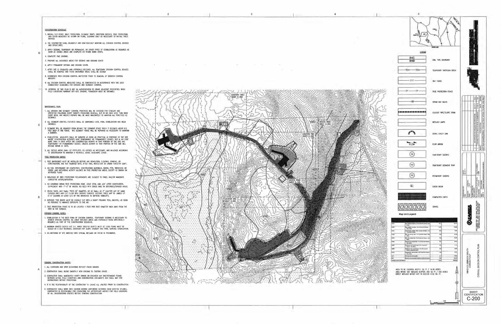
Appendix A – Maps and Drawings
• Site Maps
• Site Plans
Appendix B – Inspection and Maintenance Records
• Inspection & Maintenance Log
• Inspection Report
• Maintenance Report
Appendix C – Calculations and Supporting Documentation

Erosion and Sediment Control Plan
Wind Colebrook South
Colebrook, Connecticut
Zapata Incorporated Project No.: 1355
November 2010
APPENDIX A
MAPS AND DRAWINGS

Erosion and Sediment Control Plan
Wind Colebrook South
Colebrook, Connecticut
Zapata Incorporated Project No.: 1355
November 2010 page A-1

Erosion and Sediment Control Plan
Wind Colebrook South
Colebrook, Connecticut
Zapata Incorporated Project No.: 1355
November 2010 Page A-2

Erosion and Sediment Control Plan
Wind Colebrook South
Colebrook, Connecticut
Zapata Incorporated Project No.: 1355
November 2010 Page A-3

Erosion and Sediment Control Plan
Wind Colebrook South
Colebrook, Connecticut
Zapata Incorporated Project No.: 1355
November 2010 Page A-4

Erosion and Sediment Control Plan
Wind Colebrook South
Colebrook, Connecticut
Zapata Incorporated Project No.: 1355
November 2010 Page A-5


Erosion and Sediment Control Plan
Wind Colebrook South
Colebrook, Connecticut
Zapata Incorporated Project No.: 1355
November 2010
APPENDIX B
INSPECTION AND MAINTENANCE RECORDS

Erosion and Sediment Control Plan
Wind Colebrook South
Colebrook, Connecticut
Zapata Incorporated Project No.: 1355
November 2010 Page B-1
INSPECTOR CERTIFICATION
Project: Wind Colebrook South
Project Location: 29 Flagg Hill Road
Colebrook, Connecticut
Contractor:
Address:
Phone:
Fax:
CONSTRUCTION INSPECTION & MAINTENANCE LOG
Date Activity Description (1) Report No.
� Inspection
�
Maintenance
By: ___________________________________
� Inspection
�
Maintenance
By: ___________________________________
� Inspection
�
Maintenance
By: ___________________________________
� Inspection
�
Maintenance
By: ___________________________________
� Inspection
�
Maintenance
By: ___________________________________
� Inspection
�
Maintenance
By: ___________________________________
� Inspection
�
Maintenance
By: ___________________________________
� Inspection
�
Maintenance
By: ___________________________________
� Inspection
�
Maintenance
By: ___________________________________
� Inspection
�
Maintenance
By: ___________________________________

Erosion and Sediment Control Plan
Wind Colebrook South
Colebrook, Connecticut
Zapata Incorporated Project No.: 1355
November 2010 Page B-2
CONSTRUCTION SITE INSPECTION REPORT
General Information
Project Name: Wind Colebrook South
Location: 29 Flagg Hill Road
Colebrook, Connecticut
CT DEP Tracking No. (1) Report No.
Date of Inspection: Start / End
Time:
Inspector’s Name(s):
Inspector’s Title(s):
Inspector’s Contact
Information:
Describe present phase
of construction:
Type of Inspection:
� Regular � Pre-storm event � During storm event � Post-storm event
Weather Information
Has it rained since the last inspection?
�Yes �No
If yes, provide:
Storm Start Date & Time: Storm Duration (hrs): Approximate Rainfall
(in):
Weather at time of this inspection?
Discharge Information (A)
Do you suspect that discharges may have occurred since the last inspection?
�Yes �No
Are there any discharges at the time of inspection?
�Yes �No
Describe location of any discharges from the site:

Erosion and Sediment Control Plan
Wind Colebrook South
Colebrook, Connecticut
Zapata Incorporated Project No.: 1355
November 2010 Page B-3
SITE-SPECIFIC BMPs
(B) BMP Description
BMP Installed
and Operating
Properly?
Corrective Action Needed
Date for corrective
action / responsible
party
1
�Yes �No
2
�Yes �No
3
�Yes �No
4
�Yes �No
5
�Yes �No
6
�Yes �No
7
�Yes �No
8
�Yes �No
9
�Yes �No
10
�Yes �No
11
�Yes �No
12
�Yes �No
13
�Yes �No
14
�Yes �No
15
�Yes �No
16
�Yes �No
17
�Yes �No
18
�Yes �No
19
�Yes �No

Erosion and Sediment Control Plan
Wind Colebrook South
Colebrook, Connecticut
Zapata Incorporated Project No.: 1355
November 2010 Page B-4
OVERALL SITE ISSUES
(C) BMP/activity Implemented? Maintained? Corrective
Action
Date for corrective
action/responsible
person
1 Are all slopes and
disturbed areas
not actively being
worked properly
stabilized?
�Yes �No �Yes �No
2 Are natural
resource areas
(e.g., streams,
wetlands, mature
trees, etc.)
protected with
barriers or similar
BMPs?
�Yes �No �Yes �No
3 Are perimeter
controls and
sediment barriers
adequately
installed (keyed
into substrate) and
maintained?
�Yes �No �Yes �No
4 Are discharge
points and
receiving waters
free of sediment
deposits?
�Yes �No �Yes �No
5 Are storm drain
inlets properly
protected?
�Yes �No �Yes �No
6 Is there evidence
of sediment being
tracked into the
street?
�Yes �No �Yes �No
7 Is trash/litter from
work areas
collected and
placed in covered
�Yes �No �Yes �No

Erosion and Sediment Control Plan
Wind Colebrook South
Colebrook, Connecticut
Zapata Incorporated Project No.: 1355
November 2010 Page B-5
(C) BMP/activity Implemented? Maintained? Corrective
Action
Date for corrective
action/responsible
person
dumpsters?
8 Are washout
facilities (e.g.,
paint, stucco,
concrete)
available, clearly
marked, and
maintained?
�Yes �No �Yes �No
9 Are vehicle and
equipment
fueling, cleaning,
and maintenance
areas free of
spills, leaks, or
any other
deleterious
material?
�Yes �No �Yes �No
10 Are materials that
are potential
stormwater
contaminants
stored inside or
under cover?
�Yes �No �Yes �No
11 Are non-
stormwater
discharges (e.g.,
wash water,
dewatering)
properly
controlled?
�Yes �No �Yes �No
12 (Other)
�Yes �No �Yes �No
13 (Other) �Yes �No �Yes �No

Erosion and Sediment Control Plan
Wind Colebrook South
Colebrook, Connecticut
Zapata Incorporated Project No.: 1355
November 2010 Page B-6
(C) BMP/activity Implemented? Maintained? Corrective
Action
Date for corrective
action/responsible
person
GENERAL INSPECTION COMMENTS AND EXPLANATION
General Inspection Comments (D)
Is other descriptive information attached to this inspection report?
�Yes �No
Plan Information (E)
Were all current plan BMP’s in place at the time of inspection?
�Yes �No
Are additional BMP’s required?
�Yes �No
Does the plan need to be updated?
�Yes �No
Explanation of additional BMP and Plan update requirements:

Erosion and Sediment Control Plan
Wind Colebrook South
Colebrook, Connecticut
Zapata Incorporated Project No.: 1355
November 2010 Page B-7
Certification statement:
I certify that I have thoroughly and completely reviewed the Stormwater Pollution Control Plan
for the site. I further certify, based on such review and in my professional judgment, that the
Stormwater Pollution Control Plan has been prepared in accordance with the Connecticut
Guidelines for Soil Erosion and Sediment Control, as amended, and the conditions for the
General Permit for the Discharge of Stormwater and Dewatering Wastewaters from Construction
Activities issued on October 1, 2002 (or as reissued or modified), and the controls required for
such Plan are appropriate for the site. I am aware that there are significant penalties for false
statements in this certification, including the possibility of fine and imprisonment for knowingly
making false statements.
Name: ____________________________________________________________
(Please print)
Signature: ____________________________________________________________
Title: ___________________________ Date: ______________________
.

Erosion and Sediment Control Plan
Wind Colebrook South
Colebrook, Connecticut
Zapata Incorporated Project No.: 1355
November 2010 Page B-8
CONSTRUCTION SITE MAINTENANCE REPORT
General Information
Project Name: Wind Colebrook South
Location: 29 Flagg Hill Road
Colebrook, Connecticut
CT DEP Tracking No.: (1) Report No.
Date of Maintenance: Start / End
Time:
Describe present phase
of construction:
Type of Maintenance:
� Regular � Pre-storm event � Post-storm event � Plan Update
Maintenance Information
Inspection Report
Reference (No., Item)
Maintenance performed:
Performed by:
Inspection Report
Reference (No., Item)
Maintenance performed:
Performed by:
Inspection Report
Reference (No., Item)
Maintenance performed:
Performed by:
Inspection Report
Reference (No., Item)
Maintenance performed:
Performed by:
Inspection Report
Reference (No., Item)
Maintenance performed:
Performed by:

Erosion and Sediment Control Plan
Wind Colebrook South
Colebrook, Connecticut
Zapata Incorporated Project No.: 1355
November 2010 Page B-9
Inspection Report
Reference (No., Item)
Maintenance performed:
Performed by:
Inspection Report
Reference (No., Item)
Maintenance performed:
Performed by:
Inspection Report
Reference (No., Item)
Maintenance performed:
Performed by:
Inspection Report
Reference (No., Item)
Maintenance performed:
Performed by:
Inspection Report
Reference (No., Item)
Maintenance performed:
Performed by:
Inspection Report
Reference (No., Item)
Maintenance performed:
Performed by:
Inspection Report
Reference (No., Item)
Maintenance performed:
Performed by:
Inspection Report
Reference (No., Item)
Maintenance performed:
Performed by:

Erosion and Sediment Control Plan
Wind Colebrook South
Colebrook, Connecticut
Zapata Incorporated Project No.: 1355
November 2010 Page B-10
Certification statement:
I certify that I have thoroughly and completely reviewed the Stormwater Pollution Control Plan
for the site. I further certify, based on such review and in my professional judgment, that the
Stormwater Pollution Control Plan has been prepared in accordance with the Connecticut
Guidelines for Soil Erosion and Sediment Control, as amended, and the conditions for the
General Permit for the Discharge of Stormwater and Dewatering Wastewaters from Construction
Activities issued on October 1, 2002 (or as reissued or modified), and the controls required for
such Plan are appropriate for the site. I am aware that there are significant penalties for false
statements in this certification, including the possibility of fine and imprisonment for knowingly
making false statements.
Name: ____________________________________________________________
Signature: ____________________________________________________________
Title: ___________________________ Date: ______________________

Erosion and Sediment Control Plan
Wind Colebrook South
Colebrook, Connecticut
Zapata Incorporated Project No.: 1355
November 2010
APPENDIX C
CALCULATIONS AND SUPPORTING DOCUMENTATION

Permanent Diversion (PD) - Basin 1A
County: Litchfield, CT
10-yr, 24-hr Rainfall Amount (in): 4.7 in
Basin Area (AC): 1.7 AC
10-yr, 24-hr Pipe Runoff Rate (cfs): 7.46 cfs
Lining Type (Riprap, Concrete, or Flagstone): Riprap
Riprap Type (Standard, Intermediate, or Modified) Standard
Maximum Permissible Velocity for Material (fps): 14 fps
Channel Shape: Trapezoidal
Channel Slope (ft/ft): 0.05
Channel Side Slope: 2.0 :1
Channel Base Width (ft): 2.0 ft 2' minimum
Channel Depth (ft): 0.75 ft
Channel Area: 2.625 sf
Channel Perimeter (ft): 5.35 ft
Channel Top Width (ft): 5.0 ft 4' minimum
Mannings Roughness Coefficient, "n": 0.041
Assumed depth flow depth (ft): 0.75 ft
Assumed Flow Area (sf): 2.625 sf
Assumed Wetted Perimeter (ft): 5.4 ft
Assumed Hydraulic Radius (ft): 0.49 ft
Assumed Velocity (fps): 5.05 fps
Assumed Flow Rate (cfs): 13.26 cfs
Minimum Ridge Width (ft): 4 ft 4' minimum
Minimum Freeboard (ft): 0.3 ft
Assumed Freeboard (ft): 1.0 ft
Assumed Ridge Width (ft): 4.0 ft
Permanent Diversion (PD) Design
Per 2002 Connecticut Guidelines for Soil Erosion and Sediment Control, Chapter 5, Section 7

Permanent Diversion (PD) - Basin 1B
County: Litchfield, CT
10-yr, 24-hr Rainfall Amount (in): 4.7 in
Basin Area (AC): 1.9 AC
10-yr, 24-hr Pipe Runoff Rate (cfs): 8.66 cfs
Lining Type (Riprap, Concrete, or Flagstone): Riprap
Riprap Type (Standard, Intermediate, or Modified) Standard
Maximum Permissible Velocity for Material (fps): 14 fps
Channel Shape: Trapezoidal
Channel Slope (ft/ft): 0.20
Channel Side Slope: 2.0 :1
Channel Base Width (ft): 2.0 ft 2' minimum
Channel Depth (ft): 0.50 ft
Channel Area: 1.5 sf
Channel Perimeter (ft): 4.24 ft
Channel Top Width (ft): 4.0 ft 4' minimum
Mannings Roughness Coefficient, "n": 0.041
Assumed depth flow depth (ft): 0.5 ft
Assumed Flow Area (sf): 1.5 sf
Assumed Wetted Perimeter (ft): 4.2 ft
Assumed Hydraulic Radius (ft): 0.35 ft
Assumed Velocity (fps): 8.13 fps
Assumed Flow Rate (cfs): 12.20 cfs
Minimum Ridge Width (ft): 4 ft 4' minimum
Minimum Freeboard (ft): 0.3 ft
Assumed Freeboard (ft): 1.0 ft
Assumed Ridge Width (ft): 4.0 ft
Permanent Diversion (PD) Design
Per 2002 Connecticut Guidelines for Soil Erosion and Sediment Control, Chapter 5, Section 7

Permanent Diversion (PD) - Basin 2A
County: Litchfield, CT
10-yr, 24-hr Rainfall Amount (in): 4.7 in
Basin Area (AC): 0.2 AC
10-yr, 24-hr Pipe Runoff Rate (cfs): 0.98 cfs
Lining Type (Riprap, Concrete, or Flagstone): Riprap
Riprap Type (Standard, Intermediate, or Modified) Standard
Maximum Permissible Velocity for Material (fps): 14 fps
Channel Shape: Trapezoidal
Channel Slope (ft/ft): 0.20
Channel Side Slope: 2.0 :1
Channel Base Width (ft): 2.0 ft 2' minimum
Channel Depth (ft): 0.20 ft
Channel Area: 0.48 sf
Channel Perimeter (ft): 2.89 ft
Channel Top Width (ft): 4.0 ft 4' minimum
Mannings Roughness Coefficient, "n": 0.041
Assumed depth flow depth (ft): 0.2 ft
Assumed Flow Area (sf): 0.48 sf
Assumed Wetted Perimeter (ft): 2.9 ft
Assumed Hydraulic Radius (ft): 0.17 ft
Assumed Velocity (fps): 4.91 fps
Assumed Flow Rate (cfs): 2.35 cfs
Minimum Ridge Width (ft): 4 ft 4' minimum
Minimum Freeboard (ft): 0.3 ft
Assumed Freeboard (ft): 1.0 ft
Assumed Ridge Width (ft): 4.0 ft
Permanent Diversion (PD) Design
Per 2002 Connecticut Guidelines for Soil Erosion and Sediment Control, Chapter 5, Section 7

Permanent Diversion (PD) - Basin 3A
County: Litchfield, CT
10-yr, 24-hr Rainfall Amount (in): 4.7 in
Basin Area (AC): 1.5 AC
10-yr, 24-hr Pipe Runoff Rate (cfs): 6.56 cfs
Lining Type (Riprap, Concrete, or Flagstone): Riprap
Riprap Type (Standard, Intermediate, or Modified) Standard
Maximum Permissible Velocity for Material (fps): 14 fps
Channel Shape: Trapezoidal
Channel Slope (ft/ft): 0.10
Channel Side Slope: 2.0 :1
Channel Base Width (ft): 2.0 ft 2' minimum
Channel Depth (ft): 0.50 ft
Channel Area: 1.5 sf
Channel Perimeter (ft): 4.24 ft
Channel Top Width (ft): 4.0 ft 4' minimum
Mannings Roughness Coefficient, "n": 0.041
Assumed depth flow depth (ft): 0.5 ft
Assumed Flow Area (sf): 1.5 sf
Assumed Wetted Perimeter (ft): 4.2 ft
Assumed Hydraulic Radius (ft): 0.35 ft
Assumed Velocity (fps): 5.75 fps
Assumed Flow Rate (cfs): 8.63 cfs
Minimum Ridge Width (ft): 4 ft 4' minimum
Minimum Freeboard (ft): 0.3 ft
Assumed Freeboard (ft): 1.0 ft
Assumed Ridge Width (ft): 4.0 ft
Permanent Diversion (PD) Design
Per 2002 Connecticut Guidelines for Soil Erosion and Sediment Control, Chapter 5, Section 7

Permanent Diversion (PD) - Basin 3B
County: Litchfield, CT
10-yr, 24-hr Rainfall Amount (in): 4.7 in
Basin Area (AC): 3.0 AC
10-yr, 24-hr Pipe Runoff Rate (cfs): 13.40 cfs
Lining Type (Riprap, Concrete, or Flagstone): Riprap
Riprap Type (Standard, Intermediate, or Modified) Standard
Maximum Permissible Velocity for Material (fps): 14 fps
Channel Shape: Trapezoidal
Channel Slope (ft/ft): 0.05
Channel Side Slope: 2.0 :1
Channel Base Width (ft): 2.0 ft 2' minimum
Channel Depth (ft): 1.00 ft
Channel Area: 4 sf
Channel Perimeter (ft): 6.47 ft
Channel Top Width (ft): 6.0 ft 4' minimum
Mannings Roughness Coefficient, "n": 0.041
Assumed depth flow depth (ft): 1 ft
Assumed Flow Area (sf): 4 sf
Assumed Wetted Perimeter (ft): 6.5 ft
Assumed Hydraulic Radius (ft): 0.62 ft
Assumed Velocity (fps): 5.90 fps
Assumed Flow Rate (cfs): 23.58 cfs
Minimum Ridge Width (ft): 4 ft 4' minimum
Minimum Freeboard (ft): 0.3 ft
Assumed Freeboard (ft): 1.0 ft
Assumed Ridge Width (ft): 4.0 ft
Permanent Diversion (PD) Design
Per 2002 Connecticut Guidelines for Soil Erosion and Sediment Control, Chapter 5, Section 7

Permanent Diversion (PD) - Basin 5A
County: Litchfield, CT
10-yr, 24-hr Rainfall Amount (in): 4.7 in
Basin Area (AC): 1.3 AC
10-yr, 24-hr Pipe Runoff Rate (cfs): 5.94 cfs
Lining Type (Riprap, Concrete, or Flagstone): Riprap
Riprap Type (Standard, Intermediate, or Modified) Standard
Maximum Permissible Velocity for Material (fps): 14 fps
Channel Shape: Trapezoidal
Channel Slope (ft/ft): 0.06
Channel Side Slope: 2.0 :1
Channel Base Width (ft): 2.0 ft 2' minimum
Channel Depth (ft): 0.75 ft
Channel Area: 2.625 sf
Channel Perimeter (ft): 5.35 ft
Channel Top Width (ft): 5.0 ft 4' minimum
Mannings Roughness Coefficient, "n": 0.041
Assumed depth flow depth (ft): 0.75 ft
Assumed Flow Area (sf): 2.625 sf
Assumed Wetted Perimeter (ft): 5.4 ft
Assumed Hydraulic Radius (ft): 0.49 ft
Assumed Velocity (fps): 5.53 fps
Assumed Flow Rate (cfs): 14.53 cfs
Minimum Ridge Width (ft): 4 ft 4' minimum
Minimum Freeboard (ft): 0.3 ft
Assumed Freeboard (ft): 1.0 ft
Assumed Ridge Width (ft): 4.0 ft
Permanent Diversion (PD) Design
Per 2002 Connecticut Guidelines for Soil Erosion and Sediment Control, Chapter 5, Section 7
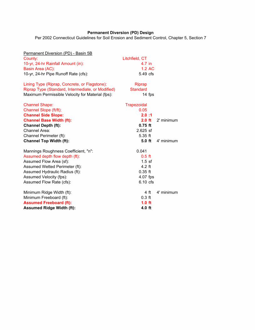
Permanent Diversion (PD) - Basin 5B
County: Litchfield, CT
10-yr, 24-hr Rainfall Amount (in): 4.7 in
Basin Area (AC): 1.2 AC
10-yr, 24-hr Pipe Runoff Rate (cfs): 5.49 cfs
Lining Type (Riprap, Concrete, or Flagstone): Riprap
Riprap Type (Standard, Intermediate, or Modified) Standard
Maximum Permissible Velocity for Material (fps): 14 fps
Channel Shape: Trapezoidal
Channel Slope (ft/ft): 0.05
Channel Side Slope: 2.0 :1
Channel Base Width (ft): 2.0 ft 2' minimum
Channel Depth (ft): 0.75 ft
Channel Area: 2.625 sf
Channel Perimeter (ft): 5.35 ft
Channel Top Width (ft): 5.0 ft 4' minimum
Mannings Roughness Coefficient, "n": 0.041
Assumed depth flow depth (ft): 0.5 ft
Assumed Flow Area (sf): 1.5 sf
Assumed Wetted Perimeter (ft): 4.2 ft
Assumed Hydraulic Radius (ft): 0.35 ft
Assumed Velocity (fps): 4.07 fps
Assumed Flow Rate (cfs): 6.10 cfs
Minimum Ridge Width (ft): 4 ft 4' minimum
Minimum Freeboard (ft): 0.3 ft
Assumed Freeboard (ft): 1.0 ft
Assumed Ridge Width (ft): 4.0 ft
Permanent Diversion (PD) Design
Per 2002 Connecticut Guidelines for Soil Erosion and Sediment Control, Chapter 5, Section 7

Permanent Diversion (PD) - Basin 6B
County: Litchfield, CT
10-yr, 24-hr Rainfall Amount (in): 4.7 in
Basin Area (AC): 1.2 AC
10-yr, 24-hr Pipe Runoff Rate (cfs): 5.49 cfs
Lining Type (Riprap, Concrete, or Flagstone): Riprap
Riprap Type (Standard, Intermediate, or Modified) Standard
Maximum Permissible Velocity for Material (fps): 14 fps
Channel Shape: Trapezoidal
Channel Slope (ft/ft): 0.05
Channel Side Slope: 2.0 :1
Channel Base Width (ft): 2.0 ft 2' minimum
Channel Depth (ft): 0.50 ft
Channel Area: 1.5 sf
Channel Perimeter (ft): 4.24 ft
Channel Top Width (ft): 4.0 ft 4' minimum
Mannings Roughness Coefficient, "n": 0.041
Assumed depth flow depth (ft): 0.5 ft
Assumed Flow Area (sf): 1.5 sf
Assumed Wetted Perimeter (ft): 4.2 ft
Assumed Hydraulic Radius (ft): 0.35 ft
Assumed Velocity (fps): 4.07 fps
Assumed Flow Rate (cfs): 6.10 cfs
Minimum Ridge Width (ft): 4 ft 4' minimum
Minimum Freeboard (ft): 0.3 ft
Assumed Freeboard (ft): 1.0 ft
Assumed Ridge Width (ft): 4.0 ft
Permanent Diversion (PD) Design
Per 2002 Connecticut Guidelines for Soil Erosion and Sediment Control, Chapter 5, Section 7

Permanent Diversion (PD) - Basin 6C
County: Litchfield, CT
10-yr, 24-hr Rainfall Amount (in): 4.7 in
Basin Area (AC): 1.2 AC
10-yr, 24-hr Pipe Runoff Rate (cfs): 5.31 cfs
Lining Type (Riprap, Concrete, or Flagstone): Riprap
Riprap Type (Standard, Intermediate, or Modified) Standard
Maximum Permissible Velocity for Material (fps): 14 fps
Channel Shape: Trapezoidal
Channel Slope (ft/ft): 0.05
Channel Side Slope: 2.0 :1
Channel Base Width (ft): 2.0 ft 2' minimum
Channel Depth (ft): 0.75 ft
Channel Area: 2.625 sf
Channel Perimeter (ft): 5.35 ft
Channel Top Width (ft): 5.0 ft 4' minimum
Mannings Roughness Coefficient, "n": 0.041
Assumed depth flow depth (ft): 0.75 ft
Assumed Flow Area (sf): 2.625 sf
Assumed Wetted Perimeter (ft): 5.4 ft
Assumed Hydraulic Radius (ft): 0.49 ft
Assumed Velocity (fps): 5.05 fps
Assumed Flow Rate (cfs): 13.26 cfs
Minimum Ridge Width (ft): 4 ft 4' minimum
Minimum Freeboard (ft): 0.3 ft
Assumed Freeboard (ft): 1.0 ft
Assumed Ridge Width (ft): 4.0 ft
Permanent Diversion (PD) Design
Per 2002 Connecticut Guidelines for Soil Erosion and Sediment Control, Chapter 5, Section 7

Figure OP-1 Allowable Velocities for Various Soils
Pipe Discharge Rate Soil Texture Allowable Velocities (fps)
County: Litchfield, CT Sandy & sandy loam 2.5
10-yr, 24-hr Rainfall Amount (in): 4.7 in See Table 7-2, Chapter 7 Silt Loam 3
25-yr, 24-hr Rainfall Amount (in): 5.5 in See Table 7-2, Chapter 7 Sandy clay loam 3.5
Outfall Soil Type: Clay, fine gravel, graded loam to gravel Clay loam 4
Allowable Velocity without Erosion (fps): 4.5 fps See Figure OP-1, Chapter 5, Section 10 Clay, fine gravel, graded loam to gravel 4.5
Basin Area (AC): 1.7 AC Cobbles 5
10-yr, 24-hr Pipe Discharge Rate (cfs): 7.46 cfs Rational Method Formula Shale 5.5
25-yr, 24-hr Pipe Discharge Rate (cfs): 8.7 cfs Rational Method Formula
Pipe Diameter (in): 18 in
Pipe Area (sf): 1.8 sf
Hydraulic Radius (ft): 0.4 ft
Pipe Slope (ft/ft): 0.01 ft/ft
Manning's Coefficient, n: 0.013
Maximum Pipe Discharge Rate (cfs): 10.53 cfs Mannings Equation
10-yr, 24-hr Pipe Velocity (fps): 4.22 fps
25-yr, 24-hr Pipe Velocity (fps): 4.94 fps
Outlet Protection Design Discharge Rate (cfs): 8.73 cfs
Can pipe handle 10-yr, 24-hr discharge rate? Yes.
Is outlet protection required per CT Guidelines? Yes.
Outlet Protection - Cross-Drain from PD (Basin 1A)
Outlet Protection Design Discharge Rate (cfs): 8.73 cfs
Maximum Inside Culvert Width in Feet, Do 1.5 ft
Length of Apron, La = (1.7Q/Do^3/2)+8Do 20 ft See Apron Dimensions Calc. 1, Chapter 5, Section 10
Is there a well-defined channel downstream of apron? No See Apron Dimensions Calc. 2, Chapter 5, Section 10
Is tailwater elevation less than the center of the pipe? Yes See Apron Dimensions Calc. 2, Chapter 5, Section 10
Apron Width, W: 24.6 ft See Apron Dimensions Calc. 2, Chapter 5, Section 10
Outlet Protection (OP) Design
Per 2002 Connecticut Guidelines for Soil Erosion and Sediment Control, Chapter 5, Section 10

Figure OP-1 Allowable Velocities for Various Soils
Pipe Discharge Rate Soil Texture Allowable Velocities (fps)
County: Litchfield, CT Sandy & sandy loam 2.5
10-yr, 24-hr Rainfall Amount (in): 4.7 in See Table 7-2, Chapter 7 Silt Loam 3
25-yr, 24-hr Rainfall Amount (in): 5.5 in See Table 7-2, Chapter 7 Sandy clay loam 3.5
Outfall Soil Type: Clay, fine gravel, graded loam to gravel Clay loam 4
Allowable Velocity without Erosion (fps): 4.5 fps See Figure OP-1, Chapter 5, Section 10 Clay, fine gravel, graded loam to gravel 4.5
Basin Area (AC): 0.3 AC Cobbles 5
10-yr, 24-hr Pipe Discharge Rate (cfs): 1.12 cfs Rational Method Formula Shale 5.5
25-yr, 24-hr Pipe Discharge Rate (cfs): 1.3 cfs Rational Method Formula
Pipe Diameter (in): 18 in
Pipe Area (sf): 1.8 sf
Hydraulic Radius (ft): 0.4 ft
Pipe Slope (ft/ft): 0.01 ft/ft
Manning's Coefficient, n: 0.013
Maximum Pipe Discharge Rate (cfs): 10.53 cfs Mannings Equation
10-yr, 24-hr Pipe Velocity (fps): 0.63 fps
25-yr, 24-hr Pipe Velocity (fps): 0.74 fps
Outlet Protection Design Discharge Rate (cfs): 1.31 cfs
Can pipe handle 10-yr, 24-hr discharge rate? Yes.
Is outlet protection required per CT Guidelines? No.
Outlet Protection - Cross-Drain from PD (Basin 2A) No outlet protection required
Outlet Protection Design Discharge Rate (cfs): 1.31 cfs
Maximum Inside Culvert Width in Feet, Do 1.5 ft
Length of Apron, La = (1.7Q/Do^3/2)+8Do 13 ft See Apron Dimensions Calc. 1, Chapter 5, Section 10
Is there a well-defined channel downstream of apron? No See Apron Dimensions Calc. 2, Chapter 5, Section 10
Is tailwater elevation less than the center of the pipe? Yes See Apron Dimensions Calc. 2, Chapter 5, Section 10
Apron Width, W: 17.7 ft See Apron Dimensions Calc. 2, Chapter 5, Section 10
Outlet Protection (OP) Design
Per 2002 Connecticut Guidelines for Soil Erosion and Sediment Control, Chapter 5, Section 10

Figure OP-1 Allowable Velocities for Various Soils
Pipe Discharge Rate Soil Texture Allowable Velocities (fps)
County: Litchfield, CT Sandy & sandy loam 2.5
10-yr, 24-hr Rainfall Amount (in): 4.7 in See Table 7-2, Chapter 7 Silt Loam 3
25-yr, 24-hr Rainfall Amount (in): 5.5 in See Table 7-2, Chapter 7 Sandy clay loam 3.5
Outfall Soil Type: Clay, fine gravel, graded loam to gravel Clay loam 4
Allowable Velocity without Erosion (fps): 4.5 fps See Figure OP-1, Chapter 5, Section 10 Clay, fine gravel, graded loam to gravel 4.5
Basin Area (AC): 0.8 AC Cobbles 5
10-yr, 24-hr Pipe Discharge Rate (cfs): 3.35 cfs Rational Method Formula Shale 5.5
25-yr, 24-hr Pipe Discharge Rate (cfs): 3.9 cfs Rational Method Formula
Pipe Diameter (in): 24 in
Pipe Area (sf): 3.1 sf
Hydraulic Radius (ft): 0.5 ft
Pipe Slope (ft/ft): 0.05 ft/ft
Manning's Coefficient, n: 0.013
Maximum Pipe Discharge Rate (cfs): 50.72 cfs Mannings Equation
10-yr, 24-hr Pipe Velocity (fps): 1.07 fps
25-yr, 24-hr Pipe Velocity (fps): 1.25 fps
Outlet Protection Design Discharge Rate (cfs): 3.92 cfs
Can pipe handle 10-yr, 24-hr discharge rate? Yes.
Is outlet protection required per CT Guidelines? No.
Outlet Protection - Temporary Diversion (Basin 9A) No outlet protection required
Outlet Protection Design Discharge Rate (cfs): 3.92 cfs
Maximum Inside Culvert Width in Feet, Do 2.0 ft
Length of Apron, La = (1.7Q/Do^3/2)+8Do 18 ft See Apron Dimensions Calc. 1, Chapter 5, Section 10
Is there a well-defined channel downstream of apron? No See Apron Dimensions Calc. 2, Chapter 5, Section 10
Is tailwater elevation less than the center of the pipe? Yes See Apron Dimensions Calc. 2, Chapter 5, Section 10
Apron Width, W: 24.4 ft See Apron Dimensions Calc. 2, Chapter 5, Section 10
Outlet Protection (OP) Design
Per 2002 Connecticut Guidelines for Soil Erosion and Sediment Control, Chapter 5, Section 10

Figure OP-1 Allowable Velocities for Various Soils
Pipe Discharge Rate Soil Texture Allowable Velocities (fps)
County: Litchfield, CT Sandy & sandy loam 2.5
10-yr, 24-hr Rainfall Amount (in): 4.7 in See Table 7-2, Chapter 7 Silt Loam 3
25-yr, 24-hr Rainfall Amount (in): 5.5 in See Table 7-2, Chapter 7 Sandy clay loam 3.5
Outfall Soil Type: Sandy clay loam Clay loam 4
Allowable Velocity without Erosion (fps): 5.0 fps See Figure OP-1, Chapter 5, Section 10 Clay, fine gravel, graded loam to gravel 4.5
Basin Area (AC): 0.6 AC Cobbles 5
10-yr, 24-hr Pipe Discharge Rate (cfs): 2.55 cfs Rational Method Formula Shale 5.5
25-yr, 24-hr Pipe Discharge Rate (cfs): 3.0 cfs Rational Method Formula
Pipe Diameter (in): 24 in
Pipe Area (sf): 3.1 sf
Hydraulic Radius (ft): 0.5 ft
Pipe Slope (ft/ft): 0.20 ft/ft
Manning's Coefficient, n: 0.013
Maximum Pipe Discharge Rate (cfs): 101.44 cfs Mannings Equation
10-yr, 24-hr Pipe Velocity (fps): 0.81 fps
25-yr, 24-hr Pipe Velocity (fps): 0.95 fps
Outlet Protection Design Discharge Rate (cfs): 2.98 cfs
Can pipe handle 10-yr, 24-hr discharge rate? Yes.
Is outlet protection required per CT Guidelines? No.
Outlet Protection - Temporary Diversion (Basin 9B) No outlet protection required
Outlet Protection Design Discharge Rate (cfs): 2.98 cfs
Maximum Inside Culvert Width in Feet, Do 2.0 ft
Length of Apron, La = (1.7Q/Do^3/2)+8Do 18 ft See Apron Dimensions Calc. 1, Chapter 5, Section 10
Is there a well-defined channel downstream of apron? Yes See Apron Dimensions Calc. 2, Chapter 5, Section 10
Is tailwater elevation less than the center of the pipe? No See Apron Dimensions Calc. 2, Chapter 5, Section 10
Apron Width, W: Width of channel. ft See Apron Dimensions Calc. 2, Chapter 5, Section 10
Outlet Protection (OP) Design
Per 2002 Connecticut Guidelines for Soil Erosion and Sediment Control, Chapter 5, Section 10

Figure OP-1 Allowable Velocities for Various Soils
Pipe Discharge Rate Soil Texture Allowable Velocities (fps)
County: Litchfield, CT Sandy & sandy loam 2.5
10-yr, 24-hr Rainfall Amount (in): 4.7 in See Table 7-2, Chapter 7 Silt Loam 3
25-yr, 24-hr Rainfall Amount (in): 5.5 in See Table 7-2, Chapter 7 Sandy clay loam 3.5
Outfall Soil Type: Clay, fine gravel, graded loam to gravel Clay loam 4
Allowable Velocity without Erosion (fps): 4.5 fps See Figure OP-1, Chapter 5, Section 10 Clay, fine gravel, graded loam to gravel 4.5
Basin Area (AC): 0.6 AC Cobbles 5
10-yr, 24-hr Pipe Discharge Rate (cfs): 2.55 cfs Rational Method Formula Shale 5.5
25-yr, 24-hr Pipe Discharge Rate (cfs): 3.0 cfs Rational Method Formula
Pipe Diameter (in): 18 in
Pipe Area (sf): 1.8 sf
Hydraulic Radius (ft): 0.4 ft
Pipe Slope (ft/ft): 0.01 ft/ft
Manning's Coefficient, n: 0.013
Maximum Pipe Discharge Rate (cfs): 10.53 cfs Mannings Equation
10-yr, 24-hr Pipe Velocity (fps): 1.44 fps
25-yr, 24-hr Pipe Velocity (fps): 1.69 fps
Outlet Protection Design Discharge Rate (cfs): 2.98 cfs
Can pipe handle 10-yr, 24-hr discharge rate? Yes.
Is outlet protection required per CT Guidelines? No.
Outlet Protection - Cross-drain from PD (Basin 3A) No outlet protection required
Outlet Protection Design Discharge Rate (cfs): 2.98 cfs
Maximum Inside Culvert Width in Feet, Do 1.5 ft
Length of Apron, La = (1.7Q/Do^3/2)+8Do 15 ft See Apron Dimensions Calc. 1, Chapter 5, Section 10
Is there a well-defined channel downstream of apron? No See Apron Dimensions Calc. 2, Chapter 5, Section 10
Is tailwater elevation less than the center of the pipe? Yes See Apron Dimensions Calc. 2, Chapter 5, Section 10
Apron Width, W: 19.3 ft See Apron Dimensions Calc. 2, Chapter 5, Section 10
Outlet Protection (OP) Design
Per 2002 Connecticut Guidelines for Soil Erosion and Sediment Control, Chapter 5, Section 10

Figure OP-1 Allowable Velocities for Various Soils
Pipe Discharge Rate Soil Texture Allowable Velocities (fps)
County: Litchfield, CT Sandy & sandy loam 2.5
10-yr, 24-hr Rainfall Amount (in): 4.7 in See Table 7-2, Chapter 7 Silt Loam 3
25-yr, 24-hr Rainfall Amount (in): 5.5 in See Table 7-2, Chapter 7 Sandy clay loam 3.5
Outfall Soil Type: Sandy clay loam Clay loam 4
Allowable Velocity without Erosion (fps): 5.0 fps See Figure OP-1, Chapter 5, Section 10 Clay, fine gravel, graded loam to gravel 4.5
Basin Area (AC): 1.5 AC Cobbles 5
10-yr, 24-hr Pipe Discharge Rate (cfs): 6.70 cfs Rational Method Formula Shale 5.5
25-yr, 24-hr Pipe Discharge Rate (cfs): 7.8 cfs Rational Method Formula
Pipe Diameter (in): 24 in
Pipe Area (sf): 3.1 sf
Hydraulic Radius (ft): 0.5 ft
Pipe Slope (ft/ft): 0.10 ft/ft
Manning's Coefficient, n: 0.013
Maximum Pipe Discharge Rate (cfs): 71.73 cfs Mannings Equation
10-yr, 24-hr Pipe Velocity (fps): 2.13 fps
25-yr, 24-hr Pipe Velocity (fps): 2.49 fps
Outlet Protection Design Discharge Rate (cfs): 7.84 cfs
Can pipe handle 10-yr, 24-hr discharge rate? Yes.
Is outlet protection required per CT Guidelines? Yes.
Outlet Protection - Permanent Diversion (Basin 3B)
Outlet Protection Design Discharge Rate (cfs): 7.84 cfs
Maximum Inside Culvert Width in Feet, Do 2.0 ft
Length of Apron, La = (1.7Q/Do^3/2)+8Do 21 ft See Apron Dimensions Calc. 1, Chapter 5, Section 10
Is there a well-defined channel downstream of apron? Yes See Apron Dimensions Calc. 2, Chapter 5, Section 10
Is tailwater elevation less than the center of the pipe? No See Apron Dimensions Calc. 2, Chapter 5, Section 10
Apron Width, W: Width of channel. ft See Apron Dimensions Calc. 2, Chapter 5, Section 10
Outlet Protection (OP) Design
Per 2002 Connecticut Guidelines for Soil Erosion and Sediment Control, Chapter 5, Section 10

Temporary Sediment Trap 1
Required Treatment Volume per Acre Disturbed Area: 134.0 CY/AC See Trap Capacity, 5-11-25
Disturbed Drainage Area: 2.5 AC
Treatment Volume Required: 335.0 CY
Maximum Disturbed Drainage Area per Sediment Trap: 5.0 AC See Applicability, 5-11-25
Number of Sediment Traps Required: 1.0
Treatment Volume Required per Trap: 335.0 CY
Wet Storage Required per Trap: 167.5 CY See Trap Capacity, 5-11-25
Assumed Wet Storage Depth, Dw: 2.50 FT See Figure TST-2, 5-11-27
Assumed Bottom Width, Wb: 20.0 FT
Assumed Bottom Length, Lb: 55.0 FT
Assumed Side Slope: 2.0 FT/FT See Slope Limitations, 5-11-26
Assumed Upstream Slope: 2.0 FT/FT
Assumed Downstream Slope: 2.0 FT/FT See Slope Limitations, 5-11-26
Wet Storage Surface Width: 30.0 FT
Wet Storage Surface Length: 65.0 FT
Wet Storage Surface Area, Aw: 1,950.0 SF See Figure TST-1, 5-11-26
Wet Storage Volume, Vw: 4,875.0 CF See Figure TST-1, 5-11-26
Wet Storage Volume, Vw: 180.6 CY See Figure TST-1, 5-11-26
Is Vw greater than required? Yes
Dry Storage Volume Required per Trap: 154.4 CY
Assumed Dry Storage Depth, Dd: 2.00 FT See Figure TST-2, 5-11-27
Dry Storage Surface Width: 38.0 FT
Dry Storage Surface Length: 73.0 FT
Dry Storage Surface Area, Ad: 2,774.0 SF See Figure TST-1, 5-11-26
Dry Storage Volume, Vd: 4,724.0 CF See Figure TST-1, 5-11-26
Dry Storage Volume, Vd: 175.0 CY See Figure TST-1, 5-11-26
Dry Storage Percentage of Total: 49%
Total Provided Storage Volume, V: 355.5 CY
Is V greater than Required Treatment Volume? Yes
Freeboard: 1.0 FT See Figure TST-4, 5-11-29
Embankment Height, H: 3.00 FT See Figure TST-2, 5-11-27
Embankment Top Width, W: 2.5 FT See Figure TST-2, 5-11-27
Temporary Sediment Trap (TST) Design
Per 2002 Connecticut Guidelines for Soil Erosion and Sediment Control

Temporary Sediment Trap 2
Required Treatment Volume per Acre Disturbed Area: 134.0 CY/AC See Trap Capacity, 5-11-25
Disturbed Drainage Area: 1.1 AC
Treatment Volume Required: 147.4 CY
Maximum Disturbed Drainage Area per Sediment Trap: 5.0 AC See Applicability, 5-11-25
Number of Sediment Traps Required: 1.0
Treatment Volume Required per Trap: 147.4 CY
Wet Storage Required per Trap: 73.7 CY See Trap Capacity, 5-11-25
Assumed Wet Storage Depth, Dw: 2.00 FT See Figure TST-2, 5-11-27
Assumed Bottom Width, Wb: 15.0 FT
Assumed Bottom Length, Lb: 40.0 FT
Assumed Side Slope: 2.0 FT/FT See Slope Limitations, 5-11-26
Assumed Upstream Slope: 2.0 FT/FT
Assumed Downstream Slope: 2.0 FT/FT See Slope Limitations, 5-11-26
Wet Storage Surface Width: 23.0 FT
Wet Storage Surface Length: 48.0 FT
Wet Storage Surface Area, Aw: 1,104.0 SF See Figure TST-1, 5-11-26
Wet Storage Volume, Vw: 2,208.0 CF See Figure TST-1, 5-11-26
Wet Storage Volume, Vw: 81.8 CY See Figure TST-1, 5-11-26
Is Vw greater than required? Yes
Dry Storage Volume Required per Trap: 65.6 CY
Assumed Dry Storage Depth, Dd: 1.50 FT See Figure TST-2, 5-11-27
Dry Storage Surface Width: 29.0 FT
Dry Storage Surface Length: 54.0 FT
Dry Storage Surface Area, Ad: 1,566.0 SF See Figure TST-1, 5-11-26
Dry Storage Volume, Vd: 2,002.5 CF See Figure TST-1, 5-11-26
Dry Storage Volume, Vd: 74.2 CY See Figure TST-1, 5-11-26
Dry Storage Percentage of Total: 48%
Total Provided Storage Volume, V: 155.9 CY
Is V greater than Required Treatment Volume? Yes
Freeboard: 1.0 FT See Figure TST-4, 5-11-29
Embankment Height, H: 2.50 FT See Figure TST-2, 5-11-27
Embankment Top Width, W: 2.5 FT See Figure TST-2, 5-11-27
Temporary Sediment Trap (TST) Design
Per 2002 Connecticut Guidelines for Soil Erosion and Sediment Control

Temporary Sediment Trap 2A
Required Treatment Volume per Acre Disturbed Area: 134.0 CY/AC See Trap Capacity, 5-11-25
Disturbed Drainage Area: 3.2 AC
Treatment Volume Required: 424.8 CY
Maximum Disturbed Drainage Area per Sediment Trap: 5.0 AC See Applicability, 5-11-25
Number of Sediment Traps Required: 1.0
Treatment Volume Required per Trap: 424.8 CY
Wet Storage Required per Trap: 212.4 CY See Trap Capacity, 5-11-25
Assumed Wet Storage Depth, Dw: 3.00 FT See Figure TST-2, 5-11-27
Assumed Bottom Width, Wb: 20.0 FT
Assumed Bottom Length, Lb: 55.0 FT
Assumed Side Slope: 2.0 FT/FT See Slope Limitations, 5-11-26
Assumed Upstream Slope: 2.0 FT/FT
Assumed Downstream Slope: 2.0 FT/FT See Slope Limitations, 5-11-26
Wet Storage Surface Width: 32.0 FT
Wet Storage Surface Length: 67.0 FT
Wet Storage Surface Area, Aw: 2,144.0 SF See Figure TST-1, 5-11-26
Wet Storage Volume, Vw: 6,432.0 CF See Figure TST-1, 5-11-26
Wet Storage Volume, Vw: 238.2 CY See Figure TST-1, 5-11-26
Is Vw greater than required? Yes
Dry Storage Volume Required per Trap: 186.6 CY
Assumed Dry Storage Depth, Dd: 2.00 FT See Figure TST-2, 5-11-27
Dry Storage Surface Width: 40.0 FT
Dry Storage Surface Length: 75.0 FT
Dry Storage Surface Area, Ad: 3,000.0 SF See Figure TST-1, 5-11-26
Dry Storage Volume, Vd: 5,144.0 CF See Figure TST-1, 5-11-26
Dry Storage Volume, Vd: 190.5 CY See Figure TST-1, 5-11-26
Dry Storage Percentage of Total: 44%
Total Provided Storage Volume, V: 428.7 CY
Is V greater than Required Treatment Volume? Yes
Freeboard: 1.0 FT See Figure TST-4, 5-11-29
Embankment Height, H: 3.00 FT See Figure TST-2, 5-11-27
Embankment Top Width, W: 2.5 FT See Figure TST-2, 5-11-27
Temporary Sediment Trap (TST) Design
Per 2002 Connecticut Guidelines for Soil Erosion and Sediment Control

Temporary Sediment Trap 3
Required Treatment Volume per Acre Disturbed Area: 134.0 CY/AC See Trap Capacity, 5-11-25
Disturbed Drainage Area: 0.6 AC
Treatment Volume Required: 81.7 CY
Maximum Disturbed Drainage Area per Sediment Trap: 5.0 AC See Applicability, 5-11-25
Number of Sediment Traps Required: 1.0
Treatment Volume Required per Trap: 81.7 CY
Wet Storage Required per Trap: 40.9 CY See Trap Capacity, 5-11-25
Assumed Wet Storage Depth, Dw: 2.00 FT See Figure TST-2, 5-11-27
Assumed Bottom Width, Wb: 10.0 FT
Assumed Bottom Length, Lb: 30.0 FT
Assumed Side Slope: 2.0 FT/FT See Slope Limitations, 5-11-26
Assumed Upstream Slope: 2.0 FT/FT
Assumed Downstream Slope: 2.0 FT/FT See Slope Limitations, 5-11-26
Wet Storage Surface Width: 18.0 FT
Wet Storage Surface Length: 38.0 FT
Wet Storage Surface Area, Aw: 684.0 SF See Figure TST-1, 5-11-26
Wet Storage Volume, Vw: 1,368.0 CF See Figure TST-1, 5-11-26
Wet Storage Volume, Vw: 50.7 CY See Figure TST-1, 5-11-26
Is Vw greater than required? Yes
Dry Storage Volume Required per Trap: 31.1 CY
Assumed Dry Storage Depth, Dd: 1.50 FT See Figure TST-2, 5-11-27
Dry Storage Surface Width: 24.0 FT
Dry Storage Surface Length: 44.0 FT
Dry Storage Surface Area, Ad: 1,056.0 SF See Figure TST-1, 5-11-26
Dry Storage Volume, Vd: 1,305.0 CF See Figure TST-1, 5-11-26
Dry Storage Volume, Vd: 48.3 CY See Figure TST-1, 5-11-26
Dry Storage Percentage of Total: 49%
Total Provided Storage Volume, V: 99.0 CY
Is V greater than Required Treatment Volume? Yes
Freeboard: 1.0 FT See Figure TST-4, 5-11-29
Embankment Height, H: 2.50 FT See Figure TST-2, 5-11-27
Embankment Top Width, W: 2.5 FT See Figure TST-2, 5-11-27
Temporary Sediment Trap (TST) Design
Per 2002 Connecticut Guidelines for Soil Erosion and Sediment Control

Temporary Sediment Trap 4A
Required Treatment Volume per Acre Disturbed Area: 134.0 CY/AC See Trap Capacity, 5-11-25
Drainage Area: 2.0 AC
Treatment Volume Required: 263.3 CY
Maximum Disturbed Drainage Area per Sediment Trap: 5.0 AC See Applicability, 5-11-25
Number of Sediment Traps Required: 1.0
Treatment Volume Required per Trap: 263.3 CY
Wet Storage Required per Trap: 131.7 CY See Trap Capacity, 5-11-25
Assumed Wet Storage Depth, Dw: 2.00 FT See Figure TST-2, 5-11-27
Assumed Bottom Width, Wb: 20.0 FT
Assumed Bottom Length, Lb: 60.0 FT
Assumed Side Slope: 2.0 FT/FT See Slope Limitations, 5-11-26
Assumed Upstream Slope: 2.0 FT/FT
Assumed Downstream Slope: 2.0 FT/FT See Slope Limitations, 5-11-26
Wet Storage Surface Width: 28.0 FT
Wet Storage Surface Length: 68.0 FT
Wet Storage Surface Area, Aw: 1,904.0 SF See Figure TST-1, 5-11-26
Wet Storage Volume, Vw: 3,808.0 CF See Figure TST-1, 5-11-26
Wet Storage Volume, Vw: 141.0 CY See Figure TST-1, 5-11-26
Is Vw greater than required? Yes
Dry Storage Volume Required per Trap: 122.3 CY
Assumed Dry Storage Depth, Dd: 2.00 FT See Figure TST-2, 5-11-27
Dry Storage Surface Width: 36.0 FT
Dry Storage Surface Length: 76.0 FT
Dry Storage Surface Area, Ad: 2,736.0 SF See Figure TST-1, 5-11-26
Dry Storage Volume, Vd: 4,640.0 CF See Figure TST-1, 5-11-26
Dry Storage Volume, Vd: 171.9 CY See Figure TST-1, 5-11-26
Dry Storage Percentage of Total: 55%
Total Provided Storage Volume, V: 312.9 CY
Is V greater than Required Treatment Volume? Yes
Freeboard: 1.0 FT See Figure TST-4, 5-11-29
Embankment Height, H: 3.00 FT See Figure TST-2, 5-11-27
Embankment Top Width, W: 2.0 FT See Figure TST-2, 5-11-27
Temporary Sediment Trap (TST) Design
Per 2002 Connecticut Guidelines for Soil Erosion and Sediment Control
W:\Projects\BNE Energy Inc\Data\Wind Colbrook South\Calculations\Temporary Sediment Trap Calculations 2011-03-09

Temporary Sediment Trap 4B
Required Treatment Volume per Acre Disturbed Area: 134.0 CY/AC See Trap Capacity, 5-11-25
Drainage Area: 2.6 AC
Treatment Volume Required: 342.5 CY
Maximum Disturbed Drainage Area per Sediment Trap: 5.0 AC See Applicability, 5-11-25
Number of Sediment Traps Required: 1.0
Treatment Volume Required per Trap: 342.5 CY
Wet Storage Required per Trap: 171.3 CY See Trap Capacity, 5-11-25
Assumed Wet Storage Depth, Dw: 2.00 FT See Figure TST-2, 5-11-27
Assumed Bottom Width, Wb: 29.0 FT
Assumed Bottom Length, Lb: 58.0 FT
Assumed Side Slope: 2.0 FT/FT See Slope Limitations, 5-11-26
Assumed Upstream Slope: 2.0 FT/FT
Assumed Downstream Slope: 2.0 FT/FT See Slope Limitations, 5-11-26
Wet Storage Surface Width: 37.0 FT
Wet Storage Surface Length: 66.0 FT
Wet Storage Surface Area, Aw: 2,442.0 SF See Figure TST-1, 5-11-26
Wet Storage Volume, Vw: 4,884.0 CF See Figure TST-1, 5-11-26
Wet Storage Volume, Vw: 180.9 CY See Figure TST-1, 5-11-26
Is Vw greater than required? Yes
Dry Storage Volume Required per Trap: 161.6 CY
Assumed Dry Storage Depth, Dd: 2.00 FT See Figure TST-2, 5-11-27
Dry Storage Surface Width: 45.0 FT
Dry Storage Surface Length: 74.0 FT
Dry Storage Surface Area, Ad: 3,330.0 SF See Figure TST-1, 5-11-26
Dry Storage Volume, Vd: 5,772.0 CF See Figure TST-1, 5-11-26
Dry Storage Volume, Vd: 213.8 CY See Figure TST-1, 5-11-26
Dry Storage Percentage of Total: 54%
Total Provided Storage Volume, V: 394.7 CY
Is V greater than Required Treatment Volume? Yes
Freeboard: 1.0 FT See Figure TST-4, 5-11-29
Embankment Height, H: 3.00 FT See Figure TST-2, 5-11-27
Embankment Top Width, W: 2.0 FT See Figure TST-2, 5-11-27
Temporary Sediment Trap (TST) Design
Per 2002 Connecticut Guidelines for Soil Erosion and Sediment Control
W:\Projects\BNE Energy Inc\Data\Wind Colbrook South\Calculations\Temporary Sediment Trap Calculations 2011-03-09

Temporary Sediment Trap 6A
Required Treatment Volume per Acre Disturbed Area: 134.0 CY/AC See Trap Capacity, 5-11-25
Drainage Area: 1.6 AC
Treatment Volume Required: 212.1 CY
Maximum Disturbed Drainage Area per Sediment Trap: 5.0 AC See Applicability, 5-11-25
Number of Sediment Traps Required: 1.0
Treatment Volume Required per Trap: 212.1 CY
Wet Storage Required per Trap: 106.1 CY See Trap Capacity, 5-11-25
Assumed Wet Storage Depth, Dw: 2.00 FT See Figure TST-2, 5-11-27
Assumed Bottom Width, Wb: 21.0 FT
Assumed Bottom Length, Lb: 42.0 FT
Assumed Side Slope: 2.0 FT/FT See Slope Limitations, 5-11-26
Assumed Upstream Slope: 2.0 FT/FT
Assumed Downstream Slope: 2.0 FT/FT See Slope Limitations, 5-11-26
Wet Storage Surface Width: 29.0 FT
Wet Storage Surface Length: 50.0 FT
Wet Storage Surface Area, Aw: 1,450.0 SF See Figure TST-1, 5-11-26
Wet Storage Volume, Vw: 2,900.0 CF See Figure TST-1, 5-11-26
Wet Storage Volume, Vw: 107.4 CY See Figure TST-1, 5-11-26
Is Vw greater than required? Yes
Dry Storage Volume Required per Trap: 104.7 CY
Assumed Dry Storage Depth, Dd: 2.00 FT See Figure TST-2, 5-11-27
Dry Storage Surface Width: 37.0 FT
Dry Storage Surface Length: 58.0 FT
Dry Storage Surface Area, Ad: 2,146.0 SF See Figure TST-1, 5-11-26
Dry Storage Volume, Vd: 3,596.0 CF See Figure TST-1, 5-11-26
Dry Storage Volume, Vd: 133.2 CY See Figure TST-1, 5-11-26
Dry Storage Percentage of Total: 55%
Total Provided Storage Volume, V: 240.6 CY
Is V greater than Required Treatment Volume? Yes
Freeboard: 1.0 FT See Figure TST-4, 5-11-29
Embankment Height, H: 3.00 FT See Figure TST-2, 5-11-27
Embankment Top Width, W: 2.0 FT See Figure TST-2, 5-11-27
Temporary Sediment Trap (TST) Design
Per 2002 Connecticut Guidelines for Soil Erosion and Sediment Control
W:\Projects\BNE Energy Inc\Data\Wind Colbrook South\Calculations\Temporary Sediment Trap Calculations 2011-03-09

Temporary Sediment Trap 6B
Required Treatment Volume per Acre Disturbed Area: 134.0 CY/AC See Trap Capacity, 5-11-25
Drainage Area: 1.8 AC
Treatment Volume Required: 247.5 CY
Maximum Disturbed Drainage Area per Sediment Trap: 5.0 AC See Applicability, 5-11-25
Number of Sediment Traps Required: 1.0
Treatment Volume Required per Trap: 247.5 CY
Wet Storage Required per Trap: 123.7 CY See Trap Capacity, 5-11-25
Assumed Wet Storage Depth, Dw: 2.00 FT See Figure TST-2, 5-11-27
Assumed Bottom Width, Wb: 23.0 FT
Assumed Bottom Length, Lb: 46.0 FT
Assumed Side Slope: 2.0 FT/FT See Slope Limitations, 5-11-26
Assumed Upstream Slope: 2.0 FT/FT
Assumed Downstream Slope: 2.0 FT/FT See Slope Limitations, 5-11-26
Wet Storage Surface Width: 31.0 FT
Wet Storage Surface Length: 54.0 FT
Wet Storage Surface Area, Aw: 1,674.0 SF See Figure TST-1, 5-11-26
Wet Storage Volume, Vw: 3,348.0 CF See Figure TST-1, 5-11-26
Wet Storage Volume, Vw: 124.0 CY See Figure TST-1, 5-11-26
Is Vw greater than required? Yes
Dry Storage Volume Required per Trap: 123.5 CY
Assumed Dry Storage Depth, Dd: 2.00 FT See Figure TST-2, 5-11-27
Dry Storage Surface Width: 39.0 FT
Dry Storage Surface Length: 62.0 FT
Dry Storage Surface Area, Ad: 2,418.0 SF See Figure TST-1, 5-11-26
Dry Storage Volume, Vd: 4,092.0 CF See Figure TST-1, 5-11-26
Dry Storage Volume, Vd: 151.6 CY See Figure TST-1, 5-11-26
Dry Storage Percentage of Total: 55%
Total Provided Storage Volume, V: 275.6 CY
Is V greater than Required Treatment Volume? Yes
Freeboard: 1.0 FT See Figure TST-4, 5-11-29
Embankment Height, H: 3.00 FT See Figure TST-2, 5-11-27
Embankment Top Width, W: 2.0 FT See Figure TST-2, 5-11-27
Temporary Sediment Trap (TST) Design
Per 2002 Connecticut Guidelines for Soil Erosion and Sediment Control
W:\Projects\BNE Energy Inc\Data\Wind Colbrook South\Calculations\Temporary Sediment Trap Calculations 2011-03-09