Embed Size (px)
Citation preview
Page 1 of 12
Construction General Permit 3-9020
Erosion Prevention and Sediment Control Plan
Summary Form
Project Information:
Applicant Name:
Project Name:
Application Date:
Plan Preparer Information:
1.Name:
2. Mailing Address a. Street/PO Box:
b. City/Town: c. State: d. Zip:
3. Contact Information a. Phone:
b. Fax:
c. Email:
Designer Certification I hereby certify under penalty of law that this document and all attachments were prepared under my direction or supervision in accordance with a system designed to assure that qualified personnel properly gathered and evaluated the information submitted. Based on my inquiry of the person or persons who manage the system, or those persons directly responsible for gathering the information, the information submitted is, to the best of my knowledge and belief, true, accurate, and complete. I am aware that there are significant penalties for submitting false information, including the possibility of fine and imprisonment for knowing violations.
I hereby certify that this Erosion Prevention and Sediment Control Plan was prepared in conformance with the requirements of DEC’s General Permit for Stormwater Runoff from Construction Sites (General Permit 3-9020) and DEC’s The Vermont Standards and Specifications for Erosion Prevention and Sediment Control. I also certify that I am knowledgeable in the principles and practices of erosion prevention and sediment control and possess the skills to assess conditions at the construction site that could impact stormwater quality and to assess the effectiveness of any sediment and erosion control measures selected to control the quality of stormwater discharges from the construction activity.
Signature: ___________________________ Date: _________

Page 2 of 12
General Project Information Project Name:
Project Town:
Applicant Name:
Total Disturbed Area for this NOI (acres):
Total Disturbed Area as part of Larger Common Plan of Development (acres): Not Applicable
Project Duration (months): Is winter construction planned?
YES NO
Are winter EPSC requirements included?
YES NO
Receiving Waters Summary Number of receiving waters:
Distance from project to receiving water (feet):
Types: (i.e. stream, pond, wetland, etc.)
Plan Components* The submitted Erosion Prevention and Sediment Control Plan must have the following components:
Pre-Construction Plan Construction Plan Stabilization Plan EPSC Details Location Map Project Description Narrative Drainage Map Minimum EPSC Plan Requirements
Each of the above plans contains the following: Project Name Designer’s Name Plan Name and Number Scale Bar Revision Date North Arrow
Do not combine plan sheets or submit plans unrelated to EPSC!
Project Site Soil Summary
Enter area of disturbance by soil erodibility
(acres):
Low (K< 0.22)
Moderate K(0.22<K<0.37)
High (K>0.37)
List soil names with 0.5 acre or more of planned disturbance:
*See VT EPSC Standards and Specs, Section 3.3 for minimum plan requirements.
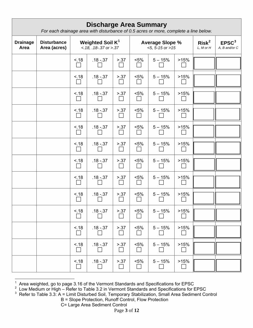
Discharge Area Summary For each drainage area with disturbance of 0.5 acres or more, complete a line below.
Drainage Area
Disturbance Area (acres)
Weighted Soil K1 <.18, .18-.37 or >.37
Average Slope % <5, 5-15 or >15
Risk2 L, M or H
EPSC3 A, B and/or C
<.18
.18 -.37
>.37
<5%
5 – 15%
>15%
<.18
.18 -.37
>.37
<5%
5 – 15%
>15%
<.18
.18 -.37
>.37
<5%
5 – 15%
>15%
<.18
.18 -.37
>.37
<5%
5 – 15%
>15%
<.18
.18 -.37
>.37
<5%
5 – 15%
>15%
<.18
.18 -.37
>.37
<5%
5 – 15%
>15%
<.18
.18 -.37
>.37
<5%
5 – 15%
>15%
<.18
.18 -.37
>.37
<5%
5 – 15%
>15%
<.18
.18 -.37
>.37
<5%
5 – 15%
>15%
<.18
.18 -.37
>.37
<5%
5 – 15%
>15%
<.18
.18 -.37
>.37
<5%
5 – 15%
>15%
<.18
.18 -.37
>.37
<5%
5 – 15%
>15%
<.18
.18 -.37
>.37
<5%
5 – 15%
>15%
Page 3 of 12
1 Area weighted, go to page 3.16 of the Vermont Standards and Specifications for EPSC 2 Low Medium or High – Refer to Table 3.2 in Vermont Standards and Specifications for EPSC 3 Refer to Table 3.3: A = Limit Disturbed Soil, Temporary Stabilization, Small Area Sediment Control
B = Slope Protection, Runoff Control, Flow Protection C= Large Area Sediment Control
Page 4 of 12
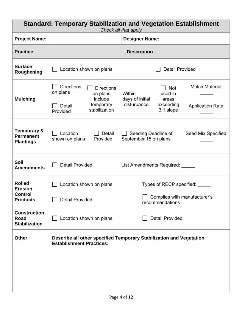
Standard: Temporary Stabilization and Vegetation Establishment
Check all that apply
Project Name: Designer Name:
Practice Description
Surface Roughening Location shown on plans Detail Provided
Mulching
Directions on plans
Directions on plans include
temporary stabilization
Within _____ days of initial disturbance
Not used in areas
exceeding 3:1 slope
Mulch Material: _____
Detail Provided
Application Rate: _____
Temporary & Permanent Plantings
Location shown on plans
Detail Provided
Seeding Deadline of September 15 on plans
Seed Mix Specified:_____
Soil Amendments Detail Provided List Amendments Required: _____
Rolled Erosion Control Products
Location shown on plans Types of RECP specified: _____
Detail Provided Complies with manufacturer’s recommendations
Construction Road Stabilization
Location shown on plans Detail Provided
Other
Describe all other specified Temporary Stabilization and Vegetation Establishment Practices:
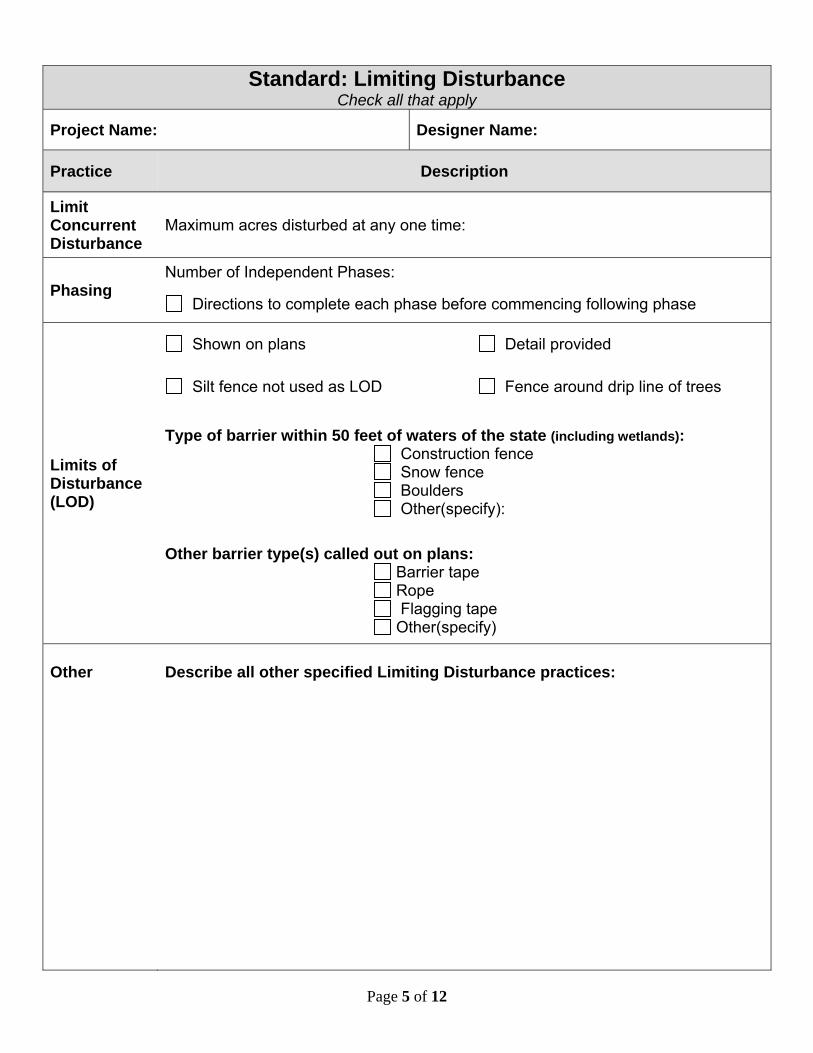
Standard: Limiting Disturbance Check all that apply
Project Name: Designer Name:
Practice Description
Limit Concurrent Disturbance
Maximum acres disturbed at any one time:
Number of Independent Phases: Phasing
Directions to complete each phase before commencing following phase
Limits of Disturbance (LOD)
Shown on plans Detail provided
Silt fence not used as LOD Fence around drip line of trees
Type of barrier within 50 feet of waters of the state (including wetlands):
Construction fence Snow fence Boulders Other(specify):
Other barrier type(s) called out on plans:
Barrier tape Rope Flagging tape Other(specify)
Other
Describe all other specified Limiting Disturbance practices:
Page 5 of 12
Page 6 of 12
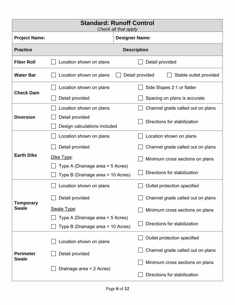
Standard: Runoff Control
Check all that apply
Project Name: Designer Name:
Practice Description
Fiber Roll Location shown on plans Detail provided
Water Bar Location shown on plans Detail provided Stable outlet provided
Check Dam Location shown on plans Side Slopes 2:1 or flatter
Detail provided Spacing on plans is accurate
Diversion
Location shown on plans Channel grade called out on plans
Detail provided Directions for stabilization
Design calculations included
Earth Dike
Location shown on plans Location shown on plans
Detail provided Channel grade called out on plans
Dike Type:
Type A (Drainage area < 5 Acres)
Type B (Drainage area < 10 Acres)
Minimum cross sections on plans
Directions for stabilization
Temporary Swale
Location shown on plans Outlet protection specified
Detail provided Channel grade called out on plans
Swale Type:
Type A (Drainage area < 5 Acres)
Type B (Drainage area < 10 Acres)
Minimum cross sections on plans
Directions for stabilization
Perimeter Swale
Location shown on plans Outlet protection specified
Detail provided Channel grade called out on plans
Drainage area < 2 Acres) Minimum cross sections on plans
Directions for stabilization
Page 7 of 12
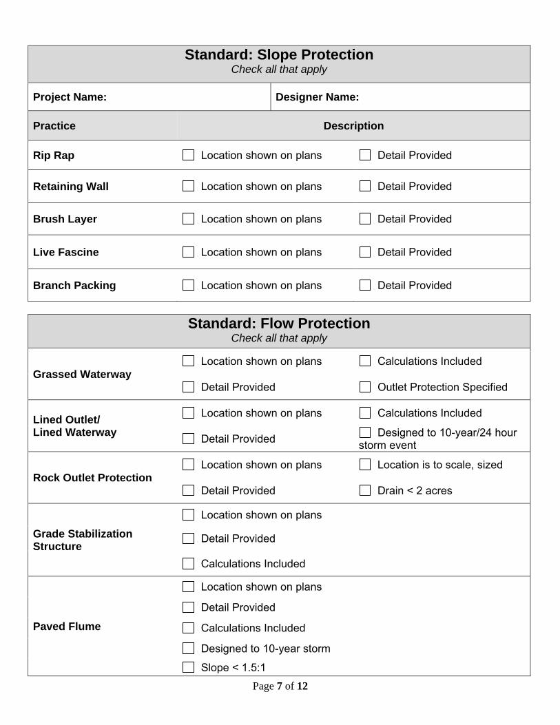
Standard: Slope Protection
Check all that apply
Project Name: Designer Name:
Practice Description
Rip Rap Location shown on plans Detail Provided
Retaining Wall Location shown on plans Detail Provided
Brush Layer Location shown on plans Detail Provided
Live Fascine Location shown on plans Detail Provided
Branch Packing Location shown on plans Detail Provided
Standard: Flow Protection
Check all that apply
Grassed Waterway Location shown on plans Calculations Included
Detail Provided Outlet Protection Specified
Lined Outlet/ Lined Waterway
Location shown on plans Calculations Included
Detail Provided Designed to 10-year/24 hour storm event
Rock Outlet Protection Location shown on plans Location is to scale, sized
Detail Provided Drain < 2 acres
Grade Stabilization Structure
Location shown on plans
Detail Provided
Calculations Included
Paved Flume
Location shown on plans
Detail Provided
Calculations Included
Designed to 10-year storm
Slope < 1.5:1
Page 8 of 12
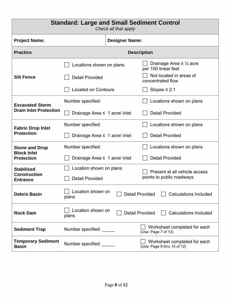
Standard: Large and Small Sediment Control
Check all that apply
Project Name: Designer Name:
Practice Description
Silt Fence
Locations shown on plans Drainage Area ≤ ¼ acre per 100 linear feet
Detail Provided Not located in areas of concentrated flow
Located on Contours Slopes ≤ 2:1
Excavated Storm Drain Inlet Protection
Number specified: Locations shown on plans
Drainage Area ≤ 1 acre/ inlet Detail Provided
Fabric Drop Inlet Protection
Number specified: Locations shown on plans
Drainage Area ≤ 1 acre/ inlet Detail Provided
Stone and Drop Block Inlet Protection
Number specified: Locations shown on plans
Drainage Area ≤ 1 acre/ inlet Detail Provided
Stabilized Construction Entrance
Location shown on plans Present at all vehicle access
points to public roadways Detail Provided
Debris Basin Location shown on plans Detail Provided Calculations Included
Rock Dam Location shown on plans Detail Provided Calculations Included
Sediment Trap Number specified: _____ Worksheet completed for each (Use: Page 7 of 12)
Temporary Sediment Basin Number specified: _____ Worksheet completed for each
(Use: Page 8 thru 10 of 12)
Page 9 of 12
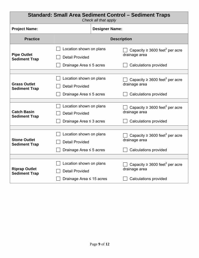
Standard: Small Area Sediment Control – Sediment Traps Check all that apply
Project Name: Designer Name:
Practice Description
Pipe Outlet Sediment Trap
Location shown on plans Capacity ≥ 3600 feet3 per acre drainage area Detail Provided
Drainage Area ≤ 5 acres Calculations provided
Grass Outlet Sediment Trap
Location shown on plans Capacity ≥ 3600 feet3 per acre drainage area Detail Provided
Drainage Area ≤ 5 acres Calculations provided
Catch Basin Sediment Trap
Location shown on plans Capacity ≥ 3600 feet3 per acre drainage area Detail Provided
Drainage Area ≤ 3 acres Calculations provided
Stone Outlet Sediment Trap
Location shown on plans Capacity ≥ 3600 feet3 per acre drainage area Detail Provided
Drainage Area ≤ 5 acres Calculations provided
Riprap Outlet Sediment Trap
Location shown on plans Capacity ≥ 3600 feet3 per acre drainage area Detail Provided
Drainage Area ≤ 15 acres Calculations provided
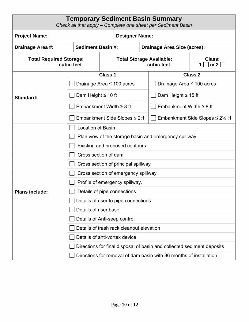
Temporary Sediment Basin Summary Check all that apply – Complete one sheet per Sediment Basin
Project Name: Designer Name:
Drainage Area #: Sediment Basin #: Drainage Area Size (acres):
Total Required Storage: __________ cubic feet
Total Storage Available: __________ cubic feet
Class: 1 or 2
Standard:
Class 1 Class 2
Drainage Area ≤ 100 acres Drainage Area ≤ 100 acres
Dam Height ≤ 10 ft Dam Height ≤ 15 ft
Embankment Width ≥ 8 ft Embankment Width ≥ 8 ft
Embankment Side Slopes ≤ 2:1 Embankment Side Slopes ≤ 2½ :1
Location of Basin
Plan view of the storage basin and emergency spillway
Existing and proposed contours
Cross section of dam
Cross section of principal spillway
Cross section of emergency spillway
Profile of emergency spillway.
Page 10 of 12
Plans include: Details of pipe connections
Details of riser to pipe connections
Details of riser base
Details of Anti-seep control
Details of trash rack cleanout elevation
Details of anti-vortex device
Directions for final disposal of basin and collected sediment deposits
Directions for removal of dam basin with 36 months of installation
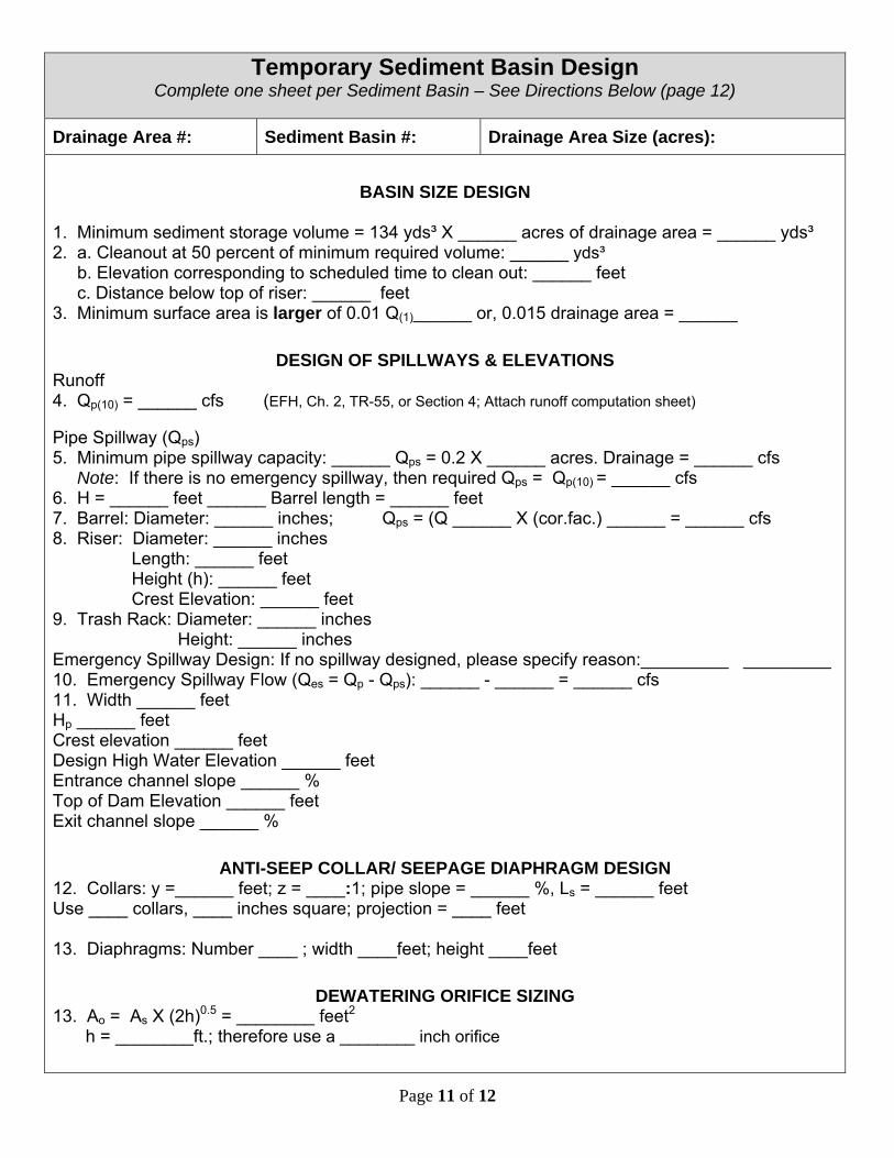
Temporary Sediment Basin Design Complete one sheet per Sediment Basin – See Directions Below (page 12)
Drainage Area #: Sediment Basin #: Drainage Area Size (acres):
BASIN SIZE DESIGN 1. Minimum sediment storage volume = 134 yds³ X ______ acres of drainage area = ______ yds³ 2. a. Cleanout at 50 percent of minimum required volume: ______ yds³ b. Elevation corresponding to scheduled time to clean out: ______ feet c. Distance below top of riser: ______ feet 3. Minimum surface area is larger of 0.01 Q(1)______ or, 0.015 drainage area = ______
DESIGN OF SPILLWAYS & ELEVATIONS Runoff 4. Qp(10) = ______ cfs (EFH, Ch. 2, TR-55, or Section 4; Attach runoff computation sheet) Pipe Spillway (Qps) 5. Minimum pipe spillway capacity: ______ Qps = 0.2 X ______ acres. Drainage = ______ cfs Note: If there is no emergency spillway, then required Qps = Qp(10) = ______ cfs 6. H = ______ feet ______ Barrel length = ______ feet 7. Barrel: Diameter: ______ inches; Qps = (Q ______ X (cor.fac.) ______ = ______ cfs 8. Riser: Diameter: ______ inches
Length: ______ feet Height (h): ______ feet Crest Elevation: ______ feet
9. Trash Rack: Diameter: ______ inches Height: ______ inches
Emergency Spillway Design: If no spillway designed, please specify reason:_________ _________ 10. Emergency Spillway Flow (Qes = Qp - Qps): ______ - ______ = ______ cfs 11. Width ______ feet Hp ______ feet Crest elevation ______ feet Design High Water Elevation ______ feet Entrance channel slope ______ % Top of Dam Elevation ______ feet Exit channel slope ______ %
ANTI-SEEP COLLAR/ SEEPAGE DIAPHRAGM DESIGN 12. Collars: y =______ feet; z = ____:1; pipe slope = ______ %, Ls = ______ feet Use ____ collars, ____ inches square; projection = ____ feet 13. Diaphragms: Number ____ ; width ____feet; height ____feet
DEWATERING ORIFICE SIZING 13. Ao = As X (2h)0.5 = ________ feet2
h = ________ft.; therefore use a ________ inch orifice
Page 11 of 12
Page 12 of 12
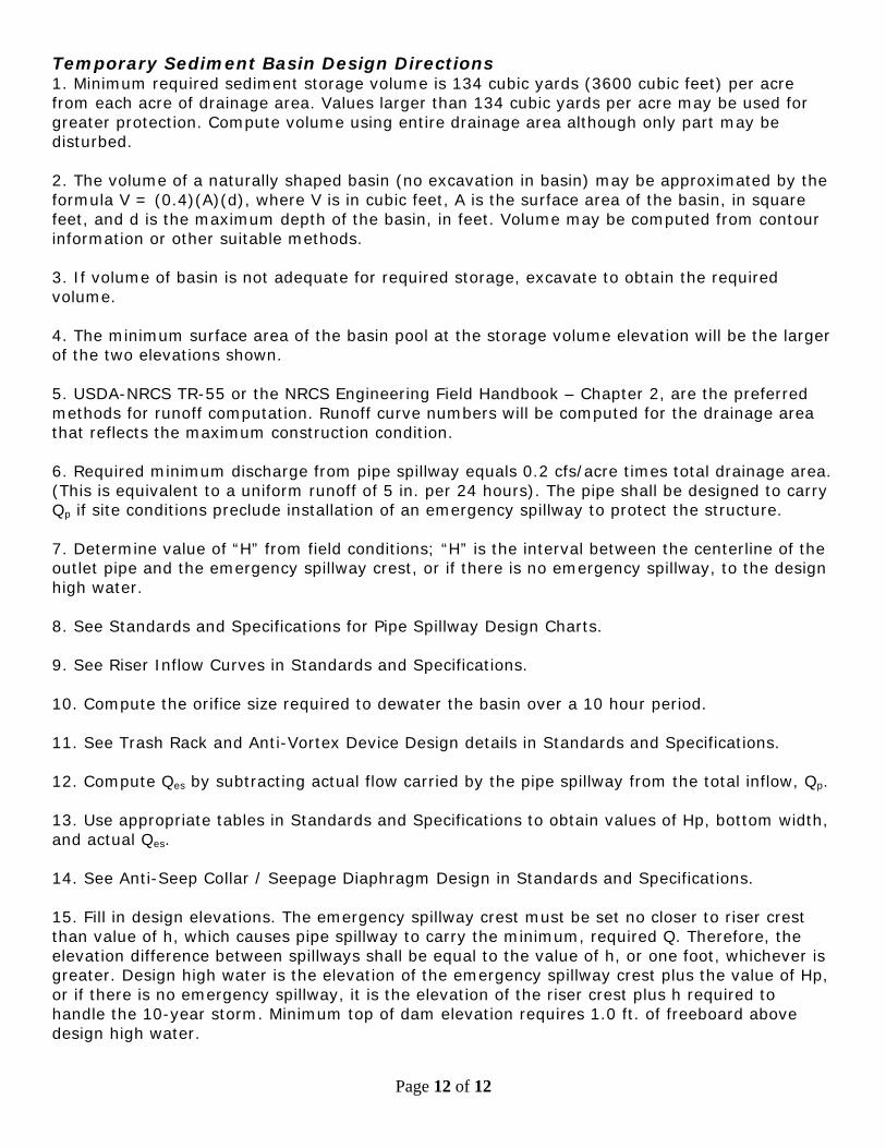
Temporary Sediment Basin Design Directions 1. Minimum required sediment storage volume is 134 cubic yards (3600 cubic feet) per acre from each acre of drainage area. Values larger than 134 cubic yards per acre may be used for greater protection. Compute volume using entire drainage area although only part may be disturbed. 2. The volume of a naturally shaped basin (no excavation in basin) may be approximated by the formula V = (0.4)(A)(d), where V is in cubic feet, A is the surface area of the basin, in square feet, and d is the maximum depth of the basin, in feet. Volume may be computed from contour information or other suitable methods. 3. If volume of basin is not adequate for required storage, excavate to obtain the required volume. 4. The minimum surface area of the basin pool at the storage volume elevation will be the larger of the two elevations shown. 5. USDA-NRCS TR-55 or the NRCS Engineering Field Handbook – Chapter 2, are the preferred methods for runoff computation. Runoff curve numbers will be computed for the drainage area that reflects the maximum construction condition. 6. Required minimum discharge from pipe spillway equals 0.2 cfs/acre times total drainage area. (This is equivalent to a uniform runoff of 5 in. per 24 hours). The pipe shall be designed to carry Qp if site conditions preclude installation of an emergency spillway to protect the structure. 7. Determine value of “H” from field conditions; “H” is the interval between the centerline of the outlet pipe and the emergency spillway crest, or if there is no emergency spillway, to the design high water. 8. See Standards and Specifications for Pipe Spillway Design Charts. 9. See Riser Inflow Curves in Standards and Specifications. 10. Compute the orifice size required to dewater the basin over a 10 hour period. 11. See Trash Rack and Anti-Vortex Device Design details in Standards and Specifications. 12. Compute Qes by subtracting actual flow carried by the pipe spillway from the total inflow, Qp. 13. Use appropriate tables in Standards and Specifications to obtain values of Hp, bottom width, and actual Qes. 14. See Anti-Seep Collar / Seepage Diaphragm Design in Standards and Specifications. 15. Fill in design elevations. The emergency spillway crest must be set no closer to riser crest than value of h, which causes pipe spillway to carry the minimum, required Q. Therefore, the elevation difference between spillways shall be equal to the value of h, or one foot, whichever is greater. Design high water is the elevation of the emergency spillway crest plus the value of Hp, or if there is no emergency spillway, it is the elevation of the riser crest plus h required to handle the 10-year storm. Minimum top of dam elevation requires 1.0 ft. of freeboard above design high water.


![Bureau of Watershed Management Regulatory Proposal Chapter 102 [Erosion and Sediment Control] Erosion, Sediment and Stormwater Management February 21,](https://img.pdfslide.net/doc/110x75/5697bfd61a28abf838cae07f/bureau-of-watershed-management-regulatory-proposal-chapter-102-erosion-and.jpg)