Embed Size (px)
Citation preview
Errors & Inaccuracies in Repositioning of Archaeological Sites
S. Topouzi Laboratory of Geophysical - Satellite Remote Sensing &Archaeo-environment
Institute of Mediterranean Studies - Foundation of Research & Technology (F.O.R.T.H.) Melissinou & Nik. Foka 130, PO. Box 119
GR-74100 Rethymnon, Crete. Greece Phone: +30831-56627 - Fax: +30831-25810 - E-mail: [email protected] or [email protected]
A. Tripolitsiotis Laboratory of Geodesy and Geomatics Engineering
Department of Mineral Resources Engineering Technical University of Crete
GR-73100 Chania, Crete, Greece Phone: +30821-37429 - Fax: +30821-37476 - E-mail: [email protected] or [email protected]
A. Sarris Laboratory of Geophysical - Satellite Remote Sensing &Archaeo-environment
Institute of Mediterranean Studies - Foundation of Research & Technology (F.O.R.T.H.) Melissinou & Nik. Foka 130, PO. Box 119
v GR-74100 Rethymnon, Crete. Greece Hione:+30831-56627 - Fax:+30831-25810 - E-mail: [email protected]
\ S. Mertikas Laboratory of Geodesy and Geomatics ^•
Department of Mineral Resources Engineering Technical University of Crete
GR-73100 Chania, Crete, greece •' Phone:+30821-37429-Fax:+30821-37476-E-mail: [email protected]
S. Soetens Laboratory of Geophysical - Satellite Remote Sensing & Archaeo-environment
Institute of Mediterranean Studies - Foundation of Research & Technology (F.O.R.T.H.) Melissinou & Nik. Foka 130, PO. Box 119
GR-74100 Rethymnon, Crete, Greece Phone:+30831-56627 - Fax:+30831-25810 - E-mail: [email protected].
Abstract: In archaeological sui-veys and excavations, positioning and mapping of sites and monuments is essential to studies related to settlement pattern, viewshed analysis as well as cultural resource management. Various methods and techniques have been used in the past for the mapping of sites according to the technological means that were available at each time. These methods had a variable degree of accuracy, creating a number of problems in the repositioning of archaeological sites today.
The errors and inaccuracies of the past mapping techniques are discussed and they are compared with the latest developments of the GPS technology. The various GPS geodetic surveying techniques employed today are here addressed, along with a statistical analysis of the position data, as a function of time and distance.
Problems related to the transformation of geodetic coordinates from one reference system to another and the geometric registration ofaerial and satellite imagery are addressed, as well as the effects of error propagation in the analysis of viewshed or topographic slope.
Keywords : GPS, differential processing, GIS, vie^vshed analysis.
417
Introduction
Even before the beginning of the first archaeological excavations, travellers designed and recorded on maps the remnants of the visible ancient monuments, which they met in their route. The purpose was to provide the prospective researchers a way to identify and reposition the archaeological sites. The methods employed in the past were able to record the approximate location of the sites in a very relative way. Problems in accuracy and consistency, both in terms of coordinates and map scale, are obvious today.
Though positioning and mapping of sites was always regarded as a necessity, there are not many things that have changed in the corresponding approach of the archaeologists until the very recent years. The methods used were more or less similar to those of the travellers : a compass, a pencil and a paper map.
Later on the use of theodolite upgraded archaeological mapping and cartography. A theodolite provides coordinates of a site by measuring horizontal and vertical angles from a base station. Of similar use is the electromagnetic distance measurement (EDM), invented in the mid-20'' century. The latter made it possible to measure distances as accurately and easily as theodolite, by electronically timing the passage of radiation over the distance to be measured. Although the above techniques provided advantages in local scale mapping of sites and monuments, problems arose in large-scale extensive mapping of sites that require a visual contact between the ob- servation stations and the recording of coordinates in local reference datums.
Traditional surveying techniques commonly use a total geodetic station with a theodolite, an Electronic Distance Measuring (EDM) device and several reflectors to determine monument coordinates. The reflectors are mounted on rods while intervisibility between the surveying instrument and the reflectors should always be guaranteed. Errors of determined coordinates are in that case proportional to the separation distance and hence the larger the spacing, the larger the surveying error.
Although the use of theodolites and EDMs is rather easy and inexpensive, these instruments have only occasionally been used to record and map survey sites (MacDonald - Rapp 1972, Whitley 1999). The more common method of recording sites in the course of a surface survey is by sketching the surveyed areas on 1:5000 scale maps or on aerial photos and then adding spots to represent the sites that have been found. Information about the size, the location and the surrounding area is usually recorded in the survey notebooks (Macready - Tompson 1985; Wright et al. 1985,1990; Fish-Kowalewski 1990;Alcock 1991; Hayden et al. 1992; Watrous 1993; Jameson - Runnels - van Andel 1994; Haggis 1996; Branigan 1998).
Due to the subjectivity of the descriptions of various research- ers and the recent changes of the environmental conditions (both by natural or anthropogenic causes), repositioning of sites based on a survey published report has been proven a difficult, if not impossible, task. On the other hand the accurate relocation and mapping of sites has become an essential module
in archaeological research, whether it is related to topographic studies or settlement pattern analysis and cultural resource management.
An alternative methodology, which includes satellite-based positioning technology is offered by the Global Positioning System (GPS) (Federal Radionavigation Plan, 1999).
The Global Positioning System
The most up-to-date way of specifying the horizontal coordinates of a site, so as its elevation, is by using the Global Positioning System (GPS).
GPS is a satellite-based technology developed by the U.S. De- partment of Defense. It provides accurate, continuous, three- dimensional position and velocity information to users with appropriate receivers. GPS also disseminates a form of Coordinated Universal Time (UTC).
The satellite constellation consists of 24 satellites in 6 orbital planes, with 4 satellites in each plane. Each satellite transmits ranging codes and navigation data on two frequencies (L1 = 1575.42 MHz and L2 = 1227.6 MHz). The basic concept of the GPS estimation of coordinates is the measurement of the distance of a point on the surface of the Earth from four or more satellites, using a receiver.
In any case, the constellation of the satellites is planned in a way to provide at least four satellites in good geometric posi- tion 24 hours per day at any position on earth. The available satellites over a location can even reach the number often.
Using a network of five worldwide monitoring stations, naviga- tion data are uploaded to satellites. Thus, a user can accurately determine the position, velocity and time of his receiver, by measuring the one-way time of arrival (TOA) to the satellites. On July 17,1995, the US Department of Defense announced the full operational capability of the GPS system.
Observation Techniques
Until some time ago, recording with a single GPS receiver provided an accuracy of the order of plus or minus 100m, because it only had the ability to use one frequency. After the recent release of the second frequency, it is estimated that measurements will have an even better accuracy, even with only one receiver. Still, some applications demand even a sub-centimetre accuracy. In that case, the satellite positioning techniques require at least two receivers to measure the GPS satellite signals simultaneou- sly. A reference station is located at a fixed point, within the area of interest, while the second receiver is set on another point (roving station), whose coordinates are to be establis- hed. For post processing applications, the actual observations from the reference station are provided to the roving station. The positions of the roving station are then computed through special data reduction software. These GPS surveying techniques are briefly described below. Figure 1 presents the concept of modem surveying techniques (Hofmann-Wellenhof, et al., 1994).
418
Relative Static Positioning is the classical GPS surveying technique, where the reference, as well as the secondary, stations are set up over static points, to measure satellite signals for long observation sessions (ranging from 30 min to several hours to days). The length of each observation session is a fimction of the measured length of the baseline between the two stations, the number of the satellites being tracked and the satellite geometry. Static positioning determines the three-dimensional vector from the base to the secondary station and provides the most accurate and reliable results, in the order of millimeters and sub-millimeters (fig. 2).
To measure as many baselines as possible, in the briefest ob- servation sessions (i.e., minutes or even seconds) and to obtain results while the secondary station is in motion, several mo- dem GPS surveying techniques have been developed recently. These are the Rapid Static, the Reoccupation, the Stop&Go and the Kinematic positioning techniques. All these techniques require special hardware and software, as well as specific field procedures.
The Rapid Static technique requires shorter observation periods than the classical static GPS surveying, typically in the order of 5 min to 20 min, depending on the baseline length and the number of satellites being tracked. For example, for a baseline of less than 5 km and tracking 6 or more satellites, the required observation time is about 5 min with accuracies in the order of one centimeter.
The Reoccupation positioning technique is faster than the classical static one and requires observation sessions of a few minutes at each secondary station, but collected about one or more hours apart. That means that, while the base station remains stationary, the roving receiver must reoccupy the same secondary point one or more hours later to allow for changes in satellite geometry, in order to achieve centimeter accuracies. It should be noted that the roving receiver could be switched off between revisiting sessions. In this case, no special hardware is needed but only appropriate software for data post-proces- sing.
The Stop&Go surveying is a semi-kinematic technique. The roving receiver has to stop over stationary points to collect a few minutes of data in order to determine their coordinates. In addition, it continues to move while tracking GPS satellites from one site to the next. The trajectory of the roving antenna is not of interest here but only the stationary points. Special initialization field procedures are necessary before a Stop&Go survey begins and the technique may not allow signal disruptions, while moving from site to site (i.e., going under a bridge or thick foliage). Accuracies of 1 to 2 centimeters can be obtained with a Stop&Go procedure.
True kinematic GPS procedures attaining accuracies of centime- ters for the moving antenna have been under development recently. To avoid re-initialization of field procedures, as required in the Stop&Go method, several sophisticated software programs (e.g., on-the-fly ambiguity resolution techniques) are being developed to secure and account for GPS signal interruptions that may occur during motion.
Real-time kinematic (RTK) is another GPS procedure, where positioning accuracies of the order of centimeters can be achieved in real time. It requires, however, a radio communication link (such as VHP, UHF etc.) to transmit GPS correction data, from the reference receiver to the roving receivers (fig. 3).
Advantages and disadvantages in the use of GPS for archaeological sites positioning
Total geodetic stations composed of mechanical, optical and electronic components have not undergone the dramatic price reduction that the computer market is experiencing these days. The average cost of a total geodetic station never fell below the range of US $ 10,000 to $20,000. On the other hand, GPS receivers, composed mainly of electronic parts, have experienced a tremendous price reduction similar to that of the computer market; starting with a price of $100,000 in 1980, and falling down to the $10,000-$ 15,000 range in 2001, for basic models measuring phase. It should be noted, however, that for accurate relative position determination, a pair of GPS receivers is needed, thus doubling the cost of the GPS instrumentation.
GPS technology, however, has several advantages over conventional terrestrial techniques in terms of instrument cost, ease of operation and productivity. It can also be used easily as a data capture tool for Geographic Information Systems (GIS) because the data provided are digital.
Further, this GPS technology has the following advantages over conventional terrestrial surveying methods:
It requires no intervisibility between GPS stations, The coordinates are recorded in a global reference system (the Worid Geodetic System '84 - WGS'84), which is independent of local reference datums. All GPS operations are weather independent and can work around the clock. The positioning is carried out accurately and quickly, GPS has the ability to measure simultaneously the three components of coordinate vector (i.e., horizontal position and height) of any point on the surface of the earth.
Nevertheless, GPS surveying has disadvantages over the conventional terrestrial techniques:
The receivers can not be used in a subterranean survey (such as tombs, caves, tunnels etc.) or under trees, because there is not visual contact with the satellites. Frequently the results, being in a global reference system ( WGS '84), have to be transformed in the local datums, an act that can often cause transformation inaccuracies. The GPS elevations are not orthometric. which means that they are not measured from the surface of the sea. The cost of the receivers is high, for a moderate user. Training and experience is required in order to use the receivers.
419
GPS surveying - Methodology
During the last four years, the Laboratory of Geophysical - Satellite Remote Sensing and Archaeo-environment of the In- stitute of Mediterranean Studies - F.O.R.T.H. has been involved in a number of GIS projects, involving GPS mapping of archaeological sites. In one of the projects, dealing with the construction of a digital archaeological registry of Lasithi. in East Crete, more than 200 sites were positioned and mapped through the use of GPS techniques. A number of ground control points (GCPs) were also recorded to be used for the geometric rectification and registration of aerial and satellite images.
After retrieving information (from the published bibliography related to the cultural resources of the region), a total of 972 sites were registered in a database, which contained, among other, information related to the general location of the sites, their type and chronology, environmental data etc. The next step was to position the sites with accurate coordinates in or- der to map and correlate them with the rest cartographic mate- rial, such as digitized maps and satellite images. Two state-of- the-art geodetic receivers (Ashtech Z-12 double frequency receivers) were deployed to relocate the archaeological sites.
Still finding the sites was not always an easy task. Relaying on the published plans of the survey reports, some sites were difficult o impossible to be found again. That fact made once again clear the need of accurate positioning of the sites.
Forthose sites found, data were collected using the static diffe- rential positioning, in order to achieve a higher degree of accuracy. The base station was connected to a Choke-ring antenna and to both a battery and the electric power, so as to prevent loss of data in case of power failure, and took measurements every 30 seconds for the most part of the day, while the second receiver was moving at the sites of interest.
The second receiver (Rover) was used in the field, connected to a geodetic antenna (usually placed on a tripod) and to a battery. The receiver recorded for a period of approximately 15 minutes, locating 4 to 10 satellites each time. For each point recorded, the proper parameters were inserted in the device, while the signal was stored with a different distinctive 4-digit code name.
The selection of points to be recorded, varied according to the case. In areas where the archaeological remains were visible, an effort was made to describe the perimeter of the site, by recording several points of it (fig.4). In cases where topographic plans of the site existed, distinctive points of the plans were recorded and assigned on them. In sites with undefined boundaries, a couple of points were recorded in order to define the size of them. One measurement was recorded for tombs, in the entrance of caves or at sites with indefinite evidence of archeological remains (but with confirmed testimonies of existence).
Besides the archaeological sites, a number of ground control points (GCPs) were established for georeference and registration of the images to the national coordinate system. Thus, the points were chosen in such places so they would be visible in both air photos and satellite images.
Processing of the data was conducted daily, in order to keep track of the accuracy and the measurement quality. Every measurement was processed and corrected according to the data recorded by the base, so as to obtain the minimum percentage of error. The coordinates of the base were corrected in the beginning of each survey, taking 1 hour measurements with the static positioning technique and by using the known coordinates of a close-by army datum point.
The coordinates of the sites were recorded in both the WGS'84 and the EGSA'87 reference systems. While WGS'84 is the reference system used from the GPS. EGSA'87 is the system used from the National Cadastre of Greece. Processing was followed by exporting the coordinates in spreadsheets (excel format) in order to import them in the database of the Geographic Information System.
On average the accuracy of position determination was found to be less than 10 centimetres. The accuracy of the GPS data was tested by checking misclosures of datum points of known coordinates, established by the Greek military.
Statistical processing - Errors and suggestions
The recorded GPS points (over 350) were subjected to statistical processing in order to determine the relation among the distance between the rover receiver and the base station, the recording time and the deviation in the accuracy of estimating the coordinates (x, y, z) of a site.
After sorting the deviation values for x (Easting), y (Northing) and z (Altitude), the following accuracy and distance classes were created :
Accuracy in mm
0-5 5.1-10 10.1-15 15,1-20 20.1 <
Dixlance in m «-2000 2000.1-5000 5U00.1-
10000
lOOCXI.I-
15000
15000.1-
2mm)
200(X).I <
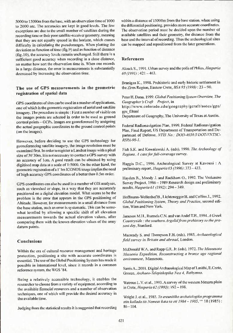
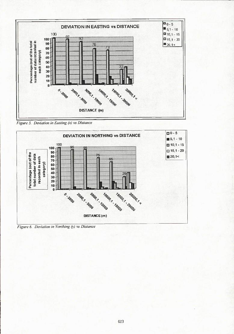
The percentage of points assigned to each accuracy class was appointed to the corresponding distance class. The results follow in figures 5,6 and 7.
Obviously the accuracy, when recording within a distance of 0 to 2000m from the base station, is quite impressive in all axes, reaching the percentage of 95 to 100. Furthermore it remains in good levels as to the Easting and Northing until the distance of 20000m, a fact that proves the precision of the GPS equipment. The relatively higher error in altitude is due to the known defect of the GPS in positioning heights within sort periods of obser- vation, a fact that can be outweighed when assigning to the measurements the correct geoid.
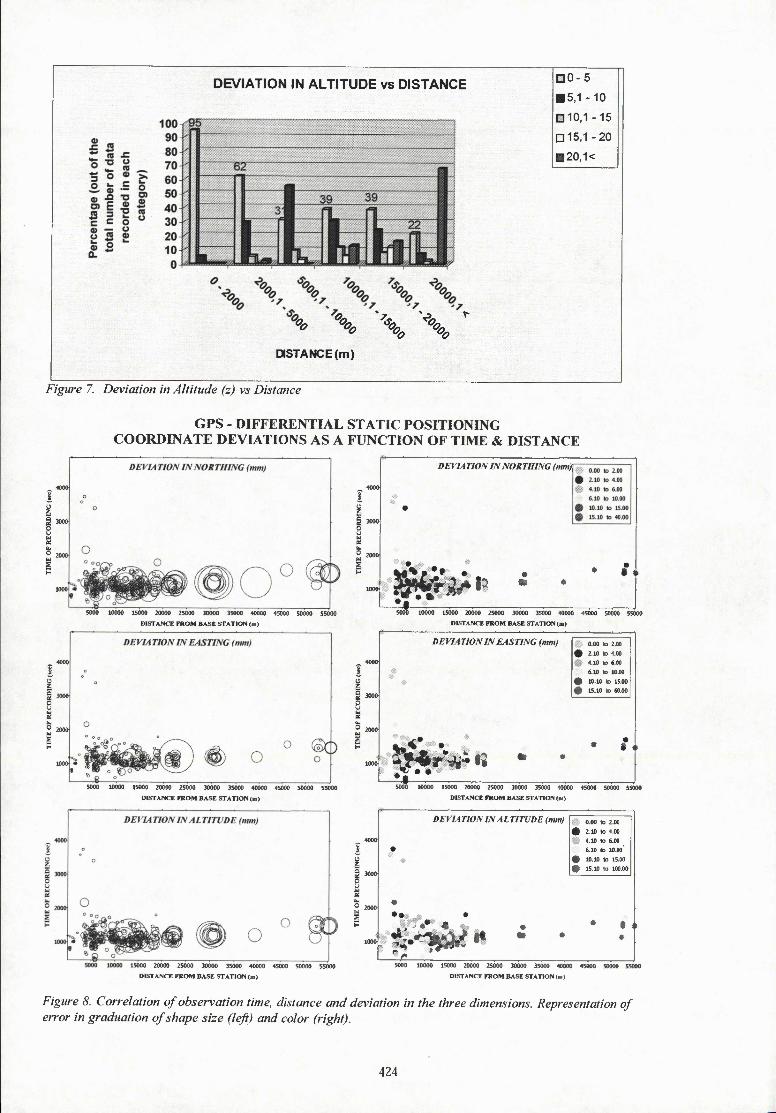
When the factor of time was considered together with distance, accuracy was divided in smaller classes : 0 - 2,2.1 - 4.4.1 - 6. 6.1 - 10,10.1-15.15-40 (60 for Easting and 100 for Altitude). Figure 8 represents the error in accuracy as a function of the distance in two ways : by graduation of shape size and by different colors.
The large concentration of GPS points is within the distance of
420
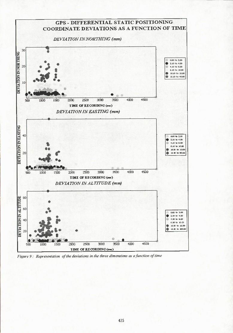
5000 to 1 SOGOiTi from the base, with an observation time of 1000 to 2000 sec. The accuracies are kept in good levels. The few exceptions are due to the small number of satellites during the recording time or their poor satellite-receiver geometry, meaning that they are not equally spaced in the horizon, which causes difficulty in calculating the pseudoranges. When plotting the deviation as function of time (fig.9) and as function of distance (fig. 10). the accuracy levels remain unchanged. Still there is a sufficient good accuracy when recording in a close distance, no matter how sort the observation time is. When one records in a large distance, the error in measurements is substantially decreased by increasing the observation time.
The use of GPS measurements in the geometric registration of spatial data
GPS coordinates of sites can be used in a number of applications, one of which is the geometric registration of aerial and satellite imagery. The procedure is simple : First a number of visible on the images points are selected in order to be used as ground control points - GCPs. Images are georeferenced by assigning the actual geographic coordinates to the ground control points (on the images).
However, before deciding to use the GPS technology for georeferencing satellite imagery, the image resolution must be examined first. In order to register a Landsat image with a pixel size of 30'30m, it is not necessary to contact a GPS survey with an accuracy of 1cm. A good result can be obtained by using digitised map data at a scale of 1:5000. On the other hand, the geometric registration of a I'lm ICONOS image implies the need of high accuracy GPS coordinates of a better than 0.5m order.
GPS coordinates can also be used in a number of GIS analyses, such as viewshed or slope, in a way that they are accurately positioned on a digital elevation model. What seems to be the problem is the error that appears in the GPS positioning of Altitude. However, for measurements in a small distance from the base station, such an error is systematic. This can be some- what levelled by allowing a specific shift of all elevation measurements towards the actual elevation values, after comparing them with the known elevation values of the army datum points.
Conclusions
Within the era of cultural resource management and heritage protection, positioning a site with accurate coordinates is essential. The use of the Global Positioning System has made it possible in intemational level, since it records in a common reference system, the WGS '84.
Being a relatively accessible technology, it enables the researcher to choose from a variety of equipment, according to the available financial resources and a number of observation techniques, one of which will provide the desired accuracy in the available time.
Judging from the statistical results it is suggested that recording
within a distance of 15000m from the base station, when using the differential positioning, provides more accurate coordinates. The observation period must be decided upon the number of available satellites and their geometry, the distance from the base and the interval of recording. Thus the archeological sites can be mapped and repositioned from the later generations.
References
Alcock S., 1991. Urban survey and the polis of Phlius, Hesperia 60 (1991)-.421-463.
Branigan K., 1998. Prehistoric and eariy historic settlement in the Ziros Region, Eastern Crete, BSA 93 (1998) : 23 - 90.
Peter H.Dana, 1999. Global Positioning System Overview, The Geographer's Craft Project, in http://www.colorado.edu/geography/gcraft/notes/gps/ gpsfhtml Department of Geography, The University of Texas at Austin.
Federal Radionavigation Plan, 1999. Federal Radionavigation Plan, Final Report, US Department of Transportation and De- partment of Defense, NTIS No.: DOD-4650.5/DOT-VNTSC- RSPA-98-1.
Fish S.K. and Kowalewski A. (eds), 1990. The Archeology of Regions, A case for full-coverage survey.
Haggis D.C.. 1996. Archeological Survey at Kavousi : A preliminary report, Hesperia 65 (1996): 373-433.
Hayden B.. Moody J. and Rackham O.. 1992. The Vrokastro Survey Project. 1986 - 1989 Research design and preliminary results. Hesperia 61 (1992): 294 - 349.
Hoffmann-Wellenhof B.. Lichtenegger H. and Collins J., 1992. Global Positioning System, Theory and Practice, second edi- tion, Wien and New York.
Jameson M.H., Runnels C.N. and van Andel TH.. 1994. A Greek Countryside : the southern Argolid from prehistory to the pre- sent day, Stanford.
Macready S. and Thompson F.H. (eds), 1985. Archaeological field survey in Britain and abroad, London.
McDonald W.A. and Rapp GR. Jr. (eds), 1972. The Minnesota Messenia Expedition. Reconstructing a bronze age regional environment, Minnesota.
Sarris A.. 2001. Digital Archaeological Map of Lasithi, E.Crete, Greece, Archaeo-Telepiskopika Nea 4, Rethymno.
Watrous L. V. et al., 1993. A survey of the western Mesara plain in Crete, Hesperia 62 (1993) : 192 - 198.
Wright J. et al., 1985. To ereunitiko archaiologikoprogramma stin koilada tis Nemeas kata ta eti 1984-1985, '" 18 ( 1985) : 86-104.
421

Wright et al., 1990. The Nemea Valley Archaeological Project : A Whitley J. et al., 1999. Praisos IV: A preliminary report on the preliminary report,//csper/a 59 f/PPO): 579-645. 1993 and 1994 survey seasons, 55/4 94(1999): 205-247.
Figures
Base Station Line
Figure 3. Real Time Kinematic GPS
Figure 1. Modem GPS surveying techniques
Figure 4 Simultaneous mapping with GPS and EDM at Chalinomouri, E. Crete
Reference Station Secondary station Figure 2. Relative static positioning
422
DEVIATION IN EASTING vs DISTANCE
So?
£||
c » aj 0) 2 e £ 0) 3 a c
100 90 80 70 60 50 40 30 20 10 0
100 •('IM
,„ „„^. ^^ ^,„ ...
76 (
r J 1
32 PB 1 i 1 illJ rlJ
^^K. •i« ^^^^^^^ u [J lt. \ \ \ \ \ \
\ \ \
DISTANCE (m)
°0-5 •5,1-10 DlO.I - 15 ni5,1 - 20 •20.1<
Figure 5. Deviation in Easting (x) vs Distance
DEVIATION IN NORTHING vs DISTANCE
•^ m •O O
ö >- c
o) E » «5 = Î c = o » — o o S S I5
-<?^ -o.
DISTANCE (m)
• 0-5
• 5,1-10
a 10,1 -15 ni5,i -20 • 20,1<
Figure 6. Deviation in Northing (y) vs Distance
423
DEVIATION IN ALTITUDE vs DISTANCE
% % \ \
DISTANCE (m)
• 0-5
• 5,1 -10
1110,1 -15
ö 15,1-20
• 20,1<
Figure 7. Deviation in Altitude (z) vs Distance
GPS - DIFFERENTIAL STATIC POSITIONING COORDINATE DEVIATIONS AS A FUNCTION OF TIME & DISTANCE
5000 10000 15000 20000 25000 30000 35000 40000 45000 50000 5S000
DISTANCE FROM BASE STATION (•)
5000 10000 15000 20000 25000 30000 35000 40000 45000 50000 55000
DISTANCE FROM BASE STATION (•>
15000 20000 25000 30000 35000 40000 45000 50000 55000
DISTANCE FROM BASE STATION (m)
i i S 3000 O
DEVIA TION IN NORTHING (nun)
^^^i" • O
10000 15000 20000 25000 30000 35000 40000 45000 50000 55000
DICTANCE FROM BASE STATION (m>
DEVIA TiON /A EASTING {mm} 0.00 10 2.00
• 2.10 n 4.00 4.10 to 6.00 6.10 to 10.00
• lO.lO B 15.00
• 15.10 to 60.00
50iw 10000 15000 20000 25000 30000 35000 40000 45000 50000 55000
DISTANCE PROM BASE STATION (»)
DEVIATION IN ALmVDE (nun) 0.00 to 2.00
• 2.10 to 4.00 4.10 to 6.00 6.10 10 10.00
• 10.10 ID 15,00
• 15.10 to 100.00
ü 5000 10000 15000 20000 25000 30000 35000 40000 450OO 50000 55000
DISTANCE FROM BASE STATION (at)
Figure 8. Coirelation of observation time, distance and deviation in the three dimensions. Representation of error in graduation of shape size (lefi) and color (right).
424
GPS DIFFERENTIAL STATIC POSITIONING COORDINATE DEVIATIONS AS A FUNCTION OF TIME
DEVIATION IN NORTHING (mm)
500 1000 1500 2D00 2500 3000 3500 4000
TME OF RE CORDING (sec)
DEVIATION IN EASTING (mm)
4500
SCO 1000 1500 2D00 2500 3000 3500
TIME OF RE CORDING (sec)
DEVIA TION IN AL TITÜDE (mm)
4000 4500
IS.. OJOO to 2J00
« 2.)0 to .IJOO
SI 1.10 to 4«>
e.io «o woo
« MX» to iSOO
» 15 » to COJOO
oxo to 100
• 1.10 to 4.00
• 1.10 to e.00
&.10 to ».œ
• ia» to isoo
« IS.» to lOOOO
2000 2500 3000 3500
TIME OF RE CORDING fe«)
Figure 9 : Representation of the deviations in the three dimensions as a function of time
425
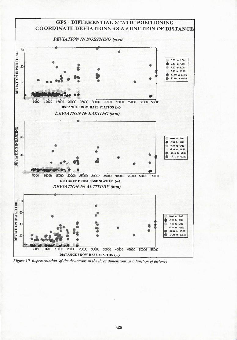
GPS - DIFFERENTIAL STATIC POSITIONING COORDINATE DEVIATIONS AS A FUNCTION OF DISTANCE
DEV/A TfON IN NORTHING (mm)
30 • • 4»-- •
—*•—•
• •
20 «
*
10'
> «
•
# 5000 1GÛ00 15000 20000 25000 30000 39000 40000 45000 50000 55000
DISTANCE FROM BASE STATION (m)
DEVIA TION IN EASTING (mm)
5000 10000 15000 20000 25000 30000 39000 40000 45000 50ÜOO
DISTANCE FROM BASE STATION (m)
DEVIA TION IN AL TTTUDE (mm)
5000
W 93-
5000 10000 15000 20000 25000 SOOCD 35000 40000 45000 50000 55000
DISTANCE FROM BASE STATION (m)
Q.QO lb 2.00
• i.lû 03 4 00
'•Vl tn £.00
fl.lO m lûûû
« 10.10 'H 15âQ
t 15.10 en MiÜÜ
0.00 (b 2.00
• 2.10 ta 4.00 4.10 tD 6.00
«10 <a IQJOO
« 10.10 w IîJOO
• 15.10 ta £0X10
Q.OO ta 2.00
• 2.10 u 4.00
4.10 !• 6.00
6.10 m lOJX
• 10 10 tn 15Û0
* 15.10 u> 100.00
Figure 10. Representation of the deviations in the three dimensions as a function of distance
426