Embed Size (px)
Citation preview

ES 201 168 V1.1.1 (1998-05)ETSI Standard
Corporate Networks (CN);Transmission characteristics of digital
Private Branch eXchanges (PBXs)

ETSI
ES 201 168 V1.1.1 (1998-05)2
ReferenceDES/CN-07001 (atc00icp.PDF)
KeywordsPABX, transmission, digital
ETSI
Postal addressF-06921 Sophia Antipolis Cedex - FRANCE
Office address650 Route des Lucioles - Sophia Antipolis
Valbonne - FRANCETel.: +33 4 92 94 42 00 Fax: +33 4 93 65 47 16
Siret N° 348 623 562 00017 - NAF 742 CAssociation à but non lucratif enregistrée à laSous-Préfecture de Grasse (06) N° 7803/88
[email protected]://www.etsi.fr
http://www.etsi.org
Copyright Notification
No part may be reproduced except as authorized by written permission.The copyright and the foregoing restriction extend to reproduction in all media.
© European Telecommunications Standards Institute 1998.All rights reserved.
ETSI
ES 201 168 V1.1.1 (1998-05)3
Contents
Intellectual Property Rights................................................................................................................................8
Foreword ............................................................................................................................................................8
1 Scope........................................................................................................................................................9
2 References................................................................................................................................................9
3 Definitions and abbreviations ................................................................................................................113.1 Definitions ....................................................................................................................................................... 113.1.1 Private Branch eXchange (PBX)................................................................................................................ 113.1.2 Test points, PBX input and output and half connections............................................................................ 113.1.2.1 Test points ............................................................................................................................................ 113.1.2.2 PBX input and output ........................................................................................................................... 113.1.2.3 Half connections (analogue 2-wire or 4-wire, or digital)...................................................................... 113.1.3 Relative levels ............................................................................................................................................ 113.1.3.1 Test points ............................................................................................................................................ 113.1.3.2 Analogue interfaces .............................................................................................................................. 113.1.4 Transmission loss ....................................................................................................................................... 123.1.4.1 Nominal transmission loss, analogue half connections......................................................................... 123.1.4.2 Switching Loss (SL) ............................................................................................................................. 123.1.4.3 Nominal transmission loss, full connections......................................................................................... 123.1.5 Loss distortion with frequency ................................................................................................................... 163.1.6 Parameters relevant for echo and stability.................................................................................................. 163.1.6.1 Terminal Balance Return Loss (TBRL)................................................................................................ 163.1.6.2 Stability loss ......................................................................................................................................... 163.1.6.3 Echo Loss (EL)..................................................................................................................................... 163.1.7 Digital parameters ...................................................................................................................................... 173.1.7.1 Bit integrity........................................................................................................................................... 173.1.8 Characteristics of interfaces ....................................................................................................................... 173.1.8.1 2-wire analogue interface...................................................................................................................... 173.1.8.1.1 Interface L2..................................................................................................................................... 173.1.8.1.2 Interface M2.................................................................................................................................... 173.1.8.1.3 Interface K2 .................................................................................................................................... 173.1.8.2 4-wire analogue interfaces .................................................................................................................... 173.1.8.2.1 Interface M4.................................................................................................................................... 173.1.8.3 Digital interfaces................................................................................................................................... 183.1.8.3.1 Interface Loss Distortion (LD)........................................................................................................ 183.1.8.3.2 Interface MD................................................................................................................................... 183.1.8.3.3 Interface KD ................................................................................................................................... 183.1.9 Voice frequency parameters of a connection between two interfaces of the same PBX ............................ 183.1.9.1 General ................................................................................................................................................. 183.1.9.2 Overall transmission parameters........................................................................................................... 183.1.9.2.1 Transmission loss............................................................................................................................ 183.1.9.2.2 Other overall parameters................................................................................................................. 183.1.9.3 Delay .................................................................................................................................................... 183.1.9.3.1 Mean one way transmission time .................................................................................................... 183.1.9.3.2 Group delay..................................................................................................................................... 193.1.9.3.3 Group delay distortion .................................................................................................................... 193.1.10 Loudness Ratings (LR)............................................................................................................................... 193.1.10.1 Receiving Loudness Rating (RLR) ....................................................................................................... 193.1.10.2 Sending Loudness Rating (SLR)........................................................................................................... 193.1.10.3 Talker sidetone, SideTone Masking Rating (STMR) ........................................................................... 193.1.10.4 Listener SideTone Rating (LSTR)........................................................................................................ 193.1.10.5 Talker Echo Loudness Rating (TELR) ................................................................................................. 193.1.10.6 Noise rejection capability ..................................................................................................................... 193.1.11 System specific telephony terminal (wired or cordless) ............................................................................. 203.1.12 Ear Reference Point (ERP)......................................................................................................................... 20
ETSI
ES 201 168 V1.1.1 (1998-05)4
3.1.13 Mouth Reference Point (MRP)................................................................................................................... 203.1.14 Acoustic Reference Level (ARL) ............................................................................................................... 203.1.15 dBPa........................................................................................................................................................... 203.1.16 dBPa(A) ..................................................................................................................................................... 203.1.17 Echo Loss (EL) and weighted Terminal Coupling Loss (TCLw)............................................................... 203.2 Abbreviations................................................................................................................................................... 22
4 Compliance principles............................................................................................................................23
5 Characteristics of analogue interfaces ...................................................................................................235.1 PBX input impedance of interfaces K2, L2, M2 and M4................................................................................. 235.2 Transmission loss............................................................................................................................................. 245.2.1 Nominal transmission loss.......................................................................................................................... 245.2.2 Variation of gain with input level............................................................................................................... 245.2.3 Loss distortion with frequency ................................................................................................................... 255.3 Group delay distortion ..................................................................................................................................... 265.4 Noise................................................................................................................................................................ 265.4.1 Weighted noise of interfaces without a feeding bridge .............................................................................. 265.4.2 Weighted noise of interfaces with a feeding bridge.................................................................................... 275.4.2.1 Output connection................................................................................................................................. 275.4.2.2 Input connection ................................................................................................................................... 285.4.3 Unweighted noise of interfaces K2, L2, M2 and M4 ................................................................................. 285.4.4 Impulsive noise of interfaces K2, L2, M2 and M4..................................................................................... 295.4.5 Single frequency noise of interfaces K2, L2, M2 and M4.......................................................................... 295.5 Crosstalk .......................................................................................................................................................... 295.6 Total distortion including quantizing distortion............................................................................................... 295.6.1 Values of total distortion of interfaces without a feeding bridge................................................................ 295.6.2 Values of total distortion of interfaces with a feeding bridge..................................................................... 315.7 Discrimination against out-of-band signals applied to the K2, L2, M2 and M4 input interfaces..................... 325.7.1 Input signals above 4,6 kHz ....................................................................................................................... 325.7.2 Signals below 300 Hz................................................................................................................................. 335.8 Spurious out-of-band signals received at the K2, L2, M2 and M4 output interfaces ....................................... 335.9 Echo and stability of interfaces K2, L2 and M2 .............................................................................................. 335.9.1 Terminal Balance Return Loss (TBRL) ..................................................................................................... 335.9.2 Stability loss ............................................................................................................................................... 33
6 Characteristics of digital interfaces........................................................................................................346.1 Coding law....................................................................................................................................................... 346.2 Transmission loss............................................................................................................................................. 346.3 Error performance............................................................................................................................................ 346.4 Bit integrity ...................................................................................................................................................... 346.5 Bit sequence independence.............................................................................................................................. 34
7 System specific telephony (wired or cordless) ......................................................................................357.1 General............................................................................................................................................................. 357.1.1 Applicability of transmission characteristics.............................................................................................. 357.1.2 Volume control........................................................................................................................................... 357.2 Speech performance characteristics for handset 3,1 kHz telephony (wired or cordless) ................................. 357.2.1 Sensitivity - frequency response................................................................................................................. 357.2.1.1 Sending................................................................................................................................................. 357.2.1.2 Receiving.............................................................................................................................................. 367.2.2 Sending and Receiving Loudness Ratings (SLR and RLR)........................................................................ 367.2.3 Sidetone...................................................................................................................................................... 367.2.3.1 Talker's sidetone ................................................................................................................................... 367.2.3.2 Listener's sidetone................................................................................................................................. 377.2.4 Echo Loss at the interface KD.................................................................................................................... 377.2.5 Talker Echo Loudness Rating (TELR)....................................................................................................... 377.2.6 Stability loss ............................................................................................................................................... 397.2.7 Distortion ................................................................................................................................................... 397.2.7.1 Sending................................................................................................................................................. 397.2.7.1.1 Method 1 (Pseudo random noise stimulus) ..................................................................................... 397.2.7.1.2 Method 2 (Sinusoidal test signal).................................................................................................... 39
ETSI
ES 201 168 V1.1.1 (1998-05)5
7.2.7.2 Receiving.............................................................................................................................................. 397.2.7.2.1 Method 1 (Pseudo random noise stimulus) ..................................................................................... 397.2.7.2.2 Method 2 (Sinusoidal test signal).................................................................................................... 407.2.7.3 Sidetone distortion................................................................................................................................ 417.2.8 Variation of gain with input level............................................................................................................... 417.2.8.1 Sending................................................................................................................................................. 417.2.8.2 Receiving.............................................................................................................................................. 427.2.9 Out-of-band signals .................................................................................................................................... 427.2.9.1 Discrimination against out-of-band input signals (sending).................................................................. 437.2.9.2 Spurious out-of-band signals (receiving) .............................................................................................. 437.2.10 Noise .......................................................................................................................................................... 447.2.10.1 Sending................................................................................................................................................. 447.2.10.2 Receiving.............................................................................................................................................. 447.2.10.3 Level of sampling frequency (receiving) .............................................................................................. 44
8 Characteristics for connections between two interfaces........................................................................448.1 General............................................................................................................................................................. 448.2 Transmission loss between interfaces .............................................................................................................. 448.3 Quantizing distortion units (qdu) ..................................................................................................................... 448.4 Mean one-way transmission time..................................................................................................................... 458.5 Stability loss..................................................................................................................................................... 458.5.1 Stability loss of interfaces connected to a KD interface............................................................................. 458.5.2 Stability loss of interfaces connected to M4 or MD interfaces................................................................... 45
Annex A (normative): Digital PBX transmission characteristic measurements ...........................46
A.1 General ...................................................................................................................................................46A.1.1 Common measurement configurations............................................................................................................. 46A.1.1.1 Environmental conditions........................................................................................................................... 46A.1.1.2 Operational conditions ............................................................................................................................... 46A.1.2 Digital signal processing.................................................................................................................................. 47A.1.3 Reference frequency ........................................................................................................................................ 47A.1.4 Impedance........................................................................................................................................................ 47A.1.5 Measurement points ......................................................................................................................................... 47A.1.6 Test Instruments............................................................................................................................................... 47A.1.7 Test levels ........................................................................................................................................................ 48A.1.8 Disturbing effects............................................................................................................................................. 48A.1.9 Alternative test methods................................................................................................................................... 48
A.2 Test point and access to the test point....................................................................................................48A.2.1 Basic principle ................................................................................................................................................. 48A.2.2 Physical nature of test access ........................................................................................................................... 48A.2.3 Set-up of test connections ................................................................................................................................ 49
A.3 Auxiliary test equipment........................................................................................................................49A.3.1 General............................................................................................................................................................. 49A.3.2 dc power supply ............................................................................................................................................... 49A.3.3 Transmission Decoupling Unit (TDU)............................................................................................................. 49A.3.4 External hybrid for return loss measurements.................................................................................................. 51A.3.5 Test Equipment Interface (TEI) ....................................................................................................................... 51
A.4 Specific measurements...........................................................................................................................52A.4.1 General procedure for measurement arrangements.......................................................................................... 52A.4.2 Analogue interfaces, half connection measurements........................................................................................ 52A.4.2.1 Input connections ....................................................................................................................................... 52A.4.2.1.1 Input transmission loss / input short-term variation of loss with time................................................... 52A.4.2.1.2 Input variation of gain with input level................................................................................................. 53A.4.2.1.3 Input loss distortion with frequency...................................................................................................... 53A.4.2.1.4 Input total distortion including quantizing distortion............................................................................ 53A.4.2.1.5 Discrimination against out-of-band signals applied to the input interface ............................................ 53A.4.2.2 Output connections..................................................................................................................................... 54A.4.2.2.1 Output transmission loss / output short-term variation of loss with time..............................................54
ETSI
ES 201 168 V1.1.1 (1998-05)6
A.4.2.2.2 Output variation of gain with input level .............................................................................................. 54A.4.2.2.3 Output loss distortion with frequency................................................................................................... 54A.4.2.2.4 Output total distortion including quantizing distortion ......................................................................... 55A.4.3 Analogue interfaces impedance measurements................................................................................................ 55A.4.3.1 Return loss.................................................................................................................................................. 55A.4.3.2 TBRL, stability........................................................................................................................................... 56A.4.4 Analogue interfaces, crosstalk ......................................................................................................................... 56A.4.4.1 Input connections ....................................................................................................................................... 56A.4.4.1.1 Far End Crosstalk (FEXT).................................................................................................................... 56A.4.4.1.2 Near End Crosstalk (NEXT)................................................................................................................. 57A.4.4.2 Output connections..................................................................................................................................... 57A.4.4.2.1 Far End Crosstalk (FEXT).................................................................................................................... 57A.4.4.2.2 Near End Crosstalk (NEXT)................................................................................................................. 58A.4.5 Analogue interfaces, noise measurements........................................................................................................ 58A.4.5.1 Weighted noise measurements ................................................................................................................... 58A.4.5.1.1 Input connections.................................................................................................................................. 59A.4.5.1.2 Output connections ............................................................................................................................... 59
A.5 Electro-acoustic measurements..............................................................................................................59A.5.1 General measurement arrangement .................................................................................................................. 59A.5.1.1 Electro-acoustic test equipment.................................................................................................................. 60A.5.1.2 Accuracy of test equipment ........................................................................................................................ 60A.5.1.3 Ideal codec approach and specification...................................................................................................... 60A.5.1.3.1 Codec approach .................................................................................................................................... 60A.5.1.3.2 Codec specification............................................................................................................................... 61A.5.1.4 Selective measurements.............................................................................................................................. 61A.5.1.5 Use of digital loss or gain pads .................................................................................................................. 62A.5.1.6 Use of echo control devices ....................................................................................................................... 62A.5.1.7 Use of a Reference Portable Part (RPP)..................................................................................................... 62A.5.2 Specific electro-acoustic measurements........................................................................................................... 62A.5.2.1 Sensitivity - frequency response................................................................................................................. 62A.5.2.1.1 Sending................................................................................................................................................. 62A.5.2.1.2 Receiving.............................................................................................................................................. 63A.5.2.2 Loudness Ratings (LR)............................................................................................................................... 63A.5.2.2.1 Sending Loudness Rating (SLR)........................................................................................................... 63A.5.2.2.2 Receiving Loudness Rating (RLR) ....................................................................................................... 63A.5.2.3 Sidetone...................................................................................................................................................... 63A.5.2.3.1 Talker's sidetone ................................................................................................................................... 63A.5.2.3.2 Listener's sidetone................................................................................................................................. 64A.5.2.4 Echo Loss at the interface KD.................................................................................................................... 65A.5.2.5 Talker Echo Loudness Rating .................................................................................................................... 65A.5.2.6 Stability loss ............................................................................................................................................... 66A.5.2.7 Distortion ................................................................................................................................................... 67A.5.2.7.1 Sending................................................................................................................................................. 67A.5.2.7.1.1 Method 1......................................................................................................................................... 67A.5.2.7.1.2 Method 2......................................................................................................................................... 68A.5.2.7.2 Receiving.............................................................................................................................................. 68A.5.2.7.2.1 Method 1......................................................................................................................................... 68A.5.2.7.2.2 Method 2......................................................................................................................................... 68A.5.2.7.3 Sidetone................................................................................................................................................ 68A.5.2.8 Variation of gain with input level............................................................................................................... 69A.5.2.8.1 Sending................................................................................................................................................. 69A.5.2.8.2 Receiving.............................................................................................................................................. 69A.5.2.9 Out-of-band signals .................................................................................................................................... 69A.5.2.9.1 Discrimination against out-of-band input signal ................................................................................... 69A.5.2.9.2 Spurious out-of-band signals ................................................................................................................ 69A.5.2.10 Noise .......................................................................................................................................................... 69A.5.2.10.1 Sending................................................................................................................................................. 69A.5.2.10.2 Receiving.............................................................................................................................................. 70A.5.2.10.3 Level of sampling frequency (receiving) .............................................................................................. 70

ETSI
ES 201 168 V1.1.1 (1998-05)7
Annex B (informative): General considerations for the choice of test instrumentation .................82
B.1 Overall measuring accuracy...................................................................................................................82
B.2 Measurement capabilities.......................................................................................................................82
B.3 Instrument requirements.........................................................................................................................83
B.4 Measuring accuracy ...............................................................................................................................84
Annex C (informative): Relationship between the units dBm, dBr and dBm0................................87
C.1 General ...................................................................................................................................................87
C.2 The unit "dB" .........................................................................................................................................87
C.3 The unit "dBm" ......................................................................................................................................87
C.4 The unit "dBr"........................................................................................................................................88
C.5 The unit "dBm0" ....................................................................................................................................89
C.6 The letter "p" in "dBmp" and "dBm0p".................................................................................................90
C.7 The relationship between dBm, dBr and dBm0.....................................................................................90
C.8 Correction factors...................................................................................................................................90
Annex D (informative): The concept of "relative levels" ...................................................................93
D.1 General principles ..................................................................................................................................93
D.2 The speech signal and the dynamic range of the voice channel ............................................................93
D.3 Relative level designations for a digital path.........................................................................................97
D.4 Relative levels in equipment design, specification and testing..............................................................98D.4.1 Analogue equipment ........................................................................................................................................ 98D.4.2 Codecs and digital pads ................................................................................................................................... 98D.4.3 Digital exchanges............................................................................................................................................. 99
D.5 Relative levels in transmission planning and maintenance..................................................................100
Annex E (informative): Impedances and relative levels used up to now by the variousEuropean administrations ..........................................................................103
Annex F (informative): Bibliography.................................................................................................108
History............................................................................................................................................................109
ETSI
ES 201 168 V1.1.1 (1998-05)8
Intellectual Property RightsIPRs essential or potentially essential to the present document may have been declared to ETSI. The informationpertaining to these essential IPRs, if any, is publicly available for ETSI members and non-members, and can be foundin ETR 314: "Intellectual Property Rights (IPRs); Essential, or potentially Essential, IPRs notified to ETSI in respect ofETSI standards", which is available free of charge from the ETSI Secretariat. Latest updates are available on the ETSIWeb server (http://www.etsi.fr/ipr or http://www.etsi.org/ipr).
Pursuant to the ETSI Interim IPR Policy, no investigation, including IPR searches, has been carried out by ETSI. Noguarantee can be given as to the existence of other IPRs not referenced in ETR 314 (or the updates on the ETSI Webserver) which are, or may be, or may become, essential to the present document.
ForewordThis ETSI Standard (ES) has been produced by ETSI Project Corporate Networks (CN).
This ES is intended to be used as a specification for the design of Private Branch eXchanges (PBXs) and for theharmonization of PBX transmission parameters throughout Europe. It is based on four Interim ETSs (I-ETSs) and oneETS:
- I-ETS 300 003 (1991): "Business Telecommunications (BT); Transmission characteristics of digital PrivateAutomatic Branch Exchanges (PABXs)";
- I-ETS 300 004 (1991): "Business Telecommunications (BT); Transmission characteristics at 2-wire analogueinterfaces of a digital Private Automatic Branch Exchange (PABX)";
- I-ETS 300 005 (1991): "Business Telecommunications (BT); Transmission characteristics at 4-wire analogueinterfaces of a digital Private Automatic Branch Exchange (PABX)".
- I-ETS 300 006 (1991): "Business Telecommunications (BT); Transmission characteristics at digital interfaces ofa digital Private Automatic Branch Exchange (PABX)".
- ETS 300 439 (1996): "Business TeleCommunications (BTC); Transmission characteristics of digital PrivateBranch eXchanges (PBXs)".

ETSI
ES 201 168 V1.1.1 (1998-05)9
1 ScopeThe present document specifies the transmission requirements for digital Private Branch eXchanges (PBXs) (through-connecting telecommunications equipment) that:
- are not part of the public network;
- carry 3,1 kHz telephony between analogue interfaces, digital interfaces carrying 64 kbit/s A-law encoded signalsand the acoustic interfaces of handset telephony terminals (wired or cordless) that are designed to be usedtogether with the PBX for connections involving digital access to the public switched network;
- are capable of providing, for the purposes of testing, a test point that offers a 64 kbit/s signal with bit integrity tothe digital transmission path (this test point need not be provided in production versions of a PBX).
NOTE: When dealing with voice bandwidth data transmission, special consideration may have to be given tocertain parameters e.g. group delay distortion, error performance, bit integrity, bit sequence independence(the list is not exhaustive).
The present document applies to PBXs that carry 3,1 kHz voice telephony, irrespective of whether they carry otherservices in addition.
The present document does not apply to:
- handsfree and loudspeaking telephony terminals;
- the interface between the PBX and system specific telephones (excluding the acoustic interfaces as stated above)irrespective whether they are wired or cordless.
2 ReferencesThe following documents contain provisions which, through reference in this text, constitute provisions of the presentdocument.
• References are either specific (identified by date of publication, edition number, version number, etc.) ornon-specific.
• For a specific reference, subsequent revisions do not apply.
• For a non-specific reference, subsequent revisions do apply.
• A non-specific reference to an ETS shall also be taken to refer to later versions published as an EN with the samenumber.
[1] ETR 004 (1990): "Business Telecommunications (BT); Overall transmission plan aspects of aprivate branch network for voice connections with access to the public network".
[2] ETS 300 283 (1994): "Business TeleCommunications (BTC); Planning of loudness rating and echovalues for private networks digitally connected to the public network".
[3] ITU-T Recommendation G.101 (1996): "The transmission plan".
[4] CCITT Recommendation G.103 (1988): "Hypothetical reference connections".
[5] ITU-T Recommendation G.121 (1993): "Loudness ratings (LRs) of national systems".
[6] ITU-T Recommendation G.122 (1993): "Influence of national systems on stability and talker echoin international connections".
[7] CCITT Recommendation G.123 (1988): "Circuit noise in national networks".
[8] CCITT Recommendation G.171 (1988): "Transmission plan aspects of privately operatednetworks".
ETSI
ES 201 168 V1.1.1 (1998-05)10
[9] CCITT Recommendation G.223 (1988): "Assumptions for the calculation of noise on hypotheticalreference circuits for telephony".
[10] CCITT Recommendation G.703 (1991): "Physical/electrical characteristics of hierarchical digitalinterfaces".
[11] CCITT Recommendation G.711 (1988): "Pulse code modulation (PCM) of voice frequencies".
[12] ITU-T Recommendation G.712 (1996): "Transmission performance characteristics of pulse codemodulation channels".
[13] CCITT Recommendation I.430 (1995): "Basic user - network interface - Layer 1 specification".
[14] CCITT Recommendation O.9 (1988): "Measuring arrangements to access the degree of unbalanceabout earth".
[15] ITU-T Recommendation O.41 (1994), Revision 1: "Psophometer for use on telephone-typecircuits".
[16] CCITT Recommendation O.131 (1988): "Quantizing distortion measuring equipment using apseudo-random noise test signal".
[17] CCITT Recommendation O.132 (1988): "Quantizing distortion measuring equipment using asinusoidal test signal".
[18] ITU-T Recommendation O.133 (1993): "Equipment for measuring the performance of PCMencoders and decoders".
[19] ITU-T Recommendation P.51 (1996): "Artificial mouth".
[20] ITU-T Recommendation P.57 (1996): "Artificial ears".
[21] ITU-T Recommendation P.64 (1997): "Determination of sensitivity/frequency characteristics oflocal telephone systems".
[22] ITU-T Recommendation P.65 (1993): "Objective instrumentation for the determination of loudnessratings".
[23] ITU-T Recommendation P.79 (1993): "Calculation of loudness ratings for telephone sets".
[24] CCITT Recommendation Q.45 bis (1988): "Transmission characteristics of an analogueinternational exchange".
[25] ITU-T Recommendation Q.551 (1996): "Transmission characteristics of digital exchanges".
[26] ITU-T Recommendation Q.552 (1996): "Transmission characteristics at 2-wire analogue interfacesof digital exchanges".
[27] IEC 61260 (1966): "Octave, half octave and third-octave band filters intended for the analysis ofsound and vibrations".
[28] IEC 60651 (1979): "Sound level meters".
[29] ISO 3 (1973): "Preferred numbers - series of preferred numbers".
[30] ISO/DIS 9614-1 (1993): "Acoustics - Determination of sound power levels of noise sources usingsound intensity; Part 1: Measurement at discrete points".
[31] CCITT Fascicle VI.5 (Blue Book, 1988): "Digital local, transit, combined and internationalexchanges in integrated digital networks and mixed analogue-digital networks".
NOTE: The present document also contains a number of informative references which have been included toindicate the sources from which various material has been derived, hence they do not have an associatednormative reference number. Details of these publications are given in annex F. In some cases the samepublication may have been referenced in both, a normative and an informative manner.

ETSI
ES 201 168 V1.1.1 (1998-05)11
3 Definitions and abbreviations
3.1 DefinitionsFor the purposes of this ES, the following definitions apply:
3.1.1 Private Branch eXchange (PBX)
A through connecting telecommunications equipment capable of establishing circuit switched connections betweendifferent interfaces under the control of the end user and intended for use outside the public switched network.
3.1.2 Test points, PBX input and output and half connections
3.1.2.1 Test points
The test points shown in figure 3 are defined for specification purposes. They may not physically exist in a PBX but maybe accessed at the Access Point (AP) via the digital switching network. In this case, a part or all of the switchingnetwork will be included in the path from the PBX interface to the points of access to the test points.
NOTE: For more information see annex A, clause A.2.
3.1.2.2 PBX input and output
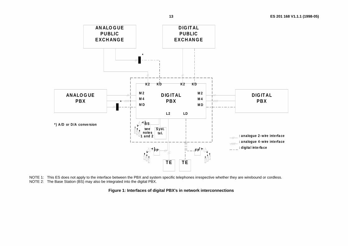
The PBX input and output for a connection through a digital PBX are located at the interfaces identified in clause 1 andshown in figures 1, 2 and 3.
3.1.2.3 Half connections (analogue 2-wire or 4-wire, or digital)
- Input connection: an unidirectional path from an input of a digital PBX to an output test point.
- Output connection: an unidirectional path from an input test point to an output of a digital PBX.
- Half connection: a bi-directional path comprised of an input connection and an output connection, both having the same interface.
3.1.3 Relative levels
3.1.3.1 Test points
The input and output test points are defined as 0 dBr points for the equipment under test.
NOTE: See annex D for a discussion of relative levels.
3.1.3.2 Analogue interfaces
The nominal relative level at the PBX input point is designated Li.
The nominal relative level at the PBX output point is designated Lo.
ETSI
ES 201 168 V1.1.1 (1998-05)12
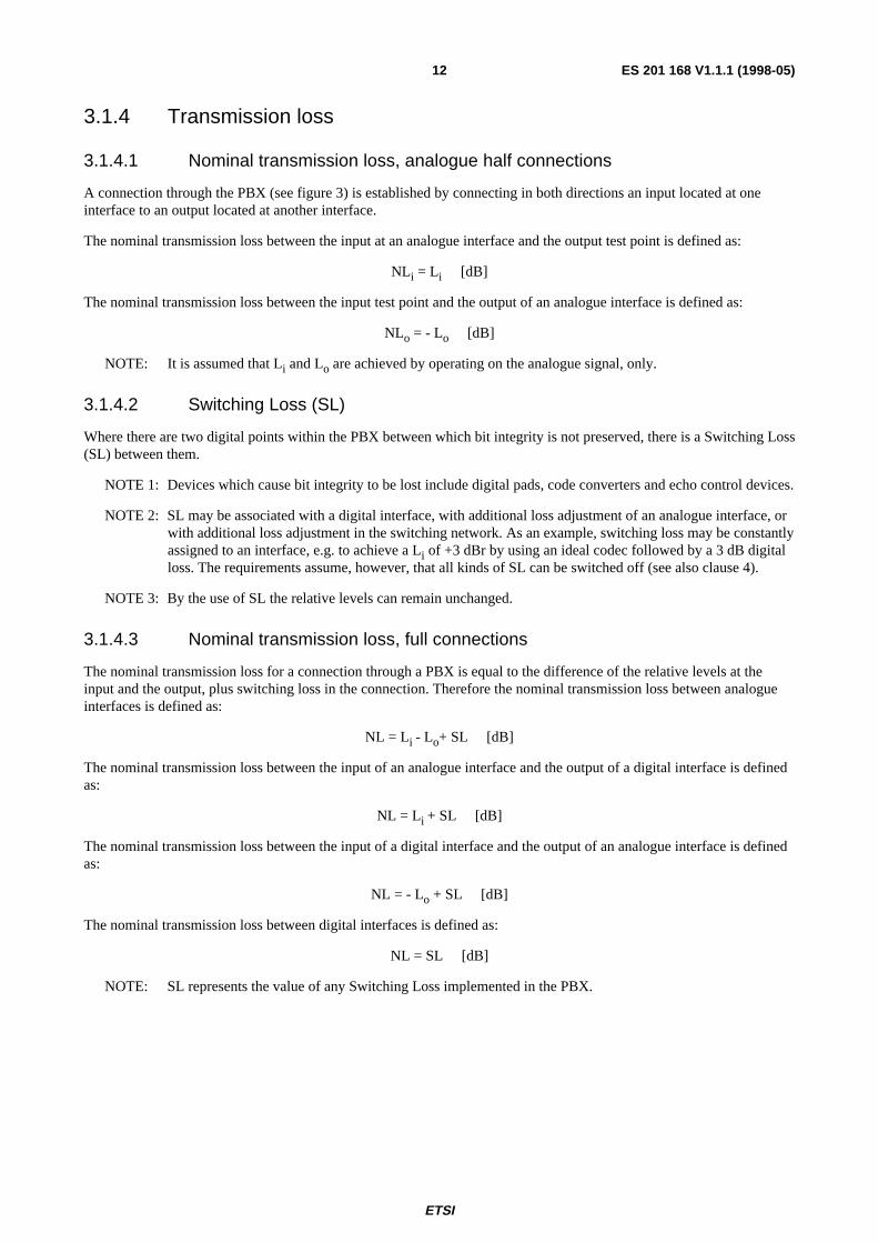
3.1.4 Transmission loss
3.1.4.1 Nominal transmission loss, analogue half connections
A connection through the PBX (see figure 3) is established by connecting in both directions an input located at oneinterface to an output located at another interface.
The nominal transmission loss between the input at an analogue interface and the output test point is defined as:
NLi = Li [dB]
The nominal transmission loss between the input test point and the output of an analogue interface is defined as:
NLo = - Lo [dB]
NOTE: It is assumed that Li and Lo are achieved by operating on the analogue signal, only.
3.1.4.2 Switching Loss (SL)
Where there are two digital points within the PBX between which bit integrity is not preserved, there is a Switching Loss(SL) between them.
NOTE 1: Devices which cause bit integrity to be lost include digital pads, code converters and echo control devices.
NOTE 2: SL may be associated with a digital interface, with additional loss adjustment of an analogue interface, orwith additional loss adjustment in the switching network. As an example, switching loss may be constantlyassigned to an interface, e.g. to achieve a Li of +3 dBr by using an ideal codec followed by a 3 dB digitalloss. The requirements assume, however, that all kinds of SL can be switched off (see also clause 4).
NOTE 3: By the use of SL the relative levels can remain unchanged.
3.1.4.3 Nominal transmission loss, full connections
The nominal transmission loss for a connection through a PBX is equal to the difference of the relative levels at theinput and the output, plus switching loss in the connection. Therefore the nominal transmission loss between analogueinterfaces is defined as:
NL = Li - Lo+ SL [dB]
The nominal transmission loss between the input of an analogue interface and the output of a digital interface is definedas:
NL = Li + SL [dB]
The nominal transmission loss between the input of a digital interface and the output of an analogue interface is definedas:
NL = - Lo + SL [dB]
The nominal transmission loss between digital interfaces is defined as:
NL = SL [dB]
NOTE: SL represents the value of any Switching Loss implemented in the PBX.
ES 201 168 V1.1.1 (1998-05)13
A N A L O G U E P U B L I C
E X C H A N G E
D I G I T A L P U B L I C
E X C H A N G E
A N A L O G U E P B X
D I G I T A L P B X
D I G I T A L P B X
K 2 K D K 2 K D
M 2
M 4
M D
M 2
M 4
M D
L 2 L D
*
*
* ) A / D o r D / A c o n v e r s i o n
: a n a l o g u e 2 - w i r e i n t e r f a c e
: a n a l o g u e 4 - w i r e i n t e r f a c e
: d i g i t a l i n t e r f a c e
T E T E
F P
B S
F P
S y s t . t e l .
s e e n o t e s
1 a n d 2
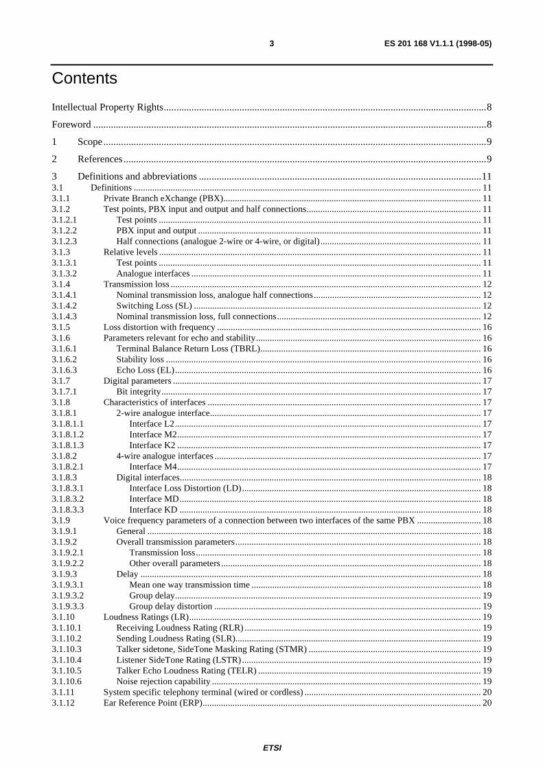
NOTE 1: This ES does not apply to the interface between the PBX and system specific telephones irrespective whether they are wirebound or cordless.NOTE 2: The Base Station (BS) may also be integrated into the digital PBX.
Figure 1: Interfaces of digital PBX's in network interconnections
ES 201 168 V1.1.1 (1998-05)14
TE TE
TE TE
DIGIT AL PB X
ANA LOG UEPBX
DIG ITA LPUB LIC
EX CH AN GE DIGITA LP UB LIC
EX CH AN GE
DIGIT ALPBX
K D
L2 LD
L2 L D
M 22
M 21
KD K 2
M 2 2M 2 1M 2 2M D
M 22M 22M 21M D
FP
B S
F P
Syst.te l.
: analogue 2-w ire in terfa ce: d ig ita l interface
seeno te s
1 and 2
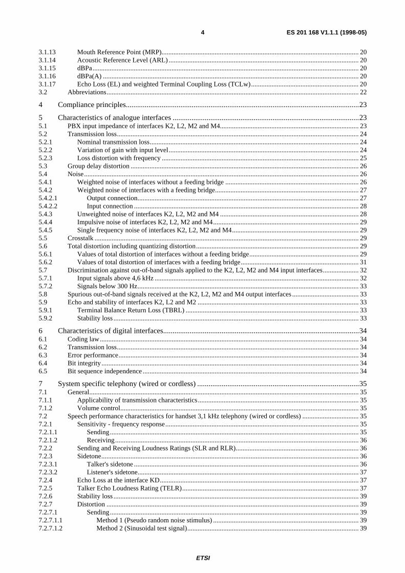
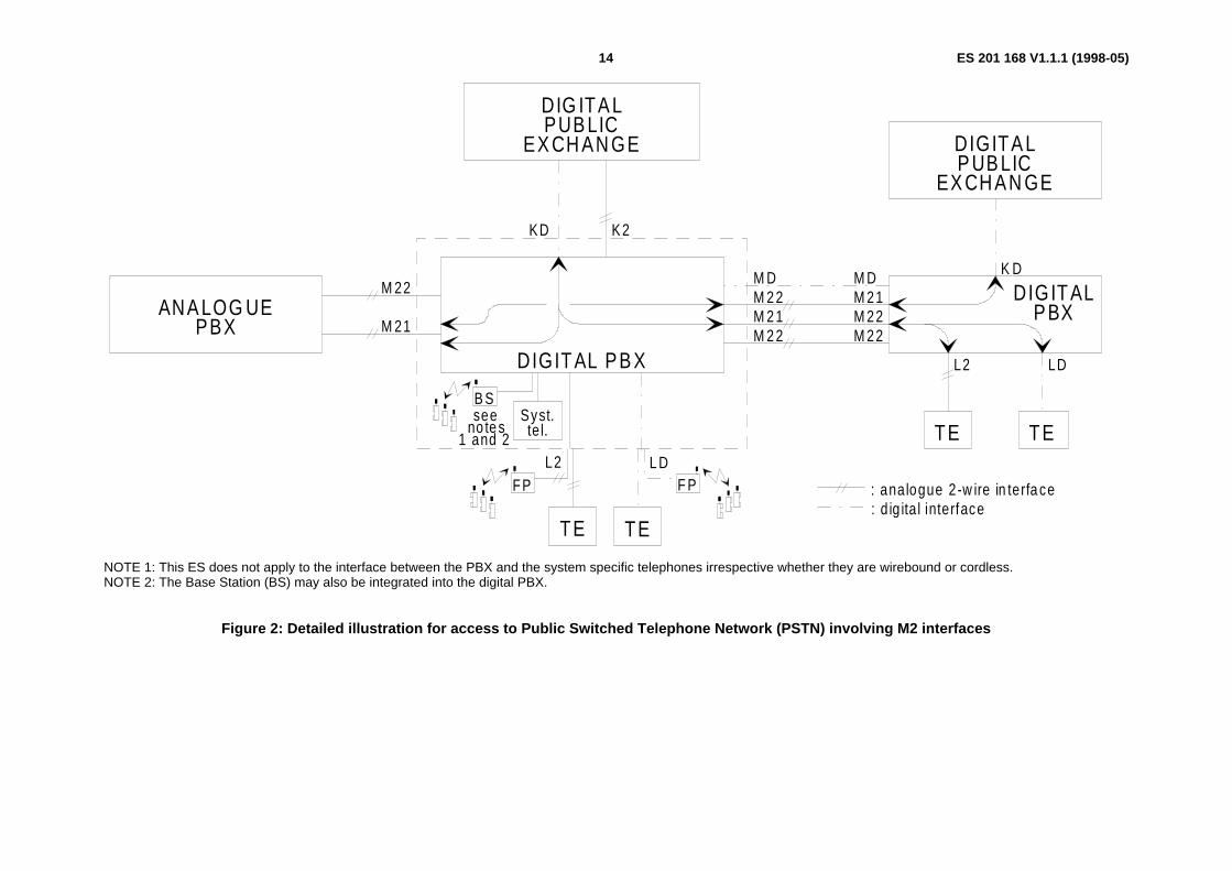
NOTE 1: This ES does not apply to the interface between the PBX and the system specific telephones irrespective whether they are wirebound or cordless.NOTE 2: The Base Station (BS) may also be integrated into the digital PBX.
Figure 2: Detailed illustration for access to Public Switched Telephone Network (PSTN) involving M2 interfaces

ES 201 168 V1.1.1 (1998-05)15
L i dB r
0 dB r
0 dB r
Lo dB r
0 dB r
0 dB r
Lo dB r
L i dB r
Lo dB r
L i dB r
P B XT erm ina tion
P B XT erm ina tion
D ig ita lS w itch ing S ys tem
E x tens ionT erm ina tion
L ineT erm ina tion
L ineT erm ination
T ransm iss ionequ ipm ent
(see n ote 4)
In te rfaceK D
In te rfaceM D
In te rface
K 2
In te rface
M 2
In te rfaceM 4
Tow ardsP riva teD om ain
Tow ardsPublic
D om ain
T i T o
0 dB r T es t P o in ts
In te rfaceLD
L i dB r
Lo dB r
In te rface
L2
0 dB r
0 dB r
E xtens ion L ine
D is tribu tion Fram e (D .F ) D .FD ig ita l PBX
P C M
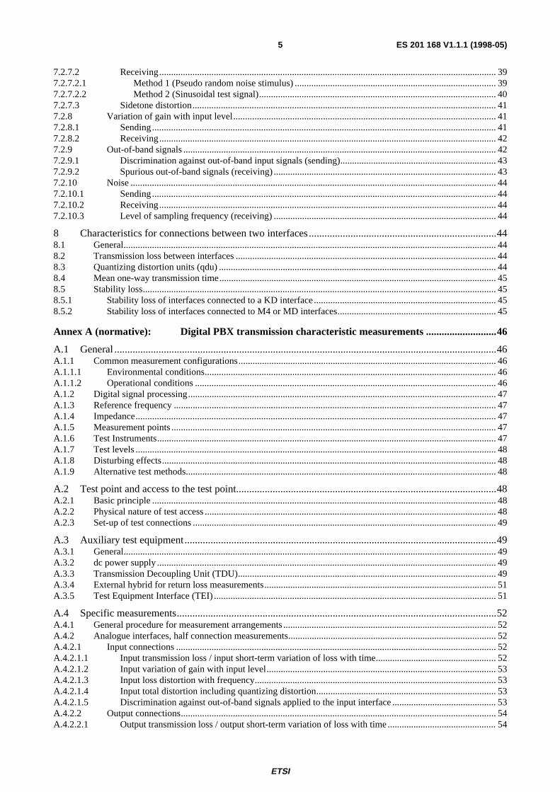
N ote 1 : D ig ita l loss pads , if requ ired , m ay be loc ated in the d ig ita lsw itch ing sys tem o r the P B X term ina ls (see subc lause 3 .1 .3 .2 ).
N o te 2 : T he v a lues o f L i and Lo fo r 2 -w ire and 4 -w ire in te rfacesa re , in gene ra l, no t equa l.
N o te 3 : In te rface ind ica tions a re on ly fo r w o rk ing pu rposes .
N o te 4 : T h is te rm re fers to d iffe rent types o f transm iss ion equ ipm en t(e .g . F D M , T D M etc .)
D ig ita l pa th
A na logue P a th
A na logue P ad
A /D o r D /A c onv e rte r
P C M : P u lse C ode M odu la tion
L ineT erm ina tion P C M
S ystemte lephone
T erm ina tion
S ys t.te l.
S ys temspecif icco rd less
te lephonete rm ination
B aseS tn .
Figure 3: Interfaces, transmission levels and test points at a digital PBX
ES 201 168 V1.1.1 (1998-05)16
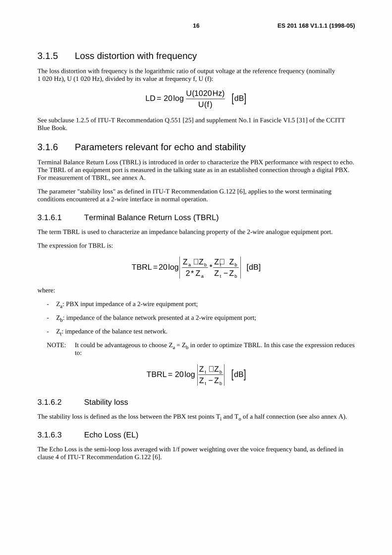
3.1.5 Loss distortion with frequency
The loss distortion with frequency is the logarithmic ratio of output voltage at the reference frequency (nominally1 020 Hz), U (1 020 Hz), divided by its value at frequency f, U (f):
[ ]LDU Hz
U fdB= 20
1020log
( )( )
See subclause 1.2.5 of ITU-T Recommendation Q.551 [25] and supplement No.1 in Fascicle VI.5 [31] of the CCITTBlue Book.
3.1.6 Parameters relevant for echo and stability
Terminal Balance Return Loss (TBRL) is introduced in order to characterize the PBX performance with respect to echo.The TBRL of an equipment port is measured in the talking state as in an established connection through a digital PBX.For measurement of TBRL, see annex A.
The parameter "stability loss" as defined in ITU-T Recommendation G.122 [6], applies to the worst terminatingconditions encountered at a 2-wire interface in normal operation.
3.1.6.1 Terminal Balance Return Loss (TBRL)
The term TBRL is used to characterize an impedance balancing property of the 2-wire analogue equipment port.
The expression for TBRL is:
TBRLZ Z
ZZ ZZ Z
dB]a b
a
t b
t b
=+ +
−20
2log
** [
where:
- Za: PBX input impedance of a 2-wire equipment port;
- Zb: impedance of the balance network presented at a 2-wire equipment port;
- Zt: impedance of the balance test network.
NOTE: It could be advantageous to choose Za = Zb in order to optimize TBRL. In this case the expression reducesto:
[ ]TBRLZ ZZ Z
dBt b
t b
=+−
20log
3.1.6.2 Stability loss
The stability loss is defined as the loss between the PBX test points Ti and To of a half connection (see also annex A).
3.1.6.3 Echo Loss (EL)
The Echo Loss is the semi-loop loss averaged with 1/f power weighting over the voice frequency band, as defined inclause 4 of ITU-T Recommendation G.122 [6].
ES 201 168 V1.1.1 (1998-05)17
3.1.7 Digital parameters
3.1.7.1 Bit integrity
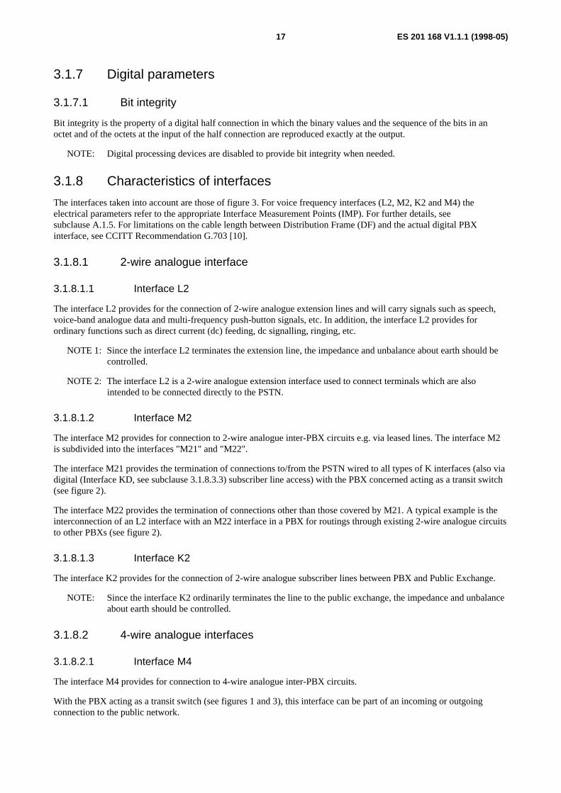
Bit integrity is the property of a digital half connection in which the binary values and the sequence of the bits in anoctet and of the octets at the input of the half connection are reproduced exactly at the output.
NOTE: Digital processing devices are disabled to provide bit integrity when needed.
3.1.8 Characteristics of interfaces
The interfaces taken into account are those of figure 3. For voice frequency interfaces (L2, M2, K2 and M4) theelectrical parameters refer to the appropriate Interface Measurement Points (IMP). For further details, seesubclause A.1.5. For limitations on the cable length between Distribution Frame (DF) and the actual digital PBXinterface, see CCITT Recommendation G.703 [10].
3.1.8.1 2-wire analogue interface
3.1.8.1.1 Interface L2
The interface L2 provides for the connection of 2-wire analogue extension lines and will carry signals such as speech,voice-band analogue data and multi-frequency push-button signals, etc. In addition, the interface L2 provides forordinary functions such as direct current (dc) feeding, dc signalling, ringing, etc.
NOTE 1: Since the interface L2 terminates the extension line, the impedance and unbalance about earth should becontrolled.
NOTE 2: The interface L2 is a 2-wire analogue extension interface used to connect terminals which are alsointended to be connected directly to the PSTN.
3.1.8.1.2 Interface M2
The interface M2 provides for connection to 2-wire analogue inter-PBX circuits e.g. via leased lines. The interface M2is subdivided into the interfaces "M21" and "M22".
The interface M21 provides the termination of connections to/from the PSTN wired to all types of K interfaces (also viadigital (Interface KD, see subclause 3.1.8.3.3) subscriber line access) with the PBX concerned acting as a transit switch(see figure 2).
The interface M22 provides the termination of connections other than those covered by M21. A typical example is theinterconnection of an L2 interface with an M22 interface in a PBX for routings through existing 2-wire analogue circuitsto other PBXs (see figure 2).
3.1.8.1.3 Interface K2
The interface K2 provides for the connection of 2-wire analogue subscriber lines between PBX and Public Exchange.
NOTE: Since the interface K2 ordinarily terminates the line to the public exchange, the impedance and unbalanceabout earth should be controlled.
3.1.8.2 4-wire analogue interfaces
3.1.8.2.1 Interface M4
The interface M4 provides for connection to 4-wire analogue inter-PBX circuits.
With the PBX acting as a transit switch (see figures 1 and 3), this interface can be part of an incoming or outgoingconnection to the public network.

ES 201 168 V1.1.1 (1998-05)18
NOTE: The performance of different transmission media used in conjunction with 4-wire analogue circuitsbetween PBXs is not addressed in t.
3.1.8.3 Digital interfaces
3.1.8.3.1 Interface Loss Distortion (LD)
The interface LD is a digital extension interface used to connect terminals which are also intended to be connecteddirectly to digital interfaces of the public switched network.
3.1.8.3.2 Interface MD
The interface MD provides for connection to a digital inter-PBX circuit.
3.1.8.3.3 Interface KD
The interface KD provides for the connection of a digital access to the public switched network.
3.1.9 Voice frequency parameters of a connection between two interfacesof the same PBX
3.1.9.1 General
This subclause provides guidance on obtaining the overall characteristics for connections between two interfaces of thesame PBX.
NOTE: For an overall connection involving one or more digital interfaces, the results quoted assume that an idealsend and receive side (see CCITT Recommendation G.712 [12]) is connected to the digital inputs andoutputs, respectively.
The transmission parameters relating to the input connection from a PBX interface to a PBX output test point will bereferred to as input parameters. Transmission parameters relating to the output connection from a PBX input test pointto a PBX interface will be referred to as output parameters. For additional information about the measurementconfigurations, see annex A.
3.1.9.2 Overall transmission parameters
3.1.9.2.1 Transmission loss
The transmission loss in each direction through the PBX is equal to the algebraic sum of the input transmission loss, theoutput transmission loss, and the Switching Loss (SL) in each direction between the two interfaces.
3.1.9.2.2 Other overall parameters
The overall characteristic for the following parameters can be obtained as given in subclause 3.1.9.2.1:
- loss distortion with frequency;
- variation of gain with input level.
3.1.9.3 Delay
3.1.9.3.1 Mean one way transmission time
The mean one way transmission time is the algebraic sum of the one-way transmission times in both directions oftransmission between the two interfaces (of the PBX) divided by two.
ES 201 168 V1.1.1 (1998-05)19
NOTE: The one-way transmission time through a PBX may vary mainly dependent on the PBX architecture, thetypes of connections involved and the traffic load.
3.1.9.3.2 Group delay
The time of propagation between two points of a certain element (for example the crest) of the envelope of a wave. For agiven frequency it is equal to the first derivative of the phase shift measured in radians, between these points, withreference to the angular frequency measured in radians per second.
3.1.9.3.3 Group delay distortion
The difference between group delay at a given frequency and minimum group delay, in the frequency band of interest.
3.1.10 Loudness Ratings (LR)
Within the context of ITU-T, a loudness rating is an objective measure of the loudness loss, i.e., a weighted,electro-acoustic loss between certain interfaces in the telephone network.
3.1.10.1 Receiving Loudness Rating (RLR)
The loudness loss between an electric interface and the Ear Reference Point (ERP).
3.1.10.2 Sending Loudness Rating (SLR)
The loudness loss between the Mouth Reference Point (MRP) and an electric interface.
3.1.10.3 Talker sidetone, SideTone Masking Rating (STMR)
The loudness loss between the MRP and the ERP via the sidetone path.
3.1.10.4 Listener SideTone Rating (LSTR)
The loudness loss between a diffuse pink sound field representing the room noise source and the ERP via the electricalsidetone path.
3.1.10.5 Talker Echo Loudness Rating (TELR)
The transmitted speech signal of the talking subscriber is delayed along the different sections of the transmission path,coupled at the far end and received again with further delay, affecting the talker with an echo of his own voice. Sincethis type of echo in the given configuration is only observed by the talker, it is called Talker Echo. The magnitude of thetalker echo is characterized by the Talker Echo Loudness Rating (TELR).
TELR = EL + SLR + RLR
Here SLR and RLR are the send and receive loudness ratings of the talker’s telephone set, referred to that 4-wireinterface where the Echo Loss (EL) (see subclause 3.1.17) applies.
3.1.10.6 Noise rejection capability
When room noise is present a higher received signal level (lower RLRH) is required to give the best possible receivingspeech quality and intelligibility. The increase in the receiving level is a function of increasing room noise level.
When room noise is present people rise their voice level (talk louder) and the sending speech level will be higher thanthe optimum level. By decreasing the sending sensitivity (higher SLRH) the sending level to the line will be aroundoptimum and at the same time the absolute level of the transmitted noise will decrease.
The increase in receiving sensitivity and the decrease in sending sensitivity is approximately linearly related toincreasing room noise level. For every dB increase in room noise level there is a corresponding increase in receiversensitivity and decrease in sending sensitivity of about 0,5 dB.
ES 201 168 V1.1.1 (1998-05)20
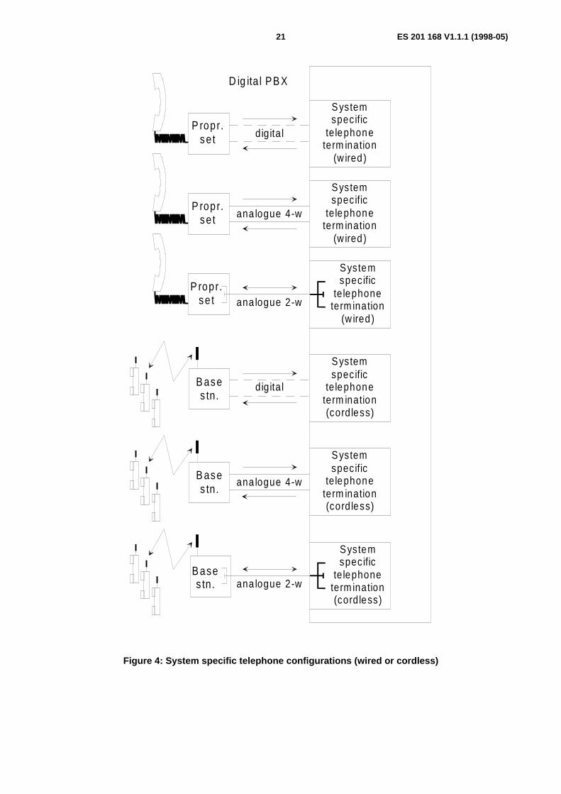
3.1.11 System specific telephony terminal (wired or cordless)
A system specific telephony terminal (wired or of a cordless system) is a telephony terminal used for a specific PBXfamily for use in a digital environment. The system specific telephony terminal (wired) or the Base Station (BS) of thecordless system may be connected via a digital or an analogue line to the system specific telephone termination (seefigure 4). The BS may also be integrated within the PBX. The system specific telephony terminal (including the airinterface of a cordless telephony terminal) is considered an integral part of the PBX in the sense that the characteristicsof the path between the PBX itself and the telephony terminal is not subject to standardization. The system specifictelephony terminal (wired or cordless) is not intended for direct connection to a public network.
3.1.12 Ear Reference Point (ERP)
A point located at the entrance to the ear canal of the listener's ear as described in figure A-1 ofITU-T Recommendation P.64 [21].
3.1.13 Mouth Reference Point (MRP)
A point 25 mm in front of and on the axis of the lip position of a typical human mouth (or artificial mouth) (seefigure A-1 of ITU-T Recommendation P.64 [21]).
3.1.14 Acoustic Reference Level (ARL)
The acoustic level which gives -10 dBm0 at the digital output test point.
3.1.15 dBPa
Sound pressure level relative to 1 Pa (no weighting).
3.1.16 dBPa(A)
Sound level relative to 1 Pa measured using the A-weighting defined in IEC 60651 [28].
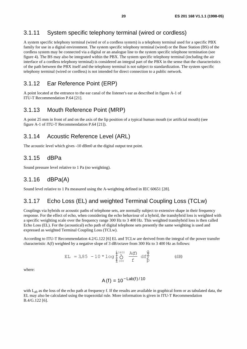
3.1.17 Echo Loss (EL) and weighted Terminal Coupling Loss (TCLw)
Couplings via hybrids or acoustic paths of telephone sets, are normally subject to extensive shape in their frequencyresponse. For the effect of echo, when considering the echo behaviour of a hybrid, the transhybrid loss is weighted witha specific weighting scale over the frequency range 300 Hz to 3 400 Hz. This weighted transhybrid loss is then calledEcho Loss (EL). For the (acoustical) echo path of digital telephone sets presently the same weighting is used andexpressed as weighted Terminal Coupling Loss (TCLw).
According to ITU-T Recommendation 4.2/G.122 [6] EL and TCLw are derived from the integral of the power transfercharacteristic A(f) weighted by a negative slope of 3 dB/octave from 300 Hz to 3 400 Hz as follows:
ELA f
fdf dB= -
ìíï
îï
üýïþò3 85 10
300
3400
, * log( )
( )
where:
A f Lab f( ) ( ) /= −10 10
with Lab as the loss of the echo path at frequency f. If the results are available in graphical form or as tabulated data, theEL may also be calculated using the trapezoidal rule. More information is given in ITU-T RecommendationB.4/G.122 [6].
ES 201 168 V1.1.1 (1998-05)21
B ases tn.
P ropr.se t
P ropr.se t
P ropr.se t
B ases tn.
B ases tn.
Systemspecific
te lephoneterm ination
(w ired )
Systemspecific
te lephoneterm ination
(w ired )
Systemspecific
te lephoneterm ination
(w ired )
Systemspecific
te lephoneterm ination(cordless)
Systemspecific
te lephoneterm ination(cordless)
Systemspecific
te lephoneterm ination(cordless)
D ig ita l PB X
ana logue 4-w
ana logue 2-w
digita l
ana logue 2-w
ana logue 4-w
digita l
Figure 4: System specific telephone configurations (wired or cordless)
ES 201 168 V1.1.1 (1998-05)22
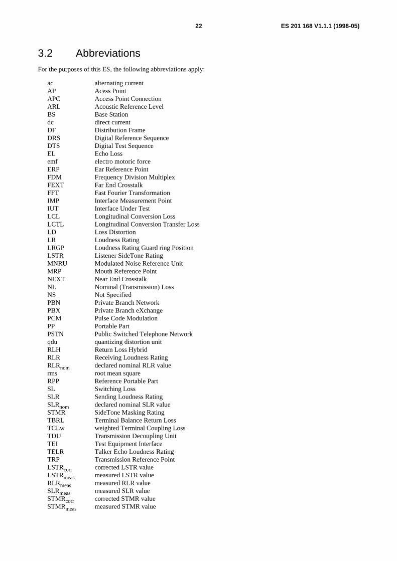
3.2 AbbreviationsFor the purposes of this ES, the following abbreviations apply:
ac alternating currentAP Acess PointAPC Access Point ConnectionARL Acoustic Reference LevelBS Base Stationdc direct currentDF Distribution FrameDRS Digital Reference SequenceDTS Digital Test SequenceEL Echo Lossemf electro motoric forceERP Ear Reference PointFDM Frequency Division MultiplexFEXT Far End CrosstalkFFT Fast Fourier TransformationIMP Interface Measurement PointIUT Interface Under TestLCL Longitudinal Conversion LossLCTL Longitudinal Conversion Transfer LossLD Loss DistortionLR Loudness RatingLRGP Loudness Rating Guard ring PositionLSTR Listener SideTone RatingMNRU Modulated Noise Reference UnitMRP Mouth Reference PointNEXT Near End CrosstalkNL Nominal (Transmission) LossNS Not SpecifiedPBN Private Branch NetworkPBX Private Branch eXchangePCM Pulse Code ModulationPP Portable PartPSTN Public Switched Telephone Networkqdu quantizing distortion unitRLH Return Loss HybridRLR Receiving Loudness RatingRLRnom declared nominal RLR valuerms root mean squareRPP Reference Portable PartSL Switching LossSLR Sending Loudness RatingSLRnom declared nominal SLR valueSTMR SideTone Masking RatingTBRL Terminal Balance Return LossTCLw weighted Terminal Coupling LossTDU Transmission Decoupling UnitTEI Test Equipment InterfaceTELR Talker Echo Loudness RatingTRP Transmission Reference PointLSTRcorr corrected LSTR valueLSTRmeas measured LSTR valueRLRmeas measured RLR valueSLRmeas measured SLR valueSTMRcorr corrected STMR valueSTMRmeas measured STMR value
ES 201 168 V1.1.1 (1998-05)23
4 Compliance principlesAll digital signal processing devices, which affect bit integrity of the 64 kbit/s speech-path within a digital PBX, e.g.digital loss or gain, digital echo control devices etc., shall be rendered inoperative, when measuring the transmissionparameters of the present document. However, if the NL is implemented by a digital loss or gain, the parameters"Nominal value" and "Tolerance" of the relative levels for input and output connections shall be measured with digitalloss or gain switched operative.
NOTE: In some digital PBXs such a digital loss or gain might be realized in a way, that it is not possible to switchthis digital signal processing inoperative during measurement. However, several transmission parameterslike quantizing distortion, variation of gain with input level etc., will be influenced additionally by digitalsignal processing. This means, the existing limits in this ES - derived only for the process ofencoding/decoding - may not be met.
5 Characteristics of analogue interfacesFor measuring 2-wire analogue interface conditions, refer also to annex A.
NOTE: Annex E provides, for transmission planning purposes, values used up to now with respect to impedancesand levels.
5.1 PBX input impedance of interfaces K2, L2, M2 and M4The nominal value of the PBX impedance for 2-wire interfaces shall be:
Za = 270 Ω + (750 Ω || 150 nF)
NOTE: The choice of this nominal value of the complex PBX impedance is providing a termination of:
- unloaded analogue subscriber line of a public exchange with reference to the interface K2;
- unloaded analogue lines between PBXs with reference to the interfaces M21 and M22 to ensure that the publicnetwork and every PBX will have adequate values of stability margin and echo.
The choice of this nominal value for the complex PBX impedance also ensures an adequate sidetone performance fortelephony terminals connected via analogue lines to the L2 interface, particularly those operated on short lines. Thisimpedance will also be suitable for extension lines fitted with voice band modems.
The nominal value of the PBX impedance for M4 interfaces shall be:
Za = 600 Ω
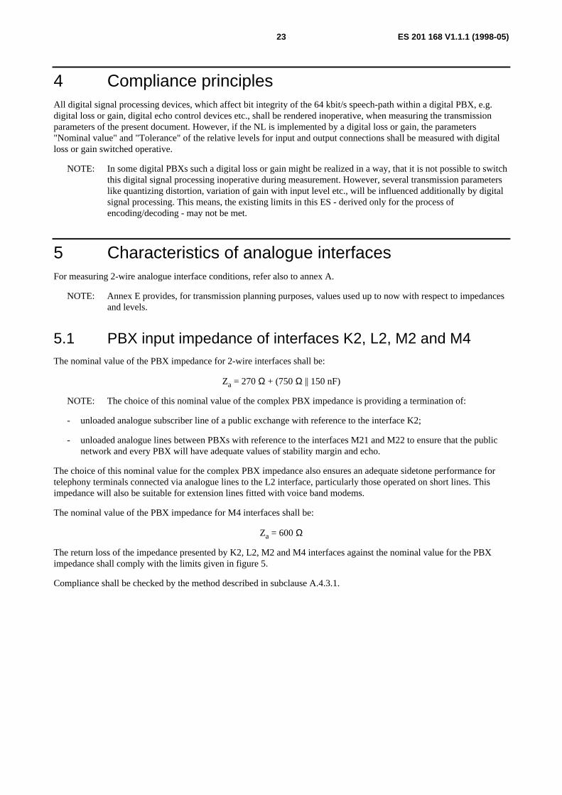
The return loss of the impedance presented by K2, L2, M2 and M4 interfaces against the nominal value for the PBXimpedance shall comply with the limits given in figure 5.
Compliance shall be checked by the method described in subclause A.4.3.1.
ES 201 168 V1.1.1 (1998-05)24
0,3 2 ,0 3 ,4
F req uen c y (f ) [log arithm ic s ca le ]
Ret
urn
loss
kH z
18
14
dB
0,50
Figure 5: Minimum value of return loss against the nominal PBX impedance
5.2 Transmission loss
5.2.1 Nominal transmission loss
The nominal input and output relative levels shall have a value stated by the supplier.
The difference between the measured value of the transmission loss, between the interface and the test point, and thenominal value of transmission loss (NLi and NLo) calculated from the stated value of relative level, shall lie within thefollowing ranges:
- input loss: -0,35 dB to +0,35 dB;
- output loss: -0,35 dB to +0,35 dB.
NOTE: These differences may arise, for example, from design tolerances and adjustment increments.
Compliance shall be checked by the methods described in subclauses A.4.2.1.1 and/or A.4.2.2.1.
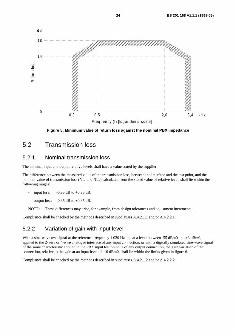
5.2.2 Variation of gain with input level
With a sine-wave test signal at the reference frequency 1 020 Hz and at a level between -55 dBm0 and +3 dBm0,applied to the 2-wire or 4-wire analogue interface of any input connection, or with a digitally simulated sine-wave signalof the same characteristic applied to the PBX input test point Ti of any output connection, the gain variation of thatconnection, relative to the gain at an input level of -10 dBm0, shall lie within the limits given in figure 6.
Compliance shall be checked by the methods described in subclauses A.4.2.1.2 and/or A.4.2.2.2.

ES 201 168 V1.1.1 (1998-05)25
+ 3 - 1 0 - 4 0 - 5 5
I n p u t l e v e l d B m 0
- 1 , 6
- 0 , 6
+ 0 , 6
+ 1 , 6
d B
- 5 0 - 0 , 3
+ 0 , 3
Var
iatio
n of
gai
n
Figure 6: Variation of gain with input level
5.2.3 Loss distortion with frequency
The loss distortion with frequency of any input or output connection according to subclause 3.1.5 shall lie within thelimits shown in the mask of figures 7 and 8, respectively. The preferred input level is -10 dBm0.
Compliance shall be checked by the methods described in subclauses A.4.2.1.3 and/or A.4.2.2.3.
0 ,4 1 ,020 2 ,0 2 ,4 3,0 3,4 3 ,6 kH z
0 ,350 ,45
0
-0 ,30
0 ,700 ,75
1,0
1,7
dB
0,6
F requency (f)
Loss
0 ,20 ,3
0
Figure 7: Loss distortion with frequency - input connection

ES 201 168 V1.1.1 (1998-05)26
0 ,4 1 ,020 2 ,0 2 ,4 3,0 3,4 3 ,6 kH z
0 ,350 ,45
0
-0 ,30
0 ,700 ,75
1,0
1,7
dB
0,60 ,3
F requency (f)
Loss
0
Figure 8: Loss distortion with frequency - output connection
5.3 Group delay distortionThere are no requirements for group delay distortion.
5.4 NoiseNOTE: When evaluating the PBX noise characteristics, two components of noise should be considered. One of
these arises from the Pulse Code Modulation (PCM) coding/decoding process, the other from analoguesources, e.g. signalling circuits, power supply, line power feeding on both sides of a connection betweentwo interfaces through the same PBX.
The noise arising from the PCM encoding process is limited by CCITT Recommendation G.712 [12] forall analogue interface types. The noise arising from analogue sources is considered in CCITTRecommendation G.103 [4] and ITU-T Recommendation Q.552 [26]. Its value can be different fordifferent interface types. For a given PBX (single or included in a private network) it is important,according to clause 11 of CCITT Recommendation G.171 [8], that the constituent parts be designed inaccordance with the relevant CCITT Recommendation covering the noise for public exchanges. Normally,this practice can guarantee an appropriate behaviour of the equipment. The above rules apply to bothweighted noise and total distortion.
5.4.1 Weighted noise of interfaces without a feeding bridge
NOTE: For the calculation of these values, two components of noise should be considered: noise arising from thecoding process and noise from the PBX power supply and other analogue sources transmitted throughsignalling circuits. The first component is limited by clause 9 of CCITT Recommendation G.712 [12] to-67 dBm0p for an input connection and to -70 dBm0p for an output connection. The other component islimited by clause 3 of CCITT Recommendation G.123 [7] to -70 dBm0p for each interface.
The maximum values for overall weighted noise at the outputs of a half connection shall be:
ES 201 168 V1.1.1 (1998-05)27
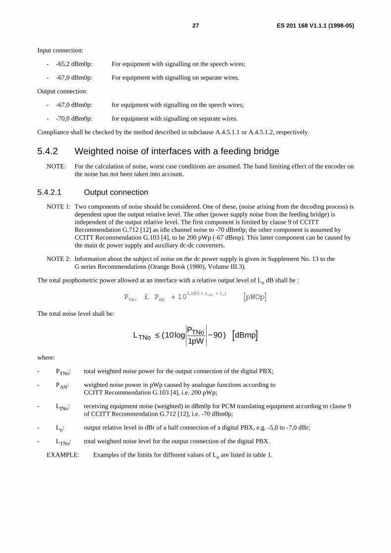
Input connection:
- -65,2 dBm0p: For equipment with signalling on the speech wires;
- -67,0 dBm0p: For equipment with signalling on separate wires.
Output connection:
- -67,0 dBm0p: for equipment with signalling on the speech wires;
- -70,0 dBm0p: for equipment with signalling on separate wires.
Compliance shall be checked by the method described in subclause A.4.5.1.1 or A.4.5.1.2, respectively.
5.4.2 Weighted noise of interfaces with a feeding bridge
NOTE: For the calculation of noise, worst case conditions are assumed. The band limiting effect of the encoder onthe noise has not been taken into account.
5.4.2.1 Output connection
NOTE 1: Two components of noise should be considered. One of these, (noise arising from the decoding process) isdependent upon the output relative level. The other (power supply noise from the feeding bridge) isindependent of the output relative level. The first component is limited by clause 9 of CCITTRecommendation G.712 [12] as idle channel noise to -70 dBm0p; the other component is assumed byCCITT Recommendation G.103 [4], to be 200 pWp (-67 dBmp). This latter component can be caused bythe main dc power supply and auxiliary dc-dc converters.
NOTE 2: Information about the subject of noise on the dc power supply is given in Supplement No. 13 to theG series Recommendations (Orange Book (1980), Volume III.3).
The total psophometric power allowed at an interface with a relative output level of Lo dB shall be :
[ ]P P pWOpTNo AN
L LINo o£ ++ +
100 1 90,( )
The total noise level shall be:
[ ]LP
pWdBmpTNo
TNo≤ −( log )101
90
where:
- PTNo: total weighted noise power for the output connection of the digital PBX;
- PAN: weighted noise power in pWp caused by analogue functions according toCCITT Recommendation G.103 [4], i.e. 200 pWp;
- LINo: receiving equipment noise (weighted) in dBm0p for PCM translating equipment according to clause 9of CCITT Recommendation G.712 [12], i.e. -70 dBm0p;
- Lo: output relative level in dBr of a half connection of a digital PBX, e.g. -5,0 to -7,0 dBr;
- LTNo: total weighted noise level for the output connection of the digital PBX.
EXAMPLE: Examples of the limits for different values of Lo are listed in table 1.

ES 201 168 V1.1.1 (1998-05)28
Table 1: Examples of the limits for different values of L o
Lo [dBr] P TNo [pWp] L TNo [dBmp]
-5,0 231,6 -66,4-6,0 225,1 -66,5-7,0 220,0 -66,6
Compliance shall be checked by the method described in subclause A.4.5.1.2.
5.4.2.2 Input connection
NOTE: Two components of noise should be considered. One of these (noise arising from the encoding process) isdependent upon the input relative level. The other (power supply noise from the feeding bridge) shall becorrected by the input relative level for calculation at the PBX output test point To. The first component islimited by clause 9 of CCITT Recommendation G.712 [12] as idle channel noise to -67 dBm0p; the othercomponent is assumed by CCITT Recommendation G.103 [4] to be 200 pWp (-67 dBmp) which results in-67 dBmp-Li at the PBX output test point To.
The total psophometric power allowed at the PBX output test point To with a relative input level of Li shall be:
[ ]P P pWopTNi ANL Li INi£ * +-0 +10 101 0 1 90, , ( )
and the total noise level shall be:
[ ]LPpW
dBm pTNiTNi≤ −( log )10
190 0
where:
- PTNi: total weighted noise power for the input connection of the digital PBX;
- PAN: weighted noise power in pWp caused by analogue functions according toCCITT Recommendation G.103 [4], i.e. 200 pWp;
- LINi: idle channel noise (weighted) in dBm0p for the input connection of a digital PBX according toclause 9 of CCITT Recommendation G.712 [12], i.e. -67 dBm0p;
- Li: input relative level in dBr of a half connection of a digital PBX, e.g. 0 to +2.0 dBr;
- LTNi: total weighted noise level for the input connection of the digital PBX.
EXAMPLE: Examples of the limits for different values of Lo are listed in table 2.
Table 2: Examples of the limits for different values of L i
Li [dBr] P TNi [pWp] L TNi [dBm0p]
0 399,5 -64,0
+1,0 358,4 -64,5
+2,0 325,7 -64,9
Compliance shall be checked by the method described in subclause A.4.5.1.1.
5.4.3 Unweighted noise of interfaces K2, L2, M2 and M4
There are no requirements for unweighted noise.
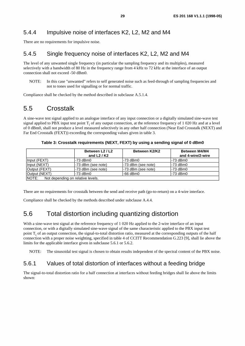
ES 201 168 V1.1.1 (1998-05)29
5.4.4 Impulsive noise of interfaces K2, L2, M2 and M4
There are no requirements for impulsive noise.
5.4.5 Single frequency noise of interfaces K2, L2, M2 and M4
The level of any unwanted single frequency (in particular the sampling frequency and its multiples), measuredselectively with a bandwidth of 80 Hz in the frequency range from 4 kHz to 72 kHz at the interface of an outputconnection shall not exceed -50 dBm0.
NOTE: In this case "unwanted" refers to self generated noise such as feed-through of sampling frequencies andnot to tones used for signalling or for normal traffic.
Compliance shall be checked by the method described in subclause A.5.1.4.
5.5 CrosstalkA sine-wave test signal applied to an analogue interface of any input connection or a digitally simulated sine-wave testsignal applied to PBX input test point Ti of any output connection, at the reference frequency of 1 020 Hz and at a levelof 0 dBm0, shall not produce a level measured selectively in any other half connection (Near End Crosstalk (NEXT) andFar End Crosstalk (FEXT)) exceeding the corresponding values given in table 3.
Table 3: Crosstalk requirements (NEXT, FEXT) by using a sending signal of 0 dBm0
Between L2 / L2and L2 / K2
Between K2/K2 Between M4/M4and 4-wire/2-wire
Input (FEXT) -73 dBm0 -73 dBm0 -73 dBm0Input (NEXT) -73 dBm (see note) -73 dBm (see note) -73 dBm0Output (FEXT) -73 dBm (see note) -73 dBm (see note) -73 dBm0Output (NEXT) -73 dBm0 -66 dBm0 -73 dBm0NOTE: Not depending on relative levels.
There are no requirements for crosstalk between the send and receive path (go-to-return) on a 4-wire interface.
Compliance shall be checked by the methods described under subclause A.4.4.
5.6 Total distortion including quantizing distortionWith a sine-wave test signal at the reference frequency of 1 020 Hz applied to the 2-wire interface of an inputconnection, or with a digitally simulated sine-wave signal of the same characteristic applied to the PBX input testpoint Ti of an output connection, the signal-to-total distortion ratio, measured at the corresponding outputs of the halfconnection with a proper noise weighting, specified in table 4 of CCITT Recommendation G.223 [9], shall lie above thelimits for the applicable interface given in subclause 5.6.1 or 5.6.2.
NOTE: The sinusoidal test signal is chosen to obtain results independent of the spectral content of the PBX noise.
5.6.1 Values of total distortion of interfaces without a feeding bridge
The signal-to-total distortion ratio for a half connection at interfaces without feeding bridges shall lie above the limitsshown:
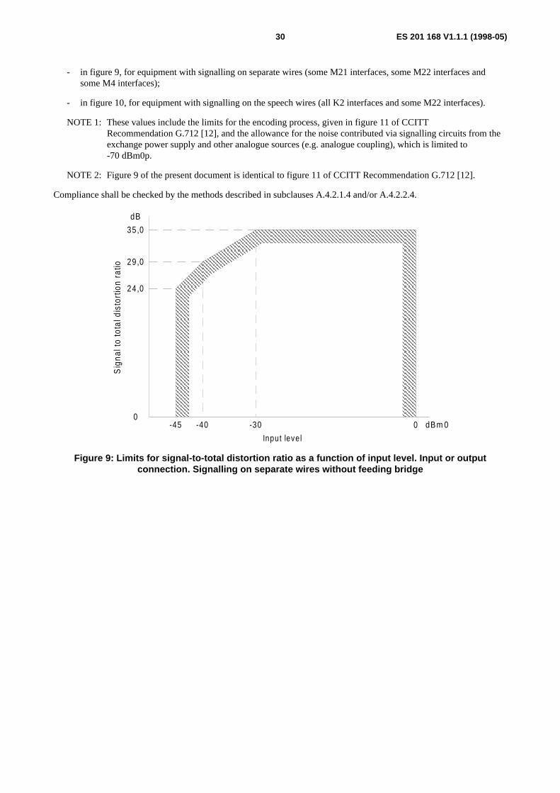
ES 201 168 V1.1.1 (1998-05)30
- in figure 9, for equipment with signalling on separate wires (some M21 interfaces, some M22 interfaces andsome M4 interfaces);
- in figure 10, for equipment with signalling on the speech wires (all K2 interfaces and some M22 interfaces).
NOTE 1: These values include the limits for the encoding process, given in figure 11 of CCITTRecommendation G.712 [12], and the allowance for the noise contributed via signalling circuits from theexchange power supply and other analogue sources (e.g. analogue coupling), which is limited to-70 dBm0p.
NOTE 2: Figure 9 of the present document is identical to figure 11 of CCITT Recommendation G.712 [12].
Compliance shall be checked by the methods described in subclauses A.4.2.1.4 and/or A.4.2.2.4.
35,0
dB
0-45 -40 -30 0 dBm 0
Input leve l
Sig
nal t
o to
tal d
isto
rtio
n ra
tio 29 ,0
24,0
Figure 9: Limits for signal-to-total distortion ratio as a function of input level. Input or outputconnection. Signalling on separate wires without feeding bridge
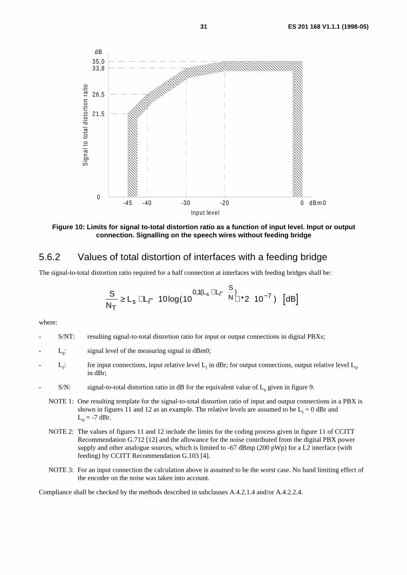
ES 201 168 V1.1.1 (1998-05)31
35,033,8
26,5
21,5
dB
0-45 -40 -30 -20 0 dBm 0
Input leve l
Sig
nal t
o to
tal d
isto
rtio
n ra
tio
Figure 10: Limits for signal to-total distortion ratio as a function of input level. Input or outputconnection. Signalling on the speech wires without feeding bridge
5.6.2 Values of total distortion of interfaces with a feeding bridge
The signal-to-total distortion ratio required for a half connection at interfaces with feeding bridges shall be:
[ ]SN
L L dBT
s rL L
SNs r
≥ + − + ∗+ − −10 10 2 10
0 1 7log( ), ( )
where:
- S/NT: resulting signal-to-total distortion ratio for input or output connections in digital PBXs;
- Ls: signal level of the measuring signal in dBm0;
- Lr: for input connections, input relative level Li in dBr; for output connections, output relative level Loin dBr;
- S/N: signal-to-total distortion ratio in dB for the equivalent value of Ls given in figure 9.
NOTE 1: One resulting template for the signal-to-total distortion ratio of input and output connections in a PBX isshown in figures 11 and 12 as an example. The relative levels are assumed to be Li = 0 dBr andLo = -7 dBr.
NOTE 2: The values of figures 11 and 12 include the limits for the coding process given in figure 11 of CCITTRecommendation G.712 [12] and the allowance for the noise contributed from the digital PBX powersupply and other analogue sources, which is limited to -67 dBmp (200 pWp) for a L2 interface (withfeeding) by CCITT Recommendation G.103 [4].
NOTE 3: For an input connection the calculation above is assumed to be the worst case. No band limiting effect ofthe encoder on the noise was taken into account.
Compliance shall be checked by the methods described in subclauses A.4.2.1.4 and/or A.4.2.2.4.

ES 201 168 V1.1.1 (1998-05)32
35,0
dB
0-45 -40 -30 0 dBm 0
Input leve l
Sig
nal t
o to
tal d
isto
rtio
n ra
tio
-20
32,9
24,9
19,9
Figure 11: Limits for signal-to-total distortion ratio as a function of input level including analoguenoise. Input connection (L i = 0 dBr). Interfaces L2 and M2 with feeding bridges
35,0dB
0-45 -40 -30 0 dBm 0
Input leve l
Sig
nal t
o to
tal d
isto
rtio
n ra
tio
-20 -10
33,8
28,8
19,5
14,5
Figure 12: Limits for signal-to-total distortion ratio as a function of input level including analoguenoise. Output connection (Lo = - 7 dBr). Interfaces L2 and M2 with feeding bridges
5.7 Discrimination against out-of-band signals applied to theK2, L2, M2 and M4 input interfaces
5.7.1 Input signals above 4,6 kHz
With a sine-wave signal in the range from 4,6 kHz to 72 kHz applied to the 2-wire and/or 4-wire interface of an inputconnection at a level of -25 dBm0, the level of any image frequency produced in the time slot corresponding to the inputconnection shall be at least 25 dB below the level of the test signal.
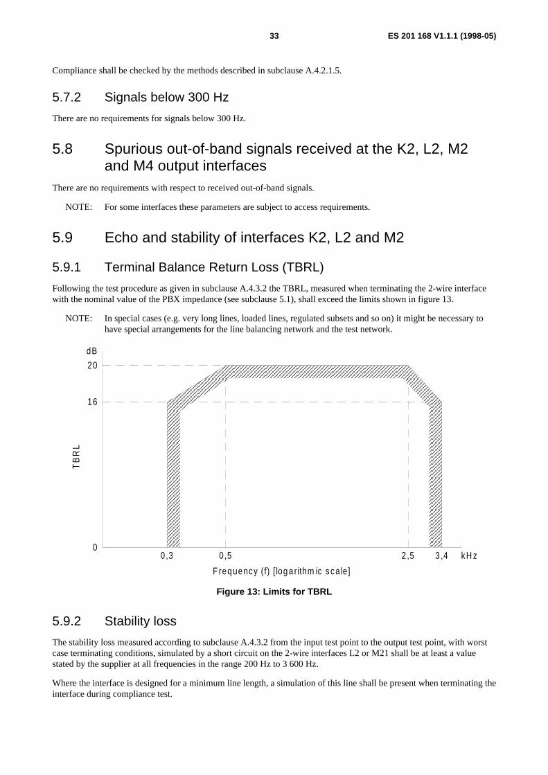
ES 201 168 V1.1.1 (1998-05)33
Compliance shall be checked by the methods described in subclause A.4.2.1.5.
5.7.2 Signals below 300 Hz
There are no requirements for signals below 300 Hz.
5.8 Spurious out-of-band signals received at the K2, L2, M2and M4 output interfaces
There are no requirements with respect to received out-of-band signals.
NOTE: For some interfaces these parameters are subject to access requirements.
5.9 Echo and stability of interfaces K2, L2 and M2
5.9.1 Terminal Balance Return Loss (TBRL)
Following the test procedure as given in subclause A.4.3.2 the TBRL, measured when terminating the 2-wire interfacewith the nominal value of the PBX impedance (see subclause 5.1), shall exceed the limits shown in figure 13.
NOTE: In special cases (e.g. very long lines, loaded lines, regulated subsets and so on) it might be necessary tohave special arrangements for the line balancing network and the test network.
0,3 3 ,4
F req uency (f) [ log a rithm ic sca le]
TB
RL
kH z
dB
0,5
20
16
2 ,50
Figure 13: Limits for TBRL
5.9.2 Stability loss
The stability loss measured according to subclause A.4.3.2 from the input test point to the output test point, with worstcase terminating conditions, simulated by a short circuit on the 2-wire interfaces L2 or M21 shall be at least a valuestated by the supplier at all frequencies in the range 200 Hz to 3 600 Hz.
Where the interface is designed for a minimum line length, a simulation of this line shall be present when terminating theinterface during compliance test.

ES 201 168 V1.1.1 (1998-05)34
NOTE 1: In some PBXs the 4-wire call path is left open during the dialling or before the terminating equipment hasanswered the call, thus preventing the effects due to short-circuit and open-circuit termination conditions.
NOTE 2: Where the digital PBX is connected to the public digital exchange using a 4-wire line, the half connectionof the digital PBX may provide the total stability loss of the entire path across the public network. Thevalue of stability loss that is required for a 2-wire interface is a matter of national control provided that therequirements of ITU-T Recommendation G.122 [6] are met. A stability loss of 6 dB at all frequenciesbetween 200 Hz and 3 600 Hz will ensure that the ITU-T Recommendation G.122 [6] requirements aremet. However, a stability loss between 6 dB and 0 dB will formally comply with the requirements ofITU-T Recommendation G.122 [6] but further study is required to provide guidance in this area.
NOTE 3: In the case that the input impedance is not equal to the balance impedance (see note in subclause 5.9.1),the stability loss under short-circuit terminating conditions may result in lower values than in the case ofequal impedances.
6 Characteristics of digital interfaces
6.1 Coding lawThe coding law of the digital interface shall be A-law according to CCITT Recommendation G.711 [11].
6.2 Transmission lossThe NL of a digital half-connection shall have a value stated by the supplier.
NOTE 1: If there is a loss or gain between the interface and the test point, this is considered as SL as defined insubclause 3.1.4.2.
The difference between the measured value of the transmission loss and the stated NL shall lie within the ranges-0,15 dB to +0,15 dB, for input and output loss.
NOTE 2: These differences may apply when bit integrity is not preserved between interface and test point and mayarise for example from design tolerances and adjustment increments, e.g. when the interface uses A-lawcoding and the test point uses µ-law coding.
6.3 Error performanceThere are no requirements.
6.4 Bit integrityThere are no requirements.
6.5 Bit sequence independenceThere are no requirements.
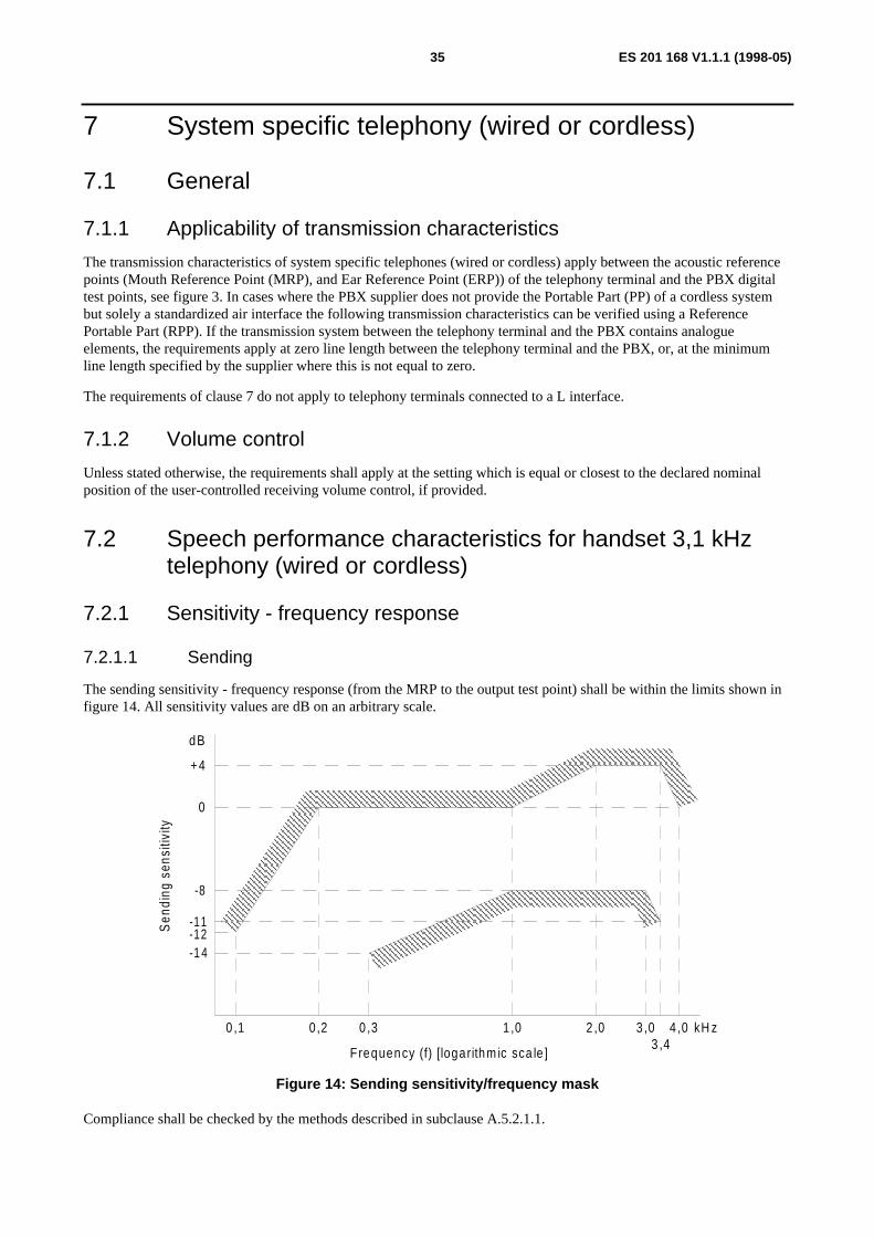
ES 201 168 V1.1.1 (1998-05)35
7 System specific telephony (wired or cordless)
7.1 General
7.1.1 Applicability of transmission characteristics
The transmission characteristics of system specific telephones (wired or cordless) apply between the acoustic referencepoints (Mouth Reference Point (MRP), and Ear Reference Point (ERP)) of the telephony terminal and the PBX digitaltest points, see figure 3. In cases where the PBX supplier does not provide the Portable Part (PP) of a cordless systembut solely a standardized air interface the following transmission characteristics can be verified using a ReferencePortable Part (RPP). If the transmission system between the telephony terminal and the PBX contains analogueelements, the requirements apply at zero line length between the telephony terminal and the PBX, or, at the minimumline length specified by the supplier where this is not equal to zero.
The requirements of clause 7 do not apply to telephony terminals connected to a L interface.
7.1.2 Volume control
Unless stated otherwise, the requirements shall apply at the setting which is equal or closest to the declared nominalposition of the user-controlled receiving volume control, if provided.
7.2 Speech performance characteristics for handset 3,1 kHztelephony (wired or cordless)
7.2.1 Sensitivity - frequency response
7.2.1.1 Sending
The sending sensitivity - frequency response (from the MRP to the output test point) shall be within the limits shown infigure 14. All sensitivity values are dB on an arbitrary scale.
0
0 ,1 0 ,2 0 ,3 1 ,0 2 ,0 3 ,0 4 ,0 kH z3 ,4
-1 4
-8
+ 4
dB
-11
Frequency (f) [logarithm ic sca le ]
Sen
ding
sen
sitiv
ity
-12
Figure 14: Sending sensitivity/frequency mask
Compliance shall be checked by the methods described in subclause A.5.2.1.1.
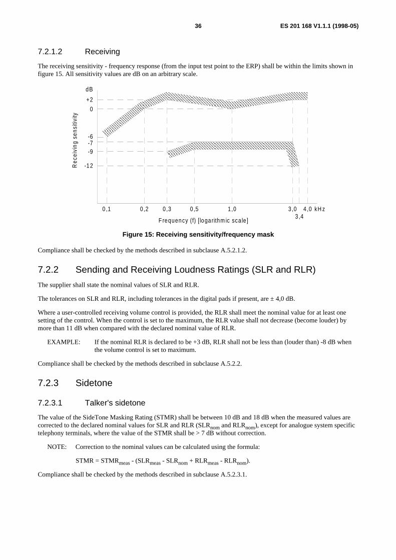
ES 201 168 V1.1.1 (1998-05)36
7.2.1.2 Receiving
The receiving sensitivity - frequency response (from the input test point to the ERP) shall be within the limits shown infigure 15. All sensitivity values are dB on an arbitrary scale.
0
0 ,1 0 ,2 0 ,3 1 ,0 3 ,0 4 ,0 kH z3 ,4
-12
dB
F requency (f) [loga rithm ic sca le ]
Rec
eivi
ng s
ensi
tivity
-7
+2
0 ,5
-9
-6
Figure 15: Receiving sensitivity/frequency mask
Compliance shall be checked by the methods described in subclause A.5.2.1.2.
7.2.2 Sending and Receiving Loudness Ratings (SLR and RLR)
The supplier shall state the nominal values of SLR and RLR.
The tolerances on SLR and RLR, including tolerances in the digital pads if present, are ± 4,0 dB.
Where a user-controlled receiving volume control is provided, the RLR shall meet the nominal value for at least onesetting of the control. When the control is set to the maximum, the RLR value shall not decrease (become louder) bymore than 11 dB when compared with the declared nominal value of RLR.
EXAMPLE: If the nominal RLR is declared to be +3 dB, RLR shall not be less than (louder than) -8 dB whenthe volume control is set to maximum.
Compliance shall be checked by the methods described in subclause A.5.2.2.
7.2.3 Sidetone
7.2.3.1 Talker's sidetone
The value of the SideTone Masking Rating (STMR) shall be between 10 dB and 18 dB when the measured values arecorrected to the declared nominal values for SLR and RLR (SLRnom and RLRnom), except for analogue system specifictelephony terminals, where the value of the STMR shall be > 7 dB without correction.
NOTE: Correction to the nominal values can be calculated using the formula:
STMR = STMRmeas - (SLRmeas - SLRnom + RLRmeas - RLRnom).
Compliance shall be checked by the methods described in subclause A.5.2.3.1.

ES 201 168 V1.1.1 (1998-05)37
7.2.3.2 Listener's sidetone
The value of the Listener Side Tone Rating (LSTR) shall be not less than 15 dB when the measured values are correctedin accordance to the declared nominal values for SLR and RLR (SLRnom and RLRnom), except for system specificcordless telephony terminals.
For system specific cordless telephony terminals the value of the LSTR shall be not less than 10 dB and in case wherenoise rejection capabilities are declared by the supplier the LSTR shall be not less than 15 dB when the measured valuesare corrected with respect to the declared nominal values for SLR and RLR (SLRnom and RLRnom).
NOTE: Correction the nominal values can be calculated using the formula:
LSTR = LSTRmeas - (SLRmeas - SLRnom + RLRmeas - RLRnom).
Alternatively if requested by the terminal supplier the value of the weighted average D (the difference of sendsensitivities between diffuse and direct sound field) shall not be less than +2 dB when measured with the ITU-TRecommendation P.57 Type 3.2 artificial ear. For system specific cordless telephony terminals the weighted average Dshall not be less than -5 dB and with noise rejection not be less than 0 dB.
For 2-wire analogue system specific telephony terminals there is no requirement for LSTR and/or the value of theweighted average D.
Compliance shall be checked by the methods described in subclause A.5.2.3.2.
7.2.4 Echo Loss at the interface KD
The EL of the system specific telephony terminal shall be measured at the interface KD with a power weighting over thevoice frequency band, in accordance with ITU-T Recommendation G.122 [6]. Echo can derive from one or more echopathes. Each echo path shall fulfil the requirements listed in table 4:
Table 4: Required Echo Loss at the interface KD
One-way delay of the echo-path required Echo Loss Remarks
< 5 ms > 22 dB
5-20 ms > 30 dB When there is(a) no echo-path with a one-way delay of less than 5 msand(b) the EL of the path with a one-way delay of 5 ..20 ms is in the range 30 .. 46 dB,then an Artificial EL of 24 ± 2 dB shall be inserted witha one way delay less than 5 ms from the interface KD.
> 20 ms > 46 dB
NOTE: The purpose of the Artificial EL is to ensure that an echo control device in an external network will workproperly.
The manufacturer shall declare the number of echo pathes, their associated one-way delay and the chosen solution.
Compliance shall be checked by the methods described in subclause A.5.2.4.
7.2.5 Talker Echo Loudness Rating (TELR)
The Talker Echo Loudness Rating (TELR) shall be measured at the acoustic interface of the system specific telephonyterminal with a power weighting over the voice frequency band, in accordance with ITU-T Recommendation G.122 [6]to test the hybrids and the performance of the network echo control inside the PBX.
The correct working of the soft suppressor of cordless system specific telephones will not be tested.
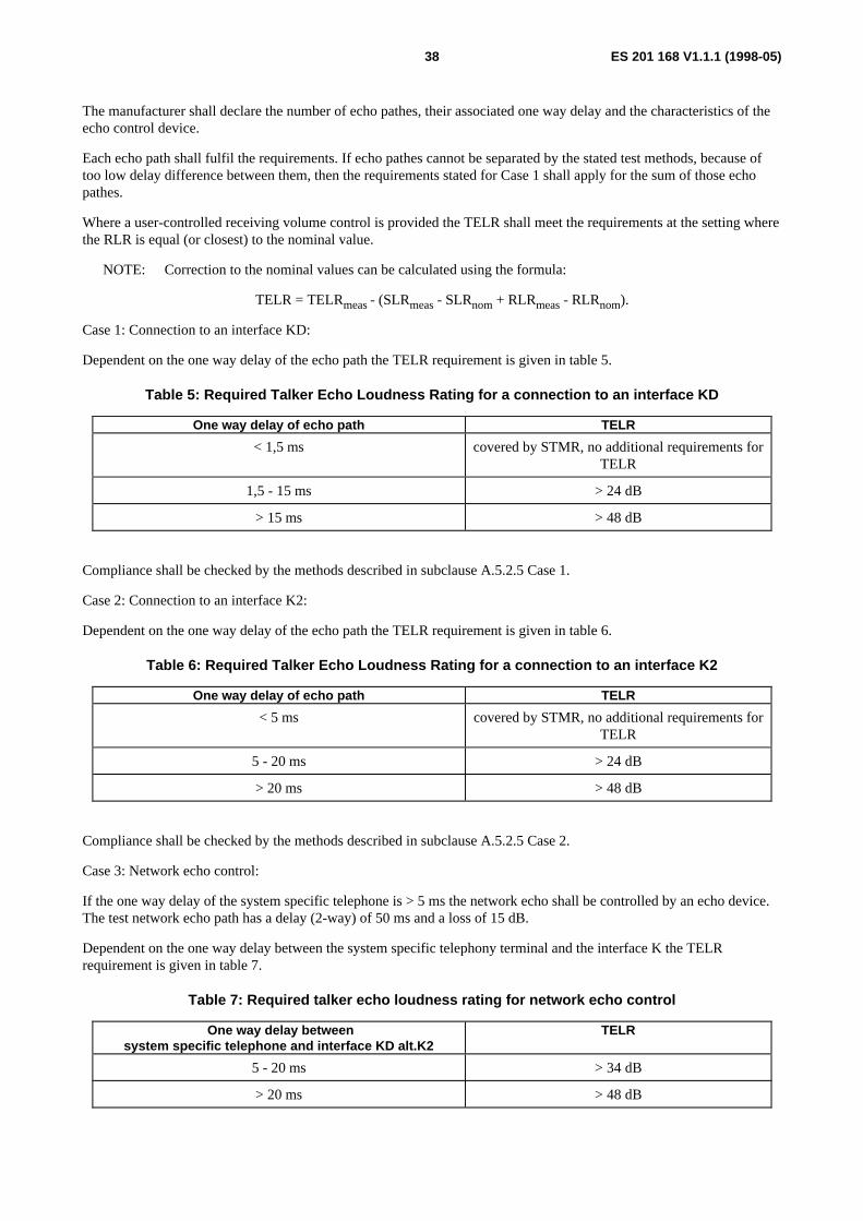
ES 201 168 V1.1.1 (1998-05)38
The manufacturer shall declare the number of echo pathes, their associated one way delay and the characteristics of theecho control device.
Each echo path shall fulfil the requirements. If echo pathes cannot be separated by the stated test methods, because oftoo low delay difference between them, then the requirements stated for Case 1 shall apply for the sum of those echopathes.
Where a user-controlled receiving volume control is provided the TELR shall meet the requirements at the setting wherethe RLR is equal (or closest) to the nominal value.
NOTE: Correction to the nominal values can be calculated using the formula:
TELR = TELRmeas - (SLRmeas - SLRnom + RLRmeas - RLRnom).
Case 1: Connection to an interface KD:
Dependent on the one way delay of the echo path the TELR requirement is given in table 5.
Table 5: Required Talker Echo Loudness Rating for a connection to an interface KD
One way delay of echo path TELR
< 1,5 ms covered by STMR, no additional requirements forTELR
1,5 - 15 ms > 24 dB
> 15 ms > 48 dB
Compliance shall be checked by the methods described in subclause A.5.2.5 Case 1.
Case 2: Connection to an interface K2:
Dependent on the one way delay of the echo path the TELR requirement is given in table 6.
Table 6: Required Talker Echo Loudness Rating for a connection to an interface K2
One way delay of echo path TELR
< 5 ms covered by STMR, no additional requirements forTELR
5 - 20 ms > 24 dB
> 20 ms > 48 dB
Compliance shall be checked by the methods described in subclause A.5.2.5 Case 2.
Case 3: Network echo control:
If the one way delay of the system specific telephone is > 5 ms the network echo shall be controlled by an echo device.The test network echo path has a delay (2-way) of 50 ms and a loss of 15 dB.
Dependent on the one way delay between the system specific telephony terminal and the interface K the TELRrequirement is given in table 7.
Table 7: Required talker echo loudness rating for network echo control
One way delay betweensystem specific telephone and interface KD alt.K2
TELR
5 - 20 ms > 34 dB
> 20 ms > 48 dB
ES 201 168 V1.1.1 (1998-05)39
Compliance shall be checked by the methods described in subclause A.5.2.5 Case 3.
7.2.6 Stability loss
With the handset lying on and the transducers facing a hard surface, the attenuation from the input test point to theoutput test point shall be at least a value stated by the supplier at all frequencies in the range 200 Hz to 3 600 Hz.
NOTE: see also subclause 8.5.
Compliance shall be checked by the methods described in subclause A.5.2.6.
7.2.7 Distortion
The supplier shall state the used coding scheme used for the system specific cordless telephony terminal. Thisinformation is required for transmission planning.
NOTE 1: The requirements for sending and receiving distortion apply only for wired system specific telephonyterminals.
NOTE 2: In the case of cordless telephones, the coding at the air interface is in most cases different from the codingscheme used by the system itself. The summation effect of distortion products arising from differentcoding schemes is not easily predictable in an unambiguous way, and may thus give unreliable results. Itcan be assumed that most cordless system specific telephony terminals will be based on some standardizedcoding scheme with given requirements for distortion, which the cordless equipment will meet in a stand-alone configuration.
7.2.7.1 Sending
The system specific telephony terminal shall meet the requirements of one of the subclauses 7.2.7.1.1 or 7.2.7.1.2.
7.2.7.1.1 Method 1 (Pseudo random noise stimulus)
The test signal shall consist of a band-limited noise signal conforming to CCITT Recommendation O.131 [16]. The ratioof signal-to-total distortion (harmonic and quantizing) power of the digitally encoded signal output by the systemspecific telephony terminal shall lie above the limits shown in figure 16 unless the sound pressure at the MRP is greaterthan +5 dBPa.
Compliance shall be checked by the methods described in subclause A.5.2.7.1.1.
7.2.7.1.2 Method 2 (Sinusoidal test signal)
The test signal shall be a sine-wave with a frequency in the range 1 004 Hz to 1 025 Hz. The ratio of signal-to-totaldistortion (harmonic and quantizing) power of the digitally encoded signal output by the system specific telephonyterminal, when passing through a noise weighting as specified in table 4 of CCITT Recommendation G.223 [9], shall lieabove the limits shown in figure 17 unless the sound pressure at the MRP is greater than +10 dBPa.
Compliance shall be checked by the methods described in subclause A.5.2.7.1.2.
7.2.7.2 Receiving
The system specific telephony terminal shall meet the requirements of one of the subclauses 7.2.7.2.1 or 7.2.7.2.2.
7.2.7.2.1 Method 1 (Pseudo random noise stimulus)
The test signal shall consist of a band-limited noise signal conforming to CCITT Recommendation O.131 [16]. The ratioof signal-to-total distortion (harmonic and quantizing) power of the signal in the artificial ear shall lie above the limitsshown in figure 18 unless the signal in the artificial ear is greater than +5 dBPa or is less than -50 dBPa.
Compliance shall be checked by the methods described in subclause A.5.2.7.2.1.
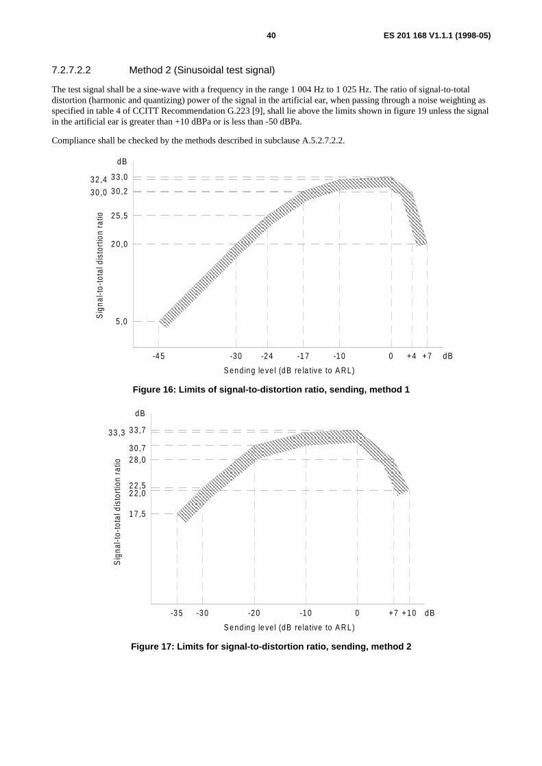
ES 201 168 V1.1.1 (1998-05)40
7.2.7.2.2 Method 2 (Sinusoidal test signal)
The test signal shall be a sine-wave with a frequency in the range 1 004 Hz to 1 025 Hz. The ratio of signal-to-totaldistortion (harmonic and quantizing) power of the signal in the artificial ear, when passing through a noise weighting asspecified in table 4 of CCITT Recommendation G.223 [9], shall lie above the limits shown in figure 19 unless the signalin the artificial ear is greater than +10 dBPa or is less than -50 dBPa.
Compliance shall be checked by the methods described in subclause A.5.2.7.2.2.
5,0
2 0,0
2 5,5
3 0,232 ,4 3 3,0
dB
-4 5 -30 -24 -1 7 -10 0 +4 + 7
Sig
nal-t
o-to
tal d
isto
rtio
n ra
tio
S en d ing le ve l (dB re la tive to A R L)
dB
30 ,0
Figure 16: Limits of signal-to-distortion ratio, sending, method 1
3 0,7
3 3,733 ,3
2 2,5
1 7,5
-3 5 -3 0 -20 -10 0 +7 +10 dB
dB
S e nd ing le ve l (dB re la tive to A R L)
Sig
nal-t
o-to
tal d
isto
rtio
n ra
tio
2 2 ,0
2 8,0
Figure 17: Limits for signal-to-distortion ratio, sending, method 2

ES 201 168 V1.1.1 (1998-05)41
33 ,0 3 3,7
3 0,6
2 5,5
2 0,0
5 ,0
-5 5 -40 -34 -2 7 -20 -10 -6 -3
R ece iv ing leve l a t the test po in t
Sig
nal-t
o-to
tal d
isto
rtio
n ra
tio
dB
dB m 0
30,0
Figure 18: Limits of signal-to-distortion ratio, receiving, method 1
1 7,5
2 2,5
3 0,5
3 3,533 ,0
dB
-4 5 -4 0 -30 -20 -10 -3 0 dB m0
R ece iv ing leve l a t the tes t po in t
Sig
nal-t
o-to
tal d
isto
rtion
ratio
2 2 ,0
2 8,0
Figure 19: Limits for signal-to-distortion ratio, receiving, method 2
7.2.7.3 Sidetone distortion
The third harmonic distortion generated by the system specific telephony terminal shall not be greater than 10 %.
Compliance shall be checked by the methods described in subclause A.5.2.7.3.
7.2.8 Variation of gain with input level
7.2.8.1 Sending
The gain variation relative to the gain for Acoustic Reference Level (ARL) shall be within the limits shown in figure 20.The test signal shall be a sine-wave with a frequency in the range 1 004 Hz to 1 025 Hz.

ES 201 168 V1.1.1 (1998-05)42
+13
0
-30-40
InputleveldB re l. to A R L
-2
dB
Var
iatio
n of
gai
n
-45 + 4-2 0
-5
-11
+ 1
+ 6
Figure 20: Variation of gain with input level (sending)
Compliance shall be checked by the methods described in subclause A.5.2.8.1.
7.2.8.2 Receiving
The gain variation relative to the gain at an input level of -10 dBm0 shall be within the limits shown in figure 21. Thetest signal shall be a sine-wave with a frequency in the range 1 004 Hz to 1 025 Hz.
+ 3-6-50
Inputlev eldB m 0
-2
+ 1
dB
Var
iatio
n of
gai
n
-10
-11
Figure 21: Variation of gain with input level (receiving)
Compliance shall be checked by the methods described in subclause A.5.2.8.2.
7.2.9 Out-of-band signals
These requirements do not apply for the analogue (wired) system specific telephony terminal.

ES 201 168 V1.1.1 (1998-05)43
7.2.9.1 Discrimination against out-of-band input signals (sending)
With any sine-wave signal between 4,6 kHz and 8 kHz applied at the MRP at a level of -4,7 dBPa, the level of anyimage signal in the frequency range 300 Hz to 3,4 kHz produced at the output test point shall be less than a referencelevel obtained at 1 kHz (-4,7 dBPa at MRP) by at least the amount (in dB) described in figure 22.
40
30
dB
Min
imum
lim
it
4 54 ,6 6 7 8 9 10 kH z
A pp lied s ine wave frequency (f) [loga rithm ic sca le ]
Figure 22: Discrimination levels (sending)
Compliance shall be checked by the methods described in subclause A.5.2.9.1.
7.2.9.2 Spurious out-of-band signals (receiving)
With a digitally simulated sine-wave signal in the frequency range of 300 Hz to 3,4 kHz and at a level of -10 dBm0applied at the input test point, the level of spurious out-of-band image signals in the frequency range of 4,6 kHz to 8 kHzmeasured selectively in the artificial ear shall be less than the in-band acoustic level produced by a digital signal at1 kHz set at the level described in figure 23 for wired or cordless system specific telephony terminals, respectively.
4 4 , 6 5 7 8 9 1 0 k H z 6
I m a g e s i g n a l f r e q u e n c y ( f ) [ l o g a r i t h m i c s c a l e ]
- 4 5
- 5 5
d B m 0
- 3 5
w i r e d
c o r d l e s s
Equ
ival
ent i
nput
sig
nal l
evel
Figure 23: Discrimination levels (receiving)
Compliance shall be checked by the methods described in subclause A.5.2.9.2.
ES 201 168 V1.1.1 (1998-05)44
7.2.10 Noise
If the transmission system between the telephony terminal and the PBX contains analogue elements, the noise in sendingand/or receiving direction shall not exceed a level which is 3 dB higher than the respective levels defined in subclauses7.2.10.1 and 7.10.2.
7.2.10.1 Sending
The noise in the sending direction shall not exceed (64 + SLRnom -7) dBm0p.
Compliance shall be checked by the methods described in subclause A.5.2.10.1.
7.2.10.2 Receiving
The noise in the artificial ear contributed by the receiving equipment alone shall not exceed -57 dBPa (A) when drivenby a PCM signal corresponding to the decoder output value number 1.
Compliance shall be checked by the methods described in subclause A.5.2.10.2.
7.2.10.3 Level of sampling frequency (receiving)
The level of 8 kHz measured selectively in the artificial ear shall be less than -70 dBPa.
This requirement does not apply for the analogue (wired) system specific telephony terminal.
Compliance shall be checked by the methods described in subclause A.5.2.10.3.
8 Characteristics for connections between twointerfaces
8.1 GeneralInformation about performance when interconnecting two interfaces applies only where this interconnection is intended,and when the interfaces are interconnected via the switch matrix. These interfaces can be electrical or acousticinterfaces.
NOTE: The information in this clause is mainly for the benefit of transmission planners.
8.2 Transmission loss between interfacesThe value of transmission loss between interfaces shall be stated by the supplier.
NOTE: In the case of system specific telephony terminals this includes also the values for SLR and RLR.
8.3 Quantizing distortion units (qdu)Where qdu is not relevant e.g. in case of none waveform coders the information regarding distortion shall be given interms of an equipment impairment factor Ie.
NOTE 1: More information about qdu and Ie-value is given in ETR 250.
NOTE 2: The number of qdu is 1 between two analogue interfaces if no digital loss pad is introduced in theconnection, or if the digital pad has a value equal to 6 dB (20*log(2) = 6,02 dB).

ES 201 168 V1.1.1 (1998-05)45
8.4 Mean one-way transmission timeThe mean one way transmission time in a connection between two interfaces including the acoustic interfaces of systemspecific telephones shall be a value stated by the supplier.
8.5 Stability loss
8.5.1 Stability loss of interfaces connected to a KD interface
The nominal stability loss of connections to a KD interface shall be at least 6 dB at all frequencies in the range 200 Hzto 3 600 Hz, when measured from the input of the KD interface to the output of the KD interface. However, where thenational transmission plan ensures that extra loss is added in the public network for international calls, the stability lossvalue in this clause shall be reduced by the value of such extra loss.
Termination of 2-wire interfaces connected to KD shall be as specified in subclause 5.9.2. Termination of a systemspecific telephony terminal interface connected to KD shall be as specified in subclause 7.2.5.
8.5.2 Stability loss of interfaces connected to M4 or MD interfaces
The nominal stability loss of connections to M4 or MD interfaces shall be at least a value stated by the supplier at allfrequencies in the range 200 Hz to 3 600 Hz, when measured from the input of the M4 or MD interface to the output ofthe M4 or MD interface. Termination of 2-wire interfaces connected to M4 or MD shall be as specified insubclause 5.9.2. Termination of a system specific telephony terminal interface connected to M4 or MD shall be asspecified in subclause 7.2.5.
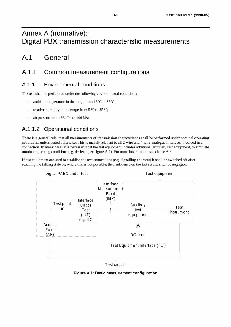
ES 201 168 V1.1.1 (1998-05)46
Annex A (normative):Digital PBX transmission characteristic measurements
A.1 General
A.1.1 Common measurement configurations
A.1.1.1 Environmental conditions
The test shall be performed under the following environmental conditions:
- ambient temperature in the range from 15°C to 35°C;
- relative humidity in the range from 5 % to 85 %;
- air pressure from 86 kPa to 106 kPa.
A.1.1.2 Operational conditions
There is a general rule, that all measurements of transmission characteristics shall be performed under nominal operatingconditions, unless stated otherwise. This is mainly relevant to all 2-wire and 4-wire analogue interfaces involved in aconnection. In many cases it is necessary that the test equipment includes additional auxiliary test equipment, to simulatenominal operating conditions e.g. dc-feed (see figure A.1). For more information, see clause A.3.
If test equipment are used to establish the test connections (e.g. signalling adapters) it shall be switched off afterreaching the talking state or, where this is not possible, their influence on the test results shall be negligible.
D ig ita l P ABX unde r test
In te rfaceU nderTest(IU T)
e .g . K2AccessPoin t(AP)
Test po in t
In te rfaceM easu rem en t
P o in t(IM P)
Auxilia rytest
equ ipm en t
Testinstrum en t
Test c ircu it
Test equ ipm en t
D C -feed
Test Equ ipm en t In te rface (TE I)
Figure A.1: Basic measurement configuration
ES 201 168 V1.1.1 (1998-05)47
A.1.2 Digital signal processingAll digital signal processing devices, which affect bit integrity of the 64 kbit/s speech-path within a digital PBX, e.g.digital loss or gain, digital echo control devices etc., shall be rendered inoperative, when measuring the transmissionparameters of the present document. However, if the NL is implemented by a digital loss or gain, the parameters"Nominal value" and "Tolerance" of the relative levels for input and output connections shall be measured with digitalloss or gain switched operative (see also clause 4).
A.1.3 Reference frequencyThe reference frequency shall be 1 020 Hz for test frequency generating circuits or instruments, that provide referencetest frequencies. The specified frequency tolerance shall be +2 Hz to -7 Hz.
A.1.4 ImpedanceUnless otherwise specified, measurements at analogue interfaces shall be made under matched conditions to the nominalimpedance Zr of the Interface Under Test (IUT). The interpretation of this statement is, that the nominal PBXimpedance is used as the internal impedance of the test signal generator and the analogue level meter, i.e. testinstruments with integrated test impedances.
NOTE: For more flexibility it may be preferable to use a low-impedance generator and a high-impedance meter inconjunction with a suitable external test impedance, which corresponds to an exact matching to thenominal PBX impedance.
A.1.5 Measurement pointsAs far as analogue 2-wire or 4-wire interfaces are considered, the Interface Measurement Point (IMP) shall be at the firstpoint of isolation as indicated by the PBX supplier, which provides testing access to the PBX and all external cabling.This means, that all cabling between this point and the interface card in the system, are included in the test results.
NOTE: For the test point used in conjunction with input/output-measurements and its access, see subclause 3.1.2.
A.1.6 Test InstrumentsFor the choice of test instruments the following features shall be considered:
The test instrumentation consists of the following four functional units:
- an analogue signal generator A to apply test signals to the IMP of the PBX under test e.g. via an auxiliary testequipment (see also subclause A.1.5 and clause A.3). For more information, see subclause 3.2 of ITU-TRecommendation O.133 [18];
- an analogue signal analyser B to process received signals from the IMP of the PBX under test e.g. via anauxiliary test equipment (see also subclause A.1.5 and clause A.3). For more information, see subclause 3.3 ofITU-T Recommendation O.133 [18];
- a digital signal generator C to apply test-signals to the Access Point (AP) or the Test Equipment Interface (TEI)of the PBX under test (see also clause A.2). For more information, see subclause 3.4 of ITU-TRecommendation O.133 [18];
- a digital signal analyser D to process signals received from the AP or the TEI of the PBX under test (see alsoclause A.2). For more information, see subclause 3.5 of ITU-T Recommendation O.133 [18].
As a general objective the accuracy of the test instruments shall be an order of magnitude better than the relevantperformance limits of the PBX under test.
In some cases it may not be possible to meet this objective due to technical and cost limitations.
For guidance to the capability and the accuracy of the test instrumentation refer to annex B.
ES 201 168 V1.1.1 (1998-05)48
A.1.7 Test levelsAt the reference frequency, test levels at analogue interfaces are defined in terms of apparent power relative to 1 mW.
Where no value is given, the test level shall be -10 dBm0. However, test levels may be restricted to a maximum absoluteinput and output power level as stated by the supplier.
At frequencies different from the reference frequency, test levels are defined as having the same voltage as the test levelat the reference frequency. Measurements are based on the use of a test generator with a frequency independent electromotive force (emf).
A.1.8 Disturbing effectsWhere the digital input of the test point is not used, a quiet code shall be applied.
Measurements, which involve low output signal levels, or when measuring individual spectral components of a signal,shall be performed using frequency selective equipment. A bandwidth of 80 Hz is recommended.
A.1.9 Alternative test methodsLaboratories may use other test methods provided they are electrically equivalent to those specified in the presentdocument.
Where the supplier requests other test methods as described in this annex the supplier shall provide sufficientinformation about how to perform such tests.
A.2 Test point and access to the test point
A.2.1 Basic principleIn the present document, most of the parameters specified are for input half connections and output half connections. Inthese cases the parameters are referred to a "test point" as given in subclause 3.1.2.1 and figure 3. However, this is onlya virtual point for specification purposes and might be considered as a "reference point".
For measurements, one or more specific AP shall be available to provide a suitable "path" between the test instrumentand the test point. In this path, a part, or all of the switching network will be included. To ensure, that the influence onthe results of this path is negligible, bit integrity is required.
NOTE: This physical access to the test point might be advantageous also for maintenance purposes. However,there is no obligation to provide AP on production systems in the field.
A.2.2 Physical nature of test accessFor measurement purposes, an AP shall be digital in its nature. To avoid additional adaptation equipment between APand test instrument, the following interface types shall be used with the test access:
- 64 kbit/s co-directional, according to clause 1 of CCITT Recommendation G.703 [10];
- 2 048 kbit/s, according to clause 6 of CCITT Recommendation G.703 [10];
- 192 kbit/s, according to CCITT Recommendation I.430 [13].
The synchronization of the test instrument from the digital PBX under test shall be ensured.
The coding law of the test point shall be either A-law or µ-law according to CCITT Recommendation G.711 [11].
NOTE: A-law is preferred.

ES 201 168 V1.1.1 (1998-05)49
A.2.3 Set-up of test connectionsMeasurements of half connections are normally performed such that a complete bi-directional connection between theAP, via the test point (switching matrix) and the IUT is established.
It is the responsibility of the supplier to make it possible to measure all specified input and output parameters as given inthe present document for all types of interfaces provided by the PBX such as K, L and M. Furthermore, it shall bepossible to perform conformance tests in every connection configuration of the tested interfaces, where such aconnection alters the transmission parameters.
Due to these facts, it might be necessary in some cases, to provide an additional software support for the control of testconnections. For test laboratories, documentation, which gives instructions for use of the test access, shall be madeavailable.
A.3 Auxiliary test equipment
A.3.1 GeneralAs already mentioned in subclause A.1.1.2, measurements shall be performed as far as possible under nominal operatingconditions. For this purpose, test feeding bridges in conjunction with a separate dc power supply and hold circuits areused at analogue interfaces, not only to keep the measured connection in the talking state, but also to provide a dcflowing, since the transmission characteristics of interfaces may vary with dc.
Furthermore, some modern test instruments (see subclause A.1.6) may only consist of an analogue or digital signalgenerator and signal receiver, but may not include additional bridge circuits as necessary, e.g. for return lossmeasurements. In those cases, external equipment shall be used in conjunction with the main PCM test instrument.Where artificial cables are included in the test circuit their characteristics shall be defined and standardized.
Every auxiliary test equipment which is part of the test circuit, shall have negligible influence on the test results.
NOTE: The values of inductances and capacitances used in auxiliary test equipment, may be sufficient formeasurements with nominal input or test impedances of 600 Ω resistive, but not for all capacitive compleximpedances.
Considering all these facts, the following subclauses will give minimum requirements for all important auxiliary testequipment, to ensure, that their influence on the test results is negligible.
A.3.2 dc power supplyIf dc power supply units are used in conjunction with a feeding bridge as part of the test circuit, any superimposed noisevoltage shall have negligible influence on the test results. More information is given in the relevant subclauses ofclause A.4.
A.3.3 Transmission Decoupling Unit (TDU)A TDU is used to either feed a dc into the appropriate analogue 2-wire point of the system under test, or to provide a dcloop.
The basic circuit of a TDU is shown in figure A.2. The realization shall provide also a negligible influence when used incommon mode configuration as necessary for impedance unbalance measurements, in conjunction with earthed dcpower supply.
If TDUs with active elements are used, linearity over the full range of test signal level and the respective noiseperformance shall be taken into account.

ES 201 168 V1.1.1 (1998-05)50
a AC
b AC b D C
D CaC a
C b
L b L a
C p
R F(note 1 )
R H C(note 2)+ -
D C supp ly(no te 3)
ToIn te rfaceU nder Test
Totestinstrum en t
+ -
NOTE 1: The value of the resistor RF is the value quoted for the nominal resistance of the feeding arrangementsbeing used. The actual value of RF is adjusted to allow for the resistance value of inductors La and Lb.
NOTE 2: The variable resistor RHC should be adjustable to give the required range of holding resistance. RHCshould allow for the resistances of inductors La and Lb.
NOTE 3: The dc supply should be such, that the full range of dc to be tested can be achieved. This could be by useof a low impedance dc voltage source in series with a variable resistor which replaces RF or a variableconstant current source.
Figure A.2: Basic circuit diagram of a Transmission Decoupling Unit (TDU)
The following characteristics of a TDU have to be considered as minimum requirements and shall be met over the fullrange of dc.
NOTE 1: Measurements of the following high values for a single TDU, mainly return loss and insertion lossrequirements in the full dc range may be difficult or impossible. Therefore, it is recommended to connecttwo TDUs of the same type in a suitable configuration and perform the measurements including bothTDUs. In this case, the requirements for insertion loss is 1,0 dB and 0,1 dB respectively and for returnloss 6 dB less than the following values for a single TDU.
Return loss: ≥ 33 dB in the range from 200 Hz to < 500 Hz
≥ 40 dB in the range from 500 Hz to < 2 500 Hz
≥ 33 dB in the range from 2 500 Hz to 4 000 Hz
measured with reference to a capacitive complex impedance (see annex E).

ES 201 168 V1.1.1 (1998-05)51
Insertion loss: for 50 Hz to 200 Hz < 0,5 dB
for 200 Hz to 4 000 Hz < 0,05 dB
for 4 000 Hz to 72 kHz < 0,5 dB
Together with earthed dc power supply a TDU shall meet the following inherent balance requirements:
Inherent balance: for 50 Hz to 20 kHz: LCL and LCTL ≥ 60 dB
for 200 Hz to 3 400 Hz: LCL and LCTL ≥ 75 dB
measured according to figures 1 and 3 of CCITT Recommendation O.9 [14], with respect to the bridged leads "+" and"-" of the TDU.
A.3.4 External hybrid for return loss measurementsThe hybrid shown in figure A.3 may be used for return loss measurements at 2-wire and 4-wire analogue ports.
S1
2
LM
R 1
R 2
SO
Z a
Z r
R1, R2 Resistors in the range from 100 Ω to 800 Ω (preferably 600 Ω), matched to each other ≤ 0,2 %.
S Switch (for the use of this switch see clause A.4).
SO Sinusoidal oscillator, output balanced, earth free, low impedance: ≤ 10 Ω.
LM Level meter, input balanced, earth free, high impedance ≥ 20 kΩ.
Zr Connection point for reference impedance test network.
Za Connection point to item under test.
Figure A.3: Return Loss measuring Hybrid (RLH)
If the above mentioned values are met, then the inherent return loss in the frequency range from 200 Hz to 4 000 Hz ofsuch an arrangement is more than 45 dB. For the purpose of testing the accuracy of such an equipment, values of600 Ω ± 0,1 % each are recommended for Zr and Za.
A.3.5 Test Equipment Interface (TEI)The interface of the test equipment connected to the digital IUT shall be capable of providing the signalling andsupervision necessary for the PBX to be working in all test modes.

ES 201 168 V1.1.1 (1998-05)52
A.4 Specific measurements
A.4.1 General procedure for measurement arrangementsConnect the IUT, using the arrangements for the measurement to be performed as specified in the appropriate subclausebelow, to both the IMP and the AP for half connection measurements.
For interfaces which have an external dc feed, the TDU shall have a suitable dc supply connected to the + / - terminals.
For interfaces which have an internal dc feed, the TDU shall have a suitable variable resistor connected tothe + /- terminals.
For interfaces which have no dc requirements being alternating current (ac) only circuits, the + / - terminals are shortcircuits or the TDU is not used.
Set the connection to the test point from the IUT such, that the connection case to be validated is established as detailedin the instructions provided for test purposes.
In setting up this connection, any signalling protocols which are necessary between the IUT and external connections,shall be exercised to ensure the correct conditioning of the IUT prior to the commencement of testing.
For IUTs which use in-band signalling this shall be disabled where it will interfere with the measurement beingperformed.
For those IUTs with dc, repeat the measurement for a representative series of dc values, which cover the range of dcwhich the IUT is expected to handle.
Set the connection between the test point and the AP for half connection measurements and between two IUTs for fullconnection measurements.
When testing a 4-wire interface, the input or output connection which is not used in the measurement being carried out,shall be terminated in its nominal impedance Zr.
NOTE: For the relationship between dBr, dBm, dBm0 and correction factors, reference may be made to annex C.
Perform the measurement in the specified manner and check the results against the values or limits laid down in thepresent document.
A.4.2 Analogue interfaces, half connection measurements
A.4.2.1 Input connections
A.4.2.1.1 Input transmission loss / input short-term variation of loss with time
a) Connect the IMP and the AP as shown in figure A.6 for 2-wire interfaces and figure A.7 for 4-wire interfaces,where:
A = signal generator (sine-wave);
C = digital signal generator;
D = digital level measuring instrument.
b) Set A at the IMP to provide the input level of - 10 dBm0 as stated for the IUT at a frequency of 1 020 Hz.
c) Measure the output level at the AP on D and record the value.
ES 201 168 V1.1.1 (1998-05)53
A.4.2.1.2 Input variation of gain with input level
a) Connect the IMP and the AP as shown in figure A.6 for 2-wire interfaces and figure A.7 for 4-wire interfaces,where:
A = signal generator (sine-wave);
C = digital signal Generator;
D = digital level measuring instrument (frequency selective).
b) Set A at the IMP to provide a representative series of input levels in the range specified in the present documentat a frequency of 1 020 Hz.
Set C at the AP to input a quiet code (see subclause A.1.8).
NOTE: To avoid overloading the codec, it may be necessary to perform this test using the actual input relativelevel of the interface as required in subclause 5.2.
c) Measure the output level at the AP on D and record the value for each input level used.
A.4.2.1.3 Input loss distortion with frequency
a) Connect the IMP and the AP as shown in figure A.6 for 2-wire interfaces and figure A.7 for 4-wire interfaces,where:
A = signal generator (sine-wave);
C = digital signal generator;
D = digital level measuring instrument.
b) Set A at the IMP to provide the input level of - 10 dBm0 as stated for the IUT at a representative series offrequencies in the range specified in the present document. One of the frequencies used for measurement shall bethe reference frequency 1 020 Hz.
c) Measure the output levels at the AP on D and record the value for each input frequency used.
A.4.2.1.4 Input total distortion including quantizing distortion
a) Connect the IMP and the AP as shown in figure A.6 for 2-wire interfaces and figure A.7 for 4-wire interfaces,where:
A = signal generator (sine-wave);
C = digital signal generator;
D = digital level measuring instrument.
A and D shall form part of the same instrument, which shall be capable of performing total distortionmeasurements.
b) Set A at the IMP to provide a representative series of input levels in the range specified in the present documentat a frequency of 1 020 Hz.
Set C at the AP to input a quiet code (see subclause A.1.8).
c) Measure the total distortion and record the value for each input level used.
A.4.2.1.5 Discrimination against out-of-band signals applied to the input interface
a) Connect the IMP and the AP as shown in figure A.6 for 2-wire interfaces and figure A.7 for 4-wire interfaces,where:
ES 201 168 V1.1.1 (1998-05)54
A = signal generator (sine-wave 4,6 kHz to 72 kHz);
C = digital signal generator;
D = digital level measuring instrument.
b) Set A at the IMP to provide an input level of -25 dBm0 as stated for the IUT at a representative series offrequencies in the range specified in the present document.
Set C at the AP to input a quiet code (see subclause A.1.8).
c) Measure the output levels at the AP on D and record the value for each input frequency used. If the result is lessthan 25 dB below the input level of the test signal when D is in the voice frequency bandwidth mode, thenindividual spectral frequency measurements shall be performed to determine compliance.
NOTE: See subclause A.1.8 for information on frequency selective measurements.
A.4.2.2 Output connections
For these connections, D is required to enable synchronization of the test apparatus.
A.4.2.2.1 Output transmission loss / output short-term variation of loss with time
a) Connect the IMP and the AP as shown in figure A.8 for 2-wire interfaces and figure A.9 for 4-wire interfaces,where:
B = level measuring instrument;
C = digital signal generator;
D = digital level measuring instrument.
b) Set C at the AP to provide the input level of -10 dBm0 as stated for the IUT at a frequency of 1 020 Hz.
c) Measure the output level at the IMP on B and record the value.
A.4.2.2.2 Output variation of gain with input level
a) Connect the IMP and the AP as shown in figure A.8 for 2-wire interfaces and figure A.9 for 4-wire interfaces,where:
B = level measuring instrument (frequency selective);
C = digital signal generator;
D = digital level measuring instrument.
b) Set C at the AP to provide a representative series of input levels in the range specified in the standard at afrequency of 1 020 Hz.
c) Measure the output level at the IMP on B and record the value for each input level used.
A.4.2.2.3 Output loss distortion with frequency
a) Connect the IMP and the AP as shown in figure A.8 for 2-wire interfaces and figure A.9 for 4-wire interfaces,where:
B = level measuring instrument;
C = digital signal generator;
D = digital level measuring instrument.

ES 201 168 V1.1.1 (1998-05)55
b) Set C at the AP to provide an input level of -10 dBm0 as stated for the IUT at a representative series offrequencies in the range specified in the present document. One of the frequencies used for measurement shall bethe reference frequency 1 020 Hz.
c) Measure the output level at the IMP on B and record the value for each input frequency.
A.4.2.2.4 Output total distortion including quantizing distortion
a) Connect the IMP and the AP as shown in figure A.8 for 2-wire interfaces and figure A.9 for 4-wire interfaces,where:
B = level measuring instrument;
C = digital signal generator;
D = digital level measuring instrument.
C and B shall form part of the same instrument, which shall be capable of performing total distortion measurements.
b) Set C at the AP to provide a representative series of input levels in the range specified in the present document ata frequency of 1 020 Hz.
c) Measure the output total distortion and record the value for each level used.
A.4.3 Analogue interfaces impedance measurements
A.4.3.1 Return loss
Return loss may be determined by direct impedance measurements and calculation. Alternatively, return loss measuringhybrids as shown in figure A.3 may be used and the following measurement procedures carried out.
a) Connect the IMP and the AP as shown in figure A.10 for 2-wire interfaces and figure A.11 for 4-wire interfaces,where:
A = analogue signal generator (sine-wave, low impedance);
B = level measuring instrument (high input impedance > 20 kΩ);
C = digital signal generator;
D = digital level measuring instrument;
RLH = Return Loss Hybrid.
NOTE: The digital level measuring instrument D is required to enable synchronization of the test apparatus.
b) Set C to input a quiet code.
c) Connect the RLH to the IMP and terminate the leads Zr of RLH with the respective value as stated in thestandard for the IUT. Adjust the signal generator A to give an input level of -10 dBm0 at SO at a frequency of1 020 Hz.
d) Operate S of RLH to position 2 and adjust the level meter B to give a 0 dB reading.
e) Operate S of RLH to position 1.
f) Read off the return losses at the specified frequencies.
Some test instruments are providing the RLH as an integral part with a direct readout of return loss values. In thosecases the reference impedance Zr shall be connected to the respective sockets of the instrument and steps c) to e) are notapplicable.
g) For 4-wire interfaces connect the RLH to the output IMP and Zr to the input IMP, and repeat steps d) through f).

ES 201 168 V1.1.1 (1998-05)56
A.4.3.2 TBRL, stability
The measurement configurations for TBRL and stability are nearly similar. They only differ in the used termination atthe IMP. These measurements are only applicable to 2-wire interfaces.
a) Connect the AP as shown in figure A.12 where:
C = digital signal generator;
D = digital level measuring instrument.
b) Terminate the IMP with the nominal test network as specified for this type of interface when performing TBRLmeasurements. Terminate the IMP with either open or short circuit when performing stability measurements.
c) Set C at the AP to provide the input level of -10 dBm0 as stated for the IUT at a representative series offrequencies in the range specified in the present document.
d) Measure the output levels pout at the AP on D the digital level measuring instrument. Calculate the TBRL usingthe formula:
TBRL = -pout - Li + Lo - 10 [dB]
where Li and Lo are the nominal relative input and output levels of the IUT.
Calculate the stability loss using the formula:
stability loss = -pout - 10 [dB]
e) Record the result for each input frequency used.
A.4.4 Analogue interfaces, crosstalkReference shall be made to "the interfering half connection" (which is defined as that half connection which has the testsignal injected) and "the target half connection" (which is defined as the half connection at which the measurement ismade).
When considering those interfaces which require to be assessed for crosstalk examination, the physical proximity andgeographical relationship between interfaces shall be required. This shall be necessary to limit the number ofcombinations which are tested to acceptable levels.
To be able to carry out the crosstalk measurements access to two half connections at the same time shall be provided.Thus, if the AP is a single 64 kbit/s co-directional channel as mentioned in subclause A.2.2 (a), two such APs isrequired; if the AP is a multi-channel system as mentioned in subclause A.2.2 (b) and (c) two channels shall be capableof being used simultaneously.
Each access channel used shall be identified as Access Point Connection 1 (APC 1) and Access Point Connection 2(APC 2), respectively.
The half connections used in the crosstalk measurements shall be set up to be in the conversational state.
Measurements shall be carried out by use of a frequency selective level measuring instrument.
A.4.4.1 Input connections
A.4.4.1.1 Far End Crosstalk (FEXT)
a) Having determined the interfaces which are to be used as the interfering half connection and as the target halfconnection, connect the IMPs and the APs as shown in figure A.13 for 2-wire interfaces, in figure A.14 for4-wire interfaces and in figure A.15 for measurements between 4-wire and 2-wire interfaces, where:

ES 201 168 V1.1.1 (1998-05)57
A1, A2 = analogue signal generators (sine-wave);
C1, C2 = digital signal generators;
D1 = digital level measuring instrument.
b) Set A1 at the IMP of the target half connection, to provide a low-level activating signal.
NOTE 1: Suitable activating signals are, for example, a band limited noise signal (see CCITTRecommendation O.131 [16]) at a level in the range -50 dBm0 to -60 dBm0 or a sine-wave signal at alevel in the range -33 dBm0 to -40 dBm0.
NOTE 2: Care should be taken in the choice of frequency and the filtering characteristics of the measuringapparatus such that the activating signal does not significantly affect the accuracy of the crosstalkmeasurement.
c) Set C1 and C2 at the APs to input a quiet code (see subclause A.1.8).
d) Set A2 at the IMP of the interfering half connection, to provide a sine-wave test signal at the reference frequencyof 1 020 Hz at a level of 0 dBm0.
e) Measure the level of the 1 020 Hz sine-wave in D1 at the APC 1 of the target half connection, and record thevalue.
A.4.4.1.2 Near End Crosstalk (NEXT)
a) Having determined the interfaces which are to be used as the interfering half connection and as the target halfconnection, connect the IMPs and the APs as shown in figure A.13 for 2-wire interfaces, in figure A.14 for4-wire interfaces and in figure A.15 for measurements between 4-wire and 2-wire interfaces, where:
A2 = analogue signal generator (sine-wave);
B1 = analogue level measuring instrument;
C1, C2 = digital signal generators.
b) Set C1 and C2 at the APs, to input a quiet code (see subclause A.1.8).
c) Set A2 at the IMP of the interfering half connection, to provide a sine-wave test signal at the reference frequencyof 1 020 Hz at a level of 0 dBm0.
d) Measure the level of the 1 020 Hz sine-wave on B1 at the IMP of the target half connection, and record the value.
A.4.4.2 Output connections
A.4.4.2.1 Far End Crosstalk (FEXT)
a) Having determined the interfaces which are to be used as the interfering half connection and as the target halfconnection, connect the IMPs and the APs as shown in figure A.13 for 2-wire interfaces, in figure A.14 for4-wire interfaces and in figure A.15 for measurements between 4-wire and 2-wire interfaces, where:
B1 = analogue level measuring instrument;
C1, C2 = digital signal generators.
b) Set C1 at the APC 1 to input a quiet code (see subclause A.1.8).
c) Set C2 at the APC 2 to provide a digitally simulated sine-wave test signal at the reference frequency 1 020 Hz ata level of 0 dBm0.
d) Measure the level of the 1 020 Hz sine-wave on B1 at the IMP of the target half connection, and record the value.
ES 201 168 V1.1.1 (1998-05)58
A.4.4.2.2 Near End Crosstalk (NEXT)
a) Having determined the interfaces which are to be used as the interfering half connection and as the target halfconnection, connect the IMPs and the APs as shown in figure A.13 for 2-wire interfaces, in figure A.14 for4-wire interfaces and in figure A.15 for measurements between 4-wire and 2-wire interfaces, where:
A1 = analogue signal generators (sine-wave);
C1, C2 = digital signal generators;
D1 = digital level measuring instrument.
b) Set A1 at the IMP of the target half connection, to provide a low-level activating signal.
NOTE 1: Suitable activating signals are, for example, a band limited noise signal (see CCITT RecommendationO.131 [16]) at a level in the range -50 dBm0 to -60 dBm0 or a sine-wave signal at a level in the range-33 dBm0 to -40 dBm0.
NOTE 2: Care should be taken in the choice of frequency and the filtering characteristics of the measuringapparatus such that the activating signal does not significantly affect the accuracy of the crosstalkmeasurement.
c) Set C1 at the APC 1 to input a quiet code (see subclause A.1.8).
d) Set C2 at the APC 2 to provide a digitally simulated sine-wave test signal at the reference frequency 1 020 Hz ata level of 0 dBm0.
e) Measure the level of the 1 020 Hz sine-wave on D1 at the APC 1 of the target half connection, and record thevalue.
A.4.5 Analogue interfaces, noise measurements
A.4.5.1 Weighted noise measurements
The method described here is concerned with the measurement of the total noise at analogue interfaces. The total noiseis due to the noise generated by analogue sources, including the PBX power supply, together with noise arising from theencoding / decoding processes. The noise levels due to these sources are influenced by the design and complexity of theinterfaces and by the relative levels employed.
PBXs employ a number of different types of interface and the relative levels of a particular interface may vary with thetype of connection served. The resultant large number of possible interface connection combinations makes it difficult tocarry out noise measurements on complete connections. Half connection measurements are therefore preferred, and inthis case, the noise on both the analogue and digital sides of an interface shall be measured.
Measurements are made on the digital side of an interface (i.e. on an input connection) with a digital signal analyser.Analogue measurements on an output connection are made with an analogue signal analyser, which may be a simplepsophometer which conforms to the Recommendations of ITU-T Recommendation O.41 [15]. The digital signalanalyser selects a digital signal from any time slot and decodes it. In order to minimize errors the instrument's decodershall conform to the "ideal" as described in CCITT Recommendation G.711 [11].
The noise measurements are weighted psophometrically and measuring instruments shall incorporate the weightingfunction as described in ITU-T Recommendation O.41 [15]. Total psophometric power measurements are made and theminimum noise measuring range shall be -80 dBmp to -20 dBmp.
The analogue signal analyser shall have a virtually linear input impedance of 600 Ω as specified in ITU-TRecommendation O.41 [15]. The indicated noise levels are related to the psophometrically weighted noise powersdissipated in this impedance. The noise levels indicated by the digital signal analyser are also related to thepsophometrically weighted noise powers dissipated in 600 Ω.
ES 201 168 V1.1.1 (1998-05)59
Noise measurements shall be made with the interfaces terminated in impedances which match their output impedances.These impedances are usually complex and hence an impedance converter shall be connected between the terminatedinterface and the analogue signal analyser. The impedance converter shall present a very high input impedance to theinterface and a very low output impedance to the analyser.
A TDU shall be used when interfaces are required to carry line current. The TDU is used to supply this current or, toprovide a dc loop, as appropriate for the IUT. Adjustments to the internal components and / or to the TDU's powersupply are made to provide the nominal line current before noise measurements are carried out.
A.4.5.1.1 Input connections
a) Connect the IMP and the AP as shown in figure A.16 for 2-wire interfaces and figure A.17 for 4-wire interfaces,where:
C = digital signal generator;
D = digital signal analyser.
b) Set C to apply a quiet code (see subclause A.1.8).
c) Measure the weighted noise level on D and record the value.
A.4.5.1.2 Output connections
a) Connect the IMP and the AP as shown in figure A.18 for 2-wire interfaces and figure A.19 for 4-wire interfaces,where:
B = analogue signal analyser;
C = digital signal generator;
E = termination, appropriate to the type of digital test access interface used.
b) Set C to apply a quiet code (see subclause A.1.8).
c) Measure the weighted noise level on B and record the value.
The input and output relative levels of a measured interface shall be taken into account when assessing noiseperformance. Reference shall be made to subclause 5.4 of the present document to determine the permitted noise levels.
A significant amount of noise may be generated by the TDU, its associated power supply and by the impedanceconverter. The noise of the test circuit, including these auxiliary equipment, but without IUT shall be < -85 dBmp. Whenmeasuring the noise generated by the test circuit, the IUT shall be replaced by a resistor R with the same value as theinput dc resistance of the IUT. The resistor R is used to establish the appropriate current in the TDU. The noisecorrection for the TDU alone may be determined by removing the impedance converter and observing the indicatednoise across Zr with B connected directly to the TDU's output terminals.
A.5 Electro-acoustic measurements
A.5.1 General measurement arrangementAll measurements including a system specific telephony terminal, are performed between the acoustic interface of thetelephone handset and the digital test access point of the digital PBX under test. The telephony terminal is connected toits corresponding interface of the PBX and a connection is established between the telephony terminal under test and thetest AP. The general test configuration valid for all electro-acoustic measurements in clause A.5 is shown in figure A.20.
All measured values shall, where applicable, be corrected to the nominal values of SLR and RLR as stated by thesupplier.

ES 201 168 V1.1.1 (1998-05)60
Beside the general issues as given in clauses A.1 to A.3, some additional specifications, described in the followingsubclauses, shall be considered in conjunction with electro-acoustic measurements.
A.5.1.1 Electro-acoustic test equipment
The test equipment used for electro-acoustic measurements shall conform to ITU-T Recommendation P.64 [21], usingthe algorithm as described in ITU-T Recommendation P.79 [23].
The artificial mouth shall conform to ITU-T Recommendation P.51 [19].
The artificial ear shall conform to type 1 of the ITU-T Recommendation P.57 [20]. The supplier is permitted to requestthe use of a type 3.2 artificial ear of ITU-T Recommendation P.57 [20]. In this case the low leakage option of type 3.2artificial ear shall be adopted. If the geometry of the handset does not allow the use of the type 3.2 artificial ear, then thetype 3.3 artificial ear shall be used. The force against the ear shall be as specified in ITU-T Recommendation P.57 [20].Then the test results shall be corrected to ERP by the correction characteristic specified in ITU-T RecommendationP.57 [20]. When these artificial ears of type 3.2 or 3.3 are used, no leakage correction shall be made in the calculationsof RLR, SideTone Masking Rating (STMR) and LSTR (i.e. LE = 0).
A.5.1.2 Accuracy of test equipment
Unless specified otherwise, the accuracy of measurements made by test equipment shall be better than the values givenin table A.1.
Table A.1: Accuracy of measurements made by test equipment
Item AccuracyElectrical signal powerElectrical signal powerSound pressureTimeFrequency
± 0,2 dB for levels > -50 dBm± 0,4 dB for levels < -50 dBm± 0,7 dB± 5 %± 0,2 %
Unless specified otherwise, the accuracy of the signals generated by the test equipment shall be better than the valuesgiven in table A.2.
Table A.2: Accuracy of signals generated by test equipment
Quantity AccuracySound pressure level at MRP
Electrical excitation levelsFrequency generation
±1 dB for 200 Hz to 4 kHz±3 dB for 100 Hz to 200 Hzand 4 kHz to 8 kHz±0,4 dB (see note 1)±2 % (see note 2)
NOTE 1: Across the whole frequency range.NOTE 2: When measuring sampled systems, it is advisable to avoid measuring at
sub-multiples of the sampling frequency. There is a tolerance of ± 2 % onthe generated frequencies, which may be used to avoid this problem, exceptfor 4 kHz where only the -2 % tolerance may be used.
A.5.1.3 Ideal codec approach and specification
A.5.1.3.1 Codec approach
As an option, an ideal codec may be used to convert the companded digital input and output bitstream of the test accesspoint to the equivalent analogue values, so that existing test procedures, mainly for electro-acoustic measurements andequipments, without the ability to generate or analyse digital signals, can be used. This codec shall be a high qualitycodec, whose characteristics are as close as possible to ideal. The specification for such a codec is given below.

ES 201 168 V1.1.1 (1998-05)61
A.5.1.3.2 Codec specification
A practical implementation of an ideal codec may be called a reference codec (see clause 4 of ITU-T RecommendationO.133 [18]). For the reference codec, characteristics such as attenuation/frequency distortion, idle channel noise,quantizing distortion, etc., shall be better than the requirements specified in CCITT Recommendation G.712 [12], so asnot to mask the corresponding parameters of the set under test. A suitable reference codec may be realized by using:
- at least 14 bit linear A / D and D / A converters of high quality and transcoding the output signal to the A-lawPCM format;
- a filter response that meets the requirements of figure A.4.
3,03,6
3,4 4,0 kHz1,00,10,08
Frequency (f) [ logarithm ic scale]
-0,25
0
0,25
0,9
40dB
Loss
Figure A.4: Attenuation/frequency distortion of the sending or receiving sides of the reference codec
Definition of the analogue 0 dBr point:
D / A converter: a Digital Test Sequence (DTS) representing the PCM equivalent of an analogue sinusoidal signalwhose root mean square (rms) value is 3,14 dB (A-law) below the maximum full-load capacity ofthe codec, shall generate 0 dBm across a 600 Ω load;
A / D converter: a 0 dBm signal generated from a 600 Ω source, shall give the DTS representing the PCMequivalent of an analogue sinusoidal signal, whose rms value is 3,14 dB (A-law) below themaximum full-load capacity of the codec.
DTS is defined as a periodic sequence of character signals as defined in table 5 of CCITT Recommendation G.711 [11].
NOTE: For further information, see figure 6 of ITU-T Recommendation G.101 [3].
Analogue interface: The output and input impedances, return loss and longitudinal conversion losses of the analogueinterface of the reference codec shall be in accordance with subclause 3.1.1 of ITU-T Recommendation 0.133 [18].
Digital interface: The fundamental requirements for the reference codec digital interface are given in the appropriateCCITT Recommendations (e.g., CCITT Recommendation G. 703 [10]).
A.5.1.4 Selective measurements
It shall be the responsibility of the test house to select an appropriate bandwidth for selective measurements.

ES 201 168 V1.1.1 (1998-05)62
For single frequency noise measurements the procedures of subclauses A.4.5.1.1 and A.4.5.1.2 are followed with thedigital and analogue signal analysers in the frequency selective mode. Both in-band and out-of-band single frequencynoise components may then be measured.
A.5.1.5 Use of digital loss or gain pads
According to the rules given in clause 4, the use of digital loss or gain pads in the speech path shall be stated by thesupplier. If the pads are included in the path between test point of the PBX and system specific telephony terminal, thesepads shall be switched inoperative during all transmission measurement, with the exception of:
- SLR (see subclause A.5.2.2.1);
- RLR (see subclause A.5.2.2.2);
- Echo Loss (see subclause A.5.2.4);
- TELR (see subclause A.5.2.5);
- Stability loss (see subclause A.5.2.6).
Basically all transmission measurements in conjunction with a system specific telephony terminal, are performed only upto the test point of the PBX. If digital pads are included in the path between test point and the interface KD of the PBX(to be stated by the supplier), test results of SLR, RLR, EL and stability loss shall be corrected with the nominal valuesof the digital loss or gain pads in both transmission directions.
A.5.1.6 Use of echo control devices
If the supplier declares that an echo control device is needed in order to meet the requirements of the present documentit shall be switched operative if not otherwise stated.
A.5.1.7 Use of a Reference Portable Part (RPP)
In cases where the PBX supplier does not provide the PP of a cordless system but solely a standardized air interface thetransmission characteristics can be verified using a RPP.
The RPP shall provide the equivalent of true air interface measurements and therefore shall not contain circuitry whichwill modify the true air interface speech frequency performance. For measurement purposes, the RPP shall have a testaccess point as specified in relevant standards.
A.5.2 Specific electro-acoustic measurements
A.5.2.1 Sensitivity - frequency response
A.5.2.1.1 Sending
a) A connection shall be established between the telephony terminal under test and the digital test AP of the PBX.
b) The handset is mounted in the Loudness Rating Guard ring Position (LRGP) (see ITU-T RecommendationP.64 [21]). The earpiece is sealed to the knife-edge of an artificial ear.
c) A pure tone signal with a sound level of -4,7 dBPa, in accordance with ITU-T Recommendation P.64 [21] shallbe applied at the MRP as described in ITU-T Recommendation P.64 [21], using an artificial mouth conformingto ITU-T Recommendation P.51 [19].
d) A digital measuring instrument, or high quality digital decoder followed by an analogue level measuring set, shallbe connected at the digital test access point of the PBX.
e) Measurements shall be made at one-twelfth octave intervals as given by the R.40 series of preferred numbers inISO 3 [29] for frequencies from 100 Hz to 4 kHz inclusive.

ES 201 168 V1.1.1 (1998-05)63
f) At each frequency, the output level for a sound pressure of -4,7 dBPa shall be measured.
A.5.2.1.2 Receiving
a) A connection is established and the handset is mounted as described in subclause A.5.2.1.1.
b) A digital signal generator shall be connected at the digital test access point of the PBX, delivering a signalequivalent to a pure tone level of -16 dBm0 (see ITU-T Recommendation P.64 [21]).
c) Measurements shall be made at one twelfth-octave intervals as given by the R.40 series of preferred numbers inISO 3 [29] for frequencies from 100 Hz to 4 kHz inclusive.
d) At each frequency, the sound pressure in the artificial ear shall be measured by connecting a suitable measuringset to the artificial ear.
A.5.2.2 Loudness Ratings (LR)
A.5.2.2.1 Sending Loudness Rating (SLR)
a) The connection is established and the handset is mounted as described in subclause A.5.2.1.1. The sendingsensitivity shall be measured at each of the 14 frequencies given in table 1, bands 4 to 17 of ITU-TRecommendation P.79 [23].
b) The sensitivity is expressed in terms of dBV/Pa and the SLR shall be calculated according to formula 2.1, overbands 4 to 17 of ITU-T Recommendation P.79 [23] using m = 0,175 and the sending weighting factors fromtable 1 of ITU-T Recommendation P.79 [23].
NOTE: ITU-T Recommendation P.64 [21] allows the use of alternative signal sources for measurement of LRs. Ifsuch a signal source is used, it is the responsibility of the test house to ensure that the method used isequivalent to that described above.
A.5.2.2.2 Receiving Loudness Rating (RLR)
a) A connection is established and the handset is mounted as described in subclause A.5.2.1.1. The receivingsensitivity shall be measured at each of the 14 frequencies listed in table 1, bands 4 to 17, of ITU-TRecommendation P.79 [23].
b) The sensitivity is expressed in terms of dBPa/V and the RLR shall be calculated according to formula 2.1, overbands 4 to 17 of ITU-T Recommendation P.79 [23], using m = 0,175 and the receiving weighting factors fromtable 1 of ITU-T Recommendation P.79 [23].
c) The artificial ear sensitivity shall be corrected using the leakage correction of table 2 of ITU-T RecommendationP.79 [23].
NOTE: ITU-T Recommendation P.64 [21] allows the use of alternative signal sources for measurement of LRs. Ifsuch a signal source is used, it is the responsibility of the test house to ensure that the method used isequivalent to that described above.
A.5.2.3 Sidetone
For the tests described in subclauses A.5.2.3.1 and A.5.2.3.2, the digital input of the test access point shall be driven bya PCM signal corresponding to decoder value number 1.
A.5.2.3.1 Talker's sidetone
a) A connection is established and the handset is mounted as described in subclause A.5.2.1.1. A pure tone signal of-4,7 dBPa shall be applied at the MRP. For each frequency given in table 3, bands 1 to 20 of ITU-TRecommendation P.79 [23], the sound pressure in the artificial ear shall be measured.

ES 201 168 V1.1.1 (1998-05)64
b) Where a user controlled volume control is provided, the measurements shall be carried out at a setting, which isas close as possible to the declared nominal value of the RLR.
c) The Sidetone path loss (LmeST), expressed in dB, and the STMR, also expressed in dB, shall be calculated fromthe formula 2.1 of ITU-T Recommendation P.79 [23], using m = 0,225 and the weighting factors of table 3 ofITU-T Recommendation P.79 [23].
NOTE: ITU-T Recommendation P.65 [22] allows the use of alternative signal sources for measurement of LRs. Ifsuch a signal source is used, it is the responsibility of the test house to ensure that the method used isequivalent to that described above.
A.5.2.3.2 Listener's sidetone
a) The diffuse sound field is calibrated in the absence of any local obstacles. The averaged field shall be uniform towithin ± 3 dB within a radius of 0,15 m of the MRP, when measured in one-third octave bands according toIEC 61260 [27] from 100 Hz to 8 kHz (bands 1 to 20).
NOTE 1: The pressure intensity index, as defined in ISO/DIS 9614-1 [30], may prove to be a suitable method forassessing the diffuse field.
NOTE 2: Where more than one loudspeaker is used to produce the desired sound field, the loudspeakers mayrequire to be fed with non coherent electrical signals to eliminate standing waves and other interferenceeffects.
b) For measurement of LSTR a connection is established and the handset is mounted as described insubclause A.5.2.1.1.
c) Where a user controlled volume control is provided, the measurements shall be carried out at a setting which is asclose as possible to the declared nominal value of the RLR.
d) Where adaptive techniques or voice switching circuits are not used (need to be declared by the supplier), thespectrum of the diffuse sound field shall be a band limited "pink noise" (50 Hz to 10 kHz) according to annex Bof ITU-T Recommendation P.64 [21], to within ±3 dB and the level shall be adjusted to 70 dB(A)(-24 dBPa(A)). The tolerance for this level adjustment is ±1 dB. In other cases the level shall be adjusted to50 dB(A) (-44 dBPa(A)), with a tolerance of ±1 dB.
e) Measurements shall be made on one-third octave bands according to IEC 61260 [27] for the 20 bands centred at100 Hz to 8 kHz (bands 1 to 20). For each band the sound pressure in the artificial ear shall be measured byconnecting a suitable measuring set to the artificial ear.
NOTE 3: There may be problems with the signal to noise ratio. If it is less than 10 dB in any band, the microphonenoise level and the noise level of any out-of-band signals need to be subtracted from the measuredsidetone level (power subtraction).
f) The listener sidetone path loss is expressed in dB and the LSTR shall be calculated from formula 2.1 ofITU-T Recommendation P.79 [23], using m = 0,225 and the weighting factors in table 3 of ITU-TRecommendation P.79 [23].
g) For the weighted average D of the difference of the send sensitivities between diffuse and direct sound the diffusesound sensitivities measured as specified above shall be used for the calculation as Ssi(diff) at 14 bands from200 Hz to 4 kHz. The sending sensitivities for the direct sound Ssi (direct) shall be measured according tosubclause A.5.2.1.1, but at one-third octave bands for 14 bands centred at 200 Hz to 4 kHz with the pink noisetest signal as specified above. D is computed with Ssi(diff) and Ssi(direct) from the ITU-T RecommendationP.79 [23] formulas E-2 and E-3 and the coefficients Ki in table E.1/P.79.

ES 201 168 V1.1.1 (1998-05)65
A.5.2.4 Echo Loss at the interface KD
The test configuration is shown in figure A.20.
a) A connection is established between the system specific telephony terminal and the interface KD.
b) The handset is suspended in free air in such a way, that the inherent mechanical coupling of the handset is noteffected. The testing shall be made under free field condition (the deviation from ideal free field conditions shallbe less than 1 dB). The ambient noise level shall be less than 30 dB(A).
c) The attenuation from digital input to digital output of the interface KD shall be measured separately for eachecho path declared by the supplier, using a suitable pulsed test signal of band limited (300 Hz to 3400 Hz) pinknoise with a level of -10 dBm0.
d) The EL at the interface KD can be calculated by means of Fast Fourier Transformation (FFT) for the first echopath at the beginning of such a pulse of pink noise and for the second echo path at the end of it.
e) If the declared echo pathes cannot be separated by the method described before, then another method shall beapplied. With a suitable test signal, e.g. pink noise, the impulse response of the sum of the echo pathes shall berecorded. For each echo path the appropriate impulse response shall be separated in the time domain and then beretransformed to the frequency domain.
f) Finally the EL is calculated according to ITU-T Recommendation G.122 [6].
If no interface KD is available for testing, the tests should be made between the system specific terminal and the testaccess point. In this case the sum of the losses in both directions of the path „test point to interface KD" shall be addedto the measured value.
A.5.2.5 Talker Echo Loudness Rating
The test configurations for cases 1 and 2 are shown in figures A.21 and A.22, respectively.
Case 1: Connection to an interface KD:
a) A connection is established between the system specific telephony terminal and the interface KD leaving thetransmit and receive direction of the KD interface completely separated.
b) The attenuation from acoustic input (mouthpiece) to acoustic output (earpiece) of the system specific telephoneshall be measured separately for each echo path inside the PBX declared by the supplier, using a suitable pulsedtest signal of band limited (300 Hz to 3400 Hz) pink noise with a level of -10 dBm0.
c) The Talker Echo Loudness Rating (TELR) can be calculated by means of FFT for the first echo path at thebeginning of such a pulse of pink noise and for the second echo path at the end of it.
d) If the declared echo pathes cannot be separated by the method described before, then another method shall beapplied. With a suitable test signal, e.g. pink noise, the impulse response of the sum of the echo pathes shall berecorded. For each echo path the appropriate impulse response shall be separated in the time domain and then beretransformed to the frequency domain.
e) Finally the TELR is calculated according to ITU-T Recommendation G.122 [6].
If no interface KD is available for testing, the tests should be made between the system specific terminal and the testaccess point. In this case the sum of the losses in both directions of the path „test point to interface KD" shall be addedto the measured value.
Case 2: Connection to an interface K2:
a) A connection is established between the system specific telephony terminal and the interface K2, which shall beterminated with its nominal impedance.
b) The attenuation from acoustic input (mouthpiece) to acoustic output (earpiece) of the system specific telephoneshall be measured separately for each echo path inside the PBX declared by the supplier, using a suitable pulsedtest signal of band limited (300 Hz to 3400 Hz) pink noise with a level of -10 dBm0.
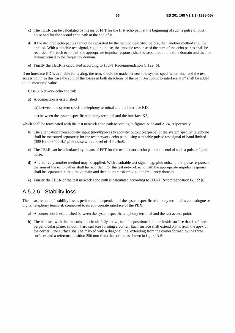
ES 201 168 V1.1.1 (1998-05)66
c) The TELR can be calculated by means of FFT for the first echo path at the beginning of such a pulse of pinknoise and for the second echo path at the end of it.
d) If the declared echo pathes cannot be separated by the method described before, then another method shall beapplied. With a suitable test signal, e.g. pink noise, the impulse response of the sum of the echo pathes shall berecorded. For each echo path the appropriate impulse response shall be separated in the time domain and then beretransformed to the frequency domain.
e) Finally the TELR is calculated according to ITU-T Recommendation G.122 [6].
If no interface KD is available for testing, the tests should be made between the system specific terminal and the testaccess point. In this case the sum of the losses in both directions of the path „test point to interface KD" shall be addedto the measured value.
Case 3: Network echo control:
a) A connection is established
aa) between the system specific telephony terminal and the interface KD,
bb) between the system specific telephony terminal and the interface K2,
which shall be terminated with the test network echo path according to figures A.23 and A.24, respectively.
b) The attenuation from acoustic input (mouthpiece) to acoustic output (earpiece) of the system specific telephoneshall be measured separately for the test network echo path, using a suitable pulsed test signal of band limited(300 Hz to 3400 Hz) pink noise with a level of -10 dBm0.
c) The TELR can be calculated by means of FFT for the test network echo path at the end of such a pulse of pinknoise.
d) Alternatively another method may be applied. With a suitable test signal, e.g. pink noise, the impulse response ofthe sum of the echo pathes shall be recorded. For the test network echo path the appropriate impulse responseshall be separated in the time domain and then be retransformed to the frequency domain.
e) Finally the TELR of the test network echo path is calculated according to ITU-T Recommendation G.122 [6].
A.5.2.6 Stability loss
The measurement of stability loss is performed independent, if the system specific telephony terminal is an analogue ordigital telephony terminal, connected to its appropriate interface of the PBX.
a) A connection is established between the system specific telephony terminal and the test access point.
b) The handset, with the transmission circuit fully active, shall be positioned on one inside surface that is of threeperpendicular plane, smooth, hard surfaces forming a corner. Each surface shall extend 0,5 m from the apex ofthe corner. One surface shall be marked with a diagonal line, extending from the corner formed by the threesurfaces and a reference position 250 mm from the corner, as shown in figure A.5:
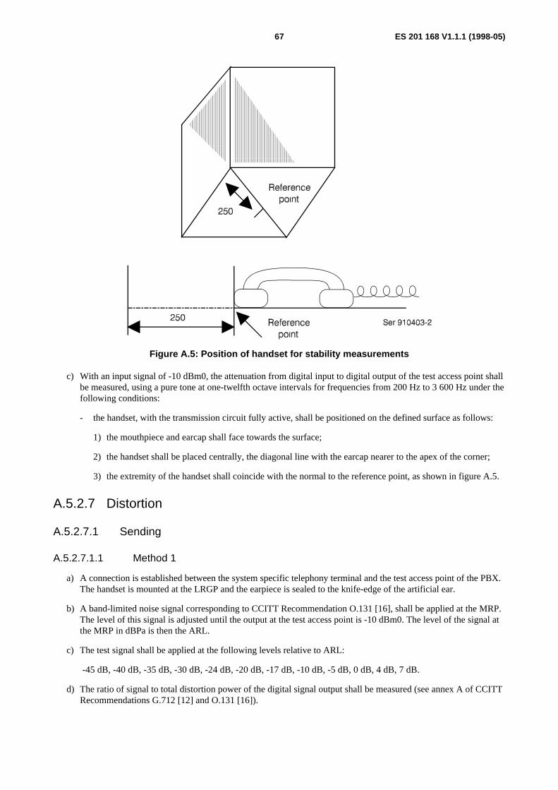
ES 201 168 V1.1.1 (1998-05)67
Figure A.5: Position of handset for stability measurements
c) With an input signal of -10 dBm0, the attenuation from digital input to digital output of the test access point shallbe measured, using a pure tone at one-twelfth octave intervals for frequencies from 200 Hz to 3 600 Hz under thefollowing conditions:
- the handset, with the transmission circuit fully active, shall be positioned on the defined surface as follows:
1) the mouthpiece and earcap shall face towards the surface;
2) the handset shall be placed centrally, the diagonal line with the earcap nearer to the apex of the corner;
3) the extremity of the handset shall coincide with the normal to the reference point, as shown in figure A.5.
A.5.2.7 Distortion
A.5.2.7.1 Sending
A.5.2.7.1.1 Method 1
a) A connection is established between the system specific telephony terminal and the test access point of the PBX.The handset is mounted at the LRGP and the earpiece is sealed to the knife-edge of the artificial ear.
b) A band-limited noise signal corresponding to CCITT Recommendation O.131 [16], shall be applied at the MRP.The level of this signal is adjusted until the output at the test access point is -10 dBm0. The level of the signal atthe MRP in dBPa is then the ARL.
c) The test signal shall be applied at the following levels relative to ARL:
-45 dB, -40 dB, -35 dB, -30 dB, -24 dB, -20 dB, -17 dB, -10 dB, -5 dB, 0 dB, 4 dB, 7 dB.
d) The ratio of signal to total distortion power of the digital signal output shall be measured (see annex A of CCITTRecommendations G.712 [12] and O.131 [16]).
ES 201 168 V1.1.1 (1998-05)68
A.5.2.7.1.2 Method 2
a) A connection is established and the handset is mounted as described in subclause A.5.2.7.1.1.
b) A sine-wave signal with a frequency in the range 1 004 Hz to 1 025 Hz shall be applied at the MRP. The level ofthis signal is adjusted until the output of the test access point is -10 dBm0. The level of the signal at the MRPin dBPa is then the ARL.
c) The test signal shall be applied at the following levels relative to ARL:
-35 dB, -30 dB, -25 dB, -20 dB, -15 dB, -10 dB, -5 dB, 0 dB, 7 dB, 10 dB.
d) The ratio of the signal to total distortion power of the digital signal output shall be measured with thepsophometric noise weighting (see CCITT Recommendations G.712 [12] and O.132 [17]).
A.5.2.7.2 Receiving
A.5.2.7.2.1 Method 1
a) A connection is established and the handset is mounted as described in subclause A.5.2.7.1.1.
b) A digitally simulated band-limited noise signal corresponding to CCITT Recommendation O.131 [16] shall beapplied at the input of the test access point at the following levels:
-55 dBm0, -50 dBm0, -45 dBm0, -40 dBm0, -34 dBm0, -30 dBm0, -27 dBm0, -20 dBm0;
-15 dBm0, -10 dBm0, -6 dBm0, -3 dBm0.
c) The ratio of signal to total distortion power shall be measured in the artificial ear (see annex A of CCITTRecommendations G.712 [12] and O.131 [16]).
A.5.2.7.2.2 Method 2
a) A connection is established and the handset is mounted as described in subclause A.5.2.7.1.1.
b) A digitally simulated sine-wave signal with a frequency in the range 1 004 Hz to 1 025 Hz shall be applied at theinput of the test access point at the following levels:
-45 dBm0, -40 dBm0, -35 dBm0, -30 dBm0, -25 dBm0, -20 dBm0, -15 dBm0, -10 dBm0, -3 dBm0, 0 dBm0.
c) The ratio of the signal-to-total distortion power shall be measured with the psophometric noise weighting in theartificial ear (see CCITT Recommendations G.712 [12] and O.132 [17]).
A.5.2.7.3 Sidetone
a) A connection is established and the handset is mounted as described in subclause A.5.2.7.1.1.
b) An instrument capable of measuring the third harmonic distortion of signals with fundamental frequencies in therange of 315 Hz to 1 kHz shall be connected to the artificial ear.
c) The digital input of the test access point shall be driven by a PCM signal, corresponding to decoder valuenumber 1.
d) A pure-tone signal of -4,7 dBPa shall be applied at the MRP at frequencies of 315 Hz, 500 Hz and 1 kHz. Foreach frequency, the third harmonic distortion shall be measured in the artificial ear.
ES 201 168 V1.1.1 (1998-05)69
A.5.2.8 Variation of gain with input level
A.5.2.8.1 Sending
a) A connection is established and the handset is mounted as described in subclause A.5.2.7.1.1.
b) A sine-wave signal with a frequency in the range 1 004 Hz to 1 025 Hz shall be applied at the MRP. The level ofthis signal is adjusted, until the output at the test access point is -10 dBm0. The level of the signal at the MRPin dBPa is then the ARL.
c) The test signal shall be applied at the following levels relative to ARL:
-45 dB, -40 dB, -35 dB, -30 dB, -25 dB, -20 dB, -15 dB, -10 dB, -5 dB, 0 dB, 4 dB, 10 dB, 13 dB.
d) The variation of gain relative to the gain for the ARL shall be measured.
NOTE: Selective measurement may be used to avoid the effects of ambient noise.
A.5.2.8.2 Receiving
a) A connection is established and the handset is mounted as described in subclause A.5.2.7.1.1.
b) A digitally simulated sine-wave signal with a frequency in the range 1 004 Hz to 1 025 Hz shall be applied at thedigital interface at the following levels:
-50 dBm0, -45 dBm0, -40 dBm0, -35 dBm0, -30 dBm0, -25 dBm0, -20 dBm0, -15 dBm0,
-10 dBm0, -6 dBm0, 0 dBm0, 3 dBm0.
c) The variation of gain relative to the gain at an input level of -10 dBm0 shall be measured in the artificial ear.
NOTE: Selective measurement may be used to avoid the effects of ambient noise.
A.5.2.9 Out-of-band signals
A.5.2.9.1 Discrimination against out-of-band input signal
a) A connection is established and the handset is mounted as described in subclause A.5.2.7.1.1.
b) Input signals at frequencies of 4,65 kHz, 5 kHz, 6 kHz, 6,5 kHz, 7 kHz and 7,5 kHz are applied at the MRP witha level of -4,7 dBPa.
c) The level of any inband image frequency at the output of the test access point shall be measured selectively.
A.5.2.9.2 Spurious out-of-band signals
a) A connection is established and the handset is mounted as described in subclause A.5.2.7.1.1.
b) Input signals at the frequencies 500 Hz, 1 000 Hz, 2 000 Hz, and 3 150 Hz are applied at the input of the testaccess point with a level of -10 dBm0.
c) The level of spurious out-of-band image signals at frequencies of up to 8 kHz shall be measured selectively in theartificial ear.
A.5.2.10 Noise
A.5.2.10.1 Sending
a) A connection between the system specific telephony terminal and the test access point is established and thehandset mounted at the LRGP with the earpiece sealed to the knife-edge of the artificial ear in a quietenvironment (ambient noise less than 30 dBA).
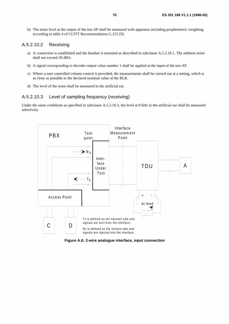
ES 201 168 V1.1.1 (1998-05)70
b) The noise level at the output of the test AP shall be measured with apparatus including psophometric weightingaccording to table 4 of CCITT Recommendation G.223 [9].
A.5.2.10.2 Receiving
a) A connection is established and the handset is mounted as described in subclause A.5.2.10.1. The ambient noiseshall not exceed 30 dBA.
b) A signal corresponding to decoder output value number 1 shall be applied at the input of the test AP.
c) Where a user controlled volume control is provided, the measurements shall be carried out at a setting, which isas close as possible to the declared nominal value of the RLR.
d) The level of the noise shall be measured in the artificial ear.
A.5.2.10.3 Level of sampling frequency (receiving)
Under the same conditions as specified in subclause A.5.2.10.2, the level at 8 kHz in the artificial ear shall be measuredselectively.
T
R X
X
Testpo in tPBX
In te r-face
U nderTest
A ccess Po in t
dc-feed
+ -
TD U A
In terfaceM easu rem en t
P o in t
C DT x is d e fin ed as th e tran sm it s id e a nds ig n a ls a re se n t from th e in te rfa ce .
R x is de fined as the receive s ide andsigna ls a re in jec ted in to the in te rface .
Figure A.6: 2-wire analogue interface, input connection
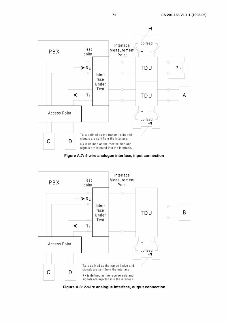
ES 201 168 V1.1.1 (1998-05)71
T
R X
X
Testpo in tPBX
In te r-face
U nderTest
A ccess Po in t
A
In terfaceM easu rem en t
P o in t
C DT x is d e fin ed as th e tran sm it s id e a nds ig n a ls a re se n t from th e in te rfa ce .
R x is defined as the rece ive s ide andsigna ls a re in jected in to the in te rface .
dc-feed
dc-feed
+ -
+ -
Z rTD U
TD U
Figure A.7: 4-wire analogue interface, input connection
T
R X
X
Testpo in tPBX
In te r-face
U nderTest
A ccess Po in t
dc-feed
+ -
TD U
In terfaceM easu rem en t
P o in t
C DT x is d e fin ed as th e tran sm it s id e a nds ig n a ls a re se n t from th e in te rfa ce .
R x is de fined as the receive s ide andsigna ls a re in jec ted in to the in te rface .
B
Figure A.8: 2-wire analogue interface, output connection
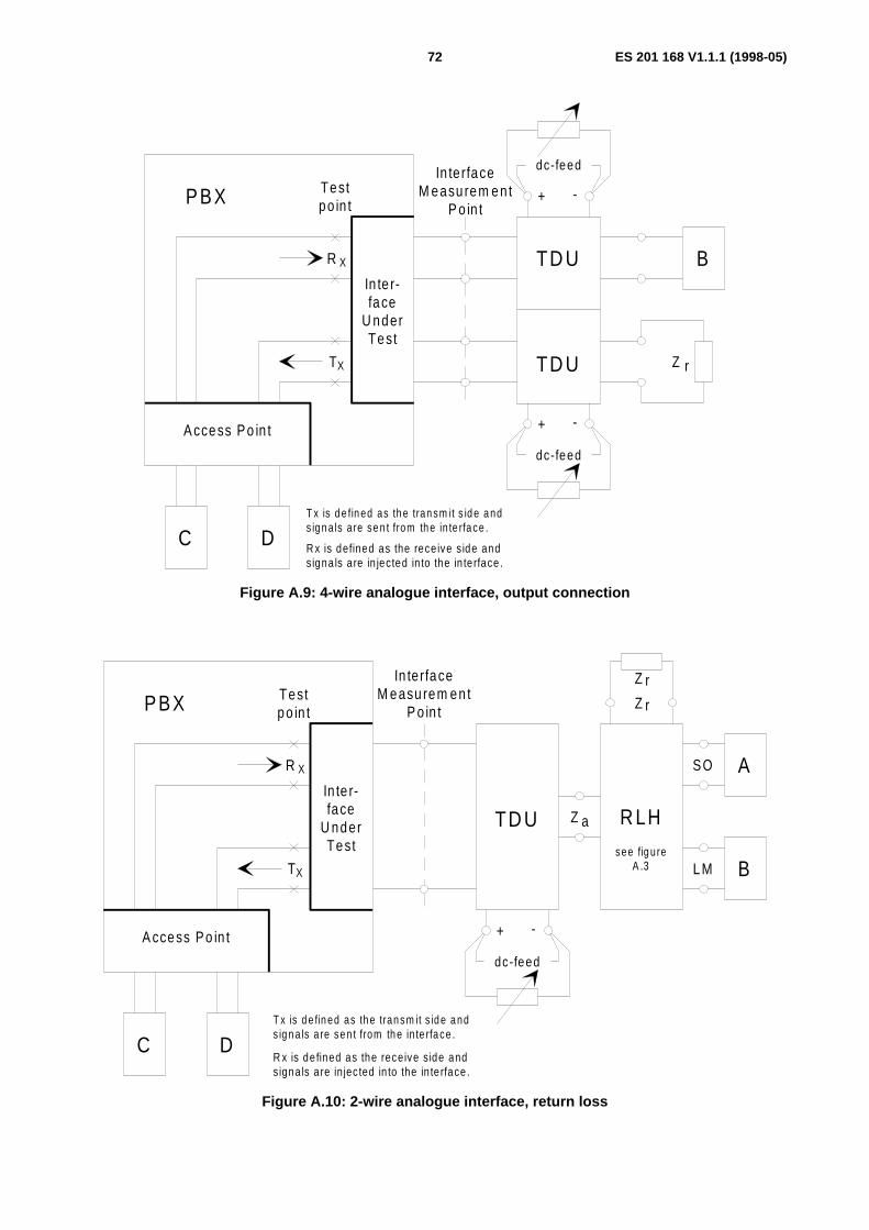
ES 201 168 V1.1.1 (1998-05)72
T
R X
X
Testpo in tPBX
In te r-face
U nderTest
A ccess Po in t
In te rfaceM easu rem en t
P o in t
C DT x is d e fin ed as th e tran sm it s id e a nds ig n a ls a re se n t from th e in te rfa ce .
R x is defined as the rece ive s ide andsigna ls a re in jected in to the in te rface .
dc-feed
dc-feed
+ -
+ -
Z r
TD U
TD U
B
Figure A.9: 4-wire analogue interface, output connection
T
R X
X
Testpo in tPBX
In te r-face
U nderTest
A ccess Po in t
dc-feed
+ -
TD U
A
In terfaceM easu rem en t
P o in t
C DT x is d e fin ed as th e tran sm it s id e a nds ig n a ls a re se n t from th e in te rfa ce .
R x is de fined as the receive s ide andsigna ls a re in jec ted in to the in te rface .
B
Z
Z r
r
SO
LM
Z a R LHsee fig u re
A .3
Figure A.10: 2-wire analogue interface, return loss

ES 201 168 V1.1.1 (1998-05)73
T
R X
X
Te stp o in tPB X
In te r-face
U nderTest
A ccess Po in t
In te rfa ceM e asure m e nt
P o in t
C DT x is d e fin ed as th e tran sm it s id e a nds ig na ls a re se n t from the in te rfa ce .
R x is defined as the rece ive s ide ands igna ls a re in jected in to the in te rface .
dc-feed
dc-feed
+ -
+ -
Z rTD U
TD U
A
LM
SO
Z
Z r
r
Z a R LHsee
figu re A .3B
Figure A.11: 4-wire analogue interface, return loss (shown only for the transmit side)
T
R X
X
Testpo in tPBX
In te r-face
U nderTest
A ccess Po in t
dc-feed
+ -
In te rfaceM easu rem en t
P o in t
TD U
C D
Z BN
Z B N = B a lance test ne tw o rk
Figure A.12: Terminal Balance Return Loss, stability
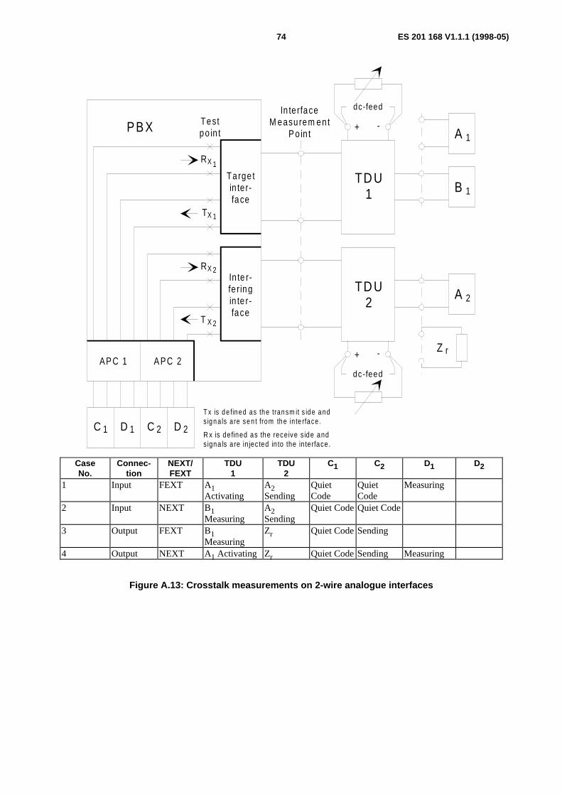
ES 201 168 V1.1.1 (1998-05)74
dc-feed
dc-feed
+ -
+ -
PB X Testpo in t
RX
TX
1
1
RX 2
T X 2
Ta rge tin te r-face
In te r-fe ringin te r-face
AP C 1 A PC 2
C 1 D C D1 2 2
TD U1
TD U2
In terfaceM easu rem en t
P o in t
B 1
A 2
T x is d e fin ed as th e tran sm it s id e a nds ig n a ls a re se n t from th e in te rfa ce .
R x is de fined as the receive s ide andsigna ls a re in jec ted in to the in te rface .
A 1
Z r
CaseNo.
Connec-tion
NEXT/FEXT
TDU1
TDU2
C1 C2 D1 D2
1 Input FEXT A1Activating
A2Sending
QuietCode
QuietCode
Measuring
2 Input NEXT B1Measuring
A2Sending
Quiet Code Quiet Code
3 Output FEXT B1Measuring
Zr Quiet Code Sending
4 Output NEXT A1 Activating Zr Quiet Code Sending Measuring
Figure A.13: Crosstalk measurements on 2-wire analogue interfaces
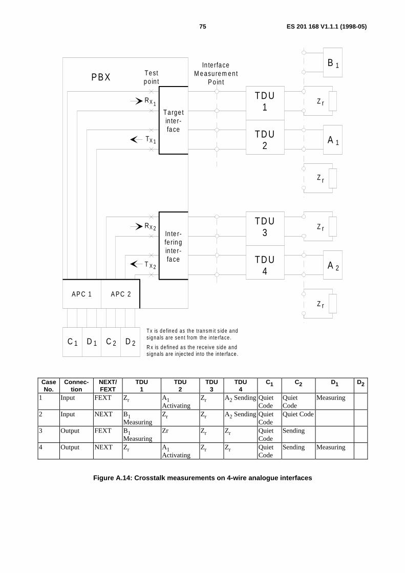
ES 201 168 V1.1.1 (1998-05)75
PB X Testpo in t
RX
TX
1
1
RX 2
T X 2
Ta rge tin te r-face
In te r-fe ringin te r-face
AP C 1 A PC 2
C 1 D C D1 2 2
In terfaceM easu rem en t
P o in t
A 1
A 2
T x is d e fin ed as th e tran sm it s id e a nds ig n a ls a re se n t from th e in te rfa ce .
R x is de fined as the receive s ide andsigna ls a re in jec ted in to the in te rface .
Z r
Z rTD U
1
TD U2
TD U3
TD U4
Z r
Z r
B 1
CaseNo.
Connec-tion
NEXT/FEXT
TDU1
TDU2
TDU3
TDU4
C1 C2 D1 D2
1 Input FEXT Zr A1Activating
Zr A2 Sending QuietCode
QuietCode
Measuring
2 Input NEXT B1Measuring
Zr Zr A2 Sending QuietCode
Quiet Code
3 Output FEXT B1Measuring
Zr Zr Zr QuietCode
Sending
4 Output NEXT Zr A1Activating
Zr Zr QuietCode
Sending Measuring
Figure A.14: Crosstalk measurements on 4-wire analogue interfaces

ES 201 168 V1.1.1 (1998-05)76
PB X Testpo in t
RX
TX
1
1
RX 2
T X 2
In te r-fe ring /ta rge tin te r-face
2 -w ire
Ta rge t/in te r-fe ringin te r-face
4 -w ire
AP C 1 A PC 2
C 1 D C D1 2 2
In terfaceM easu rem en t
P o in t
B 1
A 1
T x is d e fin ed as th e tran sm it s id e a nds ig n a ls a re se n t from th e in te rfa ce .
R x is de fined as the receive s ide andsigna ls a re in jec ted in to the in te rface .
Z r
TD U1
TD U2
TD U3
Z r
Z r
A 1
B 1
A 2
A 2
dc-feed
+ -
Figure A.15 (continued): Crosstalk measurements between 4-wire and 2-wire analogue interfaces
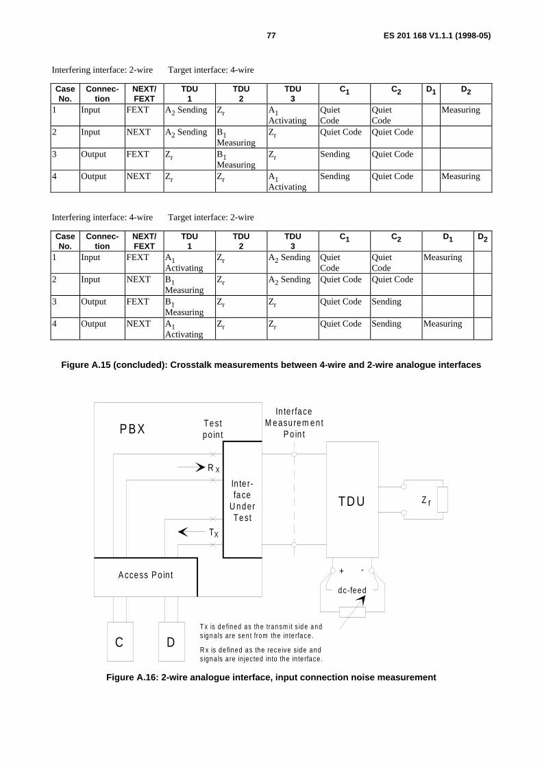
ES 201 168 V1.1.1 (1998-05)77
Interfering interface: 2-wire Target interface: 4-wire
CaseNo.
Connec-tion
NEXT/FEXT
TDU1
TDU2
TDU3
C1 C2 D1 D2
1 Input FEXT A2 Sending Zr A1Activating
QuietCode
QuietCode
Measuring
2 Input NEXT A2 Sending B1Measuring
Zr Quiet Code Quiet Code
3 Output FEXT Zr B1Measuring
Zr Sending Quiet Code
4 Output NEXT Zr Zr A1Activating
Sending Quiet Code Measuring
Interfering interface: 4-wire Target interface: 2-wire
CaseNo.
Connec-tion
NEXT/FEXT
TDU1
TDU2
TDU3
C1 C2 D1 D2
1 Input FEXT A1Activating
Zr A2 Sending QuietCode
QuietCode
Measuring
2 Input NEXT B1Measuring
Zr A2 Sending Quiet Code Quiet Code
3 Output FEXT B1Measuring
Zr Zr Quiet Code Sending
4 Output NEXT A1Activating
Zr Zr Quiet Code Sending Measuring
Figure A.15 (concluded): Crosstalk measurements between 4-wire and 2-wire analogue interfaces
T
R X
X
Testpo in tPBX
In te r-face
U nderTest
A ccess Po in t
dc-feed
+ -
TD U
In terfaceM easu rem en t
P o in t
C DT x is d e fin ed as th e tran sm it s id e a nds ig n a ls a re se n t from th e in te rfa ce .
R x is de fined as the receive s ide andsigna ls a re in jec ted in to the in te rface .
Z r
Figure A.16: 2-wire analogue interface, input connection noise measurement
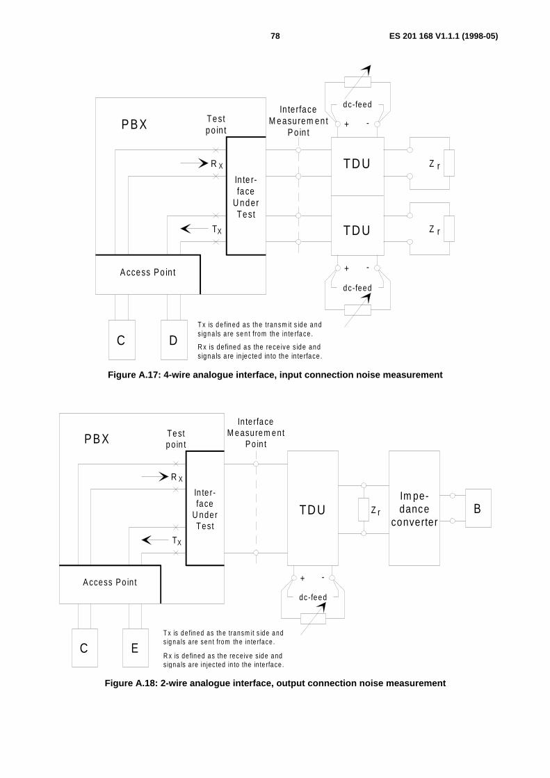
ES 201 168 V1.1.1 (1998-05)78
T
R X
X
Testpo in tPBX
In te r-face
U nderTest
A ccess Po in t
In te rfaceM easu rem en t
P o in t
C DT x is d e fin ed as th e tran sm it s id e a nds ig n a ls a re se n t from th e in te rfa ce .
R x is defined as the rece ive s ide andsigna ls a re in jected in to the in te rface .
dc-feed
dc-feed
+ -
+ -
Z r
TD U
TD U
Z r
Figure A.17: 4-wire analogue interface, input connection noise measurement
T
R X
X
Te stp o in tPB X
In te r-face
U nderTest
A ccess Po in t
dc-feed
+ -
TD U
Inte rfa ceM e asure m e nt
P o in t
C ET x is d e fin ed as th e transm it s id e a nds ig n a ls a re se n t from th e in te rface .
R x is de fined as the receive s ide ands igna ls a re injec ted in to the in te rface .
BZ r
Im pe-dance
converter
Figure A.18: 2-wire analogue interface, output connection noise measurement
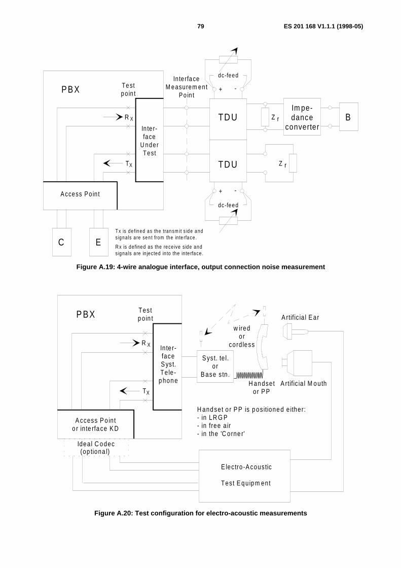
ES 201 168 V1.1.1 (1998-05)79
T
R X
X
Te stp o in tPB X
In te r-face
U nderTest
A ccess Po in t
In te rfa ceM e asure m e nt
P o in t
C ET x is d e fin ed as th e tran sm it s id e a nds ig na ls a re se n t from the in te rfa ce .
R x is defined as the rece ive s ide ands igna ls a re in jected in to the in te rface .
dc-feed
dc-feed
+ -
+ -
Z r
TD U
TD U
BIm pe-dance
converterZ r
Figure A.19: 4-wire analogue interface, output connection noise measurement
T
R X
X
Testp o in tP BX
Inter-faceS yst.Te le -
p hon e
A ccess P o in to r in te rfa ce K D
S yst. te l.o r
B ase s tn .
Idea l C o dec
E lec tro -A coustic
Tes t E q u ip m ent
A rtif ic ia l E ar
A rtif ic ia l M o uthH an dsetor P P
(op tiona l)
H and set o r P P is p os itione d e ither:- in LR G P - in free a ir- in the 'C orne r'
w iredor
cord less
Figure A.20: Test configuration for electro-acoustic measurements
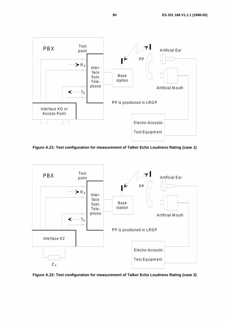
ES 201 168 V1.1.1 (1998-05)80
T
R X
X
Testp o in tP B X
Inte r-faceS yst.Te le -
p hone
In terface K D o rA ccess P o in t
B ases ta tion
E lec tro -A coustic
Tes t E q u ip m ent
A rtif ic ia l E ar
A rtif ic ia l M outh
P P
P P is p os itioned in LR G P
Figure A.21: Test configuration for measurement of Talker Echo Loudness Rating (case 1)
T
R X
X
Testp o in tP BX
Inter-faceS yst.Te le -
p hon e
In terface K 2
B asesta tion
E lec tro -A coustic
Tes t E q u ip m ent
A rtif ic ia l E ar
A rtif ic ia l M ou th
P P
P P is po s itio ned in L R G P
Z r
Figure A.22: Test configuration for measurement of Talker Echo Loudness Rating (case 2)
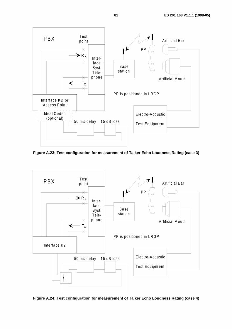
ES 201 168 V1.1.1 (1998-05)81
T
R X
X
Testp o in tP BX
Inter-faceS yst.Te le -
p hon e
In terface K D orA ccess P o in t
B ases ta tion
E lec tro -A coustic
Tes t E q u ip m ent
A rtif ic ia l E ar
A rtif ic ia l M ou th
P P
P P is po s itio ned in L R G P
Idea l C o dec(op tion a l)
50 m s de la y 1 5 dB loss
Figure A.23: Test configuration for measurement of Talker Echo Loudness Rating (case 3)
T
R X
X
Testp o in tP BX
Inter-faceS yst.Te le -
p hon e
In terfa ce K 2
B asesta tion
E lec tro -A coustic
Tes t E q u ip m ent
A rtif ic ia l E ar
A rtif ic ia l M ou th
P P
P P is po s itio ned in L R G P
50 m s de la y 1 5 dB loss
Figure A.24: Test configuration for measurement of Talker Echo Loudness Rating (case 4)
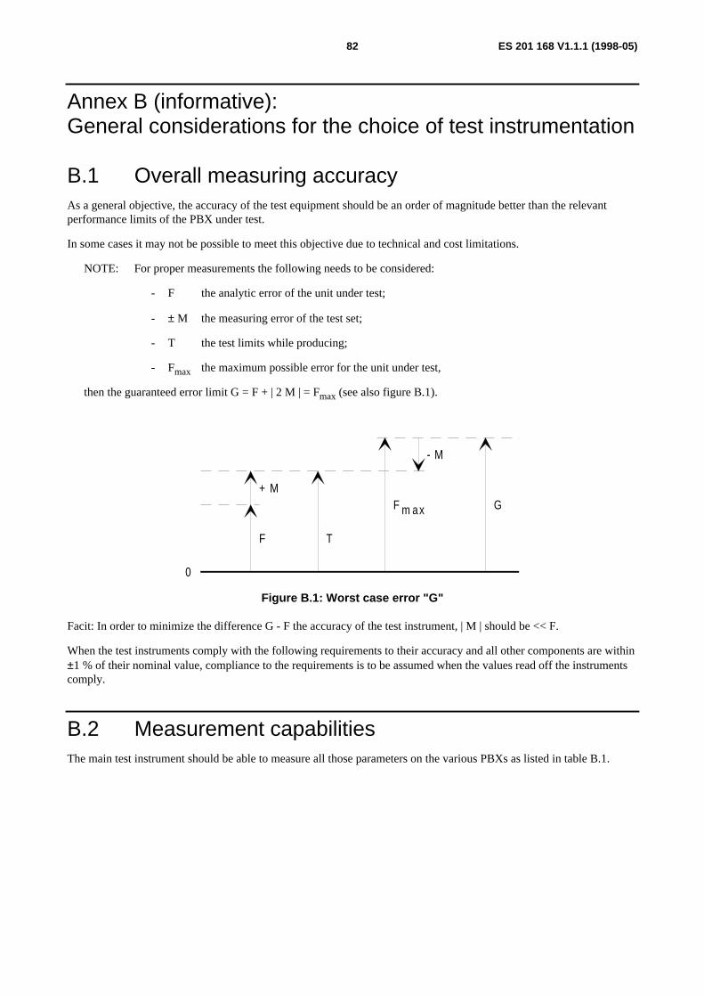
ES 201 168 V1.1.1 (1998-05)82
Annex B (informative):General considerations for the choice of test instrumentation
B.1 Overall measuring accuracyAs a general objective, the accuracy of the test equipment should be an order of magnitude better than the relevantperformance limits of the PBX under test.
In some cases it may not be possible to meet this objective due to technical and cost limitations.
NOTE: For proper measurements the following needs to be considered:
- F the analytic error of the unit under test;
- ± M the measuring error of the test set;
- T the test limits while producing;
- Fmax the maximum possible error for the unit under test,
then the guaranteed error limit G = F + | 2 M | = Fmax (see also figure B.1).
F m ax G+ M
- M
F T
0
Figure B.1: Worst case error "G"
Facit: In order to minimize the difference G - F the accuracy of the test instrument, | M | should be << F.
When the test instruments comply with the following requirements to their accuracy and all other components are within±1 % of their nominal value, compliance to the requirements is to be assumed when the values read off the instrumentscomply.
B.2 Measurement capabilitiesThe main test instrument should be able to measure all those parameters on the various PBXs as listed in table B.1.

ES 201 168 V1.1.1 (1998-05)83
Table B.1: Measurement capabilities
Parameter Measuring Configuration according to ITU-T/CCITT Recommendation
Measurement Facility
Transmission loss A, B, C, D O.133 [18] EEcho and stability C, DImpedance(return loss)
A, B O.133 [18] E
Unbalance A, B, C O.9 [14], G.117, O.133 [18] ELoss distortion with frequency A, B, C, D EAbsolute group delay A, B, C, D EGroup delay distortion A, B OWeighted noise A, B, C, D O.133 [18] EDiscrimination againstout of band signals
A (see note), B, D O
Spuriousout of band signals
A, B (see note), C O
Single frequency noise B (see note) OTotal distortion inclusive quantizingdistortion
A, B, C, D O.132 [17], O.133 [18] E
Variation of gainwith input level
A, B, C, D O.133 [18] E
Crosstalk A, B / C, B / A, D ENOTE: A = Analogue signal generatorNOTE: B = Analogue signal analyserNOTE: C = Digital signal generatorNOTE: D = Digital signal analyserNOTE: E = EssentialNOTE: O = OptionalNOTE: frequency range 4,6 kHz to 72 kHz
B.3 Instrument requirementsThis paragraph describes the minimum requirements to be met by the four functional units of the instrumentation.Measuring accuracy is given in subclause B.4.
Test instruments equipped with standardized digital interfaces and their interworking with the AP, see subclause A.2.2.
Analogue test instrumentation impedances needs to be in accordance with subclause A.1.4.
The output- and input-impedances, of the analogue test instrumentation is to be balanced and earthfree. It isrecommended, that the following impedance values are provided:
- Output impedance: 600 Ω, 0 Ω, complex (optional)
- Input impedance : 600 Ω, > 30 k Ω, complex (optional)
NOTE: For different complex impedances the use of an external impedance converter is recommended.
The requirements for return loss against 600 Ω (or complex impedance) and Longitudinal Conversion Loss (LCL) forinput and output impedances are:
600 Ω: 200 Hz to 4 000 Hz > 46 dB
Complex: 200 Hz to 500 Hz > 36 dB
500 Hz to 2 500 Hz > 40 dB
2500 Hz to 4 000 Hz > 36 dB
For unbalance measurements the LCL of the test instrument itself should be ≥ 66 dB in the range from 15 Hz to 4 kHz.

ES 201 168 V1.1.1 (1998-05)84
B.4 Measuring accuracyConsidering the measuring accuracy the following facts shall be taken into account.
Even ideal coders/decoders exhibit intrinsic limitations due to the PCM-process which cannot be avoided (see annex Aof ITU-T Recommendation O.133 [18]).
The measuring instrumentation described here has no better characteristics and limitations as an ideal coder/decoder.Therefore, the difference between an ideal coder/decoder and the measuring instrument are defined as measuring errorsin the present document.
The total measuring error limits for the test instrumentation can be mainly derived by the sum of errors according to thedifferent configurations of the functional units.
In the following tables the error limits are listed, depending on the type of parameter to be measured and the type ofconnection.
Table B.2: Error limits for transmission loss
Error limits [dB]Parameter Output/input connection Half connection
IMP ←→ AP IMP APRelative levels(see note)
(Transmission Loss)± 0,08
NOTE: Measured at a frequency of 1 020 + 2 / -7 Hz and at a level of 0 dBm0.
Table B.3: Error limits for echo and stability
Error limits [dB]Parameter Output/input connection Half connection
IMP ←→ AP IMP APTBRL, echo, stability ± 0,1
Table B.4: Error limits for impedance measurements (return loss)
Error limits [dB]Parameter Indicated result Output/input connection Half connection
IMP ←→ AP IMP APReturn 0 dB to 30 dB ±1
loss 30 dB to 40 dB ±2
Table B.5: Error limits for unbalance measurements
Error limits [dB]Parameter Indicated result Output/input connection Half connection
IMP ←→ AP IMP APUnbalance 5 dB to 40 dB ± 1,5 about earth 40 dB to 56 dB ± 2,5
Measured at a level of ≥ - 10 dBm0.

ES 201 168 V1.1.1 (1998-05)85
Table B.6: Error limits for loss distortion with frequency
Error limits [dB]Parameter Frequency range Output/input connection Half connection
IMP ←→ AP IMP APLoss distortion 200 Hz to 300 Hz ± 0,08
with 300 Hz to 3 400 Hz ± 0,05 frequency 3 400 Hz to 3 600 Hz ± 0,08
Measured at a level of 0 dBm0 or - 10 dBm0 and referred to a frequency of 1 020 +2/-7 Hz.
Table B.7: Error limits for absolute group delay
Error limits [µs]Parameter Receive level Output/input connection Half connection
IMP ←→ IMP IMP APAbsolute
group delay0 dBm0 to -10 dBm0 ± 15 (see note)
NOTE: Due to total distortion including quantizing distortion of the PBX, measurement is proposed in the range500 Hz to 2 800 Hz.
Table B.8: Error limits for group delay distortion
Error limits [µs]Parameter Frequency range Output/input connection Half connection
IMP ←→ AP IMP APGroup delay
distortion0 dBm0 to -10 dBm0 ± 30 (see note)
NOTE: Due to total distortion including quantizing distortion of the PBX, measurement is proposed in the range500 Hz to 2 800 Hz.
Table B.9: Error limits for weighted noise
Error limits [dB]Parameter Indicated result Output/input connection Half connection
IMP ←→ AP IMP AP- 80 dBm0p to
- 75 dBm0p± 2,5
Weighted noise - 75 dBm0p to- 70 dBm0p
± 1,5
- 70 dBm0p to- 20 dBm0p
± 1
Measurement error includes tolerances of the weighting filter given in ITU-T Recommendation O.41 [15]
Table B.10: Error limits for discrimination against out-of-band signals
Error limits [dB]Parameter Output/input connection Half connection
IMP → AP IMP APDiscrimination against out-of-band
input signals± 0,5
The test signal is a sine-wave above 4,6 kHz with a level of -25 dBm0.

ES 201 168 V1.1.1 (1998-05)86
Table B.11: Error limits for spurious out-of band signals at the PBX output
Error limits [dB]Parameter Output/input connection Half connection
IMP ← AP IMP APSpurious out-of-band signals
at the PBX output± 0,5
The test signal is a sine-wave in the range 300 Hz to 3 400 Hz with 0 dBm0.The received inband-signal is to be measured selectively.
Table B.12: Error limits for single frequency noise at the PBX output
Error limits [dB]Parameter Output/input connection Half connection
IMP IMP APSingle frequency noise ± 1
The received output signal has to be measured selectively.
Table B.13: Error limits for total distortion including quantizing distortion
Error limits [dB]Parameter Indicated result Output/input connection Half connection
IMP ←→ AP IMP APTotal 0 dB to 40 dB ± 0,5
distortion 40 dB to 43 dB ± 1 Measured with sinusoidal test signal of approximately 1 020 Hz. The absolute distortion signal is not less than-72 dBm0.
Table B.14: Error limits for variation of gain with input level
Error limits [µs]Parameter Level range Output/input connection Half connection
IMP←→ AP IMP AP
Variation+3 dBm0 to-40 dBm0
± 0,1
of gain withinput level
-40 dBm0 to-50 dBm0
± 0,15
-50 dBm0 to-55 dBm0
± 0,20
Error referred to measurement of -10 dBm0. The test signal is sinusoidal at a frequency of 1 020 +2/-7 Hz and a levelof -10 dBm0.
Table B.15: Error limits for crosstalk measurement
Error limits [dB]Parameter Test signal Output/input connection Half connection
IMP ←→ AP IMP APCross- Sinus 1 020 Hz (see note) ± 1 ± 1 ± 1
talk Convent. teleph. ± 1,5 NOTE: Measurement to be performed while injecting an auxiliary signal (defined in subclause 3.2.4 of ITU-T
Recommendation O.133 [18]) in the disturbed PBX. Error includes the effect of finite rejection of theauxiliary signal by the measurement filter and of quantizing distortion in the measuring bandwidth.
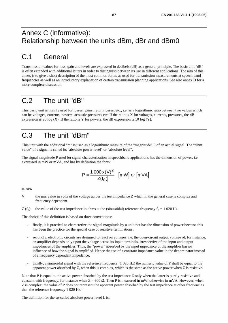
ES 201 168 V1.1.1 (1998-05)87
Annex C (informative):Relationship between the units dBm, dBr and dBm0
C.1 GeneralTransmission values for loss, gain and levels are expressed in decibels (dB) as a general principle. The basic unit "dB"is often extended with additional letters in order to distinguish between its use in different applications. The aim of thisannex is to give a short description of the most common forms as used for transmission measurements at speech bandfrequencies as well as an introductory explanation of certain transmission planning applications. See also annex D for amore complete discussion.
C.2 The unit "dB"This basic unit is mainly used for losses, gains, return losses, etc., i.e. as a logarithmic ratio between two values whichcan be voltages, currents, powers, acoustic pressures etc. If the ratio is X for voltages, currents, pressures, the dBexpression is 20 log (X). If the ratio is Y for powers, the dB expression is 10 log (Y).
C.3 The unit "dBm"This unit with the additional "m" is used as a logarithmic measure of the "magnitude" P of an actual signal. The "dBmvalue" of a signal is called its "absolute power level" or "absolute level".
The signal magnitude P used for signal characterization in speechband applications has the dimension of power, i.e.expressed in mW or mVA, and has by definition the form:
[ ] [ ]Px V
Z fmW= 1 000 2
0
or mVA
( )( )
where:
V: the rms value in volts of the voltage across the test impedance Z which in the general case is complex andfrequency dependent.
Z (f0): the value of the test impedance in ohms at the (sinusoidal) reference frequency f0 = 1 020 Hz.
The choice of this definition is based on three conventions:
- firstly, it is practical to characterize the signal magnitude by a unit that has the dimension of power because thishas been the practice for the special case of resistive terminations;
- secondly, electronic circuits are designed to react on voltages, i.e. the open-circuit output voltage of, for instance,an amplifier depends only upon the voltage across its input terminals, irrespective of the input and outputimpedances of the amplifier. Thus, the "power" absorbed by the input impedance of the amplifier has noinfluence of how the signal is amplified. Hence the use of a constant impedance value in the denominator insteadof a frequency dependant impedance;
- thirdly, a sinusoidal signal with the reference frequency (1 020 Hz) the numeric value of P shall be equal to theapparent power absorbed by Z, when this is complex, which is the same as the active power when Z is resistive.
Note that P is equal to the active power absorbed by the test impedance Z only when the latter is purely resistive andconstant with frequency, for instance when Z = 600 Ω. Then P is measured in mW, otherwise in mVA. However, whenZ is complex, the value of P does not represent the apparent power absorbed by the test impedance at other frequenciesthan the reference frequency 1 020 Hz.
The definition for the so-called absolute power level L is:
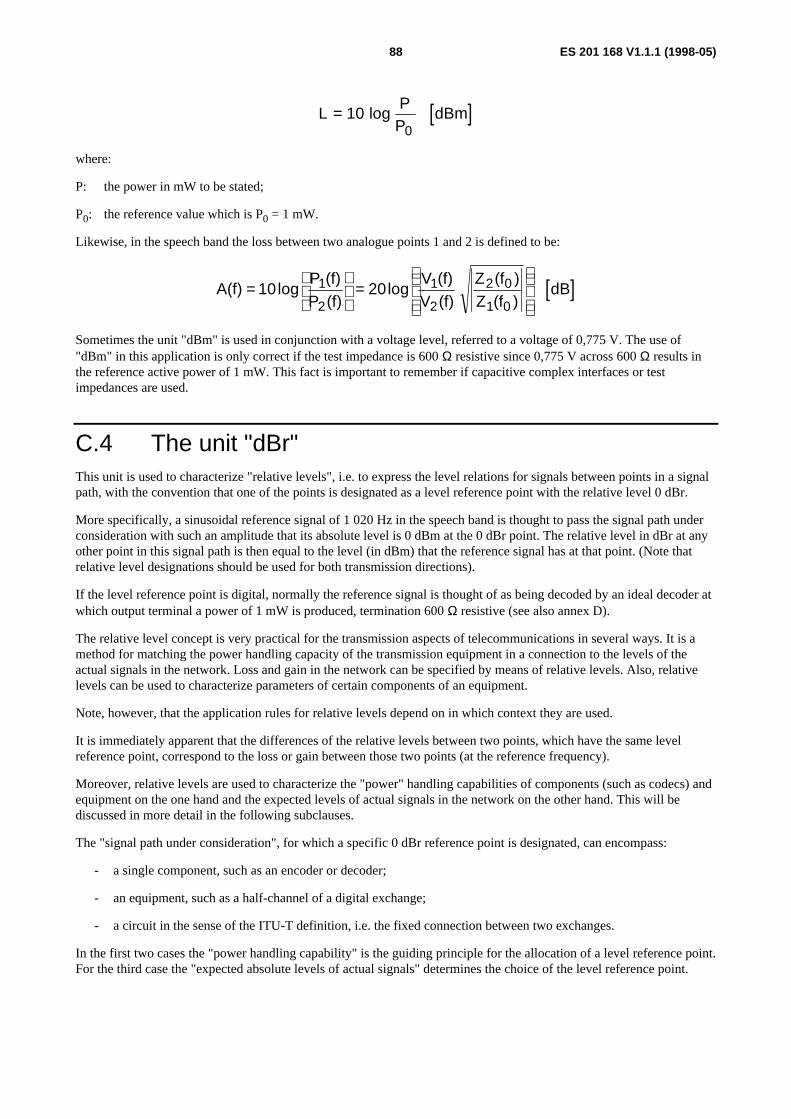
ES 201 168 V1.1.1 (1998-05)88
[ ]LP
PdBm= 10
0log
where:
P: the power in mW to be stated;
P0: the reference value which is P0 = 1 mW.
Likewise, in the speech band the loss between two analogue points 1 and 2 is defined to be:
[ ]A(f) 10logP (f)P (f)
20logV (f)V (f)
Z (f )Z (f )
1
2
1
2
2 0
1 0=
=
dB
Sometimes the unit "dBm" is used in conjunction with a voltage level, referred to a voltage of 0,775 V. The use of"dBm" in this application is only correct if the test impedance is 600 Ω resistive since 0,775 V across 600 Ω results inthe reference active power of 1 mW. This fact is important to remember if capacitive complex interfaces or testimpedances are used.
C.4 The unit "dBr"This unit is used to characterize "relative levels", i.e. to express the level relations for signals between points in a signalpath, with the convention that one of the points is designated as a level reference point with the relative level 0 dBr.
More specifically, a sinusoidal reference signal of 1 020 Hz in the speech band is thought to pass the signal path underconsideration with such an amplitude that its absolute level is 0 dBm at the 0 dBr point. The relative level in dBr at anyother point in this signal path is then equal to the level (in dBm) that the reference signal has at that point. (Note thatrelative level designations should be used for both transmission directions).
If the level reference point is digital, normally the reference signal is thought of as being decoded by an ideal decoder atwhich output terminal a power of 1 mW is produced, termination 600 Ω resistive (see also annex D).
The relative level concept is very practical for the transmission aspects of telecommunications in several ways. It is amethod for matching the power handling capacity of the transmission equipment in a connection to the levels of theactual signals in the network. Loss and gain in the network can be specified by means of relative levels. Also, relativelevels can be used to characterize parameters of certain components of an equipment.
Note, however, that the application rules for relative levels depend on in which context they are used.
It is immediately apparent that the differences of the relative levels between two points, which have the same levelreference point, correspond to the loss or gain between those two points (at the reference frequency).
Moreover, relative levels are used to characterize the "power" handling capabilities of components (such as codecs) andequipment on the one hand and the expected levels of actual signals in the network on the other hand. This will bediscussed in more detail in the following subclauses.
The "signal path under consideration", for which a specific 0 dBr reference point is designated, can encompass:
- a single component, such as an encoder or decoder;
- an equipment, such as a half-channel of a digital exchange;
- a circuit in the sense of the ITU-T definition, i.e. the fixed connection between two exchanges.
In the first two cases the "power handling capability" is the guiding principle for the allocation of a level reference point.For the third case the "expected absolute levels of actual signals" determines the choice of the level reference point.

ES 201 168 V1.1.1 (1998-05)89
The aim is of course to match the component performance to the requirement for the equipment performance which inturn should be matched to the actual range of signal levels. However, it is not always possible to achieve this exactly.For this and other reasons, the allocation of the 0 dBr reference point in the signal path may be chosen differently in thethree cases above, i.e. when the component is considered alone, when it is considered as part of the equipment, andwhen the equipment is a part of the circuit. This means that the relative level designation for a certain point sometimesmay differ in these three cases, a fact which should be remembered when discussing relative levels.
NOTE: It would be easy to surmise that there is only one level reference point in the network to which all relativelevels are referred. However, this is not the case. As a matter of fact, in a complete connection, severaldifferent level reference points can be designated. These may also be different from those chosen whenthe parts of the transmission links are considered separately in the context of parameters for equipment orcomponents. Thus, when stating the relative level at a point one should make it quite clear in whichcontext this relative level applies.
A more detailed discussion of the various applications of relative levels is given in annex D (see also ITU-TRecommendations G.100 and G.101 [3]).
Note that a so-called "level jump" may be introduced at the interconnection point between two (ITU-T) circuits. Thus,the loss or gain between two points belonging to two different circuits is not always equal to the difference in their(circuit) relative levels. Such an example is the case of the input and output relative levels of a digital exchange havingno digital loss or gain pads. When the exchange is considered as an equipment, the difference between the (equipment)input and output relative levels gives the loss through the exchange because the two half-channels have the same levelreference point. When the exchange is considered as a part of a connection, the two half-channels belong to twodifferent (ITU-T) circuits which are interconnected "in the middle of" the switching matrix. The (circuit) input andoutput relative levels for the exchange, which are stated in the transmission plan for the connection, can differ from thespecified (equipment) relative levels. This is because the (circuit) relative levels refer to two separate level referencepoints, each determined by estimation of expected signal levels in the two circuits (in general, however, the differencesare not very large).
For the purpose of equipment parameter specification and transmission measurement, which is of interest here, the"power handling capability" is the governing factor for the choice of the 0 dBr level reference point. In this context, thedigital 64 kbit/s PCM bit-stream is considered as having a relative level of 0 dBr, provided that there are no digital lossor gain pads in its path. Ideal encoders and decoders connected to the bit-stream are defined as having 0 dBr relativelevels at their analogue ports when their clipping level for a sinusoidal signal lies at +3,14 dBm (A-law). The relativelevel for real encoders and decoders connected to the bit-stream is determined by means of the actual clipping levels inrelation to the clipping levels of the ideal codecs.
When a digital loss or gain pad is included in the digital bit-stream, one has to make a choice of which side of the padthe bit-stream is to be assigned to 0 dBr. In the context of equipment specification and transmission measurement, it hasbeen found most practical to apply a convention that a digital bit-stream never should be assigned a higher relative levelthan 0 dBr. This means that:
- a digital pad with L dB loss has the relative levels of 0 dBr at the input and -L dBr at the output;
- a digital pad with G dB gain has the relative levels of -G dBr at the input and 0 dBr at the output.
Note that in the context of transmission planning, a digital bit-stream sometimes may be assigned a relative level whichis different from 0 dBr even if there is no digital pad in the digital path (see clause D.3).
Subclause D.4.3 lists another couple of possible choices of the 0 dBr point in digital exchanges.
C.5 The unit "dBm0"When using an additional "m" and "0" (zero) with the basic "dB", the level under consideration is expressed as theabsolute level (dBm) of the same signal that would be measured at the relevant 0 dBr level reference point.
This term is used in conjunction with transmission measurements to specify test levels and test results; the term alsofacilitates the comparison of the power levels of different signals by referring them to a common reference point, i.e. the0 dBr reference point. Networks are often designed to carry different types of signals (speech, modem, fax, etc.) atdifferent levels, expressed in dBm0.

ES 201 168 V1.1.1 (1998-05)90
C.6 The letter "p" in "dBmp" and "dBm0p"The additional small letter "p" is derived from the French word "ponderé" for "weighted" and means that the consideredvalue is a noise level, measured by a psophometer with a special noise weighting filterincluded as described in ITU-TRecommendations O.41 [15] and O.41 [15].
C.7 The relationship between dBm, dBr and dBm0The relationship between relative levels at interfaces, which have the same level reference point, and the resultingtransmission loss or gain "L", is given by the formula:
L = Li - Lo
where Li and Lo are the relative input and output levels at the interfaces (see also subclause 3.1.4.1).
The relation between the terms dBm, dBr and dBm0 can be expressed by the following formula:
dBm = dBm0 + dBr (general)
dBmp = dBm0p + dBr (for weighted noise)
or
dBm0 = dBm - dBr (general)
dBm0p = dBmp - dBr (for weighted noise)
EXAMPLE 1: The test level for an interface with an input relative level of Li = -2 dBr, is required to be-10 dBm0. To what absolute power level in dBm the signal generator should be adjusted?
dBm = dBm0 + dBr
= -10 + ( -2) = -12 dBm.
EXAMPLE 2: The dial tone level at an interface with an output relative level of Lo = -7 dBr was measured with-19 dBm. Does this value meet the requirement given with ≤ -15 dBm0 for this type of interface?
dBm0 = dBm - dBr
= -19 - ( -7) = -12 dBm0.
The result shows, that the dial tone level is outside the limit.
NOTE: Some modern test instruments are providing as well an automatic adjustment of the correct absolute testlevel, as the necessary correction of received levels and displaying the results in "dBm0". In those casesthe above given calculation can be avoided, however an additional adjustment (beside the test level itself)is required, to adapt the test instrument to the relative input- and output levels of the test object.
C.8 Correction factorsDepending on the type of test instruments, auxiliary equipment and test objects, sometimes correction factors need to beused, to either adjust the correct test signal level, or to obtain the correct test result. This mainly occurs in conjunctionwith capacitive complex impedances.
In practice, test instruments may be used with input/output impedances only 600 Ω resistive and consequently sendlevels or displayed results referred to 1 mW. To provide the correct termination of test objects with compleximpedances, auxiliary equipments called "impedance converter" are used. The principle of such an impedance converteris shown in figure C.1 in the application for sending and in figure C.2 for receiving.

ES 201 168 V1.1.1 (1998-05)91
~ Z I Z in S
Z o ut / 2
Z out / 2
Z P A B X
P A B Xun der tes t
In terfaceM ea su re m ent
P oin t
Im pe danceconve rte r
S ig na lg en erator
S end leve lL [d B m ]S
Test leve lL [d B m 0 ]T
R elativ e in pu tleve l L [dB r]
i
Figure C.1: Impedance converter in the sending path
Z I
Z out / 2
Z out / 2
S Z inZ P A B X
Inte rfa ceM e asurem en t
P oint
P A B Xun der tes t
Im pe dancecon verter
S ig na lreceiv er
D isp layedre la tive le ve l
L [dB m ]R
Test leve lL [dB m 0 ]T
R ela tiv e o u tp utlev e l L [dB r]o
~
Figure C.2: Impedance converter in the receive path
An advantageous design is, to obtain a power transfer ratio of 1 at the reference frequency 1 020 Hz, if terminated withthe respective nominal impedances at input and output. In this case the voltage gain "s" of the inserted amplifier is:
[ ]sZZ
dBout
in= +6 10log
This formula is valid for send and receive part of an impedance converter. It should be noted, that if Zout or Zin is acomplex impedance, the modula at the reference frequency 1 020 Hz has to be used.
For impedance converters in the application with different complex impedances the gain "s" is normally only adjusted to6 dB (power transfer ratio = 1 only, if Zin = Zout) and correction values are used as follows:
Sending a test signal
In this application (see figure C.1) Zin is exactly matched to the impedance Zi of the signal generator (e.g. 600 Ω) andZout is the nominal value of the interface impedance ZPBX of the PBX under test.
To obtain the required test level LT in dBm0 at the IMP, the necessary send level LS in dBm of the signal generator canbe calculated as follows:
L dBm L dBm L dBrZZS T iout
in= + +0 10log
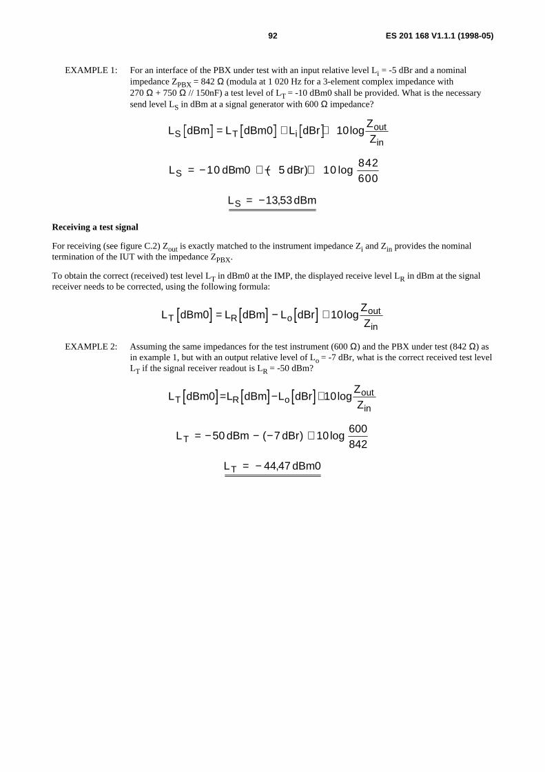
ES 201 168 V1.1.1 (1998-05)92
EXAMPLE 1: For an interface of the PBX under test with an input relative level Li = -5 dBr and a nominalimpedance ZPBX = 842 Ω (modula at 1 020 Hz for a 3-element complex impedance with270 Ω + 750 Ω // 150nF) a test level of LT = -10 dBm0 shall be provided. What is the necessarysend level LS in dBm at a signal generator with 600 Ω impedance?
L dBm L dBm L dBrZZS T iout
in= + +0 10log
L dBm dBrS = − + − +10 0 5 10842600
( ) log
L dBmS = −13 53,
Receiving a test signal
For receiving (see figure C.2) Zout is exactly matched to the instrument impedance Zi and Zin provides the nominaltermination of the IUT with the impedance ZPBX.
To obtain the correct (received) test level LT in dBm0 at the IMP, the displayed receive level LR in dBm at the signalreceiver needs to be corrected, using the following formula:
[ ] [ ] [ ]L dBm L dBm L dBrZZT R oout
in0 10= − + log
EXAMPLE 2: Assuming the same impedances for the test instrument (600 Ω) and the PBX under test (842 Ω) asin example 1, but with an output relative level of Lo = -7 dBr, what is the correct received test levelLT if the signal receiver readout is LR = -50 dBm?
[ ] [ ] [ ]L dBm L dBm L dBrZZT R oout
in0 10= − + log
L dBm dBrT = − − − +50 7 10600842
( ) log
L dBmT = − 44 47 0,

ES 201 168 V1.1.1 (1998-05)93
Annex D (informative):The concept of "relative levels"
D.1 General principlesAs already mentioned in annex C, the concept of relative level is applied in many areas.
In transmission planning, relative levels are used to characterize "probable signal power levels" occurring in the circuitsof the network.
In transmission maintenance, relative levels are used to describe loss or gain between points as well as defining levels oftest signals.
For the specification and design of an equipment, relative levels are used to describe the power handling capabilitieswhen the equipment is employed in a transmission chain.
In testing of equipment and components, relative levels are used to characterize signal parameters.
In the ideal case, the power handling capabilities of components and equipment would be accurately matched to theactual signal powers they encounter when used in the network. In practice, this is not always achievable or evendesirable. For instance, in equipment design, the relative level designations for testing components do not alwayscorrespond exactly to the specified relative levels for the equipment considered as a unit.
However, the distinctions between the different applications of "relative levels" have not always been clearly stated, noteven in ITU-T documents, which sometimes has caused confusion.
Often it is clear what a relative level value refers to. However, there is a risk of misunderstanding. It is a wise precautionto make a direct statement, such as:
- (test) relative level;
- (equipment) relative level;
- (circuit) relative level.
As an example of misunderstanding, the relative levels given in a transmission plan have sometimes erroneously beentaken to exactly correspond to test levels of equipment.
In the following, examples are given of "good engineering practice" with regard to relative level applications. The rulesshould be considered as having a certain amount of flexibility. Most difficulties seem to have occurred in conjunctionwith digital transmission. Therefore, digital cases are given special attention.
D.2 The speech signal and the dynamic range of thevoice channel
During normal, active speech periods, the variation in level between different speakers has a standard deviation of about3 dB as recorded with a fixed distance mouth to microphone. However, when speakers are using actual telephonehandsets, held according to individual preferences, the standard deviation is increased by up to 5 dB.
The performance of Frequency Division Multiplex (FDM) (carrier) equipment is governed by the total channel load.That means that the mean channel load capacity is of importance. According to a CCITT design Recommendation, thisshould be -15 dBm0, with speech pauses included and consideration taken of some extraneous signals. This translatesinto -11 dBm0 for the actual speech periods.
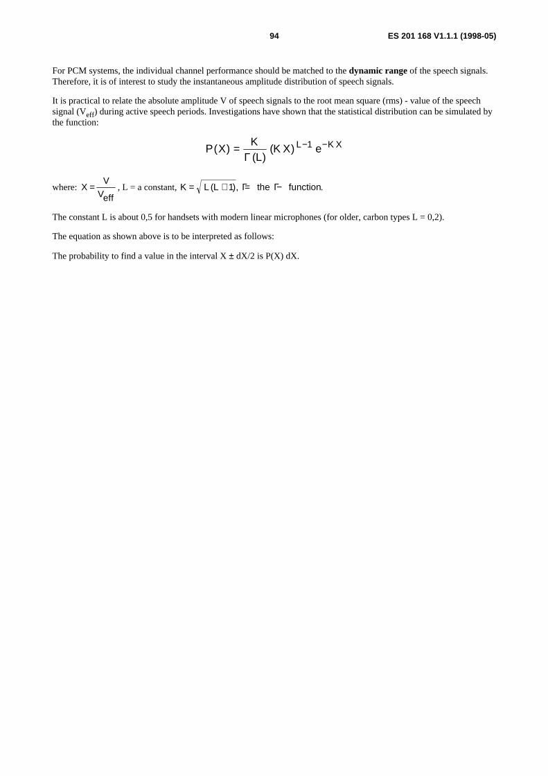
ES 201 168 V1.1.1 (1998-05)94
For PCM systems, the individual channel performance should be matched to the dynamic range of the speech signals.Therefore, it is of interest to study the instantaneous amplitude distribution of speech signals.
It is practical to relate the absolute amplitude V of speech signals to the root mean square (rms) - value of the speechsignal (Veff) during active speech periods. Investigations have shown that the statistical distribution can be simulated bythe function:
P XKL
K X eL K X( )( )
( )= − −Γ
1
where: XV
Veff= , L = a constant,K L L the function= + = −( ), .1 Γ Γ
The constant L is about 0,5 for handsets with modern linear microphones (for older, carbon types L = 0,2).
The equation as shown above is to be interpreted as follows:
The probability to find a value in the interval X ± dX/2 is P(X) dX.
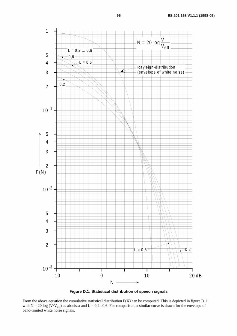
ES 201 168 V1.1.1 (1998-05)95
10 -2
5
4
3
2
10 -3
2
3
4
5
10 -1
2
3
4
5
1
-10 0 10 20
F(N )
dB
N = 20 log Veff
V
R ayle igh-d istribu tion(enve lope o f wh ite no ise)
L = 0 ,50 ,6
0 ,2
L = 0 ,2 ... 0 ,6
L = 0 ,5 0 ,2
N
Figure D.1: Statistical distribution of speech signals
From the above equation the cumulative statistical distribution F(X) can be computed. This is depicted in figure D.1with N = 20 log (V/Veff) as abscissa and L = 0,2...0,6. For comparison, a similar curve is drawn for the envelope ofband-limited white noise signals.

ES 201 168 V1.1.1 (1998-05)96
It is apparent from the figure that speech signals are more "peaky" than white noise. However, for those peak values,that only are exceeded 1 % of the time, the difference is only about 2 dB for the most common value L = 0,5. The 1 %probability value corresponds to N = 12 dB. Subjective tests indicate that this is an acceptable lower limit for speechclipping. Measured absolute peak values of speech lie at about 18 dB above the rms value, but those peaks occur veryinfrequently.
The dynamic range of 64 kbit/s PCM codecs can be described in many ways. One method is to look at the limits for thesignal-to-total distortion ratio as depicted in figure A.5 of CCITT Recommendation G.712 [12] which is reproducedhere in figure D.2. This curve applies for white noise as an input signal (method 1).
33,9
dB
0-55 -40 -34 dB m 0
Inpu t level
Sig
nal-t
o-to
tal d
isto
rtio
n ra
tio
32 ,2
27,626,3
12,6
-27 -3-6
Figure D.2: Signal-to-total distortion ratio as a function of input level (method 1)
One can see from the figure that the signal-to-total distortion ratio curve is flat from -27 dBm0 to -6 dBm0 white noiseinput signal. The upper limit corresponds to the level when peak clipping begins to take effect. However, the decrease insignal-to-total distortion ratio is quite moderate for -3 dBm0 input level.
The peak clipping level for sinusoidal signals is +3 dBm0, i.e. the absolute peak limit level is 6 dBm0. Thus, in therange when the peak clipping begins to take effect for white noise, the margin between the peak limit and the rms valueof the noise lies between:
6 dB + 3 dB = 9 dB and 6 dB + 6 dB =12 dB.
Using speech signals, these values should be increased by 2 dB, giving a desirable margin in the range of 11 dB to14 dB. This corresponds well with the subjectively established value of 12 dB.
What actual speech levels can be expected in the network compared to the nominal speech level?
According to a recent investigations, a "reference talker" (i.e. talking a with -4,7 dBPa mean speech sound pressure atthe MRP) produces during active speech at a 0 dBr point a signal level of:
N = -11 - SLR [dBm0]
where SLR is referred to the 0 dBr point.
By using the above formula, one can compute the margin C at the average speech level against "just noticeable" speechclipping, i.e. at 12 dB higher than the rms value. Also, using the standard deviation of 5 dB for speech levels one canestimate the percentage Pc of talkers who talk so loudly that they are subjected to clipping. Thus:
For the nominal SLR = 7 dB: C = 12 dB, Pc = 0,8 %;
For the minimum SLR = 2 dB: C = 7 dB, Pc = 8%.
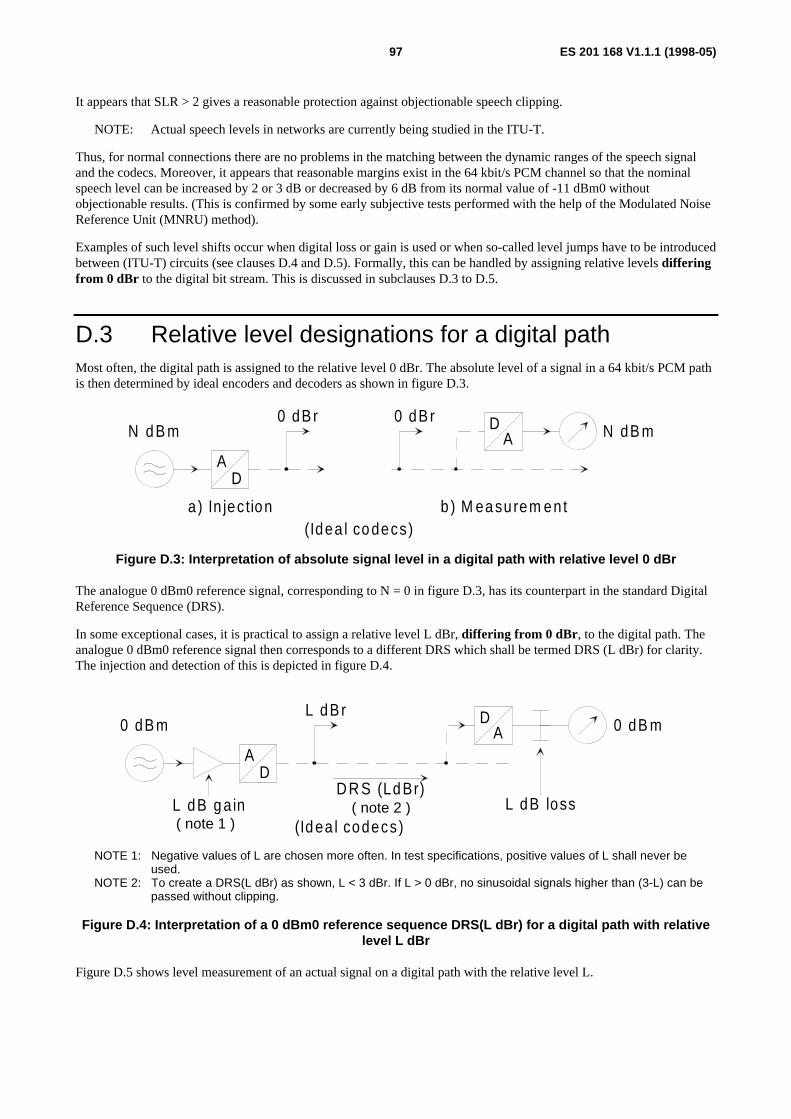
ES 201 168 V1.1.1 (1998-05)97
It appears that SLR > 2 gives a reasonable protection against objectionable speech clipping.
NOTE: Actual speech levels in networks are currently being studied in the ITU-T.
Thus, for normal connections there are no problems in the matching between the dynamic ranges of the speech signaland the codecs. Moreover, it appears that reasonable margins exist in the 64 kbit/s PCM channel so that the nominalspeech level can be increased by 2 or 3 dB or decreased by 6 dB from its normal value of -11 dBm0 withoutobjectionable results. (This is confirmed by some early subjective tests performed with the help of the Modulated NoiseReference Unit (MNRU) method).
Examples of such level shifts occur when digital loss or gain is used or when so-called level jumps have to be introducedbetween (ITU-T) circuits (see clauses D.4 and D.5). Formally, this can be handled by assigning relative levels differingfrom 0 dBr to the digital bit stream. This is discussed in subclauses D.3 to D.5.
D.3 Relative level designations for a digital pathMost often, the digital path is assigned to the relative level 0 dBr. The absolute level of a signal in a 64 kbit/s PCM pathis then determined by ideal encoders and decoders as shown in figure D.3.
AD
N d B m0 dB r D
A0 dB r
N dB m
b ) M ea surem en ta ) In jec tion(Idea l co decs)
Figure D.3: Interpretation of absolute signal level in a digital path with relative level 0 dBr
The analogue 0 dBm0 reference signal, corresponding to N = 0 in figure D.3, has its counterpart in the standard DigitalReference Sequence (DRS).
In some exceptional cases, it is practical to assign a relative level L dBr, differing from 0 dBr , to the digital path. Theanalogue 0 dBm0 reference signal then corresponds to a different DRS which shall be termed DRS (L dBr) for clarity.The injection and detection of this is depicted in figure D.4.
AD
0 dB mL dB r D
A 0 dB m
(Id ea l codecs )L dB g a in L dB loss
D R S (Ld Br)( note 2 )
( note 1 )
NOTE 1: Negative values of L are chosen more often. In test specifications, positive values of L shall never beused.
NOTE 2: To create a DRS(L dBr) as shown, L < 3 dBr. If L > 0 dBr, no sinusoidal signals higher than (3-L) can bepassed without clipping.
Figure D.4: Interpretation of a 0 dBm0 reference sequence DRS(L dBr) for a digital path with relativelevel L dBr
Figure D.5 shows level measurement of an actual signal on a digital path with the relative level L.

ES 201 168 V1.1.1 (1998-05)98
DA N
(Idea l codecs)
DA 2 dBm 0N 1 dB m
N 1 = N 2 + L [dB m ]
L dB rL
Figure D.5: Level measurements on a digital path with L dBr
D.4 Relative levels in equipment design, specification andtesting
D.4.1 Analogue equipmentLarge-capacity FDM (carrier) systems are designed to allow, in an up-modulated band, a long-term average of-15 dBm0 per channel, taking into account signalling, carrier leaks and speech pauses. This corresponds to -11 dBm0actual speech during active periods. (FDM systems with fewer than 240 channels should be designed for a higheraverage power per channel. For instance, a 12-channel FDM system should be able to handle -7,5 dBm0 per channel).
Voice band analogue equipment is in general designed with regard to relative levels so that noise and clipping do notpresent any problems (this implies for instance that the clipping level is higher than 3 dBm0).
D.4.2 Codecs and digital padsFor 64 kbit/s encoders and decoders regarded as components of an equipment, the digital path is taken to represent the0 dBr level reference point (see figure D.6).
0 dB r 0 dB r
a ) E ncoder b ) D ecoder
Figure D.6: 0 dBr level reference points for codecs
The performance specification of codecs, as described in CCITT Recommendation G.712 [12] and elsewhere, is basedon this convention and the parameters are specified with respect to 0 dBm0 values.
In general, when speech path impairments are considered, analogue pads, loss or gain, are to be preferred for level andloss adjustments. However, digital pads often allow more flexibility, especially as they can easily be controlled bysoftware.
Experience has shown that digital pads are robust components that do not require such extensive testing as codecs do.Therefore, it has not been necessary to introduce dBm0-values in their specifications.
When codecs and digital pads are combined in an equipment, any performance testing of the equipment should be donewith the pads disabled, except of course, during pure loss or gain measurements.
The amount of digital loss or gain should be kept within reasonable limits (see clause D.2).
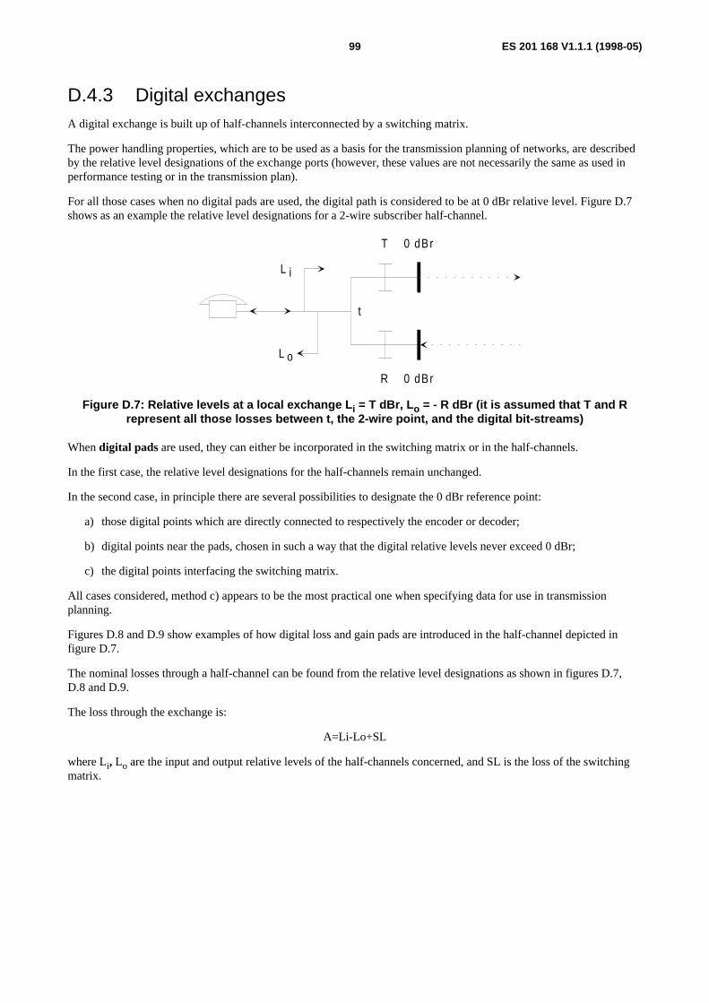
ES 201 168 V1.1.1 (1998-05)99
D.4.3 Digital exchangesA digital exchange is built up of half-channels interconnected by a switching matrix.
The power handling properties, which are to be used as a basis for the transmission planning of networks, are describedby the relative level designations of the exchange ports (however, these values are not necessarily the same as used inperformance testing or in the transmission plan).
For all those cases when no digital pads are used, the digital path is considered to be at 0 dBr relative level. Figure D.7shows as an example the relative level designations for a 2-wire subscriber half-channel.
T 0 dBr
t
R 0 dBr
L i
L o
Figure D.7: Relative levels at a local exchange L i = T dBr, L o = - R dBr (it is assumed that T and Rrepresent all those losses between t, the 2-wire point, and the digital bit-streams)
When digital pads are used, they can either be incorporated in the switching matrix or in the half-channels.
In the first case, the relative level designations for the half-channels remain unchanged.
In the second case, in principle there are several possibilities to designate the 0 dBr reference point:
a) those digital points which are directly connected to respectively the encoder or decoder;
b) digital points near the pads, chosen in such a way that the digital relative levels never exceed 0 dBr;
c) the digital points interfacing the switching matrix.
All cases considered, method c) appears to be the most practical one when specifying data for use in transmissionplanning.
Figures D.8 and D.9 show examples of how digital loss and gain pads are introduced in the half-channel depicted infigure D.7.
The nominal losses through a half-channel can be found from the relative level designations as shown in figures D.7,D.8 and D.9.
The loss through the exchange is:
A=Li-Lo+SL
where Li, Lo are the input and output relative levels of the half-channels concerned, and SL is the loss of the switchingmatrix.

ES 201 168 V1.1.1 (1998-05)100
T 0 d B r
t
R 0 dBrL o
L T
LRLR= - - R
L L T= +Ti
Figure D.8: Relative levels at a local exchange. Digital loss in the half-channel
T 0 d B r
t
R 0 dBrL o
G T
G RG R= - R
L G Ti = T -
Figure D.9: Relative levels at a local exchange. Digital gain in the half-channel
D.5 Relative levels in transmission planning andmaintenance
In transmission planning procedures the overall transmission path is divided into sections in ITU-T vocabulary termedcircuits, each having its own 0 dBr Transmission Reference Point (TRP). Most often circuits connect switching centres.Sometimes also the subscriber line connected to a local exchange is termed circuit. Thus, a circuit is constituted by allpermanently interconnected equipment. In this way maintenance personal have clearly defined segments with fixedtransmission parameters to supervise.
The physical limits of a circuit are sometimes expressed as being situated at "the middle of the exchanges". In this casethe exchange terminating equipment is included in the circuit ending in the exchange test point. This practice is commonin the public networks and dates back to the times when most exchanges were analogue.
However, the transmission planner has other options to subdivide the connection into circuits, provided he clearlydefines the interface. Thus, if the digital switching matrix is designed to introduce loss, the two half-channels 0dBrpoints may be considered as ending of circuits with the switching matrix as a mini circuit in between.
Exceptionally, the "transmission interface" between the two different maintenance organizations does not lie at anexchange. This may be the case when a public and a private network are interconnected. To divide the responsibilitiesclearly, one may designate the public and private links as belonging to two different circuits.
One main problem in transmission planning is to obtain a reasonable matching between expected signal levels and thepower handling capabilities of the equipment used in each circuit. Sometimes also the relative levels at circuitinterconnection points cannot be matched to each other so that "level jumps" have to be introduced.
Regarding a speech level of -11 dBm, at a 0 dBr point, pauses excluded, expected as an average for a large number ofsubscribers, however, field measurements of actual speech levels in TRPs show a very large spread. By this instead oneresorts to some conventions based on general experience.
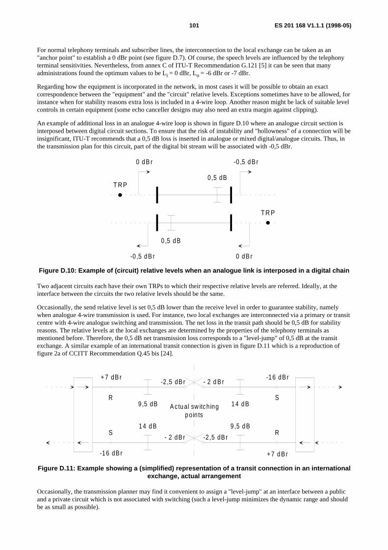
ES 201 168 V1.1.1 (1998-05)101
For normal telephony terminals and subscriber lines, the interconnection to the local exchange can be taken as an"anchor point" to establish a 0 dBr point (see figure D.7). Of course, the speech levels are influenced by the telephonyterminal sensitivities. Nevertheless, from annex C of ITU-T Recommendation G.121 [5] it can be seen that manyadministrations found the optimum values to be Li = 0 dBr, Lo = -6 dBr or -7 dBr.
Regarding how the equipment is incorporated in the network, in most cases it will be possible to obtain an exactcorrespondence between the "equipment" and the "circuit" relative levels. Exceptions sometimes have to be allowed, forinstance when for stability reasons extra loss is included in a 4-wire loop. Another reason might be lack of suitable levelcontrols in certain equipment (some echo canceller designs may also need an extra margin against clipping).
An example of additional loss in an analogue 4-wire loop is shown in figure D.10 where an analogue circuit section isinterposed between digital circuit sections. To ensure that the risk of instability and "hollowness" of a connection will beinsignificant, ITU-T recommends that a 0,5 dB loss is inserted in analogue or mixed digital/analogue circuits. Thus, inthe transmission plan for this circuit, part of the digital bit stream will be associated with -0,5 dBr.
-0 ,5 d B r
0 ,5 dB
T R P
0 dB r
0 ,5 d B
-0 ,5 d B r
T R P
0 d B r
Figure D.10: Example of (circuit) relative levels when an analogue link is interposed in a digital chain
Two adjacent circuits each have their own TRPs to which their respective relative levels are referred. Ideally, at theinterface between the circuits the two relative levels should be the same.
Occasionally, the send relative level is set 0,5 dB lower than the receive level in order to guarantee stability, namelywhen analogue 4-wire transmission is used. For instance, two local exchanges are interconnected via a primary or transitcentre with 4-wire analogue switching and transmission. The net loss in the transit path should be 0,5 dB for stabilityreasons. The relative levels at the local exchanges are determined by the properties of the telephony terminals asmentioned before. Therefore, the 0,5 dB net transmission loss corresponds to a "level-jump" of 0,5 dB at the transitexchange. A similar example of an international transit connection is given in figure D.11 which is a reproduction offigure 2a of CCITT Recommendation Q.45 bis [24].
A c tu al sw itch ingp o in ts
S
R
-1 6 dB r
+ 7 d B r
1 4 d B
9 ,5 d B
- 2 d B r
-2 ,5 dB r
-2 ,5 dB r
- 2 dB r
9 ,5 dB
1 4 d B
+ 7 dB r
R
S
-1 6 dB r
Figure D.11: Example showing a (simplified) representation of a transit connection in an internationalexchange, actual arrangement
Occasionally, the transmission planner may find it convenient to assign a "level-jump" at an interface between a publicand a private circuit which is not associated with switching (such a level-jump minimizes the dynamic range and shouldbe as small as possible).

ES 201 168 V1.1.1 (1998-05)102
Note that, in general, the total loss of a connection made up of several circuits should be determined by adding the lossesof the individual circuits, and not by taking differences in relative levels between the input and the output of theconnection ports (the latter method is only valid when all the consistent circuits are digital and not using digital signalprocessing).
With regard to digital parameters in a complete connection, the transmission planner should also consider the sum ofqdu’s, the total amount of digital loss or gain introduced, and the sum of all level-jumps (see clause D.2).

ES 201 168 V1.1.1 (1998-05)103
Annex E (informative):Impedances and relative levels used up to now by thevarious European administrationsThe corresponding values for the various L2, K2, M2, and M4 interfaces are listed in tables E.1 to E.4, respectively. Theconfiguration of the PBX input impedance and of the test network for trans balance return loss is given in figure E.1.
Rp
Cp
Rs
Figure E.1: Configuration of the PBX Input Impedance and the Test Network for TBRL
Table E.1: L2 interface - Values for impedance, the test network for TBRL, and the relative input andoutput levels specified by different administrations
Country PBXInput Impedance
Test Network forTerminal
Balance Return Loss
RelativeInput/output levels
Rs[Ω]
Rp[Ω]
Cp[nF]
Rs[Ω]
Rp[Ω]
Cp[nF]
Li[dBr]
Lo[dBr]
Austria 220 820 115 600 0 0 0 -7600 0 0 600 0 0 0 -7
Belgiumshort lines≤ 2,5 km 150 830 72 600 0 0 0 -7long lines > 2,5 km 150 830 72 150 830 72 0 -7Denmark 300 1 000 220 400 500 330 0 -6Finland 270 910 120 390 620 100 0 -7
270 910 120 270 1200 120 0 -7France1) 215 1 000 137 600 0 0 -1,9 -8,9
(180) (910) (150) 600 0 0 (-1,4) (-8,4)Germany 220 820 115 220 820 115 0 -7
option 220 820 115 220 820 115 +3 -10Greece 400 500 50 220 820 115 0 -7Italy 180 630 60 0 750 18 0 -7Netherlands NS 340 422 100 0 -7Norway2) 120 820 110 120 820 110 +2 -5
120 820 110 120 820 110 +7 -11Portugal NS NS under studySlovakia 220
600820
0115
0220600
8200
1150
0+3
-7-10
Spain 220 820 120 220 820 120 0 -7Sweden3) 200 1 000 100 0 900 30 0 -5Switzerland 220 820 115 220 820 115 0 -6,5UK (BT) 300 1 000 220 370 620 310 ≥ +3 NSNOTE 1: Values in brackets shall not be used in the future.NOTE 2: In Norway, for connections to/from digital exchange lines, the relative levels may have to be changed to
Lo = -11 dBr and Li = + 7 dBr to satisfy the Recommendations in ETR 004 [1].NOTE 3: On international connections 2 dB digitally implemented loss is added at the international switching centre in
the receiving transmission direction.
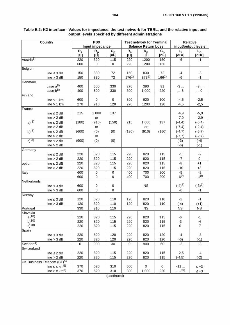
ES 201 168 V1.1.1 (1998-05)104
Table E.2: K2 interface - Values for impedance, the test network for TBRL, and the relative input andoutput levels specified by different administrations
Country PBXInput impedance
Test network for TerminalBalance Return Loss
Relativeinput/output levels
Rs[Ω]
Rp[Ω]
Cp[nF]
Rs[Ω]
Rp[Ω]
Cp[nF]
Li[dBr]
Lo[dBr]
Austria1) 220 820 115 220 1200 150 -6 -1600 0 0 220 1200 150
Belgiumline ≤ 3 dB 150 830 72 150 830 72 -4 -3line > 3 dB 150 830 72 1762) 8732) 1662) -6 -1
Denmarkcase a8) 400 500 330 270 390 91 -3 ... -3 ...case b8) 400 500 330 300 1 000 220 ... 6 ... 0
Finlandline ≤ 1 km 600 0 0 390 620 100 -4,5 -2,5line > 1 km 270 910 120 270 1200 120 -4,5 -2,5
Franceline ≤ 2 dB 215 1 000 137 -4,9 -5,9line > 2 dB or -7,9 -2,9
a) 3) line ≤ 2 dB (180) (910) (150) 215 1 000 137 (-4,4) (-5,4)line > 2 dB or or (-7,4) (-2,4)
b) 3) line ≤ 2 dB (600) (0) (0) (180) (910) (150) (-4,7) (-5,7)line > 2 dB or (-7,7) (-2,7)
c) 3) line ≤ 2 dB (900) (0) (0) (-3) (-4)line > 2 dB (-6) (-1)
Germanyline ≤ 2 dB 220 820 115 220 820 115 -5 -2line > 2 dB 220 820 115 220 820 115 -7 0
option line ≤ 2 dB 220 820 115 220 820 115 -8 +1line > 2 dB 220 820 115 220 820 115 -10 +3
Italy 600 0 0 400 700 200 -5 -2600 0 0 400 700 200 -69) -19)
Netherlandsline ≤ 3 dB 600 0 0 NS (-4)7) (-3)7)
line > 3 dB 600 0 0 -6 -1Norway
line ≤ 3 dB 120 820 110 120 820 110 -2 -1line > 3 dB 120 820 110 120 820 110 (-4) (+1)
Portugal 330 910 110 NS NS NSSlovakia
a)10)
b)10)
c)10)
220220220
820820820
115115115
220220220
820820820
115115115
-6-30
-1-4-7
Spainline ≤ 3 dB 220 820 120 220 820 120 -4 -3line > 3 dB 220 820 120 220 820 120 (-6) (-1)
Sweden4) 0 900 30 0 900 60 -2 -3Switzerland
line ≤ 2 dB 220 820 115 220 820 115 -2,5 -4line > 2 dB 220 820 115 220 820 115 (-4,5) (-2)
UK Business Telecom (BT)5)
line ≤ x km5) 370 620 310 600 0 0 -11 ... ≤ +3line > x km5) 370 620 310 300 1 000 220 ... -36) ≤ +3
(continued)
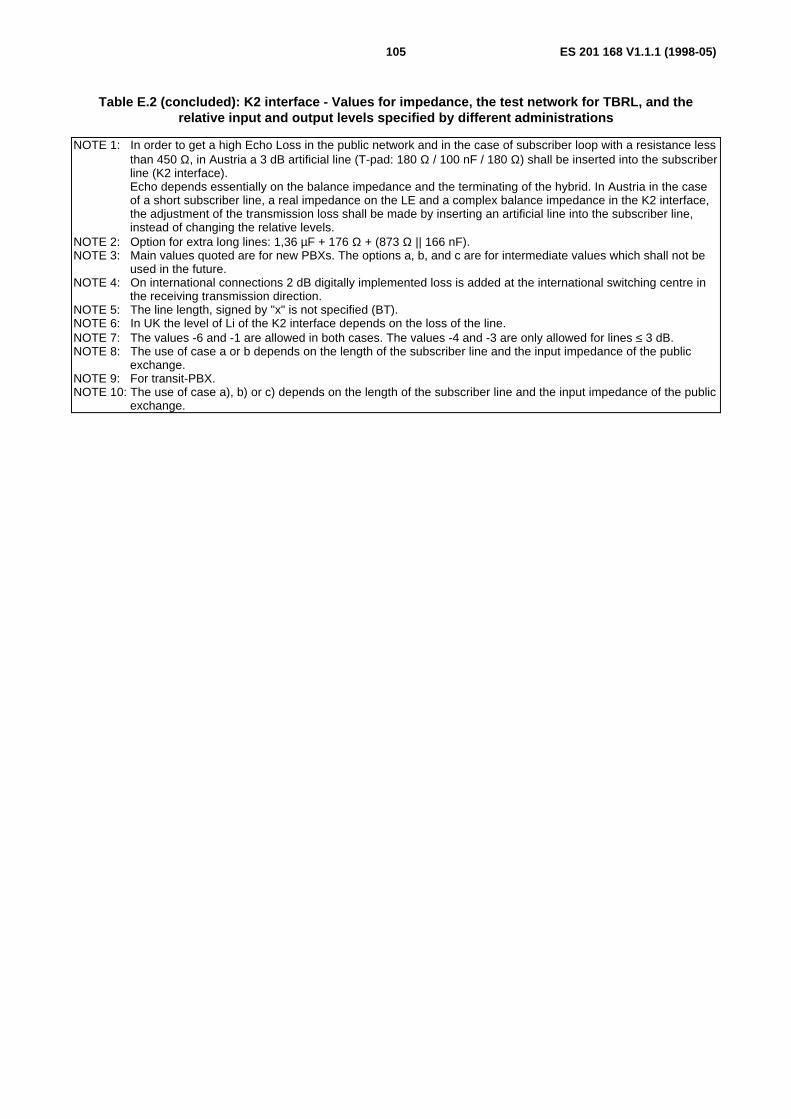
ES 201 168 V1.1.1 (1998-05)105
Table E.2 (concluded): K2 interface - Values for impedance, the test network for TBRL, and therelative input and output levels specified by different administrations
NOTE 1: In order to get a high Echo Loss in the public network and in the case of subscriber loop with a resistance lessthan 450 Ω, in Austria a 3 dB artificial line (T-pad: 180 Ω / 100 nF / 180 Ω) shall be inserted into the subscriberline (K2 interface).Echo depends essentially on the balance impedance and the terminating of the hybrid. In Austria in the caseof a short subscriber line, a real impedance on the LE and a complex balance impedance in the K2 interface,the adjustment of the transmission loss shall be made by inserting an artificial line into the subscriber line,instead of changing the relative levels.
NOTE 2: Option for extra long lines: 1,36 µF + 176 Ω + (873 Ω || 166 nF).NOTE 3: Main values quoted are for new PBXs. The options a, b, and c are for intermediate values which shall not be
used in the future.NOTE 4: On international connections 2 dB digitally implemented loss is added at the international switching centre in
the receiving transmission direction.NOTE 5: The line length, signed by "x" is not specified (BT).NOTE 6: In UK the level of Li of the K2 interface depends on the loss of the line.NOTE 7: The values -6 and -1 are allowed in both cases. The values -4 and -3 are only allowed for lines ≤ 3 dB.NOTE 8: The use of case a or b depends on the length of the subscriber line and the input impedance of the public
exchange.NOTE 9: For transit-PBX.NOTE 10: The use of case a), b) or c) depends on the length of the subscriber line and the input impedance of the public
exchange.
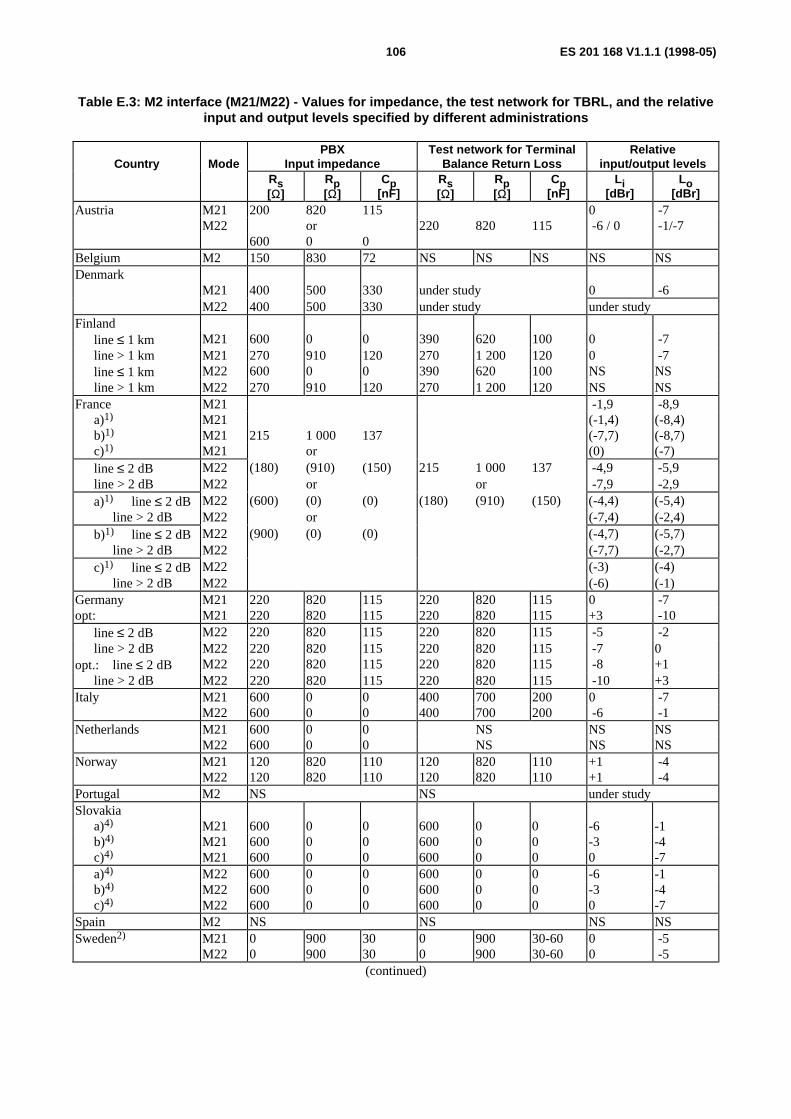
ES 201 168 V1.1.1 (1998-05)106
Table E.3: M2 interface (M21/M22) - Values for impedance, the test network for TBRL, and the relativeinput and output levels specified by different administrations
Country ModePBX
Input impedanceTest network for Terminal
Balance Return LossRelative
input/output levelsRs[Ω]
Rp[Ω]
Cp[nF]
Rs[Ω]
Rp[Ω]
Cp[nF]
Li[dBr]
Lo[dBr]
Austria M21 200 820 115 0 -7M22 or 220 820 115 -6 / 0 -1/-7
600 0 0Belgium M2 150 830 72 NS NS NS NS NSDenmark
M21 400 500 330 under study 0 -6M22 400 500 330 under study under study
Finlandline ≤ 1 km M21 600 0 0 390 620 100 0 -7line > 1 km M21 270 910 120 270 1 200 120 0 -7line ≤ 1 km M22 600 0 0 390 620 100 NS NSline > 1 km M22 270 910 120 270 1 200 120 NS NS
France M21 -1,9 -8,9 a)1) M21 (-1,4) (-8,4)
b)1) M21 215 1 000 137 (-7,7) (-8,7)c)1) M21 or (0) (-7)line ≤ 2 dB M22 (180) (910) (150) 215 1 000 137 -4,9 -5,9line > 2 dB M22 or or -7,9 -2,9a)1) line ≤ 2 dB M22 (600) (0) (0) (180) (910) (150) (-4,4) (-5,4)
line > 2 dB M22 or (-7,4) (-2,4)b)1) line ≤ 2 dB M22 (900) (0) (0) (-4,7) (-5,7)
line > 2 dB M22 (-7,7) (-2,7)c)1) line ≤ 2 dB M22 (-3) (-4)
line > 2 dB M22 (-6) (-1)Germany M21 220 820 115 220 820 115 0 -7opt: M21 220 820 115 220 820 115 +3 -10
line ≤ 2 dB M22 220 820 115 220 820 115 -5 -2line > 2 dB M22 220 820 115 220 820 115 -7 0
opt.: line ≤ 2 dB M22 220 820 115 220 820 115 -8 +1line > 2 dB M22 220 820 115 220 820 115 -10 +3
Italy M21 600 0 0 400 700 200 0 -7M22 600 0 0 400 700 200 -6 -1
Netherlands M21 600 0 0 NS NS NSM22 600 0 0 NS NS NS
Norway M21 120 820 110 120 820 110 +1 -4M22 120 820 110 120 820 110 +1 -4
Portugal M2 NS NS under studySlovakia
a)4) M21 600 0 0 600 0 0 -6 -1b)4) M21 600 0 0 600 0 0 -3 -4c)4) M21 600 0 0 600 0 0 0 -7a)4) M22 600 0 0 600 0 0 -6 -1b)4) M22 600 0 0 600 0 0 -3 -4c)4) M22 600 0 0 600 0 0 0 -7
Spain M2 NS NS NS NSSweden2) M21 0 900 30 0 900 30-60 0 -5
M22 0 900 30 0 900 30-60 0 -5(continued)
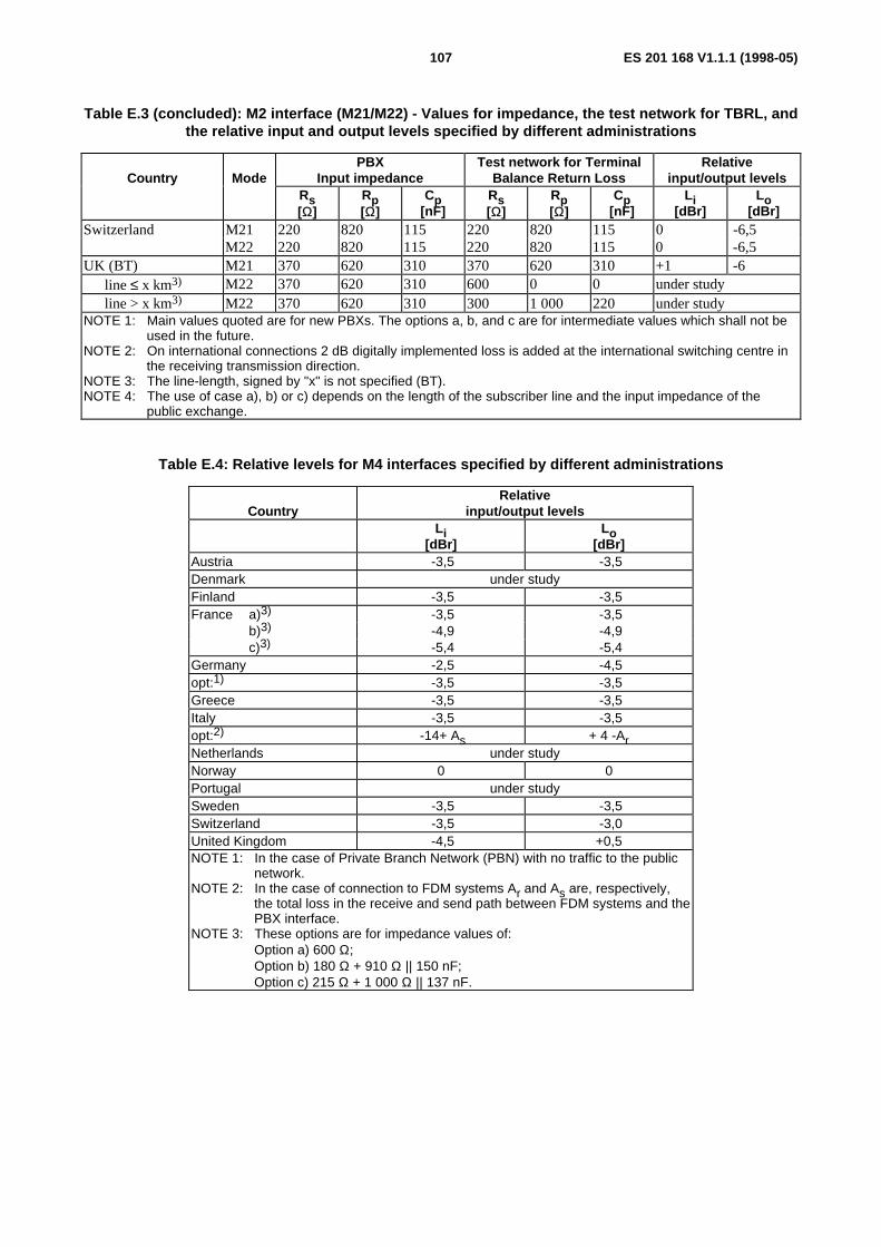
ES 201 168 V1.1.1 (1998-05)107
Table E.3 (concluded): M2 interface (M21/M22) - Values for impedance, the test network for TBRL, andthe relative input and output levels specified by different administrations
Country ModePBX
Input impedanceTest network for Terminal
Balance Return LossRelative
input/output levelsRs[Ω]
Rp[Ω]
Cp[nF]
Rs[Ω]
Rp[Ω]
Cp[nF]
Li[dBr]
Lo[dBr]
Switzerland M21 220 820 115 220 820 115 0 -6,5M22 220 820 115 220 820 115 0 -6,5
UK (BT) M21 370 620 310 370 620 310 +1 -6line ≤ x km3) M22 370 620 310 600 0 0 under studyline > x km3) M22 370 620 310 300 1 000 220 under study
NOTE 1: Main values quoted are for new PBXs. The options a, b, and c are for intermediate values which shall not beused in the future.
NOTE 2: On international connections 2 dB digitally implemented loss is added at the international switching centre inthe receiving transmission direction.
NOTE 3: The line-length, signed by "x" is not specified (BT).NOTE 4: The use of case a), b) or c) depends on the length of the subscriber line and the input impedance of the
public exchange.
Table E.4: Relative levels for M4 interfaces specified by different administrations
CountryRelative
input/output levelsLi
[dBr]Lo
[dBr]Austria -3,5 -3,5Denmark under studyFinland -3,5 -3,5France a)3) -3,5 -3,5
b)3) -4,9 -4,9c)3) -5,4 -5,4
Germany -2,5 -4,5opt:1) -3,5 -3,5Greece -3,5 -3,5Italy -3,5 -3,5opt:2) -14+ As + 4 -ArNetherlands under studyNorway 0 0Portugal under studySweden -3,5 -3,5Switzerland -3,5 -3,0United Kingdom -4,5 +0,5NOTE 1: In the case of Private Branch Network (PBN) with no traffic to the public
network.NOTE 2: In the case of connection to FDM systems Ar and As are, respectively,
the total loss in the receive and send path between FDM systems and thePBX interface.
NOTE 3: These options are for impedance values of:Option a) 600 Ω;Option b) 180 Ω + 910 Ω || 150 nF;Option c) 215 Ω + 1 000 Ω || 137 nF.
ES 201 168 V1.1.1 (1998-05)108
Annex F (informative):Bibliography
- I-ETS 300 003 (1991): "Business Telecommunications (BT); Transmission characteristics of digital PrivateAutomatic Branch Exchanges (PABXs)".
- I-ETS 300 004 (1991): "Business Telecommunications (BT); Transmission characteristics at 2-wire analogueinterfaces of a digital Private Automatic Branch Exchange (PABX)".
- I-ETS 300 005 (1991): "Business Telecommunications (BT); Transmission characteristics at 4-wire analogueinterfaces of a digital Private Automatic Branch Exchange (PABX)".
- I-ETS 300 006 (1991): "Business Telecommunications (BT); Transmission characteristics at digital interfaces ofa digital Private Automatic Branch Exchange (PABX)".
- ETR 250 (1996): "Transmission and Multiplexing (TM); Speech communication quality from mouth to ear for3,1 kHz handset telephony across networks".
- ITU-T Recommendation G.100 (1993): "Definitions used in Recommendations on general characteristics ofinternational telephone connections and circuits".
- ITU-T Recommendation G.117 (1996): "Transmission aspects of unbalance about earth (definitions andmethods)".
- CCITT Fascicle III.3 (Orange Book, 1980) Supplement 13 to the G Series: "Noise at the terminals of batterysupply".

ES 201 168 V1.1.1 (1998-05)109
History
Document history
V1.1.1 March 1998 Membership Approval Procedure MV 9819: 1998-03-10 to 1998-05-08
V1.1.1 May 1998 Publication
ISBN 2-7437-2181-2Dépôt légal : Mai 1998