Embed Size (px)
Citation preview
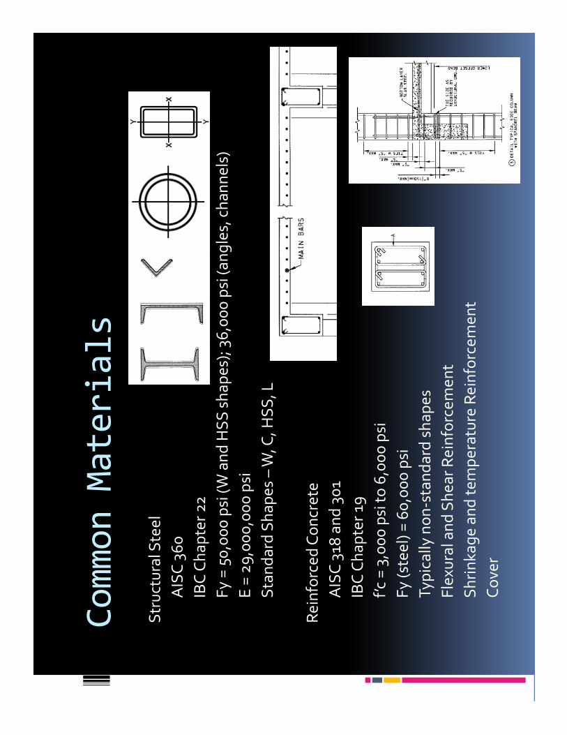
Common Materials
Str
uct
ura
l Ste
el
AIS
C 3
60
IBC
Ch
ap
ter
22
Fy
= 5
0,0
00
psi
(W
an
d H
SS
sh
ap
es)
; 36
,00
0 p
si (
an
gle
s, c
ha
nn
els
)
E =
29
,00
0,0
00
psi
Sta
nd
ard
Sh
ap
es
–W
, C, H
SS
, L
Re
info
rce
d C
on
cre
te
AIS
C 3
18 a
nd
30
1
IBC
Ch
ap
ter
19
f’c
= 3
,00
0 p
si t
o 6
,00
0 p
si
Fy
(ste
el)
= 6
0,0
00
psi
Ty
pic
ally
no
n-s
tan
da
rd s
ha
pe
s
Fle
xura
l an
d S
he
ar
Re
info
rce
me
nt
Sh
rin
ka
ge
an
d t
em
pe
ratu
re R
ein
forc
em
en
t
Co
ver

Common Materials
Re
info
rce
d M
aso
nry
AIS
C 5
30
IBC
Ch
ap
ter
21
f’m
= 1
,50
0p
si t
o 3
,00
0 p
si
Fy
(ste
el)
= 6
0,0
00
psi
Co
mp
osi
te p
rop
ert
ies
of
cmu
, gro
ut,
mo
rta
r a
nd
ste
el
Re
info
rce
me
nt
can
be
at
face
or
cen
tere
d in
wa
ll
Bo
nd
be
am
s
Wo
od Na
tio
na
l De
sig
n S
pe
cifi
cati
on
(N
DS
)
IBC
Ch
ap
ter
23
Un
iqu
e d
esi
gn
me
tho
ds
du
e t
o n
on
-un
ifo
rm p
rop
ert
ies
(Fb
, Fv,
Fc ll
, Fc,
Fc b bbb
, Em
in)
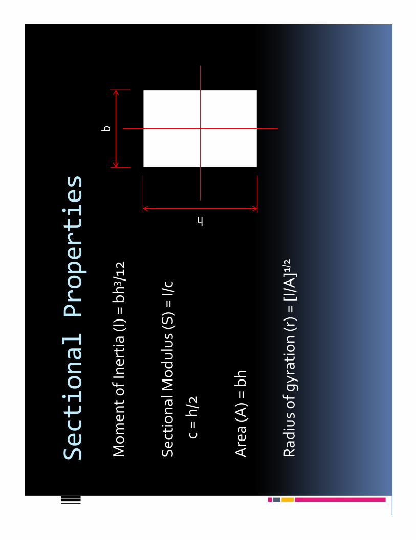
Sectional Properties
Mo
me
nt
of
Ine
rtia
(I)
= b
h3 /1
2
Se
ctio
na
l Mo
du
lus
(S)
= I/
c
c =
h/2
Are
a (
A)
= b
h
Ra
diu
s o
f g
yra
tio
n (
r) =
[I/
A]1/
2
b
h

Foundations
De
ep
Ca
isso
ns
(Dri
lled
Pie
r)A
ug
er-
cast
Pile
s
Lo
ad
Tra
nsf
er
Ty
pe
s
Oth
er
Ty
pe
s: M
icro
-pile
s, d
rive
n p
iles

Foundations
Sh
allo
w
Wa
ll F
oo
tin
g
Dif
fere
nti
al S
ett
lem
en
t
So
il S
tab
iliza
tio
n –
Ag
gre
ga
te P
iers
, CM
Cs,
So
il C
om
pa
ctio
n, e
tc.

Gravity Forces/Systems
Liv
e, S
no
w, D
ea
d, S
oil,
an
d H
yd
rost
ati
c
Liv
e L
oa
d R
ed
uct
ion
(L
LR
)
LL
R =
Lo[2
5 +
15
/(K
LLA
T)]
1/2
Lo
= U
nre
du
ced
Liv
e L
oa
d
AT
= T
rib
uta
ry A
rea
KL
L=
Liv
e L
oa
d E
lem
en
t F
act
or
Fle
xure
: Fb
= M
/S
Sh
ea
r: F
v=
V/A
De
fle
ctio
n:
∆ ∆∆∆
wL
2/8
wL
/2
5w
L4(1
2)3 /3
84
EI
Un
ifo
rm L
oa
d
Vle
ft=
Pb
/L
Vri
gh
t=
Pa
/L
PL
3 (12
)3 /48
EI
(P a
t ce
nte
r o
f b
ea
m: a
=b
)
Pa
b/L
Po
int
Lo
ad
P
ba
L

Beams
Tru
sse
s / J
ois
ts
Kin
g P
ost
Tru
ssP
ratt
Tru
ss
Ho
we
Tru
ss
Sta
nd
ard
Ste
el J
ois
t

Beams
Co
mp
osi
te B
ea
ms
ST
EE
L
SIP
s P
an
els
Oth
er
Ty
pe
s In
clu
de
:
Pre
-str
ess
ed
an
d P
ost
-Te
nsi
on
ed
Co
ncr
ete
Sta
nd
ard
Re
info
rce
d C
on
cre
te
Re
info
rce
d M
aso
nry

Columns
f c=
P/A
f cis
de
pe
nd
en
t u
po
n
Sle
nd
ern
ess
Ra
tio
= K
L/r
Sm
alle
r w
ill in
cre
ase
th
e f
c
K -
Eff
ect
ive
Le
ng
th F
act
or

LRFD vs. ASD
Lo
ad
Re
sist
an
ce F
act
or
De
sig
n
Ult
ima
te S
tre
ng
th M
eth
od
Fa
cto
rs p
lace
d o
n L
oa
ds
an
d S
tre
sse
d t
o C
ap
aci
ty
Liv
e L
oa
d =
1.6
an
d D
ea
d L
oa
d =
1.2
Allo
wa
ble
Str
ess
De
sig
n
Me
mb
er
stre
sse
d t
o p
erc
en
tag
e o
f yi
eld
str
ess
Ste
el:
Fb
= 0
.66
Fy
an
d F
y=
0.4
0 F
y
Wo
od
: Du
rati
on
Fa
cto
rs (C
d):
Liv
e =
1.0
, De
ad
= 0
.9, W
ind
= 1
.6, S
no
w =
1.2
Ind
ust
ry h
as
mo
ved
to
LR
FD

Loads vs. Structural Systems
WO
OD
BE
AM
S/
JOIS
TS
ST
EE
L A
ND
CO
NC
RE
TE
JO
IST
S
ON
E-W
AY
CO
NC
RE
TE
(SL
AB
S A
ND
BE
AM
S)
ST
EE
L B
EA
M
CO
MP
OS
ITE
ST
EE
L B
EA
MS
TW
O-W
AY
CO
NC
RE
TE
SY
ST
EM
S
LO
NG
SP
AN
TR
US
SE
S
LO
AD
INC
RE
AS
E
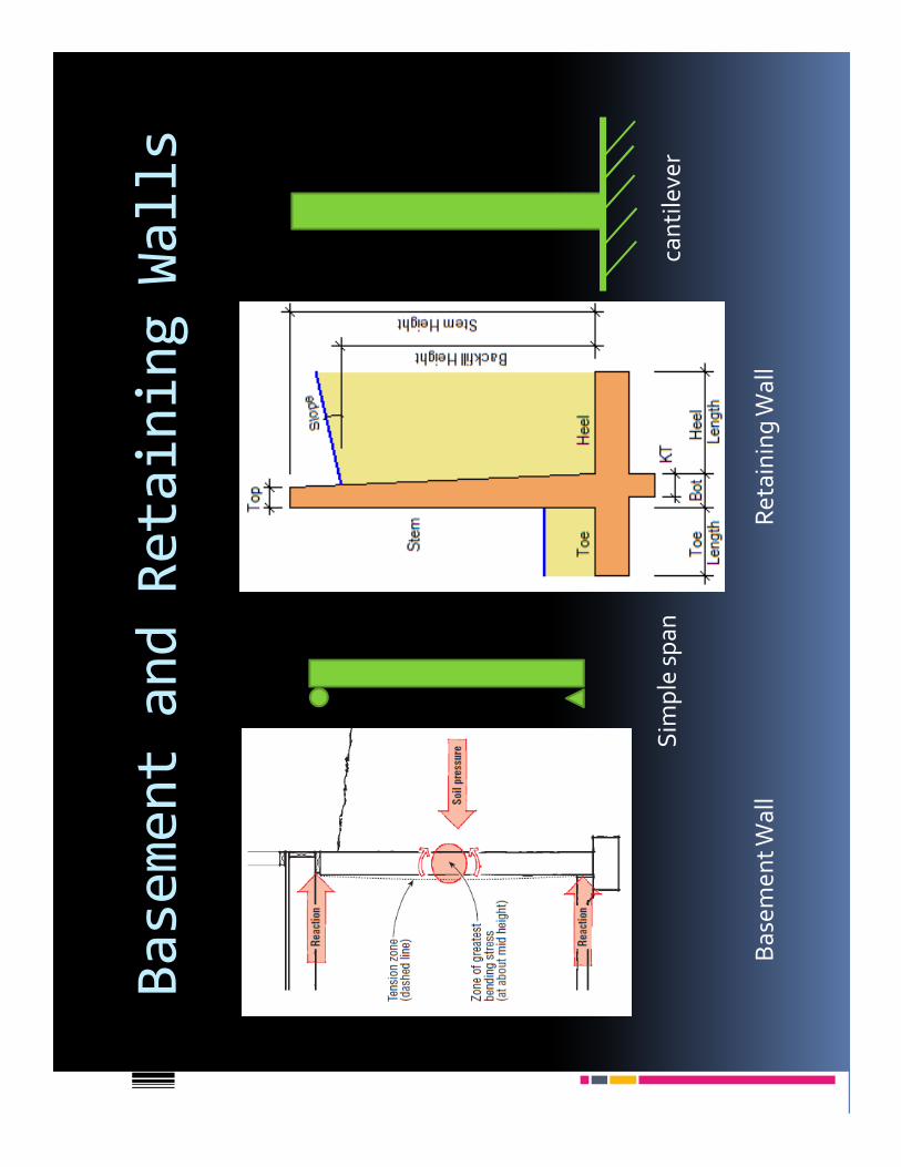
Basement and Retaining Walls
Ba
sem
en
t W
all
Re
tain
ing
Wa
ll
Sim
ple
sp
an
can
tile
ver
Wind
Ma
in W
ind
Fo
rce
Re
sist
ing
Sy
ste
ms
vs. C
om
po
ne
nts
an
d
Cla
dd
ing
Lo
ad
s a
re b
ase
d u
po
n h
isto
rica
l an
aly
sis
an
d p
rob
ab
ility
90
pe
rce
nt
of
U.S
. de
sig
ne
d f
or
90
mp
h
Fa
cto
rs w
hic
h a
ffe
ct p
ress
ure
:
Sp
eci
al c
on
sid
era
tio
ns:
Pre
ssu
res
incr
ea
se w
ith
bu
ildin
g h
eig
ht
No
n-e
ncl
ose
d s
tru
ctu
res,
esc
arp
me
nts
, pa
rap
ets
,
ove
rha
ng
s, e
tc.
Imp
ort
an
ce f
act
or
Bu
ildin
g h
eig
ht
Wa
ll/ro
of
zon
es
(co
mp
./cl
ad
din
g)
Exp
osu
re C
ate
go
ry

Wind
Win
d b
ase
sh
ea
r (V
) =
win
d a
rea
x w
ind
pre
ssu
re
Win
dw
ard
an
d le
ew
ard
pre
ssu
res
are
incl
ud
ed
Co
llect
ed
at
the
flo
or
dia
ph
rag
ms
�h
ttp
s://
cou
rse
s.ci
t.co
rne
ll.e
du
/arc
h2
64
/ca
lcu
lato
rs/s
eis
mic
-win
d/i
nd
ex.
htm
l

Seismic
Ne
ed
to
un
de
rsta
nd
:
Sit
e C
lass
A t
hro
ug
h F
Occ
up
an
cy C
ate
go
ry
Se
ism
ic D
esi
gn
Ca
teg
ory
Imp
ort
an
ce F
act
or
Se
ism
ic F
orc
e-R
esi
stin
g S
yst
em
Re
spo
nse
Mo
dif
ica
tio
n F
act
or
Se
ism
ic b
ase
sh
ea
r (V
) =
CsW
(Eq
uiv
ale
nt
La
tera
l Fo
rce
Me
tho
d)
Se
ism
ic r
esp
on
se c
oe
ffic
ien
t (C
s) =
SD
S/(
R/I
) b
ut
no
t <
0.0
1
SD
S=
De
sig
n S
pe
ctra
l Acc
ele
rati
on
R =
Re
spo
nse
Mo
dif
ica
tio
n F
act
or
I =
Se
ism
ic O
ccu
pa
ncy
Imp
ort
an
ce F
act
or
W =
Eff
ect
ive
Se
ism
ic W
eig
ht
(in
clu
de
s d
ea
d, %
of
LL
, pa
rtit
ion
, he
avy
sn
ow
loa
ds)
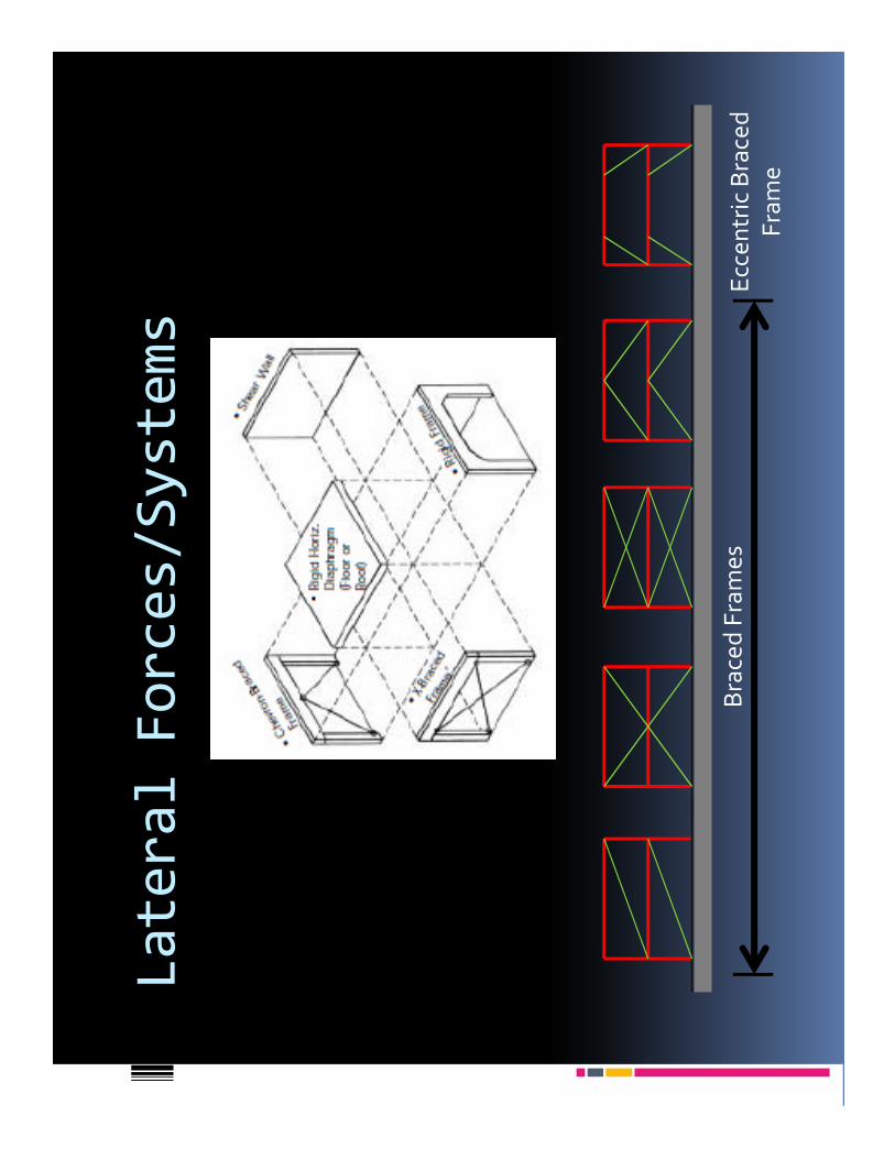
Lateral Forces/Systems
Bra
ced
Fra
me
sE
cce
ntr
ic B
race
d
Fra
me

Base Shear
P P P P
4P
4/3
P
P P P P
2/3
P4
/3P
2/3
P
Po
rta
l Me
tho
d
(Mo
me
nt
Fra
me
)

P-Delta (P
∆) Effect
P∆
about a structure
P-δ
eff
ect
(P
-"sm
all-
de
lta“
) , i
s a
sso
cia
ted
wit
h lo
cal d
efo
rma
tio
n
rela
tive
to
th
e e
lem
en
t ch
ord
be
twe
en
en
d n
od
es.
P-Δ
eff
ect
(P-"
big
-de
lta“
), is
ass
oci
ate
d w
ith
dis
pla
cem
en
ts r
ela
tive
to
me
mb
er
en
ds.
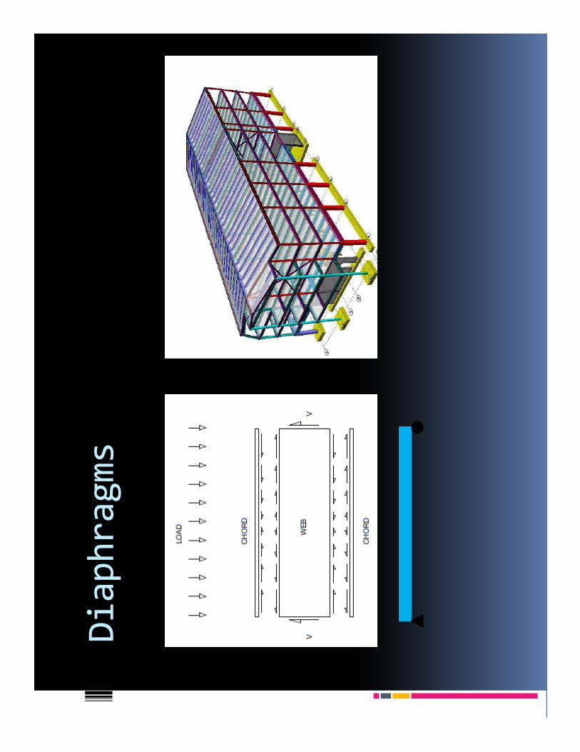
Diaphragms

Center of Mass and Center of Rigidity
L/2
L/2
Shear wall
Shear wall
Ce
nte
r o
f R
igid
ity
L/2
L/2
Shear wall
ShearwallC
en
ter
of
Ma
ss
> L
/2<
L/2
e
De
sig
n s
ho
uld
min
imiz
e e
cce
ntr
icit
y (e
) in
ord
er
to r
ed
uce
ad
dit
ion
al
she
ar
stre
ss a
s a
re
sult
of
tors
ion
(“t
wis
tin
g”)

Drift
Inte
r-st
ory
an
d o
vera
ll d
rift
sh
all
be
lim
ite
d f
or
serv
ice
ab
ility
re
qu
ire
me
nts
. P
rim
ary
co
nsi
de
rati
on
will
be
fa
çad
e m
ate
ria
ls.
H/4
00
fo
r m
aso
nry
fa
cad
es
H/2
00
fo
r cu
rta
in w
all,
EIF
S a
nd
me
tal p
an
el f
aca
de
s

Examples
Qu
est
ion
s o
n t
he
sa
mp
le t
est
?
Ad
dit
ion
al E
xam
ple
s…..

Example 1
12
12
AB
C
P =
75
kip
s

Example 2
12
12
AB
C
P =
75
kip
s
D

Example 2
12
12
AB
C
P =
75
kip
s
D

Example 3
6,0
00
po
un
ds
20
’
I = 250 in4
I = 250 in4
I = 2
50 in
4
20’
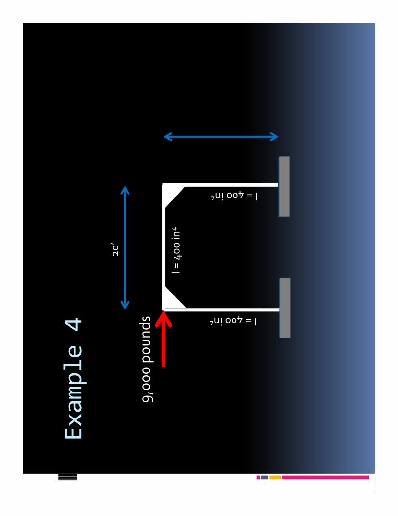
Example 4
9,0
00
po
un
ds I = 400 in4
I = 400 in4
I = 4
00
in4
20
’

Example 5
PP
P
AB
C

Example 6
A2L B
1 1
/2L

Example 7
A B C
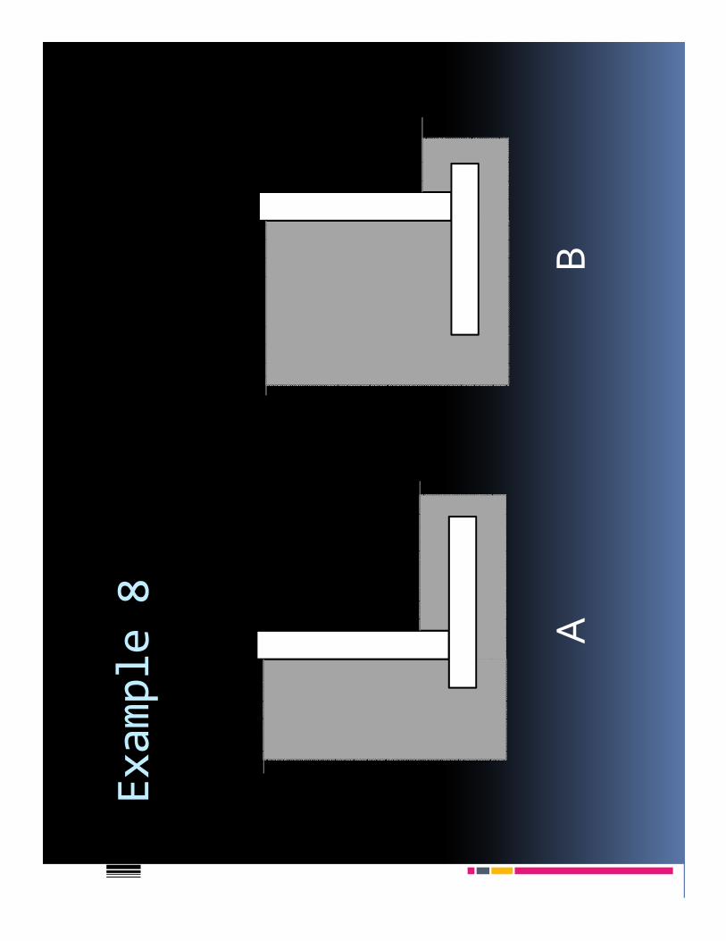
Example 8
AB
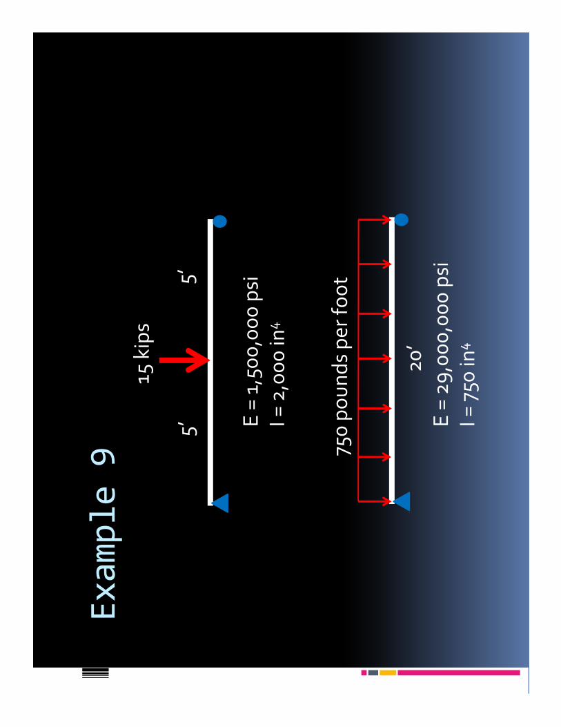
Example 9
15 k
ips
5’
5’ E
= 1
,50
0,0
00
psi
I = 2
,00
0 in
4
750
po
un
ds
pe
r fo
ot
20
’
E =
29
,00
0,0
00
psi
I = 7
50 in
4

Example 10
Y
X
Y
X
10’15’
P