Embed Size (px)
Citation preview
May 2014Application Reference EN020001
5.2.1Do
cum
ent
Hinkley Point C Connection Project
Environmental StatementProject Need and Alternatives
Regulation 5(2)(a) of the Infrastructure Planning (Applications: Prescribed Forms and Procedure) Regulations 2009
Hinkley Point C Connection Project
ENVIRONMENTAL STATEMENT – MAY 2014
VOLUME 5.2.1, CHAPTER 2 – PROJECT NEED AND ALTERNATIVES

Hinkley Point C Connection Project – Volume 5.2.1
2
Document Control
Document Properties
Organisation National Grid
Author Ken Murray, National Grid and Chris Chadwick, Amec
Approved By Ken Murray, National Grid
Title Environmental Statement Chapter 2 – Project Need and Alternatives
Document Reference Volume 5.2.1
Date Version Status Description/Changes
14/05/14 A Live Final version for DCO submission

5
Table of Contents
2 PROJECT NEED AND ALTERNATIVES ............................................................................... 11 2.1 Introduction ............................................................................................................................ 11 2.2 Project Development Process ................................................................................................ 12 2.3 Need Case ............................................................................................................................. 13 2.4 Strategic Alternatives 400kV Connection ................................................................................ 14 2.5 Route Corridor Selection – 400kV Connection ....................................................................... 27 2.6 Detailed Route Selection – 400kV Connection ....................................................................... 37 2.7 Pylon Design .......................................................................................................................... 65 2.8 Assessment of Infrastructure Changes Required to the Local Electricity (Distribution) Network70 2.9 Section 42, 47 and 48 Consultation ........................................................................................ 89 2.10 Conclusion ........................................................................................................................... 109
INSETS (VOLUME 5.2.1)
Inset 2.1: Process Development
Inset 2.2: Map showing each Potential Connection Considered in 2011 SOR
Inset 2.3: The Local 132kV Electricity Distribution Network
Inset 2.4: Change Control Process
APPENDICES (VOLUME 5.2.2)
VOLUME 5.2.2.1
Appendix 2A: Hinkley Point C Connection Project Strategic Optioneering Report (2009)
Appendix 2B: Hinkley Point C Connection Strategic Optioneering Report Additional Information (2010)
Appendix 2C: Hinkley Point C Connection Project Strategic Optioneering Report (2011)
VOLUME 5.2.2.2
Appendix 2D: Hinkley Point C Connection Project Route Corridor Study (2009)
Appendix 2E: Hinkley Point C Connection Project M5 Routeing Study (2012)
VOLUME 5.2.2.3
Appendix 2F: Hinkley Point C Connection Project Selection of Preferred Connection (2011)
VOLUME 5.2.2.4
Appendix 2G: Hinkley Point C Connection Project Connection Options Report (2012)
Hinkley Point C Connection Project – Volume 5.2.1
6
VOLUME 5.2.2.5
Appendix 2H: Hinkley Point C Connection Project Changes to the Hinkley Point Transmission Line Entry Points: Technical and Environmental Appraisal (2012)
Appendix 2I: Land Hinkley Point C Connection Project Environmental Review of Technical Options at Bridgwater Tee (2013)
Appendix 2J: Hinkley Point C Connection Project Cable Sealing End Siting Study (2012)
VOLUME 5.2.2.6
Appendix 2K: Hinkley Point C Connection Project Pylon Design Options Report (2013)
VOLUME 5.2.2.7
Appendix 2L: Distribution Systems Options Report (2012)
VOLUME 5.2.2.8
Appendix 2M: Western Power Distribution Substation Siting Study (2012)
VOLUME 5.2.2.9
Appendix 2N: Hinkley Point C Connection Project Local Electricity Network Substation Siting Appraisal (2012)
Appendix 2O: Western Power Distribution 132kV Route Corridor Study (2012)
Appendix 2P: Hinkley Point C Connection Project Local Electricity Network Preferred Options Report (2012)
VOLUME 5.2.2.10
Appendix 2Q: Western Power Distribution Connection between the Proposed Sandford Substation and the Existing AT Route Connection Options Report (2013)
Appendix 2R: Western Power Distribution Modification Works at Churchill Substation and Turn-in of Y and W Routes Technical and Environmental Appraisal (2013)
VOLUME 5.2.2.11
Appendix 2S: Western Power Distribution Connection between the Proposed Sandford Substation and the Existing N Route Overhead Line Technical and Environmental Appraisal (2013)
Appendix 2T: Western Power Distribution 132kV W Route Undergrounding Options Report (2013)
Appendix 2U: Western Power Distribution Undergrounding Cable Sealing End Platform Pylon Location Technical and Environmental Appraisal (2013)
Appendix 2V: Western Power Distribution Undergrounding of Sections of 132kV Overhead Lines G, BW Route and Seabank Line Entries Technical and Environmental Appraisal (2013)
7
FIGURES (VOLUME 5.2.3)
VOLUME 5.2.3.1
Figure 2.1: Study Area and Route Corridors
Figure 2.2: Preferred Route Corridor
Figure 2.3: Sections Considered in the Connections Options Report
VOLUME 5.2.3.2
Figure 2.4: Connections Options Report Route Alignments and Hinkley Line Entries Draft Alignment Options
VOLUME 5.2.3.3
Figure 2.5: Connections Options Report – Draft Route
Figure 2.6: Cable Sealing End Compound Sites – Bridgwater Tee Options
Figure 2.7: Cable Sealing End Compound Sites Considered South and North of the Mendip Hills Area of Outstanding Natural Beauty
Figure 2.8: Substation Siting Study Area
Figure 2.9: AT Route Connection Study Area, Route Corridors, Preferred Route Corridor and Preferred Alignment
Figure 2.10: Churchill, W and Y Route Options
Figure 2.11: N Route Options into Sandford Substation
VOLUME 5.2.3.4
Figure 2.12: W Route Options
Figure 2.13: W Route Preferred Option
Figure 2.14: The Proposed Development (Preliminary Environmental Information Report)
VOLUME 5.2.3.5
Figure 2.15: Section A Horsey Level to Woolavington Level
Figure 2.16: Section A Bridgwater Tee Cable Sealing End Compound
Figure 2.17: Section B Mark and Southwick
Figure 2.18: Section B Tarnock
Figure 2.19: Section D Sandford to Puxton
Figure 2.20: Section D Southwest of Nailsea
Figure 2.21: Section D West of Nailsea
Figure 2.22: Section E Tickenham Ridge
Figure 2.23: Section F M5 to Portishead Substation

Hinkley Point C Connection Project – Volume 5.2.1
8
Figure 2.24: Portishead Substation
Figure 2.25: Section G River Avon Crossing
Figure 2.26: Section G River Avon Crossing
Figure 2.27: Section G Avonmouth
Figure 2.28: Section G Avonmouth
Figure 2.29: Section G Severnside
Figure 2.30: Section G Seabank

9

Hinkley Point C Connection Project – Volume 5.2.1
10
11
2 PROJECT NEED AND ALTERNATIVES
2.1 Introduction
2.1.1 National Grid operates the high voltage electricity transmission system in Great Britain and owns the system in England and Wales. The system operates mainly at 400,000 and 275,000 volts, connecting the electricity generators to substations where the high voltages are transformed to lower voltages, enabling the power to be distributed to homes and businesses by Distribution Network Operators (DNO) who operate at a maximum of 132,000 volts.
2.1.2 This chapter describes the main alternatives considered to the Proposed Development, including alternatives to an overhead line solution, alternative overhead line routes and alternative sites for associated developments. For the purposes of this chapter the proposed development has been split into two principal components – works associated with the 400kV connection and works associated with the reconfiguration of the 132kV network. For each of these project components the alternative options considered at the following stages of project development are set out below:
strategic alternatives;
outline route options;
detailed route options (including pylon types), and
detailed alignment and infrastructure siting.
2.1.3 Each of the above sections also considers changes to proposals as a result of representations received during both non-statutory and statutory pre-application consultation.
2.1.4 These sections provide an outline of the main alternatives and an indication of the main reasons for selecting the proposed development for which development consent is sought, taking into account the environmental effects, in order to address the requirements of the Infrastructure Planning (Environmental Impact Assessment) Regulations 2009 and guidance provided in the National Policy Statements. This part of the ES does not however seek to provide a full chronological summary of the various assessments and work undertaken over the past five years. Detailed information relating to the development of the project can be found in the following documents:
Strategic Optioneering Report (2009).
Bridgwater to Seabank Route Corridor Study (2009).
Strategic Optioneering Report (Further Information) (2010).
Strategic Optioneering Report (2011).
Statement of Preferred Connection (2011).
Connection Options Report (2012).
Pylon Design Options Report (2013).
Distribution System Options Report (2012).
Western Power Distribution Substation Siting Study (2012).
Western Power Distribution 132kV Route Corridor Study (2012).
Hinkley Point C Connection project Local Electricity Network Substation Siting Appraisal (2012).
Hinkley Point C Connection Project – Volume 5.2.1
12
Hinkley Point C Connection project Local Electricity Network Preferred Options Report (2012).
Western Power Distribution 132kV W Route Undergrounding Options Report (2013).
Western Power Distribution Undergrounding Cable Sealing End Platform Pylon Location Technical and Environmental Appraisal (2013).
Western Power Distribution Connection between the proposed Sandford Substation and the existing AT Route Connection Options Report (2013).
Western Power Distribution Undergrounding of sections of 132kV Overhead Lines G, BW Route and Seabank Line Entries Technical and Environmental Appraisal (2013).
Western Power Distribution Connection between the proposed Sandford Substation and the existing N Route overhead line Technical and Environmental Appraisal (2013).
Western Power Distribution Modification works at Churchill Substation and turn-in of Y and W Routes Technical and Environmental Appraisal (2013).
2.2 Project Development Process
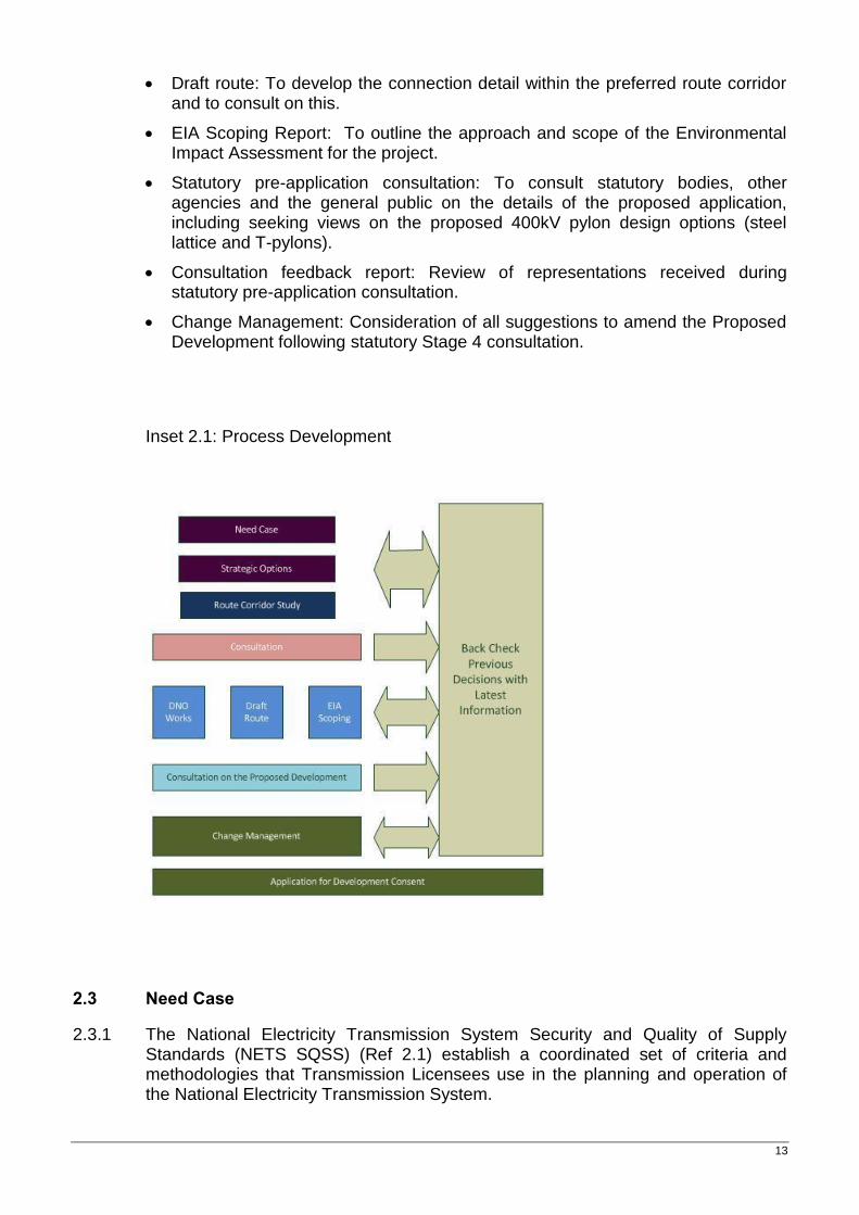
2.2.1 Development of the project is described below and illustrated in Inset 2.1. A number of the steps took place in parallel and there was an on-going back-checking process:
Need Case: To confirm the need to develop the high voltage transmission system to provide a secure connection for new power stations.
Strategic optioneering: To develop and assess strategic options that would meet the identified need, including assessment of alternative technologies and selection of an option to take forward.
Route corridor study: To take account of environmental constraints and define potential areas of land or ‘route corridors’ for the new overhead line and identify the most appropriate option to meet the need.
Initial consultation: To obtain the views of statutory bodies, other agencies and the general public on the potential route corridors.
Back-check and review of options: To take the opportunity before corridor selection to verify that the need case and review of strategic options remained valid in light of any changes in circumstances and consider representations received.
Route corridor selection: To consider which of the possible route corridors is preferred and announce the preferred corridor.
Assessment of impact of infrastructure changes on the local electricity network and development of options to ensure electricity supplies are maintained (resulting from the proposed removal of existing 132kV overhead lines and where the Proposed Development interacts with the existing local electricity network).
13
Draft route: To develop the connection detail within the preferred route corridor and to consult on this.
EIA Scoping Report: To outline the approach and scope of the Environmental Impact Assessment for the project.
Statutory pre-application consultation: To consult statutory bodies, other agencies and the general public on the details of the proposed application, including seeking views on the proposed 400kV pylon design options (steel lattice and T-pylons).
Consultation feedback report: Review of representations received during statutory pre-application consultation.
Change Management: Consideration of all suggestions to amend the Proposed Development following statutory Stage 4 consultation.
Inset 2.1: Process Development
2.3 Need Case
2.3.1 The National Electricity Transmission System Security and Quality of Supply Standards (NETS SQSS) (Ref 2.1) establish a coordinated set of criteria and methodologies that Transmission Licensees use in the planning and operation of the National Electricity Transmission System.
Hinkley Point C Connection Project – Volume 5.2.1
14
2.3.2 The existing transmission system in South West England and South Wales has adequate capacity and resilience to comply with NETS SQSS for current levels of generation and demand. However, the electricity industry is undergoing unprecedented changes in the drive towards a low-carbon economy, which is seeing major investment in low-carbon generation. These new generation projects need connections to the transmission system and in some places that means additional transmission capacity is required to continue to meet the requirements of the NETS SQSS.
2.3.3 Under the terms of its transmission licence, National Grid is obliged to make an offer of connection in response to each valid application made. In September 2007, National Grid received an application for the connection of a proposed new nuclear power station at Hinkley Point, Somerset (Hinkley Point C Power Station) to the high voltage electricity transmission system.
2.3.4 This connection, as well as others in the South West and South Wales, triggered the need for new transmission capacity in the region.
2.3.5 A detailed explanation of the need for the Proposed Development is contained in Volume 7.5 (Hinkley Point C Connection Need Case for the South West and the South Wales and Gloucestershire Regions (April 2014)).
2.3.6 The Need Case explains that, based on the contracted generation background, in the South West by 2021, new transmission capacity in excess of 4,142 MW will be required. In addition, by 2023 South Wales and Gloucestershire will require new transmission capacity of over 4,240 MW, with a requirement for additional transmission capacity to facilitate new generation connections at Seabank.
2.4 Strategic Alternatives 400kV Connection
Strategic Options - 2009
2.4.1 Having identified the need to develop the high voltage transmission system, as explained in 2.3, National Grid considered an extensive range of options to resolve the need case.
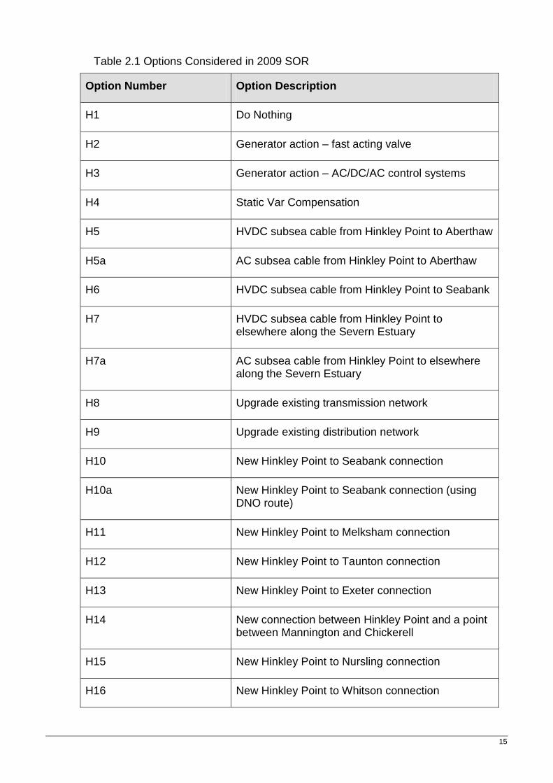
2.4.2 Initially, National Grid considered 23 alternative options at workshops involving representatives of National Grid’s specialist teams and its alliance partners who construct connections. The details of the strategic options considered are contained in a separate Strategic Options report published in December 2009 (the “2009 SOR”) (Volume 5.2.2.1, Appendix 2A).
2.4.3 Before proposing new transmission infrastructure, National Grid will seek to provide transmission capacity by upgrading or reconfiguring the existing transmission system, or the use of innovative new technologies. In addition the construction of new sub-sea and on-shore connections are also considered. The 23 options are shown in Table 2.1 below:
15
Table 2.1 Options Considered in 2009 SOR
Option Number Option Description
H1 Do Nothing
H2 Generator action – fast acting valve
H3 Generator action – AC/DC/AC control systems
H4 Static Var Compensation
H5 HVDC subsea cable from Hinkley Point to Aberthaw
H5a AC subsea cable from Hinkley Point to Aberthaw
H6 HVDC subsea cable from Hinkley Point to Seabank
H7 HVDC subsea cable from Hinkley Point to elsewhere along the Severn Estuary
H7a AC subsea cable from Hinkley Point to elsewhere along the Severn Estuary
H8 Upgrade existing transmission network
H9 Upgrade existing distribution network
H10 New Hinkley Point to Seabank connection
H10a New Hinkley Point to Seabank connection (using DNO route)
H11 New Hinkley Point to Melksham connection
H12 New Hinkley Point to Taunton connection
H13 New Hinkley Point to Exeter connection
H14 New connection between Hinkley Point and a point between Mannington and Chickerell
H15 New Hinkley Point to Nursling connection
H16 New Hinkley Point to Whitson connection
Hinkley Point C Connection Project – Volume 5.2.1
16
Option Number Option Description
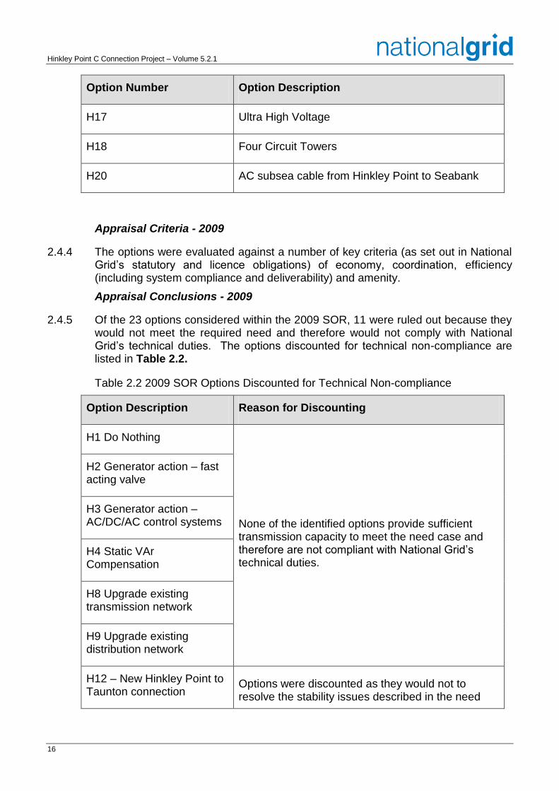
H17 Ultra High Voltage
H18 Four Circuit Towers
H20 AC subsea cable from Hinkley Point to Seabank
Appraisal Criteria - 2009
2.4.4 The options were evaluated against a number of key criteria (as set out in National Grid’s statutory and licence obligations) of economy, coordination, efficiency (including system compliance and deliverability) and amenity.
Appraisal Conclusions - 2009
2.4.5 Of the 23 options considered within the 2009 SOR, 11 were ruled out because they would not meet the required need and therefore would not comply with National Grid’s technical duties. The options discounted for technical non-compliance are listed in Table 2.2.
Table 2.2 2009 SOR Options Discounted for Technical Non-compliance
Option Description Reason for Discounting
H1 Do Nothing
None of the identified options provide sufficient transmission capacity to meet the need case and therefore are not compliant with National Grid’s technical duties.
H2 Generator action – fast acting valve
H3 Generator action – AC/DC/AC control systems
H4 Static VAr Compensation
H8 Upgrade existing transmission network
H9 Upgrade existing distribution network
H12 – New Hinkley Point to Taunton connection
Options were discounted as they would not to resolve the stability issues described in the need

17
Option Description Reason for Discounting
H13 – New Hinkley Point to Exeter connection
case and therefore are not compliant with National Grid’s technical duties.
H14 – New connection between Hinkley Point and a point between Mannington and Chickerell
H18 - Four Circuit Towers Discounted due to non-compliance as single mode failure of a pylon would result in four circuits being lost.
H19 - Uprate Hinkley Point to Bridgwater circuit to 400kV and extend to Axminster
Discounted as the option does not provide sufficient transmission capacity to meet the need case and is therefore not compliant with National Grid’s technical duties.
2.4.6 Of the 12 remaining options 8 were discounted because they would involve extremely high costs and potential technical difficulties when compared to the alternatives. The options discounted are listed in Table 2.3.
Hinkley Point C Connection Project – Volume 5.2.1
18
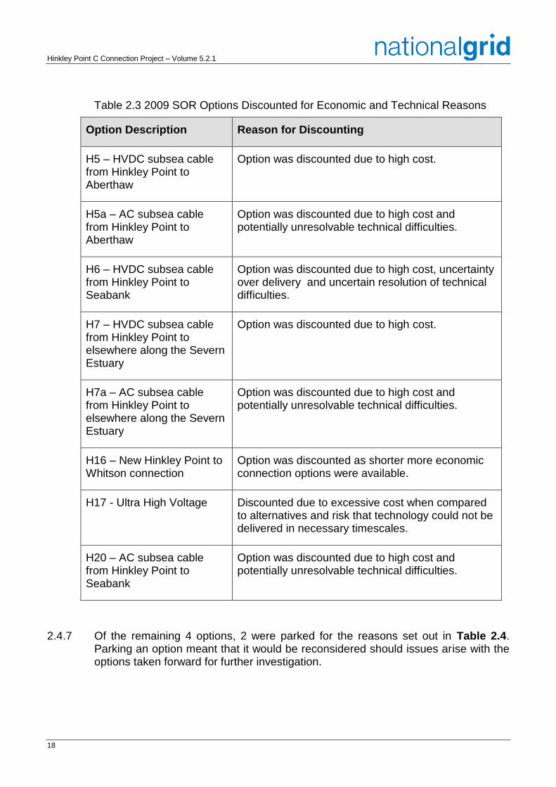
Table 2.3 2009 SOR Options Discounted for Economic and Technical Reasons
Option Description Reason for Discounting
H5 – HVDC subsea cable from Hinkley Point to Aberthaw
Option was discounted due to high cost.
H5a – AC subsea cable from Hinkley Point to Aberthaw
Option was discounted due to high cost and potentially unresolvable technical difficulties.
H6 – HVDC subsea cable from Hinkley Point to Seabank
Option was discounted due to high cost, uncertainty over delivery and uncertain resolution of technical difficulties.
H7 – HVDC subsea cable from Hinkley Point to elsewhere along the Severn Estuary
Option was discounted due to high cost.
H7a – AC subsea cable from Hinkley Point to elsewhere along the Severn Estuary
Option was discounted due to high cost and potentially unresolvable technical difficulties.
H16 – New Hinkley Point to Whitson connection
Option was discounted as shorter more economic connection options were available.
H17 - Ultra High Voltage Discounted due to excessive cost when compared to alternatives and risk that technology could not be delivered in necessary timescales.
H20 – AC subsea cable from Hinkley Point to Seabank
Option was discounted due to high cost and potentially unresolvable technical difficulties.
2.4.7 Of the remaining 4 options, 2 were parked for the reasons set out in Table 2.4. Parking an option meant that it would be reconsidered should issues arise with the options taken forward for further investigation.
19
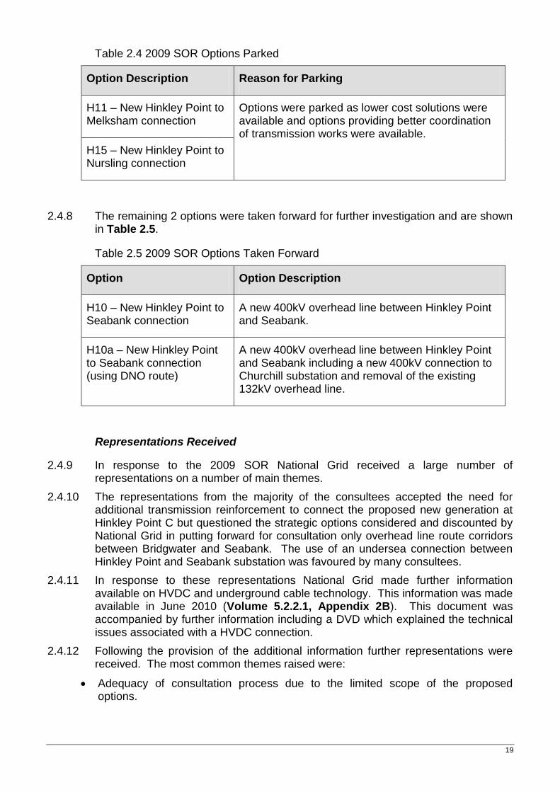
Table 2.4 2009 SOR Options Parked
Option Description Reason for Parking
H11 – New Hinkley Point to Melksham connection
Options were parked as lower cost solutions were available and options providing better coordination of transmission works were available.
H15 – New Hinkley Point to Nursling connection
2.4.8 The remaining 2 options were taken forward for further investigation and are shown in Table 2.5.
Table 2.5 2009 SOR Options Taken Forward
Option Option Description
H10 – New Hinkley Point to Seabank connection
A new 400kV overhead line between Hinkley Point and Seabank.
H10a – New Hinkley Point to Seabank connection (using DNO route)
A new 400kV overhead line between Hinkley Point and Seabank including a new 400kV connection to Churchill substation and removal of the existing 132kV overhead line.
Representations Received
2.4.9 In response to the 2009 SOR National Grid received a large number of representations on a number of main themes.
2.4.10 The representations from the majority of the consultees accepted the need for additional transmission reinforcement to connect the proposed new generation at Hinkley Point C but questioned the strategic options considered and discounted by National Grid in putting forward for consultation only overhead line route corridors between Bridgwater and Seabank. The use of an undersea connection between Hinkley Point and Seabank substation was favoured by many consultees.
2.4.11 In response to these representations National Grid made further information available on HVDC and underground cable technology. This information was made available in June 2010 (Volume 5.2.2.1, Appendix 2B). This document was accompanied by further information including a DVD which explained the technical issues associated with a HVDC connection.
2.4.12 Following the provision of the additional information further representations were received. The most common themes raised were:
Adequacy of consultation process due to the limited scope of the proposed options.
Hinkley Point C Connection Project – Volume 5.2.1
20
Respondents favour the use of alternative technologies such as subsea HVDC cables and undergrounding power lines.
Request for further consideration to and information and consultation on subsea and undergrounding options, including costs.
The effect on the visual amenity of the area from 46m pylons.
The effect of the proposals on tourism and the local economy.
2.4.13 In response to representations made concerning its consideration of alternative connection options and the scope of its options appraisal, National Grid undertook a review and updated information on alternative connection options. This information is documented in the further Strategic Optioneering Report (August 2011) (the “2011 SOR”) (Volume 5.2.2.1, Appendix 2C) that:
re-assessed the capital costs of the principal options;
considered other technologies put forward by consultees, including Gas-Insulated-Lines;
considered the lifetime costs of connection options;
considered more fully the high level environmental effects of each option; and
considered the high level socio-economic effects of each option.
Strategic Options - 2011
2.4.14 The 2011 SOR assessed five potential connections listed below and shown in Inset 2.2:
PC1: Hinkley – Aberthaw (subsea).
PC2: Bridgwater – Melksham.
PC3: Bridgwater – Nursling.
PC4: Bridgwater – Seabank (onshore).
PC5: Hinkley Point – Seabank (subsea).
21
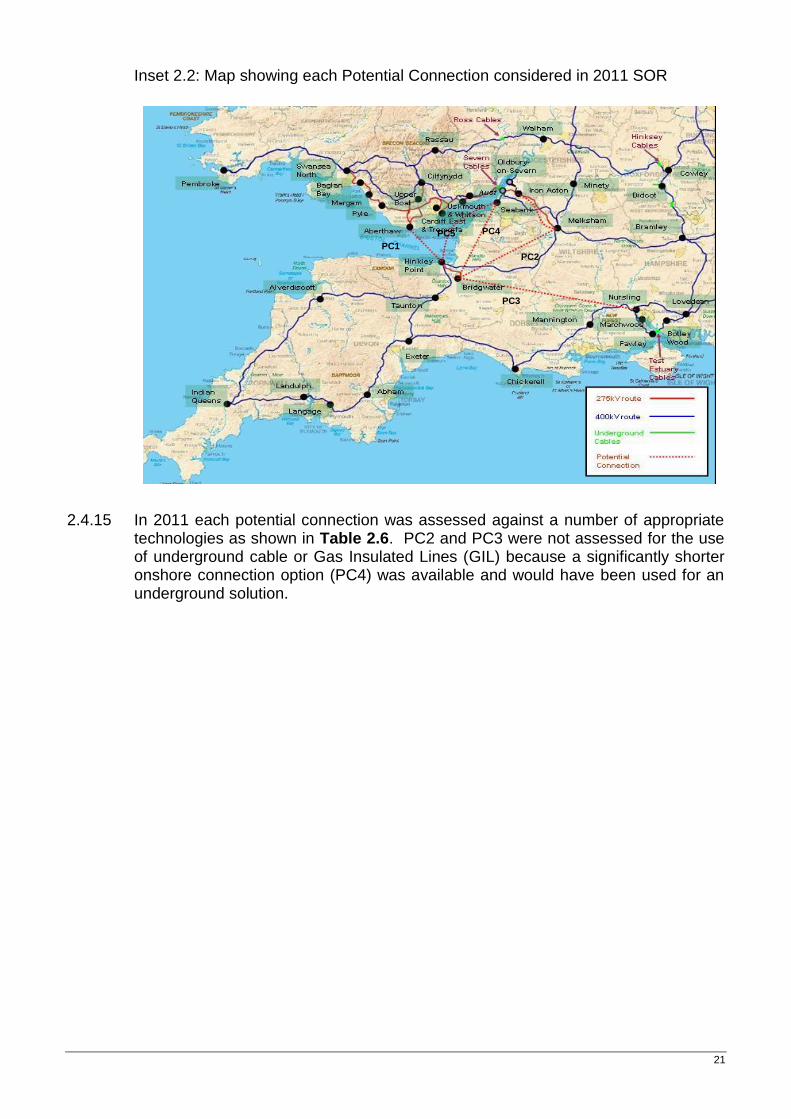
Inset 2.2: Map showing each Potential Connection considered in 2011 SOR
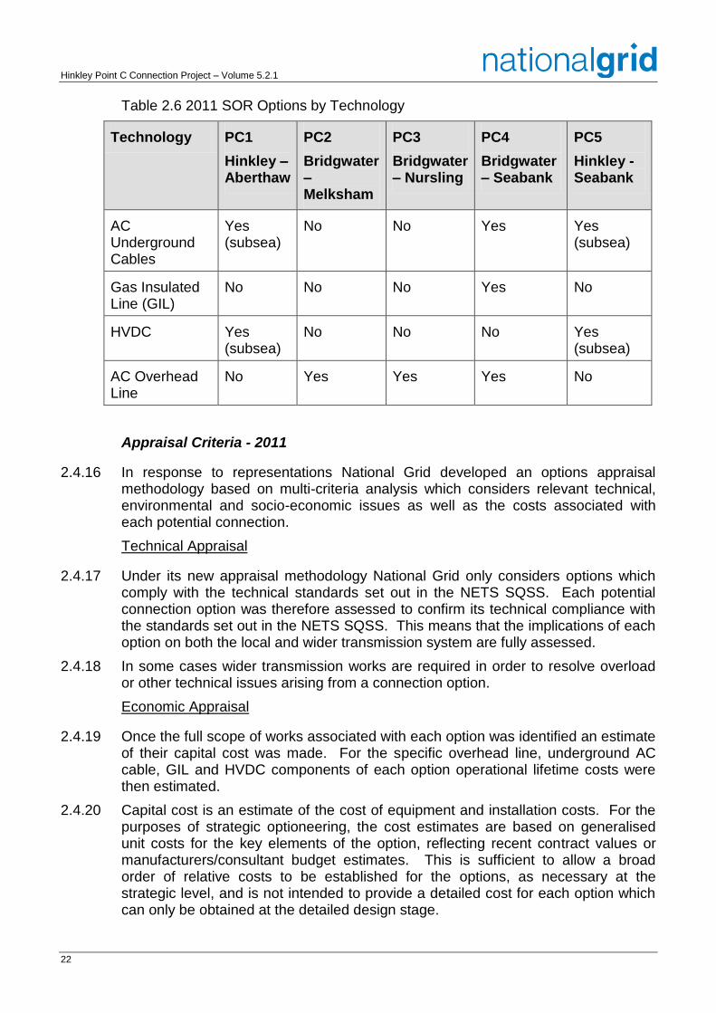
2.4.15 In 2011 each potential connection was assessed against a number of appropriate technologies as shown in Table 2.6. PC2 and PC3 were not assessed for the use of underground cable or Gas Insulated Lines (GIL) because a significantly shorter onshore connection option (PC4) was available and would have been used for an underground solution.
PC1 PC2
PC3
PC4 PC5
Hinkley Point C Connection Project – Volume 5.2.1
22
Table 2.6 2011 SOR Options by Technology
Technology PC1
Hinkley – Aberthaw
PC2
Bridgwater – Melksham
PC3
Bridgwater – Nursling
PC4
Bridgwater – Seabank
PC5
Hinkley - Seabank
AC Underground Cables
Yes (subsea)
No No Yes Yes (subsea)
Gas Insulated Line (GIL)
No No No Yes No
HVDC Yes (subsea)
No No No Yes (subsea)
AC Overhead Line
No Yes Yes Yes No
Appraisal Criteria - 2011
2.4.16 In response to representations National Grid developed an options appraisal methodology based on multi-criteria analysis which considers relevant technical, environmental and socio-economic issues as well as the costs associated with each potential connection.
Technical Appraisal
2.4.17 Under its new appraisal methodology National Grid only considers options which comply with the technical standards set out in the NETS SQSS. Each potential connection option was therefore assessed to confirm its technical compliance with the standards set out in the NETS SQSS. This means that the implications of each option on both the local and wider transmission system are fully assessed.
2.4.18 In some cases wider transmission works are required in order to resolve overload or other technical issues arising from a connection option.
Economic Appraisal
2.4.19 Once the full scope of works associated with each option was identified an estimate of their capital cost was made. For the specific overhead line, underground AC cable, GIL and HVDC components of each option operational lifetime costs were then estimated.
2.4.20 Capital cost is an estimate of the cost of equipment and installation costs. For the purposes of strategic optioneering, the cost estimates are based on generalised unit costs for the key elements of the option, reflecting recent contract values or manufacturers/consultant budget estimates. This is sufficient to allow a broad order of relative costs to be established for the options, as necessary at the strategic level, and is not intended to provide a detailed cost for each option which can only be obtained at the detailed design stage.
23
2.4.21 The lifetime cost is an estimate of the transmission losses and maintenance costs for the specific overhead line, underground AC cable (including shunt reactors), GIL or HVDC converter and cable elements of the connection options over a 40 year lifetime.
Environmental Appraisal
2.4.22 The environmental appraisal for each of the Potential Connections considered environmental constraints of international and national importance.
2.4.23 A high level planning policy and socio-economic appraisal was also undertaken to identify the main areas of economic importance in policy terms. The status of particular areas in employment terms is largely reflected in Development Plans and any supporting Economic Development Strategies, prepared by local authorities or regional bodies. In considering the planning policy context the 2011 SOR looked at:
LDF Core Strategies;
saved policies in Local Plans/Unitary Plans;
saved policies in Minerals Local Plans (prepared at County level), and
Minerals Core Strategies (prepared at County level, where available).
2.4.24 The planning policy areas relevant to socio-economic issues where development implications might affect/be affected by potential connection Options were:
spatial settlement policies;
employment policies, including tourism;
recreation/leisure policies including green infrastructure;
areas of current/potential mineral workings, and
other significant development proposals with impacts relevant to strategic options.
2.4.25 For tourism (including recreation) amenity, there is no accredited designation comparable for example with habitat or biodiversity designations. In its absence, assessment of the importance of tourism (including recreation) activity and the potential for it to be affected by a Potential Connection Option examined:
the number and proportion of visitor-related businesses in the economy;
concentrations of such businesses and their scale;
examination of tourism expenditure data, and
identification of amenities, businesses or attractions which attract large numbers of visitors to the area.
Hinkley Point C Connection Project – Volume 5.2.1
24
2.4.26 An analysis of the Agricultural Land Classification survey data was undertaken. This identifies the significance of high quality agricultural land in each Potential Connection Option area, where it is located, and as a proportion of all agricultural land in the area.
Appraisal Conclusions - 2011
2.4.27 The economic review showed that AC overhead line technology would be the most economic of the options. AC underground cables and GIL are less economic but it was acknowledged that either could be used in combination which AC overhead lines if there was a need to mitigate the potential impacts of overhead lines on sensitive locations. HVDC generally becomes more economic where transmission takes place over long distances; which does not apply in the current case. It would be the most expensive option. Lifetime costs which were also calculated are not sufficiently significant to influence a decision.
2.4.28 An evaluation of socio-economic factors considered the potential impacts of each connection option on the main areas of economic importance in planning policy terms and on the tourism and agricultural business sectors. It concluded that it was not possible to discriminate between options on the basis of the socio-economic evaluation.
2.4.29 The significant cost of the sub-sea options Hinkley-Aberthaw (PC1) (AC £1,560m & HVDC £1,602m) and Hinkley-Seabank (PC5) (AC £1,443m & HVDC £1,169m), together with connection routes through the Severn Estuary, which would require further assessment to establish the potential for any significant adverse effects on the Ramsar site, Special Protection Area, Special Area of Conservation and Site of Special Scientific Interest, lead to the conclusion that these options should only be pursued if there were no other practicable options.
2.4.30 The additional works, greater length and amenity impact, capital and lifetime costs of potential connections between Bridgwater and Melksham (£815m) or Nursling (£1,094m) compared with those of Bridgwater to Seabank (£612.9m) meant that, of the overhead line options, Bridgwater to Seabank would be preferred for further development. The two other technology options considered for a Bridgwater to Seabank connection would both be more expensive than an overhead line connection, GIL would be £775m more expensive and an AC underground cable £990m more expensive. While both would offer benefits in terms of landscape and views over an equivalent length of overhead line, the construction of underground/GIL connections would be more invasive than for an overhead line and would have a greater scale of effect on sites important for their ecology or archaeology.
2.4.31 The conclusion of the 2011 SOR was that the option of constructing an overhead transmission line between Bridgwater and Seabank would best meet National Grid's technical, economic and environmental obligations and should remain the preferred option to take forward for further investigation, taking National Grid's statutory obligations and its licence standards into account. It was recognised that sections of the proposed connection may be placed underground and that these and other mitigation measures would be investigated in the next stage of the project.
25
Representations Received
2.4.32 Throughout the life of the project representations have been received covering a number of common themes:
the connection should be sub-sea, and
the connection should be placed underground and should consider utilising GIL technology.
2.4.33 Each theme is considered in turn below.
The Connection should be Sub-sea
2.4.34 Representations have been made at each stage of the project requesting that a sub-sea connection should be selected in favour of the proposed on-shore development.
2.4.35 National Grid is bound by its statutory duties as set out in Section 9 of the Electricity Act (1989) to develop and maintain an efficient, coordinated and economical system of electricity transmission, and to have regard to amenity and minimise impacts. The analysis of alternative options presented in the 2011 SOR concluded that an overhead line connection between Bridgwater and Seabank best met the balance of factors that it must consider.
2.4.36 National Grid has continued to back-check its 2011 analysis and is of the view that no new environmental or socio-economic factors have arisen that would affect the conclusions of the 2011 SOR. However, following changes to the connection dates of new generators in the region the scope of works associated with each option have changed and the unit costs of each technology have increased since 2011.
2.4.37 National Grid has produced an Update Report (Volume 7.4), which outlines the change in the scope of works and updates the cost of each option to reflect 2014 unit prices. The cost of the sub-sea options Hinkley-Aberthaw (PC1) (AC £1,417m & HVDC £1,519m) and Hinkley-Seabank (PC5) (AC £1,295m & HVDC £1,074m), are much greater than those of Bridgwater to Seabank (PC4) (£329m).
2.4.38 National Grid considers that the significant difference in costs between a sub-sea and on-shore connection (£729m at minimum), support the conclusions of the 2011 SOR that PC4 should be progressed.
2.4.39 In addition, the Update Report documents the costs of the proposed scheme in order to compare the overall costs against those of the alternative options.
2.4.40 Since the 2011 SOR National Grid has developed further the detailed design of option PC4 which now includes a substantial amount of mitigation by proposing to underground significant sections of the 400kV connection and existing WPD 132kV overhead lines in the region. These additional works result in a new scheme capital cost for the proposed scheme (PC4P) of £678m.
2.4.41 It is important to note that neither subsea option (PC1 & PC5) have been subject to similar detailed design and as such these alternatives remain high level design options. It is highly likely that were these options progressed to detailed design that additional costs would be required to address mitigation issues that would arise in each case.
Hinkley Point C Connection Project – Volume 5.2.1
26
2.4.42 However, even comparing the more detailed design option PC4P (total capital cost £678m) with a high level PC5 Hinkley Point – Seabank subsea HVDC alternative (total capital cost of £1,074m) the capital cost difference between the options remains significant at £396m.
2.4.43 Also comparing the circuit lifetime cost for PC4P (circuit lifetime cost £538m) and option PC5 (circuit lifetime cost £1,271m), shows a difference in cost of £733m.
2.4.44 The proposed scheme provides the most robust connection with 6.38 GW (6,380 MW) of capacity. As an Alternating Current (AC) solution, the circuit naturally responds to system needs instantaneously when electrical faults occur. The circuit capacity can accommodate significant further generator connections. The AC connection also allows for direct electrical connections to be made to the circuit in the future should new forms of generation along the route of the connection seek a transmission connection.
2.4.45 Option PC5 HVDC provides a connection solution with a 4 GW (4,000 MW) capacity and therefore has 2,380 MW less capacity than the AC alternative. Further, the HVDC solution does not respond naturally to system conditions but requires control mechanisms to adjust power flows. This provides significant, but not insurmountable, risks to managing the power system requirements, including reversing power flow in very short timescales. Although HVDC technology continues to develop quickly there is no operational experience of the technology reversing in the timescales required for secure transmission system operation.
2.4.46 The cost estimates for the proposed scheme (PC4P) are higher than those considered as part of the comparative assessment of options documented in the 2011 SOR. The cost estimate increase is related to the mitigation works that have been identified as part of the development of the scheme. National Grid does not consider that the increase to the estimated costs of the proposed scheme (PC4P) is of an extent that would suggest a subsea option should be progressed.
2.4.47 PC4P is therefore confirmed to be National Grid’s preferred option and the option which best meets National Grid’s statutory duties.
The Connection should be Placed Fully Underground and should consider Utilising Gas Insulated Line Technology
2.4.48 Representations have been made at each stage of the project requesting that an underground connection should be selected in favour of the proposed development. Since 2010 representations have been made that the connection should be placed underground using Gas Insulated Line (GIL) technology.
2.4.49 As with the subsea cable option, National Grid is bound by its statutory duties as set out in Section 9 of the Electricity Act (1989) to develop and maintain an efficient, coordinated and economical system of electricity transmission, and to have regard to amenity and minimise impacts. The analysis of alternative options presented in the 2011 SOR concluded that an overhead line connection between Bridgwater and Seabank best met the balance of factors that it must consider.
2.4.50 National Grid continued to back-check its 2011 analysis and considered that no new environmental or socio-economic factors have arisen that affected the conclusions of the 2011 SOR.
27
2.4.51 However, following changes to the connection dates of new generators in the region the scope of works associated with each option changed and the unit costs of each technology have increased since 2011.
2.4.52 National Grid therefore produced an Update Report (Volume 7.4), that confirmed that the cost of the Bridgwater to Seabank (£262m), overhead line option, was significantly lower than both underground cables and GIL. The other technology options considered for a Bridgwater to Seabank connection would both be more expensive than an overhead line connection, GIL (£1,128m) would be £866m more expensive and an AC underground cable (£1,292m) would be £1,030m more expensive.
2.4.53 Based on this further comparison of potential connection options using the cost estimate information presented in this Update Report, an overhead line connection between Bridgwater and Seabank was the lowest cost option. National Grid concluded that the changes identified to contractual requirements and to cost estimates did not significantly impact on the rationale for the conclusions of the 2011 SOR that an overhead line connection between Bridgwater and Seabank should be progressed.
2.4.54 In addition, the costs of the proposed scheme were produced in order to compare the overall costs did with both a fully underground and GIL solution.
2.4.55 Since the 2011 SOR National Grid has developed further the detailed design of option PC4 which now includes a substantial amount of mitigation by proposing to underground significant sections of the 400kV connection and existing WPD 132kV overhead lines in the region. These additional works result in a new overall capital cost for the proposed scheme (PC4P) of £553m.
2.4.56 It is important to note that neither a fully underground or GIL connection have been subject to similar detailed design and as such these alternatives remain high level design options. It is highly likely that were these options progressed to detailed design that additional costs would be required to address mitigation issues that would arise in each case.
2.4.57 However, even comparing the more detailed design option PC4P (total capital cost £553m) with a high level Bridgwater – Seabank underground alternative (total capital cost of £1,292m) the capital cost difference between the options was £739m. Similarly for a GIL connection (£1,128m) the capital cost difference between the options was £575m.
2.4.58 The cost estimates for PC4P are higher than those considered as part of the comparative assessment of options. The cost estimate increase is related to the mitigation works that have been identified as part of the development of the scheme. National Grid does not consider that the increase to the estimated costs of PC4P option is of an extent that would suggest any other option should be progressed.
2.4.59 PC4P was therefore confirmed to be National Grid’s preferred option.
2.5 Route Corridor Selection – 400kV Connection
Route Corridor Study
2.5.1 Having identified that the preferred connection should be based on a new 400kV overhead line between Bridgwater and Seabank, a route corridor study (RCS) was
Hinkley Point C Connection Project – Volume 5.2.1
28
undertaken to identify potential route corridors between these locations (the RCS is presented in full at Volume 5.2.2.2, Appendix 2D).
2.5.2 The RCS considered National Grid’s guidance notes on the routeing and siting of infrastructure including its Schedule 9 Statement, the Holford Rules and its undergrounding policy to identify areas that route corridors should seek to avoid and those on which corridors should minimise effects. In addition to identifying constraints in the form of specific features designated for protection, landscape and landform were also considered.
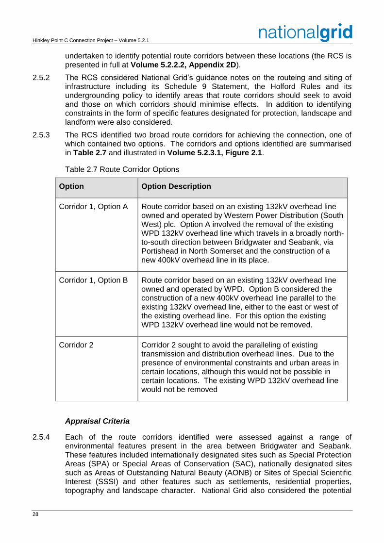
2.5.3 The RCS identified two broad route corridors for achieving the connection, one of which contained two options. The corridors and options identified are summarised in Table 2.7 and illustrated in Volume 5.2.3.1, Figure 2.1.
Table 2.7 Route Corridor Options
Option Option Description
Corridor 1, Option A Route corridor based on an existing 132kV overhead line owned and operated by Western Power Distribution (South West) plc. Option A involved the removal of the existing WPD 132kV overhead line which travels in a broadly north-to-south direction between Bridgwater and Seabank, via Portishead in North Somerset and the construction of a new 400kV overhead line in its place.
Corridor 1, Option B Route corridor based on an existing 132kV overhead line owned and operated by WPD. Option B considered the construction of a new 400kV overhead line parallel to the existing 132kV overhead line, either to the east or west of the existing overhead line. For this option the existing WPD 132kV overhead line would not be removed.
Corridor 2 Corridor 2 sought to avoid the paralleling of existing transmission and distribution overhead lines. Due to the presence of environmental constraints and urban areas in certain locations, although this would not be possible in certain locations. The existing WPD 132kV overhead line would not be removed
Appraisal Criteria
2.5.4 Each of the route corridors identified were assessed against a range of environmental features present in the area between Bridgwater and Seabank. These features included internationally designated sites such as Special Protection Areas (SPA) or Special Areas of Conservation (SAC), nationally designated sites such as Areas of Outstanding Natural Beauty (AONB) or Sites of Special Scientific Interest (SSSI) and other features such as settlements, residential properties, topography and landscape character. National Grid also considered the potential
29
effects of the corridors on development plan allocations, in particular those for housing developments. The corridors were then compared to identify the corridor that would best avoid or minimise effects on the feature of interest (the ‘least environmentally constrained corridor’).
Appraisal Conclusions
2.5.5 The RCS concluded that Corridor 1 Option A was clearly the least environmentally constrained corridor as it would use the route of an existing 132kV overhead line and would not result in any additional overhead lines in the landscape. This corridor would also minimise effects on the Mendip Hills AONB, SPAs, SACs, Ramsar sites, National Nature Reserves, Scheduled Monuments and settlements. It was considered that the relatively wide corridor assumed for much of the route would enable a variety of route alignments to be identified which would minimise the scale of change and effects on the environment.
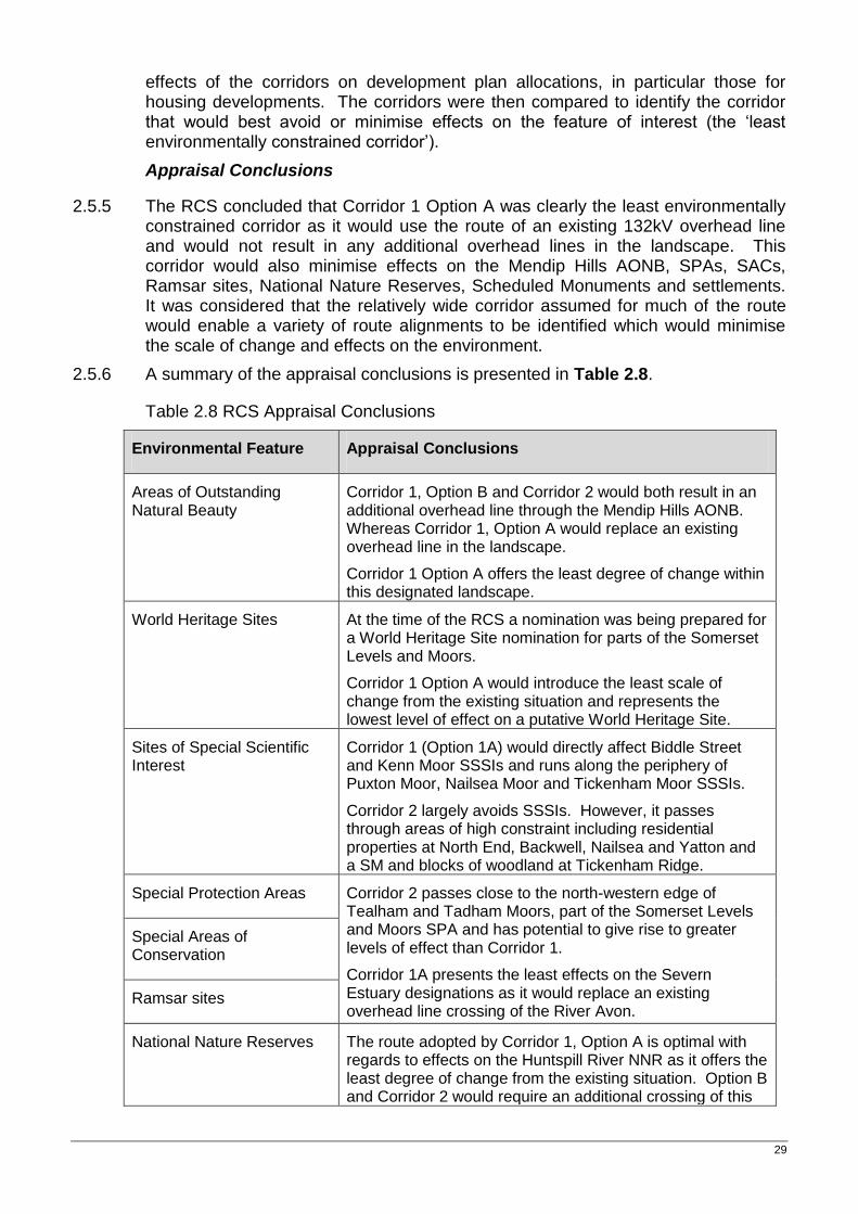
2.5.6 A summary of the appraisal conclusions is presented in Table 2.8.
Table 2.8 RCS Appraisal Conclusions
Environmental Feature Appraisal Conclusions
Areas of Outstanding Natural Beauty
Corridor 1, Option B and Corridor 2 would both result in an additional overhead line through the Mendip Hills AONB. Whereas Corridor 1, Option A would replace an existing overhead line in the landscape.
Corridor 1 Option A offers the least degree of change within this designated landscape.
World Heritage Sites At the time of the RCS a nomination was being prepared for a World Heritage Site nomination for parts of the Somerset Levels and Moors.
Corridor 1 Option A would introduce the least scale of change from the existing situation and represents the lowest level of effect on a putative World Heritage Site.
Sites of Special Scientific Interest
Corridor 1 (Option 1A) would directly affect Biddle Street and Kenn Moor SSSIs and runs along the periphery of Puxton Moor, Nailsea Moor and Tickenham Moor SSSIs.
Corridor 2 largely avoids SSSIs. However, it passes through areas of high constraint including residential properties at North End, Backwell, Nailsea and Yatton and a SM and blocks of woodland at Tickenham Ridge.
Special Protection Areas Corridor 2 passes close to the north-western edge of Tealham and Tadham Moors, part of the Somerset Levels and Moors SPA and has potential to give rise to greater levels of effect than Corridor 1.
Corridor 1A presents the least effects on the Severn Estuary designations as it would replace an existing overhead line crossing of the River Avon.
Special Areas of Conservation
Ramsar sites
National Nature Reserves The route adopted by Corridor 1, Option A is optimal with regards to effects on the Huntspill River NNR as it offers the least degree of change from the existing situation. Option B and Corridor 2 would require an additional crossing of this
Hinkley Point C Connection Project – Volume 5.2.1
30
Environmental Feature Appraisal Conclusions
designated site.
Scheduled Monuments The existing overhead line oversails Mere Bank Scheduled Monument and is present in its setting however paralleling (Option B and Corridor 2) would lead to greater effects on the designated site than Corridor 1 Option A.
Corridor 1 Option B has the greatest potential to introduce effects on settings of other Scheduled Monuments.
Listed Buildings There is no substantial difference between the corridors with regard to listed buildings.
Conservation areas There is no substantial difference between the corridors with regard to Conservation Areas.
Registered parks and gardens
Corridor 2 passes within 700m of Tyntesfield Registered Park and Garden. As a result Corridor 1 would be preferred with respect to effects on this feature.
Woodlands Corridor 2 offers the least potential to avoid woodland by alignment (particularly around Knowle and Tickenham Ridge)
Settlements Corridor 1 Option A maximises the potential for
minimisation of adverse amenity effects on properties
Isolated properties Corridor 1 runs in closest proximity to scattered dwellings (particularly Option B).
Development plan allocations for housing
None of the route corridors would have any direct effects upon any areas identified in development plans for housing
Minerals sites None of the route corridors would have any direct effects upon identified active mineral extraction sites.
Topography There is no discernable difference between the corridors in terms of topography.
Landscape character The corridors run through areas of similar landscape character and are not differentiated by the character areas affected.
Corridor 1A is considered distinctly preferred in terms of landscape as it would minimise the scale of change in the landscape through the replacement of an existing lower voltage overhead line.
Representations Received
2.5.7 To help inform the selection of a preferred route corridor for the connection, National Grid undertook a period of non-statutory pre-application consultation to
31
invite the views of local people, communities and other interested parties living in the vicinity of the proposed works (Stage 1 Consultation).
2.5.8 The majority of representations from consultees questioned the strategic options considered and discounted by National Grid in putting forward for consultation only overhead line route corridors between Bridgwater and Seabank. However, a number of comments were received regarding the feasibility of alternatives to the two route corridors put forward for consultation. These included:
could the overhead line use a route parallel to the M5 motorway corridor;
could the route avoid the Mendip Hills AONB;
National Grid should switch between corridors in parts of the route;
could the overhead line follow the existing railway line; and
could the overhead line follow the coastline.
M5 Route
2.5.9 The feasibility of a route close and parallel to the M5 motorway was considered as part of National Grid’s RCS. In accordance with National Grid’s guidance on the siting and routeing of infrastructure and a supplementary note to the Holford Rules (guidelines on overhead line routeing), route corridors were chosen which seek to avoid residential areas as far as possible on grounds of general amenity. They also sought, as far as possible, to keep high voltage overhead lines away from smaller lines, distribution poles and other masts, wires and cables in order to avoid the creation of a ‘wirescape’. A route that followed the west of the M5 motorway was not considered feasible because of the proximity of large towns at Burnham-on-sea, Weston-super-Mare and Clevedon.
2.5.10 A route to the east of the M5 motorway was investigated and one of National Grid’s initial route corridors (Corridor 2) followed this route within and north of the Mendip Hills wherever possible. However, there are significant obstacles that do not make it feasible to closely follow the eastern side of the M5 motorway all the way, including:
the villages of East Huntspill, Hackness and Walrow;
the low voltage overhead lines to the east of Brent Knoll and the villages of Rooks Bridge and Edingworth;
the village of Kenn;
the village of Tickenham;
the split level M5 motorway and large blocks of woodland (including ancient woodland) to the north of Tickenham; and
the village of Portbury.
2.5.11 The feasibility of a route parallel to the M5 continued to be raised in subsequent rounds of consultations and, in response to the representations received, National Grid undertook further analysis in to the feasibility of a route close and parallel to the M5 motorway to the south of the Mendip Hills AONB. Although a route was
Hinkley Point C Connection Project – Volume 5.2.1
32
identified, it was less direct than the preferred route corridor and involved multiple changes in direction (and as a result large angle pylons) to avoid residential properties and constraints in close proximity to the motorway. This route would also have resulted in greater adverse effects on the setting of the Mendip Hills AONB and Brent Knoll Scheduled Monument than a route within the preferred route corridor and would result in greater effects on landscape as it is less direct and would introduce a greater scale of change than would occur as compared to routeing a new 400kV overhead line along the route of the existing 132kV line. As a result this route was not considered to offer any environmental or technical benefits over a route based on the preferred route corridor and was therefore not taken forward. This analysis was documented in the ‘M5 Routeing Study’ (Volume 5.2.2.2, Appendix 2E).
Route Avoiding the AONB
2.5.12 The feasibility of a route which avoided the Mendip Hills AONB was considered as part of initial optioneering studies and the RCS. It was concluded that it would not be feasible to avoid the Mendip Hills AONB in any reasonably direct connection route between Bridgwater and Seabank. To the west of the AONB potential routes are constrained by areas of ancient woodland and the settlement of Weston-super-Mare, and to the east, the AONB designation extends for approximately 22km.
Mix and Match
2.5.13 The RCS considered the possibility of mixing and matching the route corridors to achieve an optimum route and identified that at the southern end of the route at Puriton Ridge and in the area of Puxton Moor and Biddle Street SSSI there may be the possibility to use a combination of route corridors. This was considered further as part of the selection of a preferred route corridor for the connection.
Corridor Following the Railway
2.5.14 Whilst in principle an overhead line route could run parallel to a railway line, in the area between Bridgwater and Seabank the railway line runs north from Bridgwater through the settlements of Weston-super-Mare, Yatton and Nailsea before travelling in to the city of Bristol. Following this route would bring the overhead line close to a number of large centres of population and is unlikely to feasible without oversailing large numbers of residential properties. Following this route would also not achieve a connection into Seabank substation.
Corridor Following the Coastline
2.5.15 Whilst technically it would be possible to route an overhead line along the coastline, the route would pass in close proximity to the large towns of Burnham-on-Sea, Weston-super-Mare, Clevedon and Portishead and a number of national and international environmental designations such as SAC, SPA, Ramsar and SSSI. As a result this route was considered more constrained than the corridors identified.
Selection of Preferred Route Corridor
2.5.16 In response to the representations received during the Stage 1 Consultation, National Grid undertook an assessment to consider the relative merits of the two route corridors against a range of factors. This assessment, (Volume 5.2.2.3,
33
Appendix 2F) also considered opportunities to mix and match the corridors to achieve the optimum route for the connection.
2.5.17 This assessment informed the selection of a preferred route corridor for the project and was informed by:
the requirements of the Planning Act 2008 and associated Regulations;
National Grid’s statutory duties;
planning policy; and
National Grid’s own policies.
Appraisal Criteria
2.5.18 Both of the route corridors identified through the RCS were assessed against the following factors.
National Grid’s statutory duties;
compliance with planning policy;
compliance with National Grid’s policies;
consultation representations;
landscape and visual impacts;
effects on the historic environment;
effects on biodiversity and geological conservation;
effects on land use and socio-economic factors;
engineering – deliverability;
effects on civil and military aviation and defence interests; and
effects on flood risk and climate change resilience.
Appraisal Conclusions
2.5.19 The appraisal concluded that Corridor 1 Option A, see Volume 5.2.3.1, Figure 2.2, should form the basis for the connection as it would result in the least impact on the Mendip Hills AONB, would result in the least degree of change within the landscape, would comply most closely with guidance provided by the Holford Rules and would result in less effect on landscape and views, the historic environment and ecological receptors.
2.5.20 A summary of the appraisal is presented in Table 2.9.
Hinkley Point C Connection Project – Volume 5.2.1
34
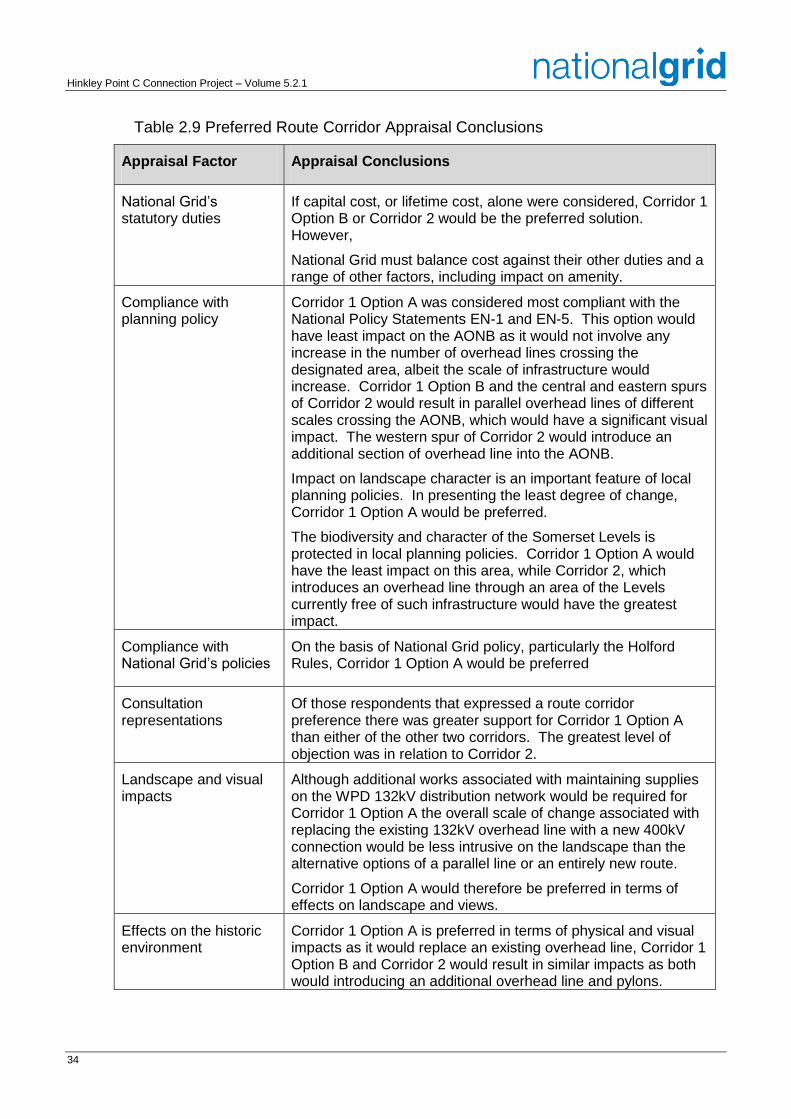
Table 2.9 Preferred Route Corridor Appraisal Conclusions
Appraisal Factor Appraisal Conclusions
National Grid’s statutory duties
If capital cost, or lifetime cost, alone were considered, Corridor 1 Option B or Corridor 2 would be the preferred solution. However,
National Grid must balance cost against their other duties and a range of other factors, including impact on amenity.
Compliance with planning policy
Corridor 1 Option A was considered most compliant with the National Policy Statements EN-1 and EN-5. This option would have least impact on the AONB as it would not involve any increase in the number of overhead lines crossing the designated area, albeit the scale of infrastructure would increase. Corridor 1 Option B and the central and eastern spurs of Corridor 2 would result in parallel overhead lines of different scales crossing the AONB, which would have a significant visual impact. The western spur of Corridor 2 would introduce an additional section of overhead line into the AONB.
Impact on landscape character is an important feature of local planning policies. In presenting the least degree of change, Corridor 1 Option A would be preferred.
The biodiversity and character of the Somerset Levels is protected in local planning policies. Corridor 1 Option A would have the least impact on this area, while Corridor 2, which introduces an overhead line through an area of the Levels currently free of such infrastructure would have the greatest impact.
Compliance with National Grid’s policies
On the basis of National Grid policy, particularly the Holford Rules, Corridor 1 Option A would be preferred
Consultation representations
Of those respondents that expressed a route corridor preference there was greater support for Corridor 1 Option A than either of the other two corridors. The greatest level of objection was in relation to Corridor 2.
Landscape and visual impacts
Although additional works associated with maintaining supplies on the WPD 132kV distribution network would be required for Corridor 1 Option A the overall scale of change associated with replacing the existing 132kV overhead line with a new 400kV connection would be less intrusive on the landscape than the alternative options of a parallel line or an entirely new route.
Corridor 1 Option A would therefore be preferred in terms of effects on landscape and views.
Effects on the historic environment
Corridor 1 Option A is preferred in terms of physical and visual impacts as it would replace an existing overhead line, Corridor 1 Option B and Corridor 2 would result in similar impacts as both would introducing an additional overhead line and pylons.
35
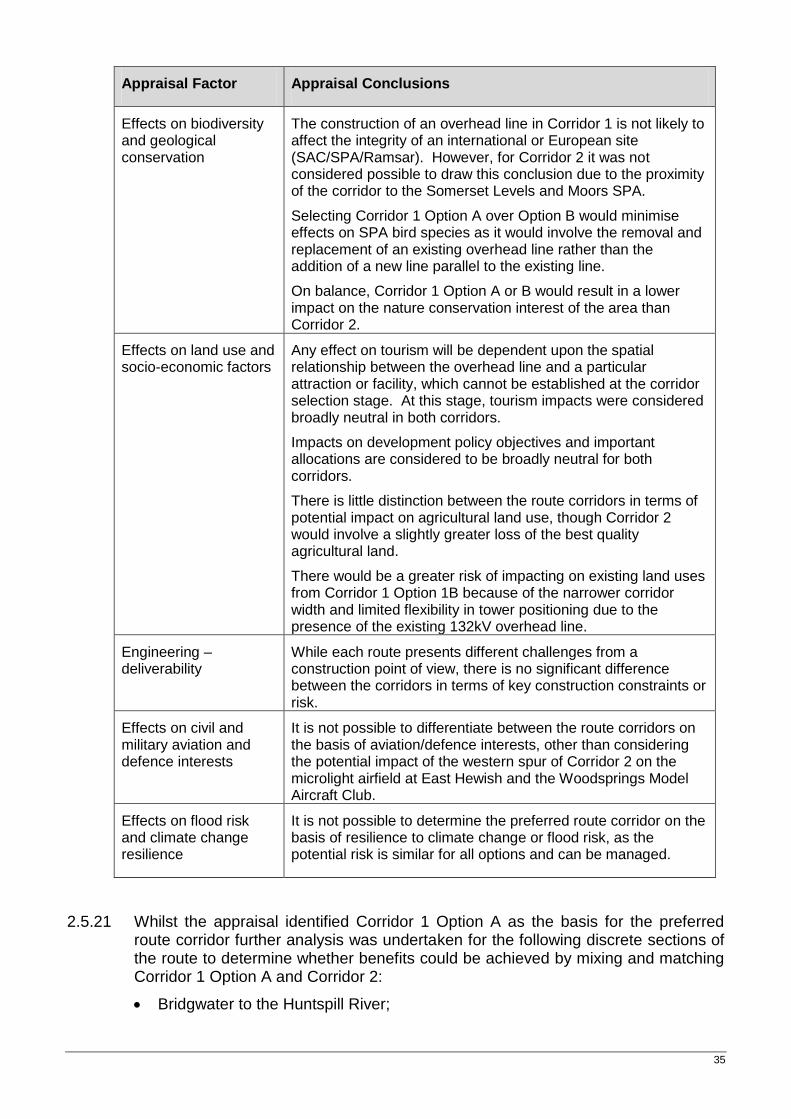
Appraisal Factor Appraisal Conclusions
Effects on biodiversity and geological conservation
The construction of an overhead line in Corridor 1 is not likely to affect the integrity of an international or European site (SAC/SPA/Ramsar). However, for Corridor 2 it was not considered possible to draw this conclusion due to the proximity of the corridor to the Somerset Levels and Moors SPA.
Selecting Corridor 1 Option A over Option B would minimise effects on SPA bird species as it would involve the removal and replacement of an existing overhead line rather than the addition of a new line parallel to the existing line.
On balance, Corridor 1 Option A or B would result in a lower impact on the nature conservation interest of the area than Corridor 2.
Effects on land use and socio-economic factors
Any effect on tourism will be dependent upon the spatial relationship between the overhead line and a particular attraction or facility, which cannot be established at the corridor selection stage. At this stage, tourism impacts were considered broadly neutral in both corridors.
Impacts on development policy objectives and important allocations are considered to be broadly neutral for both corridors.
There is little distinction between the route corridors in terms of potential impact on agricultural land use, though Corridor 2 would involve a slightly greater loss of the best quality agricultural land.
There would be a greater risk of impacting on existing land uses from Corridor 1 Option 1B because of the narrower corridor width and limited flexibility in tower positioning due to the presence of the existing 132kV overhead line.
Engineering – deliverability
While each route presents different challenges from a construction point of view, there is no significant difference between the corridors in terms of key construction constraints or risk.
Effects on civil and military aviation and defence interests
It is not possible to differentiate between the route corridors on the basis of aviation/defence interests, other than considering the potential impact of the western spur of Corridor 2 on the microlight airfield at East Hewish and the Woodsprings Model Aircraft Club.
Effects on flood risk and climate change resilience
It is not possible to determine the preferred route corridor on the basis of resilience to climate change or flood risk, as the potential risk is similar for all options and can be managed.
2.5.21 Whilst the appraisal identified Corridor 1 Option A as the basis for the preferred route corridor further analysis was undertaken for the following discrete sections of the route to determine whether benefits could be achieved by mixing and matching Corridor 1 Option A and Corridor 2:
Bridgwater to the Huntspill River;
Hinkley Point C Connection Project – Volume 5.2.1
36
Huntspill River to Webbington;
Webbington to Yatton;
Yatton to Portishead; and
Portishead to Seabank.
2.5.22 Between Bridgwater and the Huntspill River National Grid identified that a mix and match solution should be adopted. Corridor 2 was preferred between Horsey and Woolavington as it would allow the identification of a detailed route which maximised the distance from properties in this area and utilised land with a more gradual sloping gradient which may offer greater opportunities for backgrounding than in Corridor 1. Between Woolavington and the Huntspill River, Corridor 1 Option A was preferred as Corridor 2 would run closer to the northern residential edge of Woolavington than the existing overhead line and could have a direct effect on Middle Moor Water Park.
2.5.23 Between the Huntspill River and Webbington National Grid identified that there would be no benefits in mixing and matching the corridors and as a result Corridor 1 Option A should be preferred, as it replaces an existing line which already has an impact on the area through which it passes. Corridor 2 would be almost 3km longer than Corridor 1 in this section of the route which would increase the number of pylons and the cost of construction. On Corridor 2, the scale of change to the landscape would be greater as it would involve introducing a new line into a relatively undeveloped area of the Somerset Levels and Moors and closer to the villages of Blackford, Chapel Allerton, Stone Allerton and Badgworth.
2.5.24 Between Webbington and Yatton National Grid also identified that there would be no benefits in mixing and matching the corridors and as a result Corridor 1 Option A was preferred. The appraisal recognised that to the north of the Mendip Hills AONB it would be possible to select either the central or eastern spurs of Corridor 2 for a new connection, removing the 132kV infrastructure on Corridor 1 Option A. However, it was considered that there would be little advantage in doing this as the eastern spur of Corridor 2 would have to cross more of the Biddle Street SSSI than Corridor 1 Option A and would pass much closer to the Cheddar Valley Walk LNR and the village of Yatton. The central spur of Corridor 2 would introduce overhead lines into the area west of Puxton which would add to the impact of the existing 132kV line to Weston, at variance with Holford Rule 6.
2.5.25 As a result of public consultation representations, a review was also undertaken of the potential impacts associated with the western spur of Corridor 2 which runs adjacent to the M5 motorway between Banwell and Yatton. Several consultees suggested that a route corridor following the M5 motorway would be preferable and the western spur to Corridor 2 would provide this approach. However, it would bring overhead lines close to the proposed development areas at Locking on the eastern side of Weston-super-Mare and due to the limited corridor width available at Banwell the route would pass in close proximity to Banwell Caves SSSI, which is part of the North Somerset and Mendip Bats SAC. An overhead line in this corridor would also be more visible in views from and to the Mendip Hills AONB as it would travel across higher ground rather than utilizing the low lying land of the Lox Yeo Valley.
37
2.5.26 Between Yatton and Portishead Corridor 1 Option A was preferred between Yatton and the top of Tickenham Ridge as it would result in the replacement of an existing line, albeit at larger scale, rather than the construction of an additional line. This issue was considered particularly important in the context of Nailsea. Corridor 2 would rise to follow a valley alongside the Bristol-Weston railway and would introduce new electricity infrastructure into an area where none exists at present. An overhead line would be prominent in views from the southern and eastern edges of Nailsea.
2.5.27 From the top of Tickenham Ridge to Portishead, National Grid identified that a mix and match solution should be adopted. Corridor 1 Option A passed very close to the edge of Clapton-in-Gordano and the recently developed Port Marine residential area south of Portishead Dock. The overhead line between Churchill and Portishead, followed by Corridor 2, maintained a degree of separation between it and residential properties and was therefore, preferred for this section of the route.
2.5.28 Between Portishead and Seabank, the presence of a continuous band of development which extends from Avonmouth to Bristol constrains routes and means that there was effectively only one route corridor. It was concluded that Corridor 1 Option A should be adopted between Portishead and Avonmouth Substation and that between Avonmouth Substation and Seabank Substation, Corridor 2 should be adopted as WPD had indicated that it needed to retain the 132kV connection between Avonmouth and Seabank substations to maintain supplies on its network.
2.6 Detailed Route Selection – 400kV Connection
Identifying the Draft Route
2.6.1 During 2012 and 2013, the preferred route corridor was separated into a number of Study Areas (later renamed ‘Sections’) within which a range of overhead line routes were developed, see Volume 5.2.3.1, Figure 2.3. An underground cable route was also developed within each of the Sections and in accordance with paragraph 2.8.9 of the National Policy Statement EN-5 a comparison was made to determine whether the benefits from the non-overhead line alternative would clearly outweigh any additional economic, social and environmental impacts and the technical difficulties were surmountable. This was documented in the Connection Options Report (2012) (Volume 5.2.2.4, Appendix 2G).
2.6.2 The starting point for the identification of routes was to consider potential alignments which lay within the limits of the preferred route corridor as this had been defined taking account of a range of environmental factors and criteria and using guidance provided by the Holford Rules. However, it was recognised that situations may arise along the route where environmental constraints suggested that a more acceptable alignment for an option for a possible overhead line route might extend outside the defined corridor limits.
2.6.3 As the preferred route corridor had been defined for an overhead line connection, National Grid recognised that there was no strong driver for the underground cable route to remain within the limits of the preferred route corridor. However, the underground cables route would need to interface with existing overhead lines at Bridgwater Tee and the Huntspill split and would need to connect in to the proposed substation at Sandford and the existing substation at Seabank.
Hinkley Point C Connection Project – Volume 5.2.1
38
Potential Alignments
2.6.4 The application of the Holford Rules resulted in three overhead line routes (one of which comprised two potential alternatives in one section of the route) and a single underground cable route (with sub-options in a number of areas). The three alternative overhead line alignments and single underground cable alignment considered in detail and consulted on are illustrated at Volume 5.2.3.2, Figure 2.4.1 - 2.4.8 and described below.
Green, Blue and Red Overhead Line Routes
2.6.5 The Green Route was designed to follow the existing 132kV F Route as closely as possible. Since this overhead line was constructed, properties and development had encroached in a number of areas such that appropriate electrical safety clearances could not be achieved for a 400kV overhead line following the same alignment. This resulted in deviations to the alignment at Mark Causeway, Nailsea and Portishead.
2.6.6 The Blue Route and the Red Route represented different ways of applying the Holford Rules by, for example, avoiding sites of special scientific interest or maximising distances from residential or other sensitive properties. In Study Areas B, F and G a variation to the Blue Route was developed to provide a more direct alignment through part of these areas, this was referred to as the Alternative Blue Route.
2.6.7 Fewer routeing options were available at the northern and southern ends of the route. In Study Area A, the 132kV F Route overhead line is not present in the route corridor. As a result only the Blue and Red Routes were considered. In Study Area G, the 132kV G Route would be retained between Avonmouth and Seabank substations and potential routes are constrained by built development. As a result only the Blue and Red Routes were considered north of the River Avon.
Underground Cable Route
2.6.8 An underground cable route was developed to avoid as far as possible areas of environmental constraints, including developed areas, woodland, SSSI and County Wildlife Sites, Scheduled Monuments, and areas of archaeological potential. This was to minimise disturbance to such features and limit environmental effects. For the majority of the route a single option was developed (the Orange Route) however minor variations to this route were considered at Tarnock, at the crossing of the River Yeo west of Congresbury and in the area west of Portbury. In the Avonmouth area (Study Area G) two potential route options were identified which would be of similar length but would have different implications in terms of effects on land use. The Orange Route would involve running cables beneath some of the areas highways whereas the Brown Route would run beneath the dock estate and across largely open land.
Other Routes considered but Discounted
2.6.9 Within each of the Study Areas consideration was also given to a number of other overhead line and underground cable options however it was determined that these should not be taken forward. A summary of the main options considered and the reasons they were discounted is provided by Study Area below.
39
Study Area A
Overhead Line Options
2.6.10 Consideration was given to an overhead line route directly through the centre of the corridor which would minimise the changes in direction, see Volume 5.2.3.2, Figure 2.4.1. However such an option would involve oversailing a property, woodland loss on the slopes of Puriton Ridge and would bring the line closer to Knowle Park. To avoid these constraints the Blue and Red Routes in the southern half of the Study Area were focussed in the western part of the corridor.
2.6.11 At the northern end of Study Area A consideration was given to an overhead line route in the east or west of the corridor. However this would involve oversailing properties to the south of Woolavington Road. For this reason the Blue and Red Routes were routed closer to the centre of the corridor to maximise distance to properties.
Underground Cable Options
2.6.12 Although other underground cable routes were considered in Study Area A all of the routes were constrained by the topography of the land, blocks of woodland (including Home Covert, Chisland Covert and Eleven Acre Covert) and properties to the north of the A39 (including Knowle Hall) and along Woolavington Road.
Study Area B
Overhead Line Routes
2.6.13 To the north of Woolavington, consideration was given to an alignment following the route of the 132kV F Route overhead line, see Volume 5.2.3.2, Figure 2.4.2. However, this would introduce an angle pylon close to the edge of the settlement, result in the line passing very close to a fishing lake and would not allow any overhead line pylons on the existing Hinkley to Melksham overhead line to be removed. As a result, both the Blue and Red Routes passed to the east of the 132kV F Route overhead line.
2.6.14 Through the settlement of Mark, consideration was given to an alignment which followed the route of the 132kV F Route overhead line as closely as possible. This would involve oversailing a caravan park and passing in close proximity to a number of properties and a school. Due to these constraints, all potential routes utilised a larger gap in the settlement crossing Mark Causeway to the east of Harp Road.
2.6.15 To the north of Mark, consideration was given to a route through the centre of the corridor to the west of the 132kV F Route overhead line and east of the Red Route. This would bring the overhead line closer to properties and would require the alignment to pass through gaps between properties along Vole Road as this option offered no benefits over any of the routes identified this option was not taken forward for further assessment.
2.6.16 At Rooks Bridge consideration was given to a route to the east of the 132kV F Route overhead line which utilised the eastern extent of the corridor. However this option would involve oversailing properties which extend along the A38 between Rooks Bridge and Tarnock. An overhead line route that followed the underground cable route was also considered but would require a number of sharp changes of direction to the north and south of Tarnock. As these routes were either unfeasible or offered no benefits over the routes identified these options were not taken
Hinkley Point C Connection Project – Volume 5.2.1
40
forward and all potential routes crossed the A38 in the vicinity of the 132kV F Route.
2.6.17 To the north of Rooks Bridge routeing in the east of the corridor would bring an overhead line closer to the settlement of Biddisham whilst routeing further west in the corridor would introduce additional changes in direction in the route of the overhead line to the north of Rooks Bridge. These changes in direction and the larger angle pylons required to make these changes would be particularly prominent in views from the AONB.
Underground Cable Options
2.6.18 Although other underground cable routes were considered in Study Area B all of the routes identified were longer, less direct and involved a greater number of changes in direction than the Orange Route. These routes would not only result in greater environmental effects due to their increased length but would also incur higher costs.
Study Area C
Overhead Line Routes
2.6.19 The Green Blue and Red Routes all enter the Mendip Hills AONB through the only natural break in the hills and closely follow the alignment of the 132kV F Route overhead line along the valley of the Lox Yeo River, see Volume 5.2.3.2, Figure 2.4.3. Alternative routes to the east or west of the existing overhead line would need to utilise higher ground within the AONB which would make them more prominent in the landscape.
Underground Cable Options
2.6.20 Alternative underground cable routes to the route identified would be less direct and would need to utilise higher ground within the AONB, leading to greater environmental effects and higher costs.
Study Area D
Overhead Line Routes
2.6.21 In the southern half of the Study Area between Puxton and North End, consideration was given to a straight alignment starting to the east of the Red Route and west of the Blue and Green Routes and crossing the Red Route to the north of Wemberham Lane, see Volume 5.2.3.2, Figure 2.4.4. This option would involve oversailing a residential caravan park, a farm and Acorn Carp Fishery. As the routes identified avoided these constraints there were not considered to be any benefits in pursuing his option further.
2.6.22 The Green Route adopts the 132kV F Route for the majority of this Study Area with the exception of a short section from the south western edge of Nailsea to Stone-Edge Batch. Continuing to follow the 132kV F Route in this area was discounted because the existing overhead line closely parallels the 132kV W Route and passes in close proximity to a large number of properties along the edge of Nailsea. Routeing in the extreme west of the corridor (beyond the Blue Route) was also considered but would bring the proposed overhead line closer to properties in Kenn and Tickenham and would require a number of angle pylons and changes of direction to divert the route back towards Stone-Edge Batch.
41
2.6.23 Alternative alignments to the Blue, Green and Red Routes at Stone-Edge Batch were not considered feasible due to the proximity of residential properties, a public house and the existing 132kV overhead lines.
Underground Cable Routes
2.6.24 To the south of Yatton, consideration was given to an underground cable route which avoided the Biddle Street Site of Special Scientific Interest (SSSI). Due to settlement along the A370 and the requirement to directionally drill under both the A370 and the River Yeo there would be insufficient land available to achieve the working width required for an underground cable route in this area.
2.6.25 To the north of Yatton, consideration was given to an underground cable route which avoided the Nailsea, Kenn and Tickenham Moors SSSI. Routes to the south of Kenn Moor SSSI and east of Nailsea and Tickenham Moors SSSIs were considered but would require the underground cables to pass through the streets in the settlements of Yatton and Nailsea and would need a number of sharp changes of direction. Routes to the west and north of the SSSIs would be significantly longer and less direct than the route identified, would still need to pass through part of the designated site and would be constrained by properties in Kenn and Tickenham.
Study Area E
Overhead Line and Underground Cable Routes
2.6.26 Whilst other overhead line and underground cable routes on Tickenham Ridge could be achieved they would be constrained by the topography of the land and would result in greater effects on blocks of woodland and ancient woodland (including Chummock Wood, Moggs Wood and Priors Wood) properties on Cadbury Camp Lane and Noah’s Ark Zoo than the routes identified, see Volume 5.2.3.2, Figure 2.4.5. As these routes were either unfeasible or offered no benefits over the routes identified these options were not taken forward.
Study Area F
Overhead Line Routes
2.6.27 Between the M5 motorway and Portishead, consideration was given to an alignment which utilised the full width of the route corridor to the east of the Blue, Green and Red Routes, see Volume 5.2.3.2, Figure 2.4.6. This route would require an oblique crossing of the M5 motorway and would bring the overhead line closer to properties on the western edge of Sheepway. As this option provided no environmental benefit over the options identified it was not taken forward.
Underground Cable Routes
2.6.28 To the north of the M5 motorway, consideration was given to a underground cable route following the route corridor and the 132kV W Route towards Portishead. This option would have restricted potential locations for cable sealing end compounds, would be longer than a route close to the M5 and would need to travel through the wetlands of the Portbury Wharf nature reserve. Both environmental effects and costs would therefore be greater and this option was therefore not taken forward.
Hinkley Point C Connection Project – Volume 5.2.1
42
Study Area G
Overhead Line Routes
2.6.29 In Avonmouth consideration was given to an alignment to the west of the Blue and Red Routes that crossed the River Avon from the Royal Portbury Dock onto the Avonmouth Docks at Nelson Point, see Volume 5.2.3.2, Figure 2.4.7. On such an alignment, the overhead line would need to oversail Avonmouth Dock which accommodates large vessels and regularly operates large travelling cranes. This would require tall pylons in addition to those required to cross the River Avon. For this reason it was considered preferable to cross the river further to the east thus avoiding the dock basins.
2.6.30 Consideration was also given to potential alignments which followed the route of the existing 132kV F Route overhead line. This option would involve oversailing numerous residential properties and a primary school and was therefore discounted.
Underground Cable Routes
2.6.31 Consideration was given to a deep cable tunnel crossing of the River Avon to both an intermediate point adjacent to the north of Avonmouth village and direct to Seabank substation. Whilst these options could technically be achieved they would be significantly more expensive than a direct buried underground cable route and would require tunnel headhouse infrastructure at both ends. As a result this option was not taken forward for further assessment.
2.6.32 Consideration was also given to an underground cable route which utilised the underside of the M5 Avonmouth Bridge and the motorway carriageway. Discussions with the Highways Agency confirmed operational constraints together with technical and safety issues would make routeing cables underneath the bridge unfeasible. It was also confirmed that due to the large swathe required for the underground cables and the requirement to access the cables in the event of a fault there would be no scope to route cables within the carriageway of the motorway.
Study Area H
2.6.33 To facilitate the connection of the Hinkley Point C nuclear power station a new 400kV substation is being established within the Hinkley Point site. This new substation requires connection to the transmission system. A study (Volume 5.2.2.5, Appendix 2H) assessed a number of technical options for connecting the new substation.
2.6.34 Three options were assessed within the study. Two of the options resulted in a total of five double circuit transmission connections while the third option only required four double circuits.
2.6.35 Option 3 was taken forward for appraisal as it minimised the amount of new infrastructure, therefore would have a lower level of environmental effect and was the most economic.
2.6.36 Three technology options were considered in the appraisal of Option 3, overhead line, underground cable and gas insulated lines. The study concluded that the additional cost of developing an underground solution rather than an overhead line
43
could not be justified as the benefits of an underground option did not outweigh the significant additional cost.
2.6.37 It was noted that effects on landscape and visual receptors would be reduced in significance due to the influence of existing power stations and overhead lines in the area. Potential impacts on land protected by ecological and historic environment designations could be minimised through careful routeing.
2.6.38 Following the selection of the preferred connection method three technically feasible overhead line alignments were identified, see Volume 5.2.3.2, Figure 2.4.8.
Appraisal Criteria
2.6.39 Each of the overhead line routes was assessed by Study Area using a range of criteria from the disciplines of environment, socio-economics and cost, using professional judgement to balance the issues and compare the effects of the routes to identify the preferred option, or combination of options. The preferred route was then compared against the underground cables route considering the following criteria as set out at paragraph 2.8.9 of the National Policy Statement EN-5 to determine whether benefits of the underground cables would “clearly outweigh any extra economic, social and environmental impacts”:
the landscape in which the proposed line will be set;
the additional costs of any undergrounding; and
the environmental and archaeological consequences of undergrounding.
2.6.40 The criteria considered as part of the appraisal were:
Environment
landscape;
visual amenity;
historic environment; and
ecology.
Socio-economic
Local economic impact.
Cost
capital cost; and
lifetime cost.
Hinkley Point C Connection Project – Volume 5.2.1
44
Appraisal Conclusions
2.6.41 The draft route is illustrated in Volume 5.2.3.3, Figure 2.5 and each Study Area appraisal is summarised below.
Study Area A
2.6.42 Within Study Area A there was little to differentiate between the Blue and Red overhead line Routes. Both routes would result in similar effects on the landscape, the historic environment, ecology and socio-economic resources. The capital and lifetime costs of the options would also be broadly similar. However, it was considered that an overhead line on the Red Route could site angle pylons to marginally reduce effects on the closest high sensitivity receptors and as a result this option was preferred in terms of visual amenity. Additionally, as the blue route had sharper changes of direction and would involve larger, more visible, angle pylons, the Red Route was considered to be more compliant with the Holford Rules.
2.6.43 Having concluded that the preferred overhead line alignment for Study Area A would be the Red Route, National Grid considered the benefits of undergrounding in the context of the landscape in which the proposed connection would be set, together with the additional cost and the environmental and archaeological consequences of undergrounding. Whilst the use of underground cables would minimise the negative effects on landscape character, views, the Scheduled Monument at Horsey and socio economic resources associated with an overhead line it would result in a greater effect on buried archaeological remains and ecological species and habitats. The underground cable option would also involve incurring capital costs over £44m higher than those of the overhead line (£4.53m). As a result, National Grid concluded that the benefits from the use of underground cables as an alternative to the preferred overhead alignment in this location, would not clearly outweigh any extra economic, social and environmental impacts and
therefore undergrounding could not be justified.
Study Area B
2.6.44 Between the southern boundary of Study Area B and the existing Hinkley Point to Melksham overhead line there was little to differentiate between the Blue and Red Routes. However, as the Blue Route would not require a change in direction and therefore a larger angle pylon in this area it was considered to be more compliant with the Holford Rules. Adopting this option would also maximise distance from Middlemoor Water Park.
2.6.45 Between the Hinkley Point to Melksham overhead line and Mark Causeway the Green Route would minimise effects on the landscape as it would adopt the route of an existing overhead line, however the large deviations required to pass through Mark Causeway would be the most pronounced of all options. The Red Route would not require major changes in direction and would maximise the separation from the residential areas of East Huntspill and Watchfield and the separation from the lower voltage line running north from Puriton. Extending this route through Mark would help to minimise the effects of an overhead line on this settlement.
2.6.46 North of Mark, the Red Route would be least compliant with Holford Rule 3 as it is the longest and would involve a number of deviations, this route would therefore
45
have a greater effect on the landscape than either of the alternatives. There would be little to differentiate between the Green Route and Alternative Blue Route as both adopt a direct route through the Somerset Levels however the Alternative Blue Route would be slightly further from the settlement of Vole and which would help to minimise effects on views from these receptors.
2.6.47 The capital and lifetime costs of the options and their ecological and socio-economic effects were not considered to be material differentiators in options selection.
2.6.48 Having concluded that the preferred overhead line alignment for Study Area B would comprise a mixture of the Blue, Red and Alternative Blue Routes, National Grid considered the benefits of undergrounding in the context of the landscape in which the proposed connection would be set, together with the additional cost and the environmental and archaeological consequences of undergrounding. Whilst the use of underground cables would minimise the negative effects on landscape character, views and socio economic resources associated with an overhead line it would result in a greater effect on buried archaeological remains and ecological species (particularly dormice and horseshoe bats) and habitats. The underground cable option would also involve incurring capital costs approximately £250m higher than those of the overhead line (£25m). As a result, National Grid concluded that the benefits from the use of underground cables as an alternative to the preferred overhead alignment in this location, would not clearly outweigh any extra economic, social and environmental impacts and therefore undergrounding could not be
justified.
Study Area C
2.6.49 Within Study Area C there was little to differentiate between the Green, Blue and Red Routes. All routes would result in similar effects on the landscape, views, the historic environment, ecology and socio-economic resources. There would be localised differences between the routes particularly with regards to effects on Scheduled Monuments (Blue or Red Route preferred) and the local landscape (Blue Route preferable). The capital and lifetime costs of the options would also be broadly similar. While all overhead route options would have negative effects on landscape, visual amenity and the historic environment in Study Area C, overall the Blue Route would have the least negative effect on each of these receptors and was therefore the preferred overhead line route.
2.6.50 Having concluded that the preferred overhead line alignment for Study Area B would be the Blue Route, National Grid considered the benefits of undergrounding in the context of the landscape in which the proposed connection would be set, together with the additional cost and the environmental and archaeological consequences of undergrounding. There would be temporary effects on the landscape during construction of the underground cables and localised negative effects at the sites of the cable sealing end compounds. However, putting the connection underground would avoid the major negative effects on the landscape and views of the AONB associated with the Blue Route. The underground cable route would have a positive effect on the settings of Listed Buildings, but overall would have a greater negative effect on heritage receptors than the Blue Route, due to its greater effects on buried archaeological remains in the Mendip Hills (an area with high potential for preserved buried archaeological remains). The Blue Route would avoid substantial impacts on ecology however the underground cable route cannot avoid impacts on trees, hedgerows, and the ditches an rhynes which
Hinkley Point C Connection Project – Volume 5.2.1
46
form field boundaries due to its wider construction swathe. Due to its status as an AONB this Study Area would be regarded as a ‘particularly sensitive location’ in the context of paragraph 2.8.2 of EN-5. National Grid concluded that whilst there would be negative effects particularly on buried archaeology and ecology during construction of the underground cables, a new 400kV overhead line within the AONB would not positively contribute to the purpose of the AONB designation (to ‘conserve and enhance natural beauty’). However, removal of the 132kV F Route and undergrounding of the 400kV would make such a contribution. As such National Grid concluded that the benefits from the use of underground cables as an alternative to an overhead line in the AONB would clearly outweigh any extra economic, social and environmental impacts and the additional costs of undergrounding could therefore be justified.
Study Area D
2.6.51 Within Study Area D there was little to differentiate between the Green, Blue and Red Routes in terms of landscape impacts, however as it closely follows the route of an existing 132kV overhead line the Green Route would result in a slightly lower scale of change in all areas except to the west of Nailsea. The Red Route would have the greatest effect on the local landscape to the south of Kingston Seymour and the Blue Route would have a the greatest effect in the north of the Study Area as it deviates furthest from the 132kV F Route introducing sharper or more changes of direction. However in the north of the Study Area both of these routes would maximise distance from the edge of Nailsea. From a landscape and views perspective the following mixture of routes was considered to be preferable:
Red Route - from the proposed 400/132kV substation to the 132kV AT Route (furthest from sensitive receptors);
Blue Route - from the 132kV AT Route to North End (further away than Green or Red Routes from sensitive receptors);
Red Route – North End to Stone-Edge Batch (further from edge of Nailsea but maintains separation from Tickenham); and
Blue Route – Stone-Edge Batch (minimises deviation while maximising distance from settlements).
2.6.52 For the majority of the Study Area there was little to differentiate between the overhead line options in terms of impacts on the historic environment. However, overall the Blue and Red Routes both would result in greater negative effects than the Green Route; this is due to their effects on the setting of the Grade I listed church at Tickenham.
2.6.53 The capital and lifetime costs of the options and their ecological and socio-economic effects were not considered to be material differentiators in options selection.
2.6.54 On balance it was therefore considered that other factors would not lead to a conclusion different from that referring to the landscape and visual perspective and that the preferred overhead alignment for Study Area D would be a combination of:
47
Red Route - from the proposed 400/132kV substation at Sandford to the 132kV AT Route;
Blue Route - from the 132kV AT Route to North End;
Red Route – North End to Stone-Edge Batch; and
Blue Route – Stone-Edge Batch.
2.6.55 Having concluded that the preferred overhead line alignment for Study Area D would comprise a mixture of the Blue and Red Routes, National Grid considered the benefits of undergrounding in the context of the landscape in which the proposed connection would be set, together with the additional cost and the environmental and archaeological consequences of undergrounding. Whilst the use of underground cables would minimise the negative effects on landscape character, views and socio economic resources associated with an overhead line it would result in a greater effect on buried archaeological remains and ecological designated sites and species. In particular, the underground cable route would affect the Biddle Street, Yatton SSSI and the Tickenham, Nailsea and Kenn Moors SSSI which would be crossed for a significant distance by the underground cables. Whilst HDD techniques could be used to cross some of the ditches, culverts or bridges would be required for some of the ditches within the SSSI and cables installation would be required within the wildlife sites that lie between the ditches. The underground cable option would also involve incurring capital costs approximately £272m higher than those of the overhead line (approximately £25m). As a result, National Grid concluded that the benefits from the use of underground cables as an alternative to the preferred overhead alignment in this location, would not clearly outweigh any extra economic, social and environmental impacts and therefore undergrounding could not be justified
Study Area E
2.6.56 Within Study Area E there was little to differentiate between the Green, Blue and Red Routes in terms of effects on views, the historic environment, ecology and socio-economic receptors. The capital and lifetime costs of the options would also be broadly similar. With regard to landscape impacts, there are also only minor differences between the overhead line options identified for Study Area E. However, the Blue Route would be marginally preferable in terms of effects on landscape as it would run obliquely across the landscape taking a less sharp change of direction on lower partly enclosed ground. On the western part of the route it also took advantage of the opportunity for backgrounding provided by the wooded slopes of the ridge to minimise its impact. The Blue Route was selected as the preferred option as it would minimise landscape impacts and was considered to most closely comply with the Holford Rules in this area.
2.6.57 Having concluded that the preferred overhead line alignment for Study Area E would comprise a mixture of the Blue and Red Routes, National Grid considered the benefits of undergrounding in the context of the landscape in which the proposed connection would be set, together with the additional cost and the environmental and archaeological consequences of undergrounding. Whilst the use of underground cables would minimise the negative effects on landscape character, views and socio economic resources associated with an overhead line in Study Area E it would result in a greater effect on buried archaeological remains
Hinkley Point C Connection Project – Volume 5.2.1
48
and ecological designated sites and species. In particular, the underground cable route would affect a larger area and six sites of archaeological sensitivity known to exist within the underground cable route’s working width. The underground cable route would also require hedgerow removal at route crossings and would result in habitat fragmentation and loss of connectivity between habitats which could have substantive impacts on species such as bats and dormouse. The underground cable option would also involve incurring capital costs approximately £76m higher than those of the overhead line (approximately £6.3m). As a result, National Grid concluded that the benefits from the use of underground cables as an alternative to the preferred overhead alignment in this location, would not clearly outweigh any extra economic, social and environmental impacts and therefore undergrounding could not be justified.
Study Area F
2.6.58 Within Study Area F all overhead line options would result in effects on landscape character, however the Alternative Blue Route (parallel to the M5 Motorway) would result in the lowest negative effects as it is shorter, more direct, minimises sharp changes in direction and contains landscape effects to the corridor of the M5 and the A369. As a result of this, and its avoidance of the Portbury Wharf Nature Reserve, this option was also considered to be most compliant with the Holford Rules. All overhead line routes would also result in negative effect on views, particularly from the settlements of Portishead and Portbury. However, the Alternative Blue Route offered the potential to have the most positive effects on views from the largest number of high sensitivity receptors. This route was also considered to minimise effects due to its shorter length and more direct route along the existing infrastructure of the M5.
2.6.59 The Alternative Blue Route was considered to result in the greatest effect on the Historic Environment, however these effects were considered to be minor due to the distance of separation of the route from the heritage assets and the presence of the intervening M5 motorway.
2.6.60 From an ecological perspective a clear preference was identified for the Alternative Blue Route as it avoids disturbance to SPA/Ramsar birds travelling between the Severn Estuary and the Portbury Wharf and also avoids the Portbury Wharf Nature Reserve. Whilst there would be little to differentiate between the routes from a socio-economic perspective, the Alternative Blue Route was considered to benefit users of the Portbury Wharf Nature Reserve by removing visual connections.
2.6.61 The Alternative Blue Route would be the least expensive option for Study Area F at £3.02m, with the Green Route being most expensive at £5.12m. Lifetime costs would also vary from £9.01m for the Alternative Blue Route to £15.26m for the Green Route.
2.6.62 The Alternative Blue Route was selected as the preferred option in Study Area F as it was the shortest and most direct route, would minimise effects on the landscape and views impacts, would minimise effects on ecological receptors including the Portbury Wharf Nature Reserve and was considered to most closely comply with the Holford Rules.
2.6.63 Having concluded that the preferred overhead line alignment for Study Area F would comprise the Alternative Blue Route, National Grid considered the benefits of
49
undergrounding in the context of the landscape in which the proposed connection would be set, together with the additional cost and the environmental and archaeological consequences of undergrounding. Whilst the use of underground cables would minimise the negative effects on landscape character, views and the setting of historic environment assets (including a Scheduled Monument and Listed Buildings) in Study Area F it would result in a greater effect on buried archaeological remains and a number of SNCI wetlands adjacent to the M5 motorway. The underground cable option would also involve incurring capital costs approximately £10m higher than those of the overhead line (approximately £3.02m) however, due to the route of the underground cables in Section F these costs would have to be looked at in conjunction with those of Study Areas E and G. As a result, National Grid concluded that the benefits from the use of underground cables as an alternative to the preferred overhead alignment in this location, would not clearly outweigh any extra economic, social and environmental impacts and therefore undergrounding could not be justified.
Study Area G
2.6.64 Within Study Area G there was little to differentiate between the routes in terms of their effects on the Historic Environment or socio-economic receptors. To the south of the River Avon, the Alternative Blue route would offer the lowest negative effects on the landscape and views as it would be more direct than other route options and would run around the southern edge of the Portbury Docks industrial area. To the north of the River Avon there would be little to differentiate between the Blue and Red Routes however, as the Blue Route would more direct and slightly further from residential receptors in Avonmouth this was considered to offer opportunities to minimise effects. To the north of the River Avon, the Blue Route was considered to result in the greatest effect on ecological receptors, particularly SPA/Ramsar bird species travelling between the Severn Estuary and the Avonmouth Sewage Works SNCI, however, this was not considered sufficient to affect the integrity of the designated sites.
2.6.65 On balance, National Grid concluded that a combination of the Alternative Blue Route to the south of the River Avon and the Blue Route north of the River Avon should be the preferred overhead line alignment as it would minimise effect on the landscape and views and would be most compliant with the Holford Rules – specifically in terms of Rule 3 (directness), Rule 7 (approaching the urban area through industrial zones where they exist) and the Supplementary Notes (avoiding routeing close to residential areas as far as possible).
2.6.66 Having concluded that the preferred overhead line alignment for Study Area G would comprise a mix of the Alternative Blue Route and the Blue Route, National Grid considered the benefits of undergrounding in the context of the landscape in which the proposed connection would be set, together with the additional cost and the environmental and archaeological consequences of undergrounding. Whilst the use of underground cables would minimise the negative effects on landscape character and views in Study Area G it would result in a greater effect on buried archaeological remains, ecological receptors and socio-economic receptors than the preferred overhead line. In particular, the underground cable route would affect two Roman receptors and four sites of archaeological sensitivity known to exist within the underground cable route’s working width. The open-cut method of construction associated with the underground cable route could result in drying-out of wet habitats along the permanent easement of the cable route which would affect SNCIs and hedgerow removal would have an adverse effect on connectivity
Hinkley Point C Connection Project – Volume 5.2.1
50
between habitats. From a socio-economic perspective, the underground cables would result in greater disruption to local socio-economic activities due to the greater construction requirements and longer construction period. The shortest of the underground cable options would also involve incurring capital costs approximately £165m higher than those of the overhead line (approximately £14.74m). As a result, National Grid concluded that the benefits from the use of underground cables as an alternative to the preferred overhead alignment in this location, would not clearly outweigh any extra economic, social and environmental impacts and therefore undergrounding could not be justified.
Study Area H
2.6.67 Within Study Area H there was little to differentiate between the options due to the localised nature of the works proposed, see Volume 5.2.3.2, Figure 2.4.8. However, overhead line route option 5 was selected as the preferred option as it best balanced potential effects on landscape, views, ecology, historic environment and socio-economics with feedback received from local stakeholders during consultation.
Preferred CSE Compound Sites
2.6.68 CSE compounds are required where overhead lines transition to underground cables. Siting studies for the necessary compounds are described below.
Bridgwater Tee CSE Compound Siting
2.6.69 Three 400kV double circuit transmission connections are required as part of the Hinkley Point C Connection Project in order to comply with the National Electricity Transmission System Security and Quality of Supply Standard (NETS SQSS). To facilitate the connection to Melksham substation the existing 400kV Hinkley to Melksham overhead line (the ZG Route) will be split at Huntspill River, north of Woolavington, and reconnected to a new section of overhead line routed south and connecting with the existing Hinkley to Bridgwater overhead line (the VQ Route) to the north of Bridgwater. To allow a crossing of electrical circuits between the proposed ZG Route diversion and the existing VQ Route a short section of underground cables and two single circuit cable sealing end (CSE) compounds are required.
2.6.70 A number of options, see Volume 5.2.3.3, Figure 2.6, for the connection point between the proposed new overhead line and the existing VQ route were considered and documented in the Environmental Review of Technical Options at Bridgwater Tee (2013) (Volume 5.2.2.5, Appendix 2I). The selection of route corridor 2 in this location and the development of an alignment across Puriton ridge to the west of Knowle Park meant that siting the connection point on Horsey level minimised the length of overhead line required and would be in line with the Holford Rules to take the most direct route.
2.6.71 Having identified that the optimal location for the CSE compounds would be to the north of Manor Farm and Horsey Deserted Medieval Village (DMV) Scheduled Monument on the Horsey Levels four technically feasible potential options were developed:
51
Option 1 – Bridgwater circuit underground and CSE compounds adjacent to the Horsey DMV);
Option 2 – Bridgwater circuit underground and cables and CSE compounds north of Horsey Medieval Settlement;
Option 3 – Melksham circuit underground with one CSE compound adjacent to Horsey Medieval Settlement and one to the north of Horsey DMV; and
Option 4 – Melksham circuit underground and CSE compounds north of Horsey DMV.
Option 1
2.6.72 Option 1 would involve the construction of two CSE compounds immediately north of the existing VQ Route overhead line. Two replacement terminal pylons would be required and would be constructed adjacent to existing pylons on the ZG Route overhead line.
2.6.73 The northern circuit of the overhead line would be connected to the CSE compounds via downleads. The CSE compounds would be connected by approximately 350m of underground cables.
Option 2
2.6.74 Option 2 would involve the construction of two CSE compounds over 200m north of the existing VQ Route overhead line. This option would also require the removal of a short section of the existing ZG Route overhead line and the construction of a replacement section of overhead line on a realigned route to the north of the existing overhead line. Three replacement pylons would be required two of which would be sited adjacent to existing pylons on the ZG Route and one of which would be approximately 200m north of the pylon it replaces (pylon VQ44).
2.6.75 The northern circuit of the overhead line would be connected to the CSE compounds via downleads. The CSE compounds would be connected by approximately 300m of underground cables which would cross a number of watercourses in the area.
Option 3
2.6.76 Option 3 would involve the construction of two CSE compounds, one immediately adjacent to Horsey DMV south of the existing ZG Route overhead line and one to the north of the existing VQ Route overhead line. This option would only require the construction of one replacement pylon which would be sited immediately adjacent to the pylon it replaces on the ZG Route and would retain the ZG Route on its current alignment.
2.6.77 The southern circuit of the overhead line would be connected to the CSE compound via downleads. The CSE compound to the south of the ZG Route would then be connected to the compound to the north of the ZG Route by approximately 400m of underground cables which would cross a number of watercourses.
Option 4
2.6.78 Option 4 would involve the construction of two CSE compounds north of the existing ZG Route overhead line. One CSE compound would be sited to the south
Hinkley Point C Connection Project – Volume 5.2.1
52
of Withy Pool whilst the second would be sited a considerable distance north of the existing ZG Route overhead line close to Bath Road Rhyne. This option would be similar to Option B in that it would involve removal of a short section of the existing ZG Route overhead line and the construction of a replacement section of overhead line on a realigned route to the north of the existing overhead line. Like Option 2 this option would also require the construction of three replacement pylons, two of which would be sited adjacent to existing pylons on the ZG Route and one of which would be approximately 200m north of the pylon it replaces (pylon VQ44).
2.6.79 The southern circuit of the overhead line would be connected to the CSE compound via downleads. The CSE compound to the south of the realigned ZG Route would then be connected to the CSE compound close to Bath Road Rhyne by approximately 400m of underground cables which would cross a number of watercourses.
Reasons for the Selection of the Preferred CSE Compound Site
2.6.80 A CSE compound on Option 1 was considered preferable to Options 2, 3 and 4 as it would not require significant diversions to the existing VQ Route and would contain negative effects resulting from the proposed CSE compounds on the local landscape. The location of the CSE compounds adjacent to existing electrical infrastructure which forms part of baseline conditions would also minimise effects on the landscape and views and would take advantage of existing screening and backgrounding provided by trees and hedges in the local area.
2.6.81 Option 1 would require fewer crossings of watercourses by the underground cables than the alternative options and would avoid construction works within 50-250m (the intermediate terrestrial habitat) of a number of potential great crested newt breeding ponds. Due to their greater number of watercourse crossings Options 2, 3 and 4 would also result in greater impacts on ditch habitats which are potentially suitable for both otter and water vole.
2.6.82 Whilst Option 1 would result in slightly greater negative effects on archaeological remains associated with, and therefore of equivalent sensitivity to, Horsey DMV Scheduled Monument these effects were not considered sufficiently significant so as to make Option 1 unfeasible. However it was recognised that additional mitigation measures should be considered to reduce any adverse effects on the Horsey and Crook DMVs.
Mendip Hills CSE Compound Siting
2.6.83 Having concluded that 400kV underground cables should form the basis of the connection in the nationally designated landscape of the Mendip Hills AONB (Study Area C), National Grid considered potential sites to the north and south of the AONB for a cable sealing end (CSE) compound to facilitate the transition between the overhead line and underground cables. This is documented in the CSE Siting Study (2012) (Volume 5.2.2.5, Appendix 2J).
2.6.84 The assessment of environmental and planning feasibility was informed by:
National Grid guidance on the siting and routeing of infrastructure;
National Policy Statements (NPS);
National Planning Policy Framework (NPPF);
53
the adopted development plan allocations for the Study Area and emerging Local Development Framework;
environmental designations in the Study Area; and
other environmental and planning related matters that affect siting such as landscape character, flood risk, proximity to settlements etc.
South of the AONB
2.6.85 To the south of the AONB three potential CSE sites were identified, see Volume 5.2.3.3, Figure 2.7.1. These areas were large enough to accommodate a CSE compound and associated overhead line infrastructure in a number of positions or orientations and were referred to as:
Area A – land to the north of the River Axe;
Area B – land adjacent to the M5 motorway south of the River Axe;
Area C – land to the north of Rooks Bridge.
Area A – Land to the North of the River Axe
2.6.86 This site covers a broad area of farmland to the east of the M5 motorway which extends north from the River Axe to the boundary of AONB. The area lies in Flood Zone 3a where there is a high probability of flooding and contains newly planted trees in the centre and along the western boundary which provide a visual and acoustic screen to the motorway.
Area B - Land Adjacent to the M5 Motorway South of the River Axe
2.6.87 This site is the proposed CSE compound site south of the AONB submitted for development consent. It lies approximately 1km south of the AONB boundary and comprises farmland to the south of the River Axe immediately east of the M5 motorway. The site lies in Flood Zone 3a where there is a high probability of flooding. The northern boundary of the site is formed by the Hams Lane road bridge, which together with a number of mature trees to the north and west of the site provide it with a sense of enclosure and help screen it from the adjacent motorway.
Area C – Land to the North of Rooks Bridge
2.6.88 This site comprises farmland to the north of the A38 and the settlements of Rooks Bridge and Tarnock. The area lies approximately 2km south of the Mendip Hills AONB, at its closest point and is in Flood Zone 3a where there is a high probability of flooding. The site is relatively open but is bordered by hedgerows which contain some trees.
Reasons for the Selection of the Preferred Site South of the AONB
2.6.89 A CSE compound within Area B was considered preferable to one in Areas A and C primarily due to effects on the Mendip Hills AONB and its distance from residential properties and settlements. Area B is further away from the AONB than Area A and has a greater sense of enclosure and screening (provided by the Hams
Hinkley Point C Connection Project – Volume 5.2.1
54
Lane bridge and trees along the northern and western boundaries) than either Area A or Area C which would be more visible in open farmland. Siting the CSE compound in the north western corner of Area B would maximise the benefits of the screening provided by the road bridge and vegetation.
2.6.90 With respect to proximity to settlement and individual properties, Area A lies 50m south of a property along Webbington Road and 150m west of another property off Kennel Lane. It is also within 250m of properties at Crab Hole and 300m from the settlement of Loxton. Area C is within 400m of the settlements of Biddisham and Rooks Bridge. Area B is the most distant from properties and the north western corner in particular is screened in the majority of views by raised landform and vegetation.
2.6.91 Area B is further south of the AONB than Area A and as a result would result in increased costs associated with the additional length of underground cables proposed. However, it was considered that a CSE compound within Area A would be more prominent in views to and from the AONB and would result in greater adverse effects on its setting and the purposes of the AONB designation.
North of the AONB
2.6.92 To the north of the AONB two potential CSE sites were identified, see Volume 5.2.3.3, Figure 2.4.7.2.
2.6.93 These areas were large enough to accommodate a CSE compound and associated overhead line infrastructure in a number of positions or orientations and were referred to as:
Area D – Haulage Yard to the south of the A368 at Sandford;
Area E – Land to the West of Nye Road (Preferred Area of Search for 400/132kV GSP Substation).
Area D - Haulage Yard to the South of the A368 at Sandford
2.6.94 This site comprises previously developed land to the south of the A368 immediately adjacent to the AONB. The site is predominantly hardstanding currently in use as a haulage yard and is bordered to the west by Towerhead Brook and east by a residential property. Land to the rear of the haulage yard is undeveloped and contains a number of mature trees along the boundaries which provide the area with a sense of enclosure. The area is in Flood Zone 1 where there is a low probability of flooding.
Area E - Land to the West of Nye Road
2.6.95 This site comprises the proposed site for a 400/132kV substation required as part of the Proposed Development. Whilst cable sealing ends would be required, a separate compound would not be needed in this location as the underground cables could connect directly in to the substation. The site lies to the north of the settlement of Sandford and comprises pasture fields bounded by clipped hedges and scattered mature trees. The area is in Flood Zone 1 where there is a low probability of flooding but lies close to the boundaries of Flood Zones 2 and 3.
55
Reasons for the Selection of the Preferred Site North of the AONB
2.6.96 The connection of the underground cables directly into the substation within Area E was considered preferable to a separate compound in Area D primarily because it would focus development within one geographical area and would remove the requirement to develop two separate sites a short distance apart linked by between 750m and 1km of overhead line.
2.6.97 A CSE compound in Area E would also be preferable to one in Area D with respect to effects on views from the AONB and effects on residential properties. Area E lies further from the AONB boundary and benefits from screening provided by existing vegetation and natural variations in landform. Although parts of Area D comprise previously developed land, the site lies immediately adjacent to the AONB boundary and together with the overhead line that would be required from this site to the proposed 400/132kV substation would be highly visible from receptors within the AONB. A CSE compound within Area E would also be distinctly preferred to one within Area D with respect to proximity to settlement and individual properties. Area D lies within 20m of a residential property thought to be associated with the haulage yard and within 50m of a number of properties on the edge of the settlement of Sandford to the south of the A368.
Representations Received
2.6.98 To help inform the development of the proposed application, National Grid undertook a period of non-statutory pre-application consultation on the draft route (including the proposed CSE compound locations to the north and south of the AONB) to invite the views of local people, communities and other interested parties living in the vicinity of the proposed works.
2.6.99 In their responses, consultees continued to question the strategic options considered and discounted by National Grid. However, a number of comments were received regarding the feasibility of alternative routes for the overhead line or alternative sites for the CSE compounds. Representations were also received regarding the use of underground cables across entire Study Areas or in localised sections of the route. Each of the suggested changes to the route of the overhead line and the siting of the CSE compounds was assessed against using a range of criteria from the disciplines of environment, planning, design and engineering and cost, using professional judgement to balance the issues and compare the effects. The suggestions for undergrounding were considered against the criteria outlined at paragraph 2.8.9 of NPS EN-5. The main alternatives highlighted in representations were:
Alternative Overhead Line Routes
The route in Study Area A north of the proposed CSE compound should be Straightened out to avoid the need for a change in direction and heavier tension pylons
2.6.100 Although this suggested change would bring the route outside National Grid’s preferred route corridor, it would remove the requirement for a change in direction and therefore a larger angle pylon. It was considered that the removal of the larger angle pylon would make the route more compliant with Rule 3 of the Holford Rules and would help to minimise visual effects in this area. The effects on other environmental features were not considered to be any greater than those anticipated for the original route and for the historic environment the revised route
Hinkley Point C Connection Project – Volume 5.2.1
56
would result in a reduction in effects on nearby archaeological features. The change in route would not result in any technical difficulties or additional costs that would make the route unfeasible. As a result National Grid changed its proposals in the areas to the south of Puriton Ridge to incorporate the suggested change.
The route should not be moved outside the preferred route corridor at Mark
2.6.101 As part of the development of technically feasible routes for the connection National Grid gave consideration to a route which followed the alignment of the existing 132kV overhead line as closely as possible. At Mark Causeway, a linear settlement which extends west from the settlement of Mark, the existing 132kV overhead line passes through a gap between residential properties, passing in close proximity to a number of houses and school. To the north of the Causeway the existing 132kV overhead line directly oversails a caravan park. Routeing the 400kV overhead line along the alignment of the existing 132kV overhead line in this area would be straighter and more direct than the draft route, however it would be in close proximity to a number of residential properties and would result in greater effects on views than a route which passes to the east of the existing overhead line through a larger gap in the settlement to the east of Yardwall Road. The construction of the overhead line along the alignment of the existing 132kV overhead line would also pose construction and maintenance challenges due to the oversail of the caravan park.
2.6.102 As a route along the alignment of the existing 132kV overhead line would result in greater environmental effects, would pass in close proximity to a number of residential properties, would oversail a caravan park and would pose construction and maintenance challenges a route to the east of Yardwall Road was considered preferable.
The draft route should be extended in a straight line out to Mark Moor and then northwards to join the draft route north of Mark
2.6.103 A route which extends in a straight line through Mark Moor and between the settlements of Mark and Blackford is not dissimilar to Route Corridor 2 which was identified and assessed as part of outline routeing studies. This route would be considerably longer and less direct than the route proposed making it less compliant with Rule 3 of the Holford Rules. Introducing an overhead line on this route would result in a significant scale of change to the landscape, as it would involve introducing a new overhead line into a relatively undeveloped area of the Somerset Levels and Moors which would pass close to the villages of Blackford, Chapel Allerton, Stone Allerton and Badgworth which are currently at least 3km from the existing 132kV overhead line. It would also pass in close proximity to the component sites of the Somerset Levels and Moors Special Protection Area (SPA) and Ramsar site and is likely to result in greater collision risk and impacts on flight paths for birds associated with this designated site.
2.6.104 Due to its increased length and the additional changes in direction associated with a less direct route this option would result in greater costs than National Grid’s preferred route. However, these are not so significant so as to be a material differentiator between the options.
57
2.6.105 A route to the east of Mark would be longer, less direct and would result in greater effects on landscape, views and ecology than the preferred option. As a result this option was discounted and was not taken forward.
The overhead line should be moved away from the current 132kV alignment through Tarnock
2.6.106 As part of the development of technically feasible routes for the connection National Grid gave consideration to a route which passed to the east of the existing 132kV overhead line through the settlements of Rooks Bridge and Tarnock. In response to representations received, consideration was also given to a route to the west of the existing 132kV overhead line. Due to the presence of residential properties which extend along the A38 between the settlements of Rooks Bridge and Biddisham, reasonably direct alternative routes could not be achieved through this area which did not oversail residential properties. To avoid oversailing residential properties a potential route would require a significant diversion either to the west of Rooks Bridge or to the east of Tarnock and Biddisham. This would result in the introduction of an overhead line in to parts of the landscape where there currently is not one and would a result in a considerably longer and less direct route.
The route should be moved further west of Nailsea – equidistant between Nailsea and Tickenham
2.6.107 The assessment of technically feasible routes for the connection through Section D included consideration of a route which passed further to the west of Nailsea. This route was referred to as the Blue Route and passed through the Tickenham, Nailsea and Kenn Moors SSSI further to the west of the existing 132kV overhead line, closer to the Grade I listed church at Tickenham and Tickenham Court. This route would result in an greater effect on landscape character as it would increase the scale of change by deviating from the route of the existing 132kV overhead line and would increase the number and size of changes in direction. Whilst this route would the move the connection further from the edge of Nailsea it would result in the introduction of an overhead line closer to properties and more prominent in views from Tickenham. This route would also result in greater effects on the setting of the Grade I listed Church of St Quiricus and Julietta and the Grade II* listed Tickenham Court and would pass through a greater area of the Tickenham, Nailsea and Kenn Moors SSSI.
2.6.108 The Blue Route would be marginally cheaper than National Grid’s preferred route. However, this difference in costs is not so significant so as to be a material differentiator between the options.
2.6.109 A route further to the west of Nailsea would result in greater effects on landscape character and the historic environment, particularly the Grade I listed Church at Tickenham than National Grid’s preferred option. This route would also pass through a greater extent of the Tickenham, Nailsea and Kenn Moors SSSI than the alternative options. As a result the Blue Route was considered more constrained than the alternatives in this area and was not taken forward.
The route should be routed to the east on Tickenham Ridge to avoid oversailing Cadbury Camp Lane
2.6.110 Two existing 132kV overhead lines currently cross Tickenham Ridge (the F Route and the W Route). One of these overhead lines (the F Route) oversails the end of Cadbury Camp Lane at its junction with Whitehouse Lane. The second overhead
Hinkley Point C Connection Project – Volume 5.2.1
58
line (the W Route), passes to the east of Cadbury Camp Lane crossing Cuckoo Lane and Whitehouse Lane, before changing direction and descending the ridge. Both of these overhead lines would be removed as part of the Proposed Development. A route which did not oversail the end of Cadbury Camp Lane would need to follow the W Route overhead line. To achieve this route, woodland loss in Moggs Wood would be required and the overhead line would pass in close proximity between two residential properties on Cuckoo Lane. A large angle pylon and change in direction would also be required close to the top of the ridge to allow the route to change direction and avoid Noah’s Ark Zoo Farm. This route would result in greater effects on views from the two properties on Cuckoo Lane, would result in the introduction of a large angle pylon close to the top of the ridge and would be less in accordance with Holford Rules 3, 4 and 5 as it would be less direct and would require a swathe of woodland to be removed rather than skirting the edge of the woodland.
2.6.111 Whilst a route following the W Route would be slightly more expensive due to its greater length and changes in direction this difference in costs is not so significant so as to be a material differentiator between the options.
2.6.112 A route which avoided oversailing Cadbury Camp Lane would result in greater effects on woodlands and residential properties and would accord less with the Holford Rules (particularly Rules 3, 4 and 5) than National Grid’s preferred option. As a result this route was considered more constrained than the alternatives in this area and was not taken forward.
The route should not be moved outside of the preferred route corridor at Portbury/Portishead
2.6.113 In Section F, four technically feasible overhead line routes were identified and assessed as part of the COR. Three of these routes (referred to as the Blue, Green and Red Routes) stayed broadly within the confines of the preferred route corridor, travelling parallel to the edge of Portishead before changing direction and travelling towards the Royal Portbury Docks and the River Avon. A further option was also identified (referred to as the Blue Alternative Route) which, rather than travelling parallel to Portishead and changing direction, ran parallel to the M5 motorway passing through a gap between the settlements of Portbury (to the south of the M5) and Sheepway (to the north of the M5). National Grid’s assessment of these routes concluded that the Blue Alternative Route was preferable to the alternative options because:
it was shorter, more direct and minimises the number of sharp changes in direction;
would result in the lowest negative effects on the local landscape of all of the overhead line route options as it contained landscape effects along the M5 and A369 corridor;
avoided negative effects on Portbury Wharf and the adjacent Nature Reserve;
offers the potential to have the most positive effects on views from the largest number of high sensitivity receptors;
avoids disturbance to SPA/Ramsar birds travelling between the Severn Estuary and Portbury Wharf; and
59
would be the least expensive option in this section at £3.02m.
2.6.114 The issues highlighted in representations during the consultation had previously been considered in detail as part of the routeing process and assessment of options. However, National Grid recognised the strength of local feeling regarding the introduction of the route at the draft route consultation stage and decided to consult during its statutory consultation under sections 42 and 47 of the Planning Act on a route parallel to the M5 (Option A) and an alternative (Option B) which broadly followed the previously identified preferred route corridor towards Portishead before changing direction and travelling through the Portbury Docks complex to allow statutory consultees, PILs and people living in the vicinity of the proposals to have their say.
The route across the River Avon should follow the existing 132kV overhead line
2.6.115 Routeing the proposed overhead line across the River Avon on the exact route of the existing 132kV overhead line would not be possible as there is insufficient space to allow the safe construction and operation of the new overhead line due to the presence of existing industrial development beneath the existing overhead line. Placing the pylon to the north of the existing Avonmouth railway would require the use of a large angle pylon and two crossings of the railway as well as bringing the route closer to residential development in Avonmouth. Consequently, this route would result in greater effects on the views from residential receptors in Avonmouth Village than National Grid’s preferred option and would be less in accordance with Holford Rule 3 and the supplementary note on residential areas. During the statutory Stage 4 consultation a route closer to that of the existing 132kV overhead line was put forward for consultation.
Alternative CSE Compound Sites
The CSE compound on Horsey Levels should be moved west close to the M5
2.6.116 As part of the initial review of potential options for CSE compound sites in the area adjacent to the existing Hinkley Point to Bridgwater 275kV overhead line consideration was given to siting the CSE compounds and associated terminal pylons close to the M5 motorway. Siting the infrastructure in this area was discounted as it would introduce additional pylons and would result in a less direct route with changes in direction required to avoid blocks of woodland on Puriton Ridge. Constructing infrastructure in this location would also bring it in to direct view from residential properties on the edge of Bridgwater and users of the motorway.
The CSE compound south of the Mendip Hills should be moved further south away from the AONB
2.6.117 The CSE compound siting study considered the feasibility of siting 400kV CSE compounds in the vicinity of the Mendip Hills AONB. The study identified a number of alternative sites to the south of the AONB, one of which (Area C) lay further south than the site selected by National Grid as the preferred option. Whilst further from the boundary of the AONB than the alternative sites, Area C was more open and would have been more visible both in the local area and in views from higher ground within the AONB. This site would also have been within 400m of the settlements of Rooks Bridge, Tarnock and Biddisham. This site would also be
Hinkley Point C Connection Project – Volume 5.2.1
60
approximately 1km further south of the AONB than the preferred site, which would result in additional costs of approximately £19m associated with the additional length of underground cables. This additional cost would not be justified as development at this site would be more visible and would result in greater effects on the landscape and views than the preferred site in Area B.
2.6.118 To avoid being sited adjacent to residential properties, CSE compound sites further south of the AONB than Area C would need to be south of the A38 at Rooks Bridge and Tarnock approximately 4km from the boundary of the AONB. Sites in this location would be in the open countryside in direct view from properties in Rooks Bridge and Tarnock and raised ground at Badgworth and Stone Allerton to the east. The CSE compound would also be closer to the Scheduled Monument of Brent Knoll and more visible in views due to its increased proximity. Sites in this location would be approximately 4km from the AONB resulting in underground cables costs of approximately £57m greater than a site in Area B. The benefits from the siting of a CSE compound and the use of underground cables as an alternative to the preferred overhead line alignment and CSE compound site, would not clearly outweigh any extra economic, social and environmental impacts and therefore undergrounding could not be justified.
The CSE compound south of the Mendip Hills should be sited next to Sedgemoor Services
2.6.119 A number of alternative sites were considered for their suitability to accommodate the CSE compound required to facilitate the transition between the overhead line and underground cables south of the Mendip Hills AONB. A site in the vicinity of Sedgemoor services was easily rejected as part of this assessment as it would require a significant diversion of the overhead line route, making it less direct and less compliant with the Holford Rules. This change in route direction would not only make the overhead line much more visible from higher ground within the Mendip Hills AONB but would also bring it closer to residential properties in the settlement of Rooks Bridge and would increase the scale of change in the landscape as it would result in the introduction of an overhead line into parts of the landscape where there is currently not one. As Sedgemoor services is 1.5km further south of the AONB than the proposed CSE compound site in Area B it would result in additional costs of approximately £28.5m. The benefits from the siting of a CSE compound and the use of underground cables as an alternative to the preferred overhead line alignment and CSE compound site, would not clearly outweigh any extra economic, social and environmental impacts and therefore undergrounding could not be justified.
Undergrounding
2.6.120 Suggestions for the greater use of underground cables were considered against the following criteria as set out at paragraph 2.8.9 of the National Policy Statement EN-5 to determine whether the benefits of the underground cables would “clearly outweigh any extra economic, social and environmental impacts”. The main areas suggested in representations where further consideration should be given to the use of underground cables were as follows:
61
The connection should be underground in Section A
2.6.121 As part of the identification of the Draft Route, consideration was given to the use of underground cables in Section A (Puriton Ridge). Whilst the use of underground cables would minimise the negative effects on landscape character, views, the Scheduled Monument at Horsey and socio economic resources associated with an overhead line it would result in a greater effect on buried archaeological remains and ecological species and habitats. The underground cable option would also be significantly more expensive than the overhead line solution. As a result, National Grid concluded that the benefits from the use of underground cables as an alternative to an overhead alignment in this location, would not clearly outweigh the extra economic, social and environmental impacts and therefore undergrounding
could not be justified. In response to representations received during consultation, National Grid back checked and reviewed its previous decision but concluded that no new information had come forward that would alter the conclusions of its original assessment.
The connection should be underground in Study Areas B and D
2.6.122 As part of the identification of the Draft Route, consideration was given to the use of underground cables in Section B (Somerset Levels and Moors South) and D (Somerset Levels and Moors North). In Section B it was identified that the use of underground cables would minimise the negative effects on landscape character, views and socio economic resources associated with an overhead line however, it would result in a greater effect on buried archaeological remains and ecological species (particularly dormice and horseshoe bats) and habitats. In Section D it was also identified that the use of underground cables would minimise the negative effects on landscape character, views and socio economic resources associated with an overhead line. However, in Section D the underground cables would result in a greater effect on buried archaeological remains and ecological designated sites and species. In particular, the underground cable route would affect the Biddle Street, Yatton SSSI and the Tickenham, Nailsea and Kenn Moors SSSI which would be crossed for a significant distance by the underground cables. The underground cable option for both sections of the route would be significantly higher than the overhead line option and as a result, National Grid concluded that the benefits from the use of underground cables as an alternative to an overhead alignment in these locations would not clearly outweigh the extra economic, social and environmental impacts. In response to representations received during consultation, National Grid back checked and reviewed its previous decisions but concluded that no new information had come forward that would alter the conclusions of its original assessment.
National Grid should reinvestigate undergrounding in Study Areas A and B to Join up with Study Area C and avoid the need for a CSE compound at Biddisham
2.6.123 In response to this representation, National Grid back checked and reviewed its previous decisions but identified that whilst extending the undergrounding from the Mendip Hills south through Sections A and B would remove the requirement for a CSE compound south of the Mendip Hills, it would introduce the requirement for two new CSE compounds at the Huntspill split to facilitate the connections between the underground cables and the existing Hinkley Point to Melksham overhead line. Above undergrounding through these areas would also be significantly more expensive and would result in a greater effect on buried archaeological remains
Hinkley Point C Connection Project – Volume 5.2.1
62
and ecology than an overhead line. As a result, the benefits from the use of underground cables as an alternative to an overhead alignment in these locations would not clearly outweigh the extra economic, social and environmental impacts.
The connection should be undergrounded across the top of the Polden Ridge
2.6.124 Localised undergrounding of the connection across the top of Puriton Ridge would require the introduction of CSE compounds and large terminal pylons where the overhead line transitions to an underground cable and vice versa. Due to the elevated nature of the landform these CSE compounds and terminal pylons would be highly visible from the surrounding lower landscape to the south and north of the ridge and from footpaths and public rights of way on the ridge itself. Whilst there would be localised benefits associated with the removal of the overhead line across the top of the ridge there would also be negative effects as a result of the introduction of CSE compounds. The use of underground cables would also increase the overall cost of the scheme and would result in greater tree and hedgerow removal in this area than the overhead line solution due to the cables installation method and the working corridor required for installation. Overall the benefits associated with the removal of pylons in this location would not clearly outweigh the extra economic, social and environmental impacts and as a result could not be justified.
A localised underground option could be considered through Mark, with CSE compounds around 1km either side of the village
2.6.125 Localised undergrounding of the connection in areas such as Mark Causeway would require the introduction of CSE compounds with dimensions of approximately 65m x 40m and large terminal pylons either side of the settlement where the overhead line transitions to an underground cable and vice versa. Due to the flat and open nature of the surrounding landscape in the vicinity of Mark Causeway these compounds and the associated terminal pylons and gantries would be highly visible in the local landscape and in close proximity to a number of residential properties. The use of underground cables would also increase the overall cost of the scheme and would result in greater environmental effects on hydrology, ecology and buried archaeology than the overhead line solution due to the cables installation method and the working corridor required for installation. Whilst there would be localised benefits associated with the removal of pylons across Mark Causeway these would not clearly outweigh the extra economic, social and environmental impacts and as a result could not be justified.
The connection should be undergrounded across Nailsea Moor to Tickenham Ridge
2.6.126 As part of the identification of the Draft Route, consideration was given to the use of underground cables in Section D (Somerset Levels and Moors North). The presence of an extensive network of ditches and rhynes which comprise the Tickenham, Nailsea and Kenn Moors site of special scientific interest (SSSI) in the area to the west of Nailsea poses a constraint to underground cables routeing as the cables would either needed to be routed through the ditches, or beneath them using alternative construction techniques. Whichever construction technique was used impacts on the SSSI would remain, even if habitat reinstatement and construction methods to protect water quality were implemented. Underground
63
cables routes which avoided the SSSI were considered as part of routeing studies but were discounted as they would either require the underground cables to pass through the streets in the settlements of Yatton and Nailsea or would be longer and less direct than the route identified and would need to cross the network of ditches and rhynes and pass through parts of the designation. Overall the benefits associated with the removal of pylons in this location would not clearly outweigh the extra economic, social and environmental impacts and as a result could not be justified.
The connection should be undergrounded across Tickenham Ridge or at least across the top of the ridge to avoid cables oversailing Cadbury Camp Lane
2.6.127 As part of the identification of the Draft Route, consideration was given to the use of underground cables in Section E (Tickenham Ridge). Whilst the use of underground cables would result in benefits to visual amenity they would result in greater effects on buried archaeological remains and would result in habitat fragmentation and greater loss of ancient woodland than the overhead line solution. The costs of undergrounding would also be significantly higher than the overhead line solution. As a result it was concluded that the benefits from the use of underground cables as an alternative to an overhead line would not clearly outweigh the extra economic costs and environmental impacts. As a result undergrounding could not be justified in this area. In response to representations received during consultation, National Grid back checked and reviewed its previous decision but concluded that no new information had come forward that would alter the conclusions of its original assessment.
2.6.128 Localised undergrounding of the connection across the top of Tickenham Ridge would require the introduction of CSE compounds and large terminal pylons where the overhead line transitions to an underground cable and vice versa. These compounds and associated terminal pylons would need to be sited near the top of the ridge and due to the elevated nature of the landform they would be highly visible from the surrounding lower landscape to the south and north of the ridge. Whilst there would be localised benefits associated with the removal of the overhead line across the top of the ridge there would also be negative effects as a result of the introduction of CSE compounds, habitat fragmentation and loss of ancient woodland. The cost of underground cables would also significantly higher than the overhead line solution which was designed to cross the ridge obliquely, minimise woodland loss and minimise the number and amount of pylons visible against the sky. Overall the benefits associated with the removal of pylons in this location would not clearly outweigh the extra economic, social and environmental impacts and as a result could not be justified.
The connection should be undergrounded through the villages of Portbury and Sheepway
2.6.129 Localised undergrounding of the connection through the villages of Portbury and Sheepway would require the introduction of CSE compounds with dimensions of approximately 65m x 40m and large terminal pylons where the overhead line transitions to an underground cable and vice versa. To the east of the settlements the CSE compound could be sited on industrial land within the port complex, however to the west of the settlement the CSE compound would be sited adjacent to the M5 motorway and would be highly visible in the local landscape. The use of underground cables would also increase the overall cost of the scheme and would result in greater tree and hedgerow removal and effects on ecology and buried
Hinkley Point C Connection Project – Volume 5.2.1
64
archaeology than the overhead line solution due to the cables installation method and the working corridor required for installation. Whilst there would be localised benefits associated with the removal of pylons in this location these would not clearly outweigh the extra economic, social and environmental impacts and as a result could not be justified.
The connection should be undergrounded in Section G
2.6.130 As part of the assessment of technically feasible routes for the connection, National Grid developed and appraised a direct buried underground cables solution which utilised the streets of Avonmouth. The alternative options of a cables tunnel and route utilising the M5 motorway bridge were also considered but were either significantly more expensive or technically unfeasible. In this area the density of urban and industrial development would constrain routeing of the underground cables and result in prolonged and significant disruption to traffic and socio-economic activities in the local area. As a result National Grid concluded that the benefits from the use of underground cables as an alternative to an overhead line would not clearly outweigh any extra economic, social and environmental impacts and would not be justified.
The connection should be routed in a tunnel under the River Avon
2.6.131 There is an existing coal tunnel under the River Avon; however this is not of sufficient size to accommodate 400kV underground cables. As part of the development of the proposals consideration was given to a deep cable tunnel crossing of the River Avon to both an intermediate point adjacent to the north of Avonmouth village and direct to Seabank substation. Whilst these options could technically be achieved they would be significantly more expensive than an overhead line route, would require tunnel headhouse infrastructure at both ends and would result in a range of environmental effects during construction. As a result National Grid concluded that the additional costs of undergrounding in this area could not be justified.
The connection should be routed underneath the River Avon M5 Avon
2.6.132 As part of the identification of technically feasible routes for the COR, consideration was given to the feasibility of an underground cable route which utilised the underside of the M5 Avonmouth Bridge and the motorway carriageway. Discussions with the Highways Agency on this issue confirmed that operational constraints together with technical and safety issues would make routeing cables underneath the bridge unfeasible. It was also confirmed that due to the large swathe required for the underground cables and the requirement to access the cables in the event of a fault there would be no scope to route cables within the carriageway of the motorway.
The connection should be routed underground alongside the M5
2.6.133 A fully underground route was considered within the further Strategic Options Report produced in August 2011. It was concluded in that report that a fully underground solution could not be justified because of its much greater cost. The cost assessment did not include the additional costs that would be incurred if a tunnel solution was proposed and which would make such an option even more uneconomic.
65
2.6.134 Notwithstanding that a fully underground route was ruled out in that report, there are a number of constraints associated with routing an underground cable in close proximity to the M5 or along the hard shoulder. Firstly, for the purposes of construction access a substantial swathe of land would be required (approximately 100m). Secondly, access for maintenance and repair is required on a 24x7 basis and therefore no obstacles, trees or buildings can be built over or in close proximity to the cables. Thirdly there is a safety issue associated with high voltage electrical equipment and potential spills of diesel and petrol which are highly flammable.
2.7 Pylon Design
2.7.1 Following the identification of the draft route and subsequent Stage 3 consultation, National Grid undertook an appraisal to consider the use of a new pylon design, the T-pylon, as an alternative to the traditional steel lattice design for the overhead line sections of the connection. This appraisal was presented in the Pylon Design Options Report which is presented at Volume 5.2.2.6, Appendix 2K.
2.7.2 The appraisal considered National Grid’s statutory duties, its guidance notes on the routeing and siting of infrastructure including its Schedule 9 Statement and the Holford Rules, the National Policy Statements and a range of environmental issues to identify the pylon design that National Grid should take forward to its statutory consultation under sections 42, 47 and 48 of the Planning Act 2008 for the Hinkley Point C Connection project.
2.7.3 The appraisal recognised that whilst there are differences between the steel lattice and T-pylon designs, they share similar technical characteristics. These include:
they are above ground structures capable of carrying high voltage electricity;
they are both capable of carrying three sets of twin conductor bundles on each side of the supporting structure;
there is a standard span of 360m between each of the structures;
both structures would have similar finishes; and
both structures would need to maintain statutory safety clearances.
2.7.4 The principal difference between the two pylon designs when considering appropriate routes is the difference in height and the design characteristic of the T-pylon which seeks to minimise the use of large angles of deviation, preferring instead to negotiate changes in direction with the use of flying angle pylon designs. In some instances this may result in a change in the number of supporting structures or deviation pylons required. Applying this principle to the draft route resulted in a small number of minor modifications to accommodate these flying angles. These minor deviations occured just north and south of the village of Mark (Section B), west of North End (Section D), north of Nailsea (Section E), west of Portbury (Section F) and at Avonmouth Docks (Section G). Whilst there were minor changes to the route to accommodate these modifications, the route proposed sought to identify the best balance between technical routeing requirements and the obligation to minimise environmental effects.
Hinkley Point C Connection Project – Volume 5.2.1
66
Appraisal Criteria
2.7.5 The T-pylon and steel lattice pylon were assessed against each other on a Section by Section basis against using a range of environmental criteria and professional judgement to balance the issues and compare the effects of the routes to identify the preferred option, or combination of options. No assessment was undertaken for Section C (Mendip Hills AONB) as underground cables are proposed within this landscape. In accordance with its statutory obligation to operate an “efficient, coordinated and economical” system of electricity transmission National Grid considered the capital and lifetime costs of the two pylon designs. Whilst there were differences in these costs the overall difference was not considered so significant that it would help to differentiate between the pylon designs.
2.7.6 The criteria considered as part of the appraisal were therefore as follows:
landscape;
visual amenity;
historic environment; and
ecology.
Appraisal Conclusions
Section A – Puriton Ridge
2.7.7 Within Section A there were few differences between the pylon designs, however the steel lattice pylon, with low height steel lattice pylons on the top of the ridge, was considered marginally preferable from a landscape, views and historic environment perspective.
2.7.8 Due to its more open design, it was considered that the steel lattice pylon would benefit to a greater extent from the backgrounding provided by the landform and woodlands on Puriton Ridge. The use of low height steel lattice pylons on the top of the ridge would also help to reduce the number and amount of pylons visible against the sky and to reduce landscape effects. The construction of steel lattice pylons would also result in the introduction of structures of a similar appearance to those already present within the landscape to the north and south of the ridge creating a coherent appearance in the landscape. It was considered that the T-pylon would be more prominent in near views due to its solid central column and cross beam, would increase the level of effect on remains associated with the nationally designated receptor of Horsey Medieval settlement and would result in a greater effect on the historic landscape than the steel lattice pylons.
Section B – Somerset Levels and Moors South
2.7.9 Within Section B, it was considered preferable to continue the steel lattice pylon route for approximately 1.5km from Section A up to the point of connection with the existing Hinkley Point to Melksham 400kV overhead line (ZG Route). Changing between pylon types in this localised area would result in a greater change on the local landscape than continuing with similar structures to the point of connection with the ZG Route.
67
2.7.10 To the north of the ZG Route overhead line T-pylons were considered preferable from a landscape, views and historic environment perspective. Whilst the T-pylon would be more prominent in the local landscape because of its solid central column and cross beam, it was considered to be less visible in the wider Somerset Levels and Moors landscape and the setting of the Mendip Hills AONB due to its lower height and visibility diminishing with distance. The T-pylon would result in a greater effect on a number of private near distance views than the steel lattice pylons, however it would be visible for a shorter distance and would reduce effects on a number of properties with middle distance and distant views of the proposed route due to its lower height and the effects of screening by intervening trees. The T-pylon would also be less visible from the elevated settlements of Woolavington and Webbington. Both pylon designs would result in similar effects on the Historic Environment but steel lattice pylons would have greater and more widespread effects on listed buildings and scheduled monuments than the T-pylon.
Section D – Somerset Levels and Moors North
2.7.11 Within Section D the T-pylon was considered preferable from a landscape, views and historic environment perspective.
2.7.12 Whilst the T-pylon would be more prominent in the local landscape because of its solid central column and cross beam, it was considered to be less visible in the wider Somerset Levels and Moors landscape due to its lower height and visibility diminishing with distance. The T-pylon would result in a less coherent appearance in the landscape when viewed along with the existing and proposed 132kV overhead lines in the vicinity of Sandford; however this visibility only occurs in a small part of the large overall Section. The T-pylon would result in reduced visual effects from over 200 receptor views and over 6.5km of settlement edge due to its lower height, visibility diminishing with distance and screening provided by intervening trees. However, it would be more prominent than the steel lattice pylon from 14 receptors and 70 properties due to the solid central column and cross beam. Both pylon designs would result in similar effects on the Historic Environment but steel lattice pylons would result in slightly greater effects on one Grade I and one Grade II* listed church.
Section E – Tickenham Ridge
2.7.13 Within Section E the T-pylon was considered preferable from a landscape and views perspective. There were slight differences between the pylon designs with regards to their effects on the historic environment and ecology but these differences were not sufficient to differentiate between the options.
2.7.14 On Tickenham Ridge, the T-pylon would benefit less from backgrounding provided by landform and woodlands on the ridge and would be more prominent in the local landscape. However, it would be less visible on the southern part, top and northern slopes of Tickenham Ridge and in the wider landscape due to its reduced height. The T-pylon would be more prominent in near distance views than the steel lattice pylon and would result in greater negative effects than the steel lattice pylon from 52 sensitive receptors that pass under the 400kV overhead line or are within 500m with views along the line. However, it would be less visible overall due to its reduced height and screening and would be less visible against the sky.
Hinkley Point C Connection Project – Volume 5.2.1
68
Section F – Portishead
2.7.15 Within Section F the T-pylon was considered preferable on both Option A and B from a landscape and views perspective. For Option A there was little to differentiate between the pylon designs from a historic environment and ecological perspective however for Option B a marginal preference was indicated for the T-pylon from each of these disciplines.
Option A
2.7.16 On Option A, the T-pylon would benefit less from backgrounding but would be less visible in the landscape due to its reduced height and benefits of screening. Its reduced height would also result in less of the structure being visible above screening and against the sky than the taller steel lattice pylons. Whilst the T-pylon would be more prominent in near distance views, it would reduce effects on public views from PRoW, footpaths, cycle routes and Gordano RFC and would be less visible above trees and built form from 122 properties in Portbury and Elm Tree Park than the steel lattice equivalent. Due to its reduced height it would also be less visible in wider views along the Gordano valley but may be slightly more prominent in views from the M5.
Option B
2.7.17 On Option B, the T-pylon would benefit less from backgrounding but would be less
visible in the landscape due to its reduced height and benefits of screening. Whilst the T-pylon would be more prominent in near distance views, it would result in reduced effects on public views from PRoW, footpaths, cycle routes and Gordano RFC and would be less visible above trees and ridge backgrounding from 146 properties in settlements, properties along over 2km of elevated land and over 10 apartment blocks. Due to its reduced height it would also be less visible in wider views along the Gordano valley. From a historic environment and ecological perspective there was little to differentiate between the pylon designs however a marginal preference for T-pylons was expressed by both disciplines due to slightly reduced effects on Grade II listed buildings and the requirement for one less pylon within the Portbury Wharf Nature Reserve site of nature conservation interest (SNCI).
Section G – Avonmouth
2.7.18 In Section G, it was considered preferable to continue the T-pylon route from Section F up to a transition point of south of the River Avon from which lattice pylons would be used to cross the constrained and technically challenging River Avon crossing.
2.7.19 North of the River Avon, the steel lattice pylon was considered preferable from a landscape and views perspective. The T-pylon would be more prominent in the local landscape than the steel lattice pylon because of its solid central column, cross beam and the configuration of the insulators and conductors. Due to the presence of tall existing buildings, dock cranes, wind turbines and five existing overhead lines supported by steel lattice pylons, with two adjacent and parallel to the proposed 400kV overhead line for a considerable distance, the steel lattice pylon would have a reduced effect on views as the existing lattice structures are
69
already present in views. The T-pylon would be a new landscape feature and would introduce a different pylon type in views compared to the steel lattice pylon. The T-pylon would also be visible above trees and built form in close views from a large number of receptors in Avonmouth where it would be more prominent than the steel lattice pylon due to the solid central column and cross beam and the close conductor configuration. In order to facilitate the multiple changes in direction to the north of the River Avon within the Avonmouth Docks Complex T-pylon double diamond pylons would be required; these would be the most prominent form of supports and would have a greater adverse effect on views than the steel lattice pylon tension pylons.
Representations Received
T-pylons should be used in Section A
2.7.20 In Section A numerous representations were received from prescribed consultees, members of the community and wider consultation organisations which suggested that the T-pylon should be preferred over the steel lattice pylon in Section A. Comments were also received from Natural England and the RSPB which suggested that the lower height and vertically compressed conductor arrangement of the T-pylon would be preferential when considering potential for collision risk for SPA bird species flying between the Severn Estuary and Somerset Levels & Moors SPA sites. In response to these representations, National Grid reviewed its previous decisions. The original assessments undertaken indicated a preference for the use of steel lattice pylons and low height steel lattice pylons on the top of the ridge however this preference was marginal. Further detailed assessment of the effects of steel lattice pylons and T-pylons in Section A was undertaken as part of the PEIR that was published to accompany the statutory Stage 4 consultation. This assessment concluded that the steel lattice pylon would give rise to lower levels of effect where the existing overhead lines on steel lattice pylons would be visible (275kV VQ Route in Section A and the 400kV ZG Route in Section B) and in near distance views where the T-pylon would be more prominent. However, the T-pylon would have less adverse effects on receptors in middle distance and distant views due to the reduced height of pylons and the greater effectiveness of filtering and screening. Overall the difference in effects between the pylons would be marginal and within the same level of significance. Due to the marginality of National Grid’s original preference and the strong support for the T-pylon expressed in the representations received, National Grid changed its proposals and is proposing to utilise the T-pylon in Section A.
Lattice Pylons should be used in Sections B, D, E and F
2.7.21 In addition to those representations expressing support for the choice of pylon selected for Sections B, D, E and F, a small number of representations were received suggesting that steel lattice pylons should be utilised in these Sections instead of T-pylons. In response to these representations, National Grid reviewed its previous decisions but concluded that whilst the T-pylon may be more prominent in the local landscape due to its solid central column and cross beam, it would be less visible in the wider landscape due to its lower height and visibility diminishing with distance. Due to its lower height the T-pylon would also result in reduced visual effects from a number of receptors and settlements. As a result, National Grid concluded that the reasons for its selection of the T-pylon in these Sections
Hinkley Point C Connection Project – Volume 5.2.1
70
remained valid and a change in pylon type could not be included within the Development Consent Order (DCO) application.
T-pylons should be used in Section G
2.7.22 A small number of representations were received which suggested that T-pylons should be used to the north of the River Avon through Avonmouth. In response to these representations, National reviewed it previous decision but concluded that due to the presence of tall existing buildings, dock cranes, wind turbines and five existing overhead lines supported by steel lattice pylons, with two adjacent and parallel to the proposed 400kV overhead line for a considerable distance, the steel lattice pylon would result in reduced effects on views as the existing lattice structures are already present in views. This view was supported by South Gloucestershire Council who noted in their representation that “the mixing of existing lattice towers with the proposed new ‘T’ pylons within the same local landscape can compound and potentially increase visual impact, and that it is therefore preferable to have a single type of pylon in any one area”. The T-pylon would also be visible above trees and built form in close views from a large number of receptors in Avonmouth where it would be more prominent than the steel lattice pylon due to the solid central column and cross beam. As a result, National Grid concluded that the reasons for its selection of the steel lattice pylon in Section G remained valid and a change in pylon type could not be included within the DCO application.
2.8 Assessment of Infrastructure Changes Required to the Local Electricity (Distribution) Network
2.8.1 National Grid’s proposals required the removal of Western Power Distribution’s (WPD) 132kV double circuit overhead line between Bridgwater and Avonmouth Substations. Removing this overhead line would disconnect the electricity supply to consumers in the Weston-super-Mare and Churchill area as this overhead line provides the connection to Grid Supply Point (GSP) substations at Bridgwater and Seabank. National Grid and WPD must ensure that supplies would be available to the local electricity network in these areas (the local electricity distribution system typically works at lower voltages, 132kV, 66kV, 33kV and below).
Strategic Alternatives – Local Electricity (Distribution) Network
2.8.2 To consider the various options for maintaining supplies to the local electricity network, National Grid and WPD produced a Distribution System Options Report (DSOR) (Volume 5.2.2.7, Appendix 2L). The purpose of this report was to inform statutory consultees and other stakeholders of the range of options considered by WPD and National Grid for restoring supplies to the Weston and Churchill Bulk Supply Point substations (BSP), whilst at the same time maintaining the local electricity system’s security of supply for customers at existing levels.
2.8.3 Churchill BSP generally provides electricity to communities to the east of the M5 in North Somerset and to Bristol Airport, while Weston BSP generally provides supplies to Weston-Super-Mare and communities to the west of the M5.
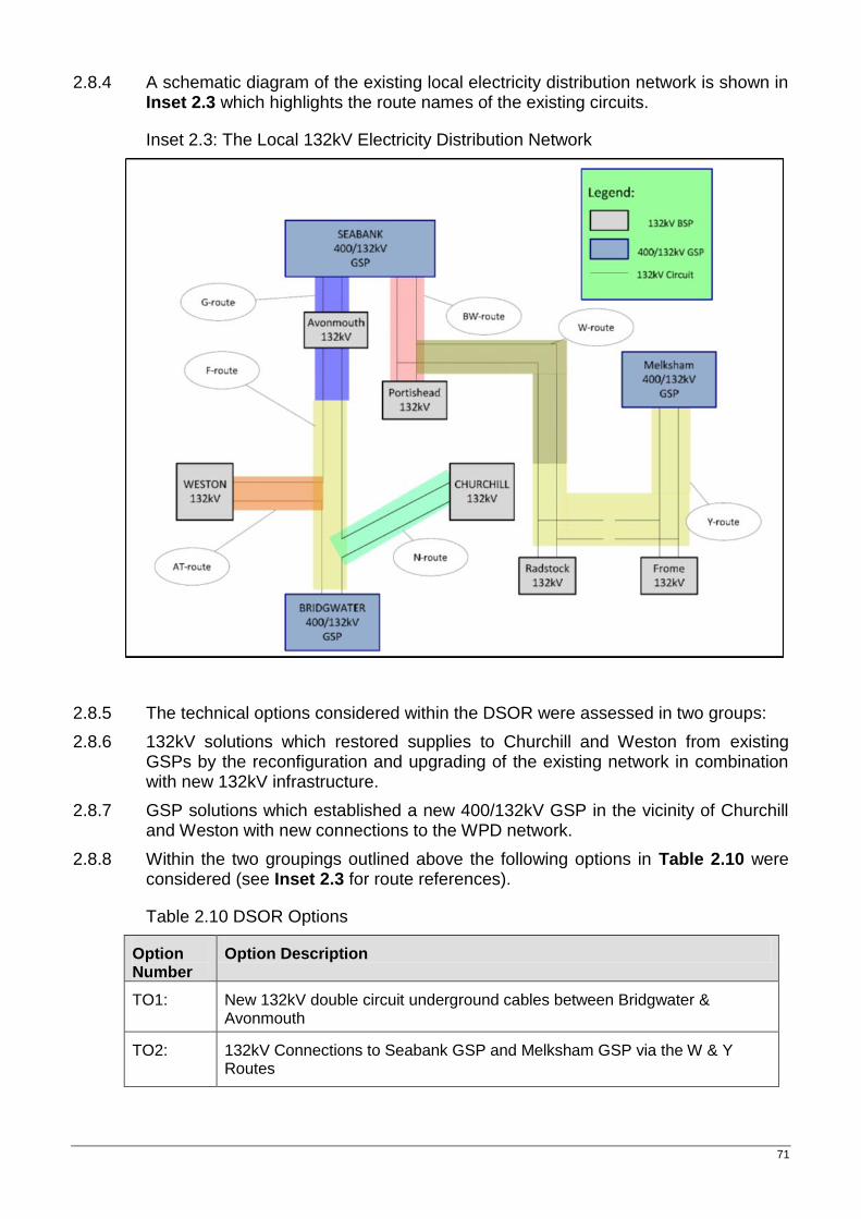
71
2.8.4 A schematic diagram of the existing local electricity distribution network is shown in Inset 2.3 which highlights the route names of the existing circuits.
Inset 2.3: The Local 132kV Electricity Distribution Network
2.8.5 The technical options considered within the DSOR were assessed in two groups:
2.8.6 132kV solutions which restored supplies to Churchill and Weston from existing GSPs by the reconfiguration and upgrading of the existing network in combination with new 132kV infrastructure.
2.8.7 GSP solutions which established a new 400/132kV GSP in the vicinity of Churchill and Weston with new connections to the WPD network.
2.8.8 Within the two groupings outlined above the following options in Table 2.10 were considered (see Inset 2.3 for route references).
Table 2.10 DSOR Options
Option Number
Option Description
TO1: New 132kV double circuit underground cables between Bridgwater & Avonmouth
TO2: 132kV Connections to Seabank GSP and Melksham GSP via the W & Y Routes
Hinkley Point C Connection Project – Volume 5.2.1
72
Option Number
Option Description
TO3: 132kV Connections to Seabank GSP & Bridgwater GSP via the W & a new F’ route
TO4: New 400/132kV GSP substation at Churchill and associated 400kV connections to the transmission system and 132kV connections to the distribution network.
TO5: New 400/132kV GSP substation in close proximity to the proposed 400kV transmission circuit and associated 132kV connections to the distribution network.
2.8.9 Three connection options: underground cables; overhead lines; and gas insulated lines were considered. Each technical option was assessed to determine which connection option would be most appropriate. Gas insulated lines were eliminated as options for the 132kV lines as they would provide no extra benefit at significant extra cost.
2.8.10 An options appraisal methodology based on multi-criteria analysis which considers relevant technical, environmental and socio-economic issues as well as the costs associated with each option was carried out.
Technical Appraisal
2.8.11 Each option was assessed to ensure its technical compliance with the standards set out in Engineering Recommendation P2/6 (ER P2/6) (Ref 2.2). This means that the implications of each option on technical compliance are fully assessed.
Economic Appraisal
2.8.12 Once the full scope of works associated with each option was identified an estimate of their capital cost is made. For the specific overhead line, underground AC cable and GIL components of each option operational lifetime costs were then estimated.
2.8.13 Capital cost is an estimate of the cost of equipment and installation costs. For the purposes of strategic optioneering, the cost estimates are based on generalised unit costs for the key elements of the option, reflecting recent contract values or manufacturers/consultant budget estimates. This is sufficient to allow a broad order of relative costs to be established for the options, as necessary at the strategic level, and is not intended to provide a detailed cost for each option which can only be obtained at the detailed design stage.
2.8.14 The lifetime cost is an estimate of the distribution, and transmission (where appropriate), losses and maintenance costs for the specific overhead line, underground AC cable (including shunt reactors) of the connection options over a 40 year lifetime.
Environmental Appraisal
2.8.15 The environmental appraisal for each of the options considered environmental constraints of international and national importance.
73
2.8.16 A high level planning policy analysis was undertaken to identify the main areas of economic importance in policy terms. The status of particular areas in employment terms is largely reflected in Development Plans and any supporting Economic Development Strategies, prepared by local authorities or regional bodies. Such documents were considered in the appraisal. The following planning policy areas relevant to socio-economic issues were considered where development implications might affect/be affected by technical options:
spatial settlement policies;
employment policies, including tourism;
recreation/leisure policies including green infrastructure;
areas of current/potential mineral workings;
other significant development proposals with impacts relevant to technical options; and
socio-economic effects were assessed to determine the extent to which they assisted in meeting policy objectives.
Appraisal Conclusions
2.8.17 The economic review showed that where new transmission or distribution connections are required AC overhead line technology would be the most economic of the options. AC underground cables and, in the case of 400kV, GIL are less economic.
2.8.18 An evaluation of socio-economic factors considered the potential impacts of each connection option on the main areas of economic importance in planning policy terms. It concluded that it was not possible to discriminate between options on the basis of the socio-economic evaluation.
2.8.19 The Bridgwater-Seabank (TO1) option had the least visual impact of all Technical Options as no overhead lines or substations were required. However, it would have been constrained by a number of national and international nature conservation and landscape designations including large areas of land (including ditches and rhynes) designated as SSSIs, settlements, Scheduled Monuments, Listed Buildings and woodlands. In addition, the significant cost of TO1 led to the conclusion that this option should only be pursued if there were no other acceptable options.
2.8.20 Both TO2 and TO3 had shorter connection lengths, lower capital and lifetime costs than TO1 and therefore would be preferred for further development.
2.8.21 TO2 would have had potential for effects over a wide area, including, the Cotswolds AONB, three SSSIs, two Registered Park and Gardens, Scheduled Monuments, Conservation Areas, Listed Buildings and woodland.
2.8.22 TO3 also had potential effects over a wide area, including, a number of national and international nature conservation and landscape designations, settlements, Scheduled Monuments, Listed Buildings and woodlands. The connection would need to cross the Huntspill River NNR and the Mendip Hills AONB (for approximately 6km) and would pass through the North Somerset and Mendip Bats SAC 5km consultation zone. A direct connection would also be constrained by settlements within the Somerset Levels and Moors and the Mendip Hills.
Hinkley Point C Connection Project – Volume 5.2.1
74
2.8.23 Further, although TO2 and TO3 were compliant with the minimum standards set out in ER P2/6 they reduce the flexibility, resilience and headroom for demand growth on the WPD network and as such do not provide a like for like replacement of the current network. This would disadvantage WPD and its customers in the Weston and Churchill areas and therefore neither TO2 nor TO3 were taken forward.
2.8.24 Both TO4 and TO5 provided sufficient resilience, flexibility and headroom for demand growth but required construction of a new GSP substation. Both TO4 and TO5 required new 132kV connections of similar lengths between the GSP and the AT Route which supplies Weston-Super-Mare. However, TO4 also required an additional 4.5km 400kV connection while TO5 did not. Differences in capital and lifetime costs show that option TO5 is therefore the most economic as it does not require a double circuit 400kV connection.
2.8.25 The DSOR concluded that Option TO5, which incorporated a new 400/132kV GSP substation in the Churchill/Sandford area, would best meet the range of technical, economic and environmental criteria and should be taken forward for further investigation.
2.8.26 The Report proposed that detailed studies should be undertaken to identify potential locations for the new GSP substation in the area between Sandford and Churchill, but focussed close to the corridor of the proposed 400kV connection to minimise the amount of additional infrastructure required.
Substation Siting Study
2.8.27 In response to the findings of the DSOR a Substation Siting Study (Volume 5.2.2.8, Appendix 2M) was produced to identify options for siting the GSP substation in the Churchill/Sandford area of North Somerset. The study described the high level planning and environmental constraints affecting the possible options and proposed a least environmentally constrained option.
2.8.28 Three areas, see Table 2.11, were identified as potentially suitable for the construction of a GSP substation (see Volume 5.2.3.3, Figure 2.8). The areas were large enough to accommodate either an air insulated substation or a gas insulated substation:
Table 2.11 Substation Areas of Search
Area Area Description
Area 1 Churchill Substation (a substation in the vicinity of the existing Churchill 132kV substation)
Area 2 West of Nye Road (a substation in the vicinity of the existing WPD 132kV F Route and N Route overhead lines including land to the rear of Thatcher’s Cider factory)
Area 3 East of Nye Road (a substation in the area beneath the WPD 132kV N Route overhead line, north of Sandford and west of Churchill Green)
75
Appraisal Criteria
2.8.29 Each of the search areas were assessed using National Grid’s internal guidance relevant to the siting of substations, referred to as the ‘Horlock Rules’, They were also assessed against the a range of environmental features that were present in the area between Churchill and Sandford and then compared to identify the area that would best avoid or minimise effects on the feature of interest (the ‘least environmentally constrained area’):
Appraisal Conclusions
2.8.30 A new GSP substation in Area of Search 2 (West of Nye Road) was identified as the least environmentally constrained option. This was the only option that required no new 400kV connections. Constructing the substation in this area would minimise the overall scale and extent of development within the open countryside and confine it to a more localised area adjacent to the corridor of the proposed 400kV Bridgwater to Seabank connection.
2.8.31 A site adjacent to Churchill substation in Area of Search 1 would be relatively unconstrained by planning and environmental factors, but required the replacement of the existing N Route 132kV overhead line with a new 400kV connection. The construction of a 400kV overhead line would increase the landscape and visual impact and the overall scale and extent of the development footprint in the open countryside. This was considered to outweigh the benefits of siting the substation close to the existing Churchill substation.
2.8.32 Potential sites west and east of Nye Road (Area of Searches 2 and 3 would require the construction of a new access road due to potential AIL access issues. Area of Search 3 (East of Nye Road) was considered more environmentally constrained than the other option due to the additional length of access road likely to be required (across the Strawberry Line and Nye Road), its location in ‘deeper’ open countryside in the sensitive Moors Landscape Character area (with little influence of existing electrical infrastructure), and the requirement for a 400kV connection of 1km in addition to a 132kV connection of 3km.
2.8.33 The study therefore concluded that a new GSP substation in an area of search to the West of Nye Road (Area 2) in the vicinity of Sandford represented the least environmentally constrained option.
2.8.34 A further appraisal (Volume 5.2.2.9, Appendix 2N) was undertaken to then identify the least environmentally constrained zone within Area 2 for a GSP substation.
2.8.35 Land adjacent to Nye Road in the north east of the Area 2 was identified as the least environmentally constrained zone for the substation (see Volume 5.2.3.3, Figure 2.8). It was noted that the substation should be sited to avoid the area identified as an extension of Flood Zone 3 on the NSC Level 1 SFRA mapping (climate change additional extents) in the least environmentally constrained zone.
2.8.36 A substation in this zone would maximise its distance from the AONB and residential settlement at Sandford, and minimise the number of properties in close proximity. Siting in the northern part of Area 2 would allow the substation to be constructed in a natural dip in landform which would reduce effects on landscape character, on surrounding views and could also assist in the attenuation of noise over distance compared with a substation on higher ground.
Hinkley Point C Connection Project – Volume 5.2.1
76
2.8.37 A substation design that would minimise the development footprint would be beneficial to avoid or minimise potential effects on landscape and views, ecology, water and buried archaeology. It was noted that a substation housed within a sensitively designed building to appear similar to other agricultural/industrial buildings in the area would minimise effects on landscape and views, and may provide opportunities for ecological mitigation within the design.
2.8.38 A substation in the north of the Area 2 would also minimise the length of new 132kV connection required to the AT Route (to Weston-super-Mare) as explained in 2.8.51.
Further Design Development
2.8.39 Following the decision to underground the 400kV connection through the Mendips Hills AONB it was decided to terminate the cable section at the new GSP substation. This would avoid the requirement for a cable sealing end compound in close proximity to the new substation and minimise effects on the Mendips AONB.
2.8.40 By terminating the underground cables at the new substation the proposed design of the substation had to be amended so as to accommodate the cable entries and further electrical compensation equipment required to offset the electrical effects of the long cable section.
2.8.41 This additional equipment increased the footprint requirements of the substation and also meant that the amount of equipment that would be housed externally had increased substantially.
2.8.42 National Grid assessed a range of substation technology options including indoor Gas Insulated Switchgear (GIS), outdoor Air Insulated Switchgear (AIS) and a Hybrid design (HIS).
2.8.43 An AIS substation would be completely outdoor, cover an area of 43,119m2 and cost in the region of £28.4m. A GIS substation would house some equipment in a building (approx 10% of overall footprint) but have an overall footprint of 22,147m2 and cost approximately £43.7m. A HIS substation would be completely outdoor, cover an area of 22,977m2 and cost approximately £34.5m.
2.8.44 It was concluded that a hybrid design of substation best met National Grid’s duties as it balanced the substation footprint and cost option. A GIS solution would have cost an additional £9.2m but provided little benefit in overall footprint size and the substation building would only have covered 10% of the overall footprint.
Representations Received
2.8.45 North Somerset Council advised that the proposed Area 2 West of Nye Road, Sandford1 was their preference and that any landscape and biodiversity impacts should be mitigated by designing the sub-station using Gas-Insulated Switchgear (GIS) with extensive landscaping and bat roosting features and swallow ledges.
77
2.8.46 The Mendips AONB Unit raised a number of concerns regarding the proposals and potential effects on the setting of and views from the AONB. They noted that the siting of the substation could not be considered in isolation from the other proposed infrastructure and therefore they would review their position when details of the overall scheme were available.
2.8.47 Representations from other stakeholders and the general public also supported the proposed substation location which was further away from the village of Sandford and located in a natural dip which would minimise potential noise effects.
2.8.48 In response to North Somerset Council further discussions were held to explain that following the proposal to underground the 400kV circuit through the Mendip Hills AONB there was a requirement to include extra equipment and modify the design of the Sandford Substation. The majority of equipment would now have to be sited outside.
2.8.49 As a result, relatively limited equipment would be included within a building and when considering the additional cost it was concluded that on balance gas insulated switchgear within a building is not worth pursuing.
2.8.50 On that basis a “hybrid” design of switchgear was proposed which although outdoor provides the footprint and height benefits of gas insulated switchgear and therefore limits the potential visual effects.
Route Corridor Study for AT Route Connection
2.8.51 The new GSP substation would also require a new 132kV connection to the existing 132kV overhead line route known as the AT Route that supplies Weston-Super-Mare. A Route Corridor Study was completed in May 20122 (Volume 5.2.2.9, Appendix 2O) that examined potential route corridor options for making this connection from the area to the west of Nye Road to the AT Route. The report also described high level planning and environmental constraints and identified the least environmentally constrained option.
2.8.52 The following corridors, see Table 2.12, were identified for consideration within the Route Corridor Study.
2 TEP: Western Power Distribution 132KV Route Corridor Study For Public Consultation (May 2012)
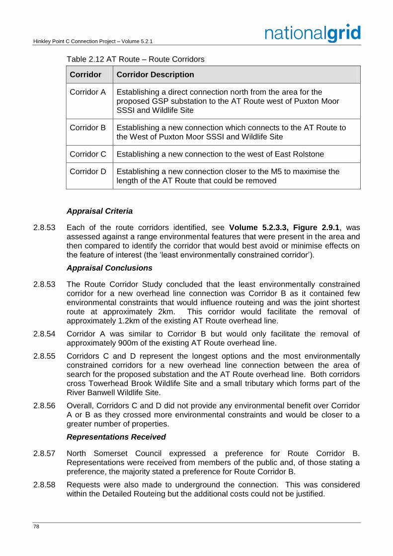
Hinkley Point C Connection Project – Volume 5.2.1
78
Table 2.12 AT Route – Route Corridors
Corridor Corridor Description
Corridor A Establishing a direct connection north from the area for the proposed GSP substation to the AT Route west of Puxton Moor SSSI and Wildlife Site
Corridor B Establishing a new connection which connects to the AT Route to the West of Puxton Moor SSSI and Wildlife Site
Corridor C Establishing a new connection to the west of East Rolstone
Corridor D Establishing a new connection closer to the M5 to maximise the length of the AT Route that could be removed
Appraisal Criteria
2.8.53 Each of the route corridors identified, see Volume 5.2.3.3, Figure 2.9.1, was assessed against a range environmental features that were present in the area and then compared to identify the corridor that would best avoid or minimise effects on the feature of interest (the ‘least environmentally constrained corridor’).
Appraisal Conclusions
2.8.53 The Route Corridor Study concluded that the least environmentally constrained corridor for a new overhead line connection was Corridor B as it contained few environmental constraints that would influence routeing and was the joint shortest route at approximately 2km. This corridor would facilitate the removal of approximately 1.2km of the existing AT Route overhead line.
2.8.54 Corridor A was similar to Corridor B but would only facilitate the removal of approximately 900m of the existing AT Route overhead line.
2.8.55 Corridors C and D represent the longest options and the most environmentally constrained corridors for a new overhead line connection between the area of search for the proposed substation and the AT Route overhead line. Both corridors cross Towerhead Brook Wildlife Site and a small tributary which forms part of the River Banwell Wildlife Site.
2.8.56 Overall, Corridors C and D did not provide any environmental benefit over Corridor A or B as they crossed more environmental constraints and would be closer to a greater number of properties.
Representations Received
2.8.57 North Somerset Council expressed a preference for Route Corridor B. Representations were received from members of the public and, of those stating a preference, the majority stated a preference for Route Corridor B.
2.8.58 Requests were also made to underground the connection. This was considered within the Detailed Routeing but the additional costs could not be justified.
79
2.8.59 Representations from this consultation, together with National Grid’s and WPD’s duties and guidance, planning, socio-economic, technical and cost considerations were used in reaching a decision on the preferred route corridor. The process leading to this decision is documented in the Local Electricity Network Preferred Options Report (Volume 5.2.2.9, Appendix 2P).
Further Detailed Design & Detailed Routeing
2.8.60 It was noted within the Route Corridor Study (Volume 5.2.2.9, Appendix 2O) that two single circuit wood pole lines were considered preferable to a double circuit steel lattice overhead line as the wood pole lines would be easier to assimilate into the landscape and would result in the least effect on views from residential properties.
2.8.61 However, in this area, due to a high risk of lightning strike and the consequential risk to electricity supplies in Weston-super-Mare, the overhead line must be shielded by an earth wire. An earth wire is present on the existing 132kV circuits in the area.
2.8.62 As well as carrying an earth wire, each individual wooden pole would have to be connected to earth via a copper earth tape.
2.8.63 There is no “off-the-shelf” design of wooden pole to meet these combined requirements and therefore any design would be bespoke to meet the need.
2.8.64 Further, the preferred route corridor travels through agricultural land and there would therefore be an on-going risk of damage to the earth tape from farm machinery. In addition there would be a risk of theft occurring as the copper earth tape would be accessible. Damage or theft of the earth tape could result in catastrophic damage to the wooden pole with a consequential effect on electricity supplies to Weston-super-Mare.
2.8.65 The risk of theft or damage would warrant an increase in inspection/testing and an increase in associated maintenance costs of the wooden poles.
2.8.66 Given the bespoke technical design requirements, the risks of damage and theft associated with the earth tape, and the consequential risk to electricity supplies in Weston-super-Mare, neither National Grid nor WPD considered a wooden pole design to be an option that should be pursued.
2.8.67 In light of the above, the following two overhead line technologies as well as underground cable were taken forward for detailed appraisal and alignment development (Volume 5.2.2.10, Appendix 2Q):
two steel “monopole” lines;
one line of “steel lattice” pylons, and
underground cables.
Appraisal Criteria
2.8.68 The following topics were addressed in the appraisal of the AT Route options:
Environment
landscape and visual amenity;
Hinkley Point C Connection Project – Volume 5.2.1
80
historic environment; and
ecology.
Socio-economic
local economic impact.
Cost
capital cost; and
lifetime cost.
Appraisal Conclusion
2.8.69 An underground cable was preferred from a landscape and views perspective compared to an overhead line connection. However, an overhead line option was preferred from an ecological and archaeological perspective as it avoids the negative effects of the larger construction swathe required for installing underground cables.
2.8.70 From a socio-economic perspective there were no marked differences that would favour one option in preference to the other.
2.8.71 In combination effects would not be a significant factor in determining which of the options should be taken forward for consultation.
2.8.72 The Capital Costs were estimated based on an engineering assessment of the route options and are given in Table 2.13.
Table 2.13 AT Route - Capital Cost Estimates
Option Capital Cost (£m)
Steel Lattice Pylons £1.54
Steel Monopoles £2.66
Underground Cables £3.00
2.8.73 On the basis of capital costs, the steel lattice pylon overhead line is the most economic. Underground cables are the least economic due to the significantly higher capital costs.
2.8.74 The proposed route, see Volume 5.2.3.3, Figure 2.9.2, does not lie in a particularly sensitive area (in terms of landscape designations) and it already contains overhead lines, which means they form part of the baseline conditions. When this is taken into account, alongside the significantly higher cost of putting the line underground, which would incur capital costs almost £1.5m higher than those of the steel lattice pylon and £0.5m higher than those of the steel monopole, National Grid
81
and WPD considered the benefits from using underground cables as an alternative to an overhead line in this location would not be outweighed by any extra economic, social and environmental benefits.
2.8.75 Having concluded that the use of underground cables was not justified in this area a comparison was made between the two overhead line options.
2.8.76 Whilst the steel monopoles are lower in height than the steel lattice pylons (approximately 22 metres compared to approximately 29 metres), there would be three times the amount of monopoles in the landscape compared to the steel lattice structures. The use of monopoles would also require two separate sets of overhead lines extending across the landscape in parallel approximately 25 metres apart, whereas a steel lattice pylon would only require one set of lines. The steel lattice structures also have greater permeability than the monopoles allowing views of background features to be seen through the pylons. Fundamentally, steel lattice pylons are already present in the landscape on the existing AT Route and F Route. As a result, the scale of change would be minimised by using steel lattice pylons compared to monopoles. Furthermore, a key factor in deciding which overhead line technology to take forward to consultation is that steel lattice pylons would cost approximately £1m less than steel monopoles.
2.8.77 On the basis of the above cost estimates and assessments, including the potential in combination effects of the proposed developments in the vicinity of the AT Route, National Grid and WPD considered that the steel lattice pylon design was preferred.
2.8.78 In addition, there was a requirement for a short section of undergrounding, approximately 600m, to connect the new AT Route to Sandford substation as the connection would have to be routed around the new substation and underneath the proposed 400kV overhead line.
Modification Works at Churchill Substation and Turn-in of Y and W Routes
2.8.79 In addition to the infrastructure changes to the local electricity network outlined previously modifications are also required in the area around Churchill Substation to maintain system security and network flexibility.
2.8.80 A study was undertaken (Volume 5.2.2.10, Appendix 2R) to consider the infrastructure modifications that were required in the vicinity of Churchill Substation to maintain the local distribution system’s security of supply for customers at existing levels.
2.8.81 An additional WPD 132kV double circuit overhead line, the W and Y Routes runs from Portishead Substation to Radstock Substation, and it is proposed to ‘turn-in’ one of the circuits from each of the W and Y Routes to provide a connection to Churchill Substation.
2.8.82 This would mean that the W Route would connect Churchill Substation to Portishead Substation and the Y Route would connect Churchill Substation to Radstock Substation.
2.8.83 To connect these additional circuits to Churchill Substation the existing substation will need to be extended and additional equipment installed.
2.8.84 The footprint of the existing Churchill Substation is approximately 70m x 120m. At their closest points, the existing W and Y Routes are approximately 250m from the substation.
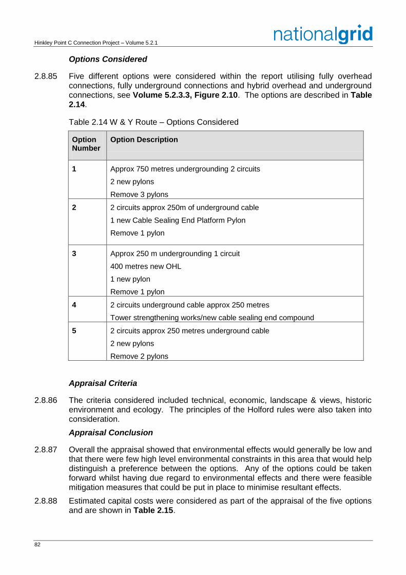
Hinkley Point C Connection Project – Volume 5.2.1
82
Options Considered
2.8.85 Five different options were considered within the report utilising fully overhead connections, fully underground connections and hybrid overhead and underground connections, see Volume 5.2.3.3, Figure 2.10. The options are described in Table 2.14.
Table 2.14 W & Y Route – Options Considered
Option Number
Option Description
1 Approx 750 metres undergrounding 2 circuits
2 new pylons
Remove 3 pylons
2 2 circuits approx 250m of underground cable
1 new Cable Sealing End Platform Pylon
Remove 1 pylon
3 Approx 250 m undergrounding 1 circuit
400 metres new OHL
1 new pylon
Remove 1 pylon
4 2 circuits underground cable approx 250 metres
Tower strengthening works/new cable sealing end compound
5 2 circuits approx 250 metres underground cable
2 new pylons
Remove 2 pylons
Appraisal Criteria
2.8.86 The criteria considered included technical, economic, landscape & views, historic environment and ecology. The principles of the Holford rules were also taken into consideration.
Appraisal Conclusion
2.8.87 Overall the appraisal showed that environmental effects would generally be low and that there were few high level environmental constraints in this area that would help distinguish a preference between the options. Any of the options could be taken forward whilst having due regard to environmental effects and there were feasible mitigation measures that could be put in place to minimise resultant effects.
2.8.88 Estimated capital costs were considered as part of the appraisal of the five options and are shown in Table 2.15.
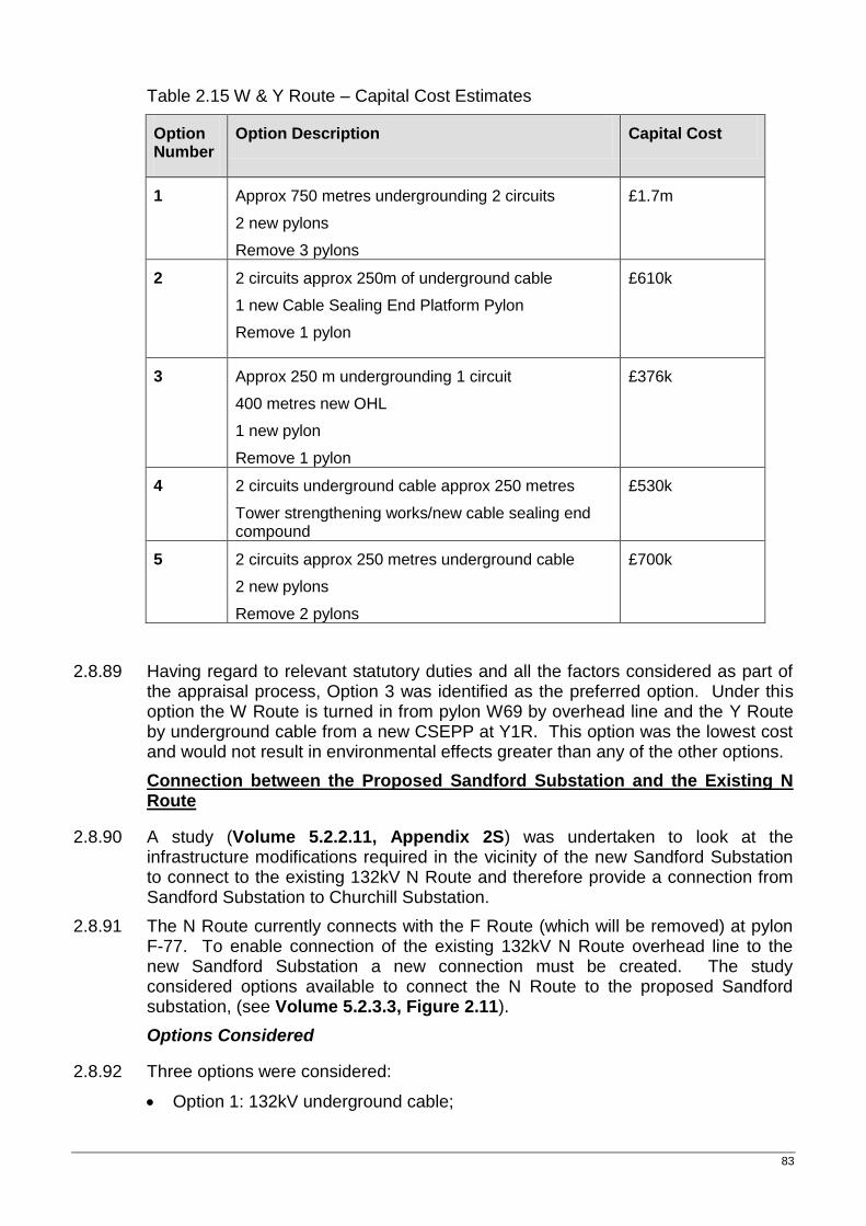
83
Table 2.15 W & Y Route – Capital Cost Estimates
Option Number
Option Description Capital Cost
1 Approx 750 metres undergrounding 2 circuits
2 new pylons
Remove 3 pylons
£1.7m
2 2 circuits approx 250m of underground cable
1 new Cable Sealing End Platform Pylon
Remove 1 pylon
£610k
3 Approx 250 m undergrounding 1 circuit
400 metres new OHL
1 new pylon
Remove 1 pylon
£376k
4 2 circuits underground cable approx 250 metres
Tower strengthening works/new cable sealing end compound
£530k
5 2 circuits approx 250 metres underground cable
2 new pylons
Remove 2 pylons
£700k
2.8.89 Having regard to relevant statutory duties and all the factors considered as part of the appraisal process, Option 3 was identified as the preferred option. Under this option the W Route is turned in from pylon W69 by overhead line and the Y Route by underground cable from a new CSEPP at Y1R. This option was the lowest cost and would not result in environmental effects greater than any of the other options.
Connection between the Proposed Sandford Substation and the Existing N Route
2.8.90 A study (Volume 5.2.2.11, Appendix 2S) was undertaken to look at the infrastructure modifications required in the vicinity of the new Sandford Substation to connect to the existing 132kV N Route and therefore provide a connection from Sandford Substation to Churchill Substation.
2.8.91 The N Route currently connects with the F Route (which will be removed) at pylon F-77. To enable connection of the existing 132kV N Route overhead line to the new Sandford Substation a new connection must be created. The study considered options available to connect the N Route to the proposed Sandford substation, (see Volume 5.2.3.3, Figure 2.11).
Options Considered
2.8.92 Three options were considered:
Option 1: 132kV underground cable;
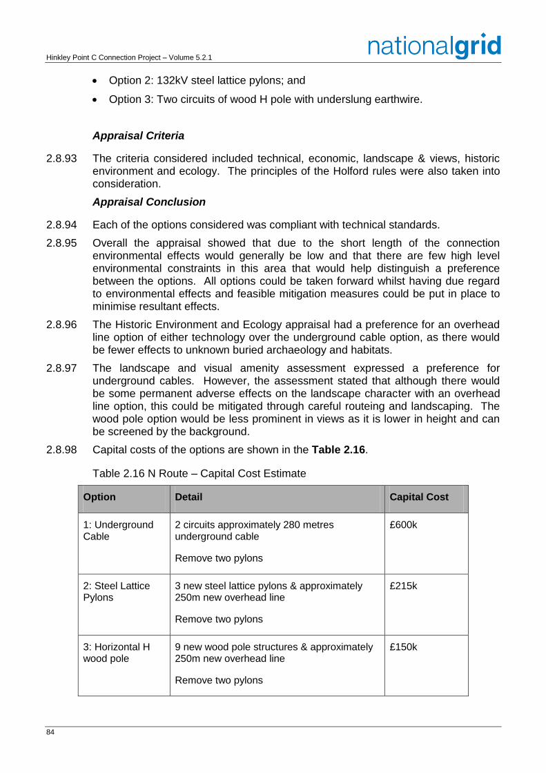
Hinkley Point C Connection Project – Volume 5.2.1
84
Option 2: 132kV steel lattice pylons; and
Option 3: Two circuits of wood H pole with underslung earthwire.
Appraisal Criteria
2.8.93 The criteria considered included technical, economic, landscape & views, historic environment and ecology. The principles of the Holford rules were also taken into consideration.
Appraisal Conclusion
2.8.94 Each of the options considered was compliant with technical standards.
2.8.95 Overall the appraisal showed that due to the short length of the connection environmental effects would generally be low and that there are few high level environmental constraints in this area that would help distinguish a preference between the options. All options could be taken forward whilst having due regard to environmental effects and feasible mitigation measures could be put in place to minimise resultant effects.
2.8.96 The Historic Environment and Ecology appraisal had a preference for an overhead line option of either technology over the underground cable option, as there would be fewer effects to unknown buried archaeology and habitats.
2.8.97 The landscape and visual amenity assessment expressed a preference for underground cables. However, the assessment stated that although there would be some permanent adverse effects on the landscape character with an overhead line option, this could be mitigated through careful routeing and landscaping. The wood pole option would be less prominent in views as it is lower in height and can be screened by the background.
2.8.98 Capital costs of the options are shown in the Table 2.16.
Table 2.16 N Route – Capital Cost Estimate
Option Detail Capital Cost
1: Underground Cable
2 circuits approximately 280 metres underground cable
Remove two pylons
£600k
2: Steel Lattice Pylons
3 new steel lattice pylons & approximately 250m new overhead line
Remove two pylons
£215k
3: Horizontal H wood pole
9 new wood pole structures & approximately 250m new overhead line
Remove two pylons
£150k
85
2.8.99 Having regard to statutory duties and all the factors considered as part of the appraisal process, WPD and National Grid considered that Option 3 was the preferred technical and environmental option. Under this option the existing N Route will be connected to the proposed Sandford GSP by two circuits of 132kV horizontal H wood pole structures.
2.8.100 Option 3 was the lowest capital cost option. It was almost £500k cheaper than the cost to underground this section. Whilst this option will introduce more structures to the landscape, the landscape and visual assessment stated that as they are lower in height they are easier to screen/background.
Other Infrastructure Changes Required to the Local Electricity (Distribution) Network
Western Power Distribution 132kV W Route Undergrounding
2.8.101 In November 2012, National Grid announced its draft route for the 400kV transmission connection. Due to development at Stone-edge Batch and Tickenham, and blocks of ancient woodland on Tickenham Ridge, National Grid identified that sections of the existing WPD 132kV W Route overhead line would need to be undergrounded to facilitate the construction of the 400kV overhead line in the same area. To further minimise the effects of the proposed connection in this area it was concluded that the W Route should be undergrounded from a point south west of Nailsea to Portishead substation (a distance of approximately 8.7km).
Options Considered
2.8.102 A study (Volume 5.2.2.11, Appendix 20) was undertaken which identified two technically feasible underground cable routes, (see Volume 5.2.3.4, Figure 2.12.1 – 2.12.2):
Green Route: Shortest possible route. 10km, to the north west of Nailsea, using highways and rural areas; and
Blue Route: Use existing highways to install two single circuits: Route A - 14.7km and Route B – 12.9km.
Appraisal Criteria
2.8.103 The criteria considered included technical, economic, landscape and views, historic environment and ecology. Local economic impact was also considered.
Appraisal Conclusion
2.8.104 Each of the options considered was compliant with technical standards.
2.8.105 The Historic Environment and Ecology appraisal had a preference for the blue route, as there would be fewer effects to unknown buried archaeology and habitats associated with a route along highways.
2.8.106 The landscape and visual amenity assessment did not express a preference for either route.
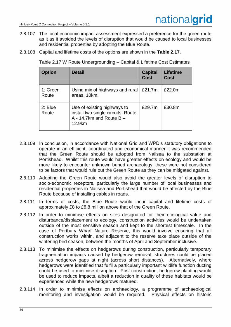
Hinkley Point C Connection Project – Volume 5.2.1
86
2.8.107 The local economic impact assessment expressed a preference for the green route as it as it avoided the levels of disruption that would be caused to local businesses and residential properties by adopting the Blue Route.
2.8.108 Capital and lifetime costs of the options are shown in the Table 2.17.
Table 2.17 W Route Undergrounding – Capital & Lifetime Cost Estimates
Option Detail Capital Cost
Lifetime Cost
1: Green Route
Using mix of highways and rural areas, 10km.
£21.7m £22.0m
2: Blue Route
Use of existing highways to install two single circuits: Route A - 14.7km and Route B – 12.9km
£29.7m £30.8m
2.8.109 In conclusion, in accordance with National Grid and WPD’s statutory obligations to operate in an efficient, coordinated and economical manner it was recommended that the Green Route should be adopted from Nailsea to the substation at Portishead. Whilst this route would have greater effects on ecology and would be more likely to encounter unknown buried archaeology, these were not considered to be factors that would rule out the Green Route as they can be mitigated against.
2.8.110 Adopting the Green Route would also avoid the greater levels of disruption to socio-economic receptors, particularly the large number of local businesses and residential properties in Nailsea and Portishead that would be affected by the Blue Route because of installing cables in roads.
2.8.111 In terms of costs, the Blue Route would incur capital and lifetime costs of approximately £8 to £8.8 million above that of the Green Route.
2.8.112 In order to minimise effects on sites designated for their ecological value and disturbance/displacement to ecology, construction activities would be undertaken outside of the most sensitive season and kept to the shortest timescale. In the case of Portbury Wharf Nature Reserve, this would involve ensuring that all construction works within, and adjacent to the reserve take place outside of the wintering bird season, between the months of April and September inclusive.
2.8.113 To minimise the effects on hedgerows during construction, particularly temporary fragmentation impacts caused by hedgerow removal, structures could be placed across hedgerow gaps at night (across short distances). Alternatively, where hedgerows were identified that fulfil a particularly important wildlife function ducting could be used to minimise disruption. Post construction, hedgerow planting would be used to reduce impacts, albeit a reduction in quality of these habitats would be experienced while the new hedgerows matured.
2.8.114 In order to minimise effects on archaeology, a programme of archaeological monitoring and investigation would be required. Physical effects on historic
87
landscape elements (i.e. physical features) could be avoided, or mitigated through archaeological recording, careful reinstatement and, in the case of some hedgerow loss, translocation or appropriate replanting could be used.
2.8.115 In light of the above, National Grid and WPD considered that the Green Route was the preferred option, see Volume 5.2.3.4, Figure 2.13.
Western Power Distribution – Undergrounding Cable Sealing End Platform Pylon Location Technical and Environmental Appraisal
2.8.116 For the undergrounding of the W Route, as described above, a transition from overhead line to underground cables would be achieved via a cable sealing end platform pylon (CSEPP). A study (Volume 5.2.2.11, Appendix 2U) was undertaken to appraise options against technical, environmental and socio-economic factors and make a recommendation on which location should be taken forward as the preferred location for a CSEPP.
Options Considered
2.8.117 The section of the existing overhead line between the Bristol to Weston-super-Mare railway line and West End Lane on the outskirts of Nailsea was identified as a potentially suitable area to assess where to construct a CSEPP. This was separated into southern, central and northern sections for the assessments. Within each section, a number of existing pylons were identified as being potential locations for the CSEPP. These were numbered W34 to W42.
Appraisal Criteria
2.8.118 The criteria considered included technical, economic, landscape & views, historic environment and ecology. Socio-economic impact was also considered.
Appraisal Conclusion
2.8.119 From a landscape and visual amenity perspective and a historic environment perspective, a CSEPP in the southern section at pylon W42 to the north of River Kenn was considered to be the least environmentally constrained site as it minimised effects on landscape character and visual amenity and above ground historic environment features compared to the other pylon locations.
2.8.120 From an ecological perspective, a CSEPP in the northern section at W34 was preferred as it would have fewer ecological effects than the other pylons.
2.8.121 Socio economic considerations did not provide a differentiating factor between the proposed CSEPP locations, although a CSEPP at the Nailsea Rugby Ground in the northern section was likely to cause temporary negative impacts during construction and on-going impacts through reduced parking provision.
2.8.122 The most economical option was to site the CSEPP in the northern section of the Study Area as this minimised the length and therefore the cost of 132kV underground cable. However, this would result in a CSEPP being visible from the large number of receptors along the western edge of Nailsea. Siting a CSEPP in the southern section would have beneficial effects on landscape character and visual amenity as it could be sited on lower ground of the River Kenn valley closest to the railway and would extend the length of undergrounding improving views from receptors in Nailsea. This would however incur additional costs of between £2.5 million and £3.5 million as a result of the greater amount of undergrounding required compared to a CSEPP in the northern section.
Hinkley Point C Connection Project – Volume 5.2.1
88
2.8.123 Following technical, environmental and economic assessments, it was concluded that a CSEPP in the northern section at pylon W36 would minimise the costs of the proposed development whilst seeking to minimise environmental effects as far as practicable.
Western Power Distribution 132kV G Route Undergrounding
2.8.124 In November 2012, National Grid published its draft route for the 400kV transmission connection. Following discussion with affected businesses it was noted that the draft route in Avonmouth Docks passed close to a site that recycles metal and requires 24 hour access for the fire service due to the nature of their operations and the potential for fires and explosions. Routeing an overhead line over this site had the potential to have serious safety issues which may affect the operation of a transmission circuit.
2.8.125 Alternative route options in the vicinity of this business were considered but were not feasible due to the adjacent railway line, buildings and coal conveyor and operational restrictions associated with the Port’s activities. As a result an alternative overhead line route that avoided the site by exiting the Port to the south of King Road Avenue was been developed.
2.8.126 The proposed overhead line route uses the corridor of WPD’s existing 132kV overhead line, known as the G Route, for approximately 2km. As a result it is proposed to underground this 2km section of the G Route.
Options Considered
2.8.127 A study (Volume 5.2.2.11, Appendix 2V) was undertaken which identified two technically feasible underground cable routes. Both options start at Avonmouth substation and travel along Avonmouth Way road, pass through Kings Weston Lane and continue in a north easterly direction. The routes pass next to Merebank Rhine.
2.8.128 The routes then pass underneath the M49. Crossing the motorway poses a technical constraint to routeing and will be done either by using the existing infrastructure such as an existing culvert or by HDD. This will be determined through further technical assessment. The route continues north through agricultural fields parallel to the M49.
2.8.129 The end points of the cable routes are different and described below:
Option 1: 2.1km. The undergrounding ends at a CSEPP just south of a clump of ash trees by the railway line.; and
Option 2: 1.95km. The ends at a CSEPP just north of the unconnected M49 flyover, just north of pylon BW13.
Appraisal Criteria
2.8.130 The criteria considered included technical, economic, landscape and views, historic environment and ecology.
89
Appraisal Conclusion
2.8.131 The environmental appraisal concluded that there was little to differentiate between the two options based on ecology and historic environment. However, from a landscape and views perspective Option 2 was considered to be the least constrained as the CSEPP required would be smaller and sited distant from existing pylon G32.
2.8.132 Estimated capital and lifetime costs did not differentiate between the options.
2.8.133 Having regard to their statutory duties and all the factors considered, National Grid and WPD concluded that Option 2 was the preferred option.
Undergrounding of Sections of 132kV Overhead Line: BW Route and Seabank Line Entries
2.8.134 In a few instances, the proposed routeing of the 400kV overhead line encroaches on the safety clearances required from a number of 132kV overhead lines owned and operated by WPD. In these limited areas it is proposed to underground the affected 132kV circuits. A study (Volume 5.2.2.11, Appendix 2V) was undertaken which explained the detailed interaction between the 400kV and 132kV overhead lines, and the details of the proposed underground sections which are summarised below.
2.8.135 The following 132kV overhead lines are proposed to be undergrounded:
BW Route;
G Route, and the
DA Route.
2.9 Section 42, 47 and 48 Consultation
2.9.1 Consultation (Section 42, 47 and 48) on the Proposed Development, see Volume 5.2.3.4, Figure 2.14, took place over an eight week period between 3 September and 29 October, 2013. Statutory and non-statutory consultees and members of the public were included within the consultation.
2.9.2 1,635 representations were received during the consultation many of which included requests to consider alternatives to the Proposed Development. These included requests to consider alternate strategic options and alternate route corridors options which have been described in the relevant section above.
2.9.3 The remaining representations which requested a change to the design of the Proposed Development were considered using a Change Control Process which is summarised below.
2.9.4 The majority of the change requests related to common sections of the Proposed Development and therefore, although documented individually, were considered as part of a group. As such they are described below in clusters.
Change Control Process
2.9.5 A structured change request process was implemented to address all requests for changes to the Proposed Development following consultation. The process was developed to ensure that each change request was effectively assessed by a
Hinkley Point C Connection Project – Volume 5.2.1
90
number of specialist areas covering, planning, environment, design & construction and land rights.
2.9.6 The change requests and supporting documentation were managed using change control software to ensure all decisions were recorded and an audit trail of the reasons for changes being made or rejected was recorded.
2.9.7 The procedure was applied to all requests for changes to the location and/or design of proposed infrastructure or access works associated with the Proposed Development. This included any associated works on the WPD network. Change requests were raised in relation to the overhead line and cable alignments, individual pylon locations, substations, sealing end compounds and access routes.
2.9.8 A number of stages were included in the process, see the flow chart show in Inset 2.4.
Initiating Requests
2.9.9 Any change to change the Proposed Development required a Change Request Form (CR) to be raised. The CR clearly stated the reason for the request, including sketches/photographs where available. A change request number was allocated and the CR was forwarded for a preliminary impact assessment.
Preliminary Impact Assessment
2.9.10 During preliminary impact assessment (PIA) heads of department in planning, design, construction, land rights and environment were required to make an initial assessment as to whether there were valid reasons to consider the request. Some CR’s were rejected at this stage if for example they were a duplication of another request already in the system.
2.9.11 If all parties agreed that the request was valid and should be evaluated further then the CR progressed for an engineering study to be completed.
2.9.12 If there was a split decision in PIA on whether the CR should be progressed then it was referred to a review meeting where the CR was discussed and a decision made on whether it should be progressed to engineering study.
Engineering Study
2.9.13 A feasibility study was completed to assess the engineering options and implications of the CR. The engineering study was verified and passed to the Design Manager for review before circulating to other departments for their full impact assessment.
Full Impact Assessment
2.9.14 Heads of department in planning, construction, land rights and environment reviewed all relevant information on the CR including the output from the engineering study so that a decision on whether to include the change in the final design could be made. Where required more detailed assessments were carried out by the relevant specialists on the implications of the CR for example a number of environmental specialists may have been asked to consider the implications of a particular change.
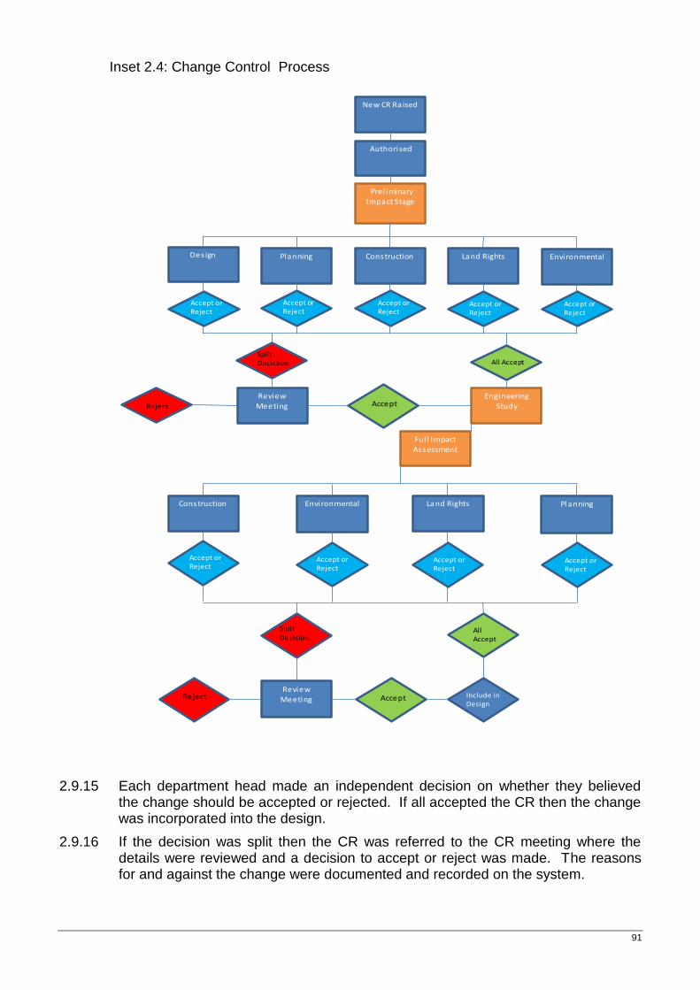
91
Inset 2.4: Change Control Process
New CR Raised
Authorised
Prel iminary Impact Stage
EnvironmentalDes ign Planning Construction Land Rights
Engineering
StudyReview
Meeting
Ful l Impact Assessment
Accept or Reject
Accept or Reject
Accept or Reject
Accept or Reject
Accept or Reject
SplitDecisiion All Accept
Reject
Construction Environmental Land Rights Planning
Accept or Reject
Accept or Reject
Accept or Reject
Accept or Reject
Review Meeting
SplitDecision
All Accept
Accept Include in Design
Reject
Accept
2.9.15 Each department head made an independent decision on whether they believed the change should be accepted or rejected. If all accepted the CR then the change was incorporated into the design.
2.9.16 If the decision was split then the CR was referred to the CR meeting where the details were reviewed and a decision to accept or reject was made. The reasons for and against the change were documented and recorded on the system.
Hinkley Point C Connection Project – Volume 5.2.1
92
Assessment of Change Requests
2.9.17 The majority of change requests related to common areas of the route and although often similar, on occasion, were in conflict with each other.
2.9.18 The change requests were therefore grouped so that they could be holistically addressed in location based clusters. The clusters considered were as follows:
Cluster A: Horsey Level to Woolavington Level.
Cluster B: Southwick/Mark.
Cluster C: Tarnock.
Cluster D: Sandford to Puxton.
Cluster E: Nailsea.
Cluster F: Tickenham.
Cluster G: Portishead.
Cluster H: Portishead Substation.
Cluster I: Avonmouth South.
Cluster J: Avonmouth North.
Cluster K: Severnside.
Cluster L: Seabank Substation.
2.9.19 The cluster assessments are summarised below.
Cluster A: Horsey Level to Woolavington Level
2.9.20 During the statutory Stage 4 consultation, a number of suggestions were received from prescribed consultees and members of the community regarding both the design of the proposed pylons and the route of the overhead line in Section A (Puriton Ridge). These representations included suggestions that the T-pylon would offer advantages over the traditional steel lattice pylons and therefore should be adopted in this area and suggestions on alternative routes that should be considered including a route to the east of Chisland Covert and a route to the west of East Farm and Hillside Farm, see Volume 5.2.3.5, Figure 2.15 – 2.16.
2.9.21 These requests for changes were considered and appraised by National Grid through the change control process.
Pylon Design
2.9.22 A number of prescribed consultees including the Joint Councils and Woolavington Parish Council requested that National Grid consider whether the T-pylon could replace lattice pylons on Puriton Ridge. Comments were also received from Natural England and the RSPB which suggested that the lower height and vertically compressed conductor arrangement of the T-pylon would be preferential when considering the potential for collision risk for SPA bird species flying between the Severn Estuary and Somerset Levels & Moors SPA sites.
93
2.9.23 The original assessments undertaken as part of the Pylon Design Options Report indicated a marginal preference for the use of steel lattice pylons with low height steel lattice pylons on the top of the ridge. Further detailed assessment of the effects of steel lattice pylons and T-pylons on landscape and views in Section A was undertaken as part of the PEIR. This assessment concluded that the steel lattice pylon would give rise to lower levels of effect where the existing overhead lines on steel lattice pylons would be visible (275kV VQ Route in Section A and the 400kV ZG Route in Section B) and in near distance views where the T-pylon would be more prominent. However, the T-pylon would have less adverse effects on receptors in middle distance and distant views due to the reduced height of pylons and the greater effectiveness of filtering and screening. Overall, whilst there would be slight differences in the effects between the different pylon designs with respect to landscape and views these would be within the same level of significance and would therefore not be a material differentiator between the choice of pylon designs.
2.9.24 Further detailed assessment of the effects of steel lattice pylon and T-pylons on the historic environment in Section A was also undertaken as part of the PEIR. This assessment concluded that due to the removal of the existing 132kV F Route overhead line and the lower height of the T-pylons, the T-pylon would be preferable to steel lattice pylons in Section A as they would result in a beneficial effect on the setting of the Grade II listed Bradney House and a lower magnitude of effect on the Grade II listed Horsey Manor Farm.
2.9.25 From an ecological perspective it was considered that the reduced height of the T-pylons and the configuration of the conductors would reduce the risk of collision for birds. It is anticipated that this would result in a slight reduction in collision risk but within the same level of significance. With this in mind, Natural England requested that National Grid use this design to minimise potential adverse effects.
2.9.26 The use of T-pylons in this area would result in reduced effects on two Grade II listed buildings and would reduce the risk of collision for birds. This pylon design would also not result in an increase in landscape and visual effects or technical and engineering difficulties greater than the alternative option and as a result National Grid has included the suggested change within its DCO application.
Detailed Routeing
2.9.27 In accordance with Holford Rule 4, the proposed route across Puriton Ridge was selected to cross the ridge obliquely and maximise the potential for backgrounding of the overhead line by utilising gently sloping ground and passing between blocks of woodland. A route to the east of Chisland Covert, see Volume 5.2.3.5, Figure 2.15, would utilise a slightly steeper gradient making it more visible in the local landscape and would bring the route very close to Knowle Hall, its associated historic landscape and other residential properties in the vicinity of the Hall. As a result this option would be less compliant than the proposed route with respect to Holford Rule 2. Whilst a route to the east of Chisland Covert would be slightly further away from the edge of Puriton and footpaths on Puriton Ridge, this would not offset the increase in adverse effects on the historic setting and residents of Knowle Hall and other residential receptors in the vicinity of the Hall and as a result this change was not included within National Grid’s DCO application.
2.9.28 The route in Section A forms a link between the existing 275kV overhead line (proposed to be uprated to 400kV operation) on Horsey Level and the existing 400kV overhead line that runs north of Woolavington to Melksham. The route
Hinkley Point C Connection Project – Volume 5.2.1
94
proposed as part of the statutory Stage 4 consultation was the most direct and affords the greatest benefits by allowing the removal of a short section of the existing Hinkley to Melksham 400kV overhead line. This route also maintained separation from the settlements of Woolavington and Puriton in an attempt to minimise effects on visual amenity. A route to the west of Hillside Farm would increase the length of the route and would require additional pylons. This route would also bring the overhead line closer to the settlement of Puriton and would affect the future development of the Puriton Energy Park, see Volume 5.2.3.5, Figure 2.16. As a route to the West of Hillside Farm was longer and therefore less compliant with the Holford Rules than the route put forward during the statutory Stage 4 consultation the suggested changes were not included within the DCO application.
Cluster B: Mark and Southwick
2.9.29 During the statutory Stage 4 consultation and the subsequent localised consultation, a number of suggestions were received from prescribed consultees and members of the community regarding the route of the 400kV overhead line and the position of the pylons in the areas of Southwick and Mark Causeway, see Volume 5.2.3.5, Figure 2.17. These representations included suggestions that the route of the overhead line should be routed to the east of Southwick; that a more central alignment should be adopted between Court Farm and Wainbridge Farm; that the route should be significantly rerouted to pass to the east of the settlement of Mark, between Mark and Blackford; that the route should travel east of and parallel to Butt Lake and Tile House Roads for as far as possible; that the route should follow the existing WPD 132kV overhead line to cross Mark Causeway; and that the route of the overhead line should be moved closer to Court Farm to minimise effects on Wainbridge Farm and avoid a single mature tree present within the hedgerow.
2.9.30 These requests for changes to the route of the overhead line and positioning of the pylons were considered and appraised by National Grid through the change control process.
Route to the East of Southwick
2.9.31 In accordance with the Holford Rules, the route proposed during the statutory Stage 4 consultation was routed to be as straight and direct as possible to minimise the length of overhead line, the number of changes in direction and minimise the scale of change in the landscape.
2.9.32 A route to the east of Southwick would be slightly longer and therefore less direct than the route illustrated during the statutory Stage 4 consultation, however it would require the same number of pylons and changes in direction and therefore the difference in length would not be a material differentiator between the options. A route to the east of Southwick would also be further away from the existing 132kV overhead line which would result in a greater scale of change and effect on the landscape than the statutory Stage 4 alignment. However this increase in effect would be within the same category of significance (moderate adverse).
2.9.33 A route to the east of Southwick would take the overhead line away from farms and residential properties in proximity to the route in Southwick resulting in less effect on sensitive visual receptors (a PRoW and houses) because it would be more
95
distant from them. On the statutory Stage 4 consultation alignment a major adverse effect was anticipated on the southern section of PRoW AX23/3. As a result of routeing to the east of Southwick this effect would reduce to moderate adverse as the route is further away and no longer passes over the PRoW. This route would also introduce a new 400kV overhead line further away in oblique views from Chestnut Farm, reducing the significance of visual effects from moderate to minor adverse. The proposed re-alignment would also be south of Knowle View Farm and heavily filtered and screened by trees, resulting in no greater than a minor adverse significance of effect compared to the moderate adverse effect assessed in relation to the statutory Stage 4 consultation alignment (which would be north of the dwelling in open views).
2.9.34 Overall, whilst a route to the east of Southwick would have a slightly greater scale of change in the landscape it would result in a reduction in the effects on views from a number of receptors including PRoW AX23/3, Chesnut Farm and Knoll View Farm. As a result, National Grid considered that there would be benefits in adopting this route and held a localised public consultation on its revised proposals in this area between 10 February and 10 March, 2014. Following this consultation and an analysis of the feedback received, National Grid concluded that the revised route was preferred and therefore included this change within its DCO application.
Central Alignment between Court Farm and Wainbridge Farm
2.9.35 The route proposed during the statutory Stage 4 consultation across Mark Causeway utilised a gap between residential properties to the north and south of the Causeway. The purchase of a residential property to the south of the Causeway by National Grid and the proposal to demolish this property resulted in a larger gap through which to route the overhead line.
2.9.36 In accordance with the supplementary note to the Holford Rules on routeing close to residential areas and National Grid’s approach to the design and routeing of new transmission lines a more central alignment which sought to maximise distance to both properties as far as possible was considered preferable. Although this change in route would move the route slightly closer to Wainbridge Farm the scale of effect on this property would not differ as a result of the change. As a result this change was included within National Grid’s DCO application as part of a larger change to the route to the north and south of Mark Causeway.
Route to the East of Mark
2.9.37 A route to the east of Mark, between the settlements of Mark and Blackford is not dissimilar to Route Corridor 2 which was identified, assessed and discounted as part of outline routeing studies. In response to feedback received during the statutory Stage 4 consultation, National Grid reviewed its previous decisions but concluded that the reasons for discounting this route, namely that it would be longer, less direct and would result in greater effects on landscape, views and ecology than National Grid’s proposed route remained valid. As a result this change was not included within National Grid’s DCO application.
Route Parallel to Butt Lake and Tile House Roads
2.9.38 Butt Lake Road and Tile House Road travel in a south easterly direction away from Mark Causeway. To achieve a route east of and parallel to these roads a large diversion of the overhead line would be required. This would either start to the south of Cripps Farm and travel in a north easterly direction, before changing
Hinkley Point C Connection Project – Volume 5.2.1
96
direction on Mark Moor and travelling towards the gap between Wainbridge Farm, and Court Farm on Mark Causeway or would involve a sharp change in direction to the north of Cripps Farm before travelling north east, changing direction on Mark Moor and adopting a route similar to that described above.
2.9.39 Both of these route options would be longer, less direct and would involve a number of sharp changes in direction. As a result the routes would be less compliant with Holford Rule 3 than the route included within the statutory Stage 4 consultation. Due to their divergence away from the route of the existing 132kV overhead line and the large changes in direction required both routes would also result in a greater scale of change in the landscape and greater effects on landscape and views.
2.9.40 As a route east and parallel to Butt Lake Road and Tile House Road would be longer, less direct, would involve a number of sharp changes in direction and would result in increased landscape effects compared to National Grid’s proposed route National Grid has not included this change within its DCO application.
Route along the Existing WPD 132kV Overhead Line
2.9.41 As part of the identification of the draft route in 2012, National Grid considered a potential route alignment that crossed Mark Causeway along the route of the existing 132kV overhead line. Adopting this route would involve oversailing a caravan park and passing in close proximity to a number of residential properties and a school. Routeing within a slightly larger gap in built form to the east of Harp Road would maximise the distance of the overhead line to residential properties as far as possible whilst also avoiding oversail of the caravan park and maximising distance to the school. In response to the representations received, National Grid back-checked and reviewed its previous decisions about diverting away from the route of the 132kV overhead line but considered that the reasons behind this decision remained valid. As a result this suggested change was not included within National Grid’s DCO application.
Route Closer to Court Farm
2.9.42 In response to feedback received during the statutory Stage 4 consultation and as a result of a change in the route to the south of Mark at Southwick and the purchase of a residential property to the south of Mark Causeway, National Grid reviewed its proposals at the crossing of Mark Causeway and developed an alignment which was more central between the two properties of Court Farm and Wainbridge Farm. The suggestion to route closer to Court Farm would move the pylon closer to the original alignment included within the statutory Stage 4 consultation.
2.9.43 Whilst repositioning pylon LD18 (was CLD18 during Stage 4 consultation) would move it slightly further away from Wainbridge Farm it would take it closer to Court Farm and would also require a change in the position of the next pylon (LD19 (was CLD99 during Stage 4 consultation)) which would push it closer to a drainage ditch. A change back to the statutory Stage 4 consultation alignment in this area was not considered to offer any benefits and as a result National Grid is not proposing to include this change within its DCO application.
97
Cluster C: Tarnock
2.9.44 During the statutory Stage 4 consultation, suggestions were received from the local authority and landowners regarding the route of the overhead line and positioning of pylons LD31 (was CLD31 during Stage 4 consultation) and LD32 (was CLD32 during Stage 4 consultation) as they cross the A38 at Rooksbridge/Tarnock, see Volume 5.2.3.5, Figure 2.18. Representations were also received from members of the community and landowners regarding the siting of the construction compound proposed to the north of the A38. These representations largely questioned the rationale behind the siting of the compound however a number of representations suggested moving the compound further away from residential properties and closer to the M5 motorway or existing built development such as that at Sedgemoor services and Rooksbridge.
2.9.45 These requests for changes to both the route of the overhead line and the siting of the construction compound were considered and appraised by National Grid through the change control process.
2.9.46 In the Tarnock area, the proposed 400kV overhead line alignment utilises a gap in development either side of the A38 occupied by the existing 132kV WPD overhead line (which would be removed). Any movement of pylon LD32 (further north) (was CLD32 during Stage 4 consultation) or pylon LD31 (further south) (was CLD31 during Stage 4 consultation) would have knock on implications for other pylons in the section and would either require the introduction of an additional pylon in this section of the route or a significant increase in the height of the pylons to maintain clearance over the road. Increasing the size or the number of pylons would increase their prominence in the landscape and make them more visible from near distance receptors. Whilst the suggested changes were not included within the DCO application, the route of the overhead line has been moved slightly to the west in this area to avoid a tree with bat roost potential and minimise the amount of oversail of the garden of a residential property.
2.9.47 As part of the identification of potential locations for compounds to facilitate construction of the proposed development, National Grid considered a range of factors. The site at Tarnock was identified as the optimal location for the construction compound as it is in close proximity to the route of the overhead line, maintains separation from residential properties as far as reasonably practical, minimises the amount of semi-permanent road required and lies in close proximity to the main delivery route for the construction components (A38). Alternative sites for the construction compound closer to the M5 motorway or in the vicinity of Rooksbridge or Sedgemoor Services would be further from the main delivery route for construction components therefore requiring a greater length of access road, both from the A38 to the compound and from the compound to the proposed overhead line. The creation of a construction compound separate from the main works area would also result in construction effects being spread over a greater area and affect a number of receptors not already affected by the Proposed Development. As a result the suggested changes were not included within the DCO application.
Cluster D: Sandford to Puxton
2.9.48 In response to National Grid’s proposals for the 132kV AT Route between the proposed Sandford 400/132kV substation and Puxton a number of representations
Hinkley Point C Connection Project – Volume 5.2.1
98
were made regarding the detailed pylon routeing, see Volume 5.2.3.5, Figure 2.19. These were considered and are summarised below.
Detailed Routeing
2.9.49 A number of requests were made to change the route of the 132kV line in this area. Requests were made to move the route further west and others to move specific pylons that would potentially interfere with various commercial operations.
2.9.50 These requests for changes were considered and appraised by National Grid through the change control process.
2.9.51 It was noted that route corridors to the west of the proposed route had been assessed at the route corridor stage and were not preferred as they crossed more environmental constraints and would be closer to a greater number of properties, see 2.8.55.
2.9.52 The existing alignment was preferred because the line of the AT Route was carefully routed to minimise impact on properties by taking the route between Box Bush Farm and Rookery Farm. It was therefore consistent with supplementary note to the Holford Rules which states that routeing close to residential areas should be avoided as far as possible on grounds of general amenity.
2.9.53 With the constraints of the existing farms a direct route was developed in line with Rule 3 of the Holford Rules. Moving the route to the west would introduce sharper changes in direction and have implications for views further along the route. The change request was therefore not included within National Grid’s DCO application.
2.9.54 Within the proposed alignment relatively minor changes to pylon position were requested.
2.9.55 It was requested that National Grid relocate pylon AT27R due to the impact of the pylon in a field used by a stables business.
2.9.56 National Grid completed an engineering study to look at alternative pylon positions. By moving AT26R 50 metres to the south east it was possible to move AT27R into the next field.
2.9.57 The new alignment is preferred because from a socio-economic viewpoint it limits the impact on the stables business. Further, the movement south of AT27R meant that the heights of pylons AT28R - AT30 could be reduced as the span length between them was reduced. The revised alignment is not significantly different and would be equally compliant with the Holford Rules, although a slightly greater angle pylon is required at AT26R the change is not significant. There were no significant differences in environmental effects of either option. The change request was therefore included within National Grid’s DCO application.
2.9.58 It was also requested that pylon AT30 be moved to the edge of an agricultural field so that farming operations were not affected.
2.9.59 EN1 requires that the effects of the proposals on land use should be considered and seek to minimise impacts on the best and most versatile agricultural land.
2.9.60 National Grid undertook an engineering study and was able to move AT30 north towards the edge of the field. The proposed change allows for a lesser angle to be used for the pylon which is in line with Rule 3 of the Holford Rules to “chose the
99
most direct line, with no sharp changes of direction and thus with fewer angle pylons”. There were no differences in environmental effects or construction issues with the proposed change.
2.9.61 The change request was therefore included within National Grid’s DCO application.
Cluster E: Nailsea
2.9.62 During the statutory Stage 4 consultation, a number of suggestions were received from prescribed consultees and members of the community regarding the route of the 132kV W Route underground cables in the area to the south west and west of the settlement of Nailsea in North Somerset. These representations included a suggestion that the route of the underground cables should be moved off fields used by Nailsea and Backwell Rugby Club; suggestions that the underground cables should be placed in Engine Lane; and a suggestion that the route be relocated further to the west to minimise impacts on the future proposals for housing development.
2.9.63 These requests for changes to the route of the underground cables were considered and appraised by National Grid through the change control process.
Route Avoiding Nailsea and Backwell Rugby Club
2.9.64 To minimise the costs and environmental effects of the proposed 132kV underground cables National Grid and WPD adopted the straightest and most direct route possible. This involved the 132kV underground cables crossing a number of fields currently in use by Nailsea and Backwell Rugby Club as junior rugby pitches. A route parallel to Engine Lane would ensure that the rugby pitches could be avoided by the underground cables, see Volume 5.2.3.5, Figure 2.20. This would result in a reduction in adverse socio-economic effects from moderate to minor as it would enable sports activities to continue at the site uninterrupted.
2.9.65 A route parallel to Engine Lane would be longer and less direct than the route indicated during the Statutory Stage 4 consultation. It would also result in a slight increase in adverse effects on landscape and views and noise during construction due to construction works moving closer to Engine Lane and residential properties; however these increases in effects would be marginal and temporary during construction.
2.9.66 The alteration would be slightly longer and would result in increased temporary effects on landscape, views and noise receptors. However, it would result in a reduction in the magnitude and significance of socio-economic effects (from moderate to minor adverse) by allowing the rugby club to continue to operate. As a result National Grid has included this change within its DCO application.
Route in Engine Lane
2.9.67 Suggestions that the underground cables should be routed within the carriageway of Engine Lane to minimise effects on the future development potential of land were considered alongside those regarding the avoidance of Nailsea and Backwell Rugby Club. The installation of 132kV double circuit underground cables within the carriageway of Engine Lane would require closures of the highway and the implementation of traffic diversions and traffic management measures. Concerns about the level of disruption this would cause were highlighted by the local highways authority during pre-application discussions. The installation of the 132kV underground cables within Engine Lane would also introduce a number of
Hinkley Point C Connection Project – Volume 5.2.1
100
construction and maintenance safety risks as any construction or maintenance works would need to be undertaken in close proximity to 3rd party services.
2.9.68 A route parallel to Engine Lane would not only avoid the training pitches associated with the nearby rugby club but would route closer to the eastern boundaries of land in this area which would minimise the impacts on the future development of land. Whilst this change would not satisfy the specific requests made, it would minimise effects on the development land whilst also avoiding significant adverse effects on traffic using Engine Lane, as a result National Grid has included a route parallel to Engine Lane within its DCO application.
Route Further West of Nailsea
2.9.69 Two potential options were put forward by a PIL who was concerned that the route of the 132kV underground cables would sterilise land to the west of Nailsea proposed for future housing development. The first of the options suggested would involve routeing the underground cables further west outside the potential housing development area. This option was not considered feasible as it would push the cables into the Tickenham, Nailsea and Kenn Moors SSSI, see Volume 5.2.3.5, Figure 2.21, and would be less compliant with the National Policy Statement EN-1 which requires “that development should aim to avoid significant harm to biodiversity and geological conservation interests”.
2.9.70 The second option put forward involved routeing the cables closer to the western boundary of the site. Whilst this option could be achieved without a significant increase in environmental effects or technical challenges the requirement to utilise a horizontal directional drill (HDD) to pass beneath a watercourse within the Tickenham, Nailsea and Kenn Moors SSSI to the north of this site necessitated a small change in the route alignment in this area to achieve the angle of entry to the HDD. National Grid has included this change within its DCO application.
Cluster F: Tickenham Ridge
2.9.71 In response to National Grid’s proposals for the 400kV overhead line at Tickenham Ridge a number of representations were made regarding the detailed pylon routeing, see Volume 5.2.3.5, Figure 2.22. These were considered and are summarised below.
Detailed Routeing
2.9.72 A number of requests were made to change the route of the 400kV line in the area around Whitehouse Lane and Cadbury Camp Lane. Requests were made to move specific pylons and the route further to the east so as to avoid oversailing Cadbury Camp Lane and to move towards an alignment which more closely followed the route of the existing W Route 132kV overhead line.
2.9.73 These requests for changes were considered and appraised by National Grid through the change control process.
2.9.74 There are currently two 132kV overhead line circuits which ascend Tickenham Ridge in the vicinity of Cadbury Camp Lane.
2.9.75 The existing F Route 132kV overhead line crosses Cadbury Camp Lane and there is a pylon located very close to the Lane on the southern side. This 132kV
101
overhead line is being removed and the proposed 400kV T-pylons are located further from the lane than the existing pylons.
2.9.76 The existing W Route 132kV overhead line crosses Cuckoo Lane and Whitehouse Lane. The overhead line crosses Cuckoo Lane through a gap of approximately 90m between buildings and closely follows the route of a gas main. This overhead line is being removed and replaced by an underground cable.
2.9.77 It was noted that to follow the alignment of the existing W Route 132kV overhead line would result in a longer 400kV overhead line route that would require an additional pylon in comparison to the proposed route. It would also require taller pylons to achieve sufficient ground clearance and also introduce an additional angle pylon.
2.9.78 The proposed change would be less compliant with Rule 3 of the Holford Rules which states “chose the most direct line, with no sharp changes of direction and thus with fewer angle pylons”.
2.9.79 Further, the proposed change would bring the overhead line closer to properties on Cuckoo Lane and Whitehouse Lane whereas there is greater separation with the proposed route.
2.9.80 In addition, the alternative route would result in an oversail of Noah’s Ark Zoo Farm; construction through the Zoo Farm would affect the ability of the park to operate.
2.9.81 The proximity of the gas main near to the W Route 132kV alignment would also present potential construction difficulties in locating the pylon foundations of the 400kV overhead line.
2.9.82 Moving the 400kV alignment to the east would also bring pylons potentially closer to a known early medieval (Saxon) settlement.
2.9.83 With the constraints of the existing properties, businesses, utilities and archaeological features the alternative routes considered in this area were considered less compliant with the Holford Rules and the NPS than the route put forward during the statutory Stage 4 consultation and as a result the suggested changes were not included within the DCO application.
Cluster G: M5 to Portishead Substation
2.9.84 In response to National Grid’s Option B proposals for the 400kV overhead line and 132kV W Route between the M5 and Portishead substation a number of representations were made regarding the detailed pylon and cable routeing, see Volume 5.2.3.5, Figure 2.23. These were considered and are summarised below.
Detailed Routeing
2.9.85 A number of requests were made to change the Option B route of the 400kV overhead line in this area. Requests were made to move the route away from the Portbury Wharf Nature Reserve, and others to move away from the railway bridge by Sheepway Gate Farm so as to lessen their impact from this elevated viewpoint.
2.9.86 These requests for changes were considered and appraised by National Grid through the change control process.
2.9.87 An “Option B” route that completely avoided Portbury Wharf Nature Reserve was not feasible due to the proximity of Portishead and residences present on Sheepway and Wharf Lane. The proposed route was developed in line with the supplementary note to the Holford Rules which states that routeing close to
Hinkley Point C Connection Project – Volume 5.2.1
102
residential areas should be avoided as far as possible on grounds of general amenity. This change request was not included within National Grid’s DCO application.
2.9.88 It was possible to move the 400kV overhead line away from the disused railway bridge by Sheepway Gate Farm. This required a minor move to pylons P-LD96 and P-LD97, and resulted in a slightly longer route that requires slightly taller pylons either side of the crossing (1.4m and 2.9m) to ensure sufficient ground clearance for the conductors.
2.9.89 However, the proposed change would more closely follow the existing W Route 132kV overhead line which is preferred in relation to landscape and views.
2.9.90 The proposed change also facilitated the removal of a large angle pylon from the Portbury Wharf Nature Reserve. This would be replaced with a lighter flying angle pylon which requires a smaller foundation, a smaller construction footprint and shorter construction period. This change would be visible to a large number of visual receptors in Portbury Wharf Nature Reserve and from properties on the settlement edge of Portbury Wharf and is preferred in relation to views.
2.9.91 The proposed change moves the overhead line further away from Sheepway Gate Farm whilst still maintaining separation from the nearby residential area of Portishead. It is therefore equally compliant with the supplementary note to the Holford Rules which states that routeing close to residential areas should be avoided as far as possible on grounds of general amenity.
2.9.92 The proposed route had the benefit of moving the overhead line route from the elevated point over the railway bridge, further from the Portbury Wharf Nature Reserve car park and from Sheepway Gate Farm. The change request was therefore accepted and included in National Grid’s DCO application.
2.9.93 With regard to the routeing of the W Route 132kV underground cable, discussions with Network Rail led to a requirement to change the method for crossing the disused railway line. Originally planned to be via a 5.5m deep open cut trench, a requirement to use HDD was incorporated. In order to cross the railway line at 90 degrees which is a technical requirement, the route of the 132kV cable had to be altered.
2.9.94 The railway bridge restricts cable route options as does the revised alignment of the 400kV overhead line. A route which crossed the railway line and Sheepway was identified which also avoided Sheepway Gate Farm, Portbury Wharf Nature Reserve car park and footpath. This therefore avoided temporary road, car park and footpath closures in this area.
2.9.95 The northern end of HDD site would be located within the Portbury Wharf Nature Reserve and although there is potential for temporary environmental effects associated with the works they can be minimised through the use of mitigation measures, as outlined in the Biodiversity Mitigation Strategy. The change request was therefore accepted and included in National Grid’s DCO application.
Cluster H: Portishead Substation
2.9.96 During the statutory Stage 4 consultation, a number of suggestions were received from PILs regarding the route alignment of Option B and its interaction with existing 132kV overhead lines in the vicinity of Portishead and Portishead 132kV
103
substation, see Volume 5.2.3.5, Figure 2.24. These representations included a suggestion about an alteration to the position of pylon P-LD99 so that it avoids a site earmarked for future development as a photovoltaic farm; a request from WPD that should Option B be chosen then the two spans of the existing 132kV BW Route overhead line that currently connects to Portishead substation via overhead line should be undergrounded; and a request from the Bristol Port Authority that the route of the 400kV overhead line should be routed as close to that of the G Route overhead line (which is being removed as part of the proposed development) as possible to minimise impacts on development land.
2.9.97 These requests for changes were considered and appraised by National Grid through the change control process.
2.9.98 In the area to the east of Portishead, the pylons on Option B were sited to maximise distance from the edge of Portishead whilst also maximising distance from residential properties in Sheepway, minimise effects on the Portbury Wharf Nature Reserve and minimise the size and number of changes in direction to reduce the size of the pylons required. The presence of an overhead line does not prevent a site being brought forward for use as a photovoltaic farm provided that a means of access to the pylon for maintenance is provided. A route to the north of the proposed route would be longer, less direct and would require a greater angle of turn making it less compliant with Rule 3 of the Holford Rules. This change in route would also place pylon P-LD99 within a part of the Portbury Wharf Nature Reserve where ponds have been constructed to encourage wildfowl and has the potential to result in greater adverse effects on wildfowl associated with the Severn Estuary Special Protection Area (SPA) and Ramsar site making it less compliant with the principles of the National Policy Statement (NPS) EN-1. A route to the south of this field would bring the overhead line closer to residential properties along Wharf Lane and would increase the angle of turn on pylon P-LD98 which lies closer to the edge of Portishead. The alternative routes considered in this area were considered less compliant with the Holford Rules and the NPS than the route put forward during the statutory Stage 4 consultation and as a result the suggested changes were not included within the DCO application.
2.9.99 In the area to the east of Portishead substation, Option B crosses the route of the existing 132kV BW Route overhead line. This line is not proposed for removal as part of the proposed development and as a result would need to be undergrounded for a short distance to achieve the crossing of electrical circuits. The crossing option presented by National Grid during the statutory Stage 4 consultation proposed minimal undergrounding of the existing 132kV overhead line to minimise impacts on the Portbury Wharf Nature Reserve and the costs of the underground cables. However, undergrounding this short span alone would require construction of two new cable sealing end platform pylons requiring permanent access for inspection and maintenance. The pylon immediately east of the substation would be difficult to access for maintenance as it is surrounded by ditches and as such would require a permanent bridge access constructed. Whilst the installation of a short additional section of 132kV underground cables would require a greater amount of undergrounding within the Portbury Wharf Nature Reserve, effects associated with cables installation would be minimised through the use of HDD techniques and mitigation measures, as outlined in the Biodiversity Mitigation Strategy (Volume 5.26.3). The removal of the extra two spans of overhead line would also help to minimise the wirescape in the area to the east of Portishead, would reduce bird collision risks and would minimise longer term visual effects from
Hinkley Point C Connection Project – Volume 5.2.1
104
within the nature reserve. Construction of a cable sealing end platform pylon and a permanent access would be avoided resulting in marginal cost differences between the options. National Grid has included the suggested change within its DCO application.
2.9.100 To the east of Portishead substation, Option B runs broadly parallel to the 132kV BW Route overhead line up to its crossing of the River Avon. As the proposed connection will utilise larger pylons and will operate at 400kV rather than the 132kV greater distance is required between the overhead lines to maintain the required circuit separation. As a result it would not be possible to route the proposed 400kV connection along the exact corridor of the existing 132kV overhead line in this area. However, it was considered possible to route closer to the route of the existing overhead line than proposed during the statutory Stage 4 consultation. This alteration to the alignment would not result in any increase in environmental effects and would not require any additional pylons or angle pylons. Routeing closer to the existing 132kV overhead line was also considered to be more compliant with Rule 7 of the Holford Rules as it seeks as far as possible to minimise the effects on development. In considering this request for a change, consideration was also given to the proximity of the overhead line to a depot that uses ionised paint for spraying vehicles. Whilst the electrical clearances would be compliant with EMF guidelines and in line with all policies, to minimise any possible concerns associated with EMF or microshocks National Grid increased the heights of pylons P-LD102C to P-LD106 to reduce the fields below 5kV/metre. As the proposed route was considered more compliant with the Holford Rules and would not result in environmental effects or technical and engineering difficulties greater than the alternative option National Grid has included the suggested change within its DCO application.
Cluster I: River Avon Crossing
2.9.101 During the statutory Stage 4 consultation, a number of suggestions were received from PILs regarding the route of the overhead line and positioning of pylons in the area to the south of the River Avon. These representations included a suggestion that the route of pylons LD100 (was CLD97 during Stage 4 consultation) to LD104 (was CLD101 during Stage 4 consultation) should be moved south of a disused railway line closer to the Portbury Hundred and M5 to minimise effects on development plots; and a suggestion that the position of pylon LD102 (was CLD99 during Stage 4 consultation) should be relocated to the south of an existing business premises to minimise effects on a future cold store development.
2.9.102 These requests for changes to both the route of the overhead line and the siting of the pylons were considered and appraised by National Grid through the change control process.
2.9.103 Pylons LD100 (was CLD97 during Stage 4 consultation)– LD104 (was CLD101 during Stage 4 consultation)
2.9.104 In accordance with the Holford Rules, the route to the south of the River Avon was designed to be as straight and direct as possible to minimise the number of changes in direction and therefore the requirement for additional angle pylons, see Volume 5.2.3.5, Figure 2.25. The route was also designed to minimise effects on existing business premises. It would not be possible to move pylons LD100 (was CLD97 during Stage 4 consultation) to LD104 (was CLD101 during Stage 4
105
consultation) south of the railway as there is insufficient space between the Portbury Hundred and the disused railway to allow construction of the overhead line and safe access for maintenance. However, it was considered feasible to amend the route of the overhead line so that it was slightly closer to the railway and therefore closer to the edge of the development plots. This alteration to the route would not result in a change in the significance of environmental effects and would not introduce technical challenges above and beyond the route proposed during the statutory Stage 4 consultation. Whilst this change would not satisfy the specific request made in the representation, it would minimise effects on the development land and its future developability and as a result National Grid has included this change within its DCO application.
Pylon LD102 (was CLD99 during Stage 4 consultation)
2.9.105 The request for a change to the position of pylon LD102 (was CLD99 during Stage 4 consultation) due to the future development aspiration for a cold storage unit was considered alongside the request from a PIL for a change in the position of pylons LD100 (was CLD97 during Stage 4 consultation) to LD104 (was CLD101 during Stage 4 consultation). As outlined above, it would not be possible to relocate this section of the route to the south of the disused railway however a modification to the route has been included within National Grid’s DCO application which pushes it slightly closer to the railway and therefore closer to the edge of the development plots. As part of this change the position of pylon LD102 (was CLD99 during Stage 4 consultation) was moved west away from the existing cold store units and the span between this pylon and the next pylon on the route was reduced to ensure maximum clearance of the conductors could be achieved. This change in the position of the pylons would not result in an increase in environmental effects and would not pose technical difficulties greater than the route proposed during the statutory Stage 4 consultation.
2.9.106 During subsequent discussions with the PIL it was identified that the cold store unit could be up to 22m high. To achieve the required clearance above the cold store, an increase in the height of pylons LD102 (was CLD99 during Stage 4 consultation) and LD103 (was CLD100 during Stage 4 consultation) of 18m and 15m respectively would be required. This height increase would result in these pylons becoming more visible and prominent in the local landscape and would result in an increase in effects from visual receptors in the Portbury and Sheepway areas. As a minor alteration of the pylon positions as part of a larger change would result in this site being avoided by pylon LD102 (was CLD99 during Stage 4 consultation) this change was included within National Grid’s DCO application, however as increasing the height of the pylons in the absence of detailed proposals or consent for the development of the site would result in increased environmental effects this change has not been included within the DCO application.
The route across the River Avon should follow the existing 132kV overhead line
2.9.107 During the statutory Stage 4 consultation a route closer to that of the existing 132kV overhead line was put forward for consultation, see Volume 5.2.3.5, Figure 2.26. However, feedback received during this consultation and further technical studies identified that this option would be technically challenging due to space constraints between existing business premises and would result in significant disruption to the operation of a number of existing businesses in the locality. This option would also require the temporary closure of Victoria Road for three to four weeks to allow construction and stringing of the overhead line. This would result in
Hinkley Point C Connection Project – Volume 5.2.1
106
significant disruption to the local area and to businesses that operate in the industrial park to the north of the road closure. Routes closer to the route of the existing 132kV overhead line in this area were considered less compliant with the Holford Rules and would result in greater environmental effects than a route further west of the existing overhead line. As a result a route further west of the existing line on currently vacant open storage land has been included within National Grid’s DCO application.
Cluster J: Avonmouth
2.9.108 The industrial area of Avonmouth is extremely constrained with industrial, commercial and residential properties all present in a condensed area. The proposed route had sought to minimise the impact of the 400kV overhead line on receptors throughout Avonmouth, see Volume 5.2.3.5, Figure 2.27.
2.9.109 However, in response to National Grid’s proposals for the 400kV overhead line a number of representations were made regarding the detailed pylon routeing in Avonmouth:
a number of requests were made to relocate pylons away from businesses and operational sites; and
an alternative route was also proposed for the G Route 132kV underground cable to the north of Avonmouth.
2.9.110 These were considered and are summarised below
400kV Overhead Line
2.9.111 Requests were made to relocate the pylons north of the River Avon so as to avoid effects on a proposed residential development and to minimise effects on other developable land. These requests were considered but were in conflict with each other. To avoid the developable land would require an additional angle pylon and increase the oversail of the residential development; avoiding the residential development would increase the effects on the developable land. National Grid therefore did not include these requests within its DCO application.
2.9.112 Further requests were made to the west of Avonmouth to move the pylons closer to the coal conveyor. This would involve relocating pylons LD112-114 and thereby minimise effects on developable land within the Port Authority’s land. Moving these pylons closer to the coal conveyor would however also move them closer to residential properties on Kings Street and also closer to a children’s play area. As the existing route was more in accordance with the supplementary note to the Holford Rules which states “avoid routeing close to residential areas as far as possible on grounds of general amenity”, this change request was not included within National Grid’s DCO application.
2.9.113 A number of change requests were submitted concerning the alignment to the north of St Andrews Gate Roundabout in Avonmouth. The overhead line passed over WPD’s 33kV substation just off Firehouse Lane which introduced potential operational and safety issues. In addition, operational concerns were also raised by businesses involving the repair, maintenance and operation of large cranes in the same area.
107
2.9.114 National Grid reviewed the alignment noting that the area is constrained by existing built development and options to change the alignment are limited. The alignment was amended, pylon LD-115 was moved to the northwest and as a result pylon LD116 & pylon LD117 were also moved slightly to the north. This alignment removed the oversail of the WPD substation and moved the oversail away from one of the businesses operating large cranes.
2.9.115 There were no environmental concerns with the minor adjustments in this area as they do not bring the overhead line closer to residential population or raise the height of the pylons. The change was therefore included within National Grid’s DCO application.
G Route 132kV Underground Cable
2.9.116 To the north of Avonmouth, see Volume 5.2.3.5, Figure 2.28, an alternative route for the G Route 132kV underground cable was proposed. The proposed cable route ran through the centre of a proposed solar farm layout which was located between the M49 and the M5. An alternative route was proposed which moved the cable route to the edge of the development thus minimising the potential impact on the solar farm.
2.9.117 The proposed change resulted in a minor deviation of the route and introduced no new environmental effects and was therefore included within National Grid’s DCO application.
Cluster K: Severnside
2.9.118 In response to National Grid’s proposals for the 400kV overhead line a number of representations were made regarding the detailed pylon routeing in the area around Hallen Marsh and Severnside Enterprise Zone, see Volume 5.2.3.5, Figure 2.29. These were considered and are summarised below.
Detailed Routeing
2.9.119 Alternative route options were suggested by Bristol City Council and South Gloucestershire Council which sought to further minimise effects on the designated Severnside development site. The first option followed more closely the alignment of the existing 132kV overhead lines on the northern edge of the development site, whilst the second option ran parallel to Severn Road on the southern edge of the site.
2.9.120 Further requests were made to change the route of the 400kV overhead line in this area so as to minimise the impact on specific proposed developments within the Severnside Development area.
2.9.121 These requests for changes were considered and appraised by National Grid through the change control process.
2.9.122 The route that ran parallel to the existing 132kV overhead lines would have had a greater overall effect on the Severnside Development area as the 400kV overhead line required approximately 80m separation from the existing 132kV overhead lines. This option was therefore not included within National Grid’s DCO application.
2.9.123 The route to the south of Severn Road introduced additional angle pylons but minimised the impact on the Development area and the various known proposed developments.
Hinkley Point C Connection Project – Volume 5.2.1
108
2.9.124 Although the proposed change to the south of Severn Road was a less direct route and included additional changes in direction these did not lead to any change in significance of effect from a landscape or visual perspective. From a socio-economic perspective the proposed change was preferred as it reduced the areas of committed developable land encroached by National Grid infrastructure and therefore maximises the potential economic and employment value of the designated land parcel. As there were only marginal differences between the options no change in significance of effects was noted in the other environmental topics. A route to the south of Severn Road was therefore included with National Grid’s DCO application.
2.9.125 There were other requests to move the pylons in the Severnside area closer to the M49 motorway so as to minimise effects on Hallen Marshes. These requests were considered and appraised by National Grid through the change control process.
2.9.126 On inspection it was possible to move the 400kV route closer to the M49 motorway between pylons LD123 and LD127. These minor modifications minimised the impact on Hallen Marsh whilst introducing no new environmental effects.
2.9.127 This change request was therefore included within National Grid’s DCO application.
Cluster L: Seabank Substation
2.9.128 During the statutory Stage 4 consultation, a suggestion was received from the Bristol Port Authority that National Grid should consider moving the route of the 132kV underground cables proposed in the vicinity of Seabank Substation as their current location would reduce the development potential of the site.
2.9.129 This request for a change was considered and appraised by National Grid through the change control process.
2.9.130 The undergrounding of three short sections of between 150m and 300m of the existing 132kV overhead lines in the vicinity of Seabank Substation, see Volume 5.2.3.5, Figure 2.30, is required to facilitate a crossing of the proposed 400kV and existing 132kV electrical circuits. Due to the high additional costs of underground cables when compared to overhead lines the extent of undergrounding and routeing of the cables was designed to be as short and direct as possible whilst ensuring the technical requirements of the crossing of circuits were achieved. The presence of underground cables would not prevent a site being brought forward for use for industrial development as the corridor occupied by the underground cables could be accommodated in to the scheme design. Any alteration to the alignment of the underground cables in this area would increase the length of the cables and would result in an increase in the costs of the scheme. The greater cable length would also require the removal of additional trees and hedgerows which would result in greater effects on ecology and landscape character than the route proposed during the statutory Stage 4 consultation. Due to the location of the routes within an area known to be contaminated due to its former use as a landfill site a less direct and greater extent of underground cables would disturb a greater amount of contaminated land and would increase the amount of hazardous material to be excavated and disposed of off-site. As alternative routes for the 132kV underground cables circuits would be longer, less direct and would result in greater effects on ecology, landscape character and known contaminated land than the routes put forward during the statutory Stage 4 consultation they were not
109
considered to offer any benefits in this area and as a result the suggested change was not included within the DCO application.
2.10 Conclusion
2.10.1 This chapter has given an outline of the main alternatives to the Proposed Development studied by National Grid, including alternatives to an overhead line solution, alternative overhead line routes and alternative sites for associated developments and has also set out the main reasons for National Grid’s choice of the Proposed Development, taking into account environmental effects.
2.10.2 A full description of the project is included within Volume 5.3.1 (Project Description).
2.1 National Electricity Transmission System Security and Quality of Supply Standard. Version 2.2. March 5, 2012.
2.2 Engineering Recommendation P2/6 available at www.energynetworks.org.