Embed Size (px)
Citation preview
1
CONTENT
I.Safety Precautions and Procedures……………………………………………2
II.Introduction……………………………………………………………………3
III. Rang and Accuracy……………………………………………………………4
IV.Structure………………………………………………………………………8
V.Measuring Principle…………………………………………………………8
VI.Operation………………………………………………………………………11
1.Switch on/off…………………………………………………………………11
2. Battery Voltage Check……………………………………………………11
3.Four-wire Precision Test Grounding Resistance……………………11
4.Three-wire Test Grounding Resistance…………………………………14
5.Two-wire Easy Test Grounding Resistance……………………………14
6. Four-wire Selection Test Grounding Resistance……………………15
7. Three-wire Selection Test Grounding Resistance…………………18
8. Double Clamp Test Ground Resistance…………………………………19
9.Soil Resistivity Test……………………………………………………20
10.DC Resistance Test………………………………………………………21
11.AC Current Test………………………………………………………………22
12. Ground voltage measurement……………………………………………23
13.Backlight Control…………………………………………………………24
14.Alarm Setting………………………………………………………………24
15.Data Lock/Storage…………………………………………………………24
16.Data Review/Delection……………………………………………………24
2
17.Data Upload…………………………………………………………………25
VII. Battery replacement……………………………………………………25
VIII. Accessories………………………………………………………………………26
I.Safety Precautions and Procedures
Thank you for purchasing our company's Dual-clamp Multi-function
Grounding Resistance Tester. Before using the instrument for the first time,
in order to avoid possible electric shock or personal injury, please be sure
to read and strictly observe the safety rules and precautions listed in this
manual.
In any case, the use of this instrument should pay special attention to
safety.
l The instrument is designed, produced and inspected according to IEC61010
safety specifications.
l In any case, the use of this instrument should pay special attention to
safety.
l When measuring, high-frequency signal generators such as mobile phones
should not be used next to the meter to avoid errors.
l Pay attention to the text and symbols on the body of the instrument.
l Before use, make sure that the instrument and accessories are in good
condition. The insulation layer of the instrument and test wire is not
damaged, exposed or broken.
l During the measurement, it is forbidden to touch exposed conductors and
the circuit being measured.
l Make sure the connection plug of the wire is tightly inserted in the meter
connector.
l Do not apply more than 100V AC voltage or DC voltage between the test
terminal and the interface, doing so may damage the meter.
l Do not measure in flammable places, sparks may cause explosion.
l When the instrument is in use and the enclosure or test wire is broken
and the metal is exposed, please stop using it.
l Do not place and store the instrument for a long period of time under
conditions of high temperature, humidity, condensation, and direct
sunlight.
l When charging the battery, make sure the test line has been removed from
3
the meter and the meter is off.
l The meter displays the battery voltage low symbol “ ” and should be
charged in time.
l Pay attention to the measuring range and use environment specified by this
instrument.
l The use, disassembly, calibration and maintenance of this instrument must
be performed by authorized personnel.
l Because of the reason of this instrument, if it is dangerous to continue
using it, it should be immediately stopped and sealed immediately, and
it should be handled by a qualified organization.
l The " " safety warning sign in the instrument and manual must be operated
strictly in accordance with the contents of this manual.
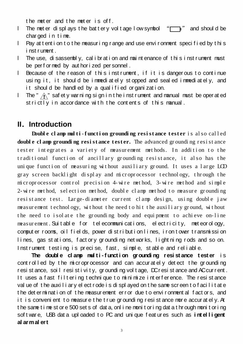
II.Introduction
Double clamp multi-function grounding resistance tester is also called
double clamp grounding resistance tester. The advanced grounding resistance
tester integrates a variety of measurement methods. In addition to the
traditional function of ancillary grounding resistance, it also has the
unique function of measuring without auxiliary ground. It uses a large LCD
gray screen backlight display and microprocessor technology, through the
microprocessor control precision 4-wire method, 3-wire method and simple
2-wire method, selection method, double clamp method to measure grounding
resistance test. Large-diameter current clamp design, using double jaw
measurement technology, without the need to hit the auxiliary ground, without
the need to isolate the grounding body and equipment to achieve on-line
measurement.Suitable for telecommunications, electricity, meteorology,
computer rooms, oil fields, power distribution lines, iron tower transmission
lines, gas stations, factory grounding networks, lightning rods and so on.
Instrument testing is precise, fast, simple, stable and reliable.
The double clamp multi-function grounding resistance tester is
controlled by the microprocessor and can accurately detect the grounding
resistance, soil resistivity, grounding voltage, DC resistance and AC current.
It uses a fast filtering technique to minimize interference. The resistance
value of the auxiliary electrode is displayed on the same screen to facilitate
the determination of the measurement error due to environmental factors, and
it is convenient to measure the true grounding resistance more accurately.At
the same time store 500 sets of data,online monitoring data through monitoring
software, USB data uploaded to PC and unique features such as intelligent
alarm alert
4
Double clamp multi-function grounding resistance tester consists of host,
monitoring software, test line, USB cable, and grounding rod. It has the
functions of reading, checking, saving, reporting and printing of historical
data.
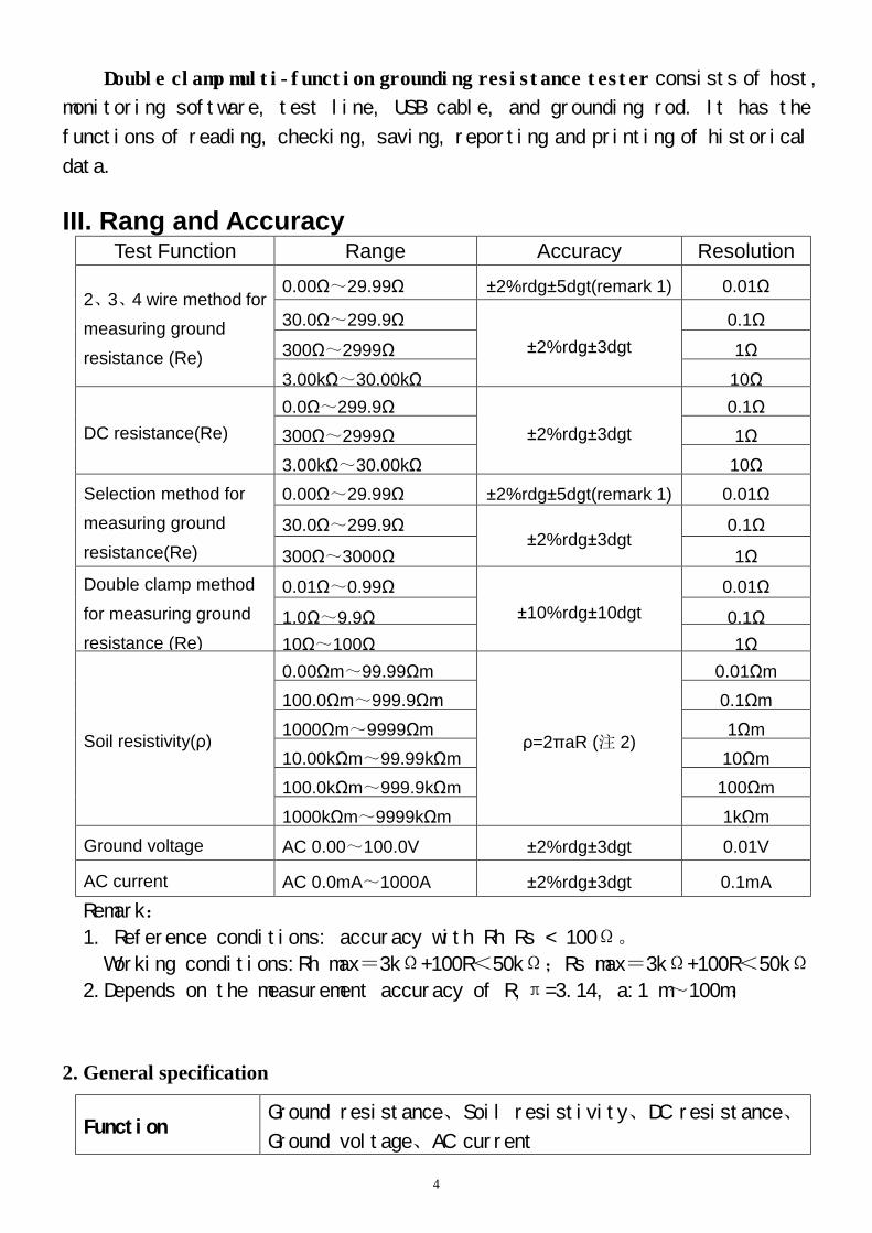
III. Rang and Accuracy Test Function Range Accuracy Resolution
2、3、4 wire method for measuring ground resistance (Re)
0.00Ω~29.99Ω ±2%rdg±5dgt(remark 1) 0.01Ω
30.0Ω~299.9Ω ±2%rdg±3dgt
0.1Ω
300Ω~2999Ω 1Ω 3.00kΩ~30.00kΩ 10Ω
DC resistance(Re) 0.0Ω~299.9Ω
±2%rdg±3dgt 0.1Ω
300Ω~2999Ω 1Ω 3.00kΩ~30.00kΩ 10Ω
Selection method for measuring ground resistance(Re)
0.00Ω~29.99Ω ±2%rdg±5dgt(remark 1) 0.01Ω
30.0Ω~299.9Ω ±2%rdg±3dgt
0.1Ω
300Ω~3000Ω 1Ω Double clamp method for measuring ground resistance (Re)
0.01Ω~0.99Ω ±10%rdg±10dgt
0.01Ω
1.0Ω~9.9Ω 0.1Ω 10Ω~100Ω 1Ω
Soil resistivity(ρ)
0.00Ωm~99.99Ωm
ρ=2πaR (注 2)
0.01Ωm 100.0Ωm~999.9Ωm 0.1Ωm 1000Ωm~9999Ωm 1Ωm 10.00kΩm~99.99kΩm 10Ωm 100.0kΩm~999.9kΩm 100Ωm 1000kΩm~9999kΩm 1kΩm
Ground voltage AC 0.00~100.0V ±2%rdg±3dgt 0.01V
AC current AC 0.0mA~1000A ±2%rdg±3dgt 0.1mA Remark:
1. Reference conditions: accuracy with Rh Rs < 100Ω。
Working conditions:Rh max=3kΩ+100R<50kΩ;Rs max=3kΩ+100R<50kΩ
2.Depends on the measurement accuracy of R,π=3.14, a:1 m~100m;
2. General specification
Function Ground resistance、Soil resistivity、DC resistance、
Ground voltage、AC current
5
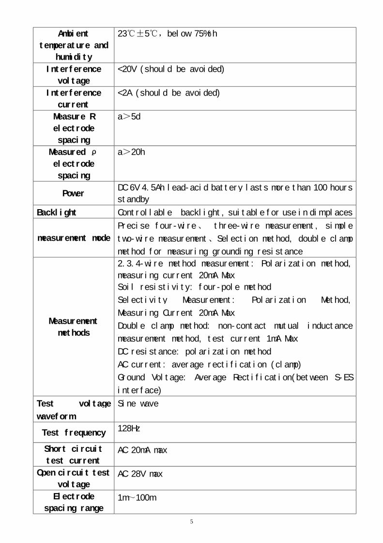
Ambient
temperature and
humidity
23℃±5℃,below 75%rh
Interference
voltage
<20V (should be avoided)
Interference
current
<2A (should be avoided)
Measure R
electrode
spacing
a>5d
Measured ρ
electrode
spacing
a>20h
Power DC 6V 4.5Ah lead-acid battery lasts more than 100 hours
standby
Backlight Controllable backlight, suitable for use in dim places
measurement mode
Precise four-wire、 three-wire measurement, simple
two-wire measurement、Selection method, double clamp
method for measuring grounding resistance
Measurement
methods
2.3.4-wire method measurement: Polarization method,
measuring current 20mA Max
Soil resistivity: four-pole method
Selectivity Measurement: Polarization Method,
Measuring Current 20mA Max
Double clamp method: non-contact mutual inductance
measurement method, test current 1mA Max
DC resistance: polarization method
AC current: average rectification (clamp)
Ground Voltage: Average Rectification(between S-ES
interface)
Test voltage
waveform
Sine wave
Test frequency 128Hz
Short circuit
test current AC 20mA max
Open circuit test
voltage AC 28V max
Electrode
spacing range 1m~100m
6
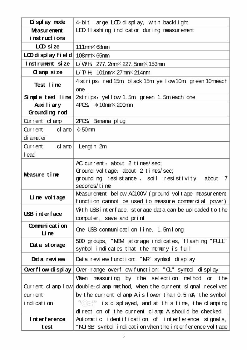
Display mode 4-bit large LCD display, with backlight
Measurement
instructions
LED flashing indicator during measurement
LCD size 111mm×68mm
LCD display field 108mm×65mm
Instrument size L/W/H:277.2mm×227.5mm×153mm
Clamp size L/T/H:101mm×27mm×214mm
Test line 4 strips:red 15m,black 15m, yellow 10m,green 10m each
one
Simple test line 2strips:yellow 1.5m,green 1.5m each one
Auxiliary
Grounding rod
4PCS:φ10mm×200mm
Current clamp 2PCS:Banana plug
Current clamp
diameter
φ50mm
Current clamp
lead
Length 2m
Measure time
AC current:about 2 times/sec;
Ground voltage:about 2 times/sec;
grounding resistance 、 soil resistivity: about 7
seconds/time
Line voltage Measurement below AC100V (ground voltage measurement
function cannot be used to measure commercial power)
USB interface With USB interface, storage data can be uploaded to the
computer, save and print
Communication
Line One USB communication line, 1.5m long
Data storage 500 groups, "MEM" storage indicates, flashing "FULL"
symbol indicates that the memory is full
Data review Data review function: "MR" symbol display
Overflow display Over-range overflow function: "OL" symbol display
Current clamp low
current
indication
When measuring by the selection method or the
double-clamp method, when the current signal received
by the current clamp A is lower than 0.5 mA, the symbol
“ ” is displayed, and at this time, the clamping
direction of the current clamp A should be checked.
Interference
test
Automatic identification of interference signals,
"NOISE" symbol indication when the interference voltage
7
is higher than 5V
Auxiliary
grounding test
With auxiliary ground resistance test function, 0.00K
Ω ~ 30kΩ (Rh max = 3kΩ +100R <50kΩ; Rs max = 3k
Ω +100R <50kΩ)
Alarm function Alarm when the measured value exceeds the alarm setting
value
Battery voltage Real-time display of battery power, reminding timely
charging when battery voltage is low
Automatic
Shutdown “APO” Indicates, automatic Shutdown After 15 Minutes
Power
consumption
Standby: 40mA Max(Backlight off)
Turn on backlight: 43mA Max
measuring:120mA Max(Backlight off)
Weight
Instrument: 2450(including battery)仪表: 2430g(含电
池)
Current clamp:940g(2PCS)
Test lines:1300g(including simple test line)
Auxiliary grounding rod: 850g(4PCS)
Working
temperature and
humidity
-10℃~40℃;below 80%rh
Storage
temperature and
humidity
-20℃~60℃;below 70%rh
Overload
protection
Grounding resistance:AC 280V/3 seconds between H-E and
S-ES ports
Insulation
resistance 20MΩ以上(500V between circuit and housing)
Pressure
resistance AC 3700V/rms(between circuit and housing)
Electromagnetic
properties IEC61326(EMC)
Suitable for
safety
regulations
IEC61010-1(CAT Ⅲ 300V、CAT IV 150V、pollution level 2);
IEC61010-031;
IEC61557-1(grounding resistance);
IEC61557-5(soil resistivity);
JJG 366-2004.
JJG 366-2004(ground resistance meter);
JJG 1054-2009(Clamp grounding resistance meter).
8
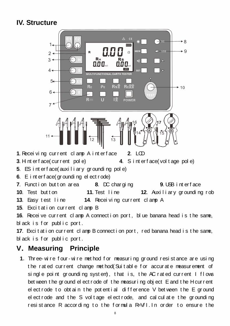
IV. Structure
1.Receiving current clamp A interface 2. LCD
3.Hinterface(current pole) 4. S interface(voltage pole)
5. ES interface(auxiliary grounding pole)
6. E interface(grounding electrode)
7. Function button area 8. DC charging 9.USB interface
10. Test button 11.Test line 12. Auxiliary grounding rob
13. Easy test line 14. Receiving current clamp A
15. Excitation current clamp B
16. Receive current clamp A connection port, blue banana head is the same,
black is for public port.
17. Excitation current clamp B connection port, red banana head is the same,
black is for public port.
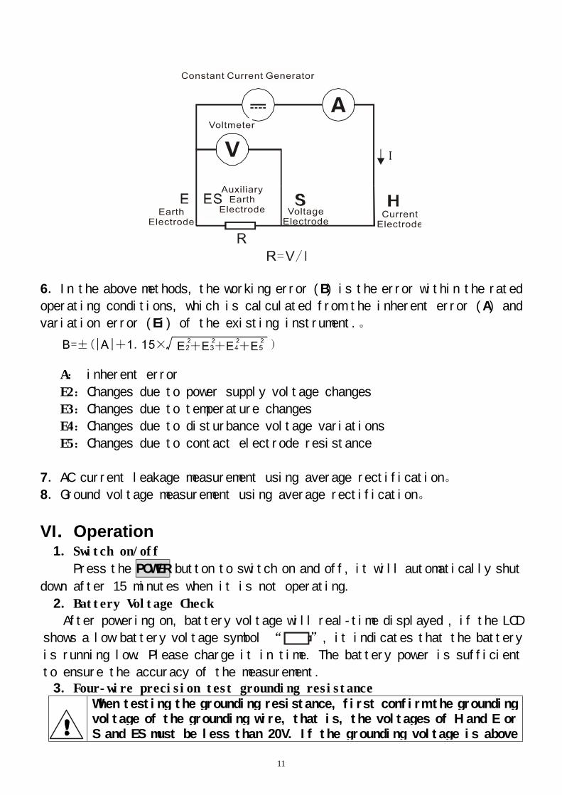
V.Measuring Principle 1.Three-wire four-wire method for measuring ground resistance are using
the rated current change method(Suitable for accurate measurement of
single point grounding system), that is, the AC rated current I flows
between the ground electrode of the measuring object E and the H current
electrode to obtain the potential difference V between the E ground
electrode and the S voltage electrode, and calculate the grounding
resistance R according to the formula R=V/I.In order to ensure the
9
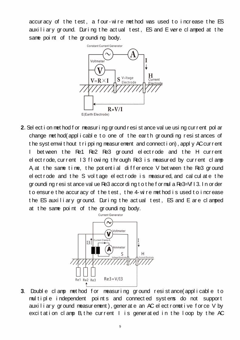
accuracy of the test, a four-wire method was used to increase the ES
auxiliary ground. During the actual test, ES and E were clamped at the
same point of the grounding body.
2.Selection method for measuring ground resistance value using current polar
change method(applicable to one of the earth grounding resistances of
the system without tripping measurement and connection),apply AC current
I between the Re1 Re2 Re3 ground electrode and the H current
electrode,current I3 flowing through Re3 is measured by current clamp
A,at the same time, the potential difference V between the Re3 ground
electrode and the S voltage electrode is measured,and calculate the
grounding resistance value Re3 according to the formula Re3=V/I3.In order
to ensure the accuracy of the test, the 4-wire method is used to increase
the ES auxiliary ground. During the actual test, ES and E are clamped
at the same point of the grounding body.
3. Double clamp method for measuring ground resistance(applicable to
multiple independent points and connected systems do not support
auxiliary ground measurement),generate an AC electromotive force V by
excitation clamp B,the current I is generated in the loop by the AC
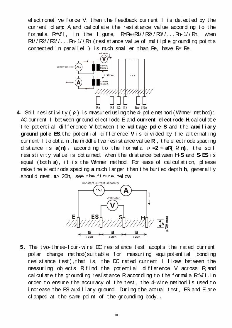
10
electromotive force V, then the feedback current I is detected by the
current clamp A,and calculate the resistance value according to the
formula R=V/I, in the figure, R=Re+R1//R2//R3//...Rn-1//Rn, when
R1//R2//R3//...Rn-1//Rn (resistance value of multiple grounding points
connected in parallel ) is much smaller than Re, have R≈Re.
4.Soil resistivity (ρ) is measured using the 4-pole method (Winner method):
AC current I between ground electrode E and current electrode H,calculate
the potential difference V between the voltage pole S and the auxiliary
ground pole ES,the potential difference V is divided by the alternating
current I to obtain the middle two resistance value R,, the electrode spacing
distance is a(m), according to the formula ρ =2π aR(Ω m), the soil
resistivity value is obtained, when the distance between H-S and S-ES is
equal (both a), it is the Wenner method. For ease of calculation, please
make the electrode spacing a much larger than the buried depth h, generally
should meet a> 20h, see the figure below.
5.The two-three-four-wire DC resistance test adopts the rated current
polar change method(suitable for measuring equipotential bonding
resistance test),that is, the DC rated current I flows between the
measuring objects R,find the potential difference V across R,and
calculate the grounding resistance R according to the formula R=V/I.In
order to ensure the accuracy of the test, the 4-wire method is used to
increase the ES auxiliary ground. During the actual test, ES and E are
clamped at the same point of the grounding body.。
11
6.In the above methods, the working error (B) is the error within the rated
operating conditions, which is calculated from the inherent error (A) and
variation error (Ei) of the existing instrument.。
A: inherent error
E2:Changes due to power supply voltage changes
E3:Changes due to temperature changes
E4:Changes due to disturbance voltage variations
E5:Changes due to contact electrode resistance
7.AC current leakage measurement using average rectification。
8.Ground voltage measurement using average rectification。
VI.Operation
1.Switch on/off
Press the POWER button to switch on and off, it will automatically shut
down after 15 minutes when it is not operating.
2.Battery Voltage Check
After powering on, battery voltage will real-time displayed , if the LCD
shows a low battery voltage symbol “ ”, it indicates that the battery
is running low. Please charge it in time. The battery power is sufficient
to ensure the accuracy of the measurement. 3.Four-wire precision test grounding resistance
When testing the grounding resistance, first confirm the grounding voltage of the grounding wire, that is, the voltages of H and E or S and ES must be less than 20V. If the grounding voltage is above
12
5V, the meter displays the NOISE symbol, then, the measurement value of the grounding resistance may be inaccurate. At this time, the measured grounding device is first de-energized so that the grounding voltage is lowered and then the grounding resistance test is performed.
Four-wire test: The four-wire test eliminates the influence of the
contact resistance between the measured grounding body, the auxiliary
grounding rod, the test clip, and the input interface of the instrument
(usually dirt or rust) on the measurement, and eliminates the wire resistance
change. The effect of the measurement is better than the three-wire test.
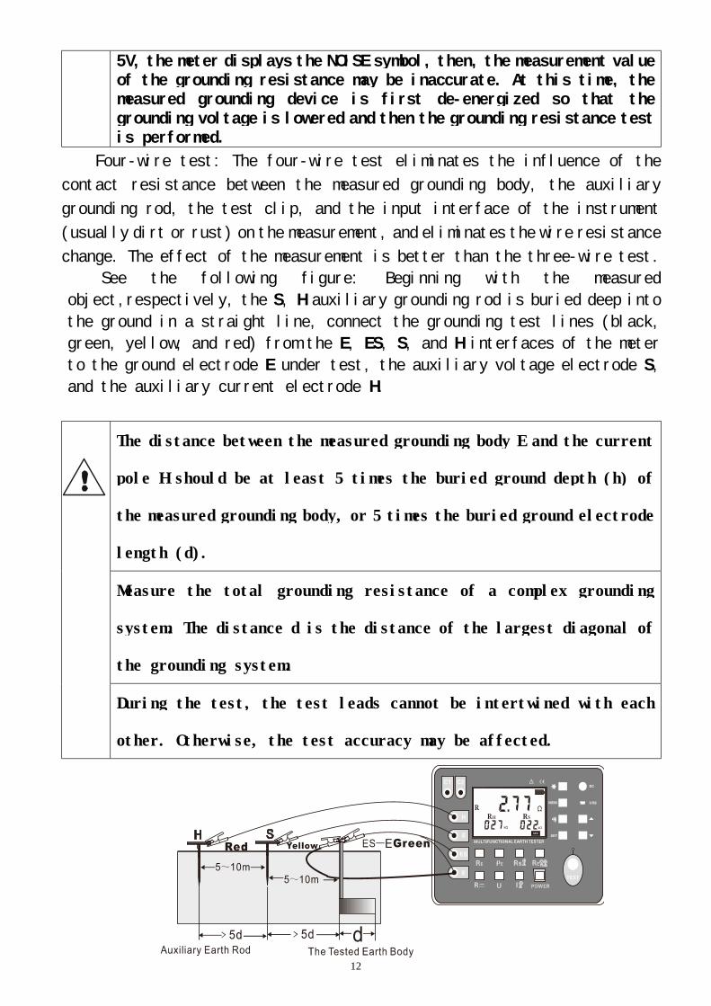
See the following figure: Beginning with the measured
object,respectively, the S, H auxiliary grounding rod is buried deep into
the ground in a straight line, connect the grounding test lines (black,
green, yellow, and red) from the E, ES, S, and H interfaces of the meter
to the ground electrode E under test, the auxiliary voltage electrode S,
and the auxiliary current electrode H.
The distance between the measured grounding body E and the current
pole H should be at least 5 times the buried ground depth (h) of
the measured grounding body, or 5 times the buried ground electrode
length (d).
Measure the total grounding resistance of a complex grounding
system. The distance d is the distance of the largest diagonal of
the grounding system.
During the test, the test leads cannot be intertwined with each
other. Otherwise, the test accuracy may be affected.
13
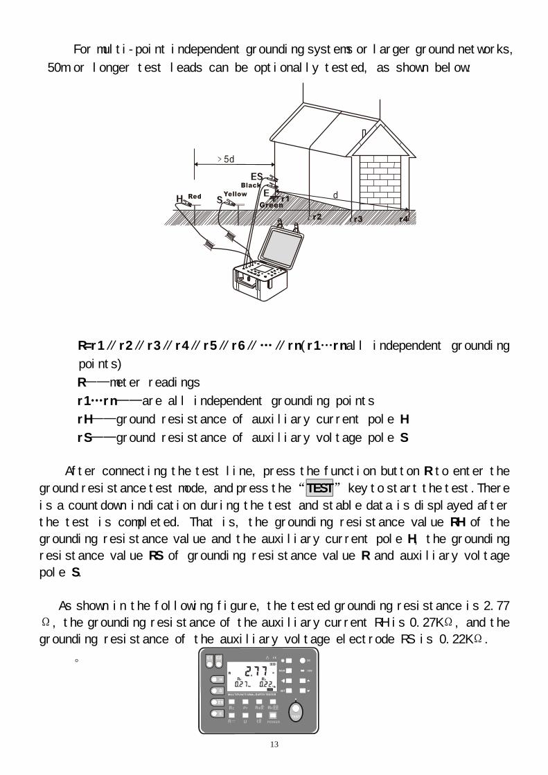
For multi-point independent grounding systems or larger ground networks,
50m or longer test leads can be optionally tested, as shown below:
R=r1∥r2∥r3∥r4∥r5∥r6∥…∥rn(r1…rnall independent grounding
points)
R——meter readings
r1…rn——are all independent grounding points
rH——ground resistance of auxiliary current pole H
rS——ground resistance of auxiliary voltage pole S
After connecting the test line, press the function button R to enter the
ground resistance test mode, and press the “TEST” key to start the test.There
is a countdown indication during the test and stable data is displayed after
the test is completed. That is, the grounding resistance value RH of the
grounding resistance value and the auxiliary current pole H, the grounding
resistance value RS of grounding resistance value R and auxiliary voltage
pole S.
As shown in the following figure, the tested grounding resistance is 2.77
Ω, the grounding resistance of the auxiliary current RH is 0.27KΩ, and the
grounding resistance of the auxiliary voltage electrode RS is 0.22KΩ.
。
14
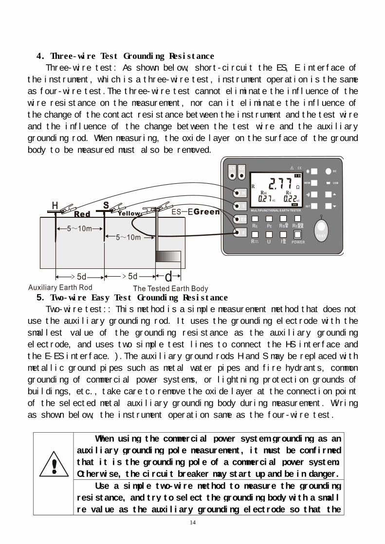
4.Three-wire Test Grounding Resistance
Three-wire test: As shown below, short-circuit the ES, E interface of
the instrument, which is a three-wire test, instrument operation is the same
as four-wire test.The three-wire test cannot eliminate the influence of the
wire resistance on the measurement, nor can it eliminate the influence of
the change of the contact resistance between the instrument and the test wire
and the influence of the change between the test wire and the auxiliary
grounding rod. When measuring, the oxide layer on the surface of the ground
body to be measured must also be removed.
5.Two-wire Easy Test Grounding Resistance
Two-wire test:: This method is a simple measurement method that does not
use the auxiliary grounding rod. It uses the grounding electrode with the
smallest value of the grounding resistance as the auxiliary grounding
electrode, and uses two simple test lines to connect the HS interface and
the E-ES interface. ).The auxiliary ground rods H and S may be replaced with
metallic ground pipes such as metal water pipes and fire hydrants, common
grounding of commercial power systems, or lightning protection grounds of
buildings, etc., take care to remove the oxide layer at the connection point
of the selected metal auxiliary grounding body during measurement. Wiring
as shown below, the instrument operation same as the four-wire test.
When using the commercial power system grounding as an
auxiliary grounding pole measurement, it must be confirmed
that it is the grounding pole of a commercial power system.
Otherwise, the circuit breaker may start up and be in danger.
Use a simple two-wire method to measure the grounding
resistance, and try to select the grounding body with a small
re value as the auxiliary grounding electrode so that the
15
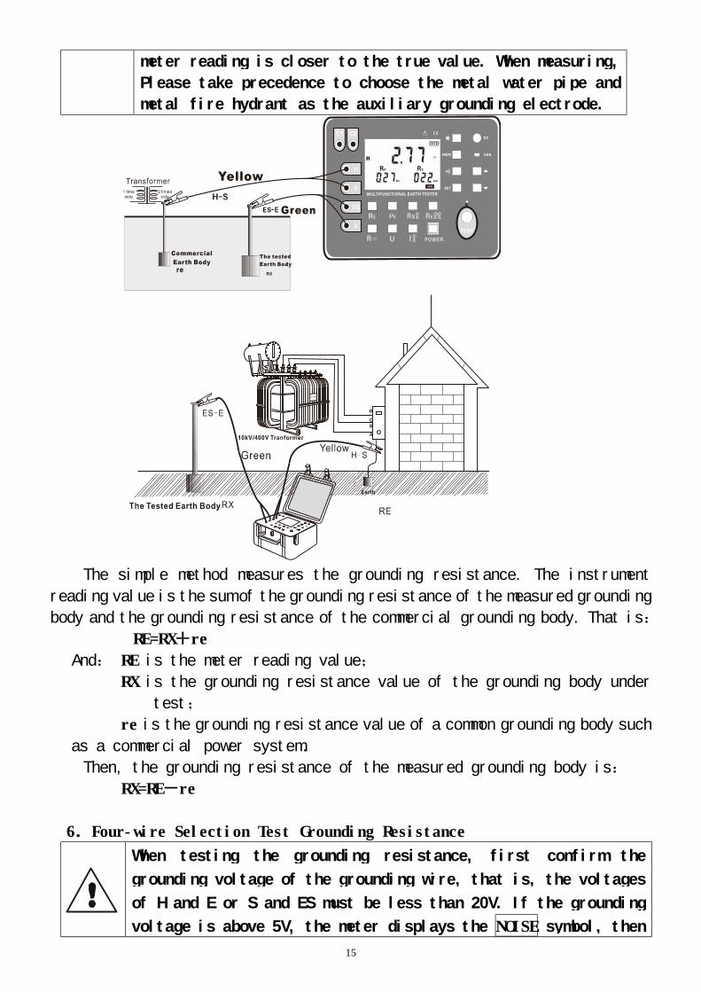
meter reading is closer to the true value. When measuring,
Please take precedence to choose the metal water pipe and
metal fire hydrant as the auxiliary grounding electrode.
The simple method measures the grounding resistance. The instrument
reading value is the sum of the grounding resistance of the measured grounding
body and the grounding resistance of the commercial grounding body. That is:
RE=RX+re
And: RE is the meter reading value;
RX is the grounding resistance value of the grounding body under
test;
re is the grounding resistance value of a common grounding body such
as a commercial power system.
Then, the grounding resistance of the measured grounding body is:
RX=RE-re
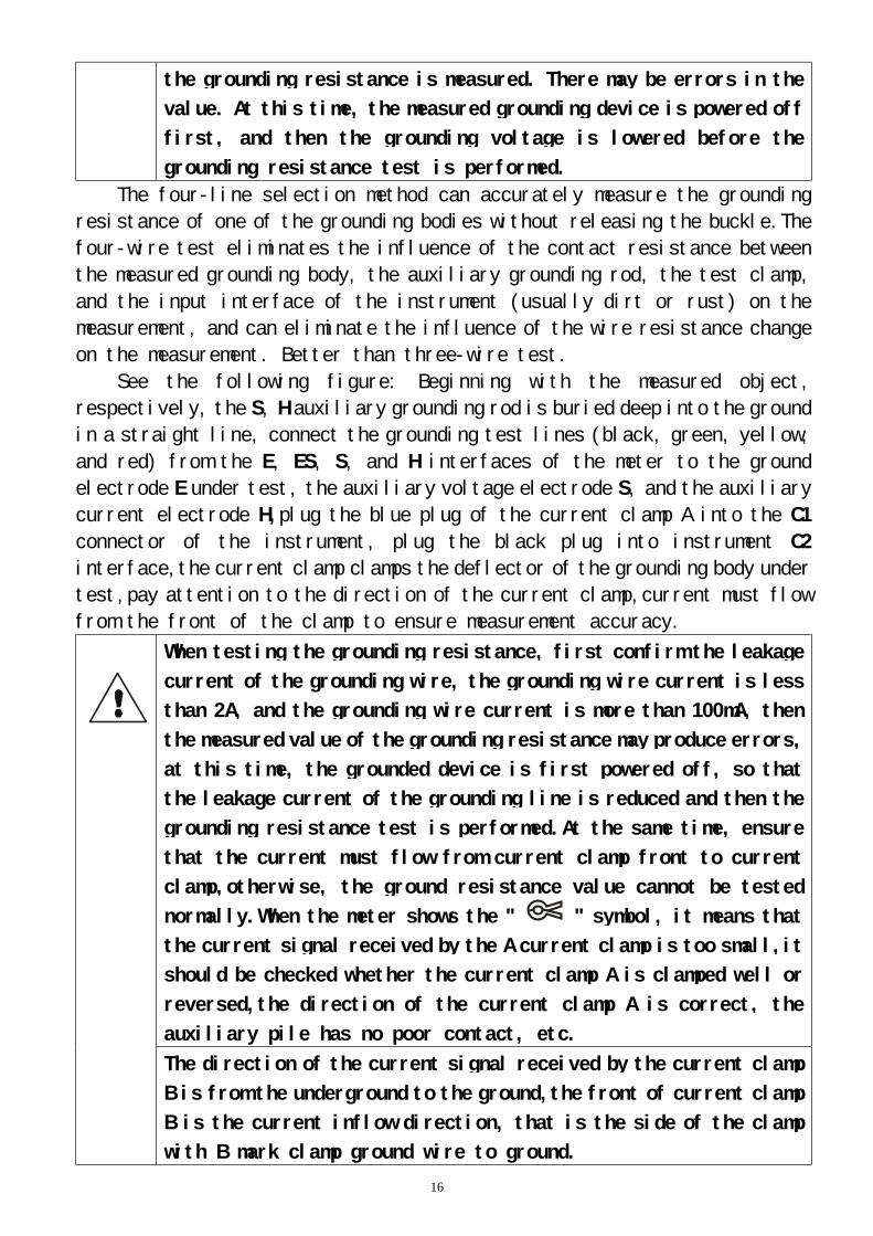
6.Four-wire Selection Test Grounding Resistance
When testing the grounding resistance, first confirm the
grounding voltage of the grounding wire, that is, the voltages
of H and E or S and ES must be less than 20V. If the grounding
voltage is above 5V, the meter displays the NOISE symbol, then
16
the grounding resistance is measured. There may be errors in the
value. At this time, the measured grounding device is powered off
first, and then the grounding voltage is lowered before the
grounding resistance test is performed.
The four-line selection method can accurately measure the grounding
resistance of one of the grounding bodies without releasing the buckle.The
four-wire test eliminates the influence of the contact resistance between
the measured grounding body, the auxiliary grounding rod, the test clamp,
and the input interface of the instrument (usually dirt or rust) on the
measurement, and can eliminate the influence of the wire resistance change
on the measurement. Better than three-wire test.
See the following figure: Beginning with the measured object,
respectively, the S, H auxiliary grounding rod is buried deep into the ground
in a straight line, connect the grounding test lines (black, green, yellow,
and red) from the E, ES, S, and H interfaces of the meter to the ground
electrode E under test, the auxiliary voltage electrode S, and the auxiliary
current electrode H,plug the blue plug of the current clamp A into the C1
connector of the instrument, plug the black plug into instrument C2
interface,the current clamp clamps the deflector of the grounding body under
test,pay attention to the direction of the current clamp,current must flow
from the front of the clamp to ensure measurement accuracy.
When testing the grounding resistance, first confirm the leakage
current of the grounding wire, the grounding wire current is less
than 2A, and the grounding wire current is more than 100mA, then
the measured value of the grounding resistance may produce errors,
at this time, the grounded device is first powered off, so that
the leakage current of the grounding line is reduced and then the
grounding resistance test is performed.At the same time, ensure
that the current must flow from current clamp front to current
clamp,otherwise, the ground resistance value cannot be tested
normally.When the meter shows the " " symbol, it means that
the current signal received by the A current clamp is too small,it
should be checked whether the current clamp A is clamped well or
reversed,the direction of the current clamp A is correct, the
auxiliary pile has no poor contact, etc.
The direction of the current signal received by the current clamp
B is from the underground to the ground,the front of current clamp
B is the current inflow direction, that is the side of the clamp
with B mark clamp ground wire to ground.
17
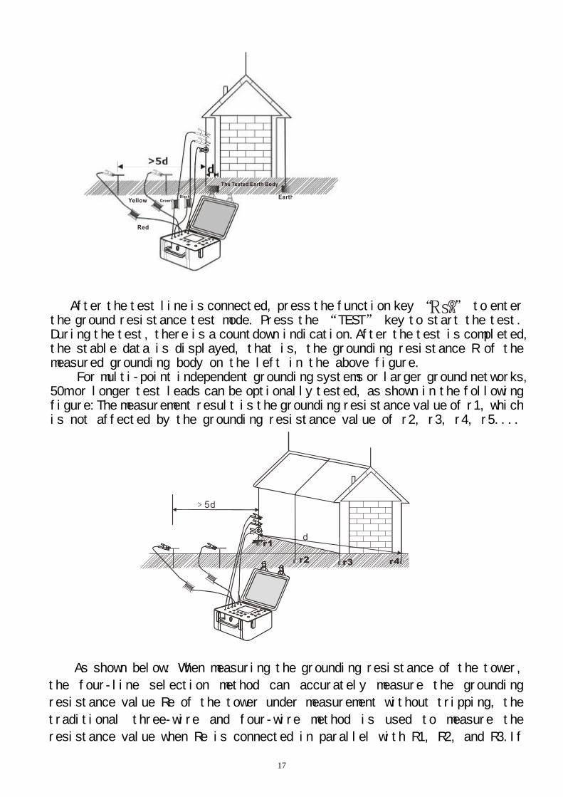
After the test line is connected, press the function key “ ” to enter the ground resistance test mode. Press the “TEST” key to start the test. During the test, there is a countdown indication.After the test is completed, the stable data is displayed, that is, the grounding resistance R of the measured grounding body on the left in the above figure.
For multi-point independent grounding systems or larger ground networks, 50m or longer test leads can be optionally tested, as shown in the following figure:The measurement result is the grounding resistance value of r1, which is not affected by the grounding resistance value of r2, r3, r4, r5....
As shown below: When measuring the grounding resistance of the tower,
the four-line selection method can accurately measure the grounding
resistance value Re of the tower under measurement without tripping, the
traditional three-wire and four-wire method is used to measure the
resistance value when Re is connected in parallel with R1, R2, and R3.If
18
Re is faulty and R1, R2, and R3 are connected in parallel, the traditional
three-wire and four-wire method is difficult to find out where the Re fault
is located,easily overlooked.
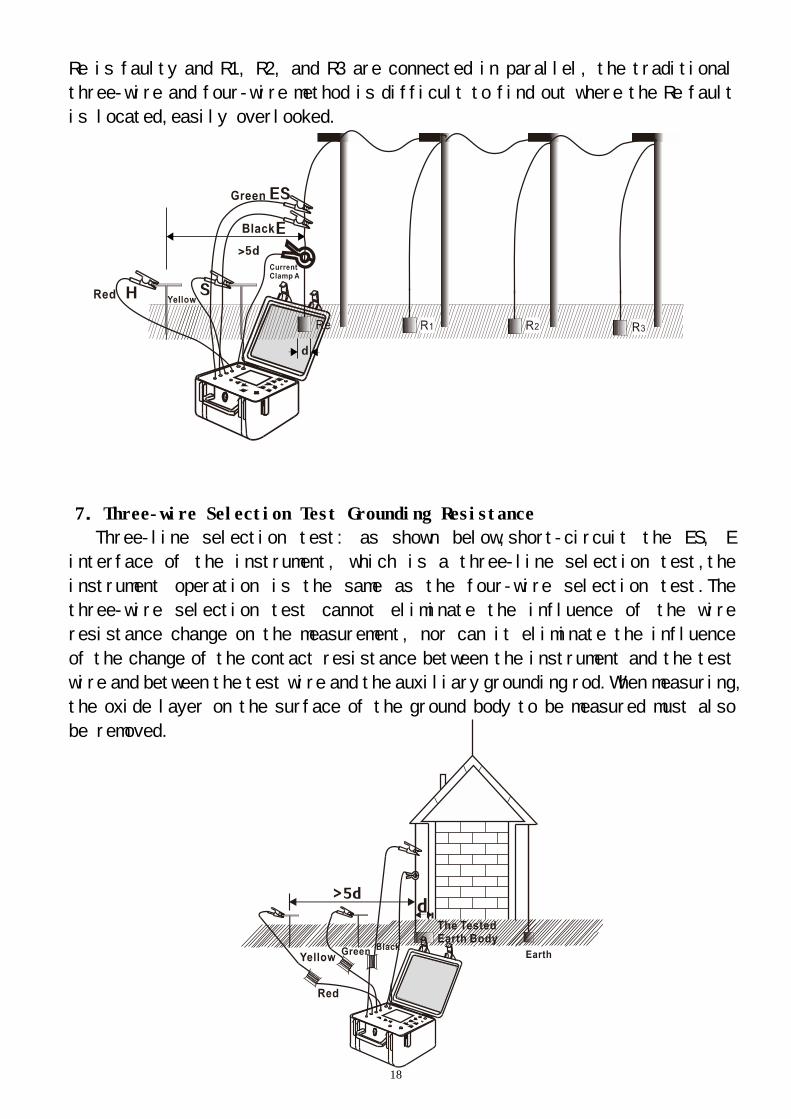
7.Three-wire Selection Test Grounding Resistance
Three-line selection test: as shown below,short-circuit the ES, E
interface of the instrument, which is a three-line selection test,the
instrument operation is the same as the four-wire selection test.The
three-wire selection test cannot eliminate the influence of the wire
resistance change on the measurement, nor can it eliminate the influence
of the change of the contact resistance between the instrument and the test
wire and between the test wire and the auxiliary grounding rod.When measuring,
the oxide layer on the surface of the ground body to be measured must also
be removed.
19
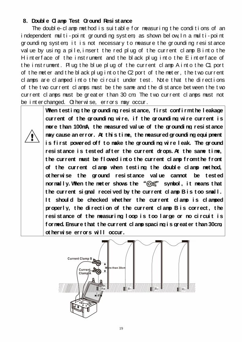
8.Double Clamp Test Ground Resistance
The double-clamp method is suitable for measuring the conditions of an
independent multi-point grounding system, as shown below,In a multi-point
grounding system, it is not necessary to measure the grounding resistance
value by using a pile,insert the red plug of the current clamp B into the
H interface of the instrument and the black plug into the E interface of
the instrument. Plug the blue plug of the current clamp A into the C1 port
of the meter and the black plug into the C2 port of the meter, the two current
clamps are clamped into the circuit under test. Note that the directions
of the two current clamps must be the same and the distance between the two
current clamps must be greater than 30 cm. The two current clamps must not
be interchanged. Otherwise, errors may occur. When testing the grounding resistance, first confirm the leakage
current of the grounding wire, if the grounding wire current is
more than 100mA, the measured value of the grounding resistance
may cause an error. At this time, the measured grounding equipment
is first powered off to make the grounding wire leak. The ground
resistance is tested after the current drops.At the same time,
the current must be flowed into the current clamp from the front
of the current clamp when testing the double clamp method,
otherwise the ground resistance value cannot be tested
normally.When the meter shows the “ ” symbol, it means that
the current signal received by the current clamp B is too small.
It should be checked whether the current clamp is clamped
properly, the direction of the current clamp B is correct, the
resistance of the measuring loop is too large or no circuit is
formed.Ensure that the current clamp spacing is greater than 30cm,
otherwise errors will occur.
20
After the test line is connected, turn the function selection knob to
the “ ” position to enter the ground resistance test mode. Press the
“TEST” key to start the test. During the test, there is a countdown
indication and a test progress bar graph indicator. After the test is
completed, stable data is displayed, That is, the measured grounding
resistance of the grounding body R=Re+R1//R2//R3. When R1//R2//R3<<Re, it
can be approximated as R≈Re.
9.Soil Resistivity Test
The soil resistivity ρ is an important factor that determines the
grounding resistance of the grounding body.The soil resistivity ρ is an
important factor determining the grounding resistance of the grounding
body.Different types of soil, of course, have different soil resistivities,
even the same kind of soil, because of different temperature and moisture
content, the soil resistivity will also have a significant change.Therefore,
in order to have a correct basis for the design of the grounding device, the
designed grounding device can better meet the needs of the actual work, and
the soil resistivity must be measured.
The soil resistivity was measured by the four-pole method (Winner
method).
The soil resistivity ρ is calculated according to the formula ρ=2π
aR (Ωm), and the unit is Ωm, and:
a——Electrode spacing
R——S-ES Resistance of soil between electrodes
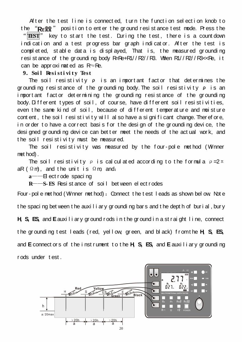
Four-pole method (Winner method):Connect the test leads as shown below. Note
the spacing between the auxiliary grounding bars and the depth of burial,bury
H, S, ES, and E auxiliary ground rods in the ground in a straight line, connect
the grounding test leads (red, yellow, green, and black) from the H, S, ES,
and E connectors of the instrument to the H, S, ES, and E auxiliary grounding
rods under test.
21
According to the Wenner method, the value of the soil resistivity measured
is approximately the soil resistivity at the depth a between the two grounding
rods. The soil homogeneity can be checked by changing the a value to design
a suitable grounding electrode.
Auxiliary ground rod spacing setting:After connecting the test line,
press the function button“ ”to enter the soil resistivity test mode,
press and hold the “SET” key (more than 3 seconds) to enter the spacing
setting of the auxiliary grounding rod, short press " " to move the cursor,
press " " or " " key to change the current value (value a range: 1m ~
100m), long press "SET" key (more than 3 seconds) to save the set value a
and return to soil resistivity test mode.
After setting value a, in soil resistivity test mode, press “TEST” key
to start the test, and count down to display the test progress. After the
test is completed, a stable soil resistivity value is displayed.
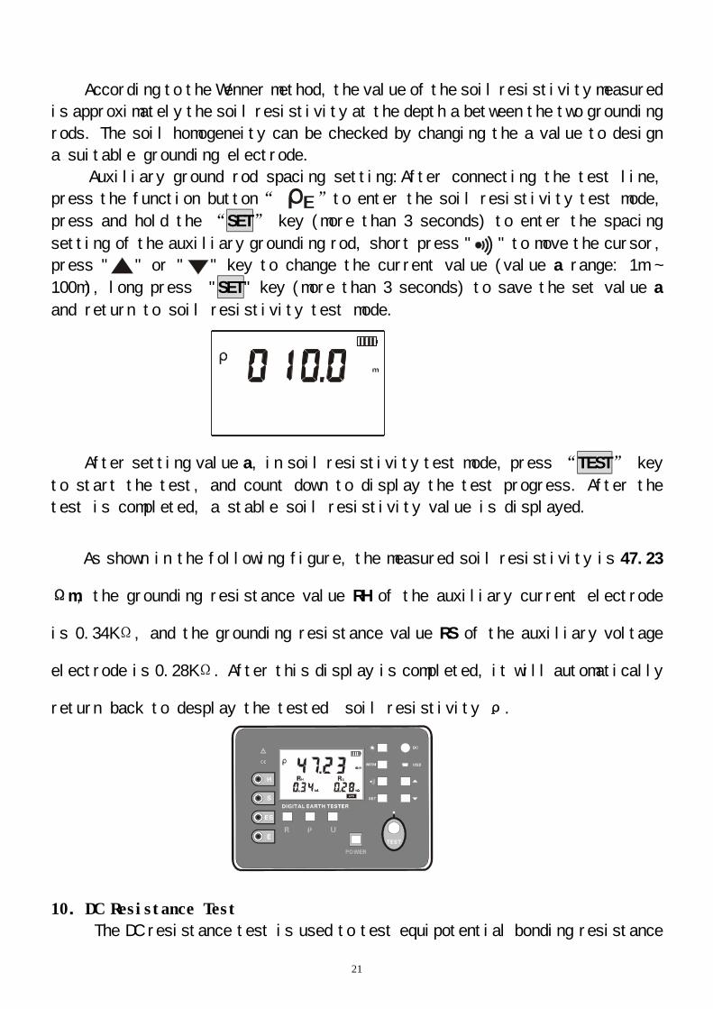
As shown in the following figure, the measured soil resistivity is 47.23
Ωm, the grounding resistance value RH of the auxiliary current electrode
is 0.34KΩ, and the grounding resistance value RS of the auxiliary voltage
electrode is 0.28KΩ. After this display is completed, it will automatically
return back to desplay the tested soil resistivity ρ.
10.DC Resistance Test
The DC resistance test is used to test equipotential bonding resistance
22
and resistance between metal components. The four-wire test can eliminate
the influence of the contact resistance between the test clamp and the input
interface of the instrument (usually dirt or rust) on the measurement,it
can eliminate the impact of line resistance change on the measurement, better
than the two-wire test.
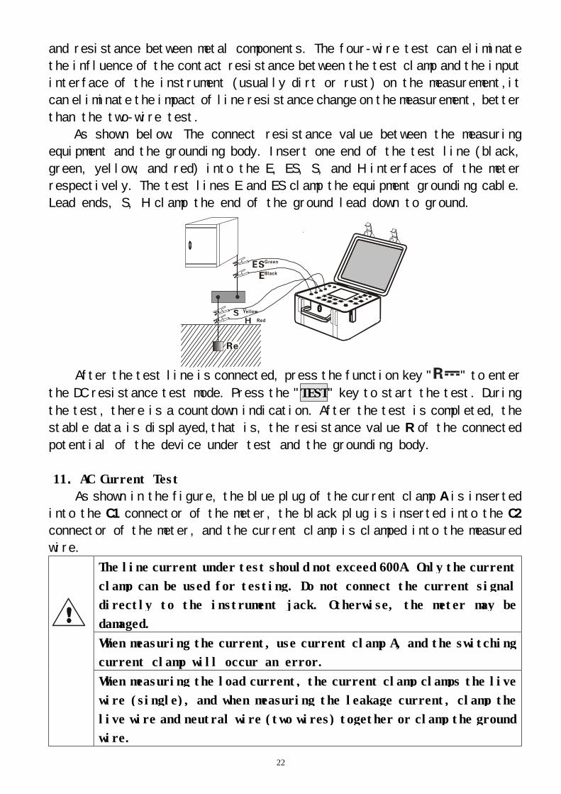
As shown below: The connect resistance value between the measuring
equipment and the grounding body. Insert one end of the test line (black,
green, yellow, and red) into the E, ES, S, and H interfaces of the meter
respectively. The test lines E and ES clamp the equipment grounding cable.
Lead ends, S, H clamp the end of the ground lead down to ground.
After the test line is connected, press the function key " " to enter
the DC resistance test mode. Press the "TEST" key to start the test. During
the test, there is a countdown indication. After the test is completed, the
stable data is displayed,that is, the resistance value R of the connected
potential of the device under test and the grounding body.
11.AC Current Test
As shown in the figure, the blue plug of the current clamp A is inserted
into the C1 connector of the meter, the black plug is inserted into the C2
connector of the meter, and the current clamp is clamped into the measured
wire.
The line current under test should not exceed 600A. Only the current
clamp can be used for testing. Do not connect the current signal
directly to the instrument jack. Otherwise, the meter may be
damaged.
When measuring the current, use current clamp A, and the switching
current clamp will occur an error.
When measuring the load current, the current clamp clamps the live
wire (single), and when measuring the leakage current, clamp the
live wire and neutral wire (two wires) together or clamp the ground
wire.
23
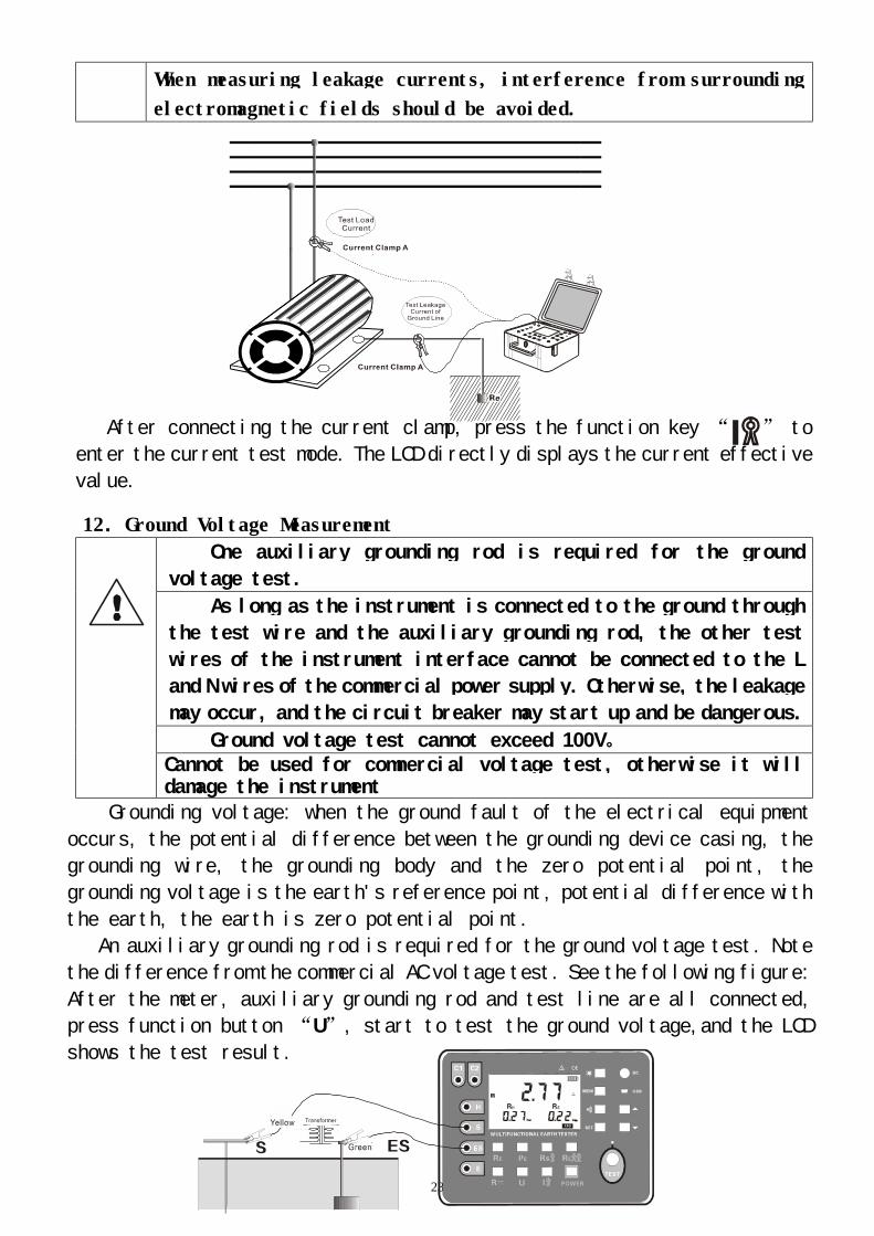
When measuring leakage currents, interference from surrounding
electromagnetic fields should be avoided.
After connecting the current clamp, press the function key “ ” to
enter the current test mode. The LCD directly displays the current effective
value.
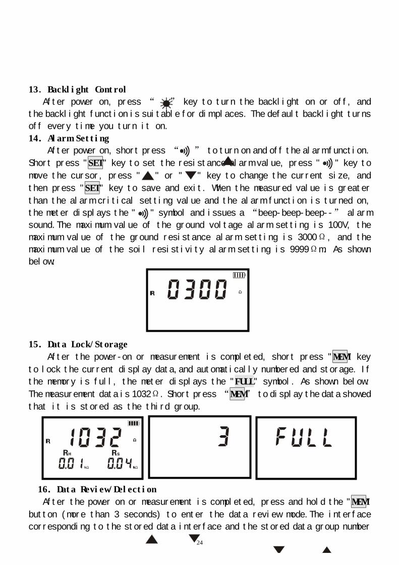
12.Ground Voltage Measurement One auxiliary grounding rod is required for the ground
voltage test.
As long as the instrument is connected to the ground through
the test wire and the auxiliary grounding rod, the other test
wires of the instrument interface cannot be connected to the L
and N wires of the commercial power supply. Otherwise, the leakage
may occur, and the circuit breaker may start up and be dangerous.
Ground voltage test cannot exceed 100V。 Cannot be used for commercial voltage test, otherwise it will damage the instrument
Grounding voltage: when the ground fault of the electrical equipment
occurs, the potential difference between the grounding device casing, the
grounding wire, the grounding body and the zero potential point, the
grounding voltage is the earth's reference point, potential difference with
the earth, the earth is zero potential point.
An auxiliary grounding rod is required for the ground voltage test. Note
the difference from the commercial AC voltage test. See the following figure:
After the meter, auxiliary grounding rod and test line are all connected,
press function button “U”, start to test the ground voltage,and the LCD
shows the test result.
24
13.Backlight Control
After power on, press “ ” key to turn the backlight on or off, and
the backlight function is suitable for dim places. The default backlight turns
off every time you turn it on.
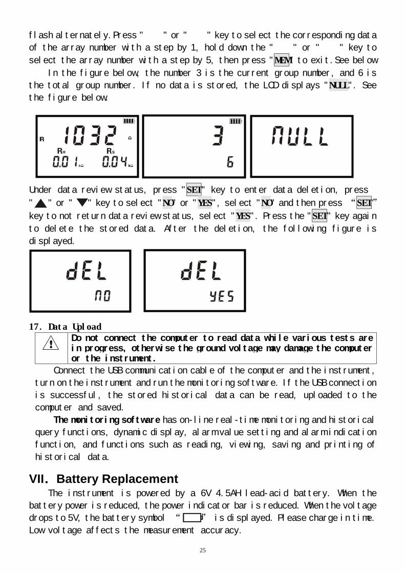
14.Alarm Setting
After power on, short press “ ” to turn on and off the alarm function.
Short press "SET" key to set the resistance alarm value, press " " key to
move the cursor, press " " or " " key to change the current size, and
then press "SET" key to save and exit. When the measured value is greater
than the alarm critical setting value and the alarm function is turned on,
the meter displays the " " symbol and issues a “beep-beep-beep--” alarm
sound.The maximum value of the ground voltage alarm setting is 100V, the
maximum value of the ground resistance alarm setting is 3000Ω, and the
maximum value of the soil resistivity alarm setting is 9999Ωm. As shown
below:
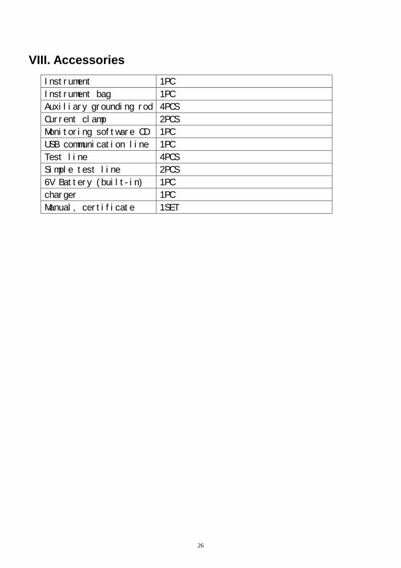
15.Data Lock/Storage
After the power-on or measurement is completed, short press "MEM" key
to lock the current display data,and automatically numbered and storage. If
the memory is full, the meter displays the "FULL" symbol. As shown below:
The measurement data is 1032Ω. Short press “MEM” to display the data showed
that it is stored as the third group.
16.Data Review/Delection
After the power on or measurement is completed, press and hold the "MEM"
button (more than 3 seconds) to enter the data review mode.The interface
corresponding to the stored data interface and the stored data group number
25
flash alternately.Press " " or " " key to select the corresponding data
of the array number with a step by 1, hold down the " " or " " key to
select the array number with a step by 5, then press "MEM" to exit.See below
In the figure below, the number 3 is the current group number, and 6 is
the total group number. If no data is stored, the LCD displays "NULL". See
the figure below.
Under data review status, press "SET" key to enter data deletion, press
" " or " " key to select "NO" or "YES", select "NO" and then press “SET”
key to not return data review status, select "YES". Press the "SET" key again
to delete the stored data. After the deletion, the following figure is
displayed.
17.Data Upload Do not connect the computer to read data while various tests are
in progress, otherwise the ground voltage may damage the computer or the instrument.
Connect the USB communication cable of the computer and the instrument,
turn on the instrument and run the monitoring software. If the USB connection
is successful, the stored historical data can be read, uploaded to the
computer and saved.
The monitoring software has on-line real-time monitoring and historical
query functions, dynamic display, alarm value setting and alarm indication
function, and functions such as reading, viewing, saving and printing of
historical data.
VII.Battery Replacement The instrument is powered by a 6V 4.5AH lead-acid battery. When the
battery power is reduced, the power indicator bar is reduced. When the voltage
drops to 5V, the battery symbol “ ” is displayed. Please charge in time.
Low voltage affects the measurement accuracy.
26
VIII. Accessories
Instrument 1PC
Instrument bag 1PC
Auxiliary grounding rod 4PCS
Current clamp 2PCS
Monitoring software CD 1PC
USB communication line 1PC
Test line 4PCS
Simple test line 2PCS
6V Battery (built-in) 1PC
charger 1PC
Manual, certificate 1SET
27
The contents of this user manual cannot be used as a reason to use the product for special purposes. The company is not responsible for other losses caused by use. The company reserves the right to modify the contents of the user manual. If there is any change, it will not be notified.
GuangZhou ZhengNeng Electronics Technology Co. Address: 2F, No.15 Baoshu Road, Taihe, Baiyun District, Guangzhou, Guangdong, China Toll-free call:4000-1515-38
Tel:86-20-36544172
Fax:86-20-37319075
Post:510540
WebSite:www.znele.com