Embed Size (px)
Citation preview

ES5340.2 Internal Combustion Engine ApplicationUser’s Guide
2
Copyright
The data in this document may not be altered or amended without special noti-fication from ETAS GmbH. ETAS GmbH undertakes no further obligation in rela-tion to this document. The software described in it can only be used if thecustomer is in possession of a general license agreement or single license. Usingand copying is only allowed in concurrence with the specifications stipulated inthe contract.
Under no circumstances may any part of this document be copied, reproduced,transmitted, stored in a retrieval system or translated into another languagewithout the express written permission of ETAS GmbH.
© Copyright 2014-2017 ETAS GmbH, Stuttgart
The names and designations used in this document are trademarks or brandsbelonging to the respective owners.
V1.0.0 R04 EN - 06.2017

Contents
ETAS Contents
1 Introduction . . . . . . . . . . . . . . . . . . . . . . . . . . . . . . . . . . . . . . . . . . . . . . . . . . . . . . 51.1 Features . . . . . . . . . . . . . . . . . . . . . . . . . . . . . . . . . . . . . . . . . . . . . . . . . . . . 5
1.1.1 Analog and Digital Inputs and Outputs . . . . . . . . . . . . . . . . . . . . . . 51.1.2 Measuring Signals . . . . . . . . . . . . . . . . . . . . . . . . . . . . . . . . . . . . . . 51.1.3 Generation of Arbitrary Signals . . . . . . . . . . . . . . . . . . . . . . . . . . . . 5
1.2 Basic Safety Instructions . . . . . . . . . . . . . . . . . . . . . . . . . . . . . . . . . . . . . . . . 71.2.1 Labeling of Safety Instructions . . . . . . . . . . . . . . . . . . . . . . . . . . . . . 71.2.2 General Safety Information . . . . . . . . . . . . . . . . . . . . . . . . . . . . . . . 71.2.3 Connecting/Removing Devices. . . . . . . . . . . . . . . . . . . . . . . . . . . . . 71.2.4 Requirements made of the User and Obligations of the Operator . . 8
1.3 Identifications on the Product . . . . . . . . . . . . . . . . . . . . . . . . . . . . . . . . . . . . 91.4 CE Marking . . . . . . . . . . . . . . . . . . . . . . . . . . . . . . . . . . . . . . . . . . . . . . . . . 91.5 RoHS Conformity . . . . . . . . . . . . . . . . . . . . . . . . . . . . . . . . . . . . . . . . . . . . . 9
1.5.1 European Union . . . . . . . . . . . . . . . . . . . . . . . . . . . . . . . . . . . . . . . 91.5.2 China . . . . . . . . . . . . . . . . . . . . . . . . . . . . . . . . . . . . . . . . . . . . . . . 9
1.6 Taking the Product Back and Recycling . . . . . . . . . . . . . . . . . . . . . . . . . . . . 101.7 About This Manual . . . . . . . . . . . . . . . . . . . . . . . . . . . . . . . . . . . . . . . . . . . 11
1.7.1 Using This Manual . . . . . . . . . . . . . . . . . . . . . . . . . . . . . . . . . . . . . 11
2 Installation and Configuration. . . . . . . . . . . . . . . . . . . . . . . . . . . . . . . . . . . . . . . . 132.1 Installing the ES5340.2-ICE in the Real-Time PC . . . . . . . . . . . . . . . . . . . . . 13
2.1.1 Requirements and Specifications . . . . . . . . . . . . . . . . . . . . . . . . . . 132.1.2 Installation . . . . . . . . . . . . . . . . . . . . . . . . . . . . . . . . . . . . . . . . . . 14
2.2 Installing the ES5340.2-ICE in the ES5300.1-A Housing . . . . . . . . . . . . . . . 142.3 RPM Master/Slave Configuration . . . . . . . . . . . . . . . . . . . . . . . . . . . . . . . . . 14
2.3.1 Connecting the RPM Buses of Two Boards . . . . . . . . . . . . . . . . . . . 142.3.2 Configuration of the RPM Unit (in LABCAR-RTC) . . . . . . . . . . . . . . 15
ES5340.2 Internal Combustion Engine Application - User’s Guide 3
4
Contents ETAS
3 Hardware Description . . . . . . . . . . . . . . . . . . . . . . . . . . . . . . . . . . . . . . . . . . . . . . 173.1 Generating Analog Signals . . . . . . . . . . . . . . . . . . . . . . . . . . . . . . . . . . . . . 18
3.1.1 Specification . . . . . . . . . . . . . . . . . . . . . . . . . . . . . . . . . . . . . . . . . 183.1.2 Configuring the Analog Signals . . . . . . . . . . . . . . . . . . . . . . . . . . . 19
3.2 Output Multiplexers for the Analog Signals . . . . . . . . . . . . . . . . . . . . . . . . . 203.3 Generating Digital Signals . . . . . . . . . . . . . . . . . . . . . . . . . . . . . . . . . . . . . . 21
3.3.1 Specification . . . . . . . . . . . . . . . . . . . . . . . . . . . . . . . . . . . . . . . . . 213.3.2 Configuring the Digital Signals . . . . . . . . . . . . . . . . . . . . . . . . . . . 21
3.4 Output Multiplexers for the Digital Signals . . . . . . . . . . . . . . . . . . . . . . . . . 223.5 Analog Inputs . . . . . . . . . . . . . . . . . . . . . . . . . . . . . . . . . . . . . . . . . . . . . . . 23
3.5.1 Specification . . . . . . . . . . . . . . . . . . . . . . . . . . . . . . . . . . . . . . . . . 233.5.2 Configuring the Analog Inputs . . . . . . . . . . . . . . . . . . . . . . . . . . . 23
3.6 Digital Inputs . . . . . . . . . . . . . . . . . . . . . . . . . . . . . . . . . . . . . . . . . . . . . . . 243.6.1 Specification . . . . . . . . . . . . . . . . . . . . . . . . . . . . . . . . . . . . . . . . . 243.6.2 Threshold Comparison. . . . . . . . . . . . . . . . . . . . . . . . . . . . . . . . . . 243.6.3 Configuring the Digital Inputs . . . . . . . . . . . . . . . . . . . . . . . . . . . . 253.6.4 Measurement Modes. . . . . . . . . . . . . . . . . . . . . . . . . . . . . . . . . . . 253.6.5 Rail Pressure Measurements. . . . . . . . . . . . . . . . . . . . . . . . . . . . . . 26
3.7 Arbitrary Signal Generators . . . . . . . . . . . . . . . . . . . . . . . . . . . . . . . . . . . . . 283.7.1 RPM Generator . . . . . . . . . . . . . . . . . . . . . . . . . . . . . . . . . . . . . . . 283.7.2 Waveform Pool for Signal Generators . . . . . . . . . . . . . . . . . . . . . . 283.7.3 Knock Signal Generator. . . . . . . . . . . . . . . . . . . . . . . . . . . . . . . . . 293.7.4 Misfire Control . . . . . . . . . . . . . . . . . . . . . . . . . . . . . . . . . . . . . . . 303.7.5 Sequence Tables . . . . . . . . . . . . . . . . . . . . . . . . . . . . . . . . . . . . . . 303.7.6 MSA Sensor . . . . . . . . . . . . . . . . . . . . . . . . . . . . . . . . . . . . . . . . . 31
3.8 RPM Generator . . . . . . . . . . . . . . . . . . . . . . . . . . . . . . . . . . . . . . . . . . . . . . 313.8.1 Angle Clock Signal . . . . . . . . . . . . . . . . . . . . . . . . . . . . . . . . . . . . 313.8.2 Synchronization. . . . . . . . . . . . . . . . . . . . . . . . . . . . . . . . . . . . . . . 323.8.3 Configuring the RPM Unit in LABCAR-RTC . . . . . . . . . . . . . . . . . . 33
4 Connector Assignment and Display Elements . . . . . . . . . . . . . . . . . . . . . . . . . . . . 354.1 Connector Assignment . . . . . . . . . . . . . . . . . . . . . . . . . . . . . . . . . . . . . . . . 36
4.1.1 Connector for the Outputs . . . . . . . . . . . . . . . . . . . . . . . . . . . . . . 364.1.2 Connector for the Inputs . . . . . . . . . . . . . . . . . . . . . . . . . . . . . . . . 374.1.3 Connector for the Angle Clock Signal . . . . . . . . . . . . . . . . . . . . . . 39
4.2 Display Elements . . . . . . . . . . . . . . . . . . . . . . . . . . . . . . . . . . . . . . . . . . . . . 39
5 Technical Data and Standards . . . . . . . . . . . . . . . . . . . . . . . . . . . . . . . . . . . . . . . . 415.1 Fulfilled Standards and Norms . . . . . . . . . . . . . . . . . . . . . . . . . . . . . . . . . . . 43
6 ETAS Contact Addresses . . . . . . . . . . . . . . . . . . . . . . . . . . . . . . . . . . . . . . . . . . . . 45
Figures . . . . . . . . . . . . . . . . . . . . . . . . . . . . . . . . . . . . . . . . . . . . . . . . . . . . . . . . . 47
Index . . . . . . . . . . . . . . . . . . . . . . . . . . . . . . . . . . . . . . . . . . . . . . . . . . . . . . . . . . 49
ES5340.2 Internal Combustion Engine Application - User’s Guide

ETAS Introduction
1 Introduction
This chapter contains information on the following topics:
• "Features" on page 5
• "Basic Safety Instructions" on page 7
• "Identifications on the Product" on page 9
• "CE Marking" on page 9
• "RoHS Conformity" on page 9
• "Taking the Product Back and Recycling" on page 10
• "About This Manual" on page 11
1.1 Features
The ES5340.2 Internal Combustion Engine Application (short: ES5340.2-ICE) isused to sample, evaluate and generate angle-synchronous ECU signals in two-and four-stroke combustion engines and has the following features:
1.1.1 Analog and Digital Inputs and Outputs
• Four analog inputs
• Eight analog outputs
• Eight digital or PWM outputs
1.1.2 Measuring Signals
There are 20 digital inputs available for measuring signals. The signals can bemeasured with a number of time-based (cycle time, frequency, duty cycle, hightime etc.) and angle-based measurement modes.
1.1.3 Generation of Arbitrary Signals
There are eight freely programmable arbitrary signal generators for generatingarbitrary signals. These can be synchronized by the central angle clock generatoror by one local clock generator (per signal generator) (0 - 1 MHz).
• There are 16 signal banks available for all signal generators. These can be written in real time during runtime.
• Eight D/A converters with 16 bit resolution and an output voltage range of -10 V to +10 V
• The accuracy of the output voltage is ±5 mV (with an internal reference).
• Every signal generator has an internal or external voltage reference
• Output modes:
– analog, galvanically isolated
– digital (open collector/pull-up, 10 mA), galvanically isolated
The output mode can be changed using the software.
• Every output channel has its own galvanic isolation
• Every output channel can be powered off using the software
• Simulation of knock sensors and misfiring possible
ES5340.2 Internal Combustion Engine Application - User’s Guide 5

6
Introduction ETAS
• Knock generator with four independent outputs
• Short-circuit-proof and protected against overvoltage up to ±60 V
The following figure shows the front panel of the ES5340.2 Internal CombustionEngine Application with the various connections.
Fig. 1-1 Front Panel of the ES5340.2 Internal Combustion Engine Application
The function and assignment of the connectors are described in the chapter"Connector Assignment and Display Elements" on page 35.
ES5340.2 Internal Combustion Engine Application - User’s Guide

ETAS Introduction
1.2 Basic Safety Instructions
Please adhere to the safety instructions in this manual to avoid injury to yourselfand others as well as damage to the device.
1.2.1 Labeling of Safety Instructions
The safety instructions contained in this manual are shown with the standarddanger symbol shown below:
The following safety instructions are used. They provide extremely importantinformation. Please read this information carefully.
1.2.2 General Safety Information
Please read the product safety advice ("ETAS Safety Advice") as well as the fol-lowing safety instructions to avoid injury to yourself and others as well as dam-age to the device.
ETAS GmbH cannot be made liable for damage which is caused by incorrect useand handling and not adhering to the safety instructions.
1.2.3 Connecting/Removing Devices
Please take the following precautionary measures to avoid any injuries and dam-age to hardware:
• Do not apply any voltages to the ports of the ES5340.2-ICE which do not correspond to the specifications of the relevant port. Refer to the corre-sponding boards’ manuals for the exact specification of the I/O hardware.
• Do not connect or disconnect any devices while the ES5340.2-ICE or external devices are powered on.
CAUTION!
indicates a low-risk danger which could result in minor or less serious injury or damage if not avoided.
WARNING!
indicates a possible medium-risk danger which could lead to serious or even fatal injuries if not avoided.
DANGER!
indicates a high-risk, immediate danger which could lead to serious or even fatal injuries if not avoided.
Note
Please read the documentation accompanying the product (this User’s Guide) carefully before using the product.
ES5340.2 Internal Combustion Engine Application - User’s Guide 7
8
Introduction ETAS
• When inserting any connectors, please make sure they are absolutely straight and that none of the pins are bent.
1.2.4 Requirements made of the User and Obligations of the Operator
Make sure you only assemble, operate and maintain the product if you have therelevant qualification for and experience with this product. Incorrect usage oroperation by users without an appropriate qualification can lead to serious oreven fatal injuries as well as damage to property.
General Occupational Health and Safety
The existing regulations on occupational health and safety as well as accidentprevention must be adhered to.
Demands made of Operation
The following requirements are made to ensure safe operation:
• Only use the product in accordance with the specifications in the relevant User’s Guide. Product safety is not guaranteed if the device is used other than intended.
• Observe all applicable regulations on site concerning electrical safety as well as the rules and regulations on occupational health and safety!
• Never use the product in a wet or damp environment.
• Never use the product in areas subject to explosions.
• Make sure you keep the surface of the product clean and dry.
Demands made re the Technical State of the Product
This state-of-the-art product adheres to all recognized safety-related regulations.The product must only be used if it is in full working order, with the relevantpersonnel only using the device as it was intended, taking all security issues andrisks into account as well as taking into consideration the relevant documenta-tion at all times. If the product is not used correctly, the protection of the productmay be impaired.
ES5340.2 Internal Combustion Engine Application - User’s Guide

ETAS Introduction
1.3 Identifications on the Product
The following symbols are used for identifying the product:
Observe the information in the chapter "Technical Data and Standards"on page 41.
1.4 CE Marking
ETAS confirms that the product meets the product-specific applicable EuropeanDirectives with the CE marking affixed to the product or its packaging. The CEDeclaration of Conformity for the product is available upon request.
1.5 RoHS Conformity
1.5.1 European Union
The EU Directive 2002/95/EU limits the use of certain dangerous materials forelectrical and electronic devices (RoHS conformity).
ETAS confirms that the product corresponds to this directive which is applicablein the European Union.
1.5.2 China
ETAS confirms that the product meets the product-specific applicable guidelinesof the China RoHS (Management Methods for Controlling Pollution Caused byElectronic Information Products Regulation) applicable in China with the ChinaRoHS marking affixed to the product or its packaging.
Symbol Description
Identification for CE conformity (see "CE Marking" on page 9)
Identification for China RoHS (see "RoHS Conformity" on page 9)
Identification for WEEE directive (see "Taking the Product Back and Recycling" on page 10)
ES5340.2 Internal Combustion Engine Application - User’s Guide 9

10
Introduction ETAS
1.6 Taking the Product Back and Recycling
The European Union has passed a directive called Waste Electrical and ElectronicEquipment, or WEEE for short, to ensure that systems are set up throughout theEU for the collection, treatment and recycling of electronic waste.
This ensures that the devices are recycled in a resource-saving way representingno danger to health or the environment.
Fig. 1-2 WEEE Symbol
The WEEE symbol on the product or its packaging shows that the product mustnot be disposed of as residual garbage.
The user is obliged to collect the old devices separately and return them to theWEEE take-back system for recycling.
The WEEE Directive concerns all ETAS devices but not external cables or batteries.
For more information on the ETAS GmbH Recycling Program, contact the ETASsales and service locations (see "ETAS Contact Addresses" on page 45).
ES5340.2 Internal Combustion Engine Application - User’s Guide

ETAS Introduction
1.7 About This Manual
This manual consists of the following chapters:
• "Introduction" on page 5
This chapter
• "Installation and Configuration" on page 13
This chapter contains information on how to install and configure the ES5340.2 Internal Combustion Engine Application.
• "Hardware Description" on page 17
This chapter provides a description of the inputs and outputs of the ES5340.2 Internal Combustion Engine Application along with the signals that it can measure and those that can be generated for it.
• "Connector Assignment and Display Elements" on page 35
This chapter contains the description of the connectors and display ele-ments of the ES5340.2 Internal Combustion Engine Application.
• "Technical Data and Standards" on page 41
This chapter contains the technical data on the ES5340.2 Internal Com-bustion Engine Application.
1.7.1 Using This Manual
Representation of Information
All activities to be carried out by the user are shown in what we call a "Use-Case" format, i.e. the target to be achieved is defined briefly in the title and theindividual steps necessary to achieve this target are then listed. The informationis displayed as follows:
Target definition
Any introductory information...
• Step 1
Possibly an explanation of step 1...
• Step 2
Possibly an explanation of step 2...
Any concluding remarks...
Concrete example:
To create a new file
If you want to create a new file, no other file may be open.
• Select File → New.
The "Create file" dialog box appears.
• Enter a name for the file in the "File name" field.
The file name must not exceed 8 characters.
• Click OK.
ES5340.2 Internal Combustion Engine Application - User’s Guide 11
12
Introduction ETAS
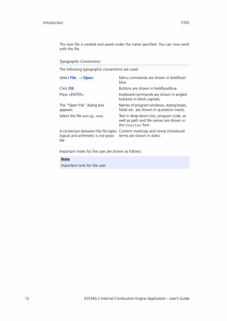
The new file is created and saved under the name specified. You can now workwith the file.
Typographic Conventions
The following typographic conventions are used:
Important notes for the user are shown as follows:
Select File → Open. Menu commands are shown in boldface/blue.
Click OK. Buttons are shown in boldface/blue.
Press <ENTER>. Keyboard commands are shown in angled brackets in block capitals.
The "Open File" dialog box appears.
Names of program windows, dialog boxes, fields etc. are shown in quotation marks.
Select the file setup.exe. Text in drop-down lists, program code, as well as path and file names are shown in the Courier font.
A conversion between the file types logical and arithmetic is not possi-ble.
Content markings and newly introduced terms are shown in italics.
Note
Important note for the user.
ES5340.2 Internal Combustion Engine Application - User’s Guide
ETAS Installation and Configuration
2 Installation and Configuration
This chapter contains information on how to install and configure the ES5340.2Internal Combustion Engine Application.
2.1 Installing the ES5340.2-ICE in the Real-Time PC
If you are setting up your real-time PC yourself or installing the PCI Express boardin an existing real-time PC at a later date, make sure you carefully follow the tipsand instructions contained in this chapter.
2.1.1 Requirements and Specifications
Released PCs and Known Installations
A list of PCs tested and released by ETAS as well as known installations(ETAS RTPC Vx.y.z HW Compatibility List.pdf) can be found in theweb interface of LABCAR-RTPC at Main Page → Documentation.
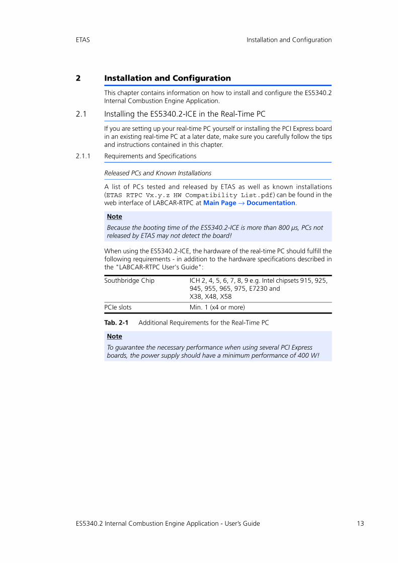
When using the ES5340.2-ICE, the hardware of the real-time PC should fulfill thefollowing requirements - in addition to the hardware specifications described inthe "LABCAR-RTPC User's Guide":
Tab. 2-1 Additional Requirements for the Real-Time PC
Note
Because the booting time of the ES5340.2-ICE is more than 800 μs, PCs not released by ETAS may not detect the board!
Southbridge Chip ICH 2, 4, 5, 6, 7, 8, 9 e.g. Intel chipsets 915, 925, 945, 955, 965, 975, E7230 and X38, X48, X58
PCIe slots Min. 1 (x4 or more)
Note
To guarantee the necessary performance when using several PCI Express boards, the power supply should have a minimum performance of 400 W!
ES5340.2 Internal Combustion Engine Application - User’s Guide 13
14
Installation and Configuration ETAS
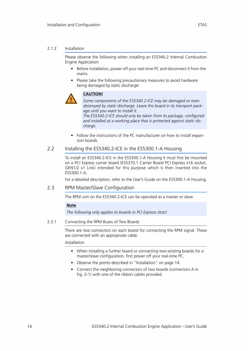
2.1.2 Installation
Please observe the following when installing an ES5340.2 Internal CombustionEngine Application:
• Before installation, power off your real-time PC and disconnect it from the mains.
• Please take the following precautionary measures to avoid hardware being damaged by static discharge:
• Follow the instructions of the PC manufacturer on how to install expan-sion boards.
2.2 Installing the ES5340.2-ICE in the ES5300.1-A Housing
To install an ES5340.2-ICE in the ES5300.1-A Housing it must first be mountedon a PCI Express carrier board (ES5370.1 Carrier Board PCI Express x16 socket,GEN1/2 x1 Link) intended for this purpose which is then inserted into theES5300.1-A.
For a detailed description, refer to the User’s Guide on the ES5300.1-A Housing.
2.3 RPM Master/Slave Configuration
The RPM unit on the ES5340.2-ICE can be operated as a master or slave.
2.3.1 Connecting the RPM Buses of Two Boards
There are two connectors on each board for connecting the RPM signal. Theseare connected with an appropriate cable.
Installation
• When installing a further board or connecting two existing boards for a master/slave configuration, first power off your real-time PC.
• Observe the points described in "Installation" on page 14.
• Connect the neighboring connectors of two boards (connectors A in Fig. 2-1) with one of the ribbon cables provided.
CAUTION!
Some components of the ES5340.2-ICE may be damaged or even destroyed by static discharge. Leave the board in its transport pack-age until you want to install it. The ES5340.2-ICE should only be taken from its package, configured and installed at a working place that is protected against static dis-charge.
Note
The following only applies to boards in PCI Express slots!
ES5340.2 Internal Combustion Engine Application - User’s Guide
ETAS Installation and Configuration
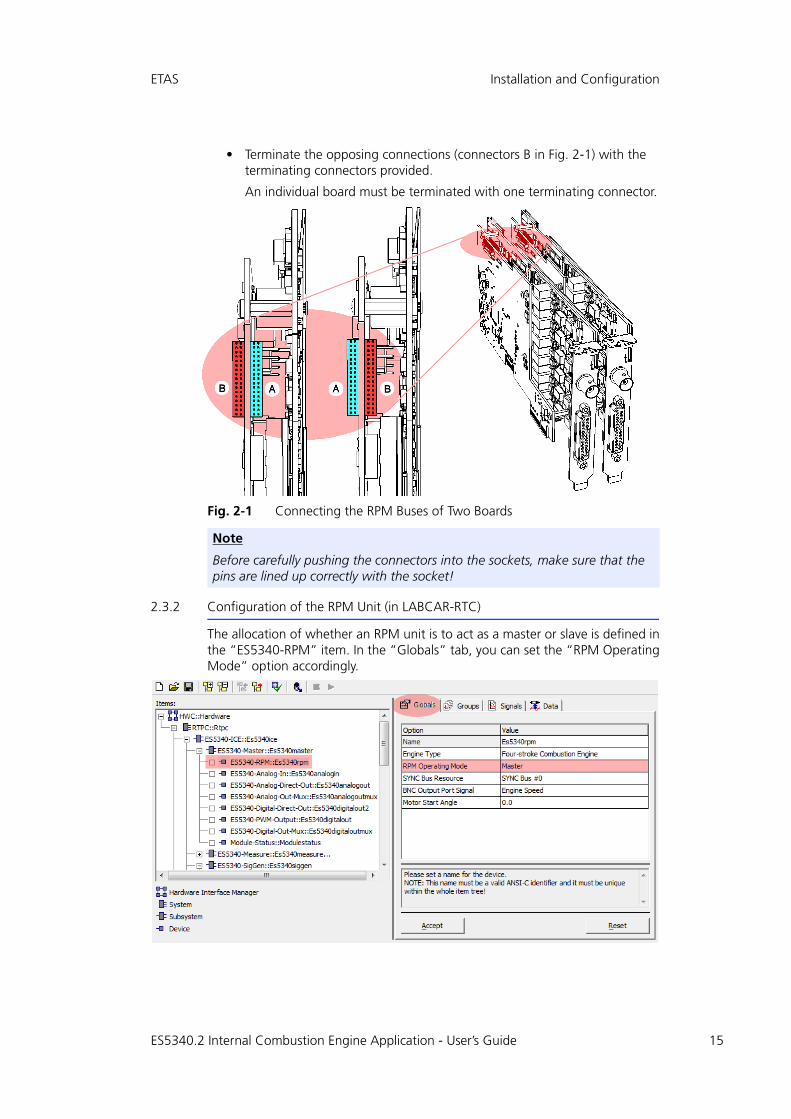
• Terminate the opposing connections (connectors B in Fig. 2-1) with the terminating connectors provided.
An individual board must be terminated with one terminating connector.
Fig. 2-1 Connecting the RPM Buses of Two Boards
2.3.2 Configuration of the RPM Unit (in LABCAR-RTC)
The allocation of whether an RPM unit is to act as a master or slave is defined inthe “ES5340-RPM” item. In the “Globals” tab, you can set the “RPM OperatingMode” option accordingly.
Note
Before carefully pushing the connectors into the sockets, make sure that the pins are lined up correctly with the socket!
ES5340.2 Internal Combustion Engine Application - User’s Guide 15

16
Installation and Configuration ETAS
ES5340.2 Internal Combustion Engine Application - User’s Guide

ETAS Hardware Description
3 Hardware Description
This chapter provides a description of the inputs and outputs of the ES5340.2Internal Combustion Engine Application along with the signals that it can mea-sure and those that can be generated for it.
Specifically, it includes information about the following topics:
• "Generating Analog Signals" on page 18
The ES5340.2 Internal Combustion Engine Application has eight analog outputs. These outputs are used for different analog signals via an output multiplexer.
– "Specification" on page 18
– "Configuring the Analog Signals" on page 19
• "Output Multiplexers for the Analog Signals" on page 20
Each analog output has a multiplexer that can be used to define the signal for this output.
• "Generating Digital Signals" on page 21
The ES5340.2 Internal Combustion Engine Application has eight digital outputs. These outputs are used for different digital signals via an output multiplexer.
– "Specification" on page 21
– "Configuring the Digital Signals" on page 21
• "Output Multiplexers for the Digital Signals" on page 22
Each digital output has a multiplexer that can be used to define the signal for this output.
• "Analog Inputs" on page 23
The ES5340.2 Internal Combustion Engine Application has four inputs for measuring analog signals.
– "Specification" on page 23
– "Configuring the Analog Inputs" on page 23
• "Digital Inputs" on page 24
The ES5340.2 Internal Combustion Engine Application has 20 inputs for measuring digital signals.
– "Specification" on page 24
– "Threshold Comparison" on page 24
– "Configuring the Digital Inputs" on page 25
– "Measurement Modes" on page 25
– "Rail Pressure Measurements" on page 26
• "Arbitrary Signal Generators" on page 28
– "RPM Generator" on page 28
– "Waveform Pool for Signal Generators" on page 28
– "Knock Signal Generator" on page 29
– "Misfire Control" on page 30
ES5340.2 Internal Combustion Engine Application - User’s Guide 17
18
Hardware Description ETAS
– "Sequence Tables" on page 30
– "MSA Sensor" on page 31
• "RPM Generator" on page 31
The ES5340.2 Internal Combustion Engine Application has a central RPM generator that outputs a speed-specific clock signal.
– "Angle Clock Signal" on page 31
– "Synchronization" on page 32
– "Configuring the RPM Unit in LABCAR-RTC" on page 33
3.1 Generating Analog Signals
The ES5340.2 Internal Combustion Engine Application has eight analog outputs.These outputs are used for different analog signals via an output multiplexer.
3.1.1 Specification
The output voltage range is -10 V to +10 V for internal reference or -12 V to+12 V for external reference voltage – the resolution of the D/A converter is16 bits.
All outputs are galvanically isolated and have an electric strength of ±60 V.In addition, each output has a cutoff relay.
The accuracy (internal reference) is ±5 mV, while the maximum current of anoutput is ±30 mA.
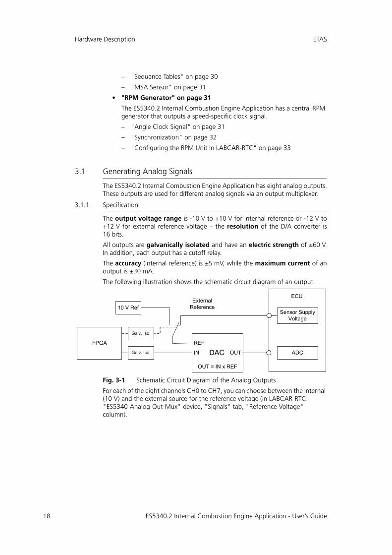
The following illustration shows the schematic circuit diagram of an output.
Fig. 3-1 Schematic Circuit Diagram of the Analog Outputs
For each of the eight channels CH0 to CH7, you can choose between the internal (10 V) and the external source for the reference voltage (in LABCAR-RTC: "ES5340-Analog-Out-Mux" device, "Signals" tab, "Reference Voltage" column).
REF
IN
OUT = IN x REF
OUT
FPGA
ExternalReference
Galv. Iso.
10 V Ref
Galv. Iso.
DAC
ECU
ADC
Sensor SupplyVoltage
ES5340.2 Internal Combustion Engine Application - User’s Guide

ETAS Hardware Description
3.1.2 Configuring the Analog Signals
Which signals are assigned to the eight outputs is defined in the output multi-plexer (see "Output Multiplexers for the Analog Signals" on page 20).
You can configure the analog channels themselves as follows.
Analog Direct Out
This can be used to output constant voltages and values calculated in the com-putation grid of a model – specified by the value of "OutValue_n" [-1.0 to +1.0]:
Uout = OutValue_n * URef
ES5340.2 Internal Combustion Engine Application - User’s Guide 19

20
Hardware Description ETAS
3.2 Output Multiplexers for the Analog Signals
Each analog output has a multiplexer that can be used to define the signal forthis output.
Sources for the Analog Outputs
The analog output channels can be driven by different sources:
• Signals from ES5340-Analog-Direct-Out
• Signals from ES5340-Analog (arbitrary signal generators)
• Signals from ES5340-Knock (knock generators)
The sources are configured in LABCAR-RTC with the "ES5340-Analog-Out-Mux"item, "Signals" tab in the "Output Select" column.
In the case of an ES5340.2 Internal Combustion Engine Application, eight signalscan be configured for the outputs here.
ES5340.2 Internal Combustion Engine Application - User’s Guide

ETAS Hardware Description
3.3 Generating Digital Signals
The ES5340.2 Internal Combustion Engine Application has eight digital outputs.These outputs are used for different digital signals via an output multiplexer.
3.3.1 Specification
The output voltage is 0 to 60 V (open collector) or 5 V (internal pull-up).
All outputs are galvanically isolated and have an electric strength of ±60 V –in addition, each output has a cutoff relay.
The maximum current of an output is ±15 mA. The rise time (0 V → 5 V) is2 μs, while the fall time (5 V → 0 V) is 2 μs.
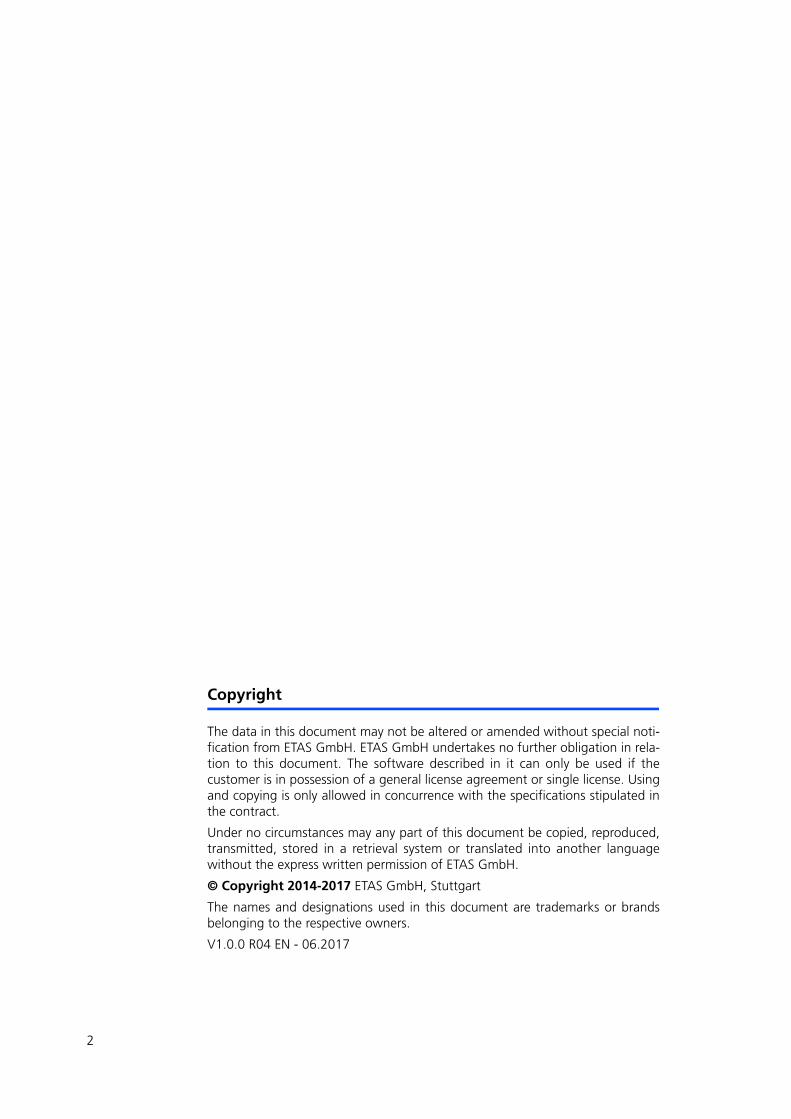
The following illustration shows the schematic circuit diagram of a digital output.
Fig. 3-2 Schematic Circuit Diagram of a Digital Output
3.3.2 Configuring the Digital Signals
Which signals are assigned to the eight outputs is defined in the output multi-plexer (see "Output Multiplexers for the Digital Signals" on page 22).
You can configure the digital channels themselves as follows.
Digital Direct Out
These outputs enable you to directly stimulate digital ECU inputs.
PWM Output
Here frequencies between 0 Hz and 100 kHz and duty cycles between 0.0 and1.0 can be selected.
FPGA
Galv. Iso.
ECU5 V Supply
Out 1
CommonGND
Galv. Iso.
+
-
ES5340.2 Internal Combustion Engine Application - User’s Guide 21

22
Hardware Description ETAS
3.4 Output Multiplexers for the Digital Signals
Each digital output has a multiplexer that can be used to define the signal for thisoutput.
Sources for the Digital Outputs
The digital output channels can be driven by different sources:
• Output values of all Digital-Out RTIO elements (ES5340-Digital-Direct-Out and ES5340-PWM-Output)
• Digital signals of the arbitrary signal generators (ES5340-SigGen)
• MSA Sensor signal
The sources are configured in LABCAR-RTC with the "ES5340-Digital-Out-Mux"item, "Signals" tab in the "Output Select" column.
The output mode can be set to "Open Collector" or "Pull-Up to +5V".
ES5340.2 Internal Combustion Engine Application - User’s Guide

ETAS Hardware Description
3.5 Analog Inputs
The ES5340.2 Internal Combustion Engine Application has four inputs for mea-suring analog signals.
3.5.1 Specification
The input voltage range for two inputs is 0 to 5 V, with two additional inputs,it is 0 V to +40 V. All inputs are galvanically isolated and have an electricstrength of ±60 V – the impedance of the inputs is 1 MΩ.
The sampling rate is 500 kSamples/s (software averaging is possible using 2n
(n =1 to 8) samples) at a resolution of 12 bits.
3.5.2 Configuring the Analog Inputs
The analog inputs can be used to measure battery voltages and other constantvoltages (control signals).
The type of averaging used for the detected signals can be configured in LAB-CAR-RTC in the "ES5340-Analog-In" item of the "Signals" tab.
ES5340.2 Internal Combustion Engine Application - User’s Guide 23

24
Hardware Description ETAS
3.6 Digital Inputs
The ES5340.2 Internal Combustion Engine Application has 20 inputs for measur-ing digital signals.
3.6.1 Specification
The input voltage range is 0 to +60 V. All inputs are galvanically isolated andhave an electric strength of ±60 V.
The maximum input frequency is 125 kHz, and the resolution is 8 ns(125 MHz).
Each input has two independently programmable thresholds for determiningthe status of the input ("High" or "Low"). The setting range for these thresholdvalues is 0 V to +10 V.
The following illustration shows the schematic circuit diagram of a digital input.
Fig. 3-3 Schematic Circuit Diagram of a Digital Input
3.6.2 Threshold Comparison
Each of the 20 input signals of the ES5340.2-ICE is compared to two thresholdvalues in the FPGA. This comparison leads to a conversion of the analog inputsignal to digital 0/1 information.
The thresholds can be configured by software – the following three possibilitiesare available:
• Comparison to 1/3 UBatt_X and 2/3 UBatt_X (X = A...E)
• Comparison to the four analog inputs AnaIn_0...3
• Comparison to any two thresholds which can be configured by software (RTIO).
DACLowECU
GND
InCh0Galv. Iso.
DACHigh
Galv. Iso.High LevelDetection
Low LevelDetection
FPGA
ES5340.2 Internal Combustion Engine Application - User’s Guide
ETAS Hardware Description
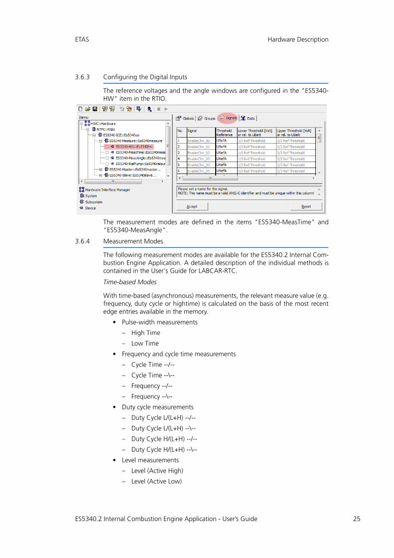
3.6.3 Configuring the Digital Inputs
The reference voltages and the angle windows are configured in the "ES5340-HW" item in the RTIO.
The measurement modes are defined in the items "ES5340-MeasTime" and"ES5340-MeasAngle".
3.6.4 Measurement Modes
The following measurement modes are available for the ES5340.2 Internal Com-bustion Engine Application. A detailed description of the individual methods iscontained in the User's Guide for LABCAR-RTC.
Time-based Modes
With time-based (asynchronous) measurements, the relevant measure value (e.g.frequency, duty cycle or hightime) is calculated on the basis of the most recentedge entries available in the memory.
• Pulse-width measurements
– High Time
– Low Time
• Frequency and cycle time measurements
– Cycle Time --/--
– Cycle Time --\--
– Frequency --/--
– Frequency --\--
• Duty cycle measurements
– Duty Cycle L/(L+H) --/--
– Duty Cycle L/(L+H) --\--
– Duty Cycle H/(L+H) --/--
– Duty Cycle H/(L+H) --\--
• Level measurements
– Level (Active High)
– Level (Active Low)
ES5340.2 Internal Combustion Engine Application - User’s Guide 25
26
Hardware Description ETAS
Angle-synchronous Modes
Angle windows which are specified by a lower angle window limit (LWL) in CA°and an upper angle window limit (UWL) in °CA are characteristic for angle-syn-chronous measurements.
The user can define up to three angle windows per hardware channel which canoverlap but whose size must not exceed 720 °CA (360 °CA with two-strokeengine).
• Additive pulse-width measurements
– Additive Hightime
– Additive Lowtime
• Measuring edges: angle stamp
– Rising Edge of n-th Pulse
– Falling Edge of n-th Pulse
• Measuring width of n-th pulse
– H-Time n-th Pulse (H-Valid.)
– H-Time n-th Pulse (L-Valid.)
– H-Time n-th Pulse (Pu Qual.)
– L-Time n-th Pulse (Pu Qual.)
• Measuring edges: time stamp
– Time Stamp of n-th Rising Edge
– Time Stamp of n-th Falling Edge
• Pulse count
– Number of Low-Pulses
– Number of High-Pulses
3.6.5 Rail Pressure Measurements
The ES5340.2 Internal Combustion Engine Application provides the "ES5340-RailPump" item with the following speed-synchronous measurement modes formeasuring rail pressure:
• Angle of first rising edge of a pulse sequence
• Angle of first falling edge of a pulse sequence
• Angle of last rising edge of a pulse sequence
• Angle of last falling edge of a pulse sequence
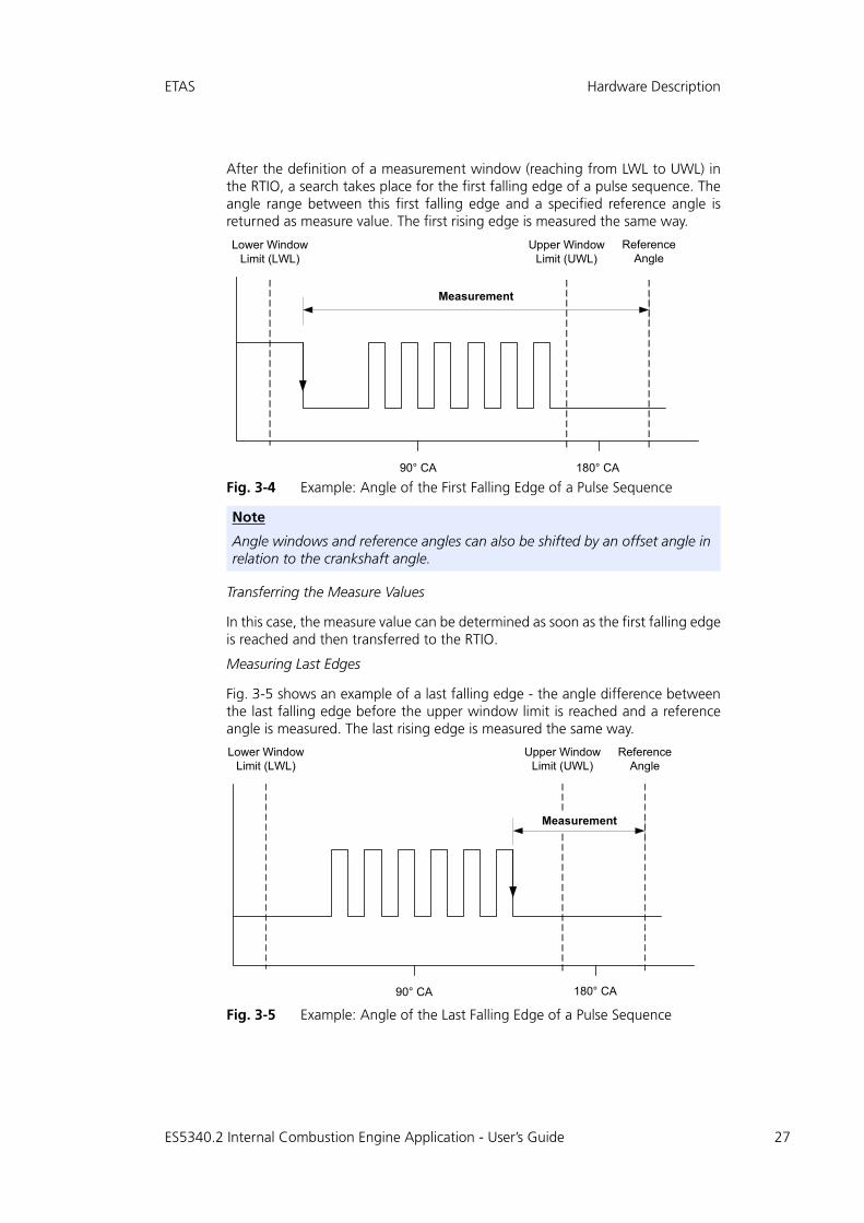
Measuring First Edges
The measurement mode for the first falling (or rising) edge works as follows (seethe example of a first falling edge in Fig. 3-4 on page 27):
ES5340.2 Internal Combustion Engine Application - User’s Guide
ETAS Hardware Description
After the definition of a measurement window (reaching from LWL to UWL) inthe RTIO, a search takes place for the first falling edge of a pulse sequence. Theangle range between this first falling edge and a specified reference angle isreturned as measure value. The first rising edge is measured the same way.
Fig. 3-4 Example: Angle of the First Falling Edge of a Pulse Sequence
Transferring the Measure Values
In this case, the measure value can be determined as soon as the first falling edgeis reached and then transferred to the RTIO.
Measuring Last Edges
Fig. 3-5 shows an example of a last falling edge - the angle difference betweenthe last falling edge before the upper window limit is reached and a referenceangle is measured. The last rising edge is measured the same way.
Fig. 3-5 Example: Angle of the Last Falling Edge of a Pulse Sequence
Note
Angle windows and reference angles can also be shifted by an offset angle in relation to the crankshaft angle.
90° CA 180° CA
ReferenceAngle
Measurement
Lower Window Limit (LWL)
Upper Window Limit (UWL)
90° CA 180° CA
ReferenceAngle
Lower Window Limit (LWL)
Upper Window Limit (UWL)
Measurement
ES5340.2 Internal Combustion Engine Application - User’s Guide 27
28
Hardware Description ETAS
Transferring the Measure Values
The determination and subsequent transfer of the measure values is as follows:The angle of the falling edge currently detected is always stored in a register ofthe ES5340.2-ICE – as soon as a new falling edge is detected, the register isoverwritten with the new angle value.
Once the upper window limit is reached, the angle value last stored is read fromthe register, the difference to the reference angle (= the measure value) is calcu-lated and then transferred to the RTIO.
3.7 Arbitrary Signal Generators
There are eight analog and eight digital signal generators available on theES5340.2-ICE. Each of the signal generators can play back one of the 16 wave-forms. A central RPM generator and one variable clock generator per signal gen-erator (maximum frequency: 1 MHz) are available as clock sources.
One individual basic phase as well as an additional phase shift can be selectedper signal generator. The speed at which a change of the phase shift takes effectcan be defined.
When using the variable clock generator, the frequency of the clock generator,the trigger mode (single shot, continuous) and a trigger signal can be specified.
The amplitude of the internal output signal of the signal generator can be variedbetween 0.0 and 1.0.
3.7.1 RPM Generator
The ES5340.2-ICE has a central speed generator (RPM generator) which outputsan engine-speed-specific clock signal. This clock signal can be used by the signalgenerators to read out and output the waveforms. The maximum speed is60000 rpm, the resolution in around 0.1 rpm. The speed signal itself can bemodulated using a misfire generator.
For measuring purposes, the speed signal can be applied to the "SYNC" port (onthe front panel) of the ES5340.2-ICE (see "Sync Port" on page 240).
Angular Resolution
The angular resolution is 65536 points per cycle. With a typical four-strokeengine with a period of 720 °CA, this corresponds to an angular resolution ofaround 0.01 °CA.
3.7.2 Waveform Pool for Signal Generators
There are 16 waveforms available which can be used by the arbitrary signal gen-erators. The user can describe the waveforms with tables. The signal trace in thetable is written to the relevant waveform using an interpolation procedure.
Waveform resolution.
The maximum resolution of a waveform is determined by the maximum possiblenumber of 65536 data points. Here too, the resolution can be reduced to 16points in powers of two; please note that the resolution (1/(number of datapoints)) of a waveform must be smaller than or equal to the angular resolution.Normally the resolution of a waveform should correspond to the angular resolu-tion.
ES5340.2 Internal Combustion Engine Application - User’s Guide

ETAS Hardware Description
The waveforms are read out and output by the signal generators. Either the cen-tral RPM generator can act as clock source or a variable frequency generator(maximum frequency: 1 MHz) in the signal generator is used.
Waveform resolution smaller than angular resolution.
If a high-frequency signal is to be output via the signal generator (using the vari-able frequency generator), it might be necessary to keep the resolution of onewaveform smaller than the angular resolution.
The following example illustrates the procedure:
If a sinusoidal signal of 40 kHz is to be output, the signal table describes a singlesine period. The angular resolution is 65536 points. Due to a maximum fre-quency of the variable clock generator of 1 MHz, the maximum signal frequencyfor the sinusoidal signal is 1 MHz/65536 = 15.25 Hz which, of course, is consid-erably less than the desired 40 kHz. By reducing the waveform resolution to, forexample, 16 data points, the sinusoidal signal is stored several times in succes-sion (in fact 65536/16 = 4096-fold) in the waveform with 65536 data points.This results in a total maximum frequency for the sinusoidal signal of 1 MHz/16= 62.5 kHz, which is above the desired frequency of 40 kHz. Due to a corre-sponding reduction of the variable clock frequency (f=1/rate) to 640 kHz, thedesired sinusoidal signal can be generated with 40 kHz.
The example shows that due to a reduction in the waveform resolution in com-parison to the angular resolution, the waveform resolution is not really reduced.The signal of the signal table is simply written to the waveform several times insuccession and the "visible" resolution thus reduced.
3.7.3 Knock Signal Generator
The knocking which occurs with a combustion engine can be simulated by theknock signal generator. A knock signal consists of individual knock packages. Aknock package itself consists of a sinusoidal oscillation with selectable frequencyand an envelope curve which modulates the sinusoidal oscillation with a durationwhich can be defined.
The following figure shows an individual knock package. A sine half wave is usedas an envelope curve.
Fig. 3-6 A Knock Package
Non-knocking combustion also generates noises which are acquired by a realstructure-borne noise knock sensor. A distinction is made between correct andknocking combustion via the control of the amplitude of the knock signal.
Envelope Duration
ES5340.2 Internal Combustion Engine Application - User’s Guide 29

30
Hardware Description ETAS
In addition, there is also a stochastic variation of the amplitude of a knock pack-age. This is used for the simulation of variations in the knock signals which occurin real operation.
A certain amount of noise also exists if no knock package is being output. Thisbasic noise is required for example to be able to get through the initial diagnos-tics of the sensor. Modern ECUs treat inputs without noise as faulty or not pres-ent.
The angular position (in °CA) of a knock signal as well as the occurrence of theknock event can now be controlled individually for each cylinder using a proba-bility value or sequence tables (see "Sequence Tables" on page 30).
The knock signal generator has four internal outputs. You can select which cylin-ders serve the relevant output. In multi-cylinder vehicles, it is important that indi-vidual knock packages can overlay each other.
3.7.4 Misfire Control
A control mechanism is available on the ES5340.2-ICE to simulate misfiring; thisresults in a modulation of the speed of the RPM generator in a specific anglerange. It is possible to modify the speed in relation to the specified speed of theRPM generator (reduce/increase by the factor 0.01 to 2.0). When simulating mis-firing, the speed is normally reduced in comparison to the defined speed.
The start effect angle of speed modulation can be defined for each individualcylinder. The effect of speed modulation can be controlled for each cylinder usinga probability value or sequence tables (see "Sequence Tables" on page 30).
Speed modulation can be defined via four modulation profiles which representthe course of modulation over a complete period of 720 °CA (or 360 ° for two-stroke engines). A value of 1.0 represents a non-existent modulation; 0.01reduces the speed to 1% of the specified speed; 2.0 doubles the specified speed.One of the four available modulation profiles can be selected individually percylinder.
3.7.5 Sequence Tables
Sequence tables are used with the misfire generator and the knock signal gener-ator. They make it possible for the user to describe complex knock and misfiringsequences.
A table with a maximum of 100 data points is used for this purpose. Once thesequence has been started, the sequence proceeds one data point per period. Inthe case of misfiring, a value greater than 0.5 at the relevant data point meansthat misfiring occurs in this period. With the knock signal generator, this value inthe table can also be used to define the intensity with which the knock sensorperceives the knock signal (close cylinder: high value, distant cylinder: low value).
After 100 data points, the sequence is either started from the beginning again("Sequence trigger = continuous"), or play-back is terminated ("Sequence trig-ger = Single Shot") and has to be restarted via the relevant trigger signal.
Note
A maximum of four waveforms can overlay each other!
ES5340.2 Internal Combustion Engine Application - User’s Guide

ETAS Hardware Description
It is possible to specify one individual sequence per cylinder. There is, however,one common sequence ("Common Sequence") both with the misfire generatorand the knock generator which all cylinders can access. This facilitates the fastsetting of sequences which are to be used for several cylinders.
3.7.6 MSA Sensor
Signal generators are also used to simulate crankshaft sensors which can detectthe direction of rotation (MSA sensors). A tooth pulse has no fixed angle widthbut a fixed pulse duration. Moreover, the output signal is predefined as being alow-active open collector signal.
If an MSA sensor RTIO element is used, (potential) tooth center information iscalculated for all waveform traces during configuration and stored in the wave-form pool. However, not all waveforms are necessarily suitable for this algorithm;when an unsuitable waveform is selected, an error message is issued.
3.8 RPM Generator
The ES5340.2 Internal Combustion Engine Application has a central RPM gener-ator that outputs a speed-specific clock signal.
This RPM unit generates a 16-bit angle value that, in turn, is used for generatingarbitrary signals using analog or digital signal generators.
The maximum speed is:
• 60000 rpm (for 720° crankshaft angle of a four-stroke engine)
• 30000 rpm (for 360° crankshaft angle of a two-stroke engine)
The angle resolution is 0.011 °CA (16 bit).
3.8.1 Angle Clock Signal
The angle clock signal consists of three signals (see Fig. 3-7 on page 32):
• The synchronization signal at 0 °CA
• The actual clock signal
• The signal for the direction of rotation (DOR)
A "High" level of the DOR signal means "rotation with increasing crank-shaft angle," while a "Low" level means "rotation with decreasing crank-shaft angle".
One of these three clock signals can be output via a multiplexer to the BNC con-nection on the front panel (see "Connector for the Angle Clock Signal"on page 39).
In addition, the engine speed can be output to this connection. This signal is"High" (= 5 V) if the current crankshaft angle is between 0° and 360° (or 0° and180°) and "Low" (= 0 V) for crankshaft angles between 360° and 720° (or 0°and 360°).
ES5340.2 Internal Combustion Engine Application - User’s Guide 31

32
Hardware Description ETAS
The following illustration shows the course of the four signals over one camshaftrevolution.
Fig. 3-7 Sync, Clock, Direction and Engine Speed Signals
3.8.2 Synchronization
An angle- or speed-based synchronization of multiple ES5340.2-ICE is possible.For this purpose, any ES5340.2-ICE is configured as the "RPM master", all othersas "RPM slave".
V
Low
High
Sync
V
Low
High
V
Low
High
Clock
Direction
V
Low
High
Engine Speed
0 °CA 720 °CA
0 °CA 360 °CA
360 °CA
180 °CA
αFour-Stroke Engine
αTwo-Stroke Engine
ES5340.2 Internal Combustion Engine Application - User’s Guide

ETAS Hardware Description
3.8.3 Configuring the RPM Unit in LABCAR-RTC
To define the operating mode of the RPM unit, select the item "ES5340-RPM" inLABCAR-RTC and select the "RPM Operating Mode" option in the "Globals"tab.
The following settings are possible for the "RPM Operating Mode" option:
• Slave
The ES5340.2-ICE is synchronized to an external angle clock signal.
• Master
The angle clock signal is generated – based on the mechanical angular velocity – on the ES5340.2-ICE.
ES5340.2 Internal Combustion Engine Application - User’s Guide 33

34
Hardware Description ETAS
ES5340.2 Internal Combustion Engine Application - User’s Guide

ETAS Connector Assignment and Display Elements
4 Connector Assignment and Display Elements
This chapter contains the description of the connectors and display elements ofthe ES5340.2 Internal Combustion Engine Application.
It consists of the following sections:
• "Connector Assignment" on page 36
This section describes all connectors on the front panel.
– "Connector for the Outputs" on page 36
– "Connector for the Inputs" on page 37
– "Connector for the Angle Clock Signal" on page 39
• "Display Elements" on page 39
This section describes the meaning of the LED display on the front panel.
ES5340.2 Internal Combustion Engine Application - User’s Guide 35

36
Connector Assignment and Display Elements ETAS
4.1 Connector Assignment
This section describes the assignment of the connectors of the inputs and out-puts of the ES5340.2-ICE.
4.1.1 Connector for the Outputs
The connector is a DSUB25 connector (female). The shielding is to the front paneland housing potential and thus to protective earth.
Fig. 4-1 Connector for the Outputs (Top View)
Tab. 4-1 Assignment of the Connector for the Outputs
Pin Signal Pin Signal
1 Analog Output Channel 0 14 Ground Channel 0
2 External Ref. Channel 0 15 Digital Output Channel 0
3 Analog Output Channel 1 16 Ground Channel 1
4 External Ref. Channel 1 17 Digital Output Channel 1
5 Analog Output Channel 2 18 Ground Channel 2
6 External Ref. Channel 2 19 Digital Output Channel 2
7 Analog Output Channel 3 20 Ground Channel 3
8 External Ref. Channel 3 21 Digital Output Channel 3
9 Analog Output Channel 4 22 Ground Channel 4
10 External Ref. Channel 4 23 Digital Output Channel 4
11 Analog Output Channel 5 24 Ground Channel 5
12 External Ref. Channel 5 25 Digital Output Channel 5
13 n.c. Housing to protective earth
Note
Analog and digital ground of an output channel are identical!
13 25
141
ES5340.2 Internal Combustion Engine Application - User’s Guide

ETAS Connector Assignment and Display Elements
4.1.2 Connector for the Inputs
The connector is a DSUB62HD connector (male). The shielding is to protectiveearth.
Fig. 4-2 Connector for the Inputs (Top View)
43
2142
62
1
22
ES5340.2 Internal Combustion Engine Application - User’s Guide 37

38
Connector Assignment and Display Elements ETAS
Tab. 4-2 Assignment of the Connector for the Inputs
Pin Signal Pin Signal Pin Signal
1 Analog Output Channel 6 –
22 Analog Output Channel 6 +
43 Analog Output Channel 6 AGND
2 Digital Output Channel 6
23 Excitation + 44 Digital Output Channel 6 AGND
3 Analog Output Channel 7 –
24 Analog Output Channel 7 +
45 Analog Output Channel 7 AGND
4 Digital Output Channel 7
25 Excitation – 46 Digital Output Channel 7 AGND
5 Digital Input Channel 0
26 Digital Input Channel 13
47 Digital Input Ground
6 Digital Input Channel 1
27 Digital Input Channel 14
48 Digital Input Ground
7 Digital Input Channel 2
28 Digital Input Channel 15
49 Digital Input Ground
8 Digital Input Channel 3
29 Digital Input Channel 16
50 Digital Input Ground
9 Digital Input Channel 4
30 Digital Input Channel 17
51 Digital Input Ground
10 Digital Input Channel 5
31 Digital Input Channel 18
52 Digital Input Ground
11 Digital Input Channel 6
32 Digital Input Channel 19
53 Digital Input Ground
12 Digital Input Channel 7
33 Digital Input Ground 54 Digital Input Ground
13 Digital Input Channel 8
34 Digital Input Ground 55 Digital Input Ground
14 Digital Input Channel 9
35 Digital Input Ground 56 Digital Input Ground
15 Digital Input Channel 10
36 Digital Input Ground 57 Digital Input Ground
16 Digital Input Channel 11
37 Digital Input Ground 58 Digital Input Ground
17 Digital Input Channel 12
38 Digital Input Ground 59 Digital Input Ground
18 Digital Input Ground 39 Analog Input Ground
60 Analog Input Ground
19 Analog Input Channel 0
40 Analog Input Channel 2
61 Analog Input Ground
20 Analog Input Channel 1
41 Analog Input Channel 3
62 Analog Input Ground
21 Analog Input Ground
42 Analog Input Ground
Housing to protective earth
ES5340.2 Internal Combustion Engine Application - User’s Guide

ETAS Connector Assignment and Display Elements
4.1.3 Connector for the Angle Clock Signal
The connector for the angle clock signal is a BNC connector (female).
Fig. 4-3 Connector for the Angle Clock Signal
Tab. 4-3 Assignment of the Connector for the Angle Clock Signal
4.2 Display Elements
The front panel of the ES5340.2 Internal Combustion Engine Application has anLED for identifying the board from the web interface of LABCAR-RTC.
Pin Signal
1 "Sync", "Clock", "Direction" or "Engine Speed" (see hardware configuration in LABCAR-RTC: ES5340-RPM Item, "Globals" tab, "BNC Output Port Signal" option)
1
ES5340.2 Internal Combustion Engine Application - User’s Guide 39

40
Connector Assignment and Display Elements ETAS
ES5340.2 Internal Combustion Engine Application - User’s Guide

ETAS Technical Data and Standards
5 Technical Data and Standards
This chapter contains the technical data on the ES5340.2 Internal CombustionEngine Application.
Analog Outputs
Digital Outputs
Number 8
Output voltage range -10 V to +10 V (internal reference)-12 V to +12 V (external reference)
Accuracy without load ±5 mV (+23 °C/+73 °F)
Accuracy with load (12 kΩ) ±10 mV (+23 °C/+73 °F)
Output current ±30 mA (typical)
Resolution 16 bit
Overvoltage protection ±60 V
Galvanic isolation Yes
Number 8
Output voltage range Open collector: 0 to 60 VInternal pull-up: 5 V
Output current Max. ±15 mA
Frequency range 1 Hz...100 kHz
Accuracy between 1 Hz and 10 kHz ±0.04%
Accuracy between 10 kHz and 100 kHz ±0.4%
Rise time (0 V → 5 V) 2 μs (typical)
Fall time (5 V → 0 V) 2 μs (typical)
Duty cycle 0%...100%
Accuracy of duty cycle (50%) between 1 Hz and 10 kHz
±0.2%...±2% (linear)
Accuracy of duty cycle (50%) between 10 kHz and 100 kHz
±2%...±20% (linear)
Clock rate for PWM generation 8 ns
Overvoltage protection ±60 V
Galvanic isolation Yes
ES5340.2 Internal Combustion Engine Application - User’s Guide 41

42
Technical Data and Standards ETAS
Analog Inputs
Digital Inputs
RPM Clock Module
Number 4
Input voltage range 0...+5 V (CH0, CH2)0 V to 40 V (CH1, CH3)
Resolution 12 bit
Impedance 1 MΩ
Sampling rate 500 kSamples/s
Overvoltage protection ±60 V
Galvanic isolation Yes
Number 20
Input voltage range 0 to +60 V
Frequency range 1 Hz...100 kHz
Duty cycle 0%...100%
Resolution of duty cycle 0.1%
Accuracy between 1 Hz and 10 kHz ±0.04%
Accuracy between 10 kHz and 100 kHz ±0.4%
Resolution 8 ns (125 MHz)
Programmable thresholds for high/low detection of input signal
Adjustable: 0 V to +10 V
Overvoltage protection ±60 V
Galvanic isolation Yes
Angular resolution 0.011 °CA
Max. engine speed 60000 rpm
ES5340.2 Internal Combustion Engine Application - User’s Guide

ETAS Technical Data and Standards
Data Acquisition
Electrical Data
Environmental Conditions
5.1 Fulfilled Standards and Norms
The ES5340.2 Internal Combustion Engine Application complies with the follow-ing standards and norms:
Max. number of pulses per channel and 720° CA
32
Minimum pulse width 100 ns
Duty cycle 0 ... 100%
Rise and fall time measurement 800 ns … 300 μs
Frequency range 0.1 Hz ... 20 kHz
Accuracy of frequency measurement ± (160 ns + 0.1%)
Accuracy of high-time ± (0.5 μs + 0.5%)
Current consumption 980 mA @ +3.3 V DC 780 mA @ +12 V DC
Operating temperature +5 °C to +35 °C (+41 °F to +95 °F)
Relative humidity 0 to 95% (non-condensing)
Norm Test
IEC 61326-1 Electrical equipment for measurement, control and laboratory use – EMC requirements
IEC 61010-1 Safety requirements for electrical equipment for measure-ment, control and laboratory use - Part 1: General require-ments
IEC 61000-6-2 Immunity (industrial environments)
IEC 61000-6-3 Emission standard (residential, commercial andlight-industrial environments)
Note
The signal lines may not exceed a length of 3 m!
ES5340.2 Internal Combustion Engine Application - User’s Guide 43

44
Technical Data and Standards ETAS
ES5340.2 Internal Combustion Engine Application - User’s Guide
ETAS ETAS Contact Addresses
6 ETAS Contact Addresses
ETAS HQ
ETAS GmbH
ETAS Subsidiaries and Technical Support
For details of your local sales office as well as your local technical support teamand product hotlines, take a look at the ETAS website:
Borsigstraße 14 Phone: +49 711 3423-0
70469 Stuttgart Fax: +49 711 3423-2106
Germany WWW: www.etas.com
ETAS subsidiaries WWW: www.etas.com/en/contact.php
ETAS technical support WWW: www.etas.com/en/hotlines.php
ES5340.2 Internal Combustion Engine Application - User’s Guide 45

46
ETAS Contact Addresses ETAS
ES5340.2 Internal Combustion Engine Application - User’s Guide

ETAS Figures
Figures
Fig. 1-1 Front Panel of the ES5340.2 Internal Combustion Engine Application ........... 6Fig. 1-2 WEEE Symbol ............................................................................................. 10Fig. 2-1 Connecting the RPM Buses of Two Boards .................................................. 15Fig. 3-1 Schematic Circuit Diagram of the Analog Outputs ...................................... 18Fig. 3-2 Schematic Circuit Diagram of a Digital Output ............................................ 21Fig. 3-3 Schematic Circuit Diagram of a Digital Input ............................................... 24Fig. 3-4 Example: Angle of the First Falling Edge of a Pulse Sequence ...................... 27Fig. 3-5 Example: Angle of the Last Falling Edge of a Pulse Sequence ...................... 27Fig. 3-6 A Knock Package........................................................................................ 29Fig. 3-7 Sync, Clock, Direction and Engine Speed Signals......................................... 32Fig. 4-1 Connector for the Outputs (Top View) ........................................................ 36Fig. 4-2 Connector for the Inputs (Top View) ........................................................... 37Fig. 4-3 Connector for the Angle Clock Signal ......................................................... 39ES5340.2 Internal Combustion Engine Application - User’s Guide 47

48
Figures ETAS
ES5340.2 Internal Combustion Engine Application - User’s Guide

ETAS Index
Index
AAccident prevention 8Analog Direct Out 19Analog inputs 23configuration 23specification 23
Analog signals 18analog direct out 19configuration 19specification 18
Angle clock signal 31
CCE Declaration of Conformity 9Connecting devices 7Connector
angle clock signal 39input signals 37output signals 36
Connectors 35
DDevices
connecting 7Digital Direct Out 21Digital inputs 24
specification 24
Digital signals 21configuration 21digital direct out 21specification 21
Documentation 7
EElectrical safety 8ETAS Contact Addresses 45
HHardware requirements 13HW Compatibility List 13
IIdentifications on the product 9Incorrect use 8Installation 14
MMeasurement modes 25
OOccupational health and safety 8Output multiplexer
sources 20, 22
PProduct Back 10Product non-liability 7
ES5340.2 Internal Combustion Engine Application - User’s Guide 49

50
Index ETAS
QQualification, required 8
RRecycling 10RoHS conformity
China 9European Union 9
RPM signal 31
SSafety instructions 7Safety instructions, labeling 7Signal generators
arbitrary 28Standards and norms 43
TThreshold comparison 24
WWaste Electrical and Electronic Equip-
ment 10WEEE take-back system 10
ES5340.2 Internal Combustion Engine Application - User’s Guide