Embed Size (px)
Citation preview

ww
w.esa.int
European Space Agency | Bulletin 137 | February 2009
An ESA Communications ProductionCopyright 2009 © European Space Agency
bulletin→ space for europe
number 137 | February 2009
ESA Member States
Austria
Belgium
Czech Republic
Denmark
Finland
France
Germany
Greece
Ireland
Italy
Luxembourg
Netherlands
Norway
Portugal
Spain
Sweden
Switzerland
United Kingdom

←
On cover: Is climate change accelerating the water cycle? Due to be launched this year, ESA’s SMOS satellite will observe soil moisture over Earth’s landmasses and salinity of the ocean surface. These data are vital for hydrological studies and for improving our understanding of ocean circulation patterns.
The ESA headquarters are in Paris.
The major establishments of ESA are:
ESTEC, Noordwijk, Netherlands.
ESOC, Darmstadt, Germany.
ESRIN, Frascati, Italy.
ESAC, Madrid, Spain.
Chairman of the Council: M. Lucena
Director General: J.-J. Dordain→
→→
→
The European Space Agency was formed out of, and took over the rights and obligations of, the two earlier European space organisations – the European Space Research Organisation (ESRO) and the European Launcher Development Organisation (ELDO). The Member States are Austria, Belgium, Czech Republic, Denmark, Finland, France, Germany, Greece, Ireland, Italy, Luxembourg, the Netherlands, Norway, Portugal, Spain, Sweden, Switzerland and the United Kingdom. Canada is a Cooperating State.
In the words of its Convention: the purpose of the Agency shall be to provide for and to promote, for exclusively peaceful purposes, cooperation among European States in space research and technology and their space applications, with a view to their being used for scientific purposes and for operational space applications systems:
by elaborating and implementing a long-term European space policy, by recommending space objectives to the Member States, and by concerting the policies of the Member States with respect to other national and international organisations and institutions;by elaborating and implementing activities and programmes in the space field;by coordinating the European space programme and national programmes, and by integrating the latter progressively and as completely as possible into the European space programme, in particular as regards the development of applications satellites;by elaborating and implementing the industrial policy appropriate to its programme and by recommending a coherent industrial policy to the Member States.
The Agency is directed by a Council composed of representatives of the Member States. The Director General is the chief executive of the Agency and its legal representative.
European Space Agency

THE PROGRAMMATIC AND TECHNICAL CHALLENGES OF SMOSA foreword Volker Liebig → 02
EXPLORING THE WATER CYCLE OF THE BLUE PLANET The Soil Moisture and Ocean Salinity (SMOS) mission Mark Drinkwater et al → 06
STAR IN THE SKYThe SMOS payload: MIRAS Manuel Martín-Neira et al → 16
GETTING DOWN TO BUSINESSSMOS operations and products Susanne Mecklenburg et al → 24
LEAP AHEAD IN SPACE COMMUNICATIONSQuantum technologies for space systems Josep Perdigues-Armengol et al → 32
A TOUCHSTONE FOR SUCCESSCore technology activity for future launchers Guy Ramusat → 40
ESA’S ‘BILLION-PIXEL’ CAMERAThe challenges of the Gaia mission Giuseppe Sarri et al → 50
ESA’S ROOM WITH A VIEWNode-3 and Cupola ready for launch Philippe Deloo & Sara Pastor → 60
THE FIRST EUROPEAN ASTEROID ‘FLYBY’Rosetta operations for the flyby of asteroid 2867 Steins Sylvain Lodiot et al → 68
NEWS - IN BRIEF → 76
PROGRAMMES IN PROGRESS → 86
PUBLICATIONS → 114
number 137 | February 2009 40
32
06
The ESA Bulletin is an ESA Communications production.
Published by:ESA Communication & Knowledge Department
Communication Production OfficeESTEC, PO Box 2992200 AG NoordwijkThe NetherlandsTel: +31 71 565 3408
Email: [email protected]
EditorCarl Walker
DesignerRoberta Sandri
Organisationwww.esa.int/credits
Copyright © 2009 European Space AgencyISSN 0376-4265 | e-ISSN 1608-4713
The ESA Bulletin is published by the European Space Agency. Individual articles may be reprinted provided the credit line reads ‘Reprinted from ESA Bulletin’, plus date of issue. Reprinted signed articles must bear the authors’ names. Advertisements are accepted in good faith; ESA accepts no responsibility for their content claims.
Images copyright ESA unless stated otherwise. Permission to reproduce or distribute material identified as copyright of a third party must be obtained from the copyright owner concerned.
→ contents


A foreword by Volker Liebig
→ ThE ProgrAmmATic And TEchnicAL chALLEngES of SmoS

www.esa.int4
eart
h ob
serv
atio
n
ESA’s fleet of Earth Explorers are research missions focusing on the different characteristics of our planet. They will make global observations from space to advance our understanding of the interactions within the Earth system and investigate the impact of human activities on our environment.
The SMOS mission will provide data on two key variables in the hydrological (water) cycle: soil moisture and ocean salinity. Both are important in climate research to improve climate change predictions.
SMOS observations of soil moisture will further our knowledge about processes in the water and energy fluxes at the land surface/atmosphere interface and will provide information on storage of water, water uptake by
vegetation, fluxes at the interface and the effect of these on water run-off.
This knowledge is important to improve meteorological and hydrological modelling and forecasting, water resource management and monitoring of plant growth, and contributes to the forecasting of hazardous events such as floods.
Ocean salinity is a key variable in characterising global ocean circulation and its seasonal and interannual variability, and thus is an important constraint in ocean-atmosphere models. SMOS observations will therefore improve seasonal-to-interannual climate predictions (e.g. for the El Niño Southern Oscillation), and the estimates of ocean rainfall and thus the global hydrologic budgets.
They will also aid the monitoring of large-scale salinity events and improve monitoring of sea-surface salinity variability. The latter is needed to better understand and characterise the distribution of bio-geochemical parameters in the ocean’s surface and upper layers.
Providing such data from space represents a real technical feat. The instrument on SMOS, the Microwave Imaging Radiometer using Aperture Synthesis (MIRAS), operates in the microwave ‘L band’ frequency range at 1.4 GHz, and measures brightness temperatures as a function of polarisation and angle. It applies the technique of interferometry to provide a spatial resolution suitable for the
With the imminent launch of the Soil Moisture and Ocean Salinity (SMOS) mission, ESA continues its line of Earth Explorers in its Earth Observation Envelope Programme. For the first time we will receive global information from space about soil moisture over land and sea-surface salinity over the oceans.
↓
The technology ‘pathfinder’: the Very Large Array in New Mexico as used by radio astronomers for . This telescope array consists of 27 25-metre diameter dish antennas that together comprise a single radio telescope system (NRAO)

5European Space Agency | Bulletin 137 | February 2009
→ SM
OS
fore
wor
d
global measurements we want to make. SMOS is the first mission to apply such a technique in space.
To make this concept work, the MIRAS instrument has to overcome a number of technical challenges: in particular, the 69 individual receivers that form the elements of the interferometric array have to be as ‘identical’ as possible in their amplitude over frequency response. For all receivers, the sampling time has to be the same within 0.5 ns, which implies the first-ever use in space of a distributed fibre optical harness. Not only that, but the three arms that accommodate the rows of receivers each span more than 4 metres. They can only be carried on the satellite if folded during launch and deployed once arriving in orbit.
Just as challenging as the technology has been the programmatic setup of SMOS. With the Envelope Programme allowing explicit interagency cooperation, SMOS has been conceived from the outset as a cooperation between ESA, the French space agency CNES and the Spanish space agency CDTI. The contribution of CDTI included funding for the payload ground segment, and also for the space segment through ESA’s General Support Technology Programme. The CNES cooperation comprised the provision of a suitably adapted recurrent PROTEUS platform and its generic flight operations ground segment.
Furthermore, ESA and CNES shared equally and managed the tasks of system engineering and satellite assembly, integration and testing, up to and including the launch campaign. Finally, CNES will operate the satellite and
supporting ground segment throughout its mission lifetime, while ESA will maintain the overall management responsibility for the mission and its operations. While SMOS is readied for launch on a Rockot launcher from the Plesetsk cosmodrome in Russia, the ‘finishing touches’ are being made to the data-processing ground segment at ESAC, Spain. Tuning of the processors at level 1 (brightness temperature) and level 2 (soil moisture and ocean salinity, respectively) will continue, in order to have the best possible versions of the processors installed for the commissioning phase.
Also, a large number of scientific groups are preparing for the calibration and validation of the eagerly awaited data from SMOS. This comprises a variety of measurement efforts over land and sea, such as field campaigns to deploy soil moisture probes and radiometers such as ELBARA, buoys with salinity sensors, or airborne campaigns carrying instruments such as EMIRAD, which will provide measurements similar to the ones expected from MIRAS.
↓
Volker LiebigDirector of Earth Observation ProgrammesESRIN, Frascati, Italy

↑
A view of Earth, the ‘Blue Planet’, taken from Apollo 17 in 1972 (NASA)

7European Space Agency | Bulletin 137 | February 2009
→ sm
os: s
cien
ce
→ EXPLoring ThE WATEr cYcLE of ThE ‘BLUE PLAnET’
Mark DrinkwaterDirectorate of Earth Observation, ESTEC, Noordwijk, The Netherlands
Yann KerrCESBIO, Toulouse, France
Jordi FontSMOS-BEC, Institut de Ciències del Mar, CSIC, Barcelona, Spain
Michael BergerDirectorate of Earth Observation, ESRIN, Frascati, Italy
One of the highest priorities in Earth science and environmental policy issues today is to understand the potential consequences of modification of Earth’s water cycle due to climate change. The influence of increases in
The Soil moisture and ocean Salinity (SmoS) mission
atmospheric greenhouse gases and aerosols on atmospheric water vapour concentrations, clouds, precipitation patterns and water availability must be understood in order to predict the consequences for water availability for consumption and agriculture.
In a warmer climate, increased evaporation may well accelerate the water cycle, resulting in changes in the patterns of evaporation over the ocean and land, and an increase in the amount of moisture circulating through the atmosphere. Many uncertainties remain, however,
Known as ESA’s ‘Water Mission’, SMOS will improve our understanding of Earth’s water cycle, providing much-needed data for modelling of the weather and climate, and increasing the skill in numerical weather and climate prediction.

www.esa.int8
eart
h ob
serv
atio
n
are brought about by addition or removal of freshwater due to changes in evaporation and precipitation, river runoff, or by melting or freezing of ice in the polar oceans. It is evident that any changes in the processes that modulate these rates of exchange of water can have a dramatic impact on Earth’s water cycle.
In most parts of the world, the amount and temporal evolution of water present in the soil is the dominant factor influencing plant growth. However, the retention of water in the soil is crucial not only to sustain primary productivity, but is also strongly linked to our weather and climate. This is because soil moisture is a key variable controlling the exchange of water and energy between the land and atmosphere through evaporation and plant transpiration. As a result, soil moisture plays a key role in the development of weather patterns over the land surface.
In spite of the water cycle being one of the most fundamental life-sustaining processes on our planet, this system remains relatively poorly understood. SMOS is a direct response to the current lack of global observations of soil moisture and ocean surface salinity, and has a primary objective to observe these key variables over a mission lifetime of at least three years.
Mission objectivesSoil moistureIt is a challenge to define soil moisture, or water content of soil, because it means different things to people in different
as illustrated by the inconsistent results given by current numerical weather and climate prediction models for the future distribution of precipitation.
Today, there are insufficient data available to help improve our scientific knowledge and understanding of the processes influencing the water cycle. So ESA teamed up with the French space agency CNES and Spanish Centre for the Development of Industrial Technology (CDTI) to address this key scientific challenge ‒ by delivering a fundamentally new satellite tool to create these new global datasets.
The resulting regular and consistent measurements will be used to improve our understanding of the way in which both the time-varying distribution of soil moisture and ocean salinity regulate the water cycle of our planet. The Soil Moisture and Ocean Salinity (SMOS) mission promises to be one of the trail-blazers that comprise ESA’s Earth Explorers.
The importance of waterThe total amount of water in the Earth system is believed to remain constant, though the portion residing in each of the primary ‘subsystems’ (land, ocean, cryosphere and atmosphere) is constantly changing in response to the complex set of processes that link them.
On the land, the amount of water held in soil at a given location varies as a function of seasonal rates of evaporation and precipitation, percolation and ‘runoff’ – as governed by the type of soil, vegetation and topography. Similarly, in the ocean, subtle variations in the salinity of the surface brine
↖
The energy and water balance of a physical climate system including the main land and atmosphere components of the water cycle (AOES Medialab/ESA)

9European Space Agency | Bulletin 137 | February 2009
→ sm
os: s
cien
ce
disciplines. A farmer’s concept of soil moisture, for instance, differs from that of a water resources manager or a weather forecaster. Generally, soil moisture is the water held in the spaces between soil particles. Surface soil moisture is the water in the upper soil, whereas root-zone soil moisture is the water available to plant roots.
In terms of a quantity, soil moisture is the amount of water expressed in either a volumetric or gravimetric basis. It is often expressed as a ratio ranging from 0 (completely dry) to the value of the soil porosity at saturation. Volumetric soil moisture is defined as a ratio between the volume occupied by the water and the volume of the soil (i.e. m water/m soil) and is expressed as a percentage (or fraction) and typically occupies a range between values of 0 and 40% (or 0.4).
Usually, soil moisture is considered over different depths depending on the application. The first few centimetres (down to 2‒4 cm depth), for instance, drives evaporation, while vegetation pumps water through its root system between the surface and depths of up to 1 m. Groundwater is generally stored in deeper layers.
Soil moisture is a variable required by many scientific and operational applications such as climate monitoring, flood/drought forecasting, studies of ecology or bio-geochemical cycles. For example, plant water supply is the dominant factor affecting plant growth and crop yield monitoring. Measuring soil moisture is a valuable way to detect periods of water ‘stress’ (excess or deficit) for yield forecasting or biomass monitoring, especially in regions where weather stations are sparse.
Surface soil moisture is crucial in regulating water and energy exchanges between the land surface and lower
↑
Daily estimate of soil moisture in Europe and the associated 10-day forecast of soil moisture anomalies based on meteorological forecasts and soil properties. Comparison of the forecast with the long-term average conditions over the period 1958‒2001 gives an indication of whether the soil is wetter (green) or drier (red) than the 44-year average (ECMWF/JRC LISFLOOD)
atmosphere. Its measurement as a variable is important for various reasons: in hydrology and meteorology, the water content of the surface soil layer is a descriptor of the balance between precipitation and evaporation between the surface and the atmosphere. In addition, it is used for estimating the partitioning of precipitation between surface runoff or storage, and for calculating several key variables of land surface energy and water budget, such as albedo or soil hydraulic properties.
Furthermore, through photosynthesis and respiration, plants regulate the CO₂ gas exchanges from and to the atmosphere via their pores (stomata). Since the processes are controlled in the plants by the available water, an estimation of the available root-zone soil moisture is very important for estimating and monitoring the terrestrial CO₂ cycle.
Regular measurements of soil moisture at the 10‒100 km scale would provide valuable input for the representation of vegetation in land surface schemes. Soil-vegetation-atmosphere transfer schemes currently used in meteorological and hydrological models are designed to describe the basic evaporation processes and the redistribution of water between vegetation transpiration, drainage, surface runoff and soil moisture variations. Though the latest computer models manage to describe first-order responses, they are still unable to capture the complete behaviour of the system, especially at the landscape scale. One of the main limitations is the ability to constrain the models by appropriate observations of soil moisture.
Today, the quality of estimates of soil moisture used in model forecasts is limited by the sparse point measurements made by the global network of weather stations, rain gauges and precipitation radars. Constraining the modelling by routine observations of the surface soil moisture will

www.esa.int10
eart
h ob
serv
atio
n
therefore provide a better representation of land surfaces in computer models, with broad-reaching benefits.
Ocean salinityAll water, even rainwater, contains dissolved chemicals or ‘salts’. However, the average concentration of dissolved salt in the ocean is equivalent to about one teaspoon of salt in a glass of water. This is over 200 times saltier than fresh lake water. In scientific terms, the average salinity value is about 35 practical salinity units (psu), which equates to 35 grams of assorted dissolved salts to 1 kg (around 1 litre) of water.
Changes in ocean surface salinity from one part of the globe to another, and over time, are a response to large-scale variations in the workings of the global hydrological cycle. They reflect the way in which the different components of the Earth system interact and exchange freshwater. Water transfer between the large reservoirs: ice and snow, the atmosphere, the geosphere, the biosphere and the ocean is driven by a combination of the dynamic and thermodynamic processes that underpin all climate variability.
Observing the freshwater signal in the ocean, and its complement ocean salinity, is an extremely challenging prospect in these global-scale reservoirs. This is because the processes that govern variability in ocean salinity operate from the local to global scale.
The salinity of surface seawater is largely controlled by a balance between evaporation and precipitation. An estimated 334 000 km of water evaporates from the ocean and is transferred to the atmosphere each year, to return as precipitation on land and sea. The balance among these processes leads to a global average salinity value of around 35 psu, and values in the open ocean typically ranging between 32 to 38 psu. Salinity is at its greatest in sub-tropical latitudes, where evaporation exceeds precipitation.
←
Sea-surface salinity maps generated from all available historical data, indicating seasonal changes charac-terised by freshening of the Arctic and North Atlantic during northern hemisphere summer, due to snow and ice melt, and the typical pattern of a saltier Atlantic compared to the Pacific ocean. The eastern Mediter-ranean and Red Seas stand out as the saltiest seas on Earth, with values of around 40 psu. (World Ocean Atlas 2005)
Meanwhile, surface waters near the Equator and at higher latitudes are generally less saline because of greater rainfall and melting ice (or snowfall) respectively.
Due to its part in determining seawater density, salinity has a direct effect on the buoyancy of a water mass and the extent to which it will sink due to gravity. Salinity-driven densification of surface ocean water in certain parts of the globe plays a fundamental role in forcing the surface ocean water to sink and mix, and to be replaced by other water masses. This vertical element of the ocean circulation is a key component of the temperature and salinity-driven global ocean circulation pattern known as the ‘thermohaline circulation’. This three-dimensional ‘conveyor belt’ circulation links all the ocean basins around the globe and is an important element regulating weather patterns and Earth’s climate.
In the context of global climate change detection, the practical value and distribution of historical ship-borne measurements of surface salinity data are largely limited by the sparse distribution of standard vessel routes. More recently, the Argo float programme has made a significant step in providing regular assessments of the distribution of salinity in the oceans. However, almost all of these autonomous Argo profiling devices are limited to operations in the open ocean (away from sea-ice cover) and to measurement at depths below approximately 10 m. This means that the salinity of a huge proportion of the surface ocean remains unsampled, while large parts of the high-latitude oceans remain unsampled at all depths.
Since ocean surface salinity is closely linked to estimates of net evaporation minus precipitation (known as E-P), it remains of fundamental importance to assess this aspect of the freshwater balance from the global to regional scale. The benchmark sampling requirement to enable detection of

11European Space Agency | Bulletin 137 | February 2009
→ sm
os: s
cien
ce
→ The ‘water cycle’
When astronauts first went into the space, they looked back at our Earth for the first time, and called our home the ‘Blue Planet’. 70% of our planet is covered with oceans. The remaining 30% is the solid ground, rising above sea level.
Although water features in everyone’s daily lives, this fact was a relatively dry statistic until it was reinforced in the pictures of Earth taken by these first astronauts. It is hardly surprising that the study of water, or the science of hydrology, is one of the key aspects of ESA’s Living Planet programme.
Water is a compound that is found in all parts of the Earth system. Water
in its solid (ice and snow), liquid (water), and gas (water vapour) states can be found in the ocean, the atmosphere, the cryosphere and the lithosphere. Water provides Earth with the capacity of supporting life.
A simplified description of the hydrological or ‘water cycle’ is shown above. This indicates the primary mechanisms by which water is moved around the planet, with the
exception of water contained in snow and ice in the large polar ice sheets.
The external heat engine of Earth, powered by the Sun, is responsible for driving the water cycle. It does so by evaporating water from the surface of the warm tropical oceans, which rises and condenses to form clouds. Winds transport this water in the atmosphere to locations where it eventually falls as snow or rain. Much of the rain soaks into the ground by infiltration adding to the groundwater. Water that does not soak into the soil collects as ‘runoff’ and finds its way into streams or rivers

www.esa.int12
eart
h ob
serv
atio
n
to return to the ocean. Some water in the ground may return directly into the atmosphere by evaporating through the soil surface. Some water may be used by plant roots, carried up to leaves and returned to the atmosphere by transpiration.
The oceans contain approximately 96.5% of Earth’s water, while the land including glaciers, ice sheets and ground water contains approximately 3.5%. By contrast, the atmosphere holds less than 0.001%, which may seem surprising because of the important role water plays in the weather. The annual precipitation for Earth is more than 30 times the atmosphere’s total capacity to hold water. This fact reinforces the rapid recycling of water between Earth’s surface and the atmosphere. Around 90% of the atmospheric water vapour originates in the oceans, while the remaining 10% originates from plant transpiration and soil evaporation.
Estimates of global water distribution (adapted from P.H. Gleick, 1996: Water resources. In Encyclopaedia of Climate and Weather, Ed. S.H. Schneider, Oxford Univ. Press, New York, vol. 2, pp. 817-823)
Water source Water volume (km) % of freshwater % of total water
Oceans, seas, bays 1 338 000 000 - 96.5
Groundwater (fresh) 10 530 000 30.1 0.76
Groundwater (saline) 12 870 000 - 0.94
Lakes (fresh) 91 000 0.26 0.007
Lakes (saline) 85 400 - 0.006
Soil moisture 16 500 0.05 0.001
Atmosphere 12 900 0.04 0.001
Swamp water 11 470 0.03 0.0008
Rivers 2120 0.006 0.0002
Total 1 386 000 000* - 100
Ground ice and permafrost 300 000 0.86 0.022
24 064 000 68.7 1.74Ice caps, glaciers andpermanent snow
1 cubic km = 1 km = 1000 x 1000 m = 1 x 10⁶ m = 1 million m*Includes biological ‘waste’, approx. 1120km

13European Space Agency | Bulletin 137 | February 2009
→ sm
os: s
cien
ce
↑
Relying on commercial vessels to measure ocean salinity/temperature leaves large areas of the oceans unsampled. Left, all surface temperature and salinity data acquired since the early 1990s by voluntary observations made by ships underway using thermosalinographs (www.ifremer.fr/gosud/)
Right, the distribution of 3190 Argo drifters (black dots) as of September 2008. Colours indicate the daily analysis of salinity at an uppermost depth of 10 m. White areas indicate where there remain insufficient data with which to resolve salinity or temperature (www.coriolis.eu.org)
weather and climate relevant variability in E-P is to obtain at least one mean value per 100 km square every month with an accuracy of 0.1 psu. Depending on the scale of the process to be addressed, this may be relaxed to one mean value per 200 km square every 10 days with an accuracy of 0.2 psu or better.
Today the surface salinity distribution and E-P balance remains difficult to measure accurately or regularly over the global ocean with any conventional means. Clearly, satellite-based maps of global and regional-scale surface features in sea-surface salinity offer the only solution to this problem today. Additionally, while satellites are needed to measure and characterise the large-scale time and space variability, the in situ measurement techniques can be used to complement these information at smaller scales or in the three-dimensional picture of the ocean.
SMOS mission requirementsThe scientific requirements for SMOS have been formulated such that the measurements should allow retrieval of surface soil moisture and ocean salinity with sufficient accuracy to capture the range of natural variability in these parameters.
For bare soils, for which the influence of near-surface soil moisture on surface water fluxes is strong, a residual random uncertainty of less than 4% is acceptable, and allows good estimation of the evaporation and soil transfer parameters. To illustrate the challenge, this soil moisture
measurement requirement is equivalent to being able to detect less than one spoonful of water mixed in a large handful of dry soil.
The forecasting ability of global atmospheric models can be significantly improved if provided with surface soil moisture fields. To achieve this goal, a 50 km spatial resolution is required. Moreover, this scale will allow hydrological modelling with sufficient detail to capture variability in the world’s largest hydrological basins.
Ideally, the diurnal cycle in soil moisture should be monitored with twice daily measurements, but this would require multiple satellites for global mapping. With only one satellite, an interval of 1–3 days between surface soil moisture measurements at a particular location can fulfil the requirement for tracking the drying period after rain has fallen. This gives the ability to deduce the soil hydraulic properties needed to retrieve the root-zone soil-moisture content and the soil moisture available for plant processes. Optimally, a 1–2 day revisit interval would be needed to characterise the quickest drying soils. Thus, the designated 1–3 day repeat interval will successfully cover requirements for most soils all the time, while addressing the more challenging, faster-changing soils most of the time.
According to model simulations, ocean surface salinity variations in regions are typically in the range of 0.05 to 0.5 psu, thus posing an extremely challenging requirement. Stronger variability of up to 2 psu may be observed in the

www.esa.int14
eart
h ob
serv
atio
n
Parameter Accuracy Spatial resolution Revisit interval
Soil moisture 0.04 m m⁻ < 50 km ≤ 3 days
Ocean salinity 0.2–0.1 psu 200–100 km 10–30 days
→ measuring moisture and salinity from space
or wider. Though there are several possibilities for the local observation time, early morning at around 06:00 is preferable. This is when ionospheric effects are expected to be least, while surface conditions are expected to be as close as possible to thermal equilibrium (i.e. to avoid measurement biases).
tropical oceans, coastal upwelling regions and large river outflows, and regions of strong mixing and dynamics associated with frontal instabilities and large current systems. To observe this ocean variability on scales relevant to ocean modelling, the observations must allow features in the 200–300 km range, characterising large-scale salinity gradients, to be resolved.
Ocean model simulations show that, even at reduced spatial resolution, seasonal features will be observed with much better accuracy than the present knowledge of global seasonal sea-surface salinity variations. Many individual measurements can be accumulated in space and time grid cells while preserving the required measurement resolution. Together with collocated wind and temperature data, retrieval experiments have demonstrated that averaging of the accumulated SMOS measurements sufficiently reduces random noise to the point where the 0.1 psu requirement may be met.
To fulfil both sets of scientific requirements there is a common need for the orbit to allow global coverage within a band of latitude from 80° North to 80° South
ESA would like to acknowledge the important contributions made by members of the SMOS Science Advisory Group and researchers from various institutions and teams around the world during the scientific preparation and development of the mission.
Ackn
owle
dgem
ents
SMOS is not the first L-band radiometer in space, and will undoubtedly not be the last. The S-194 instrument on the NASA Skylab space station in 1973/74 provided the first demonstration of the sensitivity of an L-band radiometer to sea-surface salinity, together with the impact of the sea-state and surface temperatures on the measured antenna temperatures.
The Skylab experiment conclusively demonstrated the value of L-band radiometers over the ocean, and in
particular paved the way for plans for subsequent instruments.
In addition to SMOS, the Aquarius/SAC-D mission is currently under joint development by NASA and the Argentinian space agency (CONAE). Aquarius will follow up the successful Skylab demonstration mission and employs a combined L-band real-aperture radiometer with an L-band scatterometer.
The combined measurements will be focused on measurement of
global sea-surface salinity. Aquarius recently successfully completed its critical design review and is scheduled for a 2010 launch.
Aquarius will cover the oceans in 8 days with a spatial resolution of 100 km, though its sensitivity to salinity will be better than that of SMOS due to its different design.
The Soil Moisture Active and Passive (SMAP) mission is one of four NASA missions recommended by a US National Research Council
↑
The primary SMOS mission requirements for soil moisture and ocean salinity

15European Space Agency | Bulletin 137 | February 2009
→ sm
os: s
cien
ce
Committee on Earth Science and Applications from Space for launch in the 2010-13 timeframe. SMAP will use a combined L-band radiometer and high-resolution radar to measure surface soil moisture and freeze-thaw state. Its measurements will contribute to improving our knowledge of regional and global water cycles, ecosystem productivity and the processes that link the water, energy, and carbon cycles.
Soil moisture and freeze/thaw state information provided by SMAP at high resolution will enable improvements to weather and climate forecasts, flood prediction and drought monitoring, and measurement of net CO₂ uptake in forested regions (particularly at high latitudes).
Globally, the SMAP spatio-temporal sampling is the same as that of SMOS, but with the added radar/radiometer synergy to help disaggregate the soil moisture information to 3–10 km scale. However, this advantage is offset by the single view angle, which makes soil moisture retrieval potentially more challenging.
Hopefully, these three missions will overlap in time, so as to enable intercalibration and intercomparison of their respective data. This will help in building longer, seamless soil moisture and ocean salinity time series such as to develop a new fundamental climate data record.
↓
NASA’s Skylab
↓
The Aquarius/SAC-D satellite
→
ESA’s SMOS satellite


17European Space Agency | Bulletin 137 | February 2009
→ sm
os: p
aylo
ad
→ STAr in ThE SKY
Mark Drinkwater, Kevin McMullan, Joel Marti & Michael BrownDirectorate of Earth Observation, ESTEC,
Noordwijk, The Netherlands
Manuel Martín-Neira, Willy Rits, Sten Ekholm & Jerzy LemanczykDirectorate of Technical and Quality Management, ESTEC,
Noordwijk, The Netherlands
Yann KerrCESBIO, Toulouse, France
Jordi FontSMOS-BEC, Institut de Ciències del Mar, CSIC, Barcelona, Spain
Michael BergerDirectorate of Earth Observation, ESRIN, Frascati, Italy
Built by a consortium of over 20 European companies led by EADS-CASA Espacio (E), MIRAS is the single instrument
carried on board ESA’s Soil Moisture and Ocean Salinity (SMOS) mission. MIRAS stands for the Microwave Imaging Radiometer with Aperture Synthesis.
The theory behind microwave remote sensing of soil moisture and ocean salinity is based on the significant contrast between the electromagnetic properties of pure liquid water and dry soil, and pure water and saline water respectively. As the proportion of water in the soil-water mixture (or proportion of salt in the saline mixture)
MIRAS is more than just the payload of SMOS. It is a radio telescope pointed towards Earth, an instru-ment that has challenged the fundamental theories of radio astronomy, and made a major contribution to science even before being launched.
The SmoS payload: mirAS

www.esa.int18
eart
h ob
serv
atio
n
increases, this change is detectable by microwave sensors in terms of the emission of microwave energy, called the ‘microwave brightness temperature’ of the surface.
For practical soil moisture and ocean salinity applications, using longer microwave wavelengths offers the advantage that the atmosphere, or vegetation cover, are more transparent to the upwelling signal from the surface. The radiation emitted by Earth and observed in the L-band microwave range by SMOS, however, is not only a function of soil moisture and ocean salinity. To ensure that the data derived from the SMOS mission are correctly converted into the appropriate units of moisture and salinity, many other potential perturbation or contamination effects on thesignal must be carefully accounted for.
A truly novel instrumentFor optimum results, SMOS will measure the microwave radiation emitted from Earth’s surface within the ‘L-band’, around a central frequency of 1.413 GHz. This microwave frequency is protected from man-made emissions and provides the greatest sensitivity to soil moisture and ocean salinity, while minimising disturbances due the weather, atmosphere and vegetation cover above the surface.
The most challenging requirements for the mission are to be able to achieve good radiometric accuracy and stability, repeated global coverage over a short time interval, coupled with the ability to capture regional details in the quantities of interest.
Observations at this frequency and with this spatial resolution would normally require an extremely large antenna (at least 8 m diameter) to achieve the desired results. Unfortunately, this approach would lead to an extremely large payload, too big for the size of satellite available.
MIRAS’s truly novel approach makes use of techniques used in radio astronomy, called ‘aperture synthesis’, to create a large aperture from a two-dimensional array of small passive microwave radiometers, and ‘interferometry’ to obtain the required spatial resolution and coverage.
Similar to the very large baseline interferometers (VLBI) used on Earth, the SMOS concept relies on a Y-shaped array of 69 elementary antennas, deployed in space, which are equivalent to a classical antenna over 8 m in diameter. This will be the first ever two-dimensional interferometric radiometer in space.
From a mean altitude of 755 km, SMOS will ‘see’ a considerable area of Earth’s surface at any point along its orbit. The interferometric measurements will result in images from within a hexagon-like field of view about 1000 km across, enabling total coverage of Earth in under three days
Instrument concept MIRAS has changed the basic equation of radio astronomy. In theory, if Earth was enclosed in a gigantic sphere
↑
SMOS payload industrial consortium
↓
MIRAS correlations inside ESA’s Maxwell anechoic chamber (top blue line, predicted values from radio astronomy; bottom blue line, Corbella equation prediction; measurements in red)
Visibility of an empty chamber at 293K
Antenna separation normalised to wavelenght

19European Space Agency | Bulletin 137 | February 2009
→ sm
os: p
aylo
ad
→ mirAS subsystems
LICEFThe 66 ‘Light-weight Cost-Effective’ (LICEF) receivers are the eyes of MIRAS. They are very sensitive total power radiometric receivers integrated with an antenna which captures radiation in both polarisations in the radio astronomy protected band of 1400-1427 MHz. Weighing only 1 kg and consuming 1W power, these receivers filter out any signals outside the protected band and are extremely ‘clean’, i.e. very low self-noise and no internal interference.
Noise Injection Radiometers (NIR)Three NIRs each consist of two LICEFs connected to a noise injection control unit (NIC). ‘Noise injection’ radiometers are more stable than ‘total power’ radiometers like the LICEFs. The NIRs are used to calibrate the whole array using the on-board calibration system (CAS).
Calibration System (CAS)The on-board calibration system provides a correlated noise reference signal to calibrate the amplitude and phase of the LICEF receivers.
MOHAThe transmission of the master clock signal, the local oscillator and the received digitised data is performed with an optical-fibre digital network called MOHA. This has advantages over classical electrical interfaces, such as: (a) low electromagnetic emissions, vitally important for MIRAS, (b) good phase stability by comparison with coaxial cables, over temperature and when bent, (c) insensitivity to ground differential voltages and (d) lightweight and very flexible. MOHA consists of a number of optical splitters, electro-optical converters and optical fibres. Overall, MOHA contains 74 solid-state lasers, 168 optical-receiver diodes and approximately 800 m of optical fibre cable.
Correlator and Control Unit (CCU)This is the instrument central computer that correlates the data received through the MOHA optical harness from all 66 LICEFs and NIR receivers. The CCU also monitors 12 thermal control loops to ensure a thermal gradient of less than 1°C across any arm segment and 6°C maximum gradient between any pair of LICEFs.
Control and Monitoring Node (CMN)The CMN acts as a remote terminal of the CCU. Its main functions are: handling commands from and telemetries to the CCU; analogue telemetries acquisitions like physical temperatures and LICEF voltages;
control of the LICEF polarisation and calibration; control of the CAS noise injection level switch; distributed thermal control (heaters); secondary power supply to segment units (LICEF, NIR and CAS); finally, the generation and distribution of the 1396 MHz local oscillator signal to all LICEFs.
↓
How each LICEF fits on the arms ofMIRAS
↓
A LICEF radiometric receiver: the eyesof MIRAS

www.esa.int20
eart
h ob
serv
atio
n
of microwave absorbing material, at uniform physical temperature (a ‘black body’), radio astronomers would not be able to image such a simple uniform target. MIRAS broke this barrier apart.
MIRAS is based on the ‘Corbella’ equation, which is a fundamental variation to the Van-Cittert Zernike theorem used in radio astronomy. The Corbella equation relates the behaviour of a radiometer inside a black body with another well-known microwave theorem, the ‘Bosma’ theorem. The Corbella equation was derived by the Polytechnic University of Catalonia (E) during the pre-development activities that led to the SMOS mission and can be considered as a major contribution of SMOS to science already before being launched.
MIRAS captures the noise radiated by the target through its small apertures and performs the cross-correlation of the
signals from all possible pairs (‘baselines’) of antennas. This set of cross-correlations constitutes the raw measurements provided by the instrument. According to the Corbella equation, each cross-correlation is a Fourier component of the difference (contrast) between the brightness temperature of the target and the physical temperature of the instrument. No contrast leads to zero correlations, which is the case of an interferometer enclosed in a black body in thermal equilibrium conditions (Bosma theorem).
So MIRAS does not measure the brightness temperature of the scene directly, but its Fourier spectrum. It is therefore necessary to apply an inverse transformation to the basic measurements of SMOS to retrieve an image. System non-idealities mean that the relationship between target and cross-correlations is not an exact Fourier transform, and the image reconstruction has to take this into account.
MIRAS mechanical featuresMIRAS’s unusual three-pointed star shape is due to the hexagonal sampling that the instrument performs of the spectrum of the image. The small apertures (69 in total) are arranged along three arms evenly spaced at 120°. This represents a saving of 15% in the required number of receivers by comparison with rectangular sampling (which would lead to a cross shape instead of a star). Less visible to the eye is MIRAS’s main architectural feature: the replication of the same basic electrical, mechanical and thermal functions across its large array. The modularity of its design has been the key to split critical requirements across different subsystems optimally, to ease their manufacturing and integration, and to allow instrument testing on ground.
↑
The Corbella equation
↑
MIRAS during its assembly and integration
of pulleys and ropes interconnecting this to the two outer hinges. The deployment takes about three and a half minutes.
mirAS has changed the basic equation of radio astronomy.
To fit on the launcher, the MIRAS arms are divided into three segments separate d by spring-hinged deployment lines. The deployment of the three arms happens simultaneously thanks to a speed regulator in the root hinges and a system

21European Space Agency | Bulletin 137 | February 2009
→ sm
os: p
aylo
ad
The arms are made of carbon-fibre reinforced polymer with some aluminium-reinforced areas near the deployment mechanisms. The carbon fibre ensures a high thermal structural stability, important for keeping a constant distance between L-band receivers during the mission. The width of the arms was chosen to reject signals coming from behind the array as well as to host the electronic boxes and harness inside.
The arms fold flat over three of the sides of a 1.2 m high strutted hexagonal prism that constitutes the hub of
the payload. The other sides accommodate the X-band transmitter to send the data to ground and the star tracker to determine the pointing of the instrument accurately. The top and bottom bases of the hub prism serve as trays to which attach the electronic equipment. The hub interface to PROTEUS is through fixing points at the four corners of the platform upper side.
The thermal control in MIRAS is designed to minimise the temperature differences across receivers. This is achieved by placing all these units on thermal doublers actively controlled in temperature by heaters. The temperature sensors are built into the receivers themselves, providing the feedback for the thermal control software in the on-board computer. Externally, the temperature equalisation of the receivers is assisted by a radio-transparent foil placed on all the antennas.
MIRAS electronicsThe level of power radiated by Earth that can be collected within the protected L-band (brightness temperature) is very low. Hence the receivers of MIRAS are highly sensitive microwave receivers (LICEFs) that amplify the signal several billions of times up to detectable levels.
The digital output signals from the receivers are sent to a central correlator through an optical harness (MOHA). Optical fibres have proved essential in achieving MIRAS’s formidable performance, absent of any bias in the majority of the correlations. Errors caused by internal signals leaking towards the very sensitive receivers are difficult, if not impossible, to calibrate out properly given the tight scientific requirements. Optical fibres do not radiate nor pick up any electrical signal, leading to the verified result of extremely clean measurements. SMOS is the first mission on which ESA will launch an optical harness into space.
↑
Arm deployment test
←
MIRAS inside ESA’s Large Space Simulator undergoing thermal-vacuum tests

www.esa.int22
eart
h ob
serv
atio
n
→ interferometry in remote sensing
The origins of radio astronomy date back to the 1940s and 50s, but applications to Earth observation were only suggested in the late 1970s by the University of Berne. It was practically proposed in the 1980s by engineers at NASA’s Goddard Space Flight Center in collaboration with the University of Massachusetts at Amherst, with the objective of mapping Earth’s soil moisture and ocean salinity, two important geophysical parameters never measured before at global scale.
The first interferometric radiometer built had a synthetic beam in only one dimension, using the real aperture antenna pattern in the other. This was NASA’s Electronically Steered Thinned Array Radiometer (ESTAR), an aircraft demonstrator of such a hybrid instrument. Subsequent
developments followed elsewhere with different variations such as using the motion of the platform to reduce in the required number of receivers, this being equivalent to the use of Earth rotation in radio astronomy.
Aperture synthesis in two dimensions was developed in Europe during the 1990s. The Technical University of Denmark constructed a laboratory demonstrator and ESA started the research for the spaceborne L-band MIRAS radiometer.
ESA’s study involved French scientists at the Centre d’Etudes Spatiales de la Biosphère (CESBIO), who had already started the research in this area, and benefited with the participation of radio astronomers from the Observatoire du Midi Pyrenees. The Polytechnic University of Catalonia (UPC) in Barcelona played an important role in defining the requirements and calibration strategy for MIRAS.
Even more crucial was UPC’s research on the completed ESA MIRAS demonstrator, which led to the Corbella equation in early 2003, a fundamental correction to the formulation used by radio astronomers. The Helsinki University of Technology (HUT) manufactured the HUT-2D, the first airborne two-dimensional aperture synthesis radiometer to provide good quality images of Earth surface. The calibration strategy of SMOS was first tested on HUT-2D.
In 1999 the SMOS mission was selected by ESA as the second Earth Explorer Opportunity Mission,
carrying MIRAS as the only payload instrument. In 2009, SMOS will demonstrate these new techniques and pave the way for applications in other areas. In fact, aperture synthesis has been proposed from geostationary orbit and higher frequency interferometers are now considered viable for Earth observation satellites flying in low Earth orbit.
Several other ground-based and airborne microwave interferometric radiometers have been developed by different groups around the world, such as NASA’s ESTAR-2D, JPL and ESA geostationary sounder demonstrators, and the C- and X-band interferometers of the Chinese Centre of Space Science and Application Research.
↓
Helsinki University of Technology’s HUT-2D interferometer
↓
AMIRAS: the Airborne MIRAS demonstrator on the HUT Skyvan


↓
The SMOS antenna at ESAC, Spain

25European Space Agency | Bulletin 137 | February 2009
→ sm
os: o
pera
tion
s &
pro
duct
s
→ gETTing doWn To BUSinESS
Susanne Mecklenburg & Norrie WrightDirectorate of Earth Observation,
ESRIN, Frascati, Italy
Catherine Bouzinac & Steven DelwartDirectorate of Earth Observation,
ESTEC, Noordwijk, The Netherlands
The SMOS ground segment SMOS is an ESA Earth Explorer mission with significant national contributions provided by the French and Spanish
space agencies, CNES and CDTI. The collaborative approach for the development of the SMOS mission will be continued in the operations phase, with the ground segment consisting of different stations covering various functions. For the operations phase, ESA will be responsible for the overall coordination of the mission and the ground segment operations, and CNES will be operating the spacecraft.
The main stations for day-to-day running will be ESA’s European Space Astronomy Centre (ESAC), in Spain, hosting the main part of the Data Processing Ground Segment
SMOS will be the first satellite mission to provide global measurements of two key variables in the water cycle — soil moisture and ocean salinity — but how do we get from the first observations to mean-ingful data on the various characteristics of Earth’s surface?
SmoS operations and products
↓
The SMOS antenna at ESAC, Spain

www.esa.int26
eart
h ob
serv
atio
n
(DPGS), and CNES at Toulouse, hosting the Satellite Operations Ground Segment (SOGS). Global soil moisture data are important variables for operational meteorological applications. ESA member states therefore approved in 2006 an add-on to the original mission configuration by introducing another X-band receiving station at Svalbard, Norway, which will guarantee this service. Above the Arctic Circle, Svalbard will provide 10 out of the 14 orbits per day that ESAC is not able to acquire in real-time due to its geographical location.
The Near-Real-Time (NRT) data will in the first instance be provided to the European Centre for Medium-range Forecasts (ECMWF) in the UK and MétéoFrance, which are already now working on integrating these data in their predictive models, testing the improvements SMOS data will be able to make to meteorological forecasts.
Once the data reach the DPGS at ESAC they will be calibrated, processed, archived in the Fast Processing Centre and disseminated to the SMOS data users. There will be two parallel processing chains for the scientific and NRT data products, the latter being distributed to the operational users within three hours of sensing. The DPGS also hosts
↑
(Top) The European Space Astronomy Centre in Spain(Below) The Svalbard ground station, Norway (B.L. Heitmann)
facilities to check on the performance of the overall system as well as ensuring SMOS data provided to the users will have the appropriate quality. Throughout the mission lifetime, as our knowledge about the SMOS mission and data advances, the algorithms used to process the SMOS data will improve. Once a new version of these algorithms will be released some previously acquired data may need to be reprocessed. These reprocessing campaigns will be done at the Reprocessing Centre at Kiruna, Sweden, which will also host the Long-Term Archive and perform distribution of reprocessed data.
The User Services, based at ESRIN, will implement the data request coming from the SMOS user community using the existing Multi-Mission User Services interact with the users in case of problems in the data handling. Another very important function sits with the ESA Post-launch Support Office, which will be responsible for preventive and corrective maintenance of satellite and payload performances. This is the team investigating anomalies and reacting quickly in case non-nominal performances are discovered.
An important group of teams supporting the calibration of the MIRAS data and the development of the retrieval algorithms to derive SMOS Level 2 data for soil moisture and sea-surface salinity are the Expert Support Laboratories
ESAC - VillafrancaData Processing Ground
Segment & X-Band Acquisition Station,
Instrument Operations
ESTEC - NoordwijkPost Launch Support Office
CNES - ToulouseSatellite Operations
ESRIN - FrascatiUser Services &
Mission Management
Kiruna StationLong-term Archive
Reprocessing CentreS-Band Acquisition
Svalbard StationNRT Acquisition Station
↑
SMOS ground segment elements: in addition to ESA facilities, various functions will be supported by industrial contracts

27European Space Agency | Bulletin 137 | February 2009
→ sm
os: o
pera
tion
s &
pro
duct
s
(ESLs), which have already been in place throughout the development phase.
The ESLs are consortia consisting of industrial and scientific groups, and comprise companies such as ACRI in France, ARGANS in UK and ARRAY in Canada, as well as the expertise of the scientific groups (Centre d’Etudes Spatiales de la Biosphère (CESBIO), Institut National de la Recherché Agronomique, Laboratoire d’Océanographie et du Climat: Expérimentations et approches numériques, Institut Francais de Recherche pour l’Exploitation de la Mer, Observatoire du Pic du Midi from France, the University of Tor Vergata from Italy, the Institut de Ciències del Mar (ICM) and Universitat Politècnica de Catalunya from Spain, and the UK’s University of Reading. These consortia will continue to support the SMOS mission in the operations phase.
In addition, there will be strong national efforts to develop Level 3 (global, single-instrument) and 4 (global, multi-instrument) SMOS data products through the French Centre Aval de Traitement des Donnees SMOS (CATDS) and the Spanish SMOS Level 3/4 Processing Centre (CP34). As for the ESLs, the CATDS and CP34 will support the SMOS mission by providing their expertise with regard to calibration, processing algorithms, observation modes, image reconstruction for the Level 3 and 4 data products based on the SMOS data provided by the DPGS.
Calibration and validation of SMOS dataThe following SMOS data products will be available:- Level 1A product: calibrated visibilities between receivers prior to applying image reconstruction.
- Level 1B product: output of the image reconstruction of the observations and comprising the Fourier component of the brightness temperature in the antenna polarisation reference frame.
- Level 1C product: multi-angular brightness temperatures at the top of the atmosphere, geolocated in an equal-area grid system. Two different Level 1C products are generated according to the surface type: one containing only sea and the other only containing land pixels. Two sets of information are available: pixel-wise and snapshot-wise. For each Level 1C product there is also a browse product containing brightness temperatures for an incidence angle of 42.5°.
- Level 2 soil moisture product: containing not only the soil moisture retrieved, but also a series of ancillary data derived from the processing (nadir optical thickness, surface temperature, roughness parameter, dielectric constant and brightness temperature retrieved at top of atmosphere and on the surface) with the corresponding uncertainties. - Level 2 ocean salinity product: containing three different ocean salinity values derived from retrieval algorithms using different assumptions for the surface roughness correction and the brightness temperature retrieved at the top of atmosphere and on the sea surface (with the corresponding uncertainties).
- Near-real time product: similar to the Level 1C product but adjusted to requirements of operational meteorological agencies such as ECMWF and MétéoFrance, available three
Simulated soil moisture and sea surface salinity data as expected from SMOS
←
Soil moisture (simulated) retrieved over Africa (left) and corresponding brightness temperature at 42.5° at surface for same overpass (CESBIO)
←
Sea-surface salinity (simulated) (left) and corresponding brightness temperature at 42.5° at surface for same overpass (ACRI)
Soil moisture
Sea-surface salinity Brightness temperature
Brightness temperature

www.esa.int28
eart
h ob
serv
atio
n
hours from sensing. It will contain brightness temperatures at the top of the atmosphere on an ISEA grid with reduced spatial resolution over the ocean.
A major undertaking in any environmental science related satellite mission is the calibration and validation activity. Once the data reach the ground, they need to be checked for quality and whether they can be used for scientific research. Calibration is an important prerequisite to the performance verification, demonstrating that the instrument meets its requirements. It is also important for the validation of geophysical parameters, such as soil moisture and sea surface salinity. The calibration of the MIRAS instrument will include corrections for internal effects, such as temperature variations on the LICEF receivers, as well as external effects, such as direct or reflected sun and moon radiation, galactic glint, etc.
The validation of the data will be handled through a combination of ESA-led activities and national efforts. The SMOS Validation and Retrieval Team (SVRT) comprises the scientific contributions that will be made by the projects selected in response to the SMOS calibration and validation Announcement of Opportunity in 2005, as well as the two Level 2 Expert Support Laboratories involved in the development of the soil moisture and sea-surface salinity data processors. These two consortia are strongly linked and scientifically led by the SMOS Principal Investigator Yann Kerr, from CESBIO, and the Co-Principle Investigator Jordi Font, from ICM.
The step from Level 1C data, being multi-angular brightness temperatures at the top of the atmosphere, to retrieving Level 2 data products (soil moisture and sea-surface
←
Areas of interest for calibration and validation activities over ocean and land as identified by the projects selected in response to the SMOS calibration and validation Announcement of Opportunity in 2005.
salinity), is a rather significant step involving a lot of scientific knowledge, assumptions and thus also the related uncertainties. The majority of the uncertainties are linked to our limited knowledge of L-band processes over a spatial scale of 50 km and the radiometric sensitivity of the instrument over changing surfaces.
Over land, the retrieval of soil moisture from emitted radiation, expressed in brightness temperatures, has to consider a number of instrument parameters (radiometric sensitivity and accuracy, calibration stability, interferometric image reconstruction), surface characteristics (soil surface roughness and texture, land cover, surface heterogeneity, dew, intercept, snow, topography, litter effect, surface water) and radio frequency interference. Given the large pixel size of SMOS, we will also need to consider the in situ sampling strategy in relation to the models that will be needed to generate the validation match-ups.
Over the oceans, the two main issues influencing the retrieval of sea-surface salinity are the radiometric accuracy and the sea-surface state. The absolute sensitivity of the brightness temperature to sea-surface salinity changes is low, also depending on temperature: 0.2K (at 0°C) to 0.8K(at 30°C) per practical salinity unit (psu). So it is more demanding to retrieve sea-surface salinity in colder waters, i.e. at higher latitudes. Furthermore, the low radiometric sensitivity limits the accuracy for salinity estimates from a single pass, which makes temporal and spatial averaging necessary.
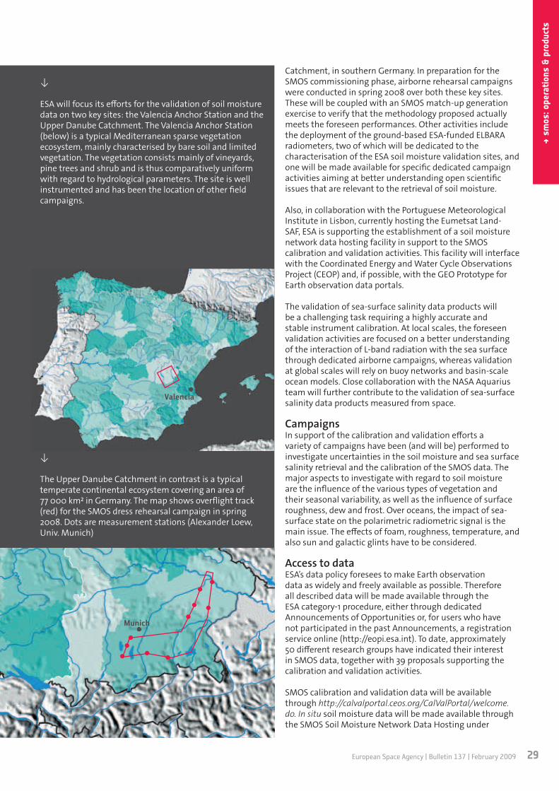
For the validation of the soil moisture data products, ESA’s activities will focus on two main sites, the Valencia Anchor Station, in eastern Spain, and the Upper Danube
29European Space Agency | Bulletin 137 | February 2009
→ sm
os: o
pera
tion
s &
pro
duct
s
Catchment, in southern Germany. In preparation for the SMOS commissioning phase, airborne rehearsal campaigns were conducted in spring 2008 over both these key sites. These will be coupled with an SMOS match-up generation exercise to verify that the methodology proposed actually meets the foreseen performances. Other activities include the deployment of the ground-based ESA-funded ELBARA radiometers, two of which will be dedicated to the characterisation of the ESA soil moisture validation sites, and one will be made available for specific dedicated campaign activities aiming at better understanding open scientific issues that are relevant to the retrieval of soil moisture.
Also, in collaboration with the Portuguese Meteorological Institute in Lisbon, currently hosting the Eumetsat Land-SAF, ESA is supporting the establishment of a soil moisture network data hosting facility in support to the SMOS calibration and validation activities. This facility will interface with the Coordinated Energy and Water Cycle Observations Project (CEOP) and, if possible, with the GEO Prototype for Earth observation data portals.
The validation of sea-surface salinity data products will be a challenging task requiring a highly accurate and stable instrument calibration. At local scales, the foreseen validation activities are focused on a better understanding of the interaction of L-band radiation with the sea surface through dedicated airborne campaigns, whereas validation at global scales will rely on buoy networks and basin-scale ocean models. Close collaboration with the NASA Aquarius team will further contribute to the validation of sea-surface salinity data products measured from space.
CampaignsIn support of the calibration and validation efforts a variety of campaigns have been (and will be) performed to investigate uncertainties in the soil moisture and sea surface salinity retrieval and the calibration of the SMOS data. The major aspects to investigate with regard to soil moisture are the influence of the various types of vegetation and their seasonal variability, as well as the influence of surface roughness, dew and frost. Over oceans, the impact of sea-surface state on the polarimetric radiometric signal is the main issue. The effects of foam, roughness, temperature, and also sun and galactic glints have to be considered.
Access to dataESA’s data policy foresees to make Earth observation data as widely and freely available as possible. Therefore all described data will be made available through the ESA category-1 procedure, either through dedicated Announcements of Opportunities or, for users who have not participated in the past Announcements, a registration service online (http://eopi.esa.int). To date, approximately 50 different research groups have indicated their interest in SMOS data, together with 39 proposals supporting the calibration and validation activities.
SMOS calibration and validation data will be available through http://calvalportal.ceos.org/CalValPortal/welcome.do. In situ soil moisture data will be made available through the SMOS Soil Moisture Network Data Hosting under
↓
ESA will focus its efforts for the validation of soil moisture data on two key sites: the Valencia Anchor Station and the Upper Danube Catchment. The Valencia Anchor Station (below) is a typical Mediterranean sparse vegetation ecosystem, mainly characterised by bare soil and limited vegetation. The vegetation consists mainly of vineyards, pine trees and shrub and is thus comparatively uniform with regard to hydrological parameters. The site is well instrumented and has been the location of other field campaigns.
↓
The Upper Danube Catchment in contrast is a typical temperate continental ecosystem covering an area of 77 000 km in Germany. The map shows overflight track (red) for the SMOS dress rehearsal campaign in spring 2008. Dots are measurement stations (Alexander Loew, Univ. Munich)
Munich
Valencia

www.esa.int30
eart
h ob
serv
atio
n
development at the University of Lisbon. ESA campaign data are available via the campaign database http://earth.esa.int/campaigns and through the SMOS Cal/Val portal.
WISE 2000/2001
LOSAC
FROG
SMOSREX
COSMOS-2006
SEA-ICE
SEA-ICE
DOMEX
EUROSTARRS 2001
COSMOS-2005
Demonstrator 2007
Ocean salinity airborne campaign in 2001, with L-band radiometer EMIRAD from Technical University of Denmark, several flights with variable wind conditions; discovery of ‘wiggles’, investigating azimuthal dependence of the two first Stokes parameters
Foam Rain Oil Slicks and GPS reflections in 2003, measuring L-Band polarimetric emission under controlled (foam and rain) conditions (campaign not funded by ESA)
Surface Monitoring of the Soil Reservoir Experiment near Toulouse (campaign not funded by ESA)
Airborne campaign in Norway (Norwegian Sea) in 2006 to acquire data under different ocea-nographic conditions for sea-surface salinity retrieval
Airborne campaign in the Gulf of Bothnia (Finland) in March 2007 to acquire L-band measure-ments over sea ice and test the retrieval of ice types and ice thickness
Airborne campaign in April 2008 over the key soil moisture validation sites of SMOS, in Ger-many and Spain
Tower-based radiometric measurements in Antarctica, calibration of brightness temperature over the Dome Concordia area
US Salinity Temperature and Roughness Remote Scanner (STARRS) was exploited during airborne campaign over France and Spain in 2001 providing airborne L-band observations over large areas
Airborne campaign in cooperation with the Australian’s National Airborne Field Experiment (NAFE 05) at the Goulburn River Catchment in November 2005; site extensively monitored and studied for soil moisture
Airborne campaign in August 2007 to perform dual-pol measurements and assess absolute accuracy of HUT2D, the interferometric radiometer of Helsinki University of Technology, and demonstrate the retrieval of a sea-surface salinity gradient off the coast of Helsinki
Wind and Salinity Experiment in 2000, at offshore oil drilling platform near Barcelona to pro-vide multi-angular polarimetric brightness temperature under different wind/wave conditions
↓
SMOS Campaigns: ESA campaign data are available via the campaign database http://earth.esa.int/campaigns and through the SMOS Cal/Val portal
→
Sea-surface salinity (SSS) retrieved using the L-band radiometer EMIRAD across a salinity gradient in the Norwegian Sea during the Cosmos-2006 airborne campaign. The blue and green curves show data retrieved by ferries crossing from Stavanger to Newcastle in April 2006
SSS
[psu
]
Longitude

Do you want to be part of the space future?
HE Space Operations strives to be the largest and most sought after on-site space knowledge provider in Europe.
Do you want to be part of this?
Send us your CV!Or check out our current jobs at
Astronomy
EngineeringOperations Software
Science Support Project Management
PR & Education Quality Assurance
HE Space Operations BV · Call: +31 71 341 7500 · [email protected] HE Space Operations GmbH · Call: +49 421 430 4230 · [email protected]
C
M
Y
CM
MY
CY
CMY
K
HE_Space_Advert_ESAInHouse_fullbleedA4_090116.ai 1 63.25 lpi 71.57° 16.01.2009 13:46:01HE_Space_Advert_ESAInHouse_fullbleedA4_090116.ai 1 63.25 lpi 18.43° 16.01.2009 13:46:01HE_Space_Advert_ESAInHouse_fullbleedA4_090116.ai 1 66.67 lpi 0.00° 16.01.2009 13:46:01HE_Space_Advert_ESAInHouse_fullbleedA4_090116.ai 1 70.71 lpi 45.00° 16.01.2009 13:46:01Prozessfarbe CyanProzessfarbe MagentaProzessfarbe GelbProzessfarbe Schwarz

↓
Artist impression of Space-QUEST: distribution of pairs of entangled photons using the International Space Station (ISS)

33European Space Agency | Bulletin 137 | February 2009
→ qu
antu
m c
omm
unic
atio
ns
→ LEAP AhEAd in SPAcE commUnicATionS
Josep Perdigues-Armengol & Zoran SodnikDirectorate of Technical and Quality Management
ESTEC, Noordwijk, The Netherlands
Clovis De MatosStrategic Planning and Strategic Control Office
ESA HQ, Paris, France
Quantum physics has changed our understanding of the fundamental principles of nature. Its predictions, although intriguing and counterintuitive, have been verified
Quantum technologies for space systems
extensively and have established quantum theory as one of the most successful theories of modern science. Quantum physics has reached a crucial stage where useful commercial and technological applications can be developed, based exclusively on quantum physics principles with no equivalent classical counterpart. These new and innovative technologies are called ‘quantum technologies’.
For a number of years, ESA has been examining how quantum technologies may benefit space applications and research. Indeed, it is expected that quantum
Today, spacecraft communicate with Earth using radio waves and laser beams but what about the future? ESA scientists believe that the weird behaviour of nature on its smallest scales may allow spacecraft to send information to Earth more securely and efficiently than ever before.

www.esa.int34
tech
nica
l
technologies will progressively enter the space arena and have a major impact on how we communicate or process information, as well as on how we will use the space environment in scientific missions to enhance our understanding of fundamental physics. One area that looks particularly promising for space application is ‘quantum communications’. In the future, this will become a novel type of resource available to a wide variety of space and ground systems.
At nature’s tiniest scales, non-intuitive things happen and these are known as quantum effects. For example, a beam of light can behave like an avalanche of particles, known as photons. Single photons cannot be cloned or split and, by measuring them, you change them from their initial state. So a message sent by a quantum communications system can only ever be read once because, as soon as it is read, the
→ Why quantum communications?
Security services are critical to modern telecommunications. For instance, they help ensure that a message received is the one that was sent, and that secrets remain secret.
The most sensitive information, such as bank transfers or military communications, can be encrypted very effectively. But some widely used encryption systems could be defeated by powerful computers,
and even if information is encrypted, an eavesdropper can still tap into a conventional communications channel and listen to or copy a transmission without being detected.
Quantum mechanics offers the potential for ultra-secure communications because the act of observing an unknown quantum system changes its state. As a consequence, accurate copying is
impossible, and changes caused by eavesdropping can be detected. Whereas today’s fibre-optic communication systems require bits of information made of thousands of photons, quantum communication uses single photons to transmit unique random secret keys of ones and zeros. These can be used in future secure encryption systems.
original message is automatically scrambled. This means that the receiving station can recognise if a third party has eavesdropped on the message.
These properties make possible the communications protocol called ‘quantum key distribution’, to distribute keys for data encryption with absolute security. If such a system was included in future versions of European’s global navigation system Galileo, for example, it would instantly show if someone had tampered with the signals to and from the satellites.
Another example of quantum communications protocol is called ‘quantum dense coding’, which uses the weird quantum phenomenon of ‘entanglement’ to put more than a single piece of information on each photon, increasing the capacity of the communication channel.

35European Space Agency | Bulletin 137 | February 2009
→ qu
antu
m c
omm
unic
atio
ns
→ Quantum ‘entanglement’ unravelled…
If two photons of light are allowed to properly interact with one another, they can become ‘entangled’. Pairs of entangled photons can even be created directly using a non-linear process called ‘Spontaneous Parametric Down Conversion’ (SPDC).
These two entangled photons can then be separated but as soon as one of them interacts with a third particle, the other photon of the pair modifies its quantum state. This happens according to the random outcome of the interaction, even
though this photon never actually interacted with the third particle.
Such behaviour has the potential to allow messages to be swapped with complete confidence. This is because, if an eavesdropper listens into the message, the act of detecting the photons changes the entangled partner. These changes would be obvious to the legitimate receiving station and the presence of the eavesdropper would be instantly detected.
Entanglement is one of the most puzzling quantum effects. If entanglement were possible on everyday scales, imagine having a pair of entangled coins. Give one to a friend and toss your coin. If you obtain a head, then you know immediately that when your friend tosses the other coin, it will fall on a tail. You do not have to wait for your friend to perform the experiment and tell you the result.
Understanding exactly how quantum particles are linked like this is difficult and some physicists never accepted the idea. Even Albert Einstein dubbed this effect as ‘spooky action’ and proposed that particles ‘hide’ some of their characteristics from us, which is why they then appear to spontaneously change their known ones.
Even though entanglement has been known about for decades, no one has known whether the entanglement
decays over long distance. For example, would a beam of entangled photons remain entangled if it passed through Earth’s atmosphere? On their journey, the photons could interact with atoms and molecules in the air. Would this destroy the entanglement? If so, entanglement would be useless as a means of communicating with satellites in orbit, because all signals would have to pass through Earth’s atmosphere.
In September 2005, a European team aimed ESA’s Optical Ground Station 1 m telescope on the Canary island of Tenerife toward the Roque de los Muchachos Observatory on the neighbouring island of La Palma, 144 km away. On La Palma, a specially built quantum optical terminal generated entangled photon pairs, using the SPDC process, and then sent one photon towards Tenerife, while keeping the other for comparison.
↙
ESA’s Optical Ground Station on the island of Tenerife (left), by day and night, with La Palma in distance at right and Mount Teide in background (T.Herbst)
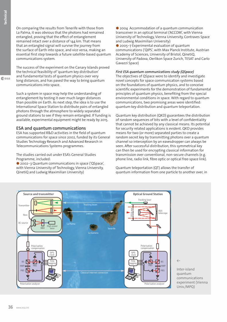
www.esa.int36
tech
nica
l
On comparing the results from Tenerife with those from La Palma, it was obvious that the photons had remained entangled, proving that the effect of entanglement remained intact over a distance of 144 km. That means that an entangled signal will survive the journey from the surface of Earth into space, and vice versa, making an essential first step towards a future satellite-based quantum communications system.
The success of the experiment on the Canary Islands proved the technical feasibility of ‘quantum key distribution’ and fundamental tests of quantum physics over very long distances, and has paved the way to bring quantum communications into space.
Such a system in space may help the understanding of entanglement by testing it over much larger distances than possible on Earth. As next step, the idea is to use the International Space Station to distribute pairs of entangled photons through the atmosphere to widely separated ground stations to see if they remain entangled. If funding is available, experimental equipment might be ready by 2015.
ESA and quantum communicationsESA has supported R&D activities in the field of quantum communications for space since 2002, funded by its General Studies Technology Research and Advanced Research in Telecommunications Systems programmes.
The studies carried out under ESA’s General Studies Programme, included:● 2002‒3 Quantum communications in space (‘QSpace’, with Vienna University of Technology, Vienna University, QinetiQ and Ludwig Maximilian University)
● 2004 Accommodation of a quantum communication transceiver in an optical terminal (‘ACCOM’, with Vienna University of Technology, Vienna University, Contraves Space and Ludwig Maximilian University)● 2005‒7 Experimental evaluation of quantum communications (‘QIPS’, with Max Planck Institute, Austrian Academy of Sciences, University of Bristol, QinetiQ, University of Padova, Oerlikon Space Zurich, TESAT and Carlo Gavazzi Space)
First ESA quantum communications study (QSpace)The objectives of QSpace were to identify and investigate novel concepts for space communication systems based on the foundations of quantum physics, and to conceive scientific experiments for the demonstration of fundamental principles of quantum physics, benefiting from the special environmental conditions in space. With regard to quantum communications, two promising areas were identified: quantum key distribution and quantum teleportation.
Quantum key distribution (QKD) guarantees the distribution of random sequences of bits with a level of confidentiality that cannot be achieved by any classical means. Its potential for security related applications is evident. QKD provides means for two (or more) separated parties to create a random secret key by transmitting photons over a quantum channel so interception by an eavesdropper can always be seen. After successful distribution, this symmetrical key can then be used for encrypting classical information for transmission over conventional, non-secure channels (e.g. phone line, radio link, fibre optic or optical free-space link).
Quantum teleportation (QT) allows the transfer of quantum information from one particle to another over, in
←
Inter-island quantum communications experiment (Vienna Univ./MPQ)
Source and transmitter Optical Ground Station
Transmitter
Tracking laser
OGStelescope
Polarisationcompensation
Polarisationcompensation
Polarisation analyserPolarisation analyser
fibre
DC source
BBOHigh power
laser
1016
mm
GPS clock
GPS clock
Timetagging
Timetagging
BSBS
HWPHWP
PBSPBS
PBSPBS
Classical internet connection
144 km
Tracking beam
La Palma
La Gomera
Tenerife

37European Space Agency | Bulletin 137 | February 2009
→ qu
antu
m c
omm
unic
atio
ns
principle, any distance. To perform QT it is necessary that transmitter and receiver share a pair of entangled photons. This connection via entanglement is usually referred to as a ‘quantum channel’, since there is no classical physical connection between transmitter and receiver (but only quantum correlations).
Note here though that matter and energy (and classical information) cannot be transferred from one place to another instantaneously, meaning that faster-than-light communications are not possible, since this would violate the rules of the theory of special relativity. Teleportation of quantum states is possible, but since QT requires classical communication, it is bounded by the speed of light.
Designing a quantum communications terminal (ACCOM)To demonstrate quantum communications in space, this investigation envisaged establishing free-space optical links between a space-based transceiver and several transceivers at ground stations separated by long distances.
To a large extent, much of space optical communications hardware is already available in Europe, so the main objective of the ACCOM study was to investigate the hardware needed for carrying out quantum communications experiments. Specifically, what adaptations were needed in a laser communication terminal to allow the integration of a quantum communication transceiver, which subsystems could be reutilised or removed, and which subsystems needed to be modified.
The design of a complete space-based quantum communications terminal was carried out (including classical and quantum subsystems), which could perform downlink as well as uplink quantum experiments. Existing
space-qualified and space-designed hardware (for example, telescopes, pointing/tracking mechanisms, acquisition sensors, etc.) was used.
The end result was a communications terminal, equipped with two telescopes, each with an independent pointing/acquisition/tracking subsystem capable of distributing entangled photon pairs from space towards two widely separated optical ground stations. The quantum communications transceiver included an entangled photon source, faint pulse laser sources, single photon detection modules and the associated optics for manipulating and analysing single photons.
Inter-island quantum link demonstration (QIPS)This study looked deeper into the designs of future mid-term and long-term experiments for demonstrating quantum communications applications, as well as fundamental principles of quantum physics in space. Both the scientific impact and the technical feasibility of the required space infrastructure were investigated.
To support these studies, basic ground-to-ground quantum communications experiments that represented the needs of space systems (i.e. very long distance links) were devised, in order to identify and evaluate the main critical areas of quantum communications. For example, how much is the quantum state or the entanglement of quantum particles affected when travelling through the atmosphere or in vacuum? Is there any distance limit for distributing entanglement between separated receivers?
This experiment would prove whether it was technically feasible to establish a single photon quantum channel (the transmission and detection of single photons) through long paths in the atmosphere, simulating a space-to-ground experiment in terms of total end-to-end link loss.
The Canary Islands (E) were chosen as location for the inter-island link to be established between a transmitter on the island of La Palma and a receiver on Tenerife. Both sites,
↑
Transmitter telescope on La Palma looking towards the receiver on Tenerife. One of the large aperture lenses transmits single photons; the other receives the beacon laser from Tenerife for tracking purposes (Vienna Univ./MPQ)
Quantum communications can play a key role in future space systems, in telecommunications, navigations and science.

www.esa.int38
tech
nica
l
operated by the Instituto Astrofisico de Canarias, are 144 km apart, and are higher than 2.3 km above sea level.
Before this experiment, the longest distance achieved by free-space faint pulse QKD was 23.4 km. Free-space entanglement based QKD had been demonstrated over 13 km. Using optical fibres instead of free space, faint pulse QKD had been tested at distances up to 150 km (although when considering potential eavesdropping risks, the maximum secure distance was only about 70 km). The inter-island quantum link experiment aimed at securely distributing quantum keys in free space at distances up to 144 km, which would become a world record.
The 144-km quantum channel established in this experiment represents a worst-case scenario for a space-to-ground link, due to atmospheric turbulence. The overall end-to-end transmission loss of this horizontal atmospheric link was 25‒35 dB, which is comparable to the link loss between a satellite in low Earth orbit and a ground receiver. Therefore, faint pulses, single photons and entangled photons used for QKD could in principle be distributed from space either to other spacecraft or to ground stations. An important aspect is that link loss only affects the key rate, not the confidentiality of the key. Quantum communications in space systemsQuantum communications can play a key role in future space systems, in telecommunications, navigation and science. Today, next-generation optical communication terminals (still based on classical optical communications) with reduced mass, size and power consumption, and increased data transmission rate are being considered by ESA for the implementation in the new European Data Relay System (EDRS).
The synergy between quantum communication transceivers and next-generation optical terminals would extend the range of applications beyond optical data relay. The capability of QKD is highly attractive for space applications where a very high level of security is necessary. Entanglement distribution might be of use in navigation, to improve the knowledge of satellite’s orbit parameters (quantum positioning), for time reference distribution and clock synchronisation, or it could be exploited in the very long-term to efficiently communicate with deep-space probes. These applications are presently under investigation.
Besides, space offers the possibility of ‘unlimited’ long paths in vacuum (with no absorption loss due to the atmosphere or optical fibres), and therefore is an ideal medium to experimentally push the limits of entanglement (if there are any). Taking entanglement into space opens the possibility to address fundamental scientific questions, such as what are the limits of entanglement and quantum physics? What is the meaning of realism and locality in nature? Are there natural sources of entanglement in the Universe? Are there special relativistic and general relativistic effects on quantum entanglement?
Towards a quantum experiment in spaceMoving into space enables photon entanglement to become a physical resource available for quantum experiments at a global scale. Many scientists want to test the theory of quantum physics over long distances and to establish a worldwide network for quantum communication, tasks that can only be realised by taking quantum physics into space.
In 2008, ESA initiated technology development activities to develop and increase the technology maturity level of the critical quantum subsystems, and also to explore additional quantum communications applications, in preparation for a future in-orbit demonstration.
A European research consortium led by Vienna University has submitted the Space-QUEST proposal to ESA, to develop a space-to-ground quantum communications experiment from the International Space Station. Alternative platforms are also being investigated.
The Space-QUEST experiment would be the first step towards the implementation of a World Wide Entanglement (WWE) service, and would accomplish the first-ever demonstration of QKD from space and fundamental tests on quantum physics, far beyond the possibilities of any ground-based experiment with current fibre optics and detector technologies.
Research groups in the United States and Asia are important players in the international race to bring quantum communications into space. However, with the success of the inter-island link experiment, European teams are a step ahead, and in cooperation with ESA, they are determined to keep this lead.
↑
Design of a complete space-based quantum communication payload

AT697 rad-hard SPARC® processor• 32-bit SPARC V8 LEON2-FT processor • High performance: 90 MIPs – 23 MFlops• Industry best power effi ciency: 150 MIPs/W• PCI interface• SRAM, (EE)PROM, SDRAM memory interface• Software compatible with other space SPARC
processors
• Standalone component • Radiation hardened
– Total dose: tested up to 300 Krad– Single Event Latchup immune– Extremely reliable against Single
Event Upset/Transient • QML Q/V – ESCC quality fl ows• MCGA 349/MQFP 256 pins packages
© 2008 Atmel Corporation. All rights reserved. Atmel®, logo and Everywhere You Are® are registered trademarks of Atmel Corporation or its subsidiaries. SPARC® is a registered trademark of SPARC International, Inc. Products bearing SPARC trademarks are based on an architecture developed by Sun Microsystems, Inc. Other terms and product names may be trademarks of others.
Everywhere You Are®
Get more info at: http://www.atmel.com/products/radhard/
Everywhere You Are®
100 MHz
operation
for only 0.7W
Atmel rad-hard integrated circuits for space include:
• ASICs up to 5 Million gates• Re-programmable FPGAs• Standalone and embedded processors• SpaceWire products• SRAM and EEPROM memories
The development of this processor has been supported by the European Space Agency.
Atmel_ESA_ad_last.indd 1 6/9/2008 4:21:50 PM

41European Space Agency | Bulletin 137 | February 2009
→ fu
ture
laun
cher
s
→ A ToUchSTonE for SUccESS
Guy RamusatFuture Launchers Preparatory Programme (FLPP), Directorate of Launchers, ESA HQ,
Paris, France
Large numbers of spacecraft manufacturers worldwide rely on the healthy and competitive European expendable launcher vehicle fleet – namely Ariane-5 and soon Soyuz and Vega – to successfully transport their various payloads into space.
However, in general, these commercial launch vehicles are based mainly on ‘conventional’ rocket technology. Today’s
core technology activity for future launchers
expendable launchers have reached a ‘plateau’ in terms of technical implementation and cost per flight.
Novel technological solutions, which cope with the ever-changing environmental loading conditions from launch until to payload delivery in orbit, are required to improve performance and reduce the cost of access to space, while still keeping high reliability.
Since the beginning of the 1990s, and backed up by a long-term vision, ESA has performed several trade studies to identify and assess new and innovative approaches or concepts for advanced as well as reusable launch vehicle systems. However, these attempts have never yielded development programmes, due to the changing market requirements and funding issues.
In 2004, together with several ESA Member States and European industry, ESA agreed to forge ahead with projects
Whether you’re going into Earth orbit, exploring distant worlds, or coming back home, the first and last few hundred kilometres of the journey are always the toughest part. The Core Technology project of ESA’s Future Launcher Preparatory Programme is helping to prepare future access to space, and make it cheaper, safer and more flexible than today.

www.esa.int42
lauc
hers
elements as well programmatic ones to make an informed decision in the future on the best operational launch vehicle system to respond to the future institutional needs, while maintaining competitiveness on the commercial market at that time.
This innovative and flexible programme has been investing in the development of industrial launcher technology capabilities in some main transatmospheric and space cargo transportation areas since 2004. How well ESA does this will be a major determining factor in Europe’s effectiveness in providing for this assured access to space in the future.
Past and current European programmes developed the Ariane, Vega and Soyuz at CSG launch vehicle assets, as
to assess next-generation launcher concepts, to look at European current situation and to foster future prospects in this field. The Future Launchers Preparatory Programme (FLPP) currently evaluates the development provisions required to design and build these future launchers for the most critical technologies in relation with the system studies.
Over the past 50 years, large budgets were spent worldwide on technology development programmes to dramatically increase the launch vehicle performances, to reduce costs and to provide safer and more reliable access to space. New system studies and associated technology capabilities are essential elements to support future Earth-to-orbit transportation developments, allowing the reduction of both development risk and associated costs.
Statistics based on 30 years of NASA civil space programmes argue in favour of the fact that investment spent in technology and the definition phases had actually reduced cost overruns. During those 30 years, ‘no project enjoyed less than a 40% cost overrun unless it was preceded by an investment in studies and technology of at least 5 to 10% of the actual project budget’, and a strong prior investment in such areas invariably tended to lower the cost overrun. Such results have also been confirmed by US military programmes.
At ESA agency level, the establishment of plans for advancing the development of critical technologies are considered as well as the introduction of technology readiness reviews for projects, in connection with System Requirement Reviews (SRRs), allowing a better identification and mitigation of technology risks. This reflects the importance of the technologies in the preparatory activities.
Representing a sizeable European investment, the general objective of the FLP Programme is to prepare these technical
↑
Prior investment invariably teads to lower cost overruns, as found in US Space programmes (W. E. Hammond - Space Transportation, A System Approach to Analysis and Design - AIAA series, 1999)
0
20
40
60
80
100
120
140
160
180
0 5 10 15 20 25
Perc
ent c
ost g
row
th o
f pro
gram
mes
Phase A/B investment % of programme total
→ industrial Policy
The FLP Programme is an ESA optional programme, where 13 Member States are participating, with a balanced subscription between the three major contributors (France, Germany and Italy). The industrial organisation, where new industrial schemes are implemented, reflects this configuration.
NGL Prime SpA, a joint venture of EADS SPACE (70%) and Finmeccanica (30%), has the responsibility, with
their subcontractors, for the NGL system activities, the management of several technologies and is responsible for the overall Technology Development and Verification Plan.
The Joint Propulsion Team, a consortium of EADS Astrium Space Transportation GmbH, Avio SpA and SNECMA, is responsible, with their subcontractors, for main stage propulsion technologies and
the related High-thrust Engine integrated demonstrator.
More than 60 companies, institutes or universities are involved in these activities. The programme benefits from this large industrial effort, where subcontractors can be involved early in system studies for trade-offs, and organisations not currently working on ESA-developed launchers can promote their know-how for future involvement.


www.esa.int44
lauc
hers
well as the required systems and industrial competencies in this field. However, to maintain these competencies, and a competitive European position, more-challenging programmes have to be put in place.
The technological know-how in all launch vehicle fields cannot be considered as something ‘once gained and never lost’, especially because Europe must respond to the future institutional launch vehicle requirements and be able to compete in the strong commercial market.
On the other hand, it not wise to depend on as-yet-unavailable technology to reach a fixed schedule and cost in a future launch vehicle development programme. The FLPP Core Technology project, with its various subsystem demonstrators, will demonstrate feasibility and answer the
Through technology, the FLPP is also an opening for new entrants to the launchers sector. As such, the whole FLPP programme will contribute to unleashing the true potential of space to the long-term benefit of the European citizens and the industry of ESA Member States.
Snapshot of FLPP activitiesThe preparation of these technical and programmatic elements is based on the maturation of enabling technologies that will mitigate risks in any future space transportation system development. The Period-1 of FLPP, which was decided in 2003 and is covering the years 2004-6, was focused on system studies and technology developments for the preparation of the Reusable Launch Vehicles (RLV) for the Next Generation Launcher (NGL).
The second period of FLPP was adopted in 2005 and is now under way. The contents of this second period have been oriented towards Expendable Launch Vehicles (ELV). A first step was adopted in 2005 and Step 2 was approved at the ESA Ministerial Council in November 2008, with the objectives to continue for the preparation of the NGL for the distant future, and to contribute to the preparation of short/medium-term decisions.
The programme implements a system-driven approach, largely addressing integrated demonstrators, as the most efficient way to increase the technology readiness level and address at the same time system-level capabilities, motivating and federating industry teams and capabilities behind concrete technological end-products, from their initial definition to their manufacturing, ground/flight testing and exploitation of results. Various launch vehicle system concepts (NGL or other advanced concepts) target an initial operating capability between 2025 and 2035, depending on the type of vehicle eventually selected for development. Aside from launch vehicle system concepts
↑
System studies on various Expendable Launch Vehicle concepts, baselines for technology activities (NGL Prime)
question for each concept: “Does the technology for a Next Generation Launcher exist, or is it within reach?”
The technology activities already carried out over FLPP Period 1 show that the technology assumptions are achievable. Whether the current FLP Programme is a success or not will depend on the follow-up applications. For instance, the technology improvement of the ceramic shield elements will support future re-entry vehicles and the FLPP Expander Engine Demonstrator activity led yet to a building block application in the post-Ariane ECA programme.
With the technical support of the ESA’s European Space Technology and Research Centre (Noordwijk), as well as European national space agencies and research organisations, the FLPP Core Technology project enables ESA to capitalise on launcher technology as one of the steps to prepare for future cheaper, safer and more flexible access to space.
←
Cross-section view inside a typical future launcher. Several key technologies are required to develop such a high-performance launcher (NGL Prime)

45European Space Agency | Bulletin 137 | February 2009
→ fu
ture
laun
cher
s
and configurations, the areas of liquid propulsion for main stages and upper stages, cryogenic issues for upper stages and atmospheric reentry are also being investigated in the frame of FLPP (see Bulletin 123, August 2005), at the levels of either technology or integrated demonstrators (e.g. the IXV for reentry technologies and the High-thrust Engine Demonstrator for main stage propulsion technologies, see Bulletin 128, November 2006).
Technology constituents of FLPPCurrent FLPP technology demonstration activities focus on various technologies and integration methods to improve reliability and reduce design cycle time, to refine analytical techniques, to increase robustness, to provide assessments which will yield high-fidelity information early in the design process, and all in order to derive cost-effective technologies for launchers. Some of the technologies developed in this activity may find application in the short and medium terms on evolutions of the current ESA-developed launchers.
Chemical rocket propulsion technology activities represent a large part of these technology activities (see Bulletin 134, May 2008). Beside the propulsion activities, the FLPP Core Technology theme is structured to cover subsystems for the NGL ELVs and to a lesser extent, as part of Period 1 activities, RLVs future developments. This area of the FLPP programme is the result of a multidisciplinary approach, based on a technology logic and ‘roadmap’ (TDVP), and research as well as development and testing of technology demonstrations which are carried out to achieve a ‘minds on’ (system-driven) and ‘hands on’ (integrated demonstrator) maturation approach of the various enabling technologies. In addition,
the programme framework assures that the technologies have maximum application owing to synergy with the other activities of FLPP. To close the loop, the concepts studied by the system rely to varying degrees on the development of technologies that are needed to mitigate architecture risk.
The FLPP Core Technology portfolio includes major challenges in the numerous technical areas relevant to launch fabrication to mastering materials, processes, design and structures, avionics, pyrotechnics, aerodynamics and aerothermodynamics issues, health monitoring, ground test facilities, etc. Part of these activities is also dealing with investigations in promising technologies at early stage of maturation that might lead to potential technical breakthroughs.
The improvements of individual technologies, as well as sub-system integrated technologies, are assessed according to the Technology Readiness Level (TRL) scale. The TRL (from 1 to 9) index ranking is set up for each product/subsystem based on various parameters, such as materials/components characterisation and availability, processes maturity, type of element, element analysis, and element verification environment.
The accomplishmentsStructures, materials and processes technologyDue to the unique requirements of launch vehicles, the overall structural architecture – including tanks, structures and thermal protection – must achieve, as a design goal, the lowest mass possible compatible with the combined mechanical, thermal and fatigue loads and cost objectives. Major challenges include reducing overall structural mass, manage structural margins for robustness, containment of cryogenic hydrogen and oxygen propellants, reusable thermal protection system for RLV, etc.
Future launch vehicle requirements, for instance in upper-stage structures, will require higher structural efficiency which in turn will need investigations into new materials and new processing technologies. Emerging technologies that can significantly reduce the dry mass are studied in the programme. The leap in technology is the development of low specific mass materials and stiff structures that can withstand high stresses. This development of these advanced materials and processes must be carried out well ahead of the design phase.
Optimisation of design, using non-conventional structural concepts and investigation of characteristics associated with future in-orbit manoeuvres, will introduce improvements that can initially verified on representative vehicle structural models. These structural demonstrations will have to follow concepts and system requirements defined during the system phase of the programme.
Carbon-fibre reinforced polymer (CFRP) structures The latest conceptual designs for reusable space transportation systems require unprecedented and very large lightweight metal and composite airframe structures.
↑
Automatic isogrid CFPR panel construction (EADS CASA Espacio)

www.esa.int46
lauc
hers
An investigation and characterisation of a reusable bismaleimide (BMI) resin-based CFRP structure was performed in high-temperature and harsh environment conditions, using an isogrid stiffened intertank panel demonstrator manufactured with an automated facility, and a wing box type structure. Optical fibre sensors were integrated in the test demonstrators to monitor potential damage during cyclic testing. This represents a step forward towards large unpressurised lightweight CFRP structures.
The heat transfer from hot spots to the surrounding composite structure was investigated with CFRP panel combining heavy load and high temperature resistant properties.
Thermal Protection Systems (TPS) and hot structuresThe reusable NGL system concepts studies and IXV development have spurred technology activities related to structures used in harsh environment. These activities were carried out in order to validate dedicated critical ceramic and metallic TPS architectures as well as ceramic matrix composites (CMC) hot structures. Vehicle trajectory peak heat flux and dynamic pressure dictate the TPS shingle outer surface material. Heat loading decides the thickness of the insulation material stack. Before being applied to future operational developments, these subsystems were defined through computational fluid dynamics (CFD) methods, plasma wind-tunnel tests and in-flight experimentations. The demonstrator structural integrity verifications are benefiting from the existing European high-temperature mechanical testing chambers and plasma flow facilities.
A variety of reusable TPS concepts are being developed and verified in this programme, addressing the requirements of future hypersonic vehicles. Selection of the optimum TPS for a particular vehicle is a complex and challenging task that requires consideration of not only mass, but also operability, aerodynamic shape preservation, maintenance with rapid turnaround capabilities, durability, initial cost, life-cycle cost, and integration with the vehicle structures, including cryogenic propellant tanks.
Based on a European heritage, three main families of ‘passive’ TPS are generally considered to achieve the required goals of future operational lift/drag efficient orbit-to-Earth reusable hypersonic vehicles, namely: metallic panels, rigid CMC shingles and flexible ceramic blankets.
Reusable launch vehicles also require highly loaded structural components, exposed to medium to high heat fluxes. Examples of these components are nose caps, leading edges of wings, body-flaps, ailerons, flaps and rudders.
Cryogenic upper-stage activitiesThe activity concerning the cryogenic upper-stage technologies is part of the system-driven technology development approach implemented within the FLPP. This approach ensures consistency at launcher system level between: (i) launcher system concept definition and selection activities and (ii) several lines of launcher technology developments in propulsion, materials and structures, and upper-stage cryotechnologies carried out under separate activities and performed in parallel by different industrial teams.
The activity identifies and develops critical technologies, enabling versatile missions and improving the performances of a reignitable cryogenic upper stage. The cryotechnology
→ We are not alone!
One of the main roles of ESA is to consolidate space activities in Europe, drawing on all expertise of the Member States to realise a common vision. This is done by coordinating the technical activities of Member States’ national agencies, technical centres and research institutions, and by optimising
and distributing work approved at Programme Board level.
ESA strengthens the levels of technical competences by avoiding duplication, by managing investments in a cooperative way and at the same time bearing down on industrial activity cost.
In applying this scheme, the FLPP Core Technology project also relies on the support, for example, of Italian space agency’s technical centre CIRA, the French centres at CNES Evry and Toulouse and German DLR centres.
does the technology for a next generation Launcher exist, or is it within reach?

47European Space Agency | Bulletin 137 | February 2009
→ fu
ture
laun
cher
s

www.esa.int48
lauc
hers
project is organised in three parts: (i) activity dedicated to critical technologies selection, (ii) activity targeting the technology development to reach TRL5/6, and (iii) in-flight demonstration of gravity-dependent technologies.
On the other hand, the inert mass of an upper stage has a direct impact on launch vehicle performance. To maximise the payload mass, the upper stage must use lightweight structural concepts to improve the mass fraction of the stage. Therefore, it is critical that tailored and appropriate criteria and margins are used. For that reason, this technology activity is designed to demonstrate, through analysis and ground demonstrations, that system level and technology improvements of an advanced material tank wall system and innovative upper-stage primary structure and mechanisms can lead to mass decrease, cost efficiency and robustness, improved margins and operational flexibility of a reignitable expendable upper stage.
Avionics/health monitoringAdvanced avionics architecture will be required for all future launcher applications, providing the processing capability for the mission and launch vehicle management, health management, guidance, navigation, and control functions.
Ariane 5 has a well-known avionics system. But new requirements or obsolescence will lead to the definition of new computer/avionics architectures, and to the development of new flight application software. The main critical avionics technologies are the digital architecture for on-board computers with their associated software, and data buses (including optical fibre support) to provide high data rates, as well as health monitoring. To take into account all these needs and cover all missions envisaged today (especially reentries), these new architectures should be as modular and scalable as possible, in particular for redundancy.
The activity consists in consolidating a technology roadmap, preparing associated means and defining further development work necessary to bring these technologies to an operational qualification level.
PyrotechnicsThis FLPP technology activity initiates investigations to develop innovative techniques using pyrotechnic subsystems in term of concepts, manufacturing and integration of key functions (such as engines and large rocket motor ignition, ground-to-launcher, stage-to-stage and launcher-to-payload separation systems, release functions and launcher neutralisation and safety), as well as a momentum and maturation of these techniques for applications outside the space industry (in cars or aircraft, for example).
The innovative pyrotechnics subsystems for future launchers will be based on two types: ‘electro-pyrotechnics’ and ‘opto-pyrotechnics’. Improvements of conventional pyrotechnics based on electro-pyrotechnics draw on the accomplishments and wide experience gained so far in Europe; these devices have been used on European launchers since Ariane 1 and have been proved reliable and safe with use through to Ariane 5. Such pyrotechnics have been taken up for the Vega launcher. However, to be competitive, electro-pyrotechnic subsystems and devices must be upgraded to meet future needs in terms of size, cost and environmental regulations.
Opto-pyrotechnics is a technology currently being evaluated worldwide as one of the key subsystems for the evolution of current launchers and future developments. These devices have the following advantages: reduced mass, recurring cost reduction (at both system and pyro-subsystem levels), improvements at Reliability, Availability, Maintainability, Safety level by the removal of primary explosives from the system, simplification of operations prior to launch, increase of safety, and immunity to electromagnetic interference and electrostatic discharge.
Densified propellantsFurthering European knowledge in slush hydrogen technologies, there is activity in assessing the feasibility and advantages of this type of propellant into the NGL concepts.
The advantages are due to the higher density and heat capacity that can be achieved by adding a solid fraction to liquid hydrogen. However this mixture presents a number
←
FLPP covers the whole range of advanced technologies involved in launcher design: structures, pyrotechnics, propellant, reentry aerodynamics, for example.

49European Space Agency | Bulletin 137 | February 2009
→ fu
ture
laun
cher
s
and analysis of the launcher itself. Aerodynamic analysis of any trans-atmospheric vehicle requires a database with both static and dynamic derivatives. However, conventional wind tunnel facilities cannot duplicate flight conditions for: (i) the hypersonic regime as the state of the flow field upstream of the model is not representative, the gas is partially dissociated when reaching the test section, or (ii) lower Mach numbers, where the aerodynamic coefficients are affected by the structure of the flow field in the wake.
The presence of a string holding the model disturbs the duplication of wake flow phenomena, which govern the stability behaviour. An advanced method to generate these coefficients is being investigated, based on an experimental method of free-flight stability assessment of vehicles where the model is moving into ambient gas at rest. The model can move freely around all axes, under correct influence of forces and damping. In addition, information on the detailed flow structure can be obtained (e.g. shock impingement and control surfaces).
Up to now this test method has been used for ballistic bodies, providing direct contributions to the aerodynamic database and also valuable data for code calibration. Of particular relevance are the studies of unsteady base flows as well as buffeting phenomena for the aft sections of launchers, the studies of separation events and of deployments.
of issues that still need to be resolved to make it a practical potential propellant for future space transportation.
The activity performed under FLPP is based on a promising ‘snow-gun’ preparation method, demonstrated at laboratory scale. The proposed work will be dedicated to the topics dealing with improvement of slush hydrogen production facilities measurement devices development, characterisation of stored slush (i.e. particles size over time, particle settling velocity), slush transfer (i.e. expulsion from tanks, flow through pipes and valves), long-term storage issues. The Critical Design Review of the pilot plant took place recently.
Parallel system studies were conducted to assess launch vehicle concepts based on combinations of densified propellants. Based on concurrent engineering activities, these preliminary investigations provided positive results; the use of densified propellants in existing launchers may give a payload mass increase between 2% and 10%, depending on the densification level, the application stage and the target orbit. Application to upper stages is easier (less propellant mass, less launcher modifications) and more effective (the structural mass fraction role is more important). The advantages and drawbacks related to the use of slush into propulsion systems have still to be evaluated further.
AerodynamicsPreparation of future technologies is not only limited to on-board systems, but also covers methods for the design
→ Plasma wind tunnels for reentry simulation
● Inductive Plasma Wind Tunnel, or ‘Plasmatron’ (VKI, Belgium)
Unpolluted plasma flows of any gas can be produced by inductive heating. This facility uses a high-frequency generator and torch to generate a plasma flow, and is mainly devoted to the testing of specimens of TPS materials to be used in the manufacture of shingles of the FLPP CMC TPS demonstrator.
● Scirocco Plasma Wind Tunnel Facility (CIRA, Italy)
This facility consists of an arc-heated gas generator and an expansion nozzle exhausting in a vacuum chamber. Air is injected from an upstream reservoir in the gas generator and heated as it flows through a constricted section by the electric arc established between the cylindrical cathode and the annular anode before expanding in the nozzle. The FLPP CMC TPS demonstrator was tested in this facility.
One of the most critical aspects of a space mission is the ‘reentry’, the return of a vehicle from orbit into Earth’s atmosphere. This hypersonic flight regime can be simulated with a wide range of ground-test facilities that duplicate aspects of atmospheric entry, such as total enthalpy and stagnation pressure for high altitudes.
↘
Test for IXV heatshield element in the Scirocco facility

51European Space Agency | Bulletin 137 | February 2009
→ ga
ia
→ ESA’S ‘BiLLion-PiXEL’ cAmErA
Philippe Gare, Giuseppe Sarri & Rudolf SchmidtDirectorate of Science and Robotic Exploration,
ESTEC, Noordwijk, The Netherlands
Indeed, when Gaia lifts off from ESA’s Spaceport in Kourou, French Guiana, by the end of 2011, it will be carrying the largest digital camera in the Solar System.
The challenges of the gaia mission
Combined with the simultaneously measured photometric and spectrometric information, the Gaia data set will provide a vast improvement of our knowledge of the early formation of our galaxy and its subsequent dynamical, chemical and star-forming evolution.
As it spins gently in its orbit, 1.5 million kilometres away from Earth, Gaia will scan the entire sky for stars, planets, asteroids, distant galaxies and everything in between. Conducting a census of over a thousand million stars, it will monitor each of its target stars up to 70 times over a
Gaia is ESA’s global space astrometry mission,designed to map one thousand million stars and hundreds of thousands of other celestial objects in our galaxy, so its camera will have to be something truly special.

www.esa.int52
scie
nce
Early technology development started in 2000, but by 2005 the level of confidence in these large-size CCDs was high enough that mass production could be envisaged. The same year, a procurement contract was placed with e2v technologies (UK) for the astrometric-type CCD and extended, in early 2006, to the ‘blue’ and ‘red’ types of CCDs (differences due to the wavelength range for which they are optimised).
Thanks to this early start, the production is now well ahead of the required dates for the satellite. About two thirds of the total amount of CCDs is already available for the spacecraft programme, this includes more than half of the flight-quality models. The sensitivity of CCDs to radiation in space was the most critical problem encountered to date (i.e. from solar activity such as solar flares or ‘coronal mass ejections’), and this was even considered a major ‘show-stopper’ for the whole mission if not adequately mitigated.
Astrium SAS, the prime contractor, proposed a comprehensive CCD test and characterisation programme. This programme was reviewed and accepted in close collaboration with the scientific community and is now in its
five-year period, precisely charting positions, distances, movements and changes in brightness.
The aim is to detect every celestial object down to about a million times fainter than the unaided human eye can see. To do that, it needs a large camera. In fact, there will be over 100 separate cameras in Gaia, tiled together in a mosaic to register every object that passes through the field of view. Scientists call each of these individual cameras ‘charge-coupled devices’, or CCDs.
Each CCD is itself a major piece of hi-tech kit that converts light into electrical charge and stores it in tiny pockets known as ‘pixels’ until the computer reads out this information. With about 1000 million pixels, Gaia’s focal plane is the largest digital camera ever built for spaceflight.
Progress made and difficulties overcomeGaia’s impressive task meant that several key technologies needed to be pushed forward significantly. The performance of some optical equipment, e.g. mirrors and detectors, was subject to specific technology developments but, in particular, the size of Gaia’s novel CCDs presented some unique manufacturing challenges.
Astrometry, the science of determining the position of objects in the sky, has been predominantly performed from Earth within the ‘narrow’ field of view of a telescope.
This method relies on measuring the apparent displacement over time of nearby stars compared to more distant reference stars. This displacement, known as ‘parallax’, is caused by the changing direction of view of an observer as Earth orbits around the Sun. The inherent
measurement errors only permit to achieve accuracies of the order of a milliarcsecond, thus three orders of magnitude worse than the expected Gaia accuracy.
Gaia’s technique is ‘wide-angle’ astrometry, which allows direct measurement of the absolute parallax. This technique is based on continuous star detections in two fields of view separated by a large angle which needs to be known and maintained at a very high accuracy
over the entire mission lifetime. This technique was successfully demonstrated on Hipparcos, ESA’s first astrometry mission, launched in 1989.
→ measurement principles of astrometry
Earth
Sun
1 a.u. 1 a.u.
Line of sight in July
Line of sight in
January
p
d=1/pp= parallax in arcsecondsd=distance to star in parsecs(1 parsec=3.26 light-years)
↑
ESA’s Hipparcos spacecraft
d

53European Space Agency | Bulletin 137 | February 2009
→ ga
ia
execution phase. Based on detailed analysis of early results, it is expected that the radiation effect can be calibrated and so removed from real measurements in space.
The associated data processing is currently in its design phase. The process will not be simple, because many CCD parameters need to be taken into account, but it should ensure that measurement accuracy is not impeded by radiation effects.
Many lessons have been learned during the CCD production; not only related to the development and validation of new CCD technologies, but also linked to the effort associated to the establishment of a ‘mass production’ for space hardware.
The most obvious lesson learned is that the production of new technology items must begin as early as possible, even before the spacecraft programme starts and must remain very closely linked to the spacecraft project. For Gaia, this early start means that the procurement and availability of the CCDs, initially considered to be the most critical activity, has been downgraded to a relatively smooth production process.
Despite several unexpected problems emerging during the CCD production phase, the associated healthy schedule meant that problems could be resolved with low stress and without excessive time pressure.
Gaia spacecraft and payload in detailGaia’s star measurement principle relies on the repeated observation of star positions in two fields of view. The spacecraft rotates slowly at a constant angular rate of 1 degree/min around the spin axis, therefore completing four great circles on the sky in one day. In addition, the orientation of the spin axis is modulated by a slow precession around the Sun-to-Earth line with a period of 63.12 days that enables the observation of about 70 transits
↑
The Gaia Payload Module. The focal plane is hanging on the ‘optical bench torus’ made of silicon carbide. The optics consist of 10 mirrors and the refractive optical elements. Mirrors M1, M2 and M3 form one telescope and M1’, M2’, M3’ the other telescope. The subsequent set of mirrors M4/M4’, M5 and M6 combine the light from both telescopes and direct it to the focal plane assembly. The fields of view are 106.5° apart (Astrium SAS)
of the same celestial object over the five-year mission duration.
The achievement of the final product of the mission, a catalogue containing the accurate position and true motion
→
The focal plane assembly. Each of the 106 CCDs has its own front-end electronics (Proximity Electronic Module). The detection plane is made up of 7 rows. Each one is served for power, clock and data distribution by one Interconnection Mod-ule. The thermal dissipation is purely passive. The mass of the focal plane assembly is 190 kg and the power consumption is 430 W (Astrium SAS)
Proximity Electronic Modules
CCDs
Interconnection Modules
Photometer Prisms
M1’
M1
M3’
M3
M2’
M2
M4M4’
M5
M6
Torus
Focal plane assembly

www.esa.int54
scie
nce
of about one thousand million stars, requires a complex space and ground infrastructure. The expected accuracy of the order of 10 to 300 microarcseconds, depending on the magnitude and colour of the star, calls for extreme mechanical and thermal stability of the spacecraft.
The Payload Module is thermally insulated and its optical bench and nearly all optical elements are made of silicon carbide, a material which offers an extreme stiffness combined with a very low coefficient of thermal expansion. The spacecraft will be placed in a ‘Lissajous’ orbit around the Lagrange point L2, about 1.5 million km away from Earth in the anti-sunward direction. This location offers a highly thermally stable illumination by the Sun.
The Payload Module consists of two telescopes separated by a ‘basic angle’ of 106.5° sharing the same focal plane. The ultimate astrometric accuracy is determined by the size of the telescope aperture and the total number of photons detected. Therefore, fundamental design criteria are:- mirrors M1 and M1’ as large as possible but still compatible with the size of fairing of the Soyuz launcher;- maximum transmittance of the optics and ‘quantum efficiency’ (i.e. the conversion efficiency of photons into electrons) of the CCD detectors; and - large focal plane to simultaneously maximise signal integration time and number of stars detection.
Thanks to these specifications, Gaia will collect ten thousand times more photons in its five-year mission than the Hipparcos spacecraft did for a comparable star. Gaia will be able to see stars a thousand times fainter than Hipparcos, down to magnitude 20.
The detection of these photons is performed with CCDs, and the focal plane assembly consists of 106 CCDs and individual front-end electronics. The CCDs are arranged in seven rows, and the signals from each row are collected by
Star Mappers (SM1/2)
AstrometricField
AF1–AF9
SpectroscopicField
(RVS1/3)
Photometric(blue & red)
Field
row 7
row 6
row 5
row 4
row 3
row 2
row 1
Star motion
↑
The CCD focal plane. The strips SM1 and SM2 are used for inital star acquisition. The strips AF1 to AF9 constitute the astrometric field for precision position measurement. The strips BP and RP allow spectral measurement in the range 330‒680 nm and 640‒1000 nm. The strips RVS1 to RVS3 allow fine spectroscopy in the range 847-874 nm (Astrium SAS)
0.93 m
an Interconnection Module that handles power, data and clock distribution.
The very compact packaging of the electronics creates real challenges regarding heat rejection, integration and accessibility to the units during ground testing. Active thermal control with heat pipes is not an option due to mechanical noise introduced into the Payload Module.
The detection planeOut of the 106 CCDs, 102 are dedicated to star detections and they are grouped into four fields: Star Mapper CCDs, Astrometric Field CCDs, Photometric Field (Blue and Red) CCDs and Spectroscopic Field CCDs (radial velocity measurement). A further four CCDs are used for monitoring the stability of the basic angle between the two telescopes and the quality of the optical performances.
As the two telescopes sweep the sky due to the spin of the spacecraft, the images of the stars in their respective field of view move across the focal plane. These images are seen first by the two strips of seven CCDs each, called Star Mappers. Each of the two strips is assigned to a telescope and detects star images only from that telescope.
Software classifies the signals detected by the Star Mappers either as stars (to be tracked in the following Astrometric Field) or as a ‘transient’ caused, for example, by a cosmic ray. In the latter case, the signal will be rejected. The software also allows a precise determination and control of the satellite’s spin rate.
↑
Simulation of a stellar field on the focal plane of Gaia and three 6x6 pixel windows assigned to detected stars. The content of the windows, after appropriate binning, is sent to the ground (Astrium SAS)
0.4
2 m
BP RP

55European Space Agency | Bulletin 137 | February 2009
→ ga
ia
The confirmed star images will then sweep over the Astrometric Field where they are get assigned tracking ‘windows’. Only the content of these ‘windows’ is transmitted to the ground. The windows are necessary to ensure that only useful information from each CCD is read out and treated by the subsequent star classification processes. The processing of each star image also requires a precise time-stamping by a rubidium atomic clock.
Next, the star images enter the Photometric Field where two low-resolution spectra are generated by dispersive optical elements. The first spectrum, the ‘blue’, is between 330 and 680 nm; the ‘red’ spectrum goes from 640 to 1000 nm. The spectra are dispersed over 45 pixels on the CCD and they
Star design density for sizing of the focal-plane control electronics and scientific software resources
Maximum number of simultaneous star detections which can be followed per CCD at any time
Maximum number of simultaneous star detections which can be processed by the CCD and control electronics per CCD per second
Maximum number of simultaneous star detections which can be followed in the astrometric focal plane at any time
Maximum number of simultaneous star detections which can be processed by the focal plane per second
750 000 stars/deg
5400 stars
1200 stars
334 000 stars
8400 stars
→
Basic detection and processing capabilities of the Gaia focal plane
are used for gathering colour information on the stars and correction of the chromatic aberrations in the astrometric part of the instrument.
Finally, the star images enter the Spectroscopic Field where a spectrograph only allows light in the narrow band of 847‒874 nm. The filtered light is then dispersed over 1100 pixels to detect characteristic spectral lines in the band. This allows, later on ground, the measurement of the red or blue shifts of the lines and the calculation of the stellar velocities in the radial (line-of-sight) direction. This part of the payload is called the Radial Velocity Spectrometer.
One of the enabling technologies to reach the required Gaia measurement accuracy is a long signal integration time and the detection of a large number of stars at the same time. This led to a focal plane of almost half a square metre, and hence the large-sized CCDs.
CCD operating modes and geometric characteristicsThe optical image of a star on the Gaia focal plane, the Point Spread Function (PSF), corresponds to a ‘charge cloud’ that extends over a few pixels on a CCD. Unlike a normal digital camera that takes pictures as a full frame, the Gaia ‘camera’ tracks the movement of a PSF across the CCDs. In short, not one single image of a star is taken but a continuous sampling of the image is made as it moves across the focal plane.
The CCDs operate in a ‘Time Delayed Integration’ (TDI) mode, where the photoelectrons generated by the star image are clocked across a CCD together with the moving star image. The amount of collected charge at the output of the CCD is proportional to the brightness of the star image and the time it needs to cross a detector. A star similar to our Sun, with a magnitude of 15, accumulates a total charge of about 90 000 electrons during the crossing of a CCD. The moving star image, i.e. at the spin rate of the satellite, has to match the clocking speed of the charge cloud across the focal plane. To this end the Gaia spacecraft is equipped with a novel ‘cold gas’ micropropulsion system.
↑
Four Astrometic Field (AF) CCDs mounted on their test jigs. The CCD is 45 x 59 mm with 8.8 megapixels. The associated field of view is 4.4 x 5.8 arcminutes. A star will take 4.42 seconds to cross the CCD (e2V technologies)

www.esa.int56
scie
nce
The relation between the size of the PSF and the size of the pixel of the CCD is fundamental for achieving the measurement accuracy. The focal length determines the size of the PSF on the CCD. It has to be long enough and the pixel small enough such that the PSF can be sampled with a sufficient number of pixels. On the other hand, the pixel must be large enough to avoid images of brighter stars to cause a local saturation on the CCD. The best compromise was found with a 35 m focal length and pixel sizes of 10 µm along the star-crossing direction and 30 µm perpendicular to it. The charge handling capacity of each pixel is about 190 000 electrons.
The objects observed will vary enormously in terms of brightness and size. The number of charges generated can vary from above a few million electrons for bright stars down to few electrons per pixels once spectrally dispersed in the spectroscopic field. Because at any given time there is a combination of faint and bright stars images on the focal plane, each CCD must be able to handle saturated pixels and allow modulation of the integration time. This leads to the implementation of an ‘anti-blooming’ function and ‘gates’ to adapt the integration time to the brightness of the star.
Furthermore, the readout register and output amplifier need to be capable of operating at very different frequencies. For example, the Star Mapper CCDs have to process all presumed star images in order to quickly select the correct ones for further monitoring in the subsequent fields. Astrometric Field CCDs deal with an already selected set of images and Spectrometer CCDs see a further reduction in useful signals. Thus, operating frequencies of the CCDs vary from a few tens of kilohertz for the spectroscopic field to about a megahertz for the Star Mappers. One of the outstanding features of the Gaia CCDs is an average noise level of less than six electrons in the output amplifier.
The physical size of the CCDs has been chosen to match today’s wafer technologies (5-inch/127 mm wafers) and to be in line with realistic production yields of the manufacturing company. The Gaia CCD features 4500 pixels in the along-scan direction and 1966 pixels in across-scan. The packaging of the CCDs is selected for maximum packing density and best thermomechanical properties, since the focal plane operates at about -110°C.
Radiation effects and implications for performanceIn space, the CCDs will be subjected to irradiation by energetic particles that have an impact on the long-term
↑
The Gaia CCD Support Structure. The structure is made by sintered silicon carbide which guarantees an extreme thermal and mechanical stability (Boostec Industries)
behaviour of these detectors. In particular, solar and cosmic background radiation generates defects in the detector crystal lattice, which can trap electrons and release them later. This effect is not good for the science of Gaia, since it changes the shape of the PSF of a star image and interferes with the highly accurate determination of the maximum value of the PSF. The radiation causes the following effects:
- Charge loss in the PSF of typically 20% at the radiation dose accumulated at the end of the Gaia mission. This affects the astrometric, photometric and spectroscopic measurements as all three depend on the number of collected photoelectrons.
- Bias of the uncorrected star position measurement of typically 0.16 pixels (10 milliarcseconds) at the end-of-life radiation dose. This is a consequence of electron trapping and delayed release. This affects astrometry, photometry and spectroscopy by shifting the spectral lines and mixing up wavelengths.
- Release of trapped electrons could happen while subsequent star images transit the releasing traps. Electrons would be added to the PSF, which is comparable with the effect of stray light in the telescope.
Breadboard models
Engineering models
Astrometric CCDs Blue-enhanced CCDs Red-enhanced CCDs
Flight models and spares
11 1 1
20 3 8
94 10 26
↘
CCDs manufactured for the Gaia development and flight programme

57European Space Agency | Bulletin 137 | February 2009
→ ga
ia
Astrometric CCDs
Blue-enhanced CCDs
Evaluationtesting
Constructional analysis
Environmental/mechanical
Assembly/capability Endurance DPA
Red-enhanced CCDs
2 10 Performed as part of the DPA
212
1
4 for irradiation.Vibration/shock testing and temperature cycling evaluated by similarity with astrometric CCD
Performed as part of the DPA
13
1
4 for irradiation.Vibration/shock testing and temperature cycling evaluated by similarity with astrometric CCD
Performed as part of the DPA
13
Shortly after the start of the overall spacecraft development programme in 2006, a systematic test campaign was initiated with irradiated CCDs. These tests are still ongoing at Astrium SAS. The tests, as well as the analysis of intermediate results, were carried out to: understand the radiation bias process; provide a quantitative assessment of its effect on astrometry, photometry and spectroscopy; investigate the benefit of electronic charge injection and other mitigation possibilities; and derive an algorithm to systematically correct the data stream for the radiation effects.
The ongoing tests are also used for the detailed theoretical modelling of the radiation effects, and will consolidate the strategy for removing the radiation effects from the scientific measurements. Given the criticality of the issue for the Gaia mission, the test campaign is conducted in close cooperation between the industrial prime contractor, the ESA project team and the scientific community.
Manufacturing, performance testing and qualification testingAll CCDs populating the focal plane have the same format and, in principle, the same function. Some differences exist due to the wavelength range for which they are optimised. Three different CCD types were developed: the astrometric, the ‘red-enhanced’ and the ‘blue-enhanced’.
The only difference between the astrometric CCD and the ‘blue’ CCD is the additional anti-reflection coating optimised for maximum quantum efficiency at the chosen wavelength. The ‘red’ CCDs are manufactured from high-resistivity silicon. The thickness of this detector is 40 µm for enhanced quantum efficiency instead of the 16 µm used for the other two CCD types.
↑
Gaia’s photometric and spectrometric CCDs: top, the red photometer and, below, the blue photometer. These CCDs are variations of the astrometric CCD to enhance perform-ances in the blue and red parts of the optical spectrum. The red CCD is blue in colour because it absorbs red light and reflects blue (e2V technologies)
↑
Summary of CCDs allocated for project evaluation tests, with a total of 40 devices used (DPA = destructive physical analysis)
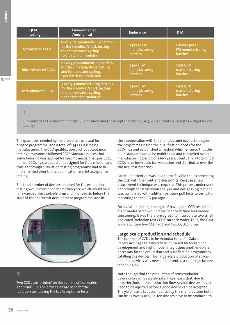
www.esa.int58
scie
nce
close cooperation with the manufacturer e2v technologies, the project reassessed the qualification needs for the CCD91-72 and established a method which ensured that the build standard would be maintained and controlled over a manufacturing period of a few years. Eventually, a total of 40 CCDs have been used for evaluation and distributed over the classical test branches.
Particular attention was paid to the flexible cable connecting the CCD with the front-end electronics, because a new attachment technique was required. This process underwent a thorough constructional analysis and out-gassing test and was completed with cold-temperature pull tests to verify its mounting to the CCD package.
For radiation testing, the logic of having one CCD tested per flight model batch would have been very time and money consuming. It was therefore agreed to incorporate two small dedicated ‘radiation test CCDs’ on each wafer. Thus, the Gaia wafers contain two CCD91-72 and two CCD221 dices.
Large-scale production and scheduleThe number of CCDs to be manufactured for Gaia is impressive: 174 CCDs need to be delivered for focal plane development and flight model integration; another 60 are necessary for the evaluation and qualification programmes, totalling 234 devices. This large-scale production of space-qualified devices was new and presented a challenge for e2v technologies.
Note though that the production of semiconductor devices always has a yield rate. This means that, due to imperfections in the production flow, several devices might need to be rejected before a good device can be accepted. The yield rate is kept confidential by the manufacturer but it can be as low as 10%, i.e. ten devices have to be produced to
The quantities needed by the project are unusual for a space programme, and a total of 174 CCDs is being manufactured. The CCD qualification and lot acceptance testing programme followed ESA’s standard process but some tailoring was applied for specific needs. The Gaia CCD, named CCD91-72, was custom designed for Gaia mission and thus a thorough evaluation testing programme had to be implemented prior to the qualification and lot acceptance testing.
The total number of devices required for the evaluation testing would have been more than 300, which would have far exceeded the available time and finances. So before the start of the spacecraft development programme, and in
Astrometric CCDs
Blue-enhanced CCDs
QLATtesting
Environmental/mechanical Endurance DPA
Red-enhanced CCDs
2 per 10 FM manufacturing batches
1 device per 10 FM manufacturing batches
2 per 3 FM manufacturing batches
1 per 3 FM manufacturing batches
2 per 3 FM manufacturing batches
1 per 3 FM manufacturing batches
2 every 3 manufacturing batches for the vibration/shock testing and temperature cycling.1 per batch for irradiation
2 every 3 manufacturing batches for the vibration/shock testing and temperature cycling.1 per batch for irradiation
2 every 10 manufacturing batches for the vibration/shock testing and temperature cycling.1 per batch for irradiation
↑
Summary of CCDs allocated for the Qualification and Lot Acceptance Test (QLAT), with a total 20 used (FM = flight model quality)
↑
Two CCDs are ‘printed’ on the sample silicon wafer. The small CCDs on either side are used for the radiation test during the Lot Acceptance Tests

59European Space Agency | Bulletin 137 | February 2009
→ ga
ia
have one of acceptable quality. So the total number of Gaia CCDs produced at wafer level may well be around 2000!
Late in 2004, discussions with e2v technologies established that the manufacturing, qualification, and delivery of all FM CCDs would take about 3.5 years. This was considered too long and not compatible with the nominal planning for the development of the spacecraft. Therefore, the Gaia project concluded that a go-ahead for the CCD production needed to be given before selection of the Gaia industrial prime contractor. So ESA placed a contract for the procurement of the CCDs nine months before the release of the Gaia ITT for the development phase of the spacecraft.
However, an early start alone was not sufficient to fully secure the schedule. A detailed analysis of the testing approach and time needed for it was also performed. At that time, the Gaia CCD was already subject to three years of pre-development during which 20 devices were manufactured and tested. The overall test time per CCD was about 31 hours. Each CCD required more than 18 electrical and electro-optical parameters to be measured, without counting all the wavelengths requested for establishing the quantum efficiency and modulation transfer function curves.
Most of these tests had to be made at the operating temperature of -110 °C in dedicated cryostats. During the technology development phase, only one test bench was available. This was later increased to five benches fully dedicated to Gaia. Today, the total time taken for the
The authors thank all people and organisations who made this challenging development and production possible: the e2v technologies team, the CCD/focal plane team at Astrium SAS, the ESA TEC-MME and TEC-QCT teams and involved scientific groups.
L. Lindegren (2004). The Astrometric Instrument of Gaia: Principles.In: Proc. Three-Dimensional Universe with Gaia Symposium, SP-5764
P. Charvet, F. Chassat, F. Safa, G. Sarri (2006). Gaia Payload Module Description. In: Proc. Sixth International Conference on Space Optics, SP-621 pp 27-30
Gaia Concept and Technology Study Report, ESA-SCI(2000)4, July 2000
D. Marchais, F. Safa Status at PDR on Radiation Recovery Activities, Astrium Report, May 2007
A. Walker, T. Eaton, R. Steward et al (2008). The Gaia challenge: testing high performance CCDs in large quantities, Sensors, Systems, and Next-Generation Satellites XII. (Eds: R. Meynart, S. Neeck, H. Shimoda, S. Habib). Proc. of SPIE, Vol. 7106, pp 7106-54Ac
know
ledg
emen
ts &
furt
her r
eadi
ng
testing per CCD is about 18 hours. Therefore, the original testing capability at e2v technologies has been increased by a factor five and the testing time per CCD has been reduced by almost a factor two.
To date, more than half of the flight CCDs have been delivered well in advance of the dates needed, including all engineering models and most of the astrometric and ‘blue’ type flight models.
Space Systems Engineering 5-Day Course, 6 – 10 July 2009 University of Southampton
Internationally recognised centre of excellence in spacecraft engineering education
Topics covered by the course: * Spacecraft System Engineering * Propulsion * Ground Operations * The Space Environment * Structural Design * Remote Sensing Payloads * Mission Analysis * Thermal Control * Science Payloads * Launch Vehicles * Spacecraft Mechanisms * Product Assurance * Rotational Dynamics * Telecommunications * Assembly, Integration & Test * Attitude Control * Space Software * Case Studies * On-Board Data Handling * Power Systems
The Space Systems Engineering Course presents an integrated approach to the total systems design of spacecraft. It has proved to be of value to a broad range of companies including spacecraft manufacturers, insurers and satellite operators from many different countries world-wide. Southampton University also provides this course for ESA staff, now in partnership with the ESA Internal University. Further information and application form: Tel. +44 (0)23 8059 2501, Fax. +44 (0)23 8059 3058,
Email, [email protected] , www.soton.ac.uk/ses/courses/cpd/spacesystems.html

↓
Artist impression of the view from Node-3/Cupola

61European Space Agency | Bulletin 137 | February 2009
→ no
de-3
& c
upol
a
→ ESA’S room WiTh A ViEW
Philippe Deloo & Sara PastorDirectorate of Human Spaceflight, ESTEC,
Noordwijk, The Netherlands
After almost 12 years of design, development and storage, Node-3 will finally be shipped to NASA’s Kennedy Space Center in Florida in spring 2009 to complete the ultimate preparations for launch, currently scheduled for early 2010. At the end of a challenging and successful endeavour, the
node-3 and cupola ready for launch
ownership of Node-3 and the Cupola will be transferred to NASA. The Cupola, already at Kennedy Space Centre, will be mated with Node-3 as part of the launch preparations and will benefit from a free ride to the ISS.
Today’s Node-3 is significantly different to the Node-3 that Europe initially agreed to develop back in 1997. It has evolved over the years from a connecting module into a very complex element, able to accommodate sophisticated crew and life support equipment. It is now a much more complex element with many more capabilities than originally foreseen. Cupola
Marking the completion of the development of ESA’s permanent pressurised elements for the Interna-tional Space Station, the Node-3/Cupola assembly will be fully ready this summer for a launch next year.

www.esa.int62
hum
an s
pace
flig
ht
the Cupola and forced NASA to find solutions to optimise the costs of essential elements such as the Nodes.
In 1997, NASA and ESA signed a barter agreement, known as the ‘Columbus Launch Offset Agreement’, or ‘Nodes Barter’, in which ESA would build Node-2 and Node-3 in exchange for the Shuttle launch of Columbus. This was a ‘win-win’ situation, as the money for the Columbus launch would be spent in Europe thus enhancing European industry’s know-how in human spaceflight engineering while NASA would acquire two modules without having to pay their development costs.
A couple of years later, another barter agreement with NASA was signed in which ESA agreed to provide Cupola in exchange for the launch and return with the Shuttle of five European payloads for Columbus.
One peculiarity of the Nodes Barter agreement was related to the management of the project on the European side. While ESA would retain the overall responsibility of the development of the Nodes, the day-to-day management of the project would be delegated to the Italian space agency ASI. ESA and ASI operated under this scheme until 2004, when it was decided to transfer all management
will provide an unprecedented capability for the ISS, and both modules will help in the efficient exploitation of ISS operations and provide the accommodation for facilities intended to improve the well-being of the crew.
We are looking forward to seeing both these elements in orbit, operating flawlessly like Node-2, Node-3’s big brother. We are confident this will be to the satisfaction of NASA and the ISS crew for many years to come, an achievement which ESA and the European industry involved can be proud of.
Troubled developmentOnly as far back as 2003, not many people would have bet on the sentence ‘Node 3 and Cupola ready for launch’ becoming a reality today. Indeed, Node-3 was having severe programmatic difficulties to the point that its development was stopped, and Cupola, whose development was nearly completed at the time, had its Shuttle flight to the ISS cancelled as a result of a cost-reduction exercise.
In spite of this unfavourable environment, the project continued to work with the confidence that these difficulties would be overcome. Thanks to the efforts, dedication and commitment of ESA, ASI, NASA and Alenia Spazio (now Thales Alenia Space Italy), a solution was found to pursue the Node-3 development. Generally recognised by the ISS community as the most complex pressurised element of the ISS, this masterpiece of space engineering could be brought to completion.
With Node-3 back on track, the only solution to fly Cupola to the ISS was obvious: launch Cupola directly attached to Node-3. Following some analyses demonstrating the feasibility of the idea, the launch of Cupola together with Node-3 became a real proposition, saving the Cupola from a life in a museum.
Origins of Node-3 and CupolaOriginally, at the time of the ‘Space Station Alpha’ plan, Boeing was in charge of the design and development of both elements under contract to NASA. The mid-1990, descoping of the Space Station Alpha concept led to the cancellation of
node-3 will contain one of the most advanced life-support systems ever flown into space.
←
The complexity of Node-3: view inside the ‘starboard’ port
→
Fitting out Node-3, developments over time, looking towards ‘port’ port

63European Space Agency | Bulletin 137 | February 2009
→ no
de-3
& c
upol
a
responsibilities to ESA for the completion of the project, consisting of the NASA support to Node-2 ground operations, launch and on-orbit activation and the complete Node-3 phase D.Node-2 was delivered to Kennedy Space Centre and the ownership transferred to NASA in June 2003. It has been operating in orbit for over a year following its launch with STS-120 on 23 October 2007. The Cupola was delivered to NASA in September 2004 and the ownership transferred to NASA in July 2005. It was stowed in the Space Station Processing Facility at Kennedy until spring 2008, when the final ground operation preparations for launch were started to be ready for the mating with Node-3 in spring 2009.
Node-3 development and Assembly, Integration and Testing (AIT) activities officially ended with a successful Preliminary Acceptance Review held on 25 July 2007. From that moment on, it was supposed to be in storage until it was needed at Kennedy for launch processing, however that plan did not really work because changes to the baseline continued to be introduced by NASA. The shipment of Node-3 to Florida is now planned for mid-April 2009.
←
Node-3 during preparation for a leak test in 2007, showing the outer cylindrical shell and two of the radial ports with hatches closed
Node-3 functions and layoutNode-3 is a pressurised cylinder with a diameter of 4.5 m and length almost 7 m. It can house up to eight ISS equipment racks and provides a pressurised passageway between berthed habitable volumes. It also accommodates the items necessary for the distribution of commands and data, audio, video, electrical power, atmosphere, water and thermal energy to adjacent elements. In addition, dedicated utilities are foreseen, to interface with special racks supporting crew habitability functions at station level.
Major functions of Node-3 ● Form the interconnecting node between the US segment of the ISS and other attached elements for distribution of power, audio and video, thermal conditioning, ventilation and sampling; ● Support a crew of six members on ISS by accommodating specific hardware and related functions;● Support ISS air pressure control and composition with the Pressure Control Assembly - an item able to vent atmosphere to vacuum and introduce air inside the ISS;● Support Node-3 cabin crew operations.

www.esa.int64
hum
an s
pace
flig
ht
The core of the primary structure is a shell made of two cylindrical sections, two cones at the ends of the cylinder, reinforcement rings and bulkheads. Internal and external secondary structures are used to support the installation of equipment, piping and electrical harnesses.
The Node-3 architecture includes six ports with hatches, four radial and two axial. Three of the four radial ports and the nadir axial port are provided with Active Common
↓
Advanced Resistive Exercise Device (ARED)
Water Recovery System 1
Extendable cubicle and privacy curtain on the WHC
Water Recovery System 2
Waste and Hygene Compartment (WHC)...or toilet!
→ inside node-3
The treadmill for crew excercise
Some of the hardware included for the support of six-person crew is:● a second Air Revitalisation System rack for on-orbit air composition monitoring, including carbon dioxide removal;● an Oxygen Generation System rack for oxygen and water; ● Water Recovery System Racks (WRS-1 and WRS-2) for urine and water processing;
● a Waste and Hygiene Compartment Rack (WHC) for crew waste and hygiene processing (this rack features an extendable cubicle to grant more space while in use by the crew);● a second treadmill and Advanced Resistive Exercise Device (ARED) for crew on-orbit physical exercise.
Berthing Mechanisms for the berthing of attached elements, whereas the zenith port presents a Passive Common Berthing Mechanism.
Originally, the Habitation module, the Crew Return Vehicle and the Pressurised Mating Adaptor 3 (PMA-3) were also attached to Node-3 but the first two elements were deleted from the station configuration and the PMA-3 moved to Node-1 nadir port following the Node-3 relocation.

65European Space Agency | Bulletin 137 | February 2009
→ no
de-3
& c
upol
a
The atmosphere of Node-3’s internal pressurised volume is controlled in terms of air pressure, temperature, humidity, velocity, particulate and microbial concentrations. Node-3 provides a piping network for the distribution of water (for fuel cells, drinking, waste and processes) between Node-1 and Node-3 and within Node-3. It also provides the line for the transfer of pretreated urine from WHC to WRS racks inside Node-3. Special lines and sectioning devices are adopted to distribute oxygen and nitrogen.
Fire detection is supported by two cabin smoke sensors and monitoring of electrical equipment. Other smoke sensors are used in particular racks. Fire suppression within predefined internal enclosures is by portable fire extinguisher.
Two avionics racks accommodate almost all the electronic units for the command and data handling, audio and video functions, and for the conversion and distribution of the electrical power from the ISS solar arrays to the internal and attached elements. Command and control functions, as well as fault detection isolation and recovery algorithms, are supported by processing capabilities implemented in Node-3 computers.
Two water loops (respectively low-temperature and moderate-temperature loops) allow the rejection of the heat generated inside the element to the ISS ammonia buses by means of two heat exchangers mounted on the external side of one end cone.
Multilayer insulation blankets and heaters are used to prevent the effects of internal condensation or risk of water
↑
Cupola seen with window shutters closed
freezing on the external lines. A meteoroid and debris shielding system is used to reduce the probability of shell penetration.
Cupola functions and layoutThe Cupola is a ‘shirt-sleeve’ environment module, with six trapezoidal side windows and a circular top window of 80 cm in diameter, making it the largest window ever built for space. The window glass is protected against the external environment by special external shutters that can be opened by the crew inside the Cupola.
The Cupola’s internal layout is dominated by upper and lower handrails supporting most of its equipment, and by closeout panels that cover the harness and the water lines attached to Cupola. These panels also provide air distribution to the outer structure and internal cabin. These panels are removable for inspection of the lower subsystems.
In its final location, the Cupola will be attached to the Node-3 nadir port i.e. facing Earth, and will provide the crew with a 360° panoramic view of the external surfaces of the ISS with exception of the zenith area.
The main functions of the Cupola are: panoramic control of ISS robotics and extravehicular activity operations (or ‘spacewalks’) by accommodation of the Robotic Work Station and other items like sun visors; crew psychological and scientific observation of Earth; support of habitability by two crew members, i.e. air ventilation system, alarm annunciation and crew/ground communications through an Audio Terminal Unit, thermal control (provided by window
↑
NASA astronauts Terry Virts and Charles Hobaugh familiarise themselves with the interior of ESA’s Cupola (NASA)

www.esa.int66
hum
an s
pace
flig
ht
heaters and water lines) and power and data distribution to portable items by implementing two Utility Outlet Panels.
Dynamic design/development environmentWhile the Cupola baseline did not evolve much throughout its design and development phase, the Node-3 baseline has been in continuous evolution. In the original Nodes Barter agreement, Node-3 was a straight replica of Node-2 and its development should have been purely a production job. However, it did not stay that way for very long.
Six months after the signing of the Barter, NASA requested to accommodate the Environment Control Life Support (ECLS) racks in Node-3. This was the beginning of an impressive series of changes that was still ongoing over a year after the completion of AIT activities. In addition to the ECLS racks already mentioned, the most significant changes to impact the Node-3 development were after the Design Review 2 (Node-3 Critical Design Review) in September 2002, and after the Preliminary Acceptance Review in July 2007.
These included: - generation of flight operation input and support to NASA;- performance of non-destructive testing of all the welds of the primary structure shell after the proof pressure test;- implementation of the NASA close-out for flight process;- modification of the close-out panels in the hatch areas to correct the design for an interface requirement error- transfer to Turin of some ground operation activities planned at Kennedy Space Center;- storage and maintenance at TAS-I and performance of the remaining ground operations at KSC under Thales Alenia Space responsibility;- implementation of the Cupola launch on Node-3;
- demanifesting of the Air Revitalisation System rack from the launch configuration;- Node-3 relocation on Node-1 port;- accommodation of Treadmill 2 and ARED exercise equipment, new Waste and Hygiene Compartment and Total Organic Carbon Analyzer (TOCA);- implementation of secondary structures to accommodate up to 2000lbs cargo for launch;- accommodation of a Power and Video Grapple Fixture on the zenith port the Special Dextrous Manipulator (SPDM) parking.
←
The ISS currently features a 50 cm diameter optical research window, giving the crew a view of Earth’s surface, seen here with STS-124 astronaut Karen Nyberg. The high-tech 12 cm thick glass is actually a composite of four laminated panes consisting of a thin exterior ‘debris’ pane that protects it from micrometeorites, two internal pressure panes, and an interior ‘scratch’ pane to absorb accidental marking from inside (NASA)
↑
One of Cupola’s windows

67European Space Agency | Bulletin 137 | February 2009
→ no
de-3
& c
upol
a
These changes were only the tip of the iceberg. In reality over 300 Contract Change Notices (CCNs) were signed in the frame of the Nodes contract, nearly all originating from NASA. To give an idea of the magnitude of the changes requested by NASA, the related CCNs affecting the Nodes contract (Node-2 and 3) amounted to €69 million. This amount was settled in three ways: first, the Amendment 2 of the barter agreement (€17 million), second, a new barter for the cryogenic freezer cancellation (€10 million) and finally, with direct payments (€42 million). For the latter, a contract between agencies was signed and a specific financial process put in place to allow the execution of the payments to Thales Alenia Space.
The amount of changes that affected Node-3 might be surprising, and could give the idea that the project was kicked-off with an immature baseline plan. Actually the baseline has been very well defined throughout the project, but the evolution of the ISS over the years, whether for political, financial or operational reasons, has pushed NASA to revise it several times. It is also believed that the European efficiency to accommodate the NASA changes was another contributing factor to the quantity of new work requested by NASA.
This is taken as a sign of the trust that NASA put in the ESA Nodes project and European industry for delivering top-quality products, on schedule and at an affordable cost even under the most demanding conditions. The Thales Alenia Space Italy project team are to be commended for this outstanding performance, shown by the low number of issues that were on the table at the Pre-shipment Acceptance Review: only 30 open Review Item Discrepancies (RIDs) and 19 requirements open out of 559 in such a dynamic baseline environment. Remaining steps before launchThe Cupola is at Kennedy Space Center waiting for final integration on the Node-3 axial hatch and closeout for flight. Node-3 will be shipped to Kennedy in April 2009. At the launch site, the Node-3 will undergo completion of mechanical tasks, then horizontal mating with the Cupola and a leak test, a second set of functional tests with final flight software and then the final closeout for flight. This process ends with the Acceptance Review when the Node-3/Cupola assembly will be declared ready for launch and transferred to NASA for the 20A Shuttle flight launch processing. With the launch date set by NASA for February 2010, Node-3/Cupola should be integrated in the Shuttle cargo bay by the end of 2009.
Node-3 and Cupola on-orbit activationFollowing launch and opening of the Shuttle’s cargo bay doors, the Node-3 heaters will be powered up to provide temperature control of the shell. During launch, Cupola is protected by a multi-layer insulation shroud covering the whole structure.
When the Shuttle berths to the PMA-2 docking port, the Shuttle crew will conduct a spacewalk to remove the cover of the Passive Common Berthing Mechanism and disconnect
the power line used by Node-3 inside the Shuttle. The whole Node-3/Cupola assembly will be transferred by the ISS robotic arm to dock with the Node-1 port. The astronauts will then complete the first spacewalk by restoring power to the Node-3 heaters. Inside the ISS, the crew will then pressurise the area between Node-1 and Node-3, to open the Node-1 hatch, and perform utilities connections and fit out the area between the Nodes.
A second spacewalk will be performed to connect external power lines from the ISS truss to Node-3 and the ammonia lines for the thermal loop activation, plus other external outfitting tasks, such as the installation of handrails and Worksite Interfaces. Following this second spacewalk, the Node-3 system will be fully activated and the Node-3 hatch opened to allow the crew to enter the Node-3 cabin.
Node-3 will be ready for the installation and activation of all crew support racks and equipment already on the ISS, awaiting the arrival of Node-3 to reach their nominal location.
During the last part of the 20A flight, the crew will perform all the tasks required to prepare for moving Cupola to its final location, and then will perform the unberthing of Cupola. The ISS robotic arm will transfer and reberth the unpressurised Cupola to the Node-3 nadir port. The Cupola internal area will be pressurised and the Node-3 nadir hatch opened to allow the connection of electrical and water lines, the activation of window heaters, the assembly of the Audio Terminal Unit and the two Utility Outlet Panels.
Other tasks, such as the filling of the water lines and the relocation of panels will be performed during this period. Once the heaters are activated, a spacewalk will be needed to remove and jettison the Cupola thermal shroud. From then on, the robotic workstation can be installed and the Cupola used by the crew to drive the robotic arm, monitor ATV and HTV berthing, make observations, or just relax and enjoy the view of Earth and the stars.
↑
Artist impression showing the final location of the Node-3/Cupola assembly on the ISS (Thales Alenia Space)


69European Space Agency | Bulletin 137 | February 2009
→ ro
sett
a
→ ThE firST EUroPEAn ASTEroid ‘fLYBY’
Sylvain Lodiot, Andrea Accomazzo, Mathias Lauer, Trevor Morley & Paolo FerriDirectorate of Operations and Infrastructure,
ESOC, Darmstadt, Germany
Gerhard Schwehm Directorate of Science and Robotic Exploration, ESAC,
Villanueva de la Cañada, Spain
The experience gained during this encounter will be a key driver and an asset for the navigation towards the second asteroid flyby (Lutetia) in 2010, as well as during the comet approach when Rosetta makes its rendezvous with Comet
rosetta operations for the flyby of asteroid 2867 Steins
67P/Churyumov-Gerasimenko in 2014. Similar flyby strategy and planning concepts will be reused for the Lutetia flyby.
Rosetta’s storyRosetta was the first planetary ‘cornerstone’ mission of ESA’s Scientific Programme, launched on 2 March 2004 on a ten-year journey to a rendezvous with Churyumov-Gerasimenko. Since then, it has travelled more than four thousand million kilometres around our Solar System, more than halfway to its target.
Rosetta’s cruise phase began after launch with the injection into an escape trajectory by an Ariane 5. Rosetta then performed three planetary swingbys that allowed the
The first flyby of an asteroid by a European space-craft was a major success, both from the scientific and engineering points of view. This was the first planned scientific objective of ESA’s Rosetta mission, and the optical navigation campaign, performed for the first time in Europe, gave results well beyond expectations.
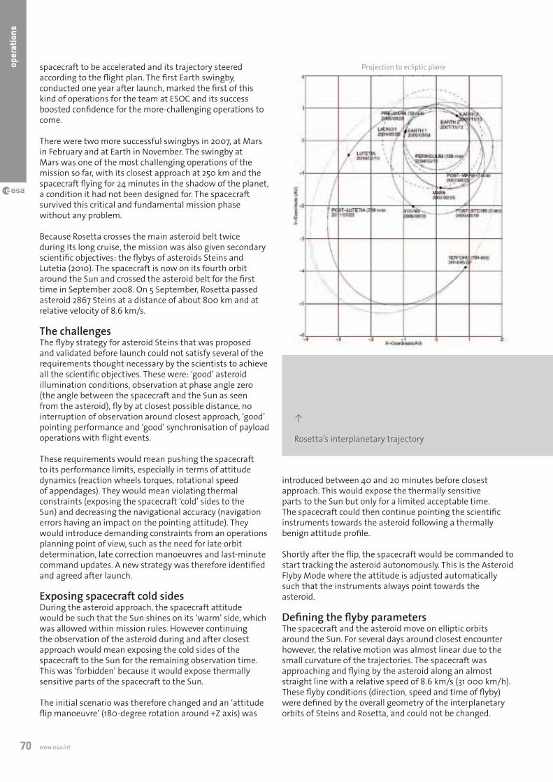
www.esa.int70
oper
atio
ns
spacecraft to be accelerated and its trajectory steered according to the flight plan. The first Earth swingby, conducted one year after launch, marked the first of this kind of operations for the team at ESOC and its success boosted confidence for the more-challenging operations to come.
There were two more successful swingbys in 2007, at Mars in February and at Earth in November. The swingby at Mars was one of the most challenging operations of the mission so far, with its closest approach at 250 km and the spacecraft flying for 24 minutes in the shadow of the planet, a condition it had not been designed for. The spacecraft survived this critical and fundamental mission phase without any problem.
Because Rosetta crosses the main asteroid belt twice during its long cruise, the mission was also given secondary scientific objectives: the flybys of asteroids Steins and Lutetia (2010). The spacecraft is now on its fourth orbit around the Sun and crossed the asteroid belt for the first time in September 2008. On 5 September, Rosetta passed asteroid 2867 Steins at a distance of about 800 km and at relative velocity of 8.6 km/s.
The challengesThe flyby strategy for asteroid Steins that was proposed and validated before launch could not satisfy several of the requirements thought necessary by the scientists to achieve all the scientific objectives. These were: ‘good’ asteroid illumination conditions, observation at phase angle zero (the angle between the spacecraft and the Sun as seen from the asteroid), fly by at closest possible distance, no interruption of observation around closest approach, ‘good’ pointing performance and ‘good’ synchronisation of payload operations with flight events.
These requirements would mean pushing the spacecraft to its performance limits, especially in terms of attitude dynamics (reaction wheels torques, rotational speed of appendages). They would mean violating thermal constraints (exposing the spacecraft ‘cold’ sides to the Sun) and decreasing the navigational accuracy (navigation errors having an impact on the pointing attitude). They would introduce demanding constraints from an operations planning point of view, such as the need for late orbit determination, late correction manoeuvres and last-minute command updates. A new strategy was therefore identified and agreed after launch.
Exposing spacecraft cold sidesDuring the asteroid approach, the spacecraft attitude would be such that the Sun shines on its ‘warm’ side, which was allowed within mission rules. However continuing the observation of the asteroid during and after closest approach would mean exposing the cold sides of the spacecraft to the Sun for the remaining observation time. This was ‘forbidden’ because it would expose thermally sensitive parts of the spacecraft to the Sun.
The initial scenario was therefore changed and an ‘attitude flip manoeuvre’ (180-degree rotation around +Z axis) was
↑
Rosetta’s interplanetary trajectory
Projection to ecliptic plane
introduced between 40 and 20 minutes before closest approach. This would expose the thermally sensitive parts to the Sun but only for a limited acceptable time. The spacecraft could then continue pointing the scientific instruments towards the asteroid following a thermally benign attitude profile.
Shortly after the flip, the spacecraft would be commanded to start tracking the asteroid autonomously. This is the Asteroid Flyby Mode where the attitude is adjusted automatically such that the instruments always point towards the asteroid.
Defining the flyby parametersThe spacecraft and the asteroid move on elliptic orbits around the Sun. For several days around closest encounter however, the relative motion was almost linear due to the small curvature of the trajectories. The spacecraft was approaching and flying by the asteroid along an almost straight line with a relative speed of 8.6 km/s (31 000 km/h). These flyby conditions (direction, speed and time of flyby) were defined by the overall geometry of the interplanetary orbits of Steins and Rosetta, and could not be changed.

71European Space Agency | Bulletin 137 | February 2009
→ ro
sett
a
Only two conditions were adjustable. The first one was the flyby distance (closest approach distance between the spacecraft and the asteroid). For observation purposes, especially for the science cameras on board Rosetta, and to fulfil the scientific requirements, the flyby distance had to be as small as possible. Therefore a distance of 800 km was selected, driven by the maximum rotation speed that the spacecraft could sustain to keep the instruments pointed to the asteroid during the flyby.
The other adjustable characteristic of the flyby was its orientation with respect to the asteroid. To fulfil the requirements, the best choice was to fly by on the dayside of
↙
‘Inverted’ Steins flyby geometry
Sun directi
onDefault pointing Attitude flip Inverted pointing
Z axis
X axis
the asteroid. With this orientation, the phase angle dropped to zero degree at some instance during the approach. At that time, the asteroid appeared fully illuminated by the Sun when observed by a camera on the spacecraft.
Validation of the new scenario An in-flight validation test with the spacecraft was required, in order to prove the robustness and safety of the new scenario. To be as representative as possible, this test had to take place when the angular position of Rosetta relative to Earth and the Sun was the same as the one during the actual Steins flyby. The 24 March 2008 was the only day satisfying these conditions.
The history of our Solar System, its formation and evolution, can be studied by investigating the various Solar System bodies. Asteroids are important because they pre-date the planets and retain a record of that phase of the Solar System’s formation: they are the pieces that got left behind in the process of planet formation.
It is believed that, in the early Solar System, dust accretion in the pre-solar nebula formed the ‘planetesimals’, very early stages of planets consisting of loose groupings of rocks and other matter. These bodies later collided and coalesced, while others
impacted each other with such energy that they fragmented. After millions of years, the coalescence won and several planets were formed.
In the asteroid belt, however, the accretion process was halted with the formation of Jupiter because its enormous gravity shepherded the asteroids into more orderly orbits. This reduced the chances of collision and effectively stopped the asteroids from developing any further into planets.
Asteroids are therefore like a piece of Solar System DNA: they keep a ‘memory’ of the Solar System
formation. Collisions have led to a huge number of asteroids with different compositions and internal structures: all with their own history. It is therefore important to visit and study as many different types of asteroids as possible to understand their evolution.
The flyby of 2867 Steins was the first European asteroid encounter and only the eighth in spaceflight history. Steins is a rare, iron-poor, E-type irregular-shape asteroid with an estimated diameter of 4.6 km and, as such is of much interest to the scientific community.
→ Why fly by asteroids?
253
- Mat
hild
e
243
- Ida
2867
- St
eins
433
- Ero
s
951
- Gas
pra

www.esa.int72
oper
atio
ns
To gain confidence in this validation test, simulations were first performed at the manufacturer premises with the test bed used to validate the Attitude and Orbit Control System (AOCS) during the design phase. The scenario was also run several times with the ESOC software simulator emulating the AOCS software. Both tests were successful and gave the final ‘go’ for the in flight test.
The simulated closest approach time was at 12:00 on 24 March, with the flip manoeuvre taking place between 11:20 and 11:40 and Rosetta entering the spacecraft autonomous tracking mode just after the end of the flip. Some parameters had to be ‘faked’ to allow this special spacecraft mode to work in absence of a real asteroid to track, but from a performance, thermal and dynamic point of view, the test was fully representative.
The timeline of activities was also exactly the same as planned for the real Steins flyby. The whole test took place outside ground station coverage. There was great relief when the New Norcia ground station acquired an X-band signal from Rosetta on 25 March 2008, the first contact with the spacecraft after the test completion! This meant that the spacecraft had gone through all the phases of the test and this was the first indication that everything had worked out nominally.
Rosetta then entered Near Sun Hibernation Mode for several months until early July 2008. This quiet period in spacecraft activities allowed all teams to focus on the Steins flyby phase, perform further validation tests and complete the flyby operations timeline. The ESOC simulator was tested and configured to be able to track a simulated Steins asteroid and enter the autonomous tracking mode. It was also used to rehearse the real flyby timeline, including failure cases to make sure that the real scenario was robust enough.
A few days after Near Sun Hibernation Mode exit, an active payload checkout took place in July 2008. It included payload calibrations, onboard software maintenance and interference testing activities to confirm payload readiness for the Steins flyby. After four weeks of heavy workload on all teams involved, including the Rosetta Science Operations Centre (RSOC) in Spain, all payload teams confirmed their ‘go’ for the flyby activities.
Three simulations in August 2008 made sure all operations teams were properly trained and ready for the critical flyby operations and that, as far as possible, all procedures were in place to react to any spacecraft contingency situation. Rosetta was ready for the start of the flyby phase.
Approach and flybyThe spacecraft orbit is routinely determined throughout the mission using radiometric data (range and Doppler measurements). Similarly, the asteroid had been observed from telescopes around the world over several decades. These observations were used to determine its orbit around the Sun. Based on these independent estimates, it was possible to predict the positions of the spacecraft and the asteroid at the time of closest approach only within a limited accuracy in the order of some 100 km.
The spacecraft had to be guided towards the planned flyby conditions with much better accuracy than that. This was achieved with the combination of traditional radiometric measurements and the use of images of the asteroid taken with the onboard navigation cameras and the OSIRIS science camera.
So the first step of the navigation campaign was to determine the current orbits of the asteroid and the spacecraft more accurately. All three cameras were used to acquire images showing the asteroid together with the surrounding star field. By analysing such images, the direction of Steins relative to the star background could be determined with an accuracy of less than 0.1 millidegree.
→
Steins seen from the first observation slot on 4 August (Steins marked, with a magnitude of about 12 at that time, i.e. fainter than the detection limit of the navigation camera). The bright star at upper left is Iota Virginis of the constellation Virgo with magnitude 4. This is the brightest object in the field of view. The extended white spots are stars. Almost all other small white spots are artefacts from the CCD sensor (pixel dark current).

73European Space Agency | Bulletin 137 | February 2009
→ ro
sett
a
These measurements allowed estimating the relative direction of the target with increasing accuracy (the angular error of 0.1 millidegree is equivalent to a smaller position error when the distance to the target becomes shorter). It was the first time this technique was applied to navigate a European spacecraft.
The subsequent steps of the navigation campaign were carried out only if an orbit correction turned out to be necessary. They consisted in determining an optimal trajectory correction manoeuvre to adjust the orbit in order to meet the flyby conditions.
Planning processThe planning process was one of the most complicated in the mission so far. It had to be defined in an incremental way, accommodating the flyby navigation strategy and link of some commanding products to the results of previous planning activities.
The four weeks before the flyby included 13 optical navigation slots, two trajectory correction manoeuvre slots and the first payload activities. The flyby week was by far the most complicated from a planning point of view, with the final four navigation slots and final three manoeuvre slots. The high accuracy achieved in the navigation and the excellent performance of the spacecraft meant the ground team only needed two of the planned manoeuvre slots, for small corrections of the spacecraft trajectory.
The final critical ‘go’/‘no go’ decision for entering the spacecraft autonomous tracking mode was to be taken between seven and two hours before closest approach, because the navigation cameras would not be able to track the asteroid before. All activities had also to take into account the 20 minutes signal travel time between Earth and the spacecraft, which did not allow for any immediate reaction from ground to any unexpected event or malfunction.
Payload activities and expected scientific outputAll but three Rosetta payload instruments were operated during the Steins flyby. They covered: imaging and
spectroscopy, magnetic and radiation environment monitoring of Steins, search for gas and dust particles around the asteroid, as well as radio science.
The scientists expected to be able to derive the accurate size, shape, volume, rotation rate and albedo of the asteroid. They would be able to perform multi-colour imaging of its surface and multi-wavelength spectral mapping, determine its surface morphology, composition and density, analyse its environment in a search for satellites and detect potential gas release, as well as study the interaction of the asteroid with the space environment.
←
Narrow angle (left) and wide angle (far left) camera composites of Steins
First scientific resultsSteins was measured at 5.9 x 4.0 km. The first preliminary results showed that the asteroid is dominated by a large crater on the northern part as well as an interesting chain of craters. The impact that created the large crater was most probably so immense it could have almost broken apart the asteroid. With craters of different ages and a ‘regolith’ cover inferred from degraded craters, Steins must have experienced a complex collisional history. The Rosetta instrument teams are currently analysing the huge amount
closest approach was 802.6 km, occurring only four seconds later than the time estimated for planning purposes.

www.esa.int74
oper
atio
ns
and occurred at 18:38:20.1 UTC, only five seconds later than the final prediction and four seconds later than the targeted time estimated in mid August for payload planning purposes. Rosetta flew slightly south of the Steins-to-Sun direction such that the minimum phase angle was just 0.27 degrees and occurred 117 seconds before closest approach.
Without the benefit of optical navigation, the desired closest approach distance would have been missed by more than 100 km.
Rosetta now continues its long journey towards the comet. The spacecraft has never before been so far away from Earth and the Sun. A last swing-by at Earth in November 2009 will boost the spacecraft on its final target orbit to approach the comet in 2014.
of science data generated and the results will be published in the coming months.
Navigation camera trackingTwelve hours before the flyby, the navigation camera was commanded to track the asteroid for the first time. In this mode, the camera should autonomously detect the asteroid and determine periodically its position in the field of view. These measurements are used by the attitude control system of the spacecraft in its autonomous tracking mode during the flyby. According to the mission rules, successful camera tracking was a condition that had to be fulfilled for the ‘go’ for entering autonomous tracking mode.
In case of ‘no go’, the spacecraft would follow a back-up attitude profile predetermined on the ground, based on the best knowledge of the flyby trajectory. Due to the high speed of the flyby, and the high uncertainty in the time, which could not be reduced by optical measurements, it was likely that the instruments would not point accurately enough at Steins if this back-up profile was followed.
When the first telemetry arrived from the camera in tracking mode, it became clear that the unit was not performing as
the asteroid just in time for the ‘go’/‘no go’ decision for autonomous tracking mode.
Thanks to the successful near real-time operational support, it was possible to achieve the objectives set for the conditions of the scientific observations. It turned out only after full attitude and orbit reconstruction that the optimum pointing performance had not been fully met throughout the tracking period. Data analysis is ongoing to support the preparation of the Lutetia asteroid flyby in July 2010, to achieve the best possible performance.
Navigation resultsOne day before the flyby, based on all the optical navigation data, including 340 measurements of the direction of Steins seen from Rosetta, it was expected that the closest approach distance would be 800.4 km and occur at 18:38:15 UTC on 5 September. The uncertainty on the flyby time was twelve seconds, equivalent to 105 km along the relative trajectory, and so quite high.
After the flyby, the processing of OSIRIS camera images contributed to provide very precise, final navigation results. The distance to Steins at closest approach was 802.6 km
expected. After careful check-out of telemetry, including images that were commanded to support the analysis, it was concluded that the malfunction was due to a special combination of effects which comprised the presence of ‘warm’ pixels on the CCD (pixels that generated a significant signal without optical stimulation), the software algorithm of the camera for processing the CCD output and the apparent size of the target, which was still smaller than the size of a single pixel. It was also concluded, that these conditions would not improve sufficiently in time for the ‘go’/‘no go’ decision.
Several other camera settings with the redundant camera unit were discussed and tested: modification of the optical filter, disabling of automatic exposure control and modification of the tracking window size. With only two hours to go to the flyby, a setting was found in which both cameras (nominal and redundant) could successfully track
←
A scene of celebration in the Rosetta mission control room at ESOC after the flyby

Together, we take you farther.
ExcEllEncE in qualiTy – for your safETy and sEcuriTy
RUAG Aerospace develops, manufactures and tests components,
structures, instruments and equipment for satellites and launch
vehicles. Now we have joined forces with Saab Space and Austrian
Aerospace. Your contacts are still the same highly skilled partners
you are used to. Our aim in joining our forces into one single vig-
orous and highly productive company is, of course, to strengthen
our innovativeness. In this regard we plan on becoming even better
than before.
RUAG Aerospace Ltd.P.O. Box 3016032 Emmen · SwitzerlandTel. +41 412 684 311Fax +41 412 683 948
RUAG Aerospace Sweden AB405 15 GöteborgSwedenTel. +46 (0) 31 735 00 00Fax +46 (0) 31 735 40 00
RUAG Aerospace Austria GmbHStachegasse 161120 Vienna · AustriaTel. +43 (0) 1 80199 0Fax +43 (0) 1 80199 6950
[email protected] · www.ruag.com
RZ Ins_Space_RUAG_A4_e.indd 1 9.12.2008 15:40:10 Uhr

→ nEWS
in brief

→ nEWS
A NASA/ESA Hubble Space Telescope image of a pair of massive stars, WR 25 (centre) and Tr16-244, embedded within the Carina Nebula, an immense cauldron of gas and dust about 7500 light-years from Earth. The second brightest star, to the left of WR 25, is not part of this cluster and is located much closer to Earth than the Carina Nebula.

new
s
78 www.esa.int
Space ministers agree on the role of space for EuropeThe Ministers in charge of space activities in ESA’s 18 Member States and Canada concluded a two-day Council meeting in The Hague last November, agreeing to undertake new initiatives and endorsing the next phases of ESA’s programmes.
The decisions made were a further step towards giving Europe the means to respond to global challenges. In keeping with the European Space Policy, designed in cooperation with the European Commission, the measures will further strengthen Europe’s role in the development and exploitation of space applications serving public policy objectives and the needs of European citizens and enterprises.
These decisions have particular relevance at the present time, showing as they do Europe’s determination to invest in space as a key sector providing for innovation, economic growth,
strategic independence and the preparation of the future.The Ministers also adopted four Resolutions on the role of space in delivering Europe’s global objectives, the Level of Resources for ESA to cater for Space Science programmes and basic activities in the period 2009‒13, the renewal of the contribution of ESA Member States to the running costs of Europe’s spaceport in French Guiana; and the future evolution of ESA, spanning its financial management reform, decision-making processes, industrial and procurement policies and the further development of site infrastructures for ESA programmes.
On the programmatic side, the Ministers took decisions concerning the full range of ESA’s mandatory and optional programmes. In particular, in Earth observation activities, the second segment of the Global Monitoring
for Environment and Security Space Component programme, Meteosat Third Generation development and a novel Climate Change Initiative to provide essential climate variables, were approved.
In human spaceflight, programmes for the exploitation and evolution of the International Space Station will continue, and definition studies will begin on the evolution of a returnable transfer vehicle.
In telecommunications, preparatory work for a European Data Relay System (EDRS), an air traffic management satellite system (Iris) and Integrated Application Promotion combining usage of telecommunications, Earth observation and navigation satellite systems with terrestrial information and communications systems, will begin.
A Space Situational Awareness programme will be formed to provide the information to help protect European space systems against space debris and the influence of adverse space weather.

↑
The Netherlands, as seen from ESA’s Envisat satellite, with Amsterdam visible in white on the south bank of the North Sea Canal (extending in an east-west direction above image centre).
The port of Rotterdam is in the bottom left corner, and The Hague, the country’s third largest city, is visible on the coast above the port of Rotterdam. The Hague hosted ESA’s Ministerial Council in November 2008, setting out the start of ESA’s future programmes and taking decisions on the next phases of on-going programmes.
On the coast between The Hague and the North Sea Canal, is the town of Noordwijk, home to ESA’s European Space Technology Research Centre (ESTEC). ESTEC is the largest site of ESA, where more than 2000 specialists work on dozens of space projects, guiding them through the various phases of development.
Rotterdam (inland from the port) is the country’s second largest city after Amsterdam. The city centre is situated on the northern bank of the New Meuse River, which divides the municipality into its northern and southern parts. The Netherlands’ fourth largest city, Utrecht, is seen in white to the right of centre.

new
s
80 www.esa.int
Your pictures in spaceThree winners have been chosen of the competition for children ages 6–12 to design a T-shirt for ESA astronaut Frank De Winne to wear in space.
Within just a few weeks of launching the competition, over 2000 drawings were received from primary school children eager to see Frank De Winne wearing their t-shirt during his mission to the ISS this year. The winners are: Alexandra Angellotti (12), from Italy, Bruno Tedim Guerra (11),
from Portugal, and ImanBouwens (8), from Belgium.
During his six-month mission in space, De Winne will teach lessonsvia radio links to children on Earth, when he will wear the T-shirts with the designs by the winners.
Together with their classmates, Alexandra, Bruno and Iman will be able to talk to Frank De Winne in space, when he will personally congratulate them.
←
chandrayaan-1 starts observations of the moonThe European SIR-2 near-infrared spectrometer on board the Indian Space Research Organisation’s Chandrayaan-1 lunar orbiter was commissioned on 19 November. The instrument sent back housekeeping data indicating normal operation and science observations began on 20 November.
A few days earlier, Chandrayaan-1 had released a probe that impacted close to the lunar south pole on 14 November. The Moon Impact Probe was dropped close to Shackleton crater, where ice may exist in areas that are never illuminated by the Sun. It carried three instruments: a video imaging system, a radar altimeter and a mass spectrometer.
The imaging system took pictures of the Moon as it approached the surface, the radar was used to determine the altitude and the mass spectrometer was used to study the thin lunar atmosphere. The probe was released from the spacecraft at 15:36 CET on 14 November and took 25 minutes to reach the surface. As it descended, the probe
transmitted pictures to the orbiter that were later downloaded to Earth.
The orbiter’s Terrain Mapping Camera and the Radiation Dose Monitor
were also functioning by that time and, after the impact of the probe, the remaining orbiter instruments including SIR-2 were switched on for their commissioning activities.
↑
The lunar polar region taken by Chandrayaan-1’s Terrain Mapping Camera on 15 November 2008 (ISRO)
↑
By Alexandra Angellotti

→ ne
ws
81European Space Agency | Bulletin 137 | February 2009
←
European mars500 participants selectedFour Europeans have been selected to take part in a 105-day simulated mission to Mars. From March next year, two of the group will join four Russian participants inside an isolation facility in Moscow to experience elements of a simulated Mars mission.
The purpose of the Mars500 study is to gather data, knowledge and experience to help prepare for a possible real mission to Mars. The participants will act as subjects in scientific investigations to assess the effect that isolation has on various psychological and physiological aspects, such as stress, hormone regulation and immunity, sleep quality, mood and the effectiveness of dietary supplements.
Chosen from 5600 initial applicants, the four will complete a two-month period of training for their mission, then two of the group will be chosen as prime crew to join four Russian-selected crewmembers inside the specially designed facility in Moscow. The other two will act as back-up crew.
For 105 days, as part of a cooperative project between ESA and the Russian
Institute for Biomedical Problems (IBMP), the six-strong crew will live, eat, sleep and work in the recently refurbished facility. The crew of six is set to enter the isolation facility on 24 March 2009. Their stay is in preparation for the full Mars500 study due to start later in 2009, which will see another six-member crew sealed in the chamber to experience a complete 520-day Mars mission.
The four participants are Cedric Mabilotte (34), from Paris, airline
pilot Cyrille Fournier (40), also from Paris, electrical engineer Arc’hanmael Gaillard (32), from Rennes, France, and army engineer Oliver Knickel (28), from Hamburg, Germany.
↑
From left: Cedric Mabilotte, Oliver Knickel, Cyrille Fournier, Arc’hanmael Gaillard.
↑
By Bruno Tedim Guerra
↑
By Iman Bouwens

new
s
82 www.esa.int
new
s
www.esa.intwww.esa.int
hubble finds carbon dioxide on extrasolar planetThe NASA/ESA Hubble Space Telescope has discovered carbon dioxide in the atmosphere of a planet orbiting another star. This is another important step in finding the chemical ‘biotracers’ of life as we know it on other worlds. The Jupiter-sized planet, called HD 189733b, is too hot for life but new Hubble observations prove that the basic chemistry for life can be measured on planets orbiting other stars. Organic compounds can also be by-products of life processes and their detection on an Earth-like planet may someday provide the first evidence for life beyond Earth.
Previous observations of HD 189733b by Hubble and the Spitzer Space Telescope found water vapour. Earlier this year Hubble found methane in the planet’s atmosphere. However the carbon dioxide is the focus of the excitement, because that is a molecule that under the right circumstances could have a connection to biological activity, as it does on Earth.
An international team of astronomers used Hubble’s Near Infrared Camera and Multi-Object Spectrometer (NICMOS) to study infrared light emitted from the planet, which lies 63 light-years away. Gases in the planet’s atmosphere absorb certain
wavelengths of light from the planet’s hot glowing interior. The team identified not only carbon dioxide, but also carbon monoxide. The molecules leave their own unique spectral fingerprint on the radiation from the planet that reaches Earth.
This is the first time a near-infrared emission spectrum has been obtained
for an extrasolar planet. This successful demonstration of looking at near-infrared light emitted from a planet is very encouraging for astronomers planning to use the NASA/ESA/CSA James Webb Space Telescope when it is launched in 2013. Biomarker molecules are best seen at near-infrared wavelengths.
↑
Artist’s impression of the Jupiter-size extrasolar planet, HD 189733b, being eclipsed by its parent star (ESA/NASA/M. Kornmesser and STScl).
ESA launched its own YouTube site in a new initiative to communicate even more widely with the general public by using the latest social media channels. Officially launched on 7 November, the ESA YouTube channel is part of a new communications strategy that will give a more ‘human’ face to the work
Bringing space to youdone at ESA. The growing popularity of internet-based social media and networking channels, such as YouTube, is enabling ESA to reach important new target audiences and engage the public using ESA productions in novel ways.
One of the themes of ESA’s latest channel is that space development is driven forward by people, whether
scientists and engineers at ESA, space workers in European industry, students with a passion for space, or the curious general public. There will be music clips, videos produced for exhibitions and other items that provide a general overview of ESA and capture the excitement of space. See www.youtube.com/esa

→ hEAding for ThE iSS

ESA astronaut Frank De Winne (B) is set to become the first European Commander of the International Space Station. De Winne, will fly to the ISS in a Soyuz spacecraft in May 2009 with cosmonaut Roman Romanenko and Canadian Space Agency astronaut Robert Thirsk.
For the first four months, De Winne will be Flight Engineer on Expedition 20. With a crew rotation due in October, De Winne become Commander of Expedition 21 until his return to Earth in November 2009. His back-up is ESA astronaut André Kuipers (NL).
The next European long-term mission has also been confirmed. Paolo Nespoli (I) will be Flight Engineer on Expeditions 26 and 27. His launch is due in November 2010, returning to Earth six months later in May 2011.
ESA photographer Stephane Corvaja caught up with all five astronauts recently during training at Star City near Moscow.
↑
De Winne learning how to dock Soyuz with the ISS manually using laser distance-measuring equipment
↓
André Kuipers leaves the Soyuz simulator
↓
Soyuz TMA-15 Commander Roman Romanenko oversees the training
84 www.esa.int

↓
André Kuipers leaves the Soyuz simulator
↑
Canadian Bob Thirsk gives a thumbs-up!
↓
Paolo Nespoli in the Soyuz simulator
85European Space Agency | Bulletin 137 | February 2009

→ ProgrAmmES in ProgrESS
status at end december 2008


2005 2006 2007 2008 2009 2010 2011 2012 COMMENTS
DEFINITION PHASE MAIN DEVELOPMENT PHASE OPERATIONS STORAGE
ADDITIONAL LIFE POSSIBLE
LAUNCH/READY FOR LAUNCH
ASTRONAUT FLIGHT
HUBBLE
ULYSSES
SOHO
XMM-NEWTON
CLUSTER
INTEGRAL
MARS EXPRESS
SMART-1
DOUBLE STAR
ROSETTA
VENUS EXPRESS
HERSCHEL/PLANCK
LISA PATHFINDER
MICROSCOPE
GAIA
JWST
EXOMARS
BEPICOLOMBO
SOLAR ORBITER
LISA
LAUNCHED APRIL 1990
LAUNCHED OCTOBER 1990
LAUNCHED DEC 1995 / OPS EXTENDED UNTIL 31 DEC 2009
LAUNCHED DEC 1999 / OPS EXTENDED UNTIL 31 DEC 2012
LAUNCHED MID-2000
LAUNCHED OCTOBER 2002
LAUNCHED JUNE 2003
LAUNCHED SEPTEMBER 2003, IMPACTED MOON 2006
TC-1 LAUNCHED DEC 2003 / TC-2 LAUNCHED JULY 2004
LAUNCHED MARCH 2004
LAUNCHED NOVEMBER 2005
LAUNCH 16 APRIL 2009
LAUNCH EARLY 2011
LAUNCH EARLY 2011
LAUNCH DECEMBER 2011
LAUNCH JUNE 2013
LAUNCH 2016
LAUNCH AUGUST 2014
LAUNCH JANUARY 2017
LAUNCH END 2017
SCIE
NCE
& R
OBOT
IC E
XPLO
RATI
ONPR
OGRA
MM
E
METEOSAT-5/6/7
ERS-2
ENVISAT
MSG
MTG
METOP
CRYOSAT
GOCE
SMOS
ADM-AEOLUS
SWARM
EARTHCARE
SENTINEL-1
SENTINEL-2
SENTINEL-3
M5 LAUNCHED 1991, M6 1993, M7 1997
LAUNCHED APRIL 1995 / OPS EXTENDED TO MID-2011
LAUNCHED MARCH 2002 / POSSIBLE EXTENSION BEYOND 2010
MSG-3 LAUNCH 2011, MSG-4 LAUNCH 2013
LAUNCH MTG-I-1 END 2015 / MTG-S-1 2017
METOP-A LAUNCH OCT 2006 / METOP-B 2011 / METOP-C 2013
LAUNCH FAILURE OCT 2005 / CRYOSAT-2 LAUNCH NOV 2009
LAUNCH 16 MARCH 2009
LAUNCH JULY 2009
LAUNCH APRIL 2011
LAUNCH 2010
LAUNCH MID-2013
LAUNCH NOVEMBER 2011
LAUNCH OCTOBER 2012
LAUNCH NOVEMBER 2012
ARTEMIS
ALPHABUS
ALPHASAT
SMALL GEO SAT.
GNSS-1/EGNOS
GALILEO
PROBA-1
PROBA-2
COLUMBUS
ATV
NODE-2 / -3 / CUPOLA
ERA
ISS BARTER / UT. PR.
EMIR/ELIPS
MFC
ASTRONAUT FLT.
AURORA CORE
ARIANE-5
VEGA
SOYUZ AT CSG
LAUNCHED JULY 2001, OPERATIONS EXTENDED
LAUNCH JUNE 2012
LAUNCH MID 2012
OPERATIONS START 2008
GIOVE-A LAUNCHED DEC 2005 / GIOVE-B APRIL 2008 / IOV 2009-10
LAUNCHED OCTOBER 2001
LAUNCH JULY 2009
OPERATIONAL
FIRST LAUNCH NOVEMBER 2009
FIRST LAUNCH MID-2009
MEL
FI -1
FOTO
N-M
3
MAS
ER-1
1
TEXU
S-44
MAX
US-8
TEXU
S-46
MAR
ES
TEXU
S-45
MEL
FI-2
HUM
AN S
PACE
FLIG
HT
PROG
RAM
ME
LAUN
CHER
PR
OG.
TECH
.PR
OG.
TELE
COM
MS/
NAV
.PR
OGRA
MM
ESEA
RTH
OBS
ERVA
TION
PROG
RAM
ME
LAUNCHED FEBRUARY 2008
FIRST LAUNCH MARCH 2008, ATV-2 MID-2010, ATV-3 MID-2011
LAUNCH: NODE-2 OCT 2007 / CUPOLA WITH NODE-3 FEB 2010
LAUNCH NOT BEFORE END-2009
EDR / EUTEF / SOLAR WITH COLUMBUS
BIOLAB, FSL, EPM WITH COLUMBUS
DE WINNE:MAY-NOV 2009, FUGLESANG:JUL-AUG 2009, NESPOLI:NOV 2010
TEXUS 44/45:FEB. 2008,TEXUS 46:MAY 2009,MAXUS 8:NOV.2009,MASER 11:MAY 2008

prog
ram
mes
90 www.esa.int
prog
ram
mes
→ hUBBLE SPAcE TELEScoPE
The NASA/ESA Hubble Space Telescope is back in business. Science operations were resumed on 25 October 2008, four weeks after a problem with the science data formatter took the spacecraft into a ‘safe mode’. Just a couple of days after Hubble was brought back online, it photographed an intriguing target: a pair of gravitationally interacting galaxies called Arp 147 in the constellation of Cetus, more than 400 million light-years from Earth.
Then it was announced in November that Hubble had taken the first visible-light image of a planet circling another star. Estimated to be no more than three times Jupiter’s mass, the planet Fomalhaut b orbits the bright southern star Fomalhaut, located 25 light-years away in the constellation Piscis Australis.
Fomalhaut has been a candidate for planet-hunting ever since an excess of dust was discovered around the star in the early 1980s by the US-UK-Dutch IRAS satellite. In 2004, Hubble confirmed that a large dust belt surrounded the star and astronomers later proposed that dust ring is being ‘gravitationally modified’ by a planet between the star and the ring’s inner edge.
This image of galaxy pair Arp 147 was taken on 27‒28 October 2008 by the Hubble Space Telescope (NASA/ESA/M. Livio, STScI)
The newly discovered planet, Fomalhaut b, taken with the Hubble Advanced Camera for Surveys. Inset, the planet’s position during observations made in 2004 and 2006. The white dot in the centre marks the star's location, and the surrounding region is black because the Advanced Camera’s coronagraph was used to block out the star’s bright glare so that the dim planet could be seen (NASA/ESA/P. Kalas, Univ. of California, Berkeley)

91European Space Agency | Bulletin 137 | February 2009
→ in
pro
gres
s
More Hubble images showed that an object was moving along a path around the star and was therefore gravitationally bound to it. Fomalhaut b was confirmed as a real astrophysical object. Now, Hubble has photographed the planet as a point source of light lying over 2 billion km inside the ring’s inner edge.
The planet is about 15 billion km from the star, or about 10 times the distance of the planet Saturn from our Sun. The planet’s upper-mass limit is constrained by the appearance of the Fomalhaut ring. If the planet were much more massive, it would distort the ring, and the effect would be observable in the ring’s structure. Astronomers have calculated that Fomalhaut b completes an orbit around its parent star every 872 years.
The planet is brighter than expected for an object of three Jupiter masses. One possibility is that it has a huge Saturn-like ring of ice and dust reflecting starlight. The ring might eventually coalesce to form moons. The ring’s estimated size is comparable to the region around Jupiter that is filled with the orbits of the four largest satellites.
→ ULYSSES
Ulysses continues to return useful science data at the time of writing, indicating that the adopted strategy of ‘fuel bleeding’, described in the last Bulletin, is still effective in preventing freezing of the remaining hydrazine. The Ulysses Science Working Team met for the 60th and last time in mid-November. Although the spacecraft is still operational, it was decided that this would be the final official SWT meeting given the imminent end of the mission.
The unexpected longevity of the spacecraft is making it possible to obtain unique, high-latitude data to help characterise the solar wind during the present solar minimum, which is unusually long. Even though the Sun remains largely quiescent, the inclination of its magnetic equator with respect to the rotational equator is currently larger than normally observed at solar minimum. This in turn is allowing Ulysses, which was located at 32° North solar latitude on 1 January, to investigate in detail the boundary between ‘fast wind’ from the northern pole and ‘slower wind’ from the region around the Sun’s magnetic equator.
→ cASSini/hUYgEnS
After concentrating on Enceladus in 2008, Cassini is focusing on Titan for a while, although additional low-altitude Enceladus flybys, directly through the plumes ejected from its south pole, are planned during the latter part of the Cassini Equinox Mission. In November 2008, the Visual Infrared Mapping Spectrometer instrument, using a special imaging
mode, obtained the highest possible resolution images (about 1 km) near and around the Huygens landing site. This may help to shed new light on the odd rotation state of Titan's icy crust discovered by the radar observations. In late December, the first altimetry profile over a lake was obtained by radar over ‘Lake Ontario’, the southern lake containing ethane liquid that was identified in early 2008 using infrared spectroscopy.
→ Xmm-nEWTon
On 18 October 2008 ESA lost contact with XMM-Newton while it was approaching perigee passage and communicating normally with the Santiago ground station in Chile. After several unsuccessful attempts to recover the spacecraft, the problem was still present even when other ESA ground stations were used. This confirmed that the loss of contact was related to either an onboard problem or a catastrophic event in orbit. On 20 October images of the track of XMM-Newton against the night sky, taken by amateur astronomers from Germany’s Starkenburg observatory, showed that the satellite was still in one piece.
On 21 October the more powerful ESA 35 m ground station at New Norcia (Western Australia) was pointed in the direction of XMM-Newton using a special radio-science mode. A weak signal was detected from the spacecraft, helping confirm suspicions that the antenna switch was stuck in an intermediate position. A spacecraft emergency was declared
Artist impression of the planet orbiting Fomalhaut (ESA/NASA/L. Calcada, ESO for STScI)

prog
ram
mes
92 www.esa.int
Star forming in the Small Magellanic Cloud (D.A. Gouliermis)
and support requested from NASA’s Deep Space Network Goldstone antenna. Owing to its location, Goldstone provides visibility of the spacecraft when it is very close to Earth, allowing a higher signal power at the spacecraft. Commands were sent to move the antenna switch back to its last working position and, finally, full radio contact with the spacecraft was re-established using the 15 m ground station at Villafranca on 22 October. Following the recovery, it was confirmed that there had been no degradation of any of the instruments while the spacecraft was out of communications.
A multi-wavelength study of NGC 346 combining X-ray, infrared and visible light captured by XMM-Newton, Spitzer and the ESO’s New Technology Telescope has been carried out. NGC 346/N66 is a star-forming region in the Small Magellanic Cloud. Evidence for at least two different events of triggered star formation was found. An arc-like nebular feature, north of the central bright OB stellar association, is characterised by a high concentration of emission-line stars and young stellar objects, as well as embedded sources seen as infrared emission peaks that coincide with young compact clusters of low-mass pre-main-sequence stars. All these objects indicate that the northern arc of N66 encompasses the most current star formation event in the region. This evidence suggests that this star formation is the product of a different mechanism than that in the general area of the association, triggered by a wind-driven expanding H II region (or bubble) blown by a massive supernova a few million years ago.
→ cLUSTEr
Cluster constellation phasing and attitude manoeuvres were performed in November 2008 to form a 10 000 km tetrahedron in the solar wind. Starting in mid-April, the configuration will be changed to have the spacecraft close together in the auroral zone.
The flight control and science operations teams have started to prepare the short eclipse season. The season will be the longest experienced by Cluster with four eclipses (one on each spacecraft) every 2.5 days from 25 February 2009 up to 15 May 2009. Cluster 2 will have enough battery power to keep the payload switched on. Cluster 4 will have to switch off its payload during the eclipses, and Clusters 1 and 3, being in decoder-only mode, will switch their payloads off and on a few hours before and after the eclipses.
Cluster results were published reporting a new estimation of the amount of plasma leaving the Earth ionosphere, called ‘ionospheric outflows’, using electric field instruments. The method used is based on ‘perturbations’ of the electric field probes by ion outflows that create a wake near the spacecraft and give a spurious electric field. This spurious electric field can be used to estimate the ion outflow, at around 1026 /s.
→ doUBLE STAr
Contact with Double Star TC2 could not be re-established in November or December. The Chinese operations teams are investigating what could be the problem and are regularly trying to contact the spacecraft. EPOS (RAL), who operate the two European instruments (PEACE and FGM) will continue to prepare commands until end January and then will wait a recovery of the spacecraft before restarting operations after the next eclipse season.
→ inTEgrAL
Integral operations continue smoothly with the spacecraft, instruments and ground segment all performing nominally.
The global properties of all gamma-ray bursts (GRBs) detected by Integral have been determined, and the rate over the whole sky is about 1400 per year above the trigger threshold of the IBIS hard X-ray/soft gamma-ray telescope on board. Many GRBs exhibit a ‘spectral lag’, i.e. a time delay between the arrival of the high-energy (50–300 keV) and low-energy (25–50 keV) photons. The spectral lag was measured for 28 Integral GRBs and two groups were identified in the lag distribution, one with short lags (< 0.75 s) and the other with longer lags. The long-lag GRBs all have low peak fluxes – close to the IBIS sensitivity limit – and have faint optical and X-ray afterglows. They are observed preferentially from the direction of the ‘supergalactic’ plane, tracing nearby clusters of galaxies and the local large-scale structure of the Universe.

93European Space Agency | Bulletin 137 | February 2009
→ in
pro
gres
s
The rate of the low luminosity GRBs is estimated to be about 25% of all events related to core collapse supernovae of Type Ibc. If they are indeed intrinsically under-luminous local events, they could vastly outnumber classical GRBs.
→ mArS EXPrESS
Following a late discovery of a potentially dangerous Phobos flyby in late December 2008, a strategy was implemented to change the flyby into a safe one. From the end of November to mid-December, the spacecraft went through solar conjunction and, except for a number of radio science measurements to study the solar corona, no further scientific observations were possible. The spacecraft exited from solar conjunction on 21 December 2008.
The molecular oxygen abundance is now measured in the atmosphere by the SPICAM spectrometer using the stellar occultation technique, at the altitude range 60–120 km. The previous (and only) measurements in the upper atmosphere were performed by the Viking landers during their descent to the surface in 1976, providing a molecular oxygen profile from 180 km down to 130 km height. The SPICAM data analysis enables the study of the seasonal variations of oxygen in the martian atmosphere.
Data and images suggest that several 'Light Toned Deposits', some of the least understood features on Mars, were formed when large amounts of groundwater burst onto the surface. Scientists propose that groundwater had a greater role in shaping the martian surface than previously believed, and may have sheltered primitive lifeforms as the planet started drying up.
→ roSETTA
After the successful flyby of asteroid 2867 Steins, the detailed data evaluation is taking place. The first results were already reported at various conferences, confirming that an excellent scientific outcome has been achieved. The surface temperature of the asteroid was found by VIRTIS to vary between –90°C and –240°C. Steins was predicted to be a member of the rare highly evolved E-type asteroids, an assumption that was fully confirmed by the images and spectra taken at optical and infrared wavelengths.
The Rosetta flyby was the first (and might remain the only) spacecraft encounter with this rare type of asteroid. Ground-based observers had determined that the surface of such asteroids might contain large amounts of enstatite, a mineral that is produced only by very high temperatures and
Iani Chaos on Mars, an area where Light Toned Deposits are known to be present. This image was obtained with the High Resolution Stereo Camera on ESA’s Mars Express (ESA/DLR/FU Berlin/G. Neukum)

prog
ram
mes
94 www.esa.int
melting, indicating that Steins must have been a part of a much bigger differentiated body. Images taken by the OSIRIS camera through different colour filters make it possible to see how the composition may vary on the surface and provide clues to the history and evolution of the surface of this ancient body.
Directly after the Steins flyby, stereo observations of gravitational microlensing events were obtained by observing in parallel with OSIRIS and telescopes on Earth. Seven slots were allotted to these measurements and about 50 images were obtained near the galactic centre. Events were detected and compared to ground-based observations. The analysis is still under way. The spacecraft has spent 10 weeks in the active cruise phase, first dedicated to the downlink of remaining scientific data from the asteroid phase and then executing remaining payload checkouts (PC8) and investigations linked to anomalies recorded during the flyby phase.
On 17 December 2008, Rosetta entered the conjunction phase, for which the angular separation between Earth and the Sun as seen from the spacecraft will stay below 3° (conjunction) until 6 January 2009 with the minimum (1.65°) on the 27 December 2008. No special activities were planned for this conjunction phase.
→ VEnUS EXPrESS
Venus Express has now sent back more data than any other spacecraft that has orbited Venus (excluding the Magellan mission with its inherently high-rate raw radar data). The data processing is now largely automated and the science teams are focusing on higher level data analysis and interpretation of the results. Several investigations are using data from two or more instruments and a number of such joint studies have recently resulted in publications in leading journals. The Venus Express science archive is being filled with more data for use by the scientific community.
Results published in Nature, combining data collected with the VMC and the VIRTIS instruments, address the atmospheric conditions that give rise to the presence and distribution of the as-yet-unidentified UV absorbers. These absorbers are responsible for the characteristic dark features in the UV images of Venus’s cloud deck. It is mainly the temperature and atmospheric dynamics that drive the global pattern of the UV markings. These also determine the variations of the cloud top altitudes over the Venus globe.
Venus Express will feature in a 50-minute programme, part of the Discovery Channel’s series ‘The Naked Scientist’, in the second quarter of 2009.
→ AKAri
Akari continues routine operations in its post-helium phase. Open Time observations started on 15 October 2008 and 142 European observations have been executed so far.
The first All-Sky Survey catalogue was released internally to the project teams. It contains 64 000 bright sources detected in the far infrared bands (65, 90, 140 and 160 micron) with good quality in the 90 micron band. The public release is planned for Autumn 2009. The second special issue of the Publication of the Astronomical Society of Japan dedicated to Akari, containing 13 papers, was published in December 2008.
→ hinodE
The Hinode team has published observations of the magnetic landscape of the polar region of the Sun that are unprecedented in terms of spatial resolution, field of view and polarimetric precision. They found many vertically oriented magnetic flux tubes with kGauss field strength at latitudes between 70° and 90°. All flux elements have the same polarity, consistent with the global magnetic field structure of the polar region. The field vectors are observed to diverge from the centres of the flux elements, consistent with a view of magnetic fields that are expanding and fanning out with height. The polar region is also found to have ubiquitous horizontal fields. The scientists suggest that the flux tubes serve as efficient ‘chimneys’ for Alfvén waves that accelerate the solar wind.
→ coroT
COROT continues to operate normally. The rate at which planet candidates are confirmed by follow-up observations has increased to about one planet every four weeks. The number of candidates is however increasing faster and the total is several hundreds. The confirmation process takes anything from several months to over one year, depending on a combination of factors, ranging from celestial mechanics to the access to and schedule of ground-based telescopes. The situation should improve thanks to the recent allocation of up to 60 nights of observations on the Keck telescopes through collaboration with the University of Texas. The first Keck observation is scheduled on 7 January 2009.
Up to now, four COROT exoplanet detections have been published, and articles are in preparation for two additional planets. A further six exoplanets are in the final stages of confirmation and analysis. The most interesting object being followed up at the moment shows an eclipse depth of 0.0003. Pending final confirmation, this is probably a multi-planet system involving a low-mass terrestrial planet.

95European Space Agency | Bulletin 137 | February 2009
→ in
pro
gres
s
→ hErSchEL/PLAncK
The test activities on both spacecraft are coming to an end in January 2009 and the shipment to the launch site is scheduled for mid-February.
The highlight for the Herschel spacecraft of the last quarter of 2008 was the conduct of the Thermal Balance and Thermal Vacuum (TB/TV) test of the fully integrated spacecraft in the Large Space Simulation (LSS) facility at ESTEC. This test
followed a launch simulation in which Herschel helium cryostat was filled, and the launch transient behaviour of the complete cryo-system was demonstrated. The cryostat temperature evolution as measured during the test followed the prediction very closely, clearing this major performance verification aspect.
In addition to proving of the cryogenic performance of the system, the test was used to demonstrate the spacecraft and instrument functional performance and operation in close to orbit thermal conditions. The outer cryostat shell and the telescope on top were cooled down to about –170°C. The spacecraft tests demonstrated full readiness for launch.
The near-orbital environment was also used to include the science operations validation test, and simulation of five days of nominal operation in orbit and commanded by mission control in ESOC. After completion of both test campaigns, the spacecraft was stored inside the LSS over Christmas with the return to the cleanroom in early January 2009 for the final functional test sequence before shipment to Kourou in February 2009.
For the Planck Flight Model, the last part of the year saw the final functional testing, the second integrated system test and, as for Herschel, the operational testing and controlling
Magnetic landscape of the Sun’s polar region as seen by Hinode (Tsuneta et al)
Herschel being lifted out of the Large Space Simulator at ESTEC after completion of its last TB/TV test

prog
ram
mes
96 www.esa.int
the spacecraft from ESOC. Some final leak-tightness verifications of the cryo-coolers and the reaction control subsystem were completed. After some functional tests and the completion of some repair activities of the dilution cooler, the spacecraft will be ready for shipment at the end of January.
The test activities on both satellites will be completed by end of January 2009 and the launch campaign will start with the shipment of the spacecraft and the necessary ground support equipment by mid February 2009. The launch date has been fixed at 16 April 2009.
→ LiSA PAThfindEr
Development reached a major milestone with the system Critical Design Review (CDR), marking the completion of Phase C. The review resulted in a number of actions to be closed by April 2009 (CDR close-out). The main issues were found in the onboard software and software requirements definition, in hardware/software testing at test bench level and in the verification of the ‘science runs’, or experiment sequences. Also, the mass margin with respect to the declared capability of the Vega launcher was found to be small.
On the testing side, the repaired Flight Model of the science module has completed its structural tests. The propulsion module Flight Model has undergone to an acoustic test followed by two separation and shock tests (from the launcher and from the science module). The verification of the on-board software is continuing on the Software Verification Facility and on the two parallel test set-ups (Real-time Test Benches) at Astrium Ltd and Astrium GmbH.
The slit caesium thruster micropropulsion CDRs are being held at subsystem level. The power control unit CDR has been
held, while the FEEP Cluster Assembly is under way. The plan is to have the entire micropropulsion system CDR concluded by April. The needle indium FEEPs are continuing as back-up technology development.
The American payload DRS is ready to be shipped to Europe. The suppliers of the various parts of the European payload (LTP) have delivered all Electrical Model units to Astrium GmbH for the Real-time Test Bench. The inertial sensor remains the most critical item, with the caging mechanism, the electrodes housing and the vacuum system. Other subsystems, such as the Phasemeter Unit, the Laser Reference Unit, the Front-end Electronics and the LTP software are also critical, in spite of substantial progress.
Launch is expected by the first quarter of 2011.
→ microScoPE
Microscope activities are mainly related to the T-SAGE payload electromagnetic test completion and QM manufacturing. CNES and ESA are considering how to proceed on the Phase B of the cold-gas propulsion system alternative. CNES is trying to limit the work done to get a minimum set of information required to perform a delta satellite PDR based on cold gas, after which CNES and ESA would decide how to proceed.
→ gAiA
Both engineering models and first flight quality models have been delivered. The engineering models and early versions of the central software are required for the expanding activities on the avionics test bench in Stevenage (UK), and to populate the test set up of the Focal Plane Assembly in Toulouse (F).
The production of the individual elements of the silicon carbide torus (carrying the optics) and focal plane assembly has continued. The first three elements have already passed their final mechanical stress testing in December 2008. Some of the smaller flight mirrors have already completed their polishing phase and await final silver coating. The two big and most complex mirrors have been surface-coated and the first one was handed to the polishing facility at the end of 2008.
A number of working groups, also involving the Data Processing and Analysis Consortium (DPAC) and industry representatives, have had further meetings to coordinate activities in their respective areas, for instance CCD radiation testing and evaluation, ground segment engineering and the preparation of the ground- and in orbit calibration activities.
The Gaia Science Team met to follow closely the progress on both space and ground segments. DPAC has established all its management and engineering layers. All interfaces within
Planck after completion of its last functional tests at the Centre Spatiale de Liège (CSL)

97European Space Agency | Bulletin 137 | February 2009
→ in
pro
gres
s
→ BEPi coLomBo
The Critical Equipment Review Board have reviewed the technology status and concluded that the system Preliminary Design Review (PDR) can be started in March, aiming at a Board conclusion in May 2009. The system design is consolidated and the preparation of the PDR data package is under way. Progress was made on testing different solar cell assemblies under various conditions and technology demonstration is expected before the PDR. About 50% of the equipment suppliers have been selected and ITTs for another 25% are issued.
The Instrument PDRs were continued according to plan with 10 of 11 completed. Generally, an adequate payload definition status and compliance with spacecraft interfaces was demonstrated. The remaining design review is for February 2009.
The Structural and Thermal Model (STM) of the Mercury Magnetospheric Orbiter (MMO) is nearly complete in Japan. Preparation has started for STM testing in early 2009. Tests of the MMO electrical model started. Characterisation tests of thermal hardware and solar cells are ongoing.
→ EXomArS
Final inputs were prepared for the Ministerial Council 2008 with updates of the financial and programmatic proposals from industry as part of the Commitment Confirmation Review. The cost at completion for the ‘Enhanced ExoMars’ mission was presented to the HSF Programme Board and to Council.
The participating states decided not to fund the full Enhanced ExoMars mission, due to financial limitations in some of the
the consortium, as well as external interfaces to the project, have been defined and implemented. A meeting of the DPAC Steering Committee also took place. This committee welcomed the news that the selection of staff for the DPAC Project Office has been completed and the office should be fully operational in early 2009.
→ JAmES WEBB SPAcE TELEScoPE
The environmental and ambient optical test of the first fully assembled JWST flight Primary Mirror Assembly segment has been completed. The Critical Design Review (CDR) of the Integrated Science Instruments Module (ISIM) structure was passed and the flight structure integration has started.
Integration activities on the Near Infrared Spectrograph (NIRSpec) development model are complete and the test campaign started. Vibration tests are taking place in January followed by a cryogenic test. The Instrument CDR was passed in December and the integration of the instrument Flight Model was formally released. The testing of the Flight Model detector unit has been completed by the US supplier and delivered to NASA, for further testing and integration. The development of the cryogenic mechanisms remains critical for both ESA and NASA deliveries.
Following the Mid Infrared Instrument (MIRI) Verification Model (VM) test campaign, all data were analysed and the post-test review was passed in December. The instrument Flight Operation Procedures were also exercised against the VM, without problems. The Imager Flight Model has completed its second cryogenic test campaign and has seen ‘first light’. The development of the cryogenic mechanisms remains critical and is now affecting the delivery date. Activities on the launcher side are progressing well and support is being given to NASA in the preparation of the CDR at spacecraft and observatory level.
One of the silicon carbide-elements of the Gaia torus in preparation for its mechanical load testing
JWST NIRSpec instrument development model fully integrated (EADS Astrium)

prog
ram
mes
98 www.esa.int
leading states. Consequently, it was agreed that ExoMars will be delayed by two years, with a launch date now in 2016, and that a substantial proportion of the total cost of the mission shall be provided through a mechanism of international cooperation. A timeline for the reformation of the project was agreed, with a report from the Director General due at the end of September 2009 and the closure of subscriptions on 31 December 2009.
The project is now studying various possibilities for international cooperation and is establishing relations with potential partners in NASA, Roscosmos and the Canadian Space Agency. These relationships will be developed in 2009 and a Phase B2 extension of one year will be implemented in the second quarter of 2009 to reorient the mission to any new configuration necessary to meet the financial restrictions imposed by the participating states.
The present industrial contract has been redirected to maintain a Phase B2 level of activity through the first quarter of 2009, rather than the previously planned move to Advanced C/D activities to start the implementation phase. The Phase B2 extension will start at the end of the present contract and will maintain the industrial team through the reformation of the project, assuming a larger component of international cooperation. The present planning is to start the Phase C/D in the second quarter of 2010.
The first set of Interim Preliminary Design Review documents were delivered in December as agreed. The Interim PDR will close out the existing industrial contract for Phase B2 and will act as an interim review until the full PDR is completed at the end of the planned Phase B2 extension in the first quarter of 2010.
→ ALPhABUS
‘Alphabus’, or ARTES Element 8 Sub-element I, is the ESA programme to develop, in cooperation with the French space agency CNES, the next generation of large platforms for telecommunications satellites. The Alphabus Phase C/D contract, running since mid 2005 is complemented by the start of the Alphasat Programme (ARTES Element 8 Sub-element II), which utilises the Alphabus Protoflight Model (PFM) platform for a flight opportunity to be jointly funded by ESA and the selected commercial operator Inmarsat. Specific adaptations to the PFM platform to suit this first application have been identified and are being implemented in the ongoing Alphabus development through a rider to the original contract. The Alphabus System CDR was passed in April 2008. This major review confirms the capabilities of the Alphabus product line to meet the requirements of high-power satellites in the 12–18 kW range. The review also confirmed the assembly and integration programme for the first platform, to be customised as Alphasat. The qualification of
Alphabus equipment and functional chains is ongoing. In parallel, flight hardware for the PFM service module is due for delivery in 2009.
ARTES Element 8 Sub-element III and IV were approved at the Ministerial Council in 2008, and Sub-element III will progress the extended Alphabus range to address the high-power end of communication satellite market.
→ ALPhASAT
After the Alphasat signing with the operator Inmarsat, Alphasat project teams in industry, Inmarsat and ESA have been established and started focusing on specific Inmarsat requirements. The Alphasat Preliminary Design Review, co-chaired between Inmarsat and ESA, was passed in October 2008. The review considered the Alphabus platform and its specific adaptations for the Inmarsat mission. Despite the challenges of the onboard payload processor, the level of payload definition was found adequate to proceed with the programme.
The technology demonstration packages for flight on Alphasat have also gone through their respective PDRs:
– an advanced Laser Communication Terminal to demonstrate geostationary orbit to low Earth orbit communication links;
– a QV-band communications experiment to assess the feasibility of these bands for future commercial applications;
– an advanced Star Tracker with active pixel detector.
A fourth technology demonstrator, an environment effects facility to monitor the radiation environment in geostationary orbit and its effects on electronic components and sensors, has been successfully accommodated on the satellite. Its development and implementation is currently under consolidation.
ARTES Sub-element IV is to prepare in partnership with Inmarsat and industry the development of the user segment
Artist impression of Alphabus (EADS Astrium)

99European Space Agency | Bulletin 137 | February 2009
→ in
pro
gres
s
associated with the advanced mobile payload on board the Alphasat/Inmarsat I-XL satellite. The User Segment and Application programme is aimed at developing new services with enhanced performances and will allow for the provision of value-added applications to mobile institutional and public users across Europe.
→ gocE
Following the interruption of the launch campaign in September 2008, due to an anomaly in the launch vehicle, the GOCE satellite has been stored in its transport container at Plesetsk. Investigations to find the cause of the anomaly were completed in November, and the decision was made to replace a power supply unit in the Breeze-KM upper stage. This upgrade was completed in January 2009. The upgraded unit is being tested together with the rest of the Breeze-KM avionics. Tests will last until February when also activities will begin to take GOCE out of storage. This plan leads to a launch in mid March.
→ crYoSAT
Environmental testing, at IABG in Munich (D), started in September 2008, beginning with mechanical tests. In these tests the S-band Transponders, which had not been delivered on time, were replaced by mass-representative dummies. All the tests which could be performed without this equipment were done. At that point the decision was taken to put the satellite into storage, to allow time for the missing equipment to be delivered. Advantage was taken of this storage period to perform minor repairs on other equipment. Activity continues in onboard software qualification.
The overall validation of the ground segment continues, with integrated testing of the end-to-end processes. This exercises all the facilities and interfaces involved in satellite
control, payload commanding, performance monitoring and science data processing and dissemination.
→ SmoS
After uploading the final payload flight software, the third system validation test and the repeat of the launcher adaptor fit check, the satellite is back in storage. Flight operations ground segment, including long-term test and Low Earth Orbit Phase rehearsal is nearly complete. Version 2 of the Data Processing Ground Segment had its on-site acceptance test which was a major step forward, but a number of facility updates will be needed in early 2009 before the launch version is ready. Project planning proceeds based on a launch on 16 July 2009 – pending confirmation of the launcher authority.
→ Adm-AEoLUS
The design improvements identified in the ALADIN laser critical review in July 2008, together with architectural studies for potential laser back-up options were further elaborated. These results were used for an update of the instrument performance predictions. A Design Key Point was performed in November 2008, in which the available data were reviewed and the design changes to be implemented were frozen. The performance predictions could demonstrate that the expected stability after upgrading the laser is in line with mission needs.
A replacement for the Q-switch crystal and anti-reflection coating could be found which significantly improves the robustness of this component against laser-induced damage. Also this modification was selected for implementation in the laser Design Key Point.
An engineering vacuum test of a partially upgraded laser engineering model was performed which showed the stability improvements expected for the chosen test configuration.
Work on the formal system-level test campaign at platform level has continued and further formal test cases were carried out. A specific radio-frequency compatibility test using the actual ground station receiving equipment was performed, which demonstrated the instrument data link between satellite and ground station.
→ SWArm
The engineering models of the instrument and satellite unit were delivered for further integration and testing GOCE at the Plesetsk Cosmodrome in Russia

prog
ram
mes
100 www.esa.int
with the satellite Real-time Test Bench. A compatibility test was completed between the scalar magnetometer star tracker and the test bench. The qualification test of the boom deployment mechanisms has been initiated. The manufacturing and assembly of the structure is well advanced and is due for completion in the first quarter 2009.
The testing of the structural model of the optical bench is complete, providing excellent results with respect to thermo-elastic stability, a key parameter for mission performance. The ground segment Preliminary Design Review for the development of the payload data and the flight operation system is complete. All the Critical Design Reviews at unit instrument level are complete except for the accelerometer and scalar magnetometer instruments. The next major step for SWARM will be the consolidation of the satellite design with the start of the System Critical Design Review.
→ mEToP
MetOp-AMetOp-A is in good health and the instruments continue to perform excellently in orbit. In January, the Central Computer Unit experienced an anomaly. Operations are now switched to the B-side and investigations are under way. The High Rate Picture Transmission is being operated using a restricted, zone-based scenario. The Component Health Assessment Process Reviews, covering the entire satellite, have been held together with industry and partners during the last quarter of 2008. It was concluded that MetOp-A should be capable of continuing its mission beyond a six-year lifetime, allowing the MetOp-B launch to be scheduled for the latest possible opportunity (mid 2012).
MetOp-B and MetOp-CAlthough the MetOp Payload Modules, PLM-1 and PLM-3, are in long-term storage, there are still some AIT activities to be
performed which require dismounting of the instruments for repair, recalibration and/or alignment, which are planned to be performed in blocks.
The MetOp Service Modules are kept in hard storage at Astrium Toulouse’s premises, waiting for the restart of AIT activities in 2009 and a planned MetOp-B launch in 2012.
→ mETEoSAT
Meteosat 8/MSG-1 Meteosat 8 is in good health with instruments performing flawlessly. All parameters still remain in the nominal area. The satellite serves as back-up for Meteosat 9/MSG-2 and performs the Rapid Scan Service.
Meteosat-9/MSG-2Meteosat-9 is Eumetsat’s nominal operational satellite at 0° longitude. Satellite and instruments performance are excellent.
MSG-3 and MSG-4 MSG-3 is in long-term storage in the Thales Alenia Space Cannes, awaiting the restart of the AIT campaign in 2010 to prepare for its launch, planned for early 2011. MSG-4 is still awaiting its completion of the MSG-4 Pre-Storage Review.The MSG-4 launch is planned not earlier than 2013.
→ mETEoSAT Third gEnErATion (mTg)
Some important steps have been made towards the implementation of the MTG programme. In October 2008, the Eumetsat council approved the full proposed MTG Payload Complement. In November 2008, the ESA Ministerial Council approved the overall concept and the development
Two views of SWARM optical bench with magnetometer sensor head on the front and the three stellar sensors head on the back (left, the white cloth is thermal protection with the star tracker baffles) (EADS Astrium)

101European Space Agency | Bulletin 137 | February 2009
→ in
pro
gres
s
MetOp in orbit (Medialab)
Dust wall cloud over Western Algeria, as observed by Meteosat 8 on 9 October 2008 (Eumetsat)
of MTG, and full subscription was received. A final decision will have to be taken when the Eumetsat council meets in June 2010, to decide on its contribution to the ESA development programme and approval of Eumetsat’s part of the programme.
MTG will be based on a twin-satellite concept in which two types of three-axis stabilised satellites, one for imaging (MTG-I) and one for sounding (MTG-S) will be developed. The payload for MTG-I will consist of a flexible combined imager, a lightning imager, a data collection system, and a search and rescue system (GEOSAR), while MTG-S will have an infrared sounder and an ultraviolet/visible/near-infrared sounder, the latter to be provided from the GMES Sentinel-4 programme. The MTG space segment is composed of six satellites: four MTG-I and two MTG-S.

prog
ram
mes
102 www.esa.int
The Phase A studies performed by respectively Astrium GmbH and Thales Alenia Space France came to an end with the Preliminary Requirements Review in December. This phase will now be extended up to June 2009 to cover the scope of work equivalent to a Phase B1.
→ SEnTinEL-1
Sentinel-1 will carry a synthetic aperture radar (SAR) in C-band in response to user requirements from the European Commission and to ensure continuity of radar observations initiated with ERS-1/2 and continued with Envisat ASAR. Weighing about 2.3 tonnes, it is scheduled to be launched at the end of 2011, with design lifetime of seven years (and consumables for 12 years).
The industrial team is led by Thales Alenia Space Italy as prime contractor, responsible for the spacecraft and the transmit/receive modules). The team also includes Astrium GmbH (SAR instrument and antenna) and Astrium Ltd (SAR electronics subsystem).
The Sentinel-1 system and subsystem PDRs were held in mid 2008 and equipment PDRs are ongoing. Procurement of equipment via the Best Practices procedure is almost complete, with one last evaluation to be finalised and negotiations (with selected bidders) still to be concluded. A preliminary launcher coupled analysis was performed with good results.
The Ground Segment Requirement Review (covering both the Flight Operation Segment and the Payload Data Ground Segment) has been held. An early compatibility test between the SAR Antenna Electronic Front-End (housing the transmit/receive modules) and the Tile Control Unit was performed in
December 2008. Production of the first engineering model hardware has started for some equipment. Following authorisation by the IPC, the procurement of the second satellite, Sentinel-1B, will soon be initiated.
→ SEnTinEL-2
Sentinel-2 is the optical multispectral mission of the GMES space component programme, ensuring continuity and further development of the SPOT/Landsat land observing missions (vegetation and human habitats). This mission is uses two satellites flying in a unique sun-synchronous orbit with a separation of 180 degrees. This orbital configuration, combined with the very wide 290 km instrument swath, provides a five-day revisit time between 83°N and 56°S. A versatile set of 13 observation and calibration bands (VNIR to SWIR) provide a range of spatial resolutions between 10 m and 60 m.
The scope of the Sentinel-2 programme was enlarged after the Ministerial Council 2008, to cover the development of a second satellite Flight Model, allowing the deployment of a fully operational ‘twin satellite’ system around 2016. In addition, the inclusion of a laser communication terminal to be used as a pre-operational complement to the X-band telecommunication subsystem is being analysed in cooperation with the Dircectorate of Telecommunications and Integrated Applications.
The Payload Instrument PDR and the System PDR were completed in November 2008. The satellite Flight Acceptance Review is scheduled for July 2012, with a launch on Vega (Rockot as back-up) in October 2012. The first half of 2009 will be spent finalising the build-up of the industrial consortium, at revising the Sentinel-2 contract including the Sentinel-2A phase C/D price, the LCT and the Sentinel-2B. The Sentinel-2 Ground Segment Requirement Review will be held in that period. Preparatory activities have also been initiated with two launch service providers. The cooperation agreement on Sentinel-2 image quality with CNES is now finalised and ready for approval at Programme Board level.
→ SEnTinEL-3
The Sentinel-3 Prime Phase B2 activities concluded in November 2008, following a successful system Preliminary Design Review (PDR). Four additional PDRs have also been completed in the meantime: for the platform and three instruments (OLCI, SRAL and MWR). For most of them, Phase B2 has also been completed, while in a few cases closure of some PDR actions is conditional to the completion. The last remaining instrument PDR (SLSTR) is ongoing, to be completed by February 2009. Contractually, the necessary steps to convert the C/D ceiling price to a fixed price have started, but C/D technical activities have been authorised since December
MTG will consist of two three-axis stabilised satellites: the imaging satellite (MTG-I) and the sounding satellite (MTG-S)

103European Space Agency | Bulletin 137 | February 2009
→ in
pro
gres
s
started with a series of short duration ignition tests. The separation test of the Y2 interstage was performed on 17 October.
For the ground segment, the Vega Mobile Gantry achieved its first movement (by 5 m) on 14 and 15 November, while all installations of air conditioning and ventilation in the Mobile Gantry and in the bunker have been completed. The first release of the Vega Control Centre has been qualified, including full synoptic and database population.
The manufacturing of the second Zefiro 9 test-firing model is progressing. The Inert Motor Case was hydro-proofed on 9 October and the propellant casting operations were completed on 18 November. The Zefiro 23 Qualification Review is coming to an end, relevant Steering Board being planned for 3 December. The propellant casting of the Flight Unit was completed on 7 November.
The preparations for the qualification flight are in progress, with the finalisation of the interface specification with the LARES payload.
→ SoYUZ AT cSg
The European Infrastructure On-site Acceptance Review took place in the beginning of October. The production of the Mobile Gantry is still a main concern for the programme; a management meeting was held in Paris on 23 October, in which the arrival of the gantry at the launch site is foreseen by end of February 2009. The site is called l'Ensemble de Lancement Soyouz (ELS), located near Sinnamary, a village 10 km north of the site used for Ariane 5 launches.
Regarding Russian equipment, the assembly of the first batch of equipment was completed on 22 October and part of the team has left French Guiana. Seventy Russian technicians are working on the ELS site. Progress of equipment integration
2008 to allow continuity of work within industry and prevent disruptions and additional delays. These early C/D activities will focus on the consolidation and freezing of the design based on the recommendations and actions placed during the PDRs, preparing for the manufacture and test of the first hardware.
On the technical side, the main effort at satellite level has been to reduce the mass budget. There is no margin compared to the current maximum estimated launch mass for the candidate launchers (Vega and Rockot), meaning a thorough review of all satellite elements is needed to reduce mass. This task will still continue in the coming months with the support of the launcher organisation in assessing the Sentinel-3 compatibility and mission performance. On the instrument side, the only technical criticality remains with the SLSTR instrument where, even if the revised thermal architecture and accommodation has allowed overall performance improvements, further work needs to be done, taking into account the mass problem as well.
Procurement tasks through competitive Invitations to Tender (ITTs) is proceeding in all fields and, together with the PDRs, has been the main effort in this phase. Out of 120 procurement contracts to be placed, 75 have either been concluded or are under final negotiation. In line with the objectives established at the beginning of the Phase B2, the remaining ITTs to be issued during Phase C/D are not related to procurement of flight hardware but exclusively to ground support equipment and test facilities.
→ EArThcArE
Following a successful series of pre-System Requirements Review (SSR) status meetings for the four payload instruments and the base platform, the EarthCARE industrial consortium led by Astrium GmbH prepared the data package required for the SRR. For the cloud-profiling radar, JAXA prepared an additional and specific set of documentation covering in particular the instrument interfaces and the CPR requirements relevant to the overall mission performance.
The EarthCARE SRR process was formally initiated on 11 December 2008 with industry’s presentation and the release of the complete data package of more than 400 documents. The review process is currently ongoing and the SRR Board is planned mid-February 2009.
→ VEgA
On 23 October, Vega’s Zefiro 9A solid-fuel rocket motor completed its first test- firing at the Salto di Quirra Interforce Test Range in Sardinia (I). The Level 0 analysis meeting took place on 7 November and no major anomaly was found. The AVUM Propulsion System test-firing campaign (UCFire)
The Vega Mobile Gantry at Kourou (ESA/CNES/Arianespace)

prog
ram
mes
104 www.esa.int
Ariane 5 stands ready for flight V186 on the evening of 20 November, the last launch of 2008. The payload comprised Hot Bird 9 and W2M delivering TV and data network services throughout Europe, North Africa and the Middle East

105European Space Agency | Bulletin 137 | February 2009
→ in
pro
gres
s
is good and in line with the planning of August. Following subscription to more funding at the Ministerial Council 2008, an additional 2009 budget has been prepared.
→ fLPP
The general key-point review for the Expander Demonstrator was held. The third industrial workshop was held on 15 October in ESTEC, attended by more than 100 participants. The IXV System Preliminary Design Review began on 6 November after submission of the complete technical and programmatic data package by industry. The industrial contractor presented the current IXV design baseline plan to the review team (from ESA, ASI, CIRA, CNES and DLR). The review is progressing, all documentation was assessed and no ‘showstoppers’ were identified.
→ hUmAn SPAcEfLighT
European human spaceflight activities are set for a bright future after the Ministerial Council in 2008. The following human spaceflight and exploration proposals were endorsed by ESA Member States, and received good support and a substantial share of ESA’s optional programmes overall.
– International Space Station (ISS) Exploitation Programme – Period 3 (2008–12), aimed at operating, maintaining and
exploiting the European elements of the ISS and providing Europe’s contribution to common operations by delivering cargo and services;
– European Transportation and Human Exploration Preparatory Activities Programme (2009–12), including the initial definition phases of a cargo download system based on the Automated Transfer Vehicle (the Advanced Reentry Vehicle, ARV), and studies on the definition of a Lunar Lander;
– ELIPS Period 3 Programme (2008–12), which will be the continuation of the European Programme for Life and Physical Sciences.
→ inTErnATionAL SPAcE STATion
The ISS celebrated its tenth birthday on 20 November 2008. This international cooperation has led eventually to 14 nations building and assembling a unique space infrastructure where women and men from several different nations have been living and working together uninterruptedly since the year 2000. The level of funding received from the ESA Member States at the Ministerial Council will further strengthen and sustain Europe’s role in the ISS programme.
The ISS configuration in November 2008

prog
ram
mes
106 www.esa.int
→ SPAcE infrASTrUcTUrE dEVELoPmEnT And EXPLoiTATion
Node-3Node-3 post-storage work at Thales Alenia Space has been completed. A pre-shipment Acceptance Review will take place in April 2009 to authorise the shipment of Node-3 to NASA Kennedy Space Center (KSC). Ground operations at KSC, under ESA responsibility and including the mating of Node-3 with the Cupola observation module, will start in preparation for the Flight Acceptance and transfer of Node-3 ownership to NASA, planned for July 2009.
ATV production and cargo integrationATV production sustainability activities have been approved as part of the ISS Exploitation Period 3 programme. The negotiations with industry for implementation have started. The ATV Jules Verne Post-flight Analysis Review Board was held in January and gave indications about potential design changes to be implemented in follow-on ATVs.
The ATV-2 integration and test is going well. In the second quarter of 2009, the ATV-2 Avionics Bay will undergo a thermal test at ESTEC. The ATV-2 high-level cargo manifest is about to be defined and the launch is scheduled in 2010. The ATV-3 equipment procurement has been released and is running without problems for an ATV-3 launch in 2011.
→ UTiLiSATion
The main focus of European utilisation of the ISS has been the Columbus laboratory. Columbus continues to function nominally supporting the various payload activities. Final troubleshooting and facility maintenance activities on Biolab are due to be carried out during Increment 18. The second run of the Biolab experiment, WAICO (investigating effects of microgravity on plant root growth) is scheduled to start during Increment 19 in spring 2009.
On 13 November, the Fluid Science Laboratory was activated and a functional test successfully performed. The test showed that the Geoflow Experiment Container was correctly installed inside the facility and was ready to resume the Geoflow science runs in December. The Geoflow science programme of more than 100 experiment runs will continue throughout Increments 18, 19 and into 20, up to the tentative return of the experiment unit on the Shuttle flight 17A in August 2009.
The European Drawer Rack, including the Protein Crystallisation Diagnostics Facility (PCDF) are now ready for the start of the four-month protein science programme of the first PCDF experiments which will be sent up on the 15A Shuttle Flight, due for launch in February 2009. Final calibration of the Multi-Electrode Electroencephalogram Measurement Module (MEEMM) is scheduled for Increment 18. This module is a subsection of the European Physiology Modules (EPM) facility and will be used for different types of non-invasive brain function investigations. NeuroSpat, the first experiment to use the EPM facility will take place when the next ESA astronaut arrives at the ISS in May 2009.
The European Technology Exposure Facility (EuTEF) has again been permanently activated since 5 November and has resumed full science operations. The latest science acquisition cycle for the SOLAR facility and its individual instruments (SOVIM, SOLSPEC, SOLACES) started on 29 October and finished on 9 November following the end of the latest Sun observation window.
All four runs of the new 3D Space neurophysiology experiment have been successfully performed by the NASA astronaut Greg Chamitoff before his return on Shuttle flight STS-126 (ULF-2), and a new set of runs are planned for Increment 18 with NASA astronaut Mike Fincke. This human physiology study investigates the effects of weightlessness on the mental representation of visual information during and after spaceflight.
Samples of the Sodium Loading in Microgravity (SOLO) experiment with the first test subject, again Greg Chamitoff, have been sent back on the ULF-2 flight. The SOLO research programme, which carries out research into salt retention in space and related human physiology effects, will be continued during the ongoing ISS Increment 18. The Analyzing Interferometer for Ambient Air (ANITA) has been deactivated and also returned to Earth on ULF-2 for detailed post-flight inspection and calibration.
The Flywheel Exercise Device will be removed from its storage location in the European Transport Carrier of Columbus for deployment and first functional checkout after Shuttle flight 15A due in February 2009.
Spares and consumables were sent up on STS-126 to re-establish the full European Modular Cultivation System facility performance before the start of ESA’s next experiment, GENARA, in Increment 20. GENARA is dedicated to study
Cupola, shutters closed, seen at KSC

107European Space Agency | Bulletin 137 | February 2009
→ in
pro
gres
s
plant (Arabidopsis) growth activity at a molecular level in weightlessness.
The BIO-4 experiment complement (XENOPUS, BASE-B and C, and ROALD) was launched with Soyuz 17S on 12 October. The in-orbit activities for the BASE and XENOPUS experiments have been completed and the processed samples returned on Soyuz flight 16S on 24 October; the chemically fixed samples for the ROALD experiment were returned on STS-126 on 30 November.
A suite of new ESA astrobiology experiments, some of which could help understand how life originated on Earth, has just been launched on the Russian Progress vehicle 31P to the ISS. The nine experiments are part of the Expose-R payload loaded with a variety of biological samples including plant seeds and spores of bacteria, fungi and ferns. As the installation attempt on 23 December was unsuccessful due to the power interference, the Expose-R payload is planned to be installed on the outside of the Russian segment of ISS during a spacewalk in January.
→ ASTronAUTS
The selection campaign for new ESA astronauts entered its final phase: 192 candidates completed the Psychological Test Phase 2, which ended on 17 November. 45 candidates made it through to the next phase of medical evaluation, starting on 12 January 2009.
On 21 November, ESA astronaut Frank De Winne (B) was nominated as the first European Commander of the ISS. He will fly to the ISS in a Soyuz spacecraft in May 2009 with cosmonaut Roman Romanenko (RUS) and astronaut Robert Thirsk (CDN), bringing the total number of crew on the ISS to six for the first time.
For the first four months, De Winne will be Flight Engineer as a member of Expedition 20. He will be joined on board by astronaut Christer Fuglesang (S), who will fly as mission specialist on the 11-day STS-128 mission scheduled for August 2009. With a rotation of three of the crew due in October, De Winne will become Commander of Expedition 21 until his return to Earth in November 2009. He takes over the responsibilities from Expedition 20 Commander Gennady Padalka (RUS). His back-up is ESA astronaut André Kuipers (NL).
De Winne was nominated to serve as Commander by the Multilateral Crew Operations Panel of the ISS Programme. As Commander, De Winne will be responsible for conducting operations on the ISS, directing the activities of the ISS crew as a team, and ensuring the safety of the crew and the protection of the ISS elements, equipment and payloads. He will also be the main operator of the Japanese robotic arm and will be one of the two astronauts who will berth the Japanese cargo spacecraft HTV-1 to the ISS in autumn next year.
The next European long-term mission has also been confirmed. Italian ESA astronaut Paolo Nespoli (I) will be Flight Engineer on Expeditions 26 and 27. His launch is due in November 2010, returning to Earth six months later in May 2011.
Astronaut Greg Chamitoff prepares the 3D Space experiment inside Columbus
Frank De Winne Paolo Nespoli André Kuipers

prog
ram
mes
108 www.esa.int
→ crEW TrAnSPorTATion And hUmAn EXPLorATion
Advanced Reentry Vehicle (ARV)Based on the results of previous studies, two industrial studies to define requirements and an initial vehicle configuration (Phase O) were initiated in September with European industry in the frame of the General Studies programme. ARV Phase A activities will start in mid 2009 on the basis of budget approved at the Ministerial Council and after IPC approval of the related procurements.
Technological and system activitiesThree MoonNEXT Phase A/Part 2 industrial study activities began in October.
International Berthing Docking Mechanism (IBDM)The preparation for open loop tests for the IBDM Soft Docking System (SDS) is in progress and the control algorithms are being developed. After completion of initial testing in January, the real hardware tests will take place in February. The IBDM Crew Space Transportation System alternative load sensing systems have been designed and reviewed and are being manufactured. They will be tested in March.
A meeting on the interoperability of the docking system for future international cooperative missions has taken place with NASA, assessing the evolution of the IBDM and the corresponding Low Impact Docking System (LIDS) of Orion since the joint work performed under X-38/CRV.
EXPERTThe Subsystems Critical Design Reviews (CDRs) are in progress, while the preparation of the System CDR is ongoing. Activities corresponding to the Authorisation to Proceed on the Phase C/D activities agreed in June are near completion. Negotiation of the launch contract was completed with the Russian provider.
International architecture developmentConsolidated lunar exploration scenarios and related architecture elements were reviewed at the Second Lunar Exploration Workshop of the International Space Exploration Coordination Group (ISECG) Interface Standards Working Group (ISWG) in Florida, 29‒31 October. The kick-off meeting for Phase 1 of the ESA/JAXA Comparative Architecture Assessment took place in Florida on 27 October. ESA and Japan Aerospace Exploration Agency shared initial information on their current lunar exploration architecture analysis.
Phase 2 of the ESA/NASA Comparative Architecture Assessment (CAA) began on 31 October. ESA and NASA agreed to focus this on the integration of the ESA lunar cargo lander and its payloads into cooperative lunar exploration mission scenario plans.
Human ExplorationA system study to define a Pressurised Lunar Rover system has begun, with the mission requirements and initial conceptual designs under evaluation. A study on the use of the ISS for human exploration is being finalised.
The first phase of the MELiSSA Food Characterisation activity has begun, to be followed by more work leading to a innovative methods of food production for human spaceflight. The build-up of the MELiSSA Pilot Plant is going as planned with the latest delivery of the higher plant chambers to Barcelona. The development of the final devices for the Long Term Medical Survey has been initiated and will provide a monitoring system for use at the Antarctica Concordia Station.
A study on the analysis of Lagrangian Trajectories in the Earth-Moon system is nearing mid-term review. This will provide better mathematical models and analysis tools for mission operations analysis in the Lagrange points.
Stakeholder agreementESA’s Human Spaceflight Directorate participated in the ‘Open Days 2008 for Regions and Cities’, in Brussels in October. A dedicated meeting on ‘Engagement of European Regions in Future Space Exploration’ was organised, and a presentation about opportunities for regional engagement in human space exploration was given at the Committee of the Regions’ Working Group meeting on ‘Knowledge and Innovation’.
ESA also participated in the Eighth Mars Convention, Antwerp, in October, making presentations on ‘Analysis of Architectures for Human Exploration’ and ‘The Role of the Moon in Preparing for Mars’.
The Committee on Industry, Research and Energy (ITRE Commission) held a mini-hearing in November at the European Parliament in Brussels on the ‘Human Exploration of Space’. The hearing was attended by the ESA Director General, who spoke about aspects of European Space Policy, and by the ESA Director of Human Spaceflight, who gave a presentation on ‘Space Cooperation’ in relation to the challenges of human space exploration. On 20 November, the European Parliament released a Resolution on European Space Policy with a significant reference to human space exploration.

109European Space Agency | Bulletin 137 | February 2009
→ in
pro
gres
s
hard-real-time simulations
non-real-time and faster-than-real-time simulations
knowledge management for complex systems
multi-disciplinary project teams
multi-user and multi-platform simulation solutions
embedded simulation capabilities
transfer of knowledge throughout the full project life-cycle
AvailabilityEuroSim is available as a licensed product, leased, or as part of a turnkey simulation solution supported by the EuroSim consortium.
An add-on product is available forautomatic integration of models fromMATLAB®/Simulink®
EuroSim ConsortiumEuroSim is developed and supported by:
InformationFind out more about EuroSim at: www.eurosim.nl
or contact EuroSim Marketing & Sales at:
Dutch Space +31 (0)71 5245550NLR +31 (0)20 5113447Atos Origin +31 (0)30 2995888
or e-mail for more information: [email protected]
© EuroSim consortium. All rights reserved. Specifications subject to change without notice.MATLAB and Simulink are registered trademarks of The Mathworks Inc.
....the European Real-Time Operations Simulator
TM
d520-07a.indd 1 18-6-2007 16:25:49

W. L. Gore & Associates Tel.: +49 9144 6010 Fax: +49 9144 60 14 53 eMail: [email protected] gore.com
GORE and designs are trademark of W.L. Gore & Associates c2007 by W.L. Gore Associates GmbH
EXPERIENCED INNOVATION
For over 20 years , Gore’s Space Cables and Assemblies have contributed to the success of many space missions.From moon landing to Columbus, Cupola, ATV and scientific research in space.Gore is a valued supplier to the european elements of the International Space Station .
ESA qualified Manufacturing Facility DIN EN ISO 9001 CertifiedEngineering AssistanceAfter Sales Support
•
•••
for Mission Success
Power Distribution
High Data Rate Transmission
Microwave Cable Assemblies
Customized Designs
GORE™ Space Cables & Assemblies
Space_Aug 2007_final.indd 1 31.08.2007 09:03:18


EindhovenLeenderweg 2a-6PO Box 155, 5600 AD Eindhoven Tel: 00 31 40 799 9010
AmsterdamWorld Trade Centre Tower A Floor 7, Confio Strawinskylaan 705 1077 XX Amsterdam
Modis is the European market leader in the provision of contract manpower and project services to organisations and industry.
Modis has rightly earned a reputation for quality, efficiency and innovation in the supply of staff across the complete commercial and industrial spectrum. Modis' philosophy is to forge three way partnerships between our customers and our staff that will sustainover the long term. We regard our staff as Associates - people withwhom we work to provide continuity of employment and career development. Our customers are partners for the long term so thatModis continuously seeks to provide a truly pro-active servicefocused on our customers business goals and needs.
Metallurgy EngineersComponents TestingAdministrationDigital EngineersPurchase OfficersInformatics SupportMaterials Testing Engineers RF Engineers/TechniciansAntenna EngineersMetallurgy TechnicianGround Systems EngineerCommunications SystemsHuman ExplorationScience Coordinator
Modis has been supplying contract manpower to ESA/Estec for over 27 years. Some of the expertise Modis currently provides includes:
If you would like to find out more on how Modis can help you, please contact us today:
A member of MPS Group International
en our customersWe regard our sprovide constomers are partn
sly seekscustomers bus
oommse
mseeeeesess
oommmmmeeeesss
tooooomsssy
tttototooosy y
stsststttosyyy
tssssstyyly ee
me
mmidmerdeeeeeee e ededeersero
regrovvid
gdegaegaWWeWWe
proovideom
ksus
errsceeeeeeeeeed
memmmmmemememeeeeersrssco
rsur s
on
euur
erereemeouuuuurr
eememoooouuu
ememmoooooomemmmm
od ommmom
ddddd n
momooddrdrrddoorov
Tel: 00 31 40 799 9010
www.modisintl.com
Aurora ExoMars Mars & Venus ExpressLISA Pathfinder Rosetta Cryosat 1&2SMOSADMADM-AeolusSwarmGalileoEutelsat NEO
On Board SoftwareModelling & Simulation
Monitoring & ControlAutomation
Mission PlanningAutonomous Systems
FFlight DynamicsIntegration & Test
OperationsPayload Processing
Recent Heritage
Our Capability

98 esa bulletin 133 - february 2008 www.esa.int
ESA Special Publications Proceedings of the Life in Space for Life on Earth Symposium, 22–27 June 2008, Angers, France (December 2008)L. Ouwehand (Ed.) ESA SP-663 // CD-Rom Price: 60 Euro Proceedings of the 6th European Symposium on Aerothermody-namics for Space Vehicles, 3–6 November 2008, Versailles, France (December 2008)H. Lacoste & L. Ouwehand (Ed.) ESA SP-659 // CD-Rom Price: 60 Euro Proceedings of the ALOS PI 2008 Symposium, 3–7 November 2008, Island of Rhodes, Greece (January 2009)H. Lacoste & L. Ouwehand (Eds.) ESA SP-664 // CD-Rom Price: 60 Euro Proceedings of the 3rd International Workshop on Radiation of High Temperature Gases in Atmospheric Entry, 30 September – 3 October 2008, Heraklion, Greece (January 2009) H. Lacoste & L. Ouwehand (Eds.) ESA SP-667 // CD-Rom Price: 30 Euro
ESA Scientific & Technical Memoranda ESA Technology Tree – Version 2.1K. Fletcher (Ed.) ESA STM-277 // 60pp + CD-Rom Price: 30 Euro ESA-Approved Skills Training Schools – Electronic Assembly TechniquesESA STR-258 // 36 pp B.D. Dunn (Author) K. Fletcher (Ed.) Price: 10 Euro
→ PUBLicATionS
114 www.esa.int

Publication Number Scope/Contents Price Source of issues € per year
ESA Bulletin 4 ESA’s house magazine Free of charge ESA Communications
Connect 2 Telecommunications newsletter ” ”
Monographs Code
Conference Proceedings (SP-xxx) Collections of papers presented Prices vary ESA Communications at ESA conferences/symposia
Special Publications (SP-xxxx) Detailed monographs on ” ” ESA programmes/projects
Brochures (BR-xxx) Concise summaries on ” ” ESA programmes/projects History Study Reports (HSR-xxx) Detailed monographs on ” ” ESA-related space history
Scientific & Technical (STR-xxx) Reflecting ESA’s position on ” ”Reports a given subject
Scientific & Technical (STM-xxx) Latest but not finalised thinking ” ”Memoranda on a given subject
European Cooperation for (ECSS-xxx) Definitive requirements in ” ”Space Standardization support of ESA contacts
Training Manuals (TM-xxx) Series for education of users ” ” or potential users of ESA programmes, services or facilities
Public relations material General ESA literature, posters, ESA Communication Dept. photographs, films, etc. 8-10 rue Mario-Nikis 75738 Paris 15, France Tel: +33 1 5369 7155 Fax: +33 1 5369 7690
Periodicals and selected monographs are also available for download at no charge at:
http://www.esa.int/publications
→ PUBLicATionS AVAiLABLE from ThE EUroPEAn SPAcE AgEncY
→ or
ders

→ ordEr form for ESA PUBLicATionS
→ or
ders
No. of ESA Title Price per Total copies reference no. copy/ € €
Total amount
Mailing address (please print carefully)
Name
Function Organisation
Address
Post Code Country
Email Tel. Fax
Date Signature
□ Items ordered are Charge to: □ Eurocard/Mastercard* □ Visa* free of charge Card No. CVC: Expiry date *include Security Code located on back of card above signature – 3 digits Card Holder’s Name
Return Order Form to: ESA Communications Production Office, ESRIN Casella Postale 6, I- Frascati, Italy Fax orders: +
*TERMS & CONDITIONS:Advanced payment: credit card only (CVC number is required). Goods sold are not returnable or refundable. ESA is an intergovernmental organisation and therefore has no VAT registration number. Payments processed in Euros only.
http://www.esa.int/publications
Email orders: [email protected]

Innovating Solutions for Space
Rhea System • Avenue Einstein 2a, B-1348 Louvain-La-Neuve, Belgium • Tel: +32 10 487 250 • www.rheagroup.com Embark on an international career in space, email your CV to: [email protected]
Rhea is an independent Space Engineering Consulting and Software company that offers knowledge-based services and innovative solutions to the space industry. Our technical expertise is coupled with the provision of software tools for both Space and Ground segments. For the past 15 years Rhea has supported over 37 space missions, including comet chasers, planetary and Moon missions, deep space astronomy experiments to understand the fundamental laws of physics, climate monitoring, meteorology, navigation and communi-cations.Rhea is the market leader for MOIS solutions and pro-cedure management systems. Rhea has successfully brought together engineers and scientists from 13 nationalities to support its clients across 7 European countries, Canada and the USA.
Rhea CustomersEuropean Space Agency (ESA) • EUMETSAT • EADS Astrium • Thales Alenia Space (TAS) • DLR
CNES • Telespazio • Intelsat
> Spacecraft Assembly Integration and Test (AIT)> Spacecraft and Payload Operations> Ground Segment Definition, Development and Testing> Systems and Spacecraft Engineering> Attitude and Orbit Control System (AOCS) Engineering > Mission Analysis, Planning & Scheduling> Spacecraft and Instrument Definition and Design> Satellite and Payload Procurement> Radiation Analysis> On Board Software Development
> Spacecraft Operations> Spacecraft Testing and Requirements Verification> On Board Control Procedure (OBCP)
Engineering Services Solutions
Solutions

ww
w.esa.int
European Space Agency | Bulletin 137 | February 2009
An ESA Communications ProductionCopyright 2009 © European Space Agency
bulletin→ space for europe
number 137 | February 2009
ESA Member States
Austria
Belgium
Czech Republic
Denmark
Finland
France
Germany
Greece
Ireland
Italy
Luxembourg
Netherlands
Norway
Portugal
Spain
Sweden
Switzerland
United Kingdom


![peraturan.bpk.go.id · PUTUSAN . Nomor. 137/PUU-XIII/2015 DEMI KEADILAN BERDASARKAN KETUHANAN YANG MAHA ESA . MAHKAMAH KONSTITUSI REPUBLIK INDONESIA [1.1] Yang mengadili perkara konstitusi](https://img.pdfslide.net/doc/110x75/5c9f2c7e88c993312d8ceb56/-putusan-nomor-137puu-xiii2015-demi-keadilan-berdasarkan-ketuhanan-yang.jpg)