Embed Size (px)
Citation preview
ESA
L-Sealers
ESA Professional Series
User Guide
ESA2016TK, ESA2028TK, ESA2040TK, ESA2050TK, ESA2070TK, ESA2080TK, ESA20100TK, ESA3040TK, ESA3050TK, ESA3070TK, ESA3080TK ESA30100TK, ESA4040TK, ESA4050TK, ESA4070TK, ESA4080TK, ESA40100TK, ESA5050TK, ESA5070TK, ESA5080TK, and ESA50100TK

ESA
L-Sealers
ESA Professional Series
User Guide
Revised 12/18/2015 P/N ESA01000 Rev B
Copyright and Trademarks
Copyright ©2015 Eastey Enterprises, Inc. All rights reserved. All trademarks and brand names are the property of their respective owners.
Eastey Enterprises 7041 Boone Ave. N. Brooklyn Park, MN 55428
Phone: (763) 428-4846; Fax (763) 795-8867; 1-800-835-9344
www.eastey.com
ESA2016TK, ESA2028TK, ESA2040TK, ESA2050TK, ESA2070TK, ESA2080TK, ESA20100TK, ESA3040TK, ESA3050TK, ESA3070TK, ESA3080TK ESA30100TK, ESA4040TK, ESA4050TK, ESA4070TK, ESA4080TK, ESA40100TK, ESA5050TK, ESA5070TK, ESA5080TK, and ESA50100TK

Contents
Safety ............................................................................................................................. 7 General Safety Precautions .......................................................................................... 7
Introduction ................................................................................................................... 9 General System Description .......................................................................................... 9 Specifications ................................................................................................................ 9 Dimensions ................................................................................................................. 13
Unpacking .................................................................................................................... 14
Installation ................................................................................................................... 15
Location Requirements ............................................................................................... 15
Operation ..................................................................................................................... 17 Operation Panel .......................................................................................................... 17
Control Panel .............................................................................................................. 18 Film Unwinder ............................................................................................................. 18 Mounting Film .............................................................................................................. 19
Sequence of Operation ............................................................................................... 22
Adjustments ................................................................................................................ 24 Element Pulse Switch Adjustment ............................................................................... 24 Seal Head Position Adjustment ................................................................................... 24
Seal Pad Pressure Adjustment for Head Return Cylinder ........................................... 24
Temperature Controller ............................................................................................... 25
To Change the Set Value ............................................................................................ 26 Air Regulator Adjustments........................................................................................... 28
Maintenance ................................................................................................................ 29 Preventative Maintenance ........................................................................................... 29 Silicone Rubber Pad Replacement ............................................................................. 30
Changing Hot Knife Inserts and Cutting Rules ............................................................ 31 Takeaway Conveyor Maintenance and Replacement ................................................. 31 Tracking the Takeaway Conveyor Belt ........................................................................ 36 Rollers ......................................................................................................................... 36
Troubleshooting .......................................................................................................... 37
Parts List ...................................................................................................................... 41 ESA2028-TKV1-SP82 ................................................................................................. 41 ESA2028-TKV1-SP82 Seal Frame Assembly Components ........................................ 42 ESA3040-TKV1-IT24 (Part 1 of 2) ............................................................................... 44 ESA3040-TKV1-IT24 (Part 2 of 2) ............................................................................... 45 ESA2028-TKV1-IT24 Seal Frame Assembly Components ......................................... 46 36" Powered Film Unwinder (Part 1 of 2) .................................................................... 48 36" Powered Film Unwinder (Part 2 of 2) .................................................................... 49
Appendix A: Electrical Schematics ........................................................................... 51 Panel Layout ............................................................................................................... 51
Electrical Schematic (“Ladder Diagram”) .................................................................... 52
Appendix B: Air Diagram ............................................................................................ 53
Appendix C: Temperature Setting Specifications for Shrink-Wrap Plastics .......... 54 Mushroom Insert ......................................................................................................... 54
Appendix D: L-Sealer Size Estimating ....................................................................... 55 L-Sealer Center-Folded Film Size Estimating Table ................................................... 55 16-inch Side Seal Package Size Estimation................................................................ 56 20-inch Side Seal Package Size Estimation................................................................ 57
30-inch Side Seal Package Size Estimation................................................................ 58 40-inch Side Seal Package Size Estimation................................................................ 59
Warranty Statement .................................................................................................... 60
Customer Support ....................................................................................................... 62
Introduction 7
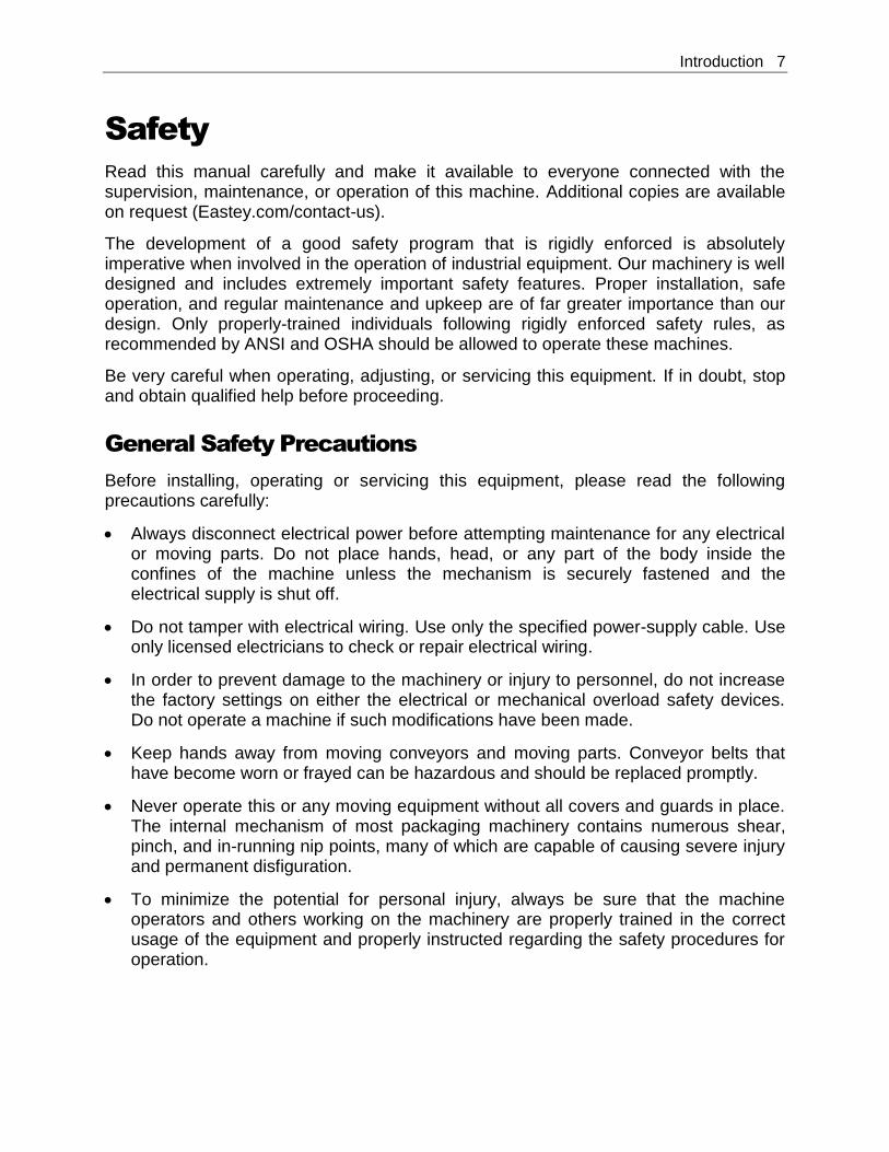
Safety
Read this manual carefully and make it available to everyone connected with the supervision, maintenance, or operation of this machine. Additional copies are available on request (Eastey.com/contact-us).
The development of a good safety program that is rigidly enforced is absolutely imperative when involved in the operation of industrial equipment. Our machinery is well designed and includes extremely important safety features. Proper installation, safe operation, and regular maintenance and upkeep are of far greater importance than our design. Only properly-trained individuals following rigidly enforced safety rules, as recommended by ANSI and OSHA should be allowed to operate these machines.
Be very careful when operating, adjusting, or servicing this equipment. If in doubt, stop and obtain qualified help before proceeding.
General Safety Precautions
Before installing, operating or servicing this equipment, please read the following precautions carefully:
Always disconnect electrical power before attempting maintenance for any electrical or moving parts. Do not place hands, head, or any part of the body inside the confines of the machine unless the mechanism is securely fastened and the electrical supply is shut off.
Do not tamper with electrical wiring. Use only the specified power-supply cable. Use only licensed electricians to check or repair electrical wiring.
In order to prevent damage to the machinery or injury to personnel, do not increase the factory settings on either the electrical or mechanical overload safety devices. Do not operate a machine if such modifications have been made.
Keep hands away from moving conveyors and moving parts. Conveyor belts that have become worn or frayed can be hazardous and should be replaced promptly.
Never operate this or any moving equipment without all covers and guards in place. The internal mechanism of most packaging machinery contains numerous shear, pinch, and in-running nip points, many of which are capable of causing severe injury and permanent disfiguration.
To minimize the potential for personal injury, always be sure that the machine operators and others working on the machinery are properly trained in the correct usage of the equipment and properly instructed regarding the safety procedures for operation.
8 Introduction
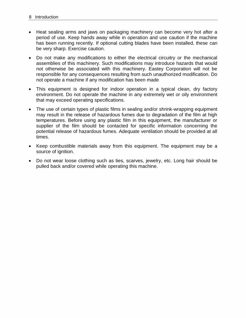
Heat sealing arms and jaws on packaging machinery can become very hot after a period of use. Keep hands away while in operation and use caution if the machine has been running recently. If optional cutting blades have been installed, these can be very sharp. Exercise caution.
Do not make any modifications to either the electrical circuitry or the mechanical assemblies of this machinery. Such modifications may introduce hazards that would not otherwise be associated with this machinery. Eastey Corporation will not be responsible for any consequences resulting from such unauthorized modification. Do not operate a machine if any modification has been made
This equipment is designed for indoor operation in a typical clean, dry factory environment. Do not operate the machine in any extremely wet or oily environment that may exceed operating specifications.
The use of certain types of plastic films in sealing and/or shrink-wrapping equipment may result in the release of hazardous fumes due to degradation of the film at high temperatures. Before using any plastic film in this equipment, the manufacturer or supplier of the film should be contacted for specific information concerning the potential release of hazardous fumes. Adequate ventilation should be provided at all times.
Keep combustible materials away from this equipment. The equipment may be a source of ignition.
Do not wear loose clothing such as ties, scarves, jewelry, etc. Long hair should be pulled back and/or covered while operating this machine.
Introduction 9
Introduction
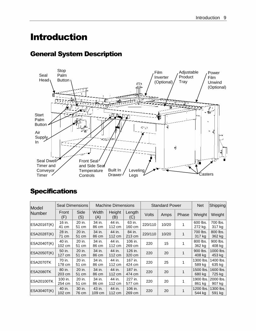
General System Description
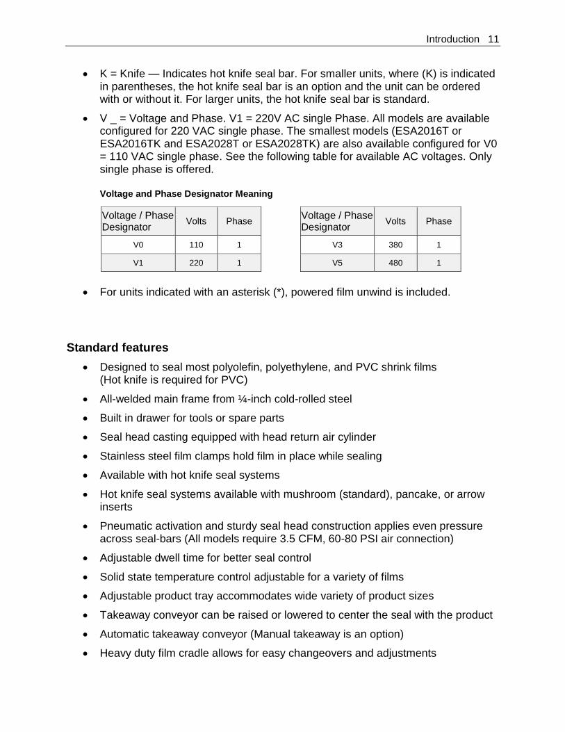
Specifications
Model Number
Seal Dimensions Machine Dimensions Standard Power Net Shipping
Front (F)
Side (S)
Width (A)
Height (B)
Length (C)
Volts Amps Phase Weight Weight
ESA2016T(K) 16 in. 41 cm
20 in. 51 cm
34 in. 86 cm
44 in. 112 cm
63 in. 160 cm
220/110 10/20 1 600 lbs. 272 kg.
700 lbs. 317 kg
ESA2028T(K) 28 in. 71 cm
20 in. 51 cm
34 in. 86 cm
44 in. 112 cm
84 in. 213 cm
220/110 10/20 1 700 lbs. 317 kg
800 lbs. 362 kg
ESA2040T(K) 40 in.
102 cm 20 in. 51 cm
34 in. 86 cm
44 in. 112 cm
106 in. 269 cm
220 15 1 800 lbs. 362 kg
900 lbs. 408 kg
ESA2050T(K) 50 in.
127 cm 20 in. 51 cm
34 in. 86 cm
44 in. 112 cm
126 in. 320 cm
220 20 1 900 lbs. 408 kg
1000 lbs. 453 kg
ESA2070TK 70 in.
178 cm 20 in. 51 cm
34 in. 86 cm
44 in. 112 cm
167 in. 424 cm
220 25 1 1300 lbs. 589 kg
1400 lbs. 635 kg
ESA2080TK 80 in.
203 cm 20 in. 51 cm
34 in. 86 cm
44 in. 112 cm
187 in. 474 cm
220 20 1 1500 lbs. 680 kg
1600 lbs. 725 kg
ESA20100TK 100 in. 254 cm
20 in. 51 cm
34 in. 86 cm
44 in. 112 cm
227 in. 577 cm
220 20 1 1900 lbs. 861 kg
2000 lbs. 907 kg
ESA3040T(K) 40 in.
102 cm 30 in. 76 cm
43 in. 109 cm
44 in. 112 cm
106 in. 269 cm
220 20 1 1200 lbs. 544 kg
1300 lbs. 591 kg
Seal Head
Stop Palm Button
Start Palm Button
Adjustable Product Tray
Air Supply In
Front Seal and Side Seal Temperature Controls
Built In Drawer
Leveling Legs
Film Inverter (Optional)
Power Film Unwind (Optional)
Casters
Seal Dwell Timer and Conveyor Timer
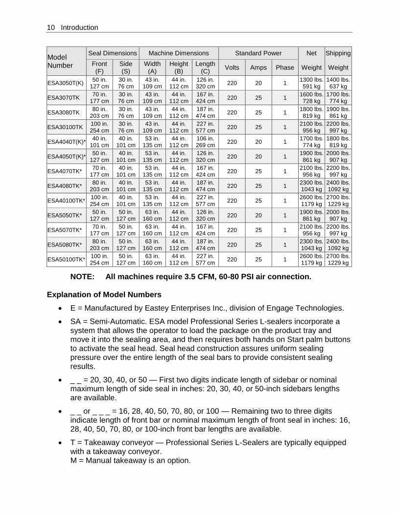
10 Introduction
Model Number
Seal Dimensions Machine Dimensions Standard Power Net Shipping
Front (F)
Side (S)
Width (A)
Height (B)
Length (C)
Volts Amps Phase Weight Weight
ESA3050T(K) 50 in.
127 cm 30 in. 76 cm
43 in. 109 cm
44 in. 112 cm
126 in. 320 cm
220 20 1 1300 lbs. 591 kg
1400 lbs. 637 kg
ESA3070TK 70 in.
177 cm 30 in. 76 cm
43 in. 109 cm
44 in. 112 cm
167 in. 424 cm
220 25 1 1600 lbs. 728 kg
1700 lbs. 774 kg
ESA3080TK 80 in.
203 cm 30 in. 76 cm
43 in. 109 cm
44 in. 112 cm
187 in. 474 cm
220 25 1 1800 lbs. 819 kg
1900 lbs. 861 kg
ESA30100TK 100 in. 254 cm
30 in. 76 cm
43 in. 109 cm
44 in. 112 cm
227 in. 577 cm
220 25 1 2100 lbs. 956 kg
2200 lbs. 997 kg
ESA4040T(K)* 40 in.
101 cm 40 in.
101 cm 53 in.
135 cm 44 in.
112 cm 106 in. 269 cm
220 20 1 1700 lbs. 774 kg
1800 lbs. 819 kg
ESA4050T(K)* 50 in.
127 cm 40 in.
101 cm 53 in.
135 cm 44 in.
112 cm 126 in. 320 cm
220 20 1 1900 lbs. 861 kg
2000 lbs. 907 kg
ESA4070TK* 70 in.
177 cm 40 in.
101 cm 53 in.
135 cm 44 in.
112 cm 167 in. 424 cm
220 25 1 2100 lbs. 956 kg
2200 lbs. 997 kg
ESA4080TK* 80 in.
203 cm 40 in.
101 cm 53 in.
135 cm 44 in.
112 cm 187 in. 474 cm
220 25 1 2300 lbs. 1043 kg
2400 lbs. 1092 kg
ESA40100TK* 100 in. 254 cm
40 in. 101 cm
53 in. 135 cm
44 in. 112 cm
227 in. 577 cm
220 25 1 2600 lbs. 1179 kg
2700 lbs. 1229 kg
ESA5050TK* 50 in.
127 cm 50 in.
127 cm 63 in.
160 cm 44 in.
112 cm 126 in. 320 cm
220 20 1 1900 lbs. 861 kg
2000 lbs. 907 kg
ESA5070TK* 70 in.
177 cm 50 in.
127 cm 63 in.
160 cm 44 in.
112 cm 167 in. 424 cm
220 25 1 2100 lbs. 956 kg
2200 lbs. 997 kg
ESA5080TK* 80 in.
203 cm 50 in.
127 cm 63 in.
160 cm 44 in.
112 cm 187 in. 474 cm
220 25 1 2300 lbs. 1043 kg
2400 lbs. 1092 kg
ESA50100TK* 100 in. 254 cm
50 in. 127 cm
63 in. 160 cm
44 in. 112 cm
227 in. 577 cm
220 25 1 2600 lbs. 1179 kg
2700 lbs. 1229 kg
NOTE: All machines require 3.5 CFM, 60-80 PSI air connection. Explanation of Model Numbers
E = Manufactured by Eastey Enterprises Inc., division of Engage Technologies.
SA = Semi-Automatic. ESA model Professional Series L-sealers incorporate a system that allows the operator to load the package on the product tray and move it into the sealing area, and then requires both hands on Start palm buttons to activate the seal head. Seal head construction assures uniform sealing pressure over the entire length of the seal bars to provide consistent sealing results.
_ _ = 20, 30, 40, or 50 — First two digits indicate length of sidebar or nominal maximum length of side seal in inches: 20, 30, 40, or 50-inch sidebars lengths are available.
_ _ or _ _ _ = 16, 28, 40, 50, 70, 80, or 100 — Remaining two to three digits indicate length of front bar or nominal maximum length of front seal in inches: 16, 28, 40, 50, 70, 80, or 100-inch front bar lengths are available.
T = Takeaway conveyor — Professional Series L-Sealers are typically equipped with a takeaway conveyor. M = Manual takeaway is an option.
Introduction 11
K = Knife — Indicates hot knife seal bar. For smaller units, where (K) is indicated in parentheses, the hot knife seal bar is an option and the unit can be ordered with or without it. For larger units, the hot knife seal bar is standard.
V _ = Voltage and Phase. V1 = 220V AC single Phase. All models are available configured for 220 VAC single phase. The smallest models (ESA2016T or ESA2016TK and ESA2028T or ESA2028TK) are also available configured for V0 = 110 VAC single phase. See the following table for available AC voltages. Only single phase is offered.
Voltage and Phase Designator Meaning
Voltage / Phase Designator
Volts Phase Voltage / Phase Designator
Volts Phase
V0 110 1 V3 380 1
V1 220 1 V5 480 1
For units indicated with an asterisk (*), powered film unwind is included.
Standard features
Designed to seal most polyolefin, polyethylene, and PVC shrink films (Hot knife is required for PVC)
All-welded main frame from ¼-inch cold-rolled steel
Built in drawer for tools or spare parts
Seal head casting equipped with head return air cylinder
Stainless steel film clamps hold film in place while sealing
Available with hot knife seal systems
Hot knife seal systems available with mushroom (standard), pancake, or arrow inserts
Pneumatic activation and sturdy seal head construction applies even pressure across seal-bars (All models require 3.5 CFM, 60-80 PSI air connection)
Adjustable dwell time for better seal control
Solid state temperature control adjustable for a variety of films
Adjustable product tray accommodates wide variety of product sizes
Takeaway conveyor can be raised or lowered to center the seal with the product
Automatic takeaway conveyor (Manual takeaway is an option)
Heavy duty film cradle allows for easy changeovers and adjustments
12 Introduction
Adjustable pin perforator provides air evacuation
Side seal size from 20 in. to 50 in.; front seal size from 16 in. to 100 in.
Maximum film width up to 44 inches
Maximum film roll O.D. up to 12 inches; 10 inches with power unwind
Custom two-part epoxy finish resists scratching
Heavy duty casters for transportation within plant
Available in 110V, 220V, or optional 480V
Easy to use design requires minimal training and maintenance
Made in the USA
Options
Power film unwind
Film inverter
Hot knife inserts
Stainless steel and left-hand models available
Lower conveyor (2" maximum)
Custom product guides or product tray
Introduction 13
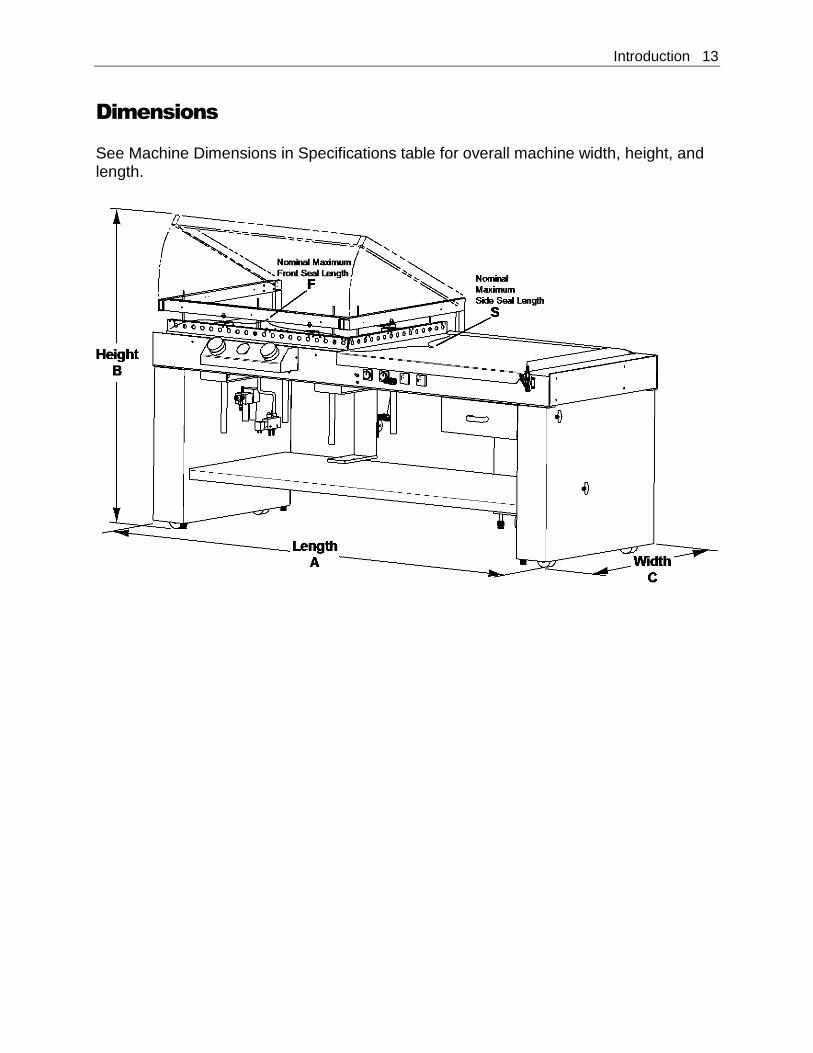
Dimensions
See Machine Dimensions in Specifications table for overall machine width, height, and length.
14 Installation
Unpacking
Thoroughly inspect the equipment and packaging immediately on arrival. Carefully remove the outer protective shipping wrapper. Inspect the machine for any damage that may have occurred during transit. If goods are received short or in damaged condition, it is important that you notify the carrier’s driver before they leave your company and insist on a notation of the loss or damage across the bill of lading. Otherwise no claim can be enforced against the transportation company. Please note that a copy of this document is attached to the outside of every crate. If concealed loss or damage is discovered, notify your carrier at once and request, insist, on an inspection. This is absolutely necessary. A concealed damage report must be made within ten (10) days of delivery of shipment. Unless you do this, the carrier will not entertain any claim for loss or damage. The agent will make an inspection and grant a concealed damage notation. If you give the transportation company a clear receipt for the goods that have been damaged or lost in transit, you do so at your own risk and expense. All claims must be filled within five (5) months of the delivery date or the carrier will not accept them. We are willing to assist you in every reasonable manner to help you collect claims for loss or damage. However, this willingness on Eastey’s part does not make Eastey or its parent or related companies responsible for collections or claims or replacement of equipment damaged or lost in transit.
Loading and Unloading Instructions
Equipment is crated and will require a forklift to unload.
Installation 15
Installation
Lift the machine up and off of the shipping pallet.
CAUTION! The ESA series L-sealer is heavy and will require a forklift, floor crane, or several people to move safely off the shipping pallet. Use proper equipment when lifting the L-sealer and ensure it is secure and will not shift while being moved off the shipping pallet.
Place the sealer in the desired location with the required electrical power source available. (See power requirements for the specific model in the Specifications table.) Make sure the electrical wiring is adequate to provide the required voltage. If the voltage provided is too low, the equipment will not operate correctly. Selecting the proper location is one of the most important considerations for initial setup. When selecting the location, take into consideration the following factors.
1. Adequate power supply nearby?
2. Where is the sealer in relation to the power source? Source of air at required CFM flow and PSI pressure?
3. Where is the sealer in relation to the tunnel and any conveyor(s) necessary to move the wrapped product? (Alignment with packaging line.)
4. Convenience for the operator. If there is any doubt, get qualified assistance with your initial installation.
Location Requirements
When installing the L-sealer please be aware of the following considerations:
1. The surface on which it is located is flat and level.
2. Conveyor or packing table height.
3. Alignment with packaging line. When the L-sealer is positioned in the operating location you will need access to:
1. Control panel switches: On/Off switch, dwell timer, conveyor timer.
2. Height and width adjustments.
3. Film unwinder.
16 Installation
For units equipped with a takeaway conveyor at the exit of the L-sealer, provision should be made for exiting packages. For example, a table or bin where packages that have been sealed will be placed until they can be picked up, or a conveyor that will move them to the tunnel. If the L-sealer is part of a longer packaging line, take into consideration the table and conveyor height in relation to adjacent machinery. The machine should be placed on a flat, level floor so that it does not rock or move. We recommend that the machine be securely locked in place when used. Set up the L-sealer and move it to its location. The casters allow easy movement over smooth flat surfaces. If you need to lift the unit to move it, you will need to use a pallet jack, floor crane, or fork lift to move it to its location.
CAUTION! If the L-sealer must be lifted for moving, use proper equipment when lifting and moving it to ensure it is secure and will not shift.
When the L-sealer has been moved to its location, use the levers on the casters to lock the wheels to prevent rolling and keep the unit in place. A power cord (with optional electrical plug) should be installed by a licensed electrician.
CAUTION! Before operating, ensure the following: 1. All shipping ties are removed. 2. All personnel are clear of the equipment. 3. Electrician has stated that all electrical work is complete. 4. Adjust all controls according to the settings sheet. 5. Air line is connected to the regulator and verify power
supply of 60-80 PSI, 3.5 CFM. Refer to instructions in the Operation section for instructions to power up or shut down the machine.
Operation 17
Operation
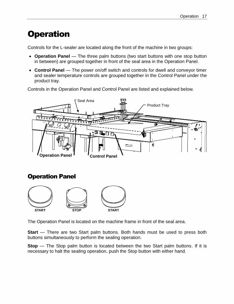
Controls for the L-sealer are located along the front of the machine in two groups:
Operation Panel — The three palm buttons (two start buttons with one stop button in between) are grouped together in front of the seal area in the Operation Panel.
Control Panel — The power on/off switch and controls for dwell and conveyor timer and sealer temperature controls are grouped together in the Control Panel under the product tray.
Controls in the Operation Panel and Control Panel are listed and explained below.
Operation Panel
The Operation Panel is located on the machine frame in front of the seal area. Start — There are two Start palm buttons. Both hands must be used to press both buttons simultaneously to perform the sealing operation.
Stop — The Stop palm button is located between the two Start palm buttons. If it is necessary to halt the sealing operation, push the Stop button with either hand.
Operation Panel
Product Tray
Control Panel
Seal Area
START STARTSTOP
18 Operation
Control Panel
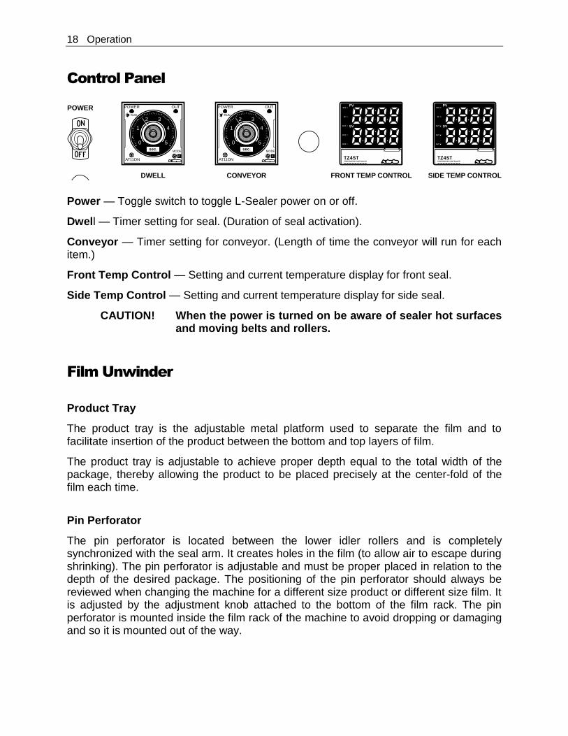
Power — Toggle switch to toggle L-Sealer power on or off.
Dwell — Timer setting for seal. (Duration of seal activation).
Conveyor — Timer setting for conveyor. (Length of time the conveyor will run for each item.)
Front Temp Control — Setting and current temperature display for front seal.
Side Temp Control — Setting and current temperature display for side seal.
CAUTION! When the power is turned on be aware of sealer hot surfaces and moving belts and rollers.
Film Unwinder
Product Tray
The product tray is the adjustable metal platform used to separate the film and to facilitate insertion of the product between the bottom and top layers of film.
The product tray is adjustable to achieve proper depth equal to the total width of the package, thereby allowing the product to be placed precisely at the center-fold of the film each time.
Pin Perforator
The pin perforator is located between the lower idler rollers and is completely synchronized with the seal arm. It creates holes in the film (to allow air to escape during shrinking). The pin perforator is adjustable and must be proper placed in relation to the depth of the desired package. The positioning of the pin perforator should always be reviewed when changing the machine for a different size product or different size film. It is adjusted by the adjustment knob attached to the bottom of the film rack. The pin perforator is mounted inside the film rack of the machine to avoid dropping or damaging and so it is mounted out of the way.
PVSV2
AT
OUT
EV1
EV2
SV
TZ4STTEMPERATURE CONT ROLLER
PVSV2
AT
OUT
EV1
EV2
SV
TZ4STTEMPERATURE CONT ROLLER
0
1
2 3
4
5
POWER OUT
MODE
AT11DN
RUN
A
0
1
2 3
4
5
POWER OUT
MODE
AT11DN
RUN
A
DWELL CONVEYOR FRONT TEMP CONTROL SIDE TEMP CONTROL
POWER
sec. sec.
Operation 19
Film Brake
The film brake is positioned at the front end of the cradle rollers and creates a drag that maintains tension on the film as the film is dispensed. The operator should from time to time re-check the setting of the film brake for proper tension. The film brake’s purpose is to reduce overruns or slack in the film.
Mounting Film
Standard Cradle-Mount (Unpowered) Film Unwinder
Select the proper width of center-fold film for the product being packaged, taking into account the width and height of the package. With the package properly positioned within the film in the sealing area, allow sufficient film to overlap the sealing bars so that a seal can easily be made without possibility of openings due to insufficient film coverage.
Place the film roll on the rollers of the cradle-mount film unwinder. (See the illustration on the following page.) Place the center-fold away from the operator, to the back of the machine. Position the film roll on the rollers and tighten the upright bolts on the film rack collars to hold the film roll in position.
Decide whether the film is an A or B wind, and then thread it through and around the idler rollers and the pin perforator. (See the following illustration.) When threading the film, make sure to pull excess film through the rollers, across the product tray and into the sealing area to ensure sufficient film to begin. When you have threaded the film, separate the top film from the bottom and insert the product tray between the film top and bottom. Make sure that the center-fold of the film is at the back of the product tray. This allows the operator to insert product on the product tray between the top and bottom layers of film to prepare to move the product and film into the sealing area. Do not place product in the first few bags formed by the sealer: they will not have any perforation holes in them (because the sealer and pin perforator work together). Perforation is required to allow air to vacate when the product passes through the shrink tunnel.
20 Operation
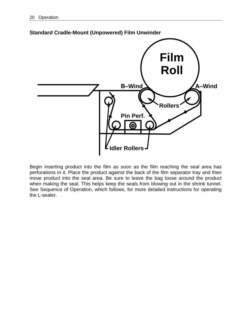
Standard Cradle-Mount (Unpowered) Film Unwinder
Begin inserting product into the film as soon as the film reaching the seal area has perforations in it. Place the product against the back of the film separator tray and then move product into the seal area. Be sure to leave the bag loose around the product when making the seal. This helps keep the seals from blowing out in the shrink tunnel. See Sequence of Operation, which follows, for more detailed instructions for operating the L-sealer.
FilmRoll
A–WindB–Wind
Rollers
Pin Perf.
Idler Rollers
Operation 21
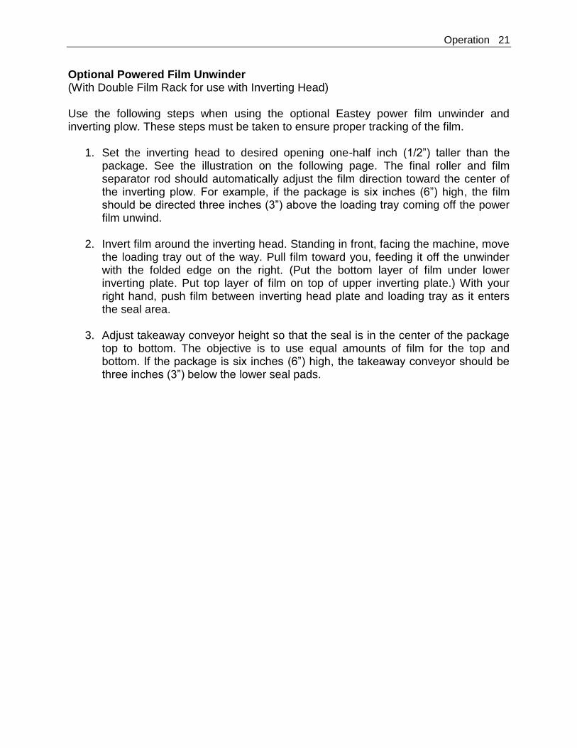
Optional Powered Film Unwinder (With Double Film Rack for use with Inverting Head) Use the following steps when using the optional Eastey power film unwinder and inverting plow. These steps must be taken to ensure proper tracking of the film.
1. Set the inverting head to desired opening one-half inch (1/2”) taller than the package. See the illustration on the following page. The final roller and film separator rod should automatically adjust the film direction toward the center of the inverting plow. For example, if the package is six inches (6”) high, the film should be directed three inches (3”) above the loading tray coming off the power film unwind.
2. Invert film around the inverting head. Standing in front, facing the machine, move
the loading tray out of the way. Pull film toward you, feeding it off the unwinder with the folded edge on the right. (Put the bottom layer of film under lower inverting plate. Put top layer of film on top of upper inverting plate.) With your right hand, push film between inverting head plate and loading tray as it enters the seal area.
3. Adjust takeaway conveyor height so that the seal is in the center of the package top to bottom. The objective is to use equal amounts of film for the top and bottom. If the package is six inches (6”) high, the takeaway conveyor should be three inches (3”) below the lower seal pads.
22 Operation
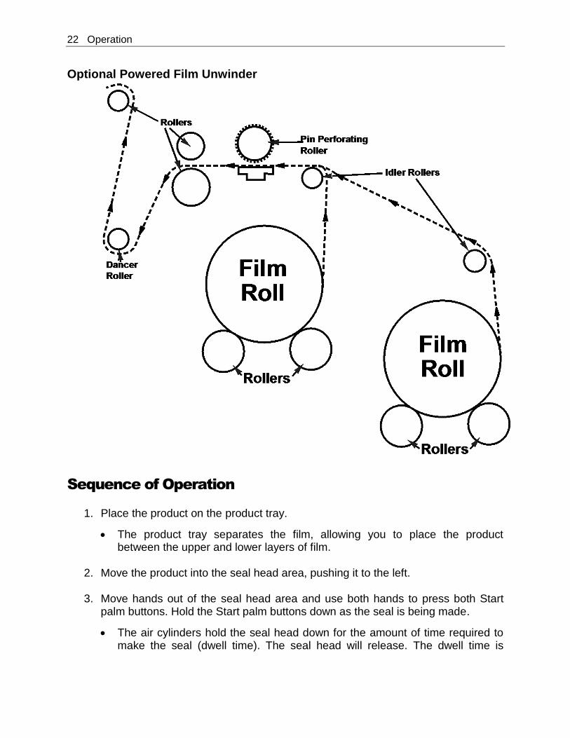
Optional Powered Film Unwinder
Sequence of Operation
1. Place the product on the product tray.
The product tray separates the film, allowing you to place the product between the upper and lower layers of film.
2. Move the product into the seal head area, pushing it to the left.
3. Move hands out of the seal head area and use both hands to press both Start
palm buttons. Hold the Start palm buttons down as the seal is being made.
The air cylinders hold the seal head down for the amount of time required to make the seal (dwell time). The seal head will release. The dwell time is
Operation 23
adjustable from one (1) to five (5) seconds and is indicated on the Dwell timer indicator, which is located closest to the Power switch under the product tray.
4. Once the seal is formed completely and the seal head automatically releases.
The sealed product is removed by the takeaway conveyor, and the next Item can be moved into position for sealing.
The takeaway conveyor runs for the specified amount of time required to move the sealed product onward out of the sealing area. The amount of time the conveyor runs is adjustable from one (1) to five (5) seconds and is indicated on the Conveyor timer indicator, located next to the dwell timer indicator under the product tray.
Prepare the next item to be sealed, placing it on the product tray between upper and lower layers of film as the takeaway conveyor moves the sealed product away.
NOTE: If there is too much tension on the film while the bag is being
sealed, the seals will be more likely to be weak or blow out in the seal area while moving through the shrink tunnel.
24 Adjustments
Adjustments
Element Pulse Switch Adjustment
The dwell time should not begin until the seal head is within one-quarter-inch (¼”) or less of the film to be sealed. Adjustment has been set correctly when sealing begins just as the seal bar comes into contact with the lower pads.
Seal Head Position Adjustment
Seal heads have been factory adjusted for equal sealing pressure throughout the length of both the front and the side seal bars. If an adjustment is required, however, use the following procedure.
1. Disconnect the L-sealer power plug from the electrical power source.
2. Loosen seal head adjustment screws to reposition seal head.
3. Reposition seal head to correct alignment and position.
4. Re-tighten the mounting screws securely to retain the proper adjustment.
Seal Pad Pressure Adjustment for Head Return Cylinder
Uniform pressure between the sealing elements and the sealing pads must always be maintained in order to obtain an even seal and to prevent heating-element hotspots and premature burnout. The adjustment should be checked periodically and should always be checked when sealing gaps occur.
1. Disconnect the sealer power plug from the electrical power source.
2. Supporting the seal head in the up position, loosen the four set screws for the head return cylinder. Gently lower the seal head to rest on the lower seal pads.
3. With the seal head resting on the lower pads, shim up the film clamps so that the inserts are resting on the lower pads. Make sure there are no air gaps, and then tighten the head casting bolts.
4. Adjust the seal head.
5. Go to the rear of the L-sealer. Make sure the head cylinder is straight from front to back. Pull the air cylinder bracket the full length of the air cylinder. Tighten the 5/16-inch set screws.
6. Cycle the seal head up and down. Adjust set screws on head return cylinders for proper head speed and cushion.
Adjustments 25
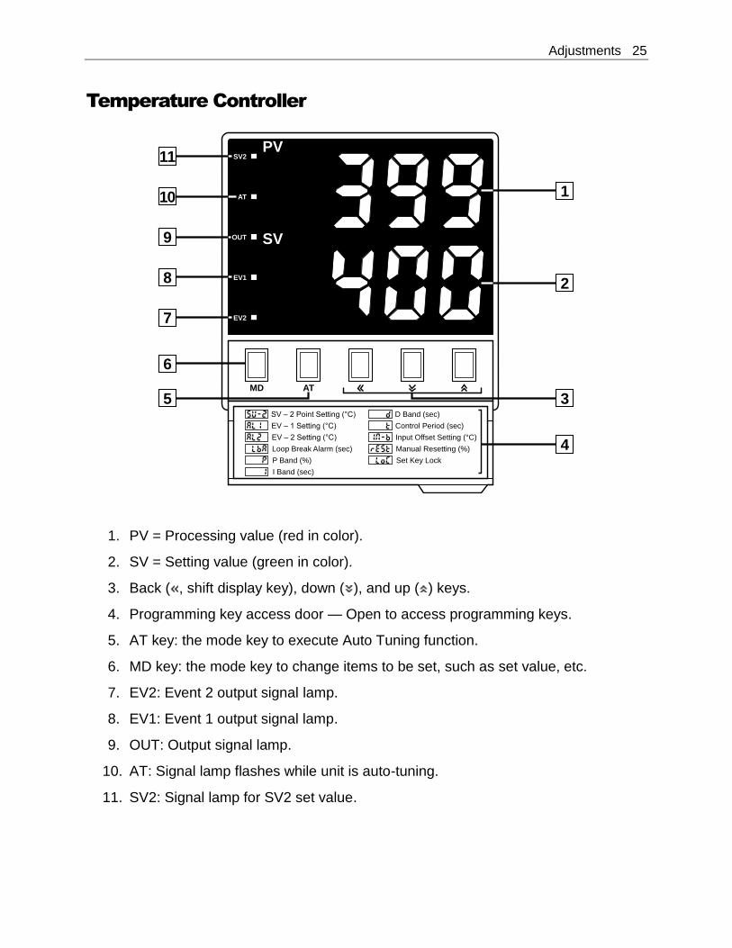
Temperature Controller
1. PV = Processing value (red in color).
2. SV = Setting value (green in color).
3. Back ( , shift display key), down ( ), and up ( ) keys.
4. Programming key access door — Open to access programming keys.
5. AT key: the mode key to execute Auto Tuning function.
6. MD key: the mode key to change items to be set, such as set value, etc.
7. EV2: Event 2 output signal lamp.
8. EV1: Event 1 output signal lamp.
9. OUT: Output signal lamp.
10. AT: Signal lamp flashes while unit is auto-tuning.
11. SV2: Signal lamp for SV2 set value.
PVSV2
AT
OUT
EV1
EV2
SV
MD AT
SV – 2 Point Setting (°C)
EV – 1 Setting (°C)
EV – 2 Setting (°C)
Loop Break Alarm (sec)
P Band (%)
D Band (sec)
Control Period (sec)
Input Offset Setting (°C)
Manual Resetting (%)
Set Key Lock
I Band (sec)
1
2
3
4
5
6
7
8
9
10
11
26 Adjustments
To Change the Set Value
1. Press the left-arrow ( ) button and a digit will begin to flash. The flashing digit
indicates the digit whose value can be changed by pressing the down- ( ) or up-arrow ( ) buttons.
2. If necessary, press the left- ( ) or right-arrow ( ) to shift to the place of the digit
that needs to be changed. (The digit to the left or right will begin flashing.)
3. Press up ( ) or down ( ), as required to change the flashing digit to the required value.
4. Repeat instructions 2 and 3 above as necessary until all digits have been set to
the required value, and then press the MD button. No digits will be flashing, the new value entered is applied.
To Change the Set Value for Over Temperature
Over temperature is factory set to 500° F, but can be adjusted if required for your sealing application. PV, the Process Value is the actual temperature reading at the sealing elements. PV and SV are mentioned in this procedure, but they are only displayed at the beginning of the procedure.
1. Press and hold the MD button until SV-2 is displayed.
2. Press the MD button (do not hold it down) repeatedly to scroll through the menu until LOC is displayed.
3. Press the left-arrow ( ) button. (ON will begin flashing.)
4. Press the down-arrow button ( ). (ON will turn to OFF and OFF will be flashing.)
5. Press the MD button. (OFF will stop flashing.)
6. Press MD again. (This will bring you back to SV-2.)
7. Press MD again until AL-1 is displayed.
8. AL-1 is set to 500°.
Adjustments 27
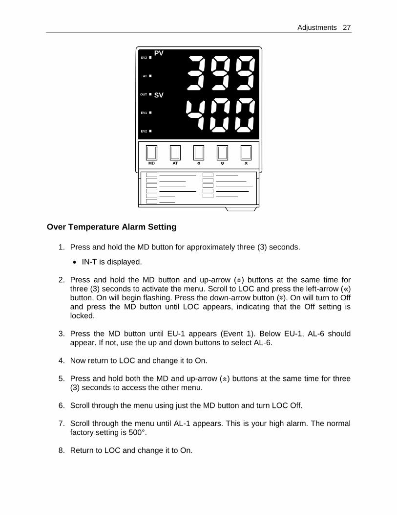
Over Temperature Alarm Setting
1. Press and hold the MD button for approximately three (3) seconds.
IN-T is displayed.
2. Press and hold the MD button and up-arrow ( ) buttons at the same time for three (3) seconds to activate the menu. Scroll to LOC and press the left-arrow ( ) button. On will begin flashing. Press the down-arrow button ( ). On will turn to Off and press the MD button until LOC appears, indicating that the Off setting is locked.
3. Press the MD button until EU-1 appears (Event 1). Below EU-1, AL-6 should
appear. If not, use the up and down buttons to select AL-6.
4. Now return to LOC and change it to On.
5. Press and hold both the MD and up-arrow ( ) buttons at the same time for three (3) seconds to access the other menu.
6. Scroll through the menu using just the MD button and turn LOC Off.
7. Scroll through the menu until AL-1 appears. This is your high alarm. The normal
factory setting is 500°.
8. Return to LOC and change it to On.
PVSV2
AT
OUT
EV1
EV2
SV
MD AT
28 Adjustments
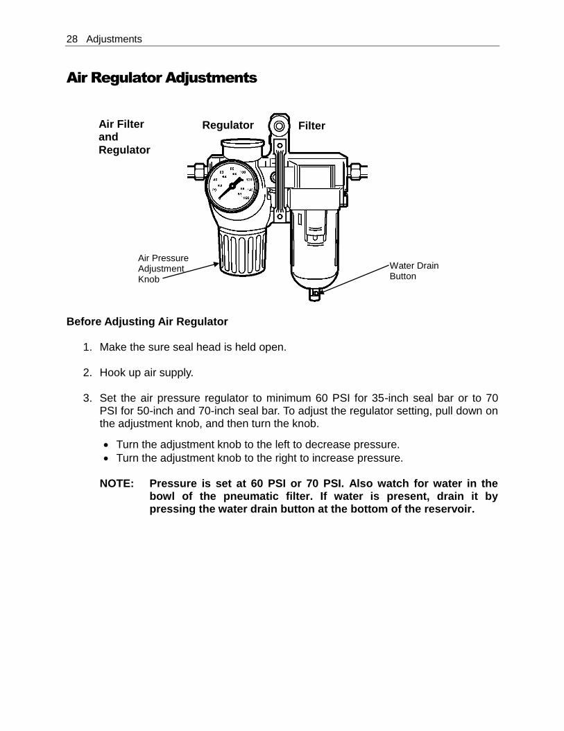
Air Regulator Adjustments
Before Adjusting Air Regulator
1. Make the sure seal head is held open.
2. Hook up air supply.
3. Set the air pressure regulator to minimum 60 PSI for 35-inch seal bar or to 70 PSI for 50-inch and 70-inch seal bar. To adjust the regulator setting, pull down on the adjustment knob, and then turn the knob.
Turn the adjustment knob to the left to decrease pressure.
Turn the adjustment knob to the right to increase pressure.
NOTE: Pressure is set at 60 PSI or 70 PSI. Also watch for water in the bowl of the pneumatic filter. If water is present, drain it by pressing the water drain button at the bottom of the reservoir.
Filter Air Filter and
Regulator
Air Pressure Adjustment Knob
Water Drain Button
Regulator
Maintenance 29
Maintenance The Eastey ESA Professional Series Semi-Automatic L-Sealer will provide many hours of maintenance-free operation. There are a few items that may require attention from time to time.
Preventative Maintenance
Daily Maintenance
On hot knife sealers, heat the seal bars up to temperature. (Be careful of the
coatings on the bars and inserts.) Then, using a soft cloth, wipe the seal surfaces clean. Never use anything abrasive.
Weekly or Monthly Maintenance
Check the condition of the Teflon tape and the silicone sponge rubber in the
lower seal bar. Replace as necessary.
Check the seal head alignment and gap. Refer to the service adjustment section of this User Guide and make adjustments as needed.
Check the conveyor drive belt condition. Replace it if necessary.
Check the conveyor belt for nicks or tears. Check if belt is tracking and moving
smoothly. Repair or replace as needed.
Check that the conveyor lift jack moves the conveyor up and down smoothly. Lubricate and adjust as needed.
Check the film rack rollers for excessive end play and so that they turn freely.
Check that the film brake works. Adjust as needed.
Check the condition of the power cord for wear. (Is it exposed to traffic?)
Check the hot knife seal heads’ ability to maintain the set temperature. If not, refer to maintenance instructions in this User Guide.
Check for loose fasteners. Tighten as necessary.
Check the condition of all warning and instruction labels. Replace as necessary.
30 Maintenance
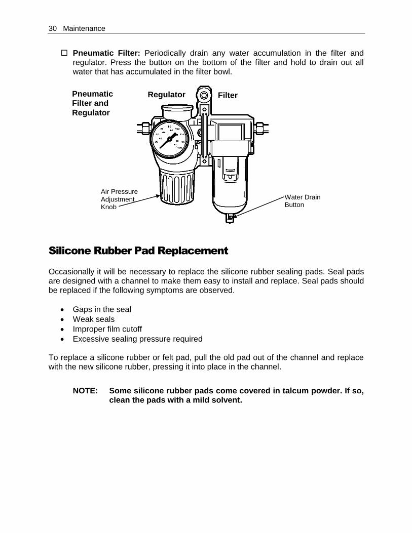
Pneumatic Filter: Periodically drain any water accumulation in the filter and regulator. Press the button on the bottom of the filter and hold to drain out all water that has accumulated in the filter bowl.
Silicone Rubber Pad Replacement
Occasionally it will be necessary to replace the silicone rubber sealing pads. Seal pads are designed with a channel to make them easy to install and replace. Seal pads should be replaced if the following symptoms are observed.
Gaps in the seal
Weak seals
Improper film cutoff
Excessive sealing pressure required To replace a silicone rubber or felt pad, pull the old pad out of the channel and replace with the new silicone rubber, pressing it into place in the channel.
NOTE: Some silicone rubber pads come covered in talcum powder. If so,
clean the pads with a mild solvent.
Filter Pneumatic Filter and
Regulator
Air Pressure Adjustment Knob
Water Drain Button
Regulator
Maintenance 31
Changing Hot Knife Inserts and Cutting Rules
1. Disconnect the L-sealer power plug from the electrical power source.
CAUTION! Always be aware of the cutting edges while replacing the
knife edges. Handle the knife blades carefully.
2. Remove the #10-32 screws holding the inner side film clamp and remove the #10-32 screws holding the outer front film clamp.
NOTE: One #10-32 screw is behind the aluminum arm casting. This does
not need to be removed. Push the product tray in all the way. Swing the film clamp down and to the right over the product tray, then pull it out and rest the film clamp on the product tray.
3. Remove the #8-32 flat head screw on both side-seal and front-seal bars.
4. Remove the insert and cutting rule, both at the same time.
5. Place the replacement cutting rules into the new inserts, both at the same time,
ensuring that the beveled edge is in the corner.
6. Push the beveled edges together.
NOTE: The inside beveled edges of the cutting rule need to come together. The outsides do not. Be sure the cutting rules are touching.
7. Install the #8-32 flat head screws, but do not tighten them at this point.
8. Heat the seal bar up to the set point.
9. Adjust insert and cutting rule if they separate at the corner.
10. Tighten the #8-32 flat head screws while the seal bars are hot.
11. Turn off heat and allow the sealer to cool down, and then reinstall film clamps.
Takeaway Conveyor Maintenance and Replacement
From time to time it will be necessary to disassemble the conveyor when it requires an adjustment for a different product size or if worn parts need to be replaced or for general maintenance. Instructions provided in this user guide are very general. If these
32 Maintenance
generalized instructions do not address your specific conveyor issue, contact a certified representative of Eastey or contact Eastey Enterprises directly (Eastey.com/contact-us).
Replacing the Takeaway Conveyor Motor
NOTE: This procedure requires an Allen or hex wrench, and a 7/16-inch
box-end wrench.
1. Disconnect the L-sealer power plug from the electrical power source.
2. Disconnect wires # 14 and # 16 from inside the panel and pull them out. Note the color of wires and where they are connected.
NOTE: Wiring color connections to the conveyor motor.
Red and yellow are together and capped.
Brown, purple, and orange are together and capped.
Black is connected to black for power.
White is connected to white for power.
Green is connected to green to ground or motor ground.
3. Loosen the ¼-20 drive roller adjustment bolts and remove the timing belt. Remove the timing pulley from the motor (requires an Allen or hex wrench).
4. Remove the three ¼-20 bolts. These hold the motor in place. As the last bolt is
removed, hold onto the motor so it does not fall. (Bolt removal requires 7/16-inch box end wrench.)
5. Place the new conveyor motor in place of the conveyor motor removed, and
install the ¼-20 bolts.
6. Re-install the timing pulley. Make sure it is not rubbing against the conveyor frame, and then tighten both set screws.
7. Reinstall the timing belt. Tighten the ¼-20 drive roller adjustment bolts.
Reconnect the power wires #14 and # 16. Refer to the wiring color connections note on the preceding page to complete motor wiring connections.
8. Refer to the instructions for Tracking the Takeaway Conveyor Belt that follow.
Replacing the Takeaway Conveyor Belt
1. Disconnect the L-sealer power plug from the electrical power source.
Maintenance 33
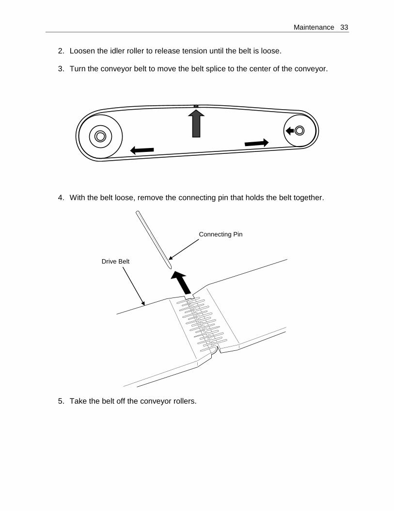
2. Loosen the idler roller to release tension until the belt is loose.
3. Turn the conveyor belt to move the belt splice to the center of the conveyor.
4. With the belt loose, remove the connecting pin that holds the belt together.
5. Take the belt off the conveyor rollers.
Connecting Pin
Drive Belt
34 Maintenance
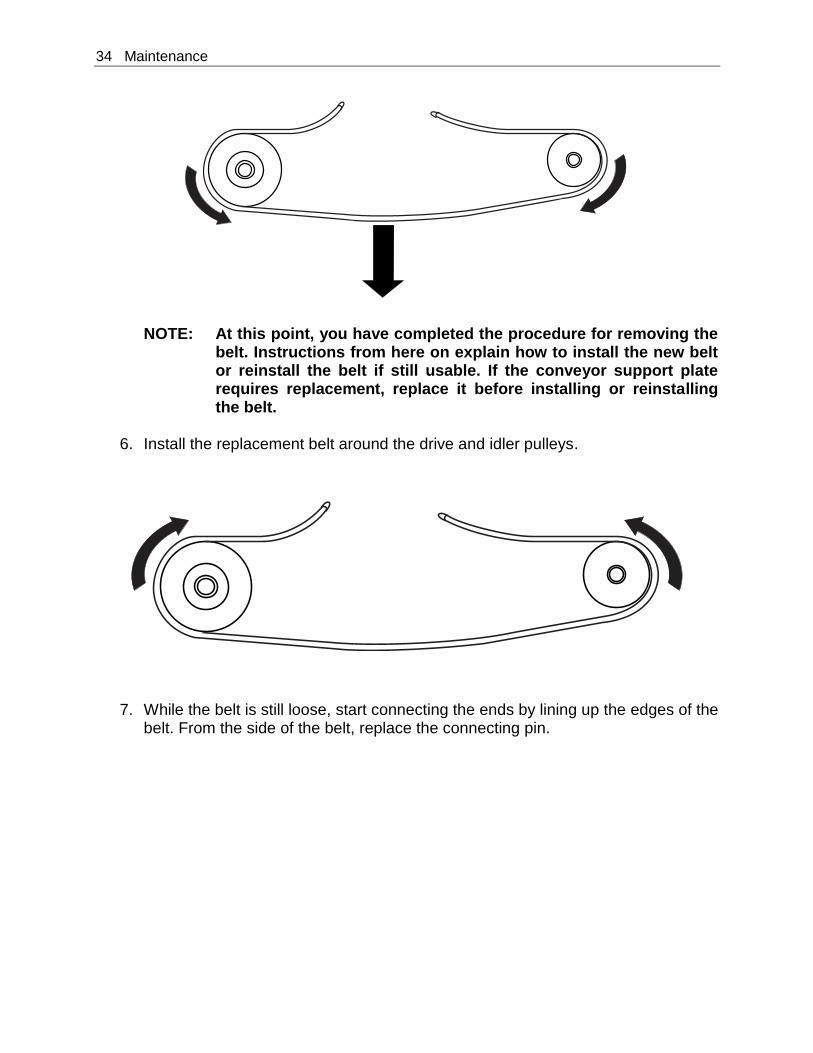
NOTE: At this point, you have completed the procedure for removing the belt. Instructions from here on explain how to install the new belt or reinstall the belt if still usable. If the conveyor support plate requires replacement, replace it before installing or reinstalling the belt.
6. Install the replacement belt around the drive and idler pulleys.
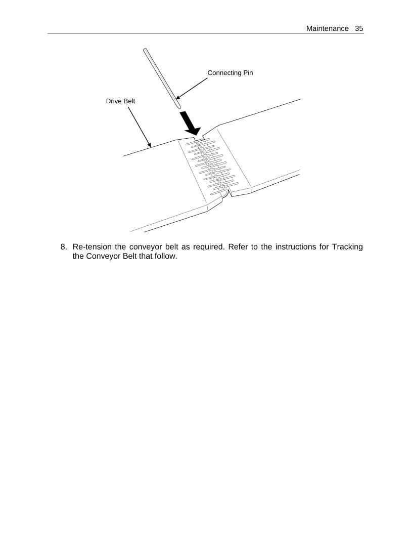
7. While the belt is still loose, start connecting the ends by lining up the edges of the belt. From the side of the belt, replace the connecting pin.
Maintenance 35
8. Re-tension the conveyor belt as required. Refer to the instructions for Tracking the Conveyor Belt that follow.
Connecting Pin
Drive Belt
36 Maintenance
Tracking the Takeaway Conveyor Belt
From time to time or whenever the takeaway conveyor belt has been replaced, it will be necessary to track or align the belt so that it stays in place on the rollers while moving and delivering the product. The procedure is simple, but can be time-consuming.
1. Identify the drive roller and the idler roller. The drive roller is the larger roller. The idler is smaller and has a crown (rounded surface that is higher at the middle and tapers outward to give the idler a slight “barrel” shape).
2. Place the belt on the rollers in the center and tighten each adjustment screw as
evenly as possible.
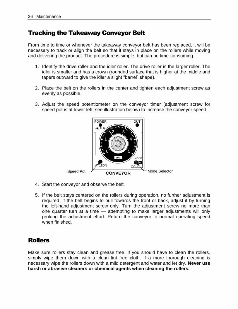
3. Adjust the speed potentiometer on the conveyor timer (adjustment screw for speed pot is at lower left; see illustration below) to increase the conveyor speed.
4. Start the conveyor and observe the belt.
5. If the belt stays centered on the rollers during operation, no further adjustment is required. If the belt begins to pull towards the front or back, adjust it by turning the left-hand adjustment screw only. Turn the adjustment screw no more than one quarter turn at a time — attempting to make larger adjustments will only prolong the adjustment effort. Return the conveyor to normal operating speed when finished.
Rollers
Make sure rollers stay clean and grease free. If you should have to clean the rollers, simply wipe them down with a clean lint free cloth. If a more thorough cleaning is necessary wipe the rollers down with a mild detergent and water and let dry. Never use harsh or abrasive cleaners or chemical agents when cleaning the rollers.
0
1
2 3
4
5
POWER OUT
MODE
AT11DN
RUN
A
CONVEYOR
sec.
Speed Pot Mode Selector

Troubleshooting 37
Troubleshooting
Problem Solution
No Element Heat Check to be sure sealer is plugged in and electrical power is present at the outlet.
Is the display for temperature on? If not, check main fuses.
Is the Out light on when the SV is lower than the PV setting? The temperature controller will read Open.
Is the green light on the solid state relay on when the Out light on the temperature controller is on?
Conveyor Does Not Run
0
1
2 3
4
5
POWER OUT
MODE
AT11DN
RUN
A
CONVEYOR
sec.
With the seal head up the light in the left hand corner of the temperature timer stays lit all the time.
If the light is on, bring the seal head down. The light should start flashing.
Is the timer in “A” mode?
Mode selector is to the lower right corner of the dial.
Inside the conveyor speed dial, is the setting between 0 and 5?
Timer speed pot adjustment is to the lower left corner of the dial.
At the bottom of the speed dial, is “sec” displayed?
Units of time selected is displayed at center near the bottom of the dial.
Is the limit switch on the back of the machine being fully actuated (pressed in)?
Press the limit switch in by hand, and then let it go.
38 Troubleshooting
Problem Solution
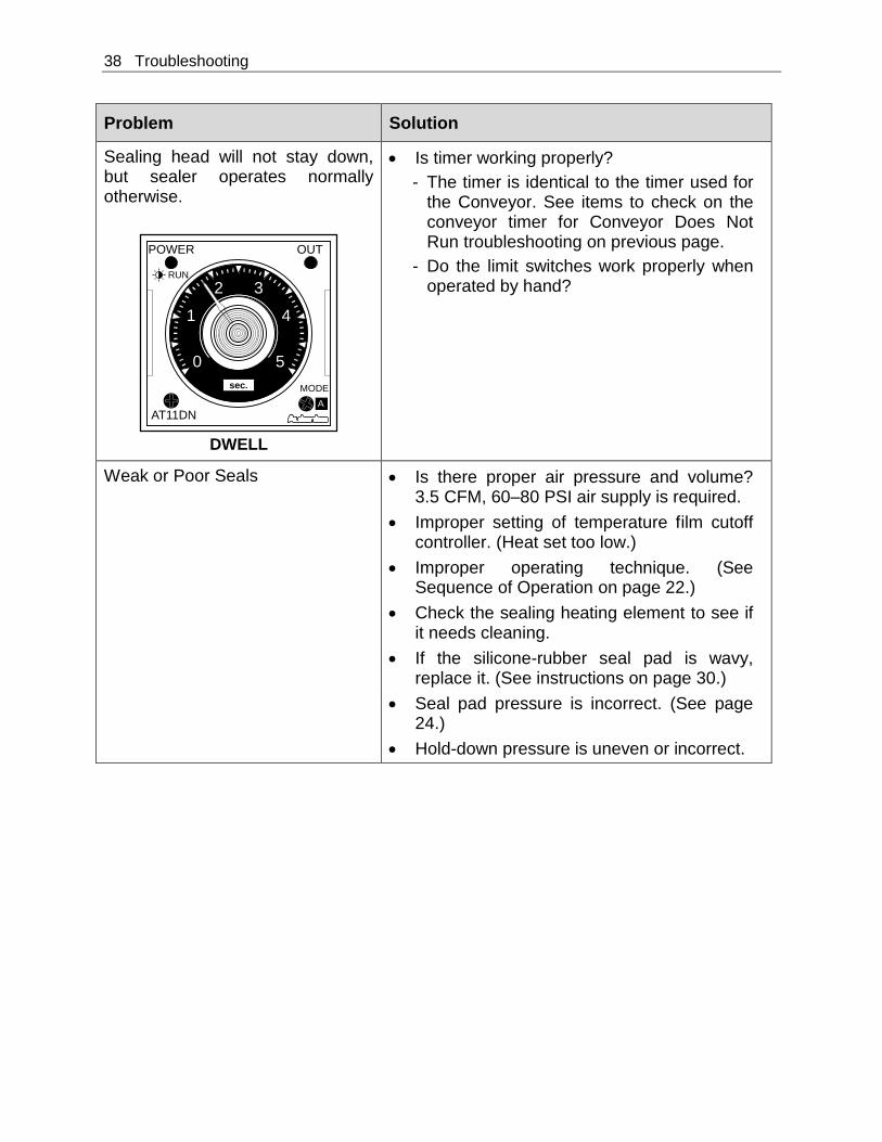
Sealing head will not stay down, but sealer operates normally otherwise.
0
1
2 3
4
5
POWER OUT
MODE
AT11DN
RUN
A
DWELL
sec.
Is timer working properly?
The timer is identical to the timer used for the Conveyor. See items to check on the conveyor timer for Conveyor Does Not Run troubleshooting on previous page.
Do the limit switches work properly when operated by hand?
Weak or Poor Seals Is there proper air pressure and volume? 3.5 CFM, 60–80 PSI air supply is required.
Improper setting of temperature film cutoff controller. (Heat set too low.)
Improper operating technique. (See Sequence of Operation on page 22.)
Check the sealing heating element to see if it needs cleaning.
If the silicone-rubber seal pad is wavy, replace it. (See instructions on page 30.)
Seal pad pressure is incorrect. (See page 24.)
Hold-down pressure is uneven or incorrect.
Troubleshooting 39
Problem
Seal Heads Stay Engaged When They Should Release
Solution
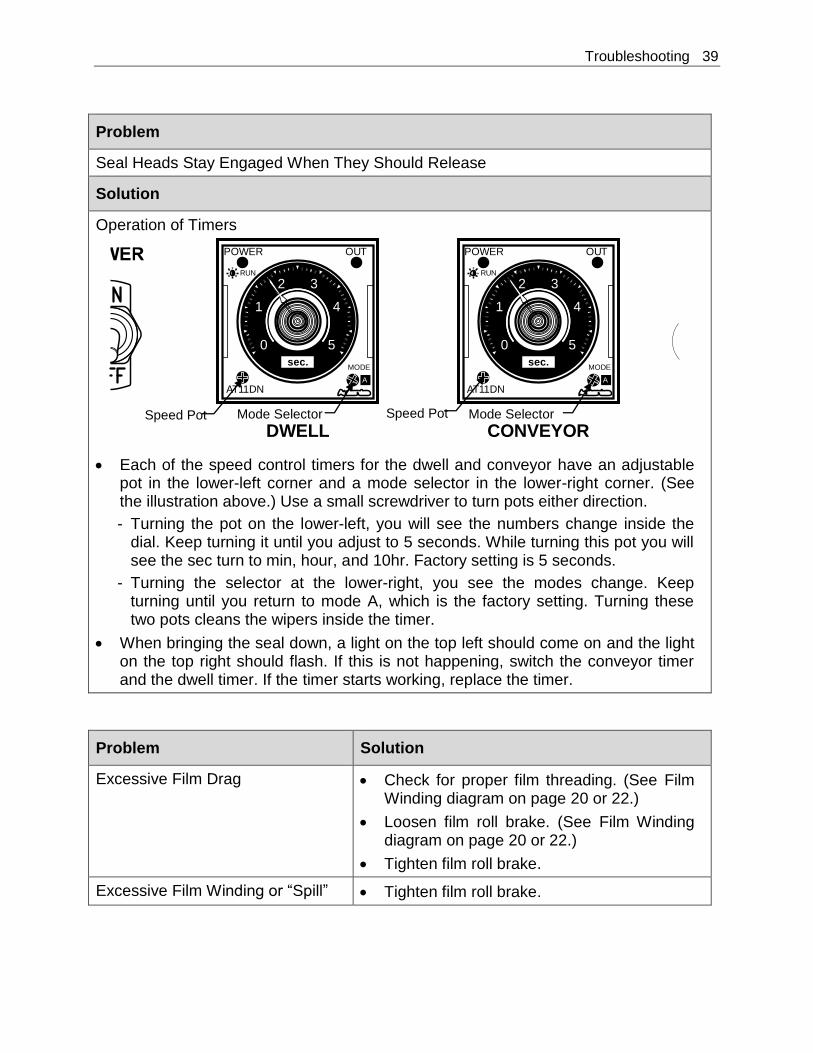
Operation of Timers
Each of the speed control timers for the dwell and conveyor have an adjustable pot in the lower-left corner and a mode selector in the lower-right corner. (See the illustration above.) Use a small screwdriver to turn pots either direction.
Turning the pot on the lower-left, you will see the numbers change inside the dial. Keep turning it until you adjust to 5 seconds. While turning this pot you will see the sec turn to min, hour, and 10hr. Factory setting is 5 seconds.
Turning the selector at the lower-right, you see the modes change. Keep turning until you return to mode A, which is the factory setting. Turning these two pots cleans the wipers inside the timer.
When bringing the seal down, a light on the top left should come on and the light on the top right should flash. If this is not happening, switch the conveyor timer and the dwell timer. If the timer starts working, replace the timer.
Problem Solution
Excessive Film Drag Check for proper film threading. (See Film Winding diagram on page 20 or 22.)
Loosen film roll brake. (See Film Winding diagram on page 20 or 22.)
Tighten film roll brake.
Excessive Film Winding or “Spill” Tighten film roll brake.
0
1
2 3
4
5
POWER OUT
MODE
AT11DN
RUN
A
0
1
2 3
4
5
POWER OUT
MODE
AT11DN
RUN
A
DWELL CONVEYOR
sec. sec.
Speed Pot Mode Selector Speed Pot Mode Selector

40 Troubleshooting
Problem Solution
Charring of Film Improper setting of temperature film cutoff controller. (Too much heat.) Adjust temperature down.

Parts List 41
Parts List
ESA2028-TKV1-SP82
ITEM PART NO. DESCRIPTION Q’TY
1 EAST0490 TEMPERATURE CONTROLLER 2
2 EAST1030 DWELL TIMER 220V 2
3 ETC00309 ON/OFF SWITCH 1
4 EP000517 AIR VALVE 1
5 ESC00515 AIR FILTER/REGULATOR 1
6 5003034 FTG – SLOW START VALVE 1
7 EP000550 PALM BUTTON START 2
8 ESC00604 PALM BUTTON STOP 1
9 EAST0029 LIMIT SWITCH 3
10 EP000592 LATCH 1
11 EP000545 CLAMP STRAIGHT LINE 1
12 ETC00185 MOTOR CONVEYOR DRIVE 1
13 EP000601 AIR CYLINDER 3 × 5 1
14 EAST0035 SWITCH POLY NORMAL 1
15 EP000558 SWITCH TOGGLE, SPST MOVEMENT 1
42 Parts List
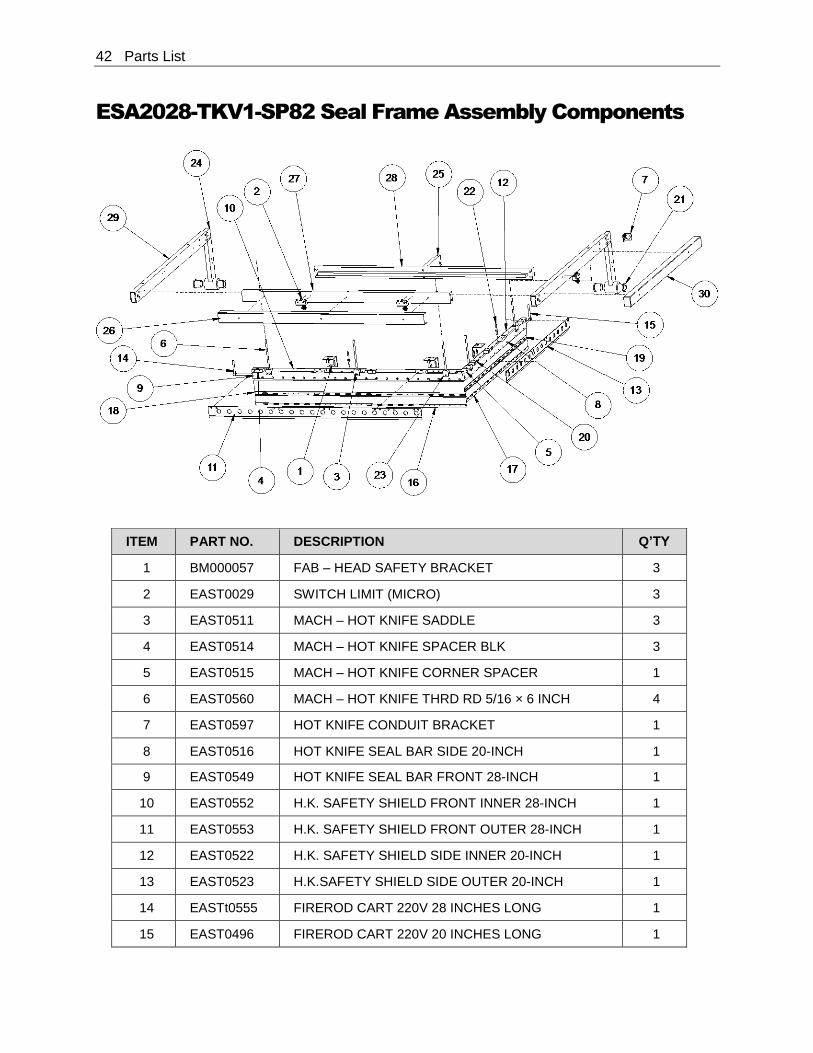
ESA2028-TKV1-SP82 Seal Frame Assembly Components
ITEM PART NO. DESCRIPTION Q’TY
1 BM000057 FAB – HEAD SAFETY BRACKET 3
2 EAST0029 SWITCH LIMIT (MICRO) 3
3 EAST0511 MACH – HOT KNIFE SADDLE 3
4 EAST0514 MACH – HOT KNIFE SPACER BLK 3
5 EAST0515 MACH – HOT KNIFE CORNER SPACER 1
6 EAST0560 MACH – HOT KNIFE THRD RD 5/16 × 6 INCH 4
7 EAST0597 HOT KNIFE CONDUIT BRACKET 1
8 EAST0516 HOT KNIFE SEAL BAR SIDE 20-INCH 1
9 EAST0549 HOT KNIFE SEAL BAR FRONT 28-INCH 1
10 EAST0552 H.K. SAFETY SHIELD FRONT INNER 28-INCH 1
11 EAST0553 H.K. SAFETY SHIELD FRONT OUTER 28-INCH 1
12 EAST0522 H.K. SAFETY SHIELD SIDE INNER 20-INCH 1
13 EAST0523 H.K.SAFETY SHIELD SIDE OUTER 20-INCH 1
14 EASTt0555 FIREROD CART 220V 28 INCHES LONG 1
15 EAST0496 FIREROD CART 220V 20 INCHES LONG 1
Parts List 43
ITEM PART NO. DESCRIPTION Q’TY
16 EAST0817 HOT KNIFE CUTTING RULE FRONT 28 INCH 1
17 EAST0815 HOT KNIFE CUTTING RULE SIDE 20 INCH 1
18 EAST0920 HOT KNIFE MUSHROOM INSERT FRONT 28 INCH 1
19 EAST0918 HOT KNIFE MUSHROOM INSERT SIDE 20 INCH 1
20 EP000095 MACH – HOT KNIFE SPACER BLACK WITH HOLE 3
21 EP000504 BUSHING – FLANGE 1 INCH O.D. × 1-1/4 INCH × 1 4
22 EP000535 THERMOCOUPLE HOT KNIFE 2
23 ESC00037 MACH – HOT KNIFE SADDLE CENTER 1
24 SA000130 W/F – HEAD FRAME, BRACKET 2
25 SA000131 MACH – HEAD AIR CYLINDER ARM 1
26 SA028005 FAB – HOT KNIFE WIRE GUARD FRONT 28 INCH 1
27 SA028050 MACH – HOT KNIFE CROSS OVER BAR 28 INCH 1
28 SA028054 W/F – REAR CROSS OVER BAR 28 INCH 1
29 SA200001 W/F – SEAL HEAD SIDE ARM 20 INCH 2
30 SA200005 FAB – HOT KNIFE WIRE GUARD SIDE 20 INCH 1
44 Parts List
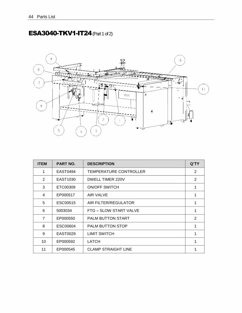
ESA3040-TKV1-IT24 (Part 1 of 2)
ITEM PART NO. DESCRIPTION Q’TY
1 EAST0494 TEMPERATURE CONTROLLER 2
2 EAST1030 DWELL TIMER 220V 2
3 ETC00309 ON/OFF SWITCH 1
4 EP000517 AIR VALVE 1
5 ESC00515 AIR FILTER/REGULATOR 1
6 5003034 FTG – SLOW START VALVE 1
7 EP000550 PALM BUTTON START 2
8 ESC00604 PALM BUTTON STOP 1
9 EAST0029 LIMIT SWITCH 1
10 EP000592 LATCH 1
11 EP000545 CLAMP STRAIGHT LINE 1
Parts List 45
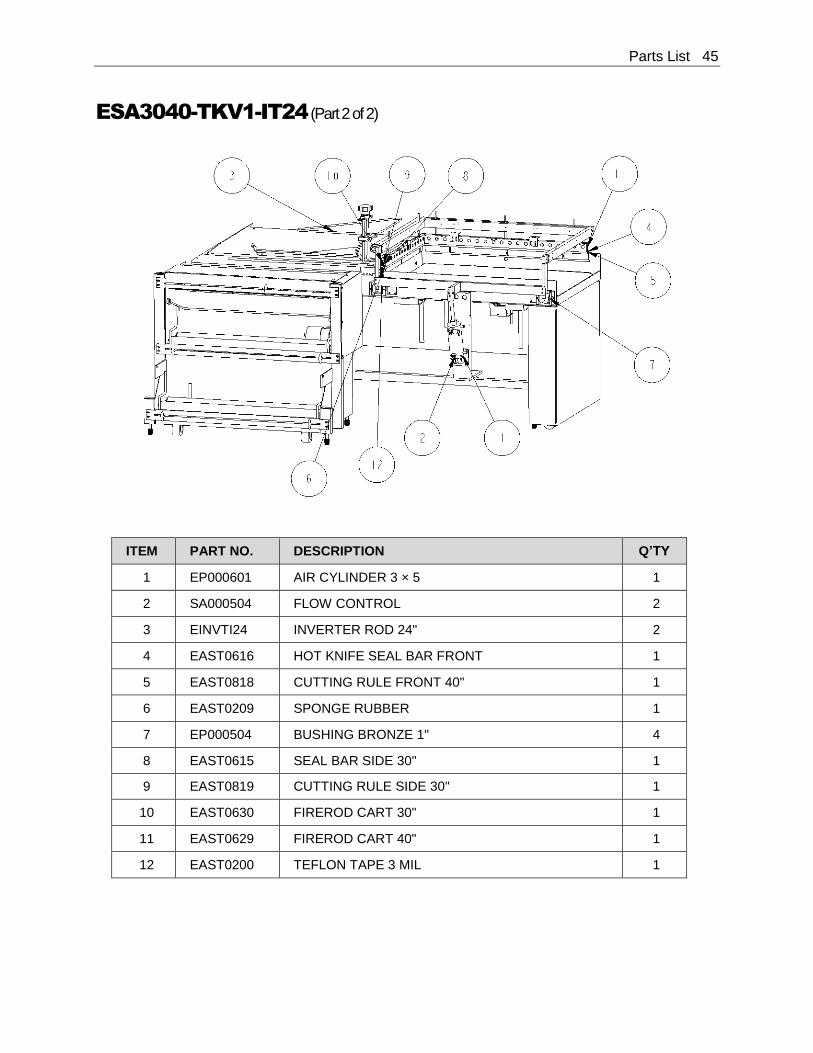
ESA3040-TKV1-IT24 (Part 2 of 2)
ITEM PART NO. DESCRIPTION Q’TY
1 EP000601 AIR CYLINDER 3 × 5 1
2 SA000504 FLOW CONTROL 2
3 EINVTI24 INVERTER ROD 24" 2
4 EAST0616 HOT KNIFE SEAL BAR FRONT 1
5 EAST0818 CUTTING RULE FRONT 40" 1
6 EAST0209 SPONGE RUBBER 1
7 EP000504 BUSHING BRONZE 1" 4
8 EAST0615 SEAL BAR SIDE 30" 1
9 EAST0819 CUTTING RULE SIDE 30" 1
10 EAST0630 FIREROD CART 30" 1
11 EAST0629 FIREROD CART 40" 1
12 EAST0200 TEFLON TAPE 3 MIL 1

46 Parts List
ESA2028-TKV1-IT24 Seal Frame Assembly Components
ITEM PART NO. DESCRIPTION Q’TY
1 BM000057 FAB – HEAD SAFETY BRACKET 3
2 EAST0029 SWITCH LIMIT (MICRO) 3
3 EAST0511 MACH – HOT KNIFE SADDLE 4
4 EAST0514 MACH – HOT KNIFE SPACER BLACK 3
5 EAST0515 MACH – HOT KNIFE CORNER SPACER 1
6 EAST0560 MACH – HOT KNIFE THIRD RD 5/16 INCH × 6 INCH 5
7 EAST0597 HOT KNIFE CONDUIT BRACKET 1
8 EAST0615 HOT KNIFE SEAL BAR SIDE 30 INCH 1
9 EAST0616 HOT KNIFE SEAL BAR FRONT 40 INCH 1
10 EAST0622 H.K. SAFETY SHIELD FRONT INNER 40 INCH 1
11 EAST0623 H.K. SAFETY SHIELD FRONT OUTER 40 INCH 1
12 EAST0624 H.K. SAFETY SHIELD SIDE INNER 30 INCH 1
13 EAST0625 H.K. SAFETY SHIELD SIDE OUTER 30 INCH 1
14 EAST0629 FIREROD CART 220V 40 INCHES LONG 1
15 EAST0630 FIREROD CART 220V 30 INCHES LONG 1
Parts List 47
ITEM PART NO. DESCRIPTION Q’TY
16 EAST0818 HOT KNIFE CUTTING RULE FRONT 40 INCH 1
17 EAST0819 HOT KNIFE CUTTING RULE SIDE 30 INCH 1
18 EAST0916 HOT KNIFE MUSHROOM INSERT FRONT 40 INCH 1
19 EAST0917 HOT KNIFE MUSHROOM INSERT SIDE 30 INCH 1
20 EP000095 MACH – HOT KNIFE SPACER BLACK WITH HOLE 5
21 EP000504 BUSHING FLANGE 1 INCH O.D. × 1-1/4 × 1 4
22 EP000535 THERMOCOUPLE HOT KNIFE 2
23 ESC00037 MACH – HOT KNIFE SADDLE CENTER 1
24 SA000130 W/F – HEAD FRAME, BRACKET 2
25 SA000131 MACH – HEAD AIR CYLINDER ARM 1
26 SA040005 FAB – HOT KNIFE WIRE GUARD FRONT 40 INCH 1
27 SA040050 MACH – HOT KNIFE CROSS OVER BAR 40 INCH 1
28 SA040054 W/F – REAR CROSS OVER BAR 40 INCH 1
29 SA300001 W/F – SEAL HEAD SIDE ARM 30 INCH 2
30 SA300005 FAB – HOT KNIFE WIRE GUARD SIDE 30 INCH 1
48 Parts List
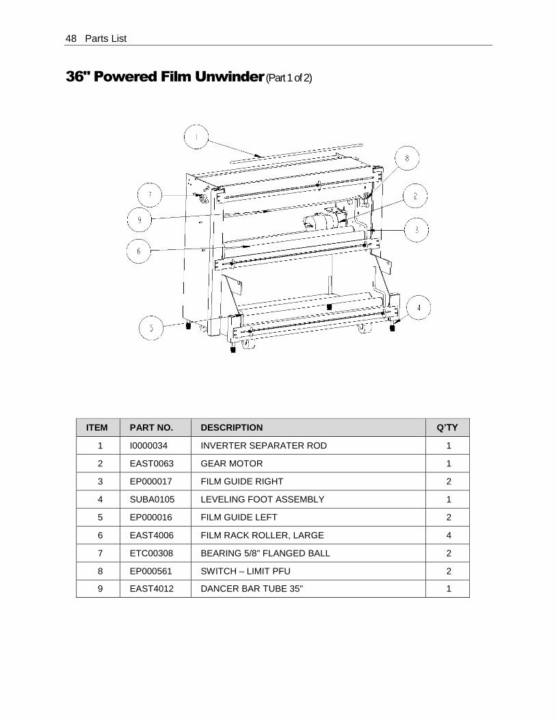
36" Powered Film Unwinder (Part 1 of 2)
ITEM PART NO. DESCRIPTION Q’TY
1 I0000034 INVERTER SEPARATER ROD 1
2 EAST0063 GEAR MOTOR 1
3 EP000017 FILM GUIDE RIGHT 2
4 SUBA0105 LEVELING FOOT ASSEMBLY 1
5 EP000016 FILM GUIDE LEFT 2
6 EAST4006 FILM RACK ROLLER, LARGE 4
7 ETC00308 BEARING 5/8" FLANGED BALL 2
8 EP000561 SWITCH – LIMIT PFU 2
9 EAST4012 DANCER BAR TUBE 35" 1
Parts List 49
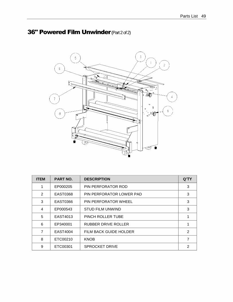
36" Powered Film Unwinder (Part 2 of 2)
ITEM PART NO. DESCRIPTION Q’TY
1 EP000205 PIN PERFORATOR ROD 3
2 EAST0368 PIN PERFORATOR LOWER PAD 3
3 EAST0366 PIN PERFORATOR WHEEL 3
4 EP000543 STUD FILM UNWIND 3
5 EAST4013 PINCH ROLLER TUBE 1
6 EP340001 RUBBER DRIVE ROLLER 1
7 EAST4004 FILM BACK GUIDE HOLDER 2
8 ETC00210 KNOB 7
9 ETC00301 SPROCKET DRIVE 2

50 Parts List
Appendix A: Electrical Schematic 51
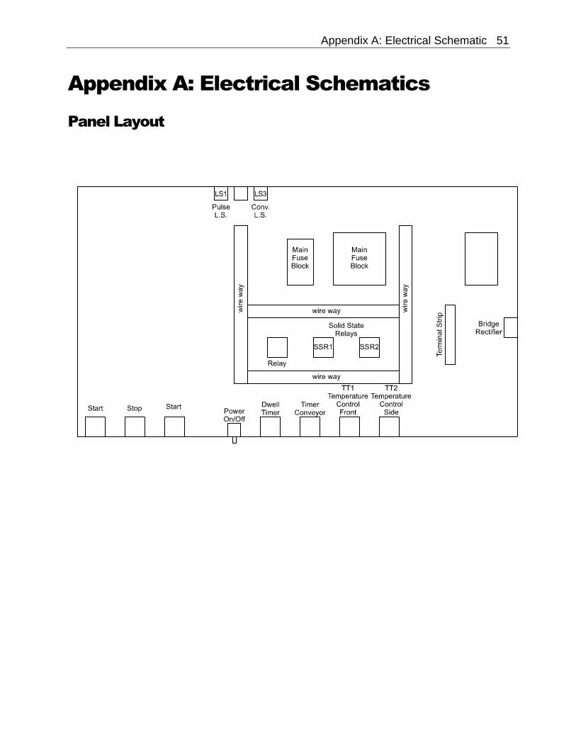
Appendix A: Electrical Schematics
Panel Layout
52 Appendix A: Electrical Schematic
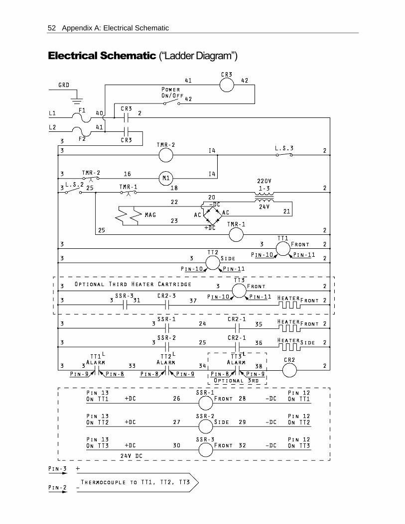
Electrical Schematic (“Ladder Diagram”)
Appendix B: Air Diagram 53
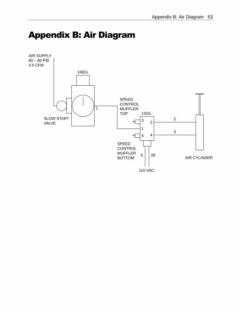
Appendix B: Air Diagram
AIR SUPPLY
60 – 80 PSI
3.5 CFM
SPEED
CONTROL
MUFFLER
TOP
SPEED
CONTROL
MUFFLER
BOTTOM
1REG
110 VAC
AIR CYLINDER
1SOL
SLOW START
VALVE
1
32
4
2
31
5
6 28

54 Appendix C: Temperature Setting Specifications
Appendix C: Temperature Setting
Specifications for Shrink-Wrap Plastics
Mushroom Insert
PVC (Poly-Vinyl Chloride) Temperature settings:
Pad type: Dwell Time:
325° F front bar; 325° F side bar Felt Approximately 1 second
Polyolefin Temperature settings: Pad type: Dwell Time:
335° F front bar; 335° F side bar Sponge rubber Approximately 1 second
Polyethylene Temperature settings: Pad type: Dwell Time:
360° F front bar; 360° F side bar Sponge rubber Approximately 1.5 second
L-Sealer Size Estimating 55
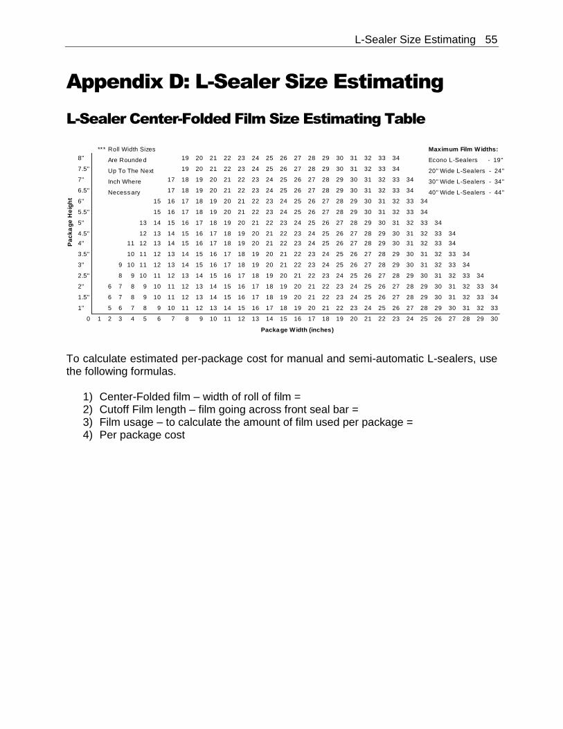
Appendix D: L-Sealer Size Estimating
L-Sealer Center-Folded Film Size Estimating Table
To calculate estimated per-package cost for manual and semi-automatic L-sealers, use the following formulas.
1) Center-Folded film – width of roll of film = 2) Cutoff Film length – film going across front seal bar = 3) Film usage – to calculate the amount of film used per package = 4) Per package cost
*** Roll Width Sizes Maximum Film Widths:
8" Are Rounde d 19 20 21 22 23 24 25 26 27 28 29 30 31 32 33 34 Econo L-Sealers - 19"
7.5" Up To The Next 19 20 21 22 23 24 25 26 27 28 29 30 31 32 33 34 20" Wide L-Sealers - 24"
7" Inch Where 17 18 19 20 21 22 23 24 25 26 27 28 29 30 31 32 33 34 30" Wide L-Sealers - 34"
6.5" Necess ary 17 18 19 20 21 22 23 24 25 26 27 28 29 30 31 32 33 34 40" Wide L-Sealers - 44"
6" 15 16 17 18 19 20 21 22 23 24 25 26 27 28 29 30 31 32 33 34
5.5" 15 16 17 18 19 20 21 22 23 24 25 26 27 28 29 30 31 32 33 34
5" 13 14 15 16 17 18 19 20 21 22 23 24 25 26 27 28 29 30 31 32 33 34
4.5" 12 13 14 15 16 17 18 19 20 21 22 23 24 25 26 27 28 29 30 31 32 33 34
4" 11 12 13 14 15 16 17 18 19 20 21 22 23 24 25 26 27 28 29 30 31 32 33 34
3.5" 10 11 12 13 14 15 16 17 18 19 20 21 22 23 24 25 26 27 28 29 30 31 32 33 34
3" 9 10 11 12 13 14 15 16 17 18 19 20 21 22 23 24 25 26 27 28 29 30 31 32 33 34
2.5" 8 9 10 11 12 13 14 15 16 17 18 19 20 21 22 23 24 25 26 27 28 29 30 31 32 33 34
2" 6 7 8 9 10 11 12 13 14 15 16 17 18 19 20 21 22 23 24 25 26 27 28 29 30 31 32 33 34
1.5" 6 7 8 9 10 11 12 13 14 15 16 17 18 19 20 21 22 23 24 25 26 27 28 29 30 31 32 33 34
1" 5 6 7 8 9 10 11 12 13 14 15 16 17 18 19 20 21 22 23 24 25 26 27 28 29 30 31 32 33
0 1 2 3 4 5 6 7 8 9 10 11 12 13 14 15 16 17 18 19 20 21 22 23 24 25 26 27 28 29 30
Package Width (inches)
Pa
ck
ag
eH
eig
ht
56 L-Sealer Size Estimating
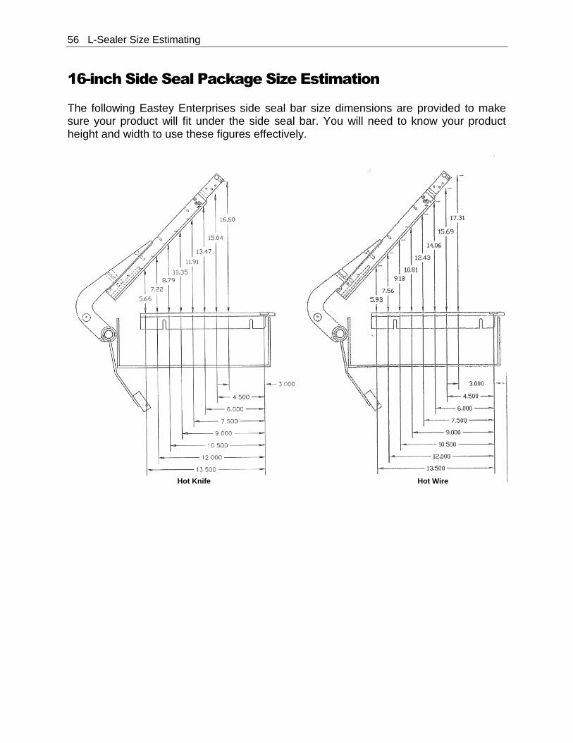
16-inch Side Seal Package Size Estimation
The following Eastey Enterprises side seal bar size dimensions are provided to make sure your product will fit under the side seal bar. You will need to know your product height and width to use these figures effectively.
Hot Knife Hot Wire
L-Sealer Size Estimating 57
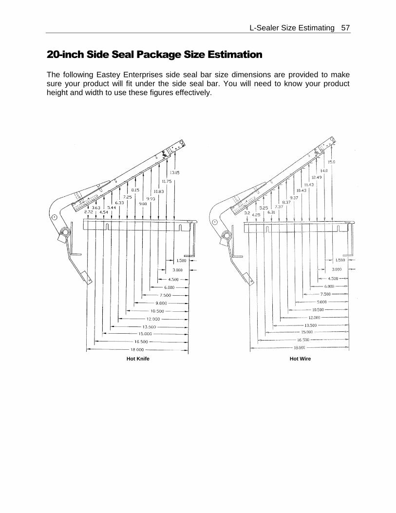
20-inch Side Seal Package Size Estimation
The following Eastey Enterprises side seal bar size dimensions are provided to make sure your product will fit under the side seal bar. You will need to know your product height and width to use these figures effectively.
Hot Knife Hot Wire
58 L-Sealer Size Estimating
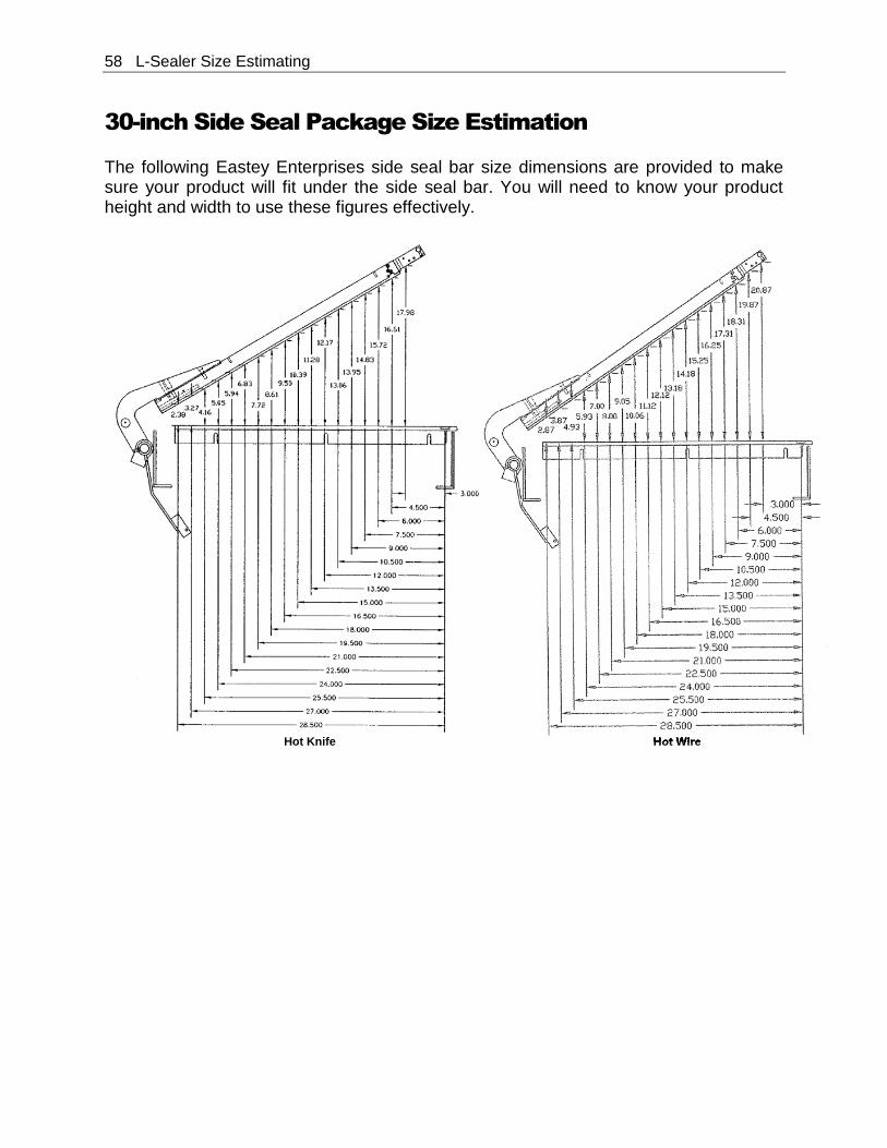
30-inch Side Seal Package Size Estimation
The following Eastey Enterprises side seal bar size dimensions are provided to make sure your product will fit under the side seal bar. You will need to know your product height and width to use these figures effectively.
Hot Knife Hot Wire

L-Sealer Size Estimating 59
40-inch Side Seal Package Size Estimation
The following Eastey Enterprises side seal bar size dimensions are provided to make sure your product will fit under the side seal bar. You will need to know your product height and width to use these figures effectively.
60 Warranty Statement
Warranty Statement
ESA Professional Series Semi-Automatic L-Sealers
Warranty Statement Eastey Enterprises warrants that all of the products it ships will be in good working order and free from defects in material and workmanship for a period of two (2) years from the date of shipment by Eastey and will conform to the published specifications for that product. Spare parts that are manufactured in house by Eastey will be warranted for two (2) years. Bought out parts will be warranted for one (1) year. Warranty Period – Specific Items
Drive motor(s): 1 year Gear reducer: 1 year Termination Post 30 days Conveyor Belt 30 days Hole Punches 30 days (ball and die) Knurled Nut 30 days The following parts are considered to be consumable items and not under warranty: fuses, ¼ " × ¾ " sponge rubber, copper heat sinks, 036 Nichrome wire, ¾ " Teflon tape, and ½ " Teflon tape. All other parts: 1 year (Except for moving parts which are subject to normal
wear, tear and replacement which are warranted to be free from defects in material and workmanship.)
Sealing Quality Sealing quality achieved in a given application is dependent on the installation, the material handling, and the maintenance provided. Eastey makes no warranty that the sealing quality achieved in an application will be the same as that achieved on a test piece in our demo facility. Shipping Policy Customer pays all incoming shipping. If the item is defective and under warranty, Eastey pays return shipping charges for least costly method. If expedited shipping is desired, customer must furnish his shipping account and shipping fees will be charged to that account. Warranty Verification If you conclude that a product may be defective and may be covered by warranty, obtain a Return Material Authorization number by calling our technical support number (toll free at 1-800-835-9344, or 763-428-4846 or Fax: 763-795-8867) or e-mail: [email protected]. Based on the recommendation from Eastey technical support, replacement components may be shipped out via UPS Ground or similar method. If expedited shipping is desired, customer must furnish their shipping account and shipping fees will be charged to that account. Customer is required to return the
Warranty Statement 61
defective component to Eastey. If, after 30 days, Eastey hasn’t received the defective component, the customer will be invoiced for the replacement component. If the returned component is found to not be elegible for warranty, Easty will contact the customer and the customer will be invoiced for the replacement component. Warranty Eligibility The warranty provided by Eastey Enterprises, Inc. is only to the original buyer. Limited Warranty THE ABOVE WARRANTY IS EXCLUSIVE AND IN LIEU OF ALL OTHER WARRANTIES, WHETHER EXPRESSED OR IMPLIED, INCLUDING THE IMPLIED WARRANTIES OF MERCHANTABILITY, FITNESS FOR A PARTICULAR PURPOSE AND NONINFRINGEMENT. Disclaimer of Damages REGARDLESS OF WHETHER ANY REMEDY SET FORTH HEREIN FAILS OF ITS ESSENTIAL PURPOSE, IN NO EVENT WILL EASTEY ENTERPRISES, INC. BE LIABLE FOR ANY SPECIAL, CONSEQUENTIAL, INDIRECT OR SIMILAR DAMAGES, INCLUDING LOST PROFIT OR LOST OPPORTUNITIES OF ANY TYPE ARISING OUT OF THE USE OR INABILITY TO USE THESE PRODUCTS EVEN IF EASTEY ENTERPRISES, INC. HAS BEEN ADVISED OF THE POSSIBILITY OF SUCH DAMAGES.
62 Customer Support
Customer Support
Eastey Technical Service
For help setting up or operating the ESA Professional Series L-Sealer, please contact Eastey Technical Service at one of the numbers listed below. Toll-Free Phone 800-835-9344 Phone 763-428-4846 Fax 763-795-8867 E-mail [email protected] Web www.eastey.com Thank you again for your purchase of Eastey products. We are pleased to be a part of your packaging needs.