Embed Size (px)
Citation preview
GE Hitachi Nuclear Energy
26A6642AR Revision 10
April 2014
ESBWR Design Control Document Tier 2 Chapter 5 Reactor Coolant System and Connected Systems
Copyright 2005, 2014, GE-Hitachi Nuclear Energy Americas LLC
All Rights Reserved
26A6642AR Rev. 10 ESBWR Design Control Document/Tier 2
Contents
5-i
5. Reactor Coolant System and Connected Systems ................................................................ 5.1-1
5.1 Summary Description ......................................................................................................... 5.1-1 5.1.1 Schematic Flow Diagrams ........................................................................................... 5.1-3 5.1.2 Piping and Instrumentation Schematics ....................................................................... 5.1-3 5.1.3 Elevation Schematics ................................................................................................... 5.1-3 5.1.4 COL Information ......................................................................................................... 5.1-3 5.1.5 References .................................................................................................................... 5.1-3
5.2 Integrity of Reactor Coolant Pressure Boundary ................................................................ 5.2-1 5.2.1 Compliance with Codes and Code Cases .................................................................... 5.2-1
5.2.1.1 Compliance with 10 CFR 50.55a .......................................................................... 5.2-1 5.2.1.2 Applicable Code Cases ......................................................................................... 5.2-1
5.2.2 Overpressure Protection ............................................................................................... 5.2-2 5.2.2.1 Design Basis .......................................................................................................... 5.2-4 5.2.2.2 System Description ............................................................................................... 5.2-5 5.2.2.3 Safety Evaluation .................................................................................................. 5.2-8 5.2.2.4 Testing and Inspection Requirements ................................................................... 5.2-8 5.2.2.5 Instrumentation Requirements .............................................................................. 5.2-9
5.2.3 Reactor Coolant Pressure Boundary Materials ............................................................ 5.2-9 5.2.3.1 Material Specifications ....................................................................................... 5.2-10 5.2.3.2 Compatibility with Reactor Coolant ................................................................... 5.2-10 5.2.3.3 Fabrication and Processing of Ferritic Materials ................................................ 5.2-16 5.2.3.4 Fabrication and Processing of Austenitic Stainless Steels .................................. 5.2-18
5.2.4 Preservice and In-service Inspection and Testing of Reactor Coolant Pressure Boundary ............................................................................................................................. 5.2-20
5.2.4.1 Class 1 System Boundary ................................................................................... 5.2-21 5.2.4.2 Accessibility ........................................................................................................ 5.2-22 5.2.4.3 Examination Categories and Methods ................................................................ 5.2-24 5.2.4.4 Inspection Intervals ............................................................................................. 5.2-26 5.2.4.5 Evaluation of Examination Results ..................................................................... 5.2-27 5.2.4.6 System Leakage and Hydrostatic Pressure Tests ................................................ 5.2-27 5.2.4.7 Code Exemptions ................................................................................................ 5.2-27 5.2.4.8 Code Cases .......................................................................................................... 5.2-28 5.2.4.9 Preservice Examination....................................................................................... 5.2-28 5.2.4.10 Relief Requests ................................................................................................. 5.2-28 5.2.4.11 COL Information for Preservice and In-service Inspection and Testing of Reactor Coolant Pressure Boundary ............................................................................... 5.2-28
5.2.5 Reactor Coolant Pressure Boundary Leakage Detection ........................................... 5.2-29 5.2.5.1 Leakage Detection Methods ............................................................................... 5.2-31 5.2.5.2 Leak Detection Instrumentation and Monitoring ................................................ 5.2-32 5.2.5.3 Display and Indications in the Main Control Room ........................................... 5.2-37 5.2.5.4 Limits for Reactor Coolant Leakage Rates Within the Drywell ......................... 5.2-37 5.2.5.5 Criteria to Evaluate the Adequacy and Margin of Leak Detection System ........ 5.2-37 5.2.5.6 Separation of Identified and Unidentified Leakages in the Containment ........... 5.2-38
26A6642AR Rev. 10 ESBWR Design Control Document/Tier 2
Contents
5-ii
5.2.5.7 Testing, Calibration and Inspection Requirements ............................................. 5.2-38 5.2.5.8 Regulatory Guide 1.45 Compliance .................................................................... 5.2-38 5.2.5.9 COL Information for Leak Detection Monitoring .............................................. 5.2-39
5.2.6 COL Information ....................................................................................................... 5.2-39 5.2.7 References .................................................................................................................. 5.2-40
5.3 Reactor Vessel .................................................................................................................... 5.3-1 5.3.1 Reactor Vessel Materials ............................................................................................. 5.3-1
5.3.1.1 Materials Specifications ........................................................................................ 5.3-1 5.3.1.2 Special Procedures Used for Manufacturing and Fabrication .............................. 5.3-1 5.3.1.3 Special Methods for Nondestructive Examination ............................................... 5.3-2 5.3.1.4 Special Controls for Ferritic and Austenitic Stainless Steels ................................ 5.3-3 5.3.1.5 Fracture Toughness ............................................................................................... 5.3-4 5.3.1.6 Material Surveillance ............................................................................................ 5.3-5 5.3.1.7 Reactor Vessel Fasteners ...................................................................................... 5.3-7 5.3.1.8 COL Information for Reactor Vessel Material Surveillance Program ................. 5.3-8
5.3.2 Pressure/Temperature Limits ....................................................................................... 5.3-8 5.3.2.1 Limit Curves ......................................................................................................... 5.3-9 5.3.2.2 Operating Procedures .......................................................................................... 5.3-11
5.3.3 Reactor Vessel Integrity ............................................................................................. 5.3-11 5.3.3.1 Design Bases ....................................................................................................... 5.3-13 5.3.3.2 Description .......................................................................................................... 5.3-14 5.3.3.3 Materials of Construction ................................................................................... 5.3-17 5.3.3.4 Inspection Requirements ..................................................................................... 5.3-17 5.3.3.5 Shipment and Installation ................................................................................... 5.3-18 5.3.3.6 Operating Conditions .......................................................................................... 5.3-18 5.3.3.7 In-service Surveillance ........................................................................................ 5.3-18
5.3.4 COL Information ....................................................................................................... 5.3-19 5.3.5 References .................................................................................................................. 5.3-19
5.4 Component and Subsystem Design .................................................................................... 5.4-1 5.4.1 Reactor Recirculation System ...................................................................................... 5.4-1
5.4.1.1 Pump Flywheel Integrity (PWR) .......................................................................... 5.4-1 5.4.2 Steam Generators (PWR) ............................................................................................. 5.4-1
5.4.2.1 Steam Generator Materials.................................................................................... 5.4-1 5.4.2.2 Steam Generator Tube In-service Inspection ........................................................ 5.4-1
5.4.3 Reactor Coolant Piping ................................................................................................ 5.4-1 5.4.4 Main Steamline Flow Restrictors ................................................................................ 5.4-1
5.4.4.1 Safety Design Bases .............................................................................................. 5.4-1 5.4.4.2 Description ............................................................................................................ 5.4-1 5.4.4.3 Safety Evaluation .................................................................................................. 5.4-2 5.4.4.4 Inspection and Testing .......................................................................................... 5.4-2 5.4.4.5 Instrumentation Requirements .............................................................................. 5.4-2
5.4.5 Nuclear Boiler System Isolation .................................................................................. 5.4-3 5.4.5.1 Design Bases ......................................................................................................... 5.4-3
26A6642AR Rev. 10 ESBWR Design Control Document/Tier 2
Contents
5-iii
5.4.5.2 Main Steamlines Isolation ..................................................................................... 5.4-4 5.4.5.3 Feedwater Lines Isolation ..................................................................................... 5.4-6 5.4.5.4 Safety Evaluation .................................................................................................. 5.4-8 5.4.5.5 Testing and Inspection Requirements ................................................................... 5.4-9 5.4.5.6 Instrumentation Requirements ............................................................................ 5.4-10
5.4.6 Isolation Condenser System ....................................................................................... 5.4-10 5.4.6.1 Design Bases ....................................................................................................... 5.4-11 5.4.6.2 System Description ............................................................................................. 5.4-12 5.4.6.3 Safety Evaluation ................................................................................................ 5.4-18 5.4.6.4 Testing and Inspection Requirements ................................................................. 5.4-19 5.4.6.5 Instrumentation Requirements ............................................................................ 5.4-20
5.4.7 Residual Heat Removal System ................................................................................. 5.4-21 5.4.8 Reactor Water Cleanup/Shutdown Cooling System .................................................. 5.4-22
5.4.8.1 Reactor Water Cleanup Function .................................................................... 5.4-22 5.4.8.2 Shutdown Cooling Function ........................................................................... 5.4-30
5.4.9 Main Steamlines, Steam Stub Lines, and Feedwater Piping ..................................... 5.4-35 5.4.9.1 Design Bases ....................................................................................................... 5.4-35 5.4.9.2 Description .......................................................................................................... 5.4-35 5.4.9.3 Safety Evaluation ................................................................................................ 5.4-37 5.4.9.4 Testing and Inspection Requirements ................................................................. 5.4-37 5.4.9.5 Instrumentation Requirements ............................................................................ 5.4-37
5.4.10 Pressurizer ................................................................................................................ 5.4-37 5.4.11 Pressurizer Relief Discharge System ....................................................................... 5.4-37 5.4.12 Reactor Coolant System High Point Vents .............................................................. 5.4-37
5.4.12.1 Operation of RPV Head Vent System .............................................................. 5.4-39 5.4.12.2 Safety Evaluation .............................................................................................. 5.4-39 5.4.12.3 Inspection and Testing Requirements ............................................................... 5.4-40
5.4.13 Safety and Relief Valves and Depressurization Valves ........................................... 5.4-40 5.4.13.1 Design Bases ..................................................................................................... 5.4-40 5.4.13.2 Description ........................................................................................................ 5.4-40 5.4.13.3 Safety Evaluation .............................................................................................. 5.4-42 5.4.13.4 Testing and Inspection Requirements ............................................................... 5.4-42 5.4.13.5 Instrumentation Requirements .......................................................................... 5.4-43
5.4.14 Component Supports ................................................................................................ 5.4-43 5.4.14.1 Safety Design Bases .......................................................................................... 5.4-43 5.4.14.2 Description ........................................................................................................ 5.4-44 5.4.14.3 Safety Evaluation .............................................................................................. 5.4-44 5.4.14.4 Testing and Inspection Requirements ............................................................... 5.4-44 5.4.14.5 Instrumentation Requirements .......................................................................... 5.4-44
5.4.15 COL Information ..................................................................................................... 5.4-44 5.4.16 References ................................................................................................................ 5.4-44
26A6642AR Rev. 10 ESBWR Design Control Document/Tier 2
5-iv
List of Tables Table 5.2-1 Reactor Coolant Pressure Boundary Components (Applicable Code Cases) .... 5.2-41 Table 5.2-2 Safety Relief Valve and Depressurization Valve Settings and/or Capacities .... 5.2-44 Table 5.2-3 (Deleted) ............................................................................................................. 5.2-45 Table 5.2-4 Reactor Coolant Pressure Boundary Materials ................................................... 5.2-46 Table 5.2-5 Expected ESBWR Water Chemistry .................................................................. 5.2-55 Table 5.2-6 LD&IS Control and Isolation Functions vs. Monitored Variables ..................... 5.2-56 Table 5.2-7 Leakage Sources vs. Monitored Variables .......................................................... 5.2-59 Table 5.3-1 Reactor Vessel Controls ..................................................................................... 5.3-20 Table 5.3-2 Predicted Irradiation Effects on Beltline Materials ............................................ 5.3-22 Table 5.3-3 Reactor Pressure Vessel Dimensions ................................................................. 5.3-23 Table 5.3-4 RPV Fluence Analysis Results ........................................................................... 5.3-24 Table 5.4-1 Component and Subsystem Design Controls ..................................................... 5.4-45 Table 5.4-2 (Deleted) ............................................................................................................. 5.4-50 Table 5.4-3 Reactor Water Cleanup/Shutdown Cooling System Data .................................. 5.4-51 Table 5.4-4 DPV Design and Performance Parameters ......................................................... 5.4-53
26A6642AR Rev. 10 ESBWR Design Control Document/Tier 2
5-v
List of Illustrations Figure 5.1-1. Coolant Volumes ................................................................................................ 5.1-4 Figure 5.1-2. Nuclear Boiler System Schematic ...................................................................... 5.1-5 Figure 5.1-3. Isolation Condenser System Schematic ............................................................. 5.1-6 Figure 5.1-4. Reactor Water Cleanup/Shutdown Cooling System Schematic......................... 5.1-7 Figure 5.2-1. Safety Relief Valve Schematic Elevation ........................................................ 5.2-63 Figure 5.2-2. Safety Relief Valves, Safety Valves, and Depressurization Valves on
Steamlines Diagram .................................................................................................... 5.2-64 Figure 5.2-3. Safety Relief Valve Discharge Line Quencher Arrangement .......................... 5.2-65 Figure 5.3-1. Minimum Temperatures Required Versus Reactor Pressure for
Hydrotest-Core Not Critical (Representative Curve for the ESBWR) ....................... 5.3-25 Figure 5.3-2. Minimum Temperatures Required Versus Reactor Pressure for Normal
Startup and Shutdown (Representative Curve for the ESBWR) ................................ 5.3-26 Figure 5.3-3. Reactor Pressure Vessel System Key Features ................................................ 5.3-27 Figure 5.4-1. Main Steamline Nozzle and Flow Restrictor ................................................... 5.4-54 Figure 5.4-2. (Deleted) ........................................................................................................... 5.4-55 Figure 5.4-3. Layout of Main Steam and Feedwater Lines ................................................... 5.4-56 Figure 5.4-4a. Schematic of the Isolation Condenser ............................................................ 5.4-57 Figure 5.4-4b. Isolation Condenser System Simplified Process Diagram ............................. 5.4-58 Figure 5.4-4c. ICS Simplified Process Diagram – Operating Mode Parameters ................... 5.4-59 Figure 5.4-5. NBS Depressurization Valve ........................................................................... 5.4-60
26A6642AR Rev. 10 ESBWR Design Control Document/Tier 2
5.1-1
5. REACTOR COOLANT SYSTEM AND CONNECTED SYSTEMS
5.1 SUMMARY DESCRIPTION
The Reactor Coolant System (RCS) includes those systems and components that contain or transport fluids coming from or going to the reactor core. These systems form a major portion of the Reactor Coolant Pressure Boundary (RCPB). This chapter provides information regarding the RCS and pressure-containing appendages out to and including isolation valving. This grouping of components is defined as the RCPB.
The RCPB includes all pressure-retaining components such as pressure vessels, piping, pumps, and valves, which are:
• Part of the RCS, or
• Connected to the RCS up to and including any and all of the following:
− The outermost containment isolation valve in piping that penetrates containment;
− The second of the two valves normally closed during normal reactor operation in system piping that does not penetrate containment; and
− The RCS Safety Relief Valve (SRV) piping and the depressurization valve (DPV) piping.
This chapter also deals with various subsystems to the RCPB that are closely allied to it. Specifically, Section 5.4 describes these subsystems.
The Nuclear Boiler System (NBS) pressure relief system protects the RCPB from damage due to overpressure. Protection of the RCPB from overpressure is provided by two methods. The Isolation Condenser System (ICS) that is described in Subsection 5.4.6 is the primary method for limiting NBS pressure increase events. The performance of the ICS to limit NBS pressurization in response to anticipated operating occurrence events is evaluated in Chapter 15. As an alternate method, ten (10) pressure-operated, dual-function SRVs are provided that discharge steam from the NBS to the suppression pool. Detailed evaluation of RCPB overpressure protection and description of the SRVs is provided in Section 5.2. Additionally, eight (8) safety valves, that discharge to the drywell, are provided to supplement the capacity of the SRVs for events of a severity beyond those transients for which the ICS provides pressure-limiting effect (refer to Subsection 15.5.4).
The SRVs can also be automatically actuated to depressurize the NBS in the event of a loss-of-coolant-accident (LOCA) in which the feedwater system, isolation condenser and Control Rod Drive (CRD) system high pressure makeup fail to maintain reactor vessel water level. Depressurization of the NBS by actuation of the DPVs allows the Gravity-Driven Cooling System (GDCS) to supply cooling water to adequately cool the fuel. The Automatic Depressurization System (ADS) that activates the SRVs in relief-mode, and the DPVs, is discussed in Section 6.3.
Subsection 5.2.5 establishes the limits on RCPB leakage inside the drywell so that appropriate action can be taken before the integrity of the RCPB process barrier is impaired.
26A6642AR Rev. 10 ESBWR Design Control Document/Tier 2
5.1-2
The reactor vessel and appurtenances are described in Section 5.3. The major safety consideration for the reactor vessel is the ability of the vessel to function as a radioactive material barrier. Various combinations of loading are considered in the vessel design. The vessel meets the requirements of applicable codes and criteria. The possibility of brittle fracture is considered, and suitable design, material selection, material surveillance activity, and operational limits are established that avoid conditions where brittle fracture is possible.
The RCS provides coolant flow through the core by natural circulation within the reactor vessel. The core coolant flow rate changes with reactor power output. The control rods are adjusted either manually or automatically with the Fine Motion Control Rod Drives to adjust reactor power. The natural recirculation within the reactor vessel eliminates the need for a forced-flow pump-driven recirculation system. Therefore there are no large piping connections to the reactor vessel below the core and there are no recirculation pumps. The thermal-hydraulic design for reactor core coolant flow by natural recirculation is discussed in Section 4.4.
Main steamline flow restrictors of the venturi-type are part of the main steam nozzle on the reactor pressure vessel. The restrictors are designed to limit the loss of coolant resulting from a main steamline break inside or outside the containment. The restrictors limit the reactor depressurization rate to a value that ensures the steam dryer and other reactor internal structures remain in place and limit the radiological release outside of containment before closure of the Main Steam Isolation Valves (MSIVs).
Two isolation valves are installed on each main steamline. One is located inside the containment and the other is located outside the containment. If a main steamline break occurs inside the containment, closure of the isolation valve outside the containment seals the containment itself. The MSIVs automatically isolate the RCPB when a pipe break occurs outside containment. This action limits the loss of reactor coolant and the release of radioactive materials.
The CRD system provides makeup water via the Reactor Water Cleanup/Shutdown Cooling (RWCU/SDC) system piping to the core anytime feedwater flow is not available. The system is started automatically upon receipt of a Level 2 reactor water level signal or manually by the operator. The CRD system is discussed in Section 4.6.
The RWCU/SDC and the ICS can be used to cool the RCS under a variety of situations. During normal shutdown and reactor servicing, the RWCU/SDC removes residual and decay heat. The RWCU/SDC in conjunction with the ICS allows decay heat to be removed whenever the main heat sink (main condenser) is not available (e.g., hot standby). The ICS provides cooling of the reactor if the RCPB becomes isolated following a scram during power operations. The ICS automatically removes residual sensible and core decay heat to limit reactor pressure when reactor isolation occurs. Over a longer duration, the ICS provides a way to remove excess heat from the reactor with minimal loss of coolant inventory, if the normal heat removal path is unavailable.
The GDCS is an engineered safety feature system for use during a postulated LOCA. The GDCS is operational at low reactor vessel pressure following pressure reduction by the ADS Operation of the GDCS and ADS is described in Section 6.3.
The RWCU/SDC recirculates a portion of reactor coolant through a demineralizer to remove dissolved impurities with their associated corrosion and fission products from the reactor coolant. It also removes excess coolant from the reactor system under controlled conditions.
26A6642AR Rev. 10 ESBWR Design Control Document/Tier 2
5.1-3
5.1.1 Schematic Flow Diagrams
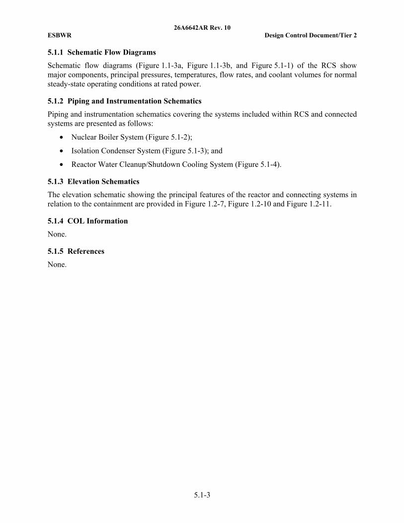
Schematic flow diagrams (Figure 1.1-3a, Figure 1.1-3b, and Figure 5.1-1) of the RCS show major components, principal pressures, temperatures, flow rates, and coolant volumes for normal steady-state operating conditions at rated power.
5.1.2 Piping and Instrumentation Schematics
Piping and instrumentation schematics covering the systems included within RCS and connected systems are presented as follows:
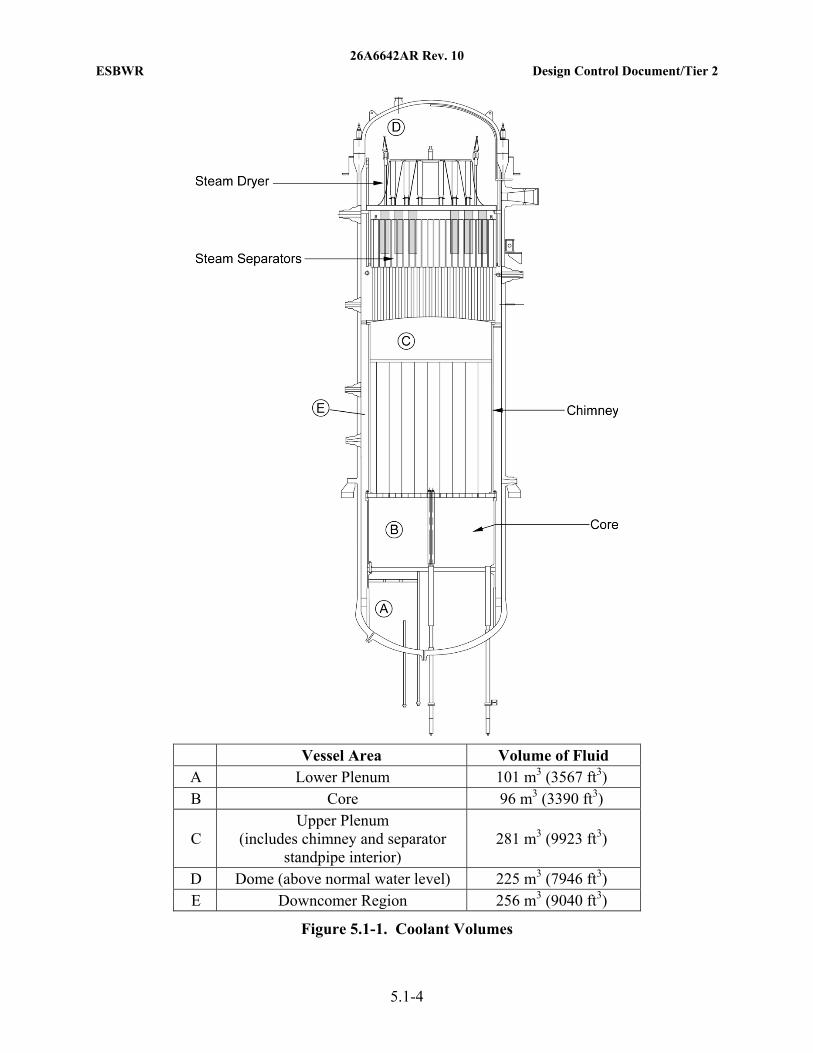
• Nuclear Boiler System (Figure 5.1-2);
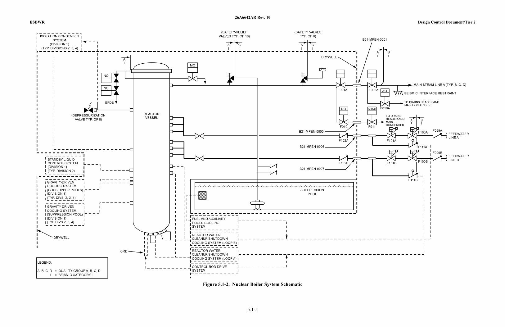
• Isolation Condenser System (Figure 5.1-3); and
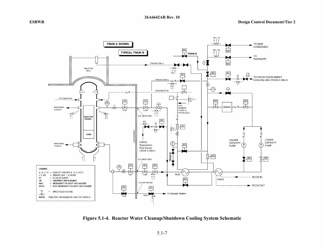
• Reactor Water Cleanup/Shutdown Cooling System (Figure 5.1-4).
5.1.3 Elevation Schematics
The elevation schematic showing the principal features of the reactor and connecting systems in relation to the containment are provided in Figure 1.2-7, Figure 1.2-10 and Figure 1.2-11.
5.1.4 COL Information
None.
5.1.5 References
None.
26A6642AR Rev. 10 ESBWR Design Control Document/Tier 2
5.1-4
Vessel Area Volume of Fluid A Lower Plenum 101 m3 (3567 ft3) B Core 96 m3 (3390 ft3)
C Upper Plenum
(includes chimney and separator standpipe interior)
281 m3 (9923 ft3)
D Dome (above normal water level) 225 m3 (7946 ft3) E Downcomer Region 256 m3 (9040 ft3)
Figure 5.1-1. Coolant Volumes
26A6642AR Rev. 10 ESBWR Design Control Document/Tier 2
5.1-5
Figure 5.1-2. Nuclear Boiler System Schematic
26A6642AR Rev. 10 ESBWR Design Control Document/Tier 2
5.1-6
Figure 5.1-3. Isolation Condenser System Schematic
26A6642AR Rev. 10 ESBWR Design Control Document/Tier 2
5.1-7
Figure 5.1-4. Reactor Water Cleanup/Shutdown Cooling System Schematic
26A6642AR Rev. 10 ESBWR Design Control Document/Tier 2
5.2-1
5.2 INTEGRITY OF REACTOR COOLANT PRESSURE BOUNDARY
This section discusses measures employed to provide and maintain the integrity of the RCPB.
5.2.1 Compliance with Codes and Code Cases
5.2.1.1 Compliance with 10 CFR 50.55a
The ESBWR meets the relevant requirements of the following regulations:
• 10 CFR 50, Appendix A, General Design Criterion (GDC) 1, as it relates to the requirement that safety-related structures, systems, and components are designed, fabricated, erected, and tested to quality standards commensurate with the importance of the safety function to be performed.
• 10 CFR 50.55a, as it relates to establishing minimum quality standards for the design, fabrication, erection, construction, testing and inspection of components within the RCPB and other safety-related fluid systems, by requiring conformance with appropriate editions of specified published industry codes and standards as indicated in Table 1.9-22.
Note: For seismic design of piping, the ESBWR conforms to Articles NB-3200, NB-3600, NC-3600, and ND-3600 of the ASME Boiler and Pressure Vessel Code, Section III, 1992 Edition with 1993 Addenda. For weld leg dimensions, when applying paragraph NB-3683.4(c)(1), or applying Footnote 11 to Figure NC-3673.2(b)-1, or applying Figure ND-3673.2(b)-1, the ESBWR conforms to the ASME Boiler and Pressure Vessel Code, Section III, 1989 Edition with no Addenda. All limitations and modifications specified in 10 CFR 50.55a(b)(1) are met.
To meet the requirements of GDC 1 and 10 CFR 50.55a, Regulatory Guide (RG) 1.26, “Quality Group Classification and Standards for Water-, Steam-, and Radioactive-Waste-Containing Components of Nuclear Power Plants,” is used. This regulatory guide describes an acceptable method for determining quality standards for Quality Group B, C, and D water- and steam-containing safety-related components of water-cooled nuclear power plants.
Tables 3.2-1 and 3.2-3 show the ASME B&PV Code applied to components. Code edition, applicable addenda, and component dates are in accordance with 10 CFR 50.55a.
5.2.1.2 Applicable Code Cases
The ESBWR meets the relevant requirements of the following regulations:
• 10 CFR 50, Appendix A, GDC 1, as it relates to the requirement that safety-related structures, systems and components are designed, fabricated, erected, and tested to quality standards commensurate with the importance of the safety function to be performed.
• 10 CFR 50.55a, as it relates to the rule that establishes minimum quality standards for the design, fabrication, erection, construction, testing, and inspection of certain components of BWR nuclear power plants by requiring conformance with appropriate editions of specified published industry codes and standards.
26A6642AR Rev. 10 ESBWR Design Control Document/Tier 2
5.2-2
• To meet the requirements of GDC 1 and 10 CFR 50.55a, the following Regulatory Guides (RGs) are used:
− RG 1.84, “Design, Fabrication, and Materials Code Case Acceptability, ASME Section III.” This guide lists those Section III ASME B&PV Code Cases oriented to design and fabrication that are acceptable to the Nuclear Regulatory Commission (NRC) staff for implementation in the licensing of nuclear power plants.
− RG 1.147, “Inservice Inspection Code Case Acceptability, ASME Section XI, Division 1.” This guide lists those Section XI ASME B&PV Code Cases that are acceptable to the staff for use in the in-service inspection of light-water-cooled nuclear power plants.
− RG 1.192, “Operation and Maintenance Code Case Acceptability, ASME OM Code.” This guide lists those ASME OM Code Cases that are acceptable to the NRC staff, with conditions or restrictions, for implementation of a program for in-service testing in light-water cooled nuclear power plants.
The reactor pressure vessel (RPV) and appurtenances and the RCPB piping and valves are designed, fabricated, and tested in accordance with the applicable edition of the ASME Boiler & Pressure Vessel Code (ASME Code), Section III, including addenda that were mandatory at the order date for the applicable components. Section 50.55a of 10 CFR 50 requires code case approval for Class 1, 2, and 3 components. These code cases contain requirements or special rules which may be used for the construction of pressure retaining components of Quality Group Classification A, B, and C. The various ASME B&PV Code cases that may be applied to components, subject to RG conditions are listed in Table 5.2-1.
RG 1.84, and 1.147 provide a list of ASME B&PV Code design and fabrication code cases that have been generically approved by the regulatory staff. ASME B&PV Code cases on this list may, for design purposes, be used until appropriately annulled. Annulled cases are considered active for equipment that has been contractually committed to fabrication prior to the annulment.
The use of the ASME OM Code, including the application of any OM Code Cases with the conditions and restrictions of RG 1.192, is described in Section 3.9.
5.2.2 Overpressure Protection
This subsection evaluates systems that protect the RCPB from overpressurization.
Overpressure protection for the RCPB, during power operation of the reactor, is in compliance with ASME B&PV Code, Section III, Article NB-7000. Subsubarticle NB-7120 requires that the design integrated overpressure protection be accomplished by any of three options including (a) by pressure relief devices with pressure sensing elements, (b) by the reactor shutdown system, or (c) by design without pressure relief devices such that the design specified service limits are not exceeded. The ESBWR integrated overpressure protection is ensured by application of the Reactor Protection System (RPS) to shutdown the reactor in combination with decay heat removal through the Isolation Condenser System (ICS) to suppress and control vessel pressure or by steam discharge through ten safety relief valves (SRVs) on the main steamlines with discharge piping from the SRVs into the suppression pool. Additional overpressure protection is provided by eight safety valves (SVs) that open at a set pressure above that of the SRVs and
26A6642AR Rev. 10 ESBWR Design Control Document/Tier 2
5.2-3
discharge through rupture disks directly to the drywell atmosphere. The SRVs and SVs, in conjunction with a reactor trip, limit peak pressure in the RPV during plant transients of a severity beyond those transients for which the ICS provides pressure-limiting effect.
Overpressure protection for the RCPB, during low temperature operation of the plant (startup, shutdown), is ensured by the application of pressure relieving systems that function during the low temperature operation. For BWRs, no special area of review is required because BWRs never operate in water-solid conditions.
The ESBWR overpressure protection system meets the relevant requirements of the following regulations:
• GDC 15, as it relates to the RCS and associated auxiliary, control, and protection systems being designed with sufficient margin to assure that the design conditions of the RCPB are not exceeded during any condition of normal operation, including anticipated operational occurrences (AOOs).
• GDC 14, as it relates to the RCPB being designed, fabricated of, erected, and tested so as to have an extremely low probability of abnormal leakage, rapidly propagating failure, and of gross rupture.
• GDC 30, as it relates to components, which are part of the RCPB, being designed, fabricated, erected, and tested to the highest quality standards practical.
The ESBWR design meets the recommendations of the Three Mile Island (TMI) action plan item II.D.1 in 10 CFR 50.34(f)(2)(x) regarding a test program and associated model development and testing to qualify RCS relief and safety valves for all fluid conditions expected under operating conditions, design basis transients and accidents. The ESBWR design also meets the recommendations of TMI action plan item II.D.3 in 10 CFR 50.34(f)(2)(xi) regarding SRV and SV position indication by providing open and closed indication of each valve.
Other specific acceptance criteria of GDC 15 met by ESBWR are as follows:
• For overpressure protection, the ICS has sufficient capacity to preclude actuation of the SRVs, in response to AOOs during normal plant operation (ASME B&PV Code, Section III, Service Level B Limit of 110% RCPB design pressure), when assuming the following conditions:
− The reactor is initially operating at licensed core thermal power level;
− All systems and core parameters are at values within normal operating range that produce the highest analyzed transient pressure; and
− All components, instrumentation, and controls function normally.
• The SRVs and SVs have sufficient capacity to limit the pressure to less than 120% of the RCPB design pressure (ASME B&PV Code, Section III, Service Level C Limit), during the most severe anticipated transients without scram pressurization transient. Also, sufficient margin is available to account for uncertainties in the design and operation of the plant assuming:
− The reactor is initially operating at a power level that produces the most severe overpressurization event; and

26A6642AR Rev. 10 ESBWR Design Control Document/Tier 2
5.2-4
− All systems and core parameters are at values within normal operating range, including uncertainties and technical specification limits that produce the highest anticipated pressure.
The SRV and SV discharge flows are based on their respective rated capacities as determined by certification testing in accordance with the ASME B&PV Code, Section III, for each type of valve. Full credit is taken for mechanical lift safety function of the SRVs designed in accordance with the requirements of the ASME Boiler and Pressure Vessel (B&PV) Code Section III. The valves are designed and constructed in accordance with ASME B&PV Code, Section III, NB 7510, Safety, Safety Relief, and Relief Valves, NB 7520, Pilot Operated Pressure Relief Valves, or NB 7540, Safety Valves or Pilot Operated Pressure Relief Valves with Auxiliary Actuating Devices.
5.2.2.1 Design Basis
Overpressure protection is provided in conformance with 10 CFR 50 Appendix A, GDC 15. Preoperational and startup procedures are given in Section 14.2.
Safety Design Bases
The nuclear pressure-relief system has been designed to:
• Prevent overpressurization of the Nuclear Boiler System (NBS) that could lead to the failure of the RCPB;
• Provide enhanced depressurization of the NBS, along with the depressurization valves (DPVs) described in Subsection 5.4.13, so that the GDCS can operate to protect the fuel barrier for LOCA break sizes that result in too slow a rate of RCPB depressurization relative to the reactor vessel coolant level drop;
• Direct SV steam discharge to limit jet impingement and generation of pool debris; and
• Permit verification of operability; and withstand adverse combinations of loadings and forces resulting from normal, upset, emergency, or faulted conditions.
Power Generation Design Bases
The ICS is described in Subsection 5.4.6. The nuclear pressure-relief by the SRVs and SVs has been designed to meet the following power generation bases:
• Discharge of the SRVs is directed into the containment suppression pool;
• SVs have a higher set pressure than the SRVs and discharge directly into the drywell atmosphere. Short discharge pipes with end-mounted rupture disks limit SV leakage from entering the drywell atmosphere during normal plant operation; and
• SRVs and SVs reclose following steam discharge so that maximum operational continuity is obtained.
Operating Experience
Operating experience is considered in selecting the design of SRVs and SVs, including Generic Safety Issue B-55, “Improved Reliability of Target Rock Safety Relief Valves”, NUREG-0763, “Guidelines for Confirmatory In-Plant Tests of Safety Relief Valve Discharges for BWR Plants”,
26A6642AR Rev. 10 ESBWR Design Control Document/Tier 2
5.2-5
IE Circular 79-18, “Proper Installation of Target Rock Safety Relief Valves”, and Bulletin 74-04, “Malfunction of Target Rock Safety Relief Valves”.
ASME B&PV Code
The ASME B&PV Code requires that each vessel designed to meet Section III, Nuclear Power Plant Components, be protected from overpressure under Service Level B conditions.
The SRV and SV setpoints are listed in Table 5.2-2 and satisfy the ASME B&PV Code specifications for safety valves.
The following criteria are used in selection of SRVs and SVs:
• Must meet requirements of ASME B&PV Code Section III, for Class 1 (Subsection NB) components;
• Must be qualified for 100% of nameplate steam discharge capacity at 103% of nameplate set pressure for the overpressure protection function; and
• Must meet other ASME B&PV Code, Section III, performance requirements necessary to provide the integrated design safety and relief functions.
The SRV and SV discharge piping is designed, installed, and tested to Class 3 (Subsection NC) requirements in accordance with ASME B&PV Code, Section III.
Safety Relief Valve Capacity
SRV and SV capacity is adequate to limit the NBS pressure, including in response to AOOs and pressure increasing transients, beyond the AOOs, to the requirements of ASME B&PV Code, Section III, up to and including applicable addenda. The essential ASME requirements that are met by this analysis follow.
The combined rated capacity of the pressure-relieving devices is sufficient so that the rise in pressure within the protected vessel does not exceed the applicable limits for the pressurization events described in Chapter 15.
5.2.2.2 System Description
5.2.2.2.1 Piping and Instrument Diagrams
The ICS is described in Subsection 5.4.6. Figure 5.1-2 and Figures 5.2-1 and 5.2-2 show the schematic location of the SV and SRV type pressure-relieving devices for:
• The reactor coolant system;
• The primary side of the auxiliary or emergency systems interconnected with the NBS; and
• Any blowdown or heat dissipation system connected to the discharge side of the pressure-relieving devices.
26A6642AR Rev. 10 ESBWR Design Control Document/Tier 2
5.2-6
5.2.2.2.2 Equipment and Component Description
Description
The NBS pressure-relief system consists of the ICS (see Subsection 5.4.6), and a set of ten SRVs and a set of eight SVs located on the main steamlines between the reactor vessel and the first isolation valve within the drywell. The SRVs and SVs are flange mounted onto forged outlet fittings located on the top of the main steamline (MSL) piping in the drywell. The pressure relief valve type used in the ABWR is a spring-closed safety valve design that has a favorable operating history in boiling water reactor (BWR) application. The NBS pressure relief valves are based on spring-closed safety valve designs in use at operating BWR plants, including the ABWR SRV design.
The SRVs have relief-mode actuation devices connected to the ADS logic and to manual controls in the main control room. Each SRV has a discharge line routed to a point submerged below the minimum water level of the wetwell pool. The discharge line terminates into a four-arm quencher (Figure 5.2-3) that distributes the steam flow into many small streams for efficient steam condensation in the pool. The discharge lines are classified as Quality Group C and Seismic Category I. Two vacuum relief valves are provided on each SRV discharge line to minimize initial rise of water in discharge piping and prevent drawing an excessive amount of water into the line as a result of steam condensation following termination of relief operation.
The eight SVs have no relief-mode capability and discharge through individual discharge stacks that have a rupture disc at the end. Each SV discharge pipe is configured as a vertically oriented stack with the rupture disk mounted to the upper end. The vertically directed discharge steam jet is directed against a blast shield/deflection plate. A design exclusion zone is established in the vicinity of the stack and deflection plate to limit jet impingement against safety-related systems, structures and components, or against pipe insulation or coated surfaces that may result in the generation of debris that could enter the wetwell or the GDCS pools. Each discharge stack has a drain line that drains condensed steam leakage to the suppression pool and is routed to a submerged discharge location in a wetwell vent to suppress any steam discharge. The SVs discharge through the rupture discs to the drywell.
The ICS, SRVs, and SVs protect against overpressure of the NBS including the system interfaces that are part of RCPB, and the SRVs permit manually controlled or automatic NBS depressurization, when required in support of the GDCS function.
The SRVs and SVs provide two main protection functions:
• Overpressure safety operation (all 18 of the valves are actuated by increasing inlet steam pressure to prevent nuclear system overpressurization); and
• Depressurization operation (the ten SRVs are actuated by the ADS logic to support the emergency core cooling system for events involving LOCA breaks in the NBS or a connected system process barrier).
Chapter 15 discusses the events that are expected to activate the SRVs and SVs. It also summarizes the number of valves expected to operate in safety (increasing steam pressure lift) mode of operation during the initial blowdown of the valves and the expected duration of this first blowdown. In response to an event that activates the SRVs and/or SVs, operation of the ICS, or if ICS is unavailable, remote manual sequential actuation of the SRVs from the control
26A6642AR Rev. 10 ESBWR Design Control Document/Tier 2
5.2-7
room is recommended to control NBS pressure below the safety lift set pressures. This will minimize the total number of these discharges with the intent of minimizing containment and NBS system loads, and extend valve seat life.
All 18 valves are opened by the safety (increasing steam pressure lift) mode of operation. The SRVs or SVs open by steam pressure when the main or pilot disk opens quickly in response to the steam inlet pressure exceeding the restraining spring force and frictional forces. The condition at which this action is initiated is termed the “popping pressure” and corresponds to the set-pressure value stamped on the nameplate of the valve. Spring-closed SRVs and SVs operate by steam pressure acting on the main disk in the open direction. Piloted SRVs and SVs operate by steam pressure acting on the main disk piston in the open direction (the piston is initially unpressurized).
Spring-closed SRVs and SVs close when the pressure for acting under the main disk decreases until the spring force acting over the main disk seats the disk and stops discharge flow. Piloted SRVs and SVs close when the pressure force acting under the pilot disk decreases until the spring force acting over the pilot disk seats the pilot disk and opens the piston chamber exhaust port, causing the piston force to decrease rapidly and allowing a spring under the piston to lift the piston and main disk. The main disk enters the discharge flow stream and is forced against the seat rapidly to stop the discharge flow.
In addition to the safety mode of operation, the ten SRVs are opened by the power-assisted relief mode of operation.
The relief mode of operation is initiated when an electrical signal is received at any of the solenoid valves located on the SRV assembly. The solenoid valve(s) open, allowing steam pressurization of the main disk piston, which pushes the main disk open; or nitrogen pressurization of the pneumatic cylinder piston lower side, which pushes the piston and the rod upwards to act on the main or pilot disk lifting mechanism to open the valve. This action allows steam to discharge through the SRV until the inlet-to-outlet pressure differential is near or equal to zero or the solenoid valve is closed. Relief mode SRV actuation can be initiated over a wide range of NBS pressure.
For an SRV that is equipped with a pneumatic operator, the design is so arranged that if the pneumatic operator malfunctions it does not prevent the valve from opening when steam inlet pressure reaches the mechanical safety lift set pressure. A pneumatic accumulator, and check valve are required to support the remote-manual and ADS-activated functions of the valve. The accumulator and check valve ensures that the valve opens via the pneumatic operator following a failure of the pneumatic pressure source. The accumulator capacity is sufficient for one actuation at drywell design pressure.
For overpressure operation (self-actuated or mechanical lift mode), the SRV or SV spring load establishes the safety opening setpoint pressure, and each SRV or SV is set to open at a setpoint value established according to the designated maximum analytical limit in Table 5.2-2, respectively. In accordance with the ASME B&PV Code, the full lift of this mode of operation is attained at a pressure no greater than 3% above the setpoint. The opening time for the SRVs, from the time the pressure exceeds the valve set pressure to the time the valve is fully open, is less than 0.5 second.
26A6642AR Rev. 10 ESBWR Design Control Document/Tier 2
5.2-8
The ADS has the capability to activate the NBS pressure relief system, including the SRVs and DPVs, and is evaluated in Subsection 6.3.2.8.2 and Subsection 7.3.1.1. The ADS automatically depressurizes the nuclear system sufficiently to permit the GDCS to operate.
Design Parameters
The specified operating transients for components within the RCPB are presented in Section 3.9. Subsection 3.7.1 provides a discussion of the input criteria for design of Seismic Category I structures, systems, and components. The design requirements established to protect the principal components of the RCS against environmental effects are presented in Section 3.11.
Safety Relief Valves
The design pressure and temperature of the valve inlet is 9.48 MPa gauge (1375 psig) at 307°C (585°F).
The valves have been designed to achieve the maximum practical number of actuations consistent with state-of-the-art technology.
5.2.2.2.3 Mounting of Safety Relief Valves
The SRVs and SVs are installed vertically on the main steam piping. The design criteria and analysis methods for considering SRV discharge loads are contained in Section 3.9.
5.2.2.2.4 Applicable Codes and Classification
The vessel overpressure protection system is designed to satisfy the requirements of Section III of the ASME B&PV Code. The general requirements for protection against overpressure of Section III of the ASME B&PV Code recognize that reactor vessel overpressure protection is one function of the reactor protective systems and allows the integration of pressure-relief devices with the protective systems of the nuclear reactor. Hence, credit is taken for the scram protective system as a complementary pressure protection device. The NRC has also adopted the ASME B&PV Code as part of their requirements in the Code of Federal Regulations (10 CFR 50.55a).
5.2.2.2.5 Material Specifications
Typical material specifications for pressure-retaining components of SRVs and SVs are listed in Table 5.2-4. All NBS relief and safety valve pressure-retaining materials comply with the requirements of the ASME B&PV Code, Section III, Article NB-2000.
5.2.2.3 Safety Evaluation
Results of the overpressure protection evaluation are provided in Subsection 15.5.1. The system is designed to satisfy the requirements of Section III of the ASME B&PV Code.
5.2.2.4 Testing and Inspection Requirements
The inspection and testing of applicable SRVs and SVs utilizes a quality assurance program, which complies with Appendix B of 10 CFR 50.
26A6642AR Rev. 10 ESBWR Design Control Document/Tier 2
5.2-9
The SRVs and SVs are tested at a suitable test facility in accordance with quality control procedures to detect defects and to prove operability prior to installation. The following tests are conducted:
• Hydrostatic test at specified test conditions (ASME B&PV Code requirement based on design pressure and temperature).
• Thermally stabilize the valve to perform quantitative steam leakage testing at 1.03 MPaG (150 psig) below the nameplate value with an acceptance criterion not to exceed 0.45 kg/hr (1 lbm/hr) leakage.
• Full flow SRV test for set pressures and blowdown where the valve is pressurized with saturated steam, with the pressure rising to the valve set pressure (during production testing the SRV is adjusted to open at the nameplate set pressure ± 1%).
• Response time test where each valve is tested to demonstrate acceptable response time based on system requirements. The valves are installed as received from the factory. The valve manufacturer certifies that design and performance requirements have been met. This includes capacity and blowdown requirements. The setpoints are adjusted, verified, and indicated on the valves by the vendor. Specified manual and automatic initiated signal for power actuation of each valve is verified during the preoperational test program.
• It is not practical to test the SRV or SV setpoints while the reactor is at power. Steam or other pressure-lift testing is only performed with a valve removed from containment and installed on an appropriate test facility. The valves are mounted on flanges and can be removed for maintenance or bench testing and reinstalled during normal plant shutdowns. The valves are tested in accordance with the requirements of the in-service testing program as discussed in Subsection 3.9.6 and Table 3.9-8. The external and flange seating surfaces of all SRVs and SVs are 100% visually inspected when the valves are removed for maintenance or bench testing. Valve operability is verified during the preoperational test program as discussed in Section 14.2. As a part of the preoperational and startup testing of the main steamlines, movement of the SRV discharge lines are monitored.
5.2.2.5 Instrumentation Requirements
Each SRV discharge line contains a temperature element, which provides an indication of seat leakage within the valve or confirmation of valve opening. The temperature element provides a signal to an indicator and an alarm in the main control room. Each SRV and SV has a position indicator, which provides a signal to the main control room for indication of open and closed position.
5.2.3 Reactor Coolant Pressure Boundary Materials
This subsection addresses materials of the RCPB other than the RPV, which is covered in Subsection 5.3.1.
26A6642AR Rev. 10 ESBWR Design Control Document/Tier 2
5.2-10
The ESBWR meets the requirements of 10 CFR 50 given below:
• GDC 1 and 30, as they relate to quality standards for design, fabrication, erection and testing;
• GDC 4, as it relates to compatibility of components with environmental conditions;
• GDC 14 and 31, as they relate to extremely low probability of rapidly propagating fracture and gross rupture of the RCPB;
• Appendix B, Criterion XIII, as it relates to onsite material cleaning control;
• Appendix G, as it relates to materials testing and acceptance criteria for fracture toughness of the RCPB; and
• Section 50.55a, as it relates to quality standards applicable to the RCPB.
5.2.3.1 Material Specifications
This subsection discusses the specifications for pressure-retaining ferritic materials, nonferrous metals and austenitic stainless steels, including weld materials, that are used for each component (e.g., vessels, piping, pumps, and valves) of the RCPB. The adequacy and suitability of the ferritic materials, stainless steels, and nonferrous metals specified for the above applications are also discussed.
Table 5.2-4 lists the principal pressure-retaining materials and the appropriate material specifications for the RCPB components; all RCPB materials conform to the ASME B&PV Code, Section III, Article NB-2000.
5.2.3.1.1 Cryogenic Conditions
The specifications for pressure-retaining materials used for components of the RCPB do not include consideration for design with cryogenic service conditions. To eliminate the need for freeze seals on piping systems attached to the reactor pressure vessel, all power-operated equipment and valves that require maintenance have maintenance valves installed such that freeze seals will not be required.
5.2.3.2 Compatibility with Reactor Coolant
General corrosion and stress corrosion cracking induced by impurities in the reactor coolant can cause failures of the RCPB. The chemistry of the reactor coolant and any additives whose function is to control corrosion are reviewed in Subsections 5.4.8, 9.3.9 and 9.3.10. The compatibility of the materials of construction employed in the RCPB with the reactor coolant, contaminants, or radiolytic products to which the system is exposed has been considered. The extent of the corrosion of ferritic low alloy steels and carbon steels in contact with the reactor coolant has been considered. Similarly, consideration has been given to uses of austenitic stainless steels in the sensitized condition. Special attention has been given to the use of austenitic stainless steels in any condition in BWRs considering the oxygen content of BWR coolant.
5.2.3.2.1 PWR Chemistry of Reactor Coolant
Not applicable to BWRs.
26A6642AR Rev. 10 ESBWR Design Control Document/Tier 2
5.2-11
5.2.3.2.2 BWR Chemistry of Reactor Coolant
A brief review of the relationships between water chemistry variables and RCPB materials performance, fuel performance, and plant radiation fields is presented in this section. Further information may be obtained from Reference 5.2-3.
The major environment-related materials performance problem encountered to date in the RCPB of BWRs has been intergranular stress corrosion cracking (IGSCC) of sensitized austenitic stainless steel. IGSCC in sensitized material adjacent to welds in Type 304 and Type 316 stainless steel piping systems has occurred in the past. Substantial research and development programs have been undertaken to understand the IGSCC phenomenon and develop remedial measures. For the ESBWR, IGSCC resistance has been achieved through the use of IGSCC resistant materials such as Type 316 Nuclear Grade stainless steel and stabilized nickel-base niobium modified Alloy 600 and Alloy 82.
Much of the early remedy-development work focused on alternative materials or local stress reduction, but more recently the effects of water chemistry parameters on the IGSCC process have received increasing attention. Many important features of the relationship between BWR water chemistry and IGSCC of sensitized stainless steels have been identified.
Laboratory studies (References 5.2-1 and 5.2-2) have shown that, although IGSCC can occur in simulated BWR startup environments, most IGSCC damage probably occurs during power operation. The normal BWR environment during power operation is 286°C (547°F) water containing dissolved oxygen, hydrogen and small concentrations of ionic and non-ionic impurities (conductivity generally below 0.3µS/cm at 25°C (77°F)). It has been well documented that some ionic impurities (notably sulfate and chloride) aggravate IGSCC, and a number of studies have been made of the effect of individual impurity species on IGSCC initiation and growth rates (References 5.2-1 through 5.2-5). This work clearly shows that IGSCC can occur in water at 286°C (547°F) with 200 ppb of dissolved oxygen, even at low conductivity (low impurity levels), but the rate of cracking decreases with decreasing impurity content. Although BWR water chemistry guidelines for reactor water cannot prevent IGSCC, maintaining the lowest practically achievable impurity levels minimizes the rate of progression (References 5.2-3 and 5.2-6).
Stress corrosion cracking of ductile materials in aqueous environments is often restricted to specific ranges of corrosion potential, so a number of studies of impurity effects on IGSCC have been made as a function of either corrosion potential or dissolved oxygen content. The dissolved oxygen content is the major chemical variable in BWR type water that can be used to manipulate the corrosion potential in laboratory tests (Reference 5.2-7).
In-reactor and laboratory evidence indicates that carbon and low alloy steels tend to show improved resistance to environmentally assisted cracking with both increasing water purity and decreasing corrosion potential (Reference 5.2-8).
Fuel Performance Considerations
Nuclear fuel is contained in Zircaloy tubes that constitute the first boundary or primary containment for the highly radioactive species generated by the fission process; therefore, the integrity of the tubes must be ensured. Zircaloy interacts with the coolant water and some coolant impurities. This results in oxidation by the water, increased hydrogen content in the
26A6642AR Rev. 10 ESBWR Design Control Document/Tier 2
5.2-12
Zircaloy (hydriding), and, often, buildup of a layer of crud on the outside of the tube. Excessive oxidation, hydriding, or crud deposition may lead to a breach of the cladding wall.
Metallic impurities can result in neutron losses and associated economic penalties, which increase in proportion to the amount being introduced into the reactor and deposited on the fuel. With respect to iron oxide-type crud deposits, it can be concluded that operation within the BWR water chemistry guidelines provided in Table 5.2-5 (specifically the limits on feedwater iron levels) effectively precludes the buildup of significant deposits on fuel elements.
Radiation Field Buildup
The primary long-term source of radiation fields in most BWRs is Co60, which is formed by neutron activation of Co59. Corrosion products are released from corroding and wearing surfaces as soluble, colloidal, and particulate species. The formation of Co60
takes place after the corrosion products precipitate, adsorb, or deposit on the fuel rods. Subsequent re-entrainment in the coolant and deposition on out-of-core stainless steel surfaces leads to buildup of the activated corrosion products (such as Co60) on the out-of-core surfaces. The deposition may occur either in a loosely adherent layer created by particle deposition, or in a tightly adherent corrosion layer incorporating radioisotopes during corrosion and subsequent ion exchange. Water chemistry influences all of these transport processes. The key variables are the concentration of soluble Co60
in the reactor water and the characteristics of surface oxides. Thus, any reduction in the soluble Co60
concentration has positive benefits.
As a means to reduce radiation field buildup, cobalt content has been reduced in alloys to be used in high fluence areas such as fuel assemblies and control rods. In addition, cobalt base alloys used for pins and rollers in control rods have been replaced with non-cobalt alloys. Furthermore, cobalt content is restricted in stainless steel components in the reactor vessel and other selected stainless steel components that have large surface areas exposed to high flow rates toward the reactor vessel.
The RWCU/SDC system removes both dissolved and undissolved impurities, which can become radioactive deposits. Reduction of these radioactive deposits reduces occupational radiation exposure during operation and maintenance of the plant components.
Water quality parameters can have an influence on radiation buildup rates. In laboratory tests, the water conductivity and pH were varied systematically from a high purity base case. In each case, impurities increased the rate of Co60 uptake over that of the base case. The evidence suggests that these impurities change both the corrosion rate and the oxide film characteristics to adversely increase the Co60 uptake. Thus, controlling water purity should be beneficial in reducing radiation buildup.
Sources of Impurities
Various pathways exist for impurity ingress to the primary system. The most common sources of impurities that result in increases in reactor water conductivity are (1) condenser cooling water inleakage, (2) improper operation of ion exchange units, (3) air inleakage, and (4) radwaste recycle. In addition to situations of relatively continuous ingress, such as from low level condenser cooling water inleakage, transient events can also be significant. The major sources of impurities during such events are resin intrusions, organic chemical intrusions, inorganic chemical intrusions, and improper rinse of resins. Chemistry transients resulting from
26A6642AR Rev. 10 ESBWR Design Control Document/Tier 2
5.2-13
introduction of organic substances into the radwaste system comprise a significant fraction of the transients, which have occurred.
The condensate treatment system has two stages of water treatment. The first stage, high efficiency filters, is effective in removing insoluble solids, such as condensate system insoluble corrosion products. The second stage, the deep bed demineralizers, is effective in removing soluble solids, such as soluble corrosion products and impurities from condenser leakage.
The following factors are measured for control or diagnostic purposes to maintain proper water chemistry in the ESBWR:
Conductivity - Increasing levels of many ionic impurities adversely influence both the stress corrosion cracking behavior of RCPB materials and the rate of radiation field buildup, and may affect fuel performance. Therefore, conductivity levels in the reactor water are maintained at the lowest level practically achievable.
Chloride - Besides being promoters of IGSCC in sensitized stainless steels, chlorides are also capable of inducing transgranular cracking of nonsensitized stainless steels. Chlorides also promote pitting and crevice attack of most RCPB materials. Chlorides are normally associated with cooling water inleakage, but inputs via radwaste processing systems have also occurred.
Sulfate - Besides promoting IGSCC of sensitized Type 304 stainless steel in BWR-type water (in laboratory tests), sulfates have also been implicated in environment-assisted cracking of high-nickel alloys and carbon and low-alloy steels. Sulfate ingress can result from cooling water inleakage or resin ingress.
Oxygen - Besides being a major contributor to IGSCC of sensitized stainless steels, reduction of oxygen content is known to reduce the tendency for pitting and cracks of most plant materials.
During power operation, most of the oxygen content of reactor water is due to the radiolysis of water in the core and, therefore, oxygen control cannot be achieved through traditional chemistry and operational practices. Reactor water oxygen control to low, plant-specific levels can be obtained through hydrogen injection, if a Hydrogen Water Chemistry System (HWCS) (see Subsection 9.3.9) is installed. Control of reactor water oxygen during startup/hot standby is accomplished by utilizing the deaeration capabilities of the condenser. Carbon steels exhibit minimal general corrosion and release rates in water with a conductivity less than 0.1µS/cm if the concentration of oxygen is in the range of 15 to 200 ppb.
Regulation of reactor feedwater dissolved oxygen to 30-200 ppb with a target of less than 100 ppb during power operation minimizes corrosion of the Condensate and Feedwater System and reduces the possibility of locally increasing reactor water oxygen concentrations. For oxygen concentrations below 15 ppb, the data indicates an increase in the corrosion and corrosion product release for carbon steels.
Iron - High iron inputs into the reactor are associated with excessive fuel deposit buildup. Proper regulation of feedwater purity and dissolved oxygen levels minimizes iron transport to the reactor. This, in turn, minimizes fuel deposits and assists in controlling radiation buildup.
Fluoride - Fluoride promotes many of the same corrosion phenomena as chloride (including IGSCC) and may also cause corrosion of Zircaloy core components. If fluoride is present, it is measured regularly for diagnostic purposes.
26A6642AR Rev. 10 ESBWR Design Control Document/Tier 2
5.2-14
Organics - Organic compounds can be introduced into the RCPB via turbine or pump oil leakage, radwaste, or makeup water systems. Of particular concern is the possibility that halogenated organic compounds (e.g., cleaning solvents) may pass through the radwaste systems and enter the RCPB, where they decompose, releasing corrosive halogens (e.g., chlorides and fluorides).
Silica - Silica, an indicator of general system cleanliness, provides a valuable indication of the effectiveness of the RWCU/SDC system. Silica inputs are usually associated with incomplete silica removal in makeup water or radwaste systems.
pH - There are difficulties of measuring pH in low conductivity water. Nevertheless, pH of the liquid environment has been demonstrated to have an important influence on IGSCC initiation times for smooth stainless steel specimens in laboratory tests. In addition, pH can serve as a useful diagnostic parameter for interpreting severe water chemistry transients.
Electrochemical Corrosion Potential - The electrochemical corrosion potential of a metal is the potential it attains when immersed in a water environment. The electrochemical corrosion potential is controlled by various oxidizing agents, including copper and radiolysis products. At low reactor water conductivities, operating strategies that limit the electrochemical corrosion potential of stainless steel suppress IGSCC progression.
Feedwater Hydrogen Addition Rate - A HWCS is not part of the ESBWR Standard Plant design as stated in Subsection 1.2.2.12.13. However, if a HWCS is connected, a direct measurement of the feedwater hydrogen addition rate is made using the hydrogen addition system flow measurement device and is used to establish the plant-specific hydrogen flow requirements to satisfy the electrochemical corrosion potential limit of stainless steel. Subsequently, the addition rate measurements are used to help diagnose the origin of unexpected electrochemical corrosion potential changes.
Reactor Water Dissolved Hydrogen - If a HWCS is connected, a direct measurement of the dissolved hydrogen content in the reactor water serves as a cross check against the hydrogen gas flow meter in the injection system to confirm the actual presence and magnitude of the hydrogen addition rate.
Main Steamline Radiation Level - The major activity in the main steamline is N16 produced by
a (n, p) reaction with O16 in the reactor water. If a HWCS is connected, the fraction of the N16
that volatilizes with the steam increases with increased dissolved hydrogen. The main steamline radiation monitor readings increase with the hydrogen addition rate.
The major impurities expected in the ESBWR under certain operating conditions are listed in Table 5.2-5.
To support water quality specifications flow-assisted corrosion resistant low alloy steels are to be used in susceptible steam extraction and drain lines. Stainless steels are considered for baffles, shields, or other areas of severe duty. Provisions are made to add nitrogen gas to extraction steamlines, feedwater heater shells, and drain piping to minimize corrosion during layup. Alternatively, the system may be designed to drain while hot so that dry layup can be achieved.
The potential deterioration of ESBWR carbon steel piping from flow-assisted corrosion due to high velocity single-phase water flow and two-phase steam/water flow is addressed by appropriate control of hydrodynamic and environmental conditions.
26A6642AR Rev. 10 ESBWR Design Control Document/Tier 2
5.2-15
Water quality specifications for the ESBWR require the condenser to be designed and erected to minimize tube leakage and to facilitate maintenance. Condenser tubes and tube sheets are made of titanium or stainless steel alloys. Appropriate features are incorporated to detect leakage and segregate the source. The valves controlling the cooling water to the condenser sections are required to be operable from the control room so that a leaking section can be sealed off quickly.
Irradiation Assisted Stress Corrosion Cracking (IASCC) Considerations
Based on current knowledge, it is well known that reactor coolant does have direct effects on stress corrosion cracking and specifically IGSCC. As documented in the industry guidelines, reactor coolant impact includes the effects of corrosion potential as well as conductivity. Irradiated assisted stress corrosion cracking is associated with degradation that occurs as austenitic stainless steel material in the core region experiences material changes due to the effects of radiation. These effects include material hardening as well as radiation induced segregation. It is accepted that the threshold for IASCC degradation occurs when components are subjected to a combination of cumulative fluence greater than 5x10²⁰ n/cm2 @ E>1 MeV with applied stress levels in the component(s). Extensive tests have also shown that IASCC has not occurred at fluence levels below 5x10²⁰ n/cm2 @ E>1 MeV even at high stress levels in the component(s). In summary, experiments indicate that as fluence increases above this threshold of 5x10²⁰ n/cm2 @ E>1 MeV, the stress to initiate IASCC decreases.
It is known that the material causal factors that are important for IASCC, material hardening and segregation, are the same factors that lead to IGSCC; therefore the effects of water chemistry are similar. Improvement of reactor water chemistry to limit the susceptibility to IGSCC will have an indirect beneficial effect on subsequent IASCC as well. Additionally, for material that has been subjected to fluences greater than 5x10²⁰ n/cm2 @ E>1 MeV, improved water chemistry will also have a beneficial effect on cracking behavior. Therefore, water quality in accordance with current industry guidelines is beneficial to control IGSCC as well as IASCC.
Several approaches are being used to prevent IASCC. These include measures to prevent IGSCC early in life such as material selection, fabrication and process controls, water chemistry controls, and measures to prevent IASCC later in life such as design measures to locate welds away from the highest fluence regions and those items listed above to mitigate IGSCC (see also Subsection 4.5.2.1).
5.2.3.2.3 Compatibility of Construction Materials with Reactor Coolant
The construction materials exposed to the reactor coolant consist of the following:
• Solution-annealed austenitic stainless steels (both wrought and cast), Types 304, 304L, 316, 316L and XM-19;
• Nickel-based alloy (including niobium modified Alloy 600 and X-750);
• Carbon steel and low alloy steel;
• Some 400-series martensitic stainless steel (all tempered at a minimum of 595°C (1103°F));
• Colmonoy and Stellite hardfacing material (or equivalent); and
• Precipitation hardening stainless steels, 17-4PH and XM-13 in the H1100 condition.
26A6642AR Rev. 10 ESBWR Design Control Document/Tier 2
5.2-16
All of these construction materials are resistant to stress corrosion in the BWR coolant. General corrosion on all materials except carbon and low alloy steel is negligible. Conservative corrosion allowances are provided for all exposed surfaces of carbon and low alloy steels.
The requirements of GDC 4 relative to compatibility of components with environmental conditions are met by compliance with the applicable provisions of the ASME B&PV Code and by compliance with the recommendations of RG 1.44.
Contaminants in the reactor coolant are controlled to very low limits. These controls are implemented by limiting contaminant levels of elements (such as halogens, S, Pb) to as low as possible in miscellaneous materials used during fabrication and installation. These materials (such as tapes, penetrants) are completely removed and cleanliness is assured. Lubricant and gasket materials that remain in contact with the coolant during operation are evaluated on that basis. No detrimental effects occur on any of the materials from allowable contaminant levels in the high purity reactor coolant. Expected radiolytic products in the BWR coolant have no adverse effects on the construction materials.
For IGSCC resistance, weld filler material used for austenitic stainless steel base metals is Type 308L/316L/309L/309MoL with an average ferrite content not less than 8 FN (ferrite number). For cast austenitic stainless steel material used as part of the RCPB or reactor vessel internals component fabrications, the percent ferrite is calculated using Hull’s equivalent factors as indicated in NUREG/CR-4513, Rev. 1 (May 1994). The limitation placed upon the delta ferrite in austenitic stainless steel castings is 8% minimum and a maximum value of 20%. The maximum limit is used for those castings designed for a 60-year life in order to limit the effects of thermal aging degradation.
5.2.3.2.4 Compatibility of Construction Materials with External Insulation
All non-metallic insulation applied to austenitic stainless steel meets RG 1.36.
5.2.3.3 Fabrication and Processing of Ferritic Materials
This subsection discusses fracture toughness properties of ferritic materials used for pressure-retaining components of the RCPB, the control of welding in ferritic steels, and the requirements and methods for nondestructive examination (NDE) of ferritic wrought seamless tubular products used for ASME Class 1 components of nuclear power plants as specified in the ASME B&PV Code.
5.2.3.3.1 Fracture Toughness
All Class 1 carbon steel components are made from high toughness grade material.
In addition, all ferritic components comply with ASME B&PV Code requirements in accordance with the following:
• The ferritic materials used for piping, pumps, and valves of the RCPB are usually 63.5 mm (2.5 in.) or less in thickness. Impact testing is performed in accordance with NB-2332 for thicknesses of 63.5 mm (2.5 in.) or less. Impact testing is performed in accordance with ASME B&PV Code Paragraph NB-2331 for thickness greater than 63.5 mm.
26A6642AR Rev. 10 ESBWR Design Control Document/Tier 2
5.2-17
• Materials for bolting with nominal diameters exceeding 25.4 mm (1 in.) are required to meet both the 0.64 mm (0.025 in.) lateral expansion specified in NB-2333 and the 61 J (45 ft.-lbf) Charpy V value. The 61 J (45 ft.-lbf) requirement of the ASME B&PV Code that applies to bolts over 101.6 mm (4 in.) in diameter, is conservatively applied to nominal bolt diameters exceeding 25.4 mm (1 in.).
• The reactor vessel complies with the requirements of NB-2331 and 10 CFR 50 Appendix G. The reference temperature is established for all required pressure-retaining materials used in the construction of Class 1 vessels. This includes plates, forgings, weld material, and heat-affected zone. The reference temperature differs from the nil ductility temperature in that, in addition to passing the drop weight test, three Charpy V-Notch specimens (transverse) must exhibit 68 J (50 ft.-lbf) absorbed energy and 0.89 mm (0.035 in.) lateral expansion at 33°C (91°F) above the reference temperature. The core beltline material must meet 102 J (75 ft.-lbf) absorbed upper shelf energy. Consideration has been given to the effects of irradiation on beltline fracture toughness by controlling the chemical composition of vessel beltline materials.
• Calibration of instrument and equipment meets the requirements of the ASME B&PV Code, Section III, Paragraph NB/NC-2360.
5.2.3.3.2 Control of Welding
RG 1.50: Control of Preheat Temperature Employed for Welding of Low-Alloy Steel
RG 1.50 delineates preheat temperature control requirements and welding procedure qualifications supplementing those in ASME Sections III and IX.
Low-alloy steel is used only in RPV and feedwater piping. Other ferritic components in the RCPB are fabricated from carbon steel materials.
Preheat temperatures employed for welding of low alloy steel meet or exceed the recommendations of ASME B&PV Code Section III, Subsection NB and Appendix D, Article D-1000 as supplemented by RG 1.50. Components are either held for an extended time at preheat temperature to assure removal of hydrogen, or preheat is maintained until post-weld heat treatment. The minimum preheat and maximum interpass temperatures are specified and monitored.
All full penetration pressure-retaining welds are volumetrically examined.
RG 1.34: Control of Electroslag Weld Properties
Electroslag welding is not allowed on structural weld joints of low alloy steel.
RG 1.71: Welder Qualification for Areas of Limited Accessibility
Welder qualification for areas of limited accessibility is discussed under RG 1.71 in Subsection 5.2.3.4.2 of this report.
Moisture Control for Low Hydrogen, Covered Arc Welding Electrodes
Suitable identification, storage, and handling of electrodes, flux, and other welding materiel are maintained. Precautions are taken to minimize absorption of moisture by electrodes and flux.
26A6642AR Rev. 10 ESBWR Design Control Document/Tier 2
5.2-18
5.2.3.3.3 Nondestructive Examination of Tubular Products
Wrought tubular products that are used for pressure-retaining components of the RCPB are subject to the examination requirements of ASME B&PV Code Section III, Subsection NB. Seamless tubular products are examined according to NB-2550, welded tubular products according to NB-2560, and cast tubular products according to NB-2570.
These RCPB components meet 10 CFR 50 Appendix B requirements and the ASME B&PV Code requirements, thus assuring adequate control of quality for the products.
5.2.3.4 Fabrication and Processing of Austenitic Stainless Steels
Austenitic stainless steels in a variety of product forms are used for construction of a limited number of pressure-retaining components in the RCPB. Process controls are exercised during various stages of component manufacturing and reactor construction to avoid severe sensitization of the material and to minimize exposure of the stainless steel to contaminants that could lead to stress corrosion cracking.
5.2.3.4.1 Avoidance of Stress/Corrosion Cracking
Avoidance of Significant Sensitization
When austenitic stainless steels are heated in the temperature range 427°C - 982°C (801°F - 1800°F), they are considered to become “sensitized” or susceptible to intergranular corrosion. The ESBWR design complies with RG 1.44 and with the guidelines of Generic Letter 88-01 and NUREG-0313 Revision 2, to avoid sensitization through the use of reduced carbon content and process controls.
All austenitic stainless steels are supplied in the solution heat treated condition and special sensitization tests are applied to confirm and assure proper heat treatment. For applications where stainless steel surfaces are exposed to reactor water at temperatures above 93°C (199°F) in welded applications where solution heat treatment is not performed, nuclear grade materials (carbon content ≤ 0.02%) are used.
During fabrication, any heating operation (except welding) above 427°C (801°F) is avoided, unless followed by solution heat treatment. During welding, heat input is controlled. The interpass temperature is also controlled. Where practical, shop welds are solution heat treated.
Process Controls to Minimize Exposure to Contaminants
Process controls are exercised during all stages of component manufacturing and construction to minimize contaminants. Cleanliness controls are applied prior to any elevated temperature treatment. Exposure to contaminants capable of causing stress/corrosion cracking of austenitic stainless steel components are avoided by carefully controlling all cleaning and processing materials which contact the stainless steel during manufacture, construction, and installation.
Special care is exercised to insure removal of surface contaminants prior to any heating operations. Water quality for cleaning, rinsing, flushing, and testing is controlled and monitored. Suitable protective packaging is provided for components to maintain cleanliness during shipping and storage. The degree of surface cleanliness obtained by these procedures meets the requirements of RG 1.37 and 1.44.
26A6642AR Rev. 10 ESBWR Design Control Document/Tier 2
5.2-19
Cold-Worked Austenitic Stainless Steels
Cold worked austenitic stainless steels are not used for RCPB components. Cold work controls are applied for ASME B&PV Code components made of austenitic stainless steel and follow the same requirements outlined in Subsection 4.5.2.4. During fabrication, cold work is controlled by applying limits in hardness, bend radii and surface finish on ground surfaces.
5.2.3.4.2 Control of Welding
General Welding Controls
For general welding controls on austenitic stainless steel and nickel base alloy components, refer to Subsection 4.5.2.2.
Avoidance of Hot Cracking
RG 1.31 describes the acceptable method of implementing requirements with regard to the control of welding when fabricating and joining austenitic stainless steel components and systems.
Written welding procedures that are approved by General Electric Hitachi Nuclear Energy (GEH) are required for all primary pressure boundary welds performed for material fabrication and plant construction. These procedures shall comply with the requirements of Sections III and IX of the ASME B&PV Code and applicable NRC regulatory guides.
All austenitic stainless steel weld filler materials are required by specification to have an average minimum delta ferrite content of 8 FN (ferrite number) and a maximum of 20 FN for 308L and 16 FN for 316L as determined on undiluted weld pads by magnetic measuring instruments calibrated in accordance with AWS Specification A4.2.
RG 1.34: Electroslag Welds
See RG 1.34 in Subsection 5.2.3.3.2.
RG 1.71: Welder Qualification for Areas of Limited Accessibility
RG 1.71 requires that weld fabrication and repair for wrought low-alloy and high-alloy steels or other materials such as static and centrifugal castings and bimetallic joints comply with fabrication requirements of Sections III, VIII and IX of the ASME B&PV Code. It also requires additional performance qualifications for welding in areas of limited access.
All ASME Section III welds are fabricated in accordance with the requirements of Sections III and IX of the ASME B&PV Code. There are few restrictive welds involved in the fabrication of ESBWR components. Welder qualification for welds with the most restrictive access is accomplished by mockup welding. Mockups are examined by sectioning and radiography (or ultrasonic (UT)).
The Acceptance Criterion II.3.b(3) of SRP Subsection 5.2.3 is based on RG 1.71. The ESBWR design meets the intent of this regulatory guide by utilizing the following alternate approach.
When access to a non-volumetrically examined ASME Section III production weld (1) is less than 300 mm (11.8 in.) in any direction and (2) allows welding from one access direction only, such weld and repairs to welds in wrought and cast low alloy steels, austenitic stainless steels and high nickel alloys and in any combination of these materials shall comply with the
26A6642AR Rev. 10 ESBWR Design Control Document/Tier 2
5.2-20
fabrication requirements specified in ASME B&PV Code Section III and with the requirements of Section IX invoked by Section III, supplemented by the following requirements:
• The welder performance qualification test assembly required by ASME Section IX shall be welded under simulated access conditions. An acceptable test assembly will provide a Section IX welder performance qualification required by this regulatory guide.
• If the test assembly weld is to be judged by bend tests, a test specimen shall be removed from the location least favorable for the welder. If this test specimen cannot be removed from a location prescribed by Section IX, an additional bend test specimen is required. If the test assembly weld is to be judged by radiography or UT, the length of the weld to be examined shall include the location least favorable for the welder.
• Records of the results obtained in welder accessibility qualification shall be as certified by the manufacturer or installer, shall be maintained and shall be made accessible to authorized personnel.
• For accessibility, when restricted access conditions obscure the welder's line of sight, the use of visual aids such as mirrors shall be used. The qualification test assembly shall be welded under the more restricted access conditions using the visual aid required for production welding.
• Surveillance of accessibility qualification requirements is performed along with normal surveillance of ASME Section IX performance qualification requirements.
5.2.3.4.3 Nondestructive Examination of Tubular Products
For discussion of nondestructive examination of tubular products, refer to Subsection 5.2.3.3.3.
5.2.4 Preservice and In-service Inspection and Testing of Reactor Coolant Pressure Boundary
This subsection describes the preservice and in-service inspection and system pressure test programs for NRC Quality Group A, ASME B&PV Code, Class 1 items. It describes these programs implementing the requirements of Subsection IWB of the ASME B&PV Code Section XI.1
According to the ASME B&PV Code, Section XI, either UT or radiographic (RT) examination may be used for in-service inspection of welds in ASME B&PV Code Class 1 and 2 austenitic and dissimilar metal (DM) welds. The COL Applicant is responsible for developing a plan and providing a full description of its use during construction, preservice inspection, in-service inspection, and during design activities for components that are not included in the referenced certified design, to preserve accessibility to piping systems to enable NDE of ASME B&PV Code Class 1 austenitic and DM welds during in-service inspection (COL item 5.2-3-A).
10 CFR 50.55a prescribes Section XI Editions and Addenda applicable to in-service inspection programs, subject to limitations and modifications found therein. Additionally, 10 CFR 50.55a provides an allowance to request alternatives to or relief from ASME B&PV Code requirements.
1 Items as used in this subsection are products constructed under a certificate of authorization (NCA-3120) and material (NCA-1220). See Section III, NCA-1000, footnote 2.
26A6642AR Rev. 10 ESBWR Design Control Document/Tier 2
5.2-21
Section XI requirements can be modified by invoking approved Section XI ASME B&PV Code Cases. Approved ASME B&PV Code Cases are listed in RG 1.147.
The ESBWR is designed for the performance of preservice and in-service inspections including consideration of the requirements of the ASME B&PV Code, Section XI, Edition/Addenda as specified in Table 1.9-22. The development of preservice and in-service inspection programs is the responsibility of the licensee and shall be based on the ASME B&PV Code, Section XI, Edition and Addenda approved in 10 CFR 50.55a(b) 12 months before initial fuel load. (See Subsection 5.2.6 for COL information requirements). The requirements are described in Subsections 5.2.4.1 through 5.2.4.10.
5.2.4.1 Class 1 System Boundary
Definition
The Class 1 system boundary for both preservice and in-service inspection programs and the system pressure test program includes all those items within the Class 1 and Quality Group A boundary on the piping and instrumentation schematics. Based on 10 CFR 50 and RG 1.26, the boundary includes the following:
• Reactor pressure vessel;
• Portions of the Main Steam System;
• Portions of the Feedwater System;
• Portions of the Standby Liquid Control System;
• Portions of the RWCU/SDC system;
• Portions of the ICS; and
• Portions of the GDCS.
Those portions of the above systems within the Class 1 boundary are those items that are part of the RCS up to and including any and all of the following:
• The outermost containment isolation valve in the system piping which penetrates reactor containment;
• The second of two valves normally closed during normal reactor operation in system piping which does not penetrate reactor containment;
• The reactor coolant system SRVs and DPVs; and
• The Main Steam and Feedwater systems up to and including the outermost containment isolation valve.
Exclusions
Portions of the system within the RCPB, as defined above, that are excluded from the Class 1 boundary in accordance with 10 CFR 50, Section 50.55a, are as follows:
• Those components where, in the event of postulated failure of the component during normal reactor operation, the reactor can be shut down and cooled down in an orderly manner, assuming makeup is provided by the reactor coolant makeup system only.
26A6642AR Rev. 10 ESBWR Design Control Document/Tier 2
5.2-22
• Components that are or can be isolated from the RCS by two valves (both closed, both open, or one closed and one open). Each such open valve is capable of automatic actuation and, if the other valve is open, its closure time is such that, in the event of postulated failure of the component during normal reactor operation, each valve remains operable and the reactor can be shut down and cooled down in an orderly manner, assuming makeup is provided by the reactor coolant makeup system only.
The description of portions of systems excluded from the RCPB does not address Class 1 components exempt from inservice examinations under ASME B&PV Code Section XI rules. The Class 1 components exempt from inservice examinations are described in ASME B&PV Code Section XI, IWB-1220, with the limitation of 10 CFR 50.55a(b)(2)(xi) which restricts the use of ASME Section XI to the 1989 Edition. This limitation excludes the use of paragraph IWB-1220(d). If any Class 1 welds are inaccessible due to being encased in concrete, buried underground, located inside a penetration, or encapsulated by a guard pipe, they are still considered to be within the scope of ASME Section XI and are subject to examination requirements.
5.2.4.2 Accessibility
All items within the Class 1 boundary are designed to provide access for the examinations required by ASME Section XI, IWB-2500. Additionally, considerations for accessibility are defined in IWA-1500 of Section XI. Items such as nozzle-to-vessel welds often may have inherent access restrictions when vessel internals are installed. Therefore, preservice examination shall be performed as necessary to achieve the required examination volume on these items prior to installation of internals, which would interfere with examination. Access is sufficient for the inservice examination of the volume described in ASME B&PV Code Case N-613-1.
[The ESBWR design includes specific access requirements, in accordance with 10 CFR 50.55a(g)(3), to support preferred UT or optional RT examinations. The design of each component and system takes into account the NDE method, UT or RT, that will be used to fulfill preservice inspection and in-service inspection examination requirements and will take into full consideration the operational and radiological concerns associated with the method selected to ensure that the performance of the required examination will be practical during commercial operation of the plant. Additionally, the design procedural requirements for the 3D layout of the plant include acceptance criteria regarding access for inspection equipment and personnel.]* However, with respect to any design activities for components that are not included in the referenced ESBWR certified design, it is the responsibility of the COL Applicant to preserve accessibility to piping systems to enable NDE of ASME B&PV Code Class 1 austenitic and DM welds during in-service inspection (COL item 5.2-3-A).
Reactor Pressure Vessel Access
Access for examinations of the RPV is incorporated into the design of the vessel, biological shield wall and vessel insulation as follows:
RPV Welds - The shield wall and vessel insulation behind the shield wall are spaced away from the RPV outside surface to provide access for remotely operated ultrasonic examination devices as described in Subsection 5.2.4.3. Access for the insertion of automated devices is provided
26A6642AR Rev. 10 ESBWR Design Control Document/Tier 2
5.2-23
through removable insulation panels and at shield wall hatches in the upper drywell area. Platforms are attached to the biological shield wall to provide access for installation of remotely operated examination devices.
RPV Head, RPV Studs, Nuts and Washers - The RPV head is dry stored on the refueling floor during refueling operations. Removable insulation is designed to provide access for manual ultrasonic examinations of RPV head welds. RPV nuts and washers are dry stored and are accessible for visual (VT-1) examination. RPV studs may be volumetrically examined in place or when removed.
Bottom Head Welds - Access to the bottom head to shell welds is provided from the lower drywell area through shield wall hatches and removable insulation panels around the cylindrical lower portion of the vessel. This design provides access for manual or automated ultrasonic examination equipment. Sufficient access is provided for partial penetration nozzle welds (i.e., CRD penetration and instrumentation nozzle welds) for performance of the visual VT-1 and VT-3 examinations. These welds are also accessible to perform the ASME B&PV Code required VT-2 examinations during system leakage testing as required by ASME B&PV Code Section XI, IWB-2500-1.
Reactor Vessel Sliding Support - Access is provided for visual examination of the RPV Sliding Support per Subsection IWF.
Piping, Pumps, Valves, and Supports – The design and physical arrangement of piping, pumps, valves, and supports provide personnel access to each weld location for performance of ultrasonic and surface (magnetic particle or liquid penetrant) examinations and sufficient access to supports for performance of the visual VT-1 and VT-3 examination. The design of the nuclear power plant structures, systems, and components provides access for the performance of inservice testing and in-service inspection as required by the applicable ASME B&PV Code. Working platforms are provided in some areas to facilitate servicing of pumps and valves. Platforms and ladders are provided for access to piping welds, including the pipe-to-reactor vessel nozzle welds. Removable thermal insulation is provided on welds and components, which require frequent access for examination or are located in high radiation areas. Welds are located to permit ultrasonic examination from at least one side, but where component geometries permit, access from both sides is provided.
Restrictions: For piping systems and portions of piping systems subject to volumetric and surface examination, the following piping designs are not used:
• Valve to Valve,
• Valve to Reducer,
• Valve to Tee,
• Elbow to Elbow,
• Elbow to Tee,
• Nozzle to Elbow,
• Reducer to Elbow,
• Tee to Tee, and
26A6642AR Rev. 10 ESBWR Design Control Document/Tier 2
5.2-24
• Pump to Valve.
Straight sections of pipe and spool pieces are added between fittings. The minimum length of the spool piece has been determined by using the formula L = 2T + 152 mm, where L equals the length of the spool piece (not including weld preparation) and T equals the pipe wall thickness.
*Text sections that are bracketed and italicized with an asterisk following the brackets are designated as Tier 2*. Prior NRC approval is required to change.
5.2.4.3 Examination Categories and Methods
5.2.4.3.1 Examination Categories
The examination category of each item in accordance with ASME Section XI, IWB-2500 is listed in the preservice and in-service inspection programs. The items are listed by system and line number where applicable. The preservice and in-service inspection programs state the method of examination for each item.
The preservice examination is performed once in accordance with ASME Section XI, IWB-2200, with the exception of examinations specifically excluded by ASME Section III NB-5283 and Section XI from preservice requirements, such as VT-3 examination of valve body and pump casing internal surfaces (B-L-2 and B-M-2 examinations categories, respectively) and the visual VT-2 examinations for category B-P.
5.2.4.3.2 Examination Methods
Ultrasonic Examination of the Reactor Vessel
Ultrasonic examination for the RPV is conducted in accordance with the ASME B&PV Code, Section XI. There are currently no known access limitations for UT examination of the ESBWR reactor vessel. It is, therefore, expected that the reactor vessel may be completely examined by UT. The design to perform preservice inspection on the reactor vessel is based on the requirements of the ASME B&PV Code Section XI, specified in Table 1.9-22. For the required preservice examinations, the reactor vessel meets the acceptance standards of Section XI, IWB-3510. The RPV shell welds are designed for 100% accessibility for both preservice and in-service inspection. RPV shell welds may be examined from the inside or outside diameter surfaces (or a combination of those techniques) using automated ultrasonic examination equipment. The RPV nozzle-to-shell welds are 100% accessible for preservice inspection but might have limited areas that may not be accessible from the outer surface for inservice examination techniques.
In most cases, inner radius examinations are performed from the outside of the nozzle using several compound angle transducer wedges to obtain complete coverage of the required examination volume. Alternatively, nozzle inner radius examinations may be performed using enhanced visual techniques, as allowed by 10 CFR 50.55a(b)(2)(xxi).
Visual Examination
Visual examination methods VT-1, VT-2 and VT-3 are be conducted in accordance with ASME Section XI, IWA-2210. In addition, VT-2 examinations meet the requirements of IWA-5240.
26A6642AR Rev. 10 ESBWR Design Control Document/Tier 2
5.2-25
Where direct visual VT-1 examinations are conducted without the use of mirrors or with other viewing aids, clearance (of at least 610 mm (24 in.) of clear space) is provided where feasible for the head and shoulders of a man within a working arm's length (508 mm (20 in.)) of the surface to be examined.
At locations where leakages are normally expected and leakage collection systems are located (e.g., valve stems and pump seals), the visual VT-2 examination verifies that the leakage collection system is operative.
Piping runs shall be clearly identified and laid out such that insulation damage, leaks and structural distress are evident to a trained visual examiner.
Surface Examination
Magnetic particle and liquid penetrant examination techniques are performed in accordance with ASME Section XI, IWA-2221 and IWA-2222, respectively. Direct examination access for magnetic particle (MT) and penetrant (PT) examination is the same as that required for direct visual (VT-1) examination (see Visual Examination), except that additional access is provided as necessary to enable physical contact with the item in order to perform the examination. Remote MT and PT generally are not appropriate as a standard examination process; however, boroscopes and mirrors can be used at close range to improve the angle of vision. As a minimum, insulation removal exposes the area of each weld plus at least 152 mm (6 in.) from the toe of the weld on each side. Insulation is generally removed 406 mm (16 in.) on each side of the weld. Even though ASME Section XI allows UT examination to be used as a surface examination method, 10 CFR 50.55a(b)(2)(xxii) prohibits its use.
Volumetric Ultrasonic Direct Examination
Volumetric ultrasonic direct examination is performed in accordance with ASME Section XI, IWA-2232, which references mandatory Appendix I. In order to perform the examination, visual access to place the head and shoulders of the examiner within 508 mm (20 in.) of the area of interest is provided where feasible. Two hundred twenty-nine millimeters (nine inches) between adjacent pipes is sufficient spacing if there is free access on each side of the pipes. The transducer dimension considered is a 38 mm (1.5 in.) diameter cylinder, 76 mm (3 in.) long placed with access at a right angle to the surface to be examined. The ultrasonic examination instrument been considered is a rectangular box 305 x 305 x 508 mm (12 x 12 x 20 in.) located within 12 m (39.4 ft.) from the transducer. Space for a second examiner to monitor the instrument is provided if necessary.
Insulation removal for inspection is to allow sufficient room for the ultrasonic transducer to scan the examination area. A distance of 2T plus 152 mm (6 in.), where T is pipe thickness, is the minimum required on each side of the examination area. The insulation design generally leaves 406 mm (16 in.) on each side of the weld, which exceeds minimum requirements.
Radiographic Examination
ASME Section XI, IWA-2230 includes radiographic examination as a volumetric examination method. The requirements of Article 2 of Section V are to be used. Radiography may be accomplished with x-rays or gamma rays and has historically been performed using film as the recording media. Due to ALARA and personnel access limitations in the work area during radiography, radiography is not used as often as ultrasonic examination for Inservice Inspection.
26A6642AR Rev. 10 ESBWR Design Control Document/Tier 2
5.2-26
Use of computed and digital radiographic systems can result in greater latitude and reduced overall exposure times and make radiography a more practical examination method for Inservice Inspection. For the ESBWR, radiography may be used alone as a volumetric method or it may be used to supplement ultrasonic examination to improve coverage of the required examination volume.
Alternative Examination Techniques
As provided by ASME Section XI, IWA-2240, alternative examination methods, a combination of methods, or newly developed techniques may be substituted for the methods specified for a given item in this section, provided that they are demonstrated to be equivalent or superior to the specified method. This provision allows for the use of newly developed examination methods, techniques, etc., which may result in improvements in examination reliability and reductions in personnel exposure. IWA-2240 as written in the 1997 Addenda of ASME Section XI is used when applying these provisions.
5.2.4.3.3 Data Recording
Manual data recording is performed where manual ultrasonic examinations are performed. Electronic data recording and comparison analysis are employed with automated ultrasonic examination equipment. Signals from each ultrasonic transducer are fed into a data acquisition system in which the key parameters of any reflectors are recorded. The data to be recorded for manual and automated methods are:
• Location,
• Position,
• Depth below the scanning surface,
• Length of the reflector,
• Transducer data including angle and frequency, and
• Calibration data.
The data so recorded is compared with the results of subsequent examinations to determine the behavior of the reflector.
5.2.4.3.4 Qualification of Personnel and Examination Systems for Ultrasonic Examination
Personnel performing ultrasonic examinations shall be qualified in accordance with ASME Section XI, Appendix VII. Ultrasonic examination systems (personnel, procedures, and equipment) shall be qualified in accordance with industry accepted programs for implementation of ASME Section XI, Appendix VIII, as modified by 10 CFR 50.55a(b)(2)(xiv), (xv), (xvi) and (xxiv).
5.2.4.4 Inspection Intervals
The inservice inspection intervals for the ESBWR conform to Inspection Program B as described in Section XI, IWB-2412. Except where deferral is permitted by Table IWB-2500-1, the percentages of examinations completed within each period of the interval corresponds to
26A6642AR Rev. 10 ESBWR Design Control Document/Tier 2
5.2-27
Table IWB-2412-1 Inspection Program B provides for Inspection Intervals of a nominal length of 10 years with allowance for up to a year variation to coincide with refueling outages.
5.2.4.5 Evaluation of Examination Results
Examination results are evaluated in accordance with ASME Section XI, IWA-3000, and IWB-3000 with repairs based on the requirements of IWA-4000. Re-examination is conducted in accordance with the requirements of IWA-2200. The recorded results shall meet the acceptance standards specified in IWB-3400.
Components containing flaws or relevant conditions and accepted for continued service in accordance with the requirements of IWB-3132.3 or IWB-3142.4 are subjected to successive period examinations in accordance with the requirements of IWB-2420 (b) and (c). Examinations that reveal flaws or relevant conditions exceeding Table IWB-3410-1 acceptance standards are extended to include additional examinations in accordance with the requirements of IWB-2430.
5.2.4.6 System Leakage and Hydrostatic Pressure Tests
The requirements for system leakage and hydrostatic pressure tests are described in this section. System leakage or hydrostatic testing is required in accordance with ASME B&PV Code Section XI. Regardless of which test method is chosen, system leakage and hydrostatic pressure tests will meet all requirements of ASME B&PV Code Section XI, IWA-5000 and IWB-5000 for Class 1 components.
System Leakage Tests
As required by Section XI, IWB-2500 for Category B-P, a system leakage test shall be performed in accordance with IWB-5200 on all Class 1 components and piping within the pressure-retaining boundary following each refueling outage. For the purposes of the system leakage test, the pressure-retaining boundary is defined in IWB-5222. The system leakage test includes a VT-2 examination in accordance with IWA-5240. The system leakage test is conducted at a pressure not less than that corresponding to 100% rated reactor power. The system hydrostatic test (described below), when performed, is acceptable in lieu of the system leakage test.
Hydrostatic Pressure Tests
A system hydrostatic test may be performed in lieu of a system leakage test, and when required for repairs, replacements, and modifications per IWA-4540. The test includes all Class 1 pressure retaining components and piping within the boundaries defined by IWB-5230 or the boundary of a repair or replacement as applicable. The system hydrostatic test shall include a VT-2 examination in accordance with IWA-5240. For the purposes of determining the test pressure for the system hydrostatic test in accordance with IWB-5230, the nominal operating pressure shall be the maximum operating pressure indicated in the process flow diagram for the NBS.
5.2.4.7 Code Exemptions
As provided in ASME B&PV Code, Section XI, IWB-1220, certain portions of Class 1 systems are exempt from the volumetric and surface examination requirements of IWB-2500.
26A6642AR Rev. 10 ESBWR Design Control Document/Tier 2
5.2-28
Components exempt from preservice inspection and inservice inspection requirements are identified in the inservice inspection program. However, 10 CFR 50.55a(b)(2)(xi) eliminates the use of IWB-1220(d) by requiring the use of the 1989 Edition of Section XI. If any Class 1 welds are inaccessible due to being encased in concrete, buried underground, located inside a penetration, or encapsulated by a guard pipe, they are still considered to be within the scope of ASME B&PV Code, Section XI and are subject to examination requirements.
5.2.4.8 Code Cases
ASME B&PV Code, Section XI requirements can be modified by invoking approved ASME B&PV Code Cases, Section XI. Approved ASME B&PV Code Cases for inservice inspection are listed in RG 1.147. As applicable, the provisions of the ASME B&PV Code Cases listed in Table 5.2-1 may be used for preservice and in-service inspections, evaluations, and repair and replacement activities.
5.2.4.9 Preservice Examination
Preservice examinations required by design specification and preservice documentation are in accordance with ASME Section III, NB-5281. Examination requirements are in accordance with Section III NB-5282 and Section XI, Table IWB-2500-1. Components exempt from preservice examination are described in ASME Section III, NB-5283.
5.2.4.10 Relief Requests
10 CFR 50.55a prescribes Section XI Editions and Addenda applicable to in-service inspection programs, subject to limitations and modifications found therein. Additionally, 10 CFR 50.55a provides an allowance to request alternatives to or relief from ASME B&PV Code requirements. Section XI requirements can be modified by invoking approved Section XI ASME B&PV Code Cases. Approved ASME B&PV Code Cases are listed in RG 1.147.
The specific areas where the applicable ASME B&PV Code requirements cannot be met are identified after the examinations are performed. Should relief requests be required, they will be developed through the regulatory process and submitted to the NRC for approval in accordance with 10 CFR 50.55a(g)(5). The relief requests include appropriate justifications and proposed alternative inspection methods.
5.2.4.11 COL Information for Preservice and In-service Inspection and Testing of Reactor Coolant Pressure Boundary
The licensee is responsible for the development of the preservice and in-service inspection programs that are based on the ASME B&PV Code, Section XI, Edition and Addenda approved in 10 CFR 50.55a(b) 12 months before initial fuel load. The requirements are described above in Subsections 5.2.4.1 through 5.2.4.10. The COL Applicant is responsible for providing a full description of the preservice inspection/in-service inspection programs and augmented inspection programs, by supplementing, as necessary, the information in Subsection 5.2.4, and to provide milestones for their implementation (Subsection 5.2.6, COL item 5.2-1-A).
26A6642AR Rev. 10 ESBWR Design Control Document/Tier 2
5.2-29
5.2.5 Reactor Coolant Pressure Boundary Leakage Detection
As discussed in SRP 5.2.5, the RCPB leakage detection systems are designed to provide a means of detecting and, to the extent practical, identifying the source of the reactor coolant leakage (see Subsection 5.2.6, COL item 5.2-2-A, for COL information). The system is designed to perform the detection and monitoring function to assure conformance with the requirements of GDC 2 and 30. The system design considers the following:
• The system is capable of identifying to the extent practical, the source of the reactor coolant leakage;
• The system is capable of separately monitoring and collecting leakage from both identifiable and unidentifiable sources;
• The system is adequately equipped with indicators and alarms for each leakage detection system in the main control room, and readily permits both qualitative and quantitative interpretations of such indicators; and
• The system provides for the monitoring of systems connected to the RCPB for signs of intersystem leakage.
The design of the RCPB Leakage Detection Systems considers specific general design criteria and regulatory guides. The integrated design of the system is in accordance with the following criteria.
• GDC 2 as it relates to the capability of the systems to maintain and perform their safety functions following an earthquake, and meets the guidelines of RG 1.29, positions C-1 and C-2; and
• GDC 30 as it relates to the detection, identification and monitoring of the source of reactor coolant leakage, and meets the guidelines of RG 1.45, positions C-1 through C-9.
Leakage detection from the RCPB is the primary function of the Leak Detection and Isolation System (LD&IS). This system detects, monitors and alarms for leakage inside and outside the containment, and automatically initiates the appropriate protective action to isolate the source of the leak. The isolation function results in the closure of the appropriate containment inboard and outboard isolation valves to shut off leakage external to the containment. The system design for LD&IS control and instrumentation is described in Subsection 7.3.3. A simplified LD&IS system configuration is shown in Figure 7.3-3.
The leak detection system required to perform isolation functions is classified safety-related, Seismic Category I.
The leak detection instruments that are utilized to automatically perform isolation functions are as follows:
• Drywell pressure monitoring;
• Isolation Condenser Steamline and Condenser Return flow monitoring;
• Main Steamline High Flow monitoring;
• Reactor Vessel Low/High Water Level monitoring;
• Reactor Water Cleanup/Shutdown Cooling System flow monitoring;
26A6642AR Rev. 10 ESBWR Design Control Document/Tier 2
5.2-30
• Main Steamline Tunnel Area Temperature monitoring;
• Isolation Condenser Radiation Leakage monitoring;
• Main Steamline Low Pressure monitoring;
• Main Condenser Low Vacuum monitoring;
• Feedwater Lines Differential Pressure monitoring
• Drywell Water Level monitoring
• Refueling Area Air Exhaust Radiation monitoring (Subsection 11.5.3.1);
• Isolation Condenser Vent Exhaust Radiation monitoring (Subsection 11.5.3.1); and
• Reactor Building Air Exhaust Radiation monitoring (Subsection 11.5.3.1).
The leak detection instruments not utilized for automatic isolation are as follows:
• Drywell Floor Drain High Conductivity Waste (HCW) Sump monitoring;
• Drywell Equipment Drain Low Conductivity Sump monitoring;
• Drywell Air Cooler Condensate Flow monitoring;
• Drywell Temperature monitoring;
• Drywell Fission Product monitoring;
• Reactor Vessel Head Flange Seal monitoring;
• Safety Relief Valve (SRV and SV) Leakage monitoring;
• Reactor Well Liner Leakage monitoring;
• Reactor Building Floor and Equipment Drain Sump monitoring;
• Intersystem Leakage monitoring; and
• Differential Temperature Monitoring in Equipment areas.
Of the leak detection instruments not being utilized for automatic isolation, only Fission Product Radiation monitoring subsystem needs to be seismically qualified and needs to follow the guidance of positions C.1 and C.2 of RG 1.29. Information pertaining to Seismic Design Classification can be found in Section 3.2. All other instruments in the non-automatic isolation category, because they are not required to be operational after a safe shutdown earthquake (SSE), do not need to apply RG 1.29.
Abnormal leakages from various sources within the containment and from areas outside the containment are detected, monitored, alarmed and isolated as indicated in Table 5.2-6 and Table 5.2-7. The containment isolation function is accomplished by valves and control signals required for the isolation of lines penetrating the containment. Tables 6.2-15 through 6.2-45 show the pertinent data for the containment isolation valves. In the event of a LOCA that results in either high drywell pressure, or low reactor water level (Level 2), the isolation logic initiates closure of the containment isolation valves. As a backup to the Level 2 isolation logic, reactor water Level 1 logic is provided for containment isolation logic.
26A6642AR Rev. 10 ESBWR Design Control Document/Tier 2
5.2-31
The LD&IS is used to perform an additional safety-related isolation function to close the feedwater line isolation valves and to shut off high-pressure control rod drive makeup. This function is not part of the primary functions of RCPB leak detection and containment penetration isolation, but uses some of the same detection instrumentation and signal processing logic to perform an essential protective action for assuring containment integrity. These additional isolation functions are identified on Table 5.2-6.
5.2.5.1 Leakage Detection Methods
The system is designed in conformance with RG 1.45 for leak-detection methods and functions, and with the applicable regulatory codes and standards that are listed for LD&IS in Table 7.1-1 for the isolation functions.
The leak detection methods that are employed inside and outside the containment are discussed and described separately in the following subsections.
5.2.5.1.1 Detection Methods of Leakage Within the Drywell
The primary detection methods that are used for monitoring small unidentified leakage are:
• The drywell floor drain HCW sump pump activity;
• The drywell sump level changes;
• The drywell air coolers condensate flow rate; and
• The fission products radioactivity.
These parameters are continuously monitored and/or recorded in the main control room and alarmed on abnormal indications. The flow rate sensitivity for unidentified leakage in the drywell is 3.8 liter/min (1.0 gpm) within one hour.
The secondary detection methods used to detect gross unidentified leakage are the pressure and temperature parameters of the drywell atmosphere. High atmospheric pressure in the drywell trips the reactor and initiates isolation of the containment isolation valves. The ambient temperature in the drywell is also monitored and alarmed.
The detection of small identified leakage within the drywell is accomplished by monitoring the drywell equipment drain [Low Conductivity Waste (LCW)] sump pump activity and sump level increases. The sump instrumentation activates an alarm in the main control room when total leak flow rate exceeds 95 liters/min (25 gpm).
Other leakage sources are also monitored and identified within the drywell, including (1) pressure leakage from the reactor vessel head flange seal, and (2) temperature in the SRV discharge lines to the suppression pool (monitored by Nuclear Boiler System). All of these leakage parameters are continuously monitored, recorded and alarmed in the main control room upon high indication levels.
Excessive leakage inside the drywell that could result from a process line break or LOCA is detected by monitoring the drywell pressure and temperature for high indications, a low reactor water level, high drywell water level or a steamline high flow (for breaks downstream of the flow elements). The instrumentation channels for these monitored variables, except for the
26A6642AR Rev. 10 ESBWR Design Control Document/Tier 2
5.2-32
drywell temperature, trips the isolation logic upon abnormal indications and cause closure of the appropriate containment isolation valves.
The plant variables that are monitored for leakage detection within the primary containment are listed in Tables 5.2-6 and 5.2-7.
5.2.5.1.2 Detection of Leakage External to the Drywell
The areas outside the containment that are monitored for coolant leakage are:
• The equipment areas in the reactor building;
• The main steam tunnel area; and
• The turbine building.
Each area is instrumented to monitor the ambient temperature conditions and/or changes in differential temperatures that may be indicative of coolant leakage within its own boundary or compartment.
The temperature elements are located and shielded in such a manner so as to minimize sensor sensitivity to radiated heat from the piping or equipment. The trip setpoints are based on the room or compartment size and the cooling provisions of the ventilation system. The ambient temperature monitors initiate alarms in the main control room and trip the isolation logic to close the appropriate isolation valves. The differential temperature monitors are used only to initiate alarms to indicate small leakages.
Also, temperature elements are provided in the turbine building to monitor leakage from the steamlines to the turbine. These monitors initiate an alarm in the main control room and trip the isolation logic to close the main steam isolation valve (MSIVs) and the main steam drain line isolation valves on abnormal temperature.
Large leaks external to the containment are detected by indication of low reactor water level, high process line flow, high ambient temperatures, low steamline pressure or low main condenser vacuum. An abnormal indication from any of these monitored parameters initiate the appropriate alarm in the main control room and trip the isolation logic to cause closure of appropriate system isolation valves.
Intersystem radiation leakage into the Reactor Component Cooling Water System (RCCWS) from radioactive heat exchangers is monitored and alarmed by the Process Radiation Monitoring System (PRMS).
The variables monitored to detect leakage from piping and equipment located external to the primary containment are listed in Tables 5.2-6 and 5.2-7.
5.2.5.2 Leak Detection Instrumentation and Monitoring
5.2.5.2.1 Leak Detection Instrumentation and Monitoring Inside the Drywell
Drywell Floor Drain High Conductivity Waste Sump Monitoring
The drywell floor drain sump collects unidentified leakage from such sources as floor drains, valve flanges, closed component cooling water for reactor equipment, condensate from the drywell air coolers and from any leakage not connected to the drywell equipment drain sump.
26A6642AR Rev. 10 ESBWR Design Control Document/Tier 2
5.2-33
The sump is equipped with two pumps and special monitoring instrumentation that measures the pump’s operating frequency, the sump level and flow rates. These measurements are provided on a continuous basis to the main control room. The sump instrumentation is designed with the sensitivity to detect a leakage step-change (increase) of 3.8 liters/min (1.0 gpm) within one hour and to alarm at sump flow rates in excess of 19 liters/min (5 gpm).
Drywell Equipment Drain LCW Sump Monitoring
The drywell equipment drain sump collects only identified leakage from known sources such as the RPV head flange seal, and from other known sources which are piped directly into the sump. This sump is equipped with two pumps and the same types of instrumentation as that used for the drywell floor drain sump. The same parameters are monitored and alarmed and the alarm setpoint has an adjustable range up to 95 liters/min (25 gpm).
Drywell Air Cooler Condensate Flow Monitoring
The condensate flow rate from the drywell air coolers is monitored for high drain flow, which could be indicative of leaks from piping or the equipment within the drywell. This flow is monitored by one instrumented channel using a bucket type flow transmitter located in the drywell. The flow measurement is provided to the main control room on a continuous basis for recording and alarming.
Drywell Temperature Monitoring
The ambient temperature within the drywell is monitored by four channels using temperature elements spaced equally in the vertical direction in the drywell. An abnormal increase in the drywell temperature could indicate a leak within the drywell, and would be alarmed in the main control room. These sensors are located such that they are sensitive to reactor coolant leakage and not to radiated heating from pipes and equipment.
Drywell Water Level Monitoring
The drywell water level is monitored by four divisional channels using level transmitters to sense the lower drywell water level from four separate locations. A water rise above the nominal level indicates a possible leak or loss of reactor coolant within the drywell following a LOCA condition. A high water level indication is alarmed in the main control room and initiates closure of the feedwater isolation valves.
Drywell Fission Product Monitoring
Primary coolant leaks and radioactivity within the drywell are detected through sampling and monitoring of the drywell atmosphere by the PRMS. The fission product monitor samples for radioactive particulates and radioactive noble gases. The radiation levels are recorded in the main control room and alarmed on abnormally high concentration levels.
Drywell Pressure Monitoring
The drywell pressure is monitored by four divisional channels using pressure transmitters to sense the drywell atmospheric pressure from four separate locations. A pressure rise above the nominal level indicates a possible leak or loss of reactor coolant within the drywell. A high pressure indication is alarmed in the main control room and initiates reactor trip and closure of the containment isolation valves.
26A6642AR Rev. 10 ESBWR Design Control Document/Tier 2
5.2-34
Reactor Vessel Head Flange Seal Monitoring
A single pressure monitoring channel is provided for measurement of the pressure between the inner and outer reactor head flange seals. A high pressure indicates a leak in the inner O-ring seal. This pressure is monitored and is indicated in the main control room upon high level indication. Leakage from the reactor head flange is directed to the drywell equipment drain sump.
Isolation Condenser Steamline and Condensate Return Line Flow Monitoring
The steamline flow to each isolation condenser is monitored by four divisional channels using differential pressure transmitters to sense the pressure difference across elbow tabs located in the main steamline to the condenser. The condensate flow from the condenser back to the vessel is monitored by similar instrumentation. A high flow rate in either line could indicate a leaking isolation condenser or a line break. A high flow indication is alarmed in the main control room and initiates closure of the isolation condenser isolation valves.
Safety Relief Valve (SRV and SV) Leakage Monitoring
Leakage from each SRV or SV is monitored by a single channel using a temperature element to detect for steam discharge. Each temperature channel initiates a common alarm in the main control room upon high temperature indication in any of the SRV discharge lines or SV condensate drain lines. The temperature sensors are mounted in thermowells in the discharge piping located several feet from the valve body to prevent false indication. SRV and SV leakage monitoring is provided by the NBS.
Main Steamline High Flow Monitoring
The flow in each main steamline is monitored by four divisional channels using differential pressure transmitters to sense the pressure difference across a flow restrictor in the line. A high flow rate in the main steamline could indicate a break in one or more of the lines downstream from the flow restrictors. A high flow in any of the main steamlines is annunciated in the main control room, resulting in isolation of all MSIVs and main steam drain valves.
Reactor Vessel Low/High Water Level Monitoring
The NBS provides four divisional channels of low reactor water level (L0.5, L1 and L2) and high reactor water level (L8) to the LD&IS for containment isolation. Each level measurement is monitored by four level transmitters, and low or high level is annunciated in the main control room. Reactor water level L1 is provided as a backup to L2 for reliability to ensure containment isolation. Reactor water level L8 is provided for isolation of feedwater lines. Reactor water level L0.5, with a time delay, is provided to assure the feedwater isolation valves (FWIVs) are closed before the onset of fuel failure.
Reactor Well Liner Leakage Monitoring
Leakage from the reactor well liner and from the bellows seal is monitored visually.
26A6642AR Rev. 10 ESBWR Design Control Document/Tier 2
5.2-35
5.2.5.2.2 Leak Detection Instrumentation and Monitoring External to Drywell
Visual Inspection of Accessible Plant Areas
Accessible areas are inspected periodically and the operability of the leak detection instrumentation is verified regularly. Any abnormal leakage detected by inspection will be investigated for corrective action.
Reactor Building Floor and Equipment Drain Sump Monitoring
In the reactor building, the equipment drain sumps collect the identified leakage from known sources in enclosed equipment areas. Leakage from unknown sources, such as the RWCU/SDC system lines, process instrument piping, etc. is collected in the floor drain sumps. The number of pumps and the instrumentation used by the reactor building floor and equipment drain sumps are similar to those provided for the drywell drain sumps (Subsection 5.2.5.2.1). The sump levels and the pump operating frequency are monitored. Alarms are activated in the main control room when setpoints are exceeded.
Reactor Water Cleanup/Shutdown Cooling System Flow Monitoring
The mass flow rate in each piping train of the RWCU/SDC system, inside and outside the containment, is measured in each of the four divisions of LD&IS by a venturi type flow element and transmitters with temperature elements for density correction. A high differential mass flow rate between inside and outside the containment is indicative of leakage within the RWCU/SDC train or a line break. Both the inboard and outboard containment isolation valves of the affected train are isolated and an alarm is activated in the main control room.
Feedwater Lines Differential Pressure Monitoring
The differential pressure between the two feedwater lines is monitored by four divisions of LD&IS. A high differential pressure is an indicative of a feedwater line break inside and outside the containment. The high differential pressure is annunciated in the main control room, resulting in closure of FWIVs.
Main Steamline Tunnel Area Temperature Monitoring
In the reactor building, the ambient air temperature in the main steamline tunnel area is monitored by four divisional channels using thermocouple temperature elements. A high ambient temperature within the tunnel area is annunciated in the main control room and initiates isolation of the main steamlines through the LD&IS MSIV functions.
In addition to leakage from the main steamlines, a high ambient temperature in the main steamline tunnel area can also indicate leakage from the reactor feedwater or RWCU/SDC piping. The ambient air temperature in the main steamline tunnel area is monitored by an additional four divisional channels to isolate the RWCU/SDC process lines through the SSLC/ESF functions.
In the turbine building, the ambient air temperature in the steamline area is monitored by four divisional channels using thermocouples located at different places along the steamline. A high ambient temperature is annunciated in the main control room and initiates isolation of the steamlines to the turbine.

26A6642AR Rev. 10 ESBWR Design Control Document/Tier 2
5.2-36
All thermocouples are located away from the main steamlines and are shielded to be only sensitive to ambient air temperatures and not to the radiated heat from the steamlines. Isolation of the main steamlines is accomplished through simultaneous closure of all the MSIVs and the steam drain line valves.
Isolation Condenser Radiation Leakage Monitoring
The vent discharge from each isolation condenser into the pool area is monitored separately for high radiation levels by the PRMS. Four divisional channels per isolation condenser are provided to sense for gamma radiation leakage using digital gamma sensitive detectors. A high radiation level is annunciated in the main control room and causes isolation of the defective isolation condenser.
Main Steamline Low Pressure Monitoring
The main steamline flow is monitored for low pressure by four pressure transmitters (one in each line) that sense the pressure downstream of the outboard MSIVs. The sensing points are located as close as possible to the turbine stop valves. A low steamline pressure can be an indication of a steamline leak or a malfunction of the reactor pressure control system. The isolation logic automatically initiates closure of all MSIVs and the main steamline drain valves if pressure at the turbine falls below the setpoint during reactor operation.
Main Condenser Low Vacuum Monitoring
The pressure in the main condenser is monitored for low vacuum to prevent overpressure of condenser upon loss of vacuum. Four divisional pressure monitoring channels are provided to generate the trip on low vacuum level. The trip signal is used by the isolation logic for closure of the MSIVs and the steam drain line valves. The condenser vacuum measurement is bypassed during startup and shutdown operations to guard against unnecessary isolation.
Intersystem Leakage Monitoring
Intersystem leakage of radioactive material into each RCCWS train is monitored continuously by the PRMS. A radiation monitor is provided at the RCCWS common discharge line that connects the cooling water output flows from the RWCU/SDC non-regenerative heat exchanger, the Fuel and Auxiliary Pools Cooling System (FAPCS) heat exchanger, and the CRD pump heat exchanger. A high level of radioactivity is indicative of reactor coolant leakage into the closed loop RCCWS train. The high radiation level is alarmed in the control room.
Differential Temperature Monitoring in Equipment Areas
Differential temperature monitoring is provided in key areas in the reactor building to detect for small leaks. Such areas as the main steamline tunnel and the equipment areas of the RWCU/SDC system are instrumented with thermocouples that provide differential temperature measurements for alarm indication only.
Large Leaks External to the Drywell
The instrumentation provided to monitor main steamline flow, reactor vessel low water levels, isolation condenser steamline flow, and RWCU/SDC reactor coolant flow (as discussed under the appropriate paragraphs in Subsections 5.2.5.2.1 and 5.2.5.2.2) also indicates large leaks from the reactor coolant piping external to the drywell.
26A6642AR Rev. 10 ESBWR Design Control Document/Tier 2
5.2-37
5.2.5.2.3 Summary of Plant Variables Monitored for Leak Detection
The plant variables monitored for leakage are summarized in Tables 5.2-6 and 5.2-7 for areas within and outside the containment. The automatic LD&IS isolation functions that are provided for detection and isolation of gross leakage within the plant are identified in Table 5.2-6. The leakage parameters of the plant that are monitored and annunciated in the main control room are identified in Table 5.2-7. Also, Table 5.2-6 lists at least two or more leakage parameters that are monitored for containment isolation.
5.2.5.3 Display and Indications in the Main Control Room
Monitored plant leakage parameters are measured, recorded and displayed on the appropriate panels in the main control room. All abnormal indications are annunciated for operator alert to initiate corrective action. All initiated automatic or manual isolation functions are also alarmed in the main control room.
5.2.5.4 Limits for Reactor Coolant Leakage Rates Within the Drywell
The total reactor coolant leakage rate consists of all identified and unidentified leakages that flow to the drywell floor drain and equipment drain sumps. The reactor coolant leakage rate limits for alarm annunciation are established at less than or equal to 95 liters/min (25 gpm) from identified sources and at 19 liters/min (5 gpm) from unidentified sources. The instrumentation is designed to detect leakage rate step changes from unidentified sources of as low as 3.8 liters/min (1 gpm) in one hour under ideal conditions. An alarm annunciates if a step increase of the unidentified leak rate occurs, equal to or greater than a flow rate increase of 8.33 liters/min (2.2 gpm) within one hour.
5.2.5.5 Criteria to Evaluate the Adequacy and Margin of Leak Detection System
For process lines that penetrate the containment, at least two different methods are used for detecting and isolating the leakage for the affected system. The instrumentation is designed to initiate alarms at established leakage limits and isolate the affected systems. The alarm setpoints are determined analytically or are based on actual measurements made during startup and pre-operational tests.
The unidentified leakage rate limit is based, with an adequate margin for contingencies, on a crack size large enough for leakage to propagate rapidly. The established limit is sufficiently low so that, even if the entire leakage rate were coming from a single crack in the nuclear system process barrier, corrective action could be taken before barrier integrity is threatened.
Sump instrumentation is capable of detecting unidentified leakage step changes of as low as 3.8 liters/min (1 gpm) in one hour within the drywell under ideal conditions. To account for normal operating condition changes, the evolution of drywell moisture, and parameter variations (e.g., temperature, turbidity) affecting leakage detection accuracy, a rate-of-change alarm setpoint is established at a lower limit value of 8.33 liters/minute (2.2 gpm) within one hour. The rate-of-change alarm provides an early alert for the control room operators to initiate investigation of the cause and proper response actions for the change of unidentified leakage flow prior to reaching or exceeding the Technical Specifications limit.
26A6642AR Rev. 10 ESBWR Design Control Document/Tier 2
5.2-38
5.2.5.6 Separation of Identified and Unidentified Leakages in the Containment
Identified and unidentified leakages from sources within the drywell are collected and directed to separate sumps, the LCW equipment drain sumps for identified leakages and the HCW floor drain sumps for unidentified leakages.
5.2.5.7 Testing, Calibration and Inspection Requirements
The requirements for testing, calibration and inspection of the LD&IS are covered in Subsection 7.3.3.4.
5.2.5.8 Regulatory Guide 1.45 Compliance
This regulatory guide specifies acceptable methods of implementing 10 CFR 50, Appendix A, GDC 30 with regard to the selection of leakage detection systems for the RCPB.
Leakage is collected separately in drain sumps for identified and unidentified sources in the containment and total flow rate from each sump is independently monitored, thus satisfying RG 1.45, Position C.1.
Leakage from unidentified sources from inside the drywell is collected into the floor drain sump to detect leakage step changes using instruments with a quiescent system accuracy of as low as 3.8 liters/min (1 gpm), thus satisfying RG 1.45, Position C.2. A leakage rate-of-change alarm value of 8.33 liters/min (2.2 gpm) is used to account for normal operating plant evolutions, satisfying the intent of RG 1.45, Position C2.
Three separate detection methods are used for leakage monitoring: (1) the floor drain sump level and pump operating frequency, (2) radioactivity of the airborne particulates, and (3) the drywell air coolers condensate flow rate, thus satisfying RG 1.45, Position C.3.
Intersystem radiation leakage into the RCCWS is monitored as described in Subsection 5.2.5.2.2, thus satisfying RG 1.45, Position C.4.
The monitoring instrumentation of the drywell floor drain sump, the air particulate radioactivity, and the drywell air cooler condensate flow rate are designed to detect leakage rates of 3.8 liters/min (1 gpm) within one hour, thus satisfying RG 1.45, Position C.5. A leakage rate-of-change alarm value of 8.33 liters/min (2.2 gpm) is used to account for normal operating plant evolutions, satisfying the intent of RG 1.45, Position C5.
The monitoring instrumentation of the drywell floor drain sump, the air particulate radioactivity, and the drywell air cooler condensate flow rate are classified safety-related, Seismic Category I; and designed to operate during and following seismic events. The airborne particulate radioactivity monitor is designed to operate during an SSE event. Thus, RG 1.45, Position C6 is satisfied.
Each monitored leakage parameter is indicated in the main control room and activates an alarm on abnormal indication. Procedures are used to determine identified and unidentified leakage to establish whether the leakage rates are within the allowable Technical Specifications (see Subsection 5.2.5.9). Calibration of each leakage monitoring channel accounts for the necessary independent variables. This satisfies RG 1.45, Position C.7.
26A6642AR Rev. 10 ESBWR Design Control Document/Tier 2
5.2-39
The monitoring instrumentation of the drywell floor drain sump, the air particulate radioactivity, and the drywell air cooler condensate flow rate are equipped with provisions to readily permit testing for operability and calibration during plant operation, thus satisfying RG 1.45, Position C.8.
Limiting conditions for identified and unidentified leakage and for the availability of various types of leakage detection instruments are established in the technical specifications. This satisfies Position C.9 of RG 1.45.
The additional isolation functions performed by LD&IS that are not a part of the primary RCPB leakage detection and containment isolation functions are not required to conform with the above stated methods for satisfying 10 CFR 50, Appendix A, GDC 30 and RG 1.45. Design of the control logic that activates the additional isolation functions is described in Section 7.3.3.
5.2.5.9 COL Information for Leak Detection Monitoring
The COL Applicant will include in its operating procedure development program:
• Procedures to convert different parameter indications for identified and unidentified leakage into common leak rate equivalents and leak rate rate-of-change values.
• Procedures for monitoring, recording, trending, determining the source(s) of leakage, and evaluating potential corrective action plans.
• Milestone for completing this category of operating procedures (COL 5.2-2-A).
The licensee is responsible for the development of a procedure to convert different parameter indications for identified and unidentified leakage common leak rate equivalents (volumetric or mass flow) and leak rate rate-of-change values. Typical monitoring includes parameters such as sump pump run time, sump level, condensate transfer rate, process chemistry/radioactivity. The monitored leakage equivalents provides information used by the plant operators to manage the leakage and establish whether the leakage rates are within the allowable Technical Specifications and determine the trend.
The licensee is responsible for the development of procedures for monitoring, recording, trending, determining the source(s) of leakage, and evaluating potential corrective action plans. An unidentified leakage rate-of-change alarm provides operators an early alert to initiate response actions prior to reaching the Technical Specifications limit.
5.2.6 COL Information
5.2-1-A Preservice and In-service Inspection Program Description
The COL Applicant is responsible for providing a full description of the preservice and in-service inspection programs and augmented inspection programs by supplementing, as necessary, the information in Subsection 5.2.4 and to provide milestones for their implementation. The requirements are described in Subsections 5.2.4.1 through 5.2.4.10 and are based on the ASME B&PV Code, Section XI (Subsection 5.2.4.11).
5.2-2-A Leak Detection Monitoring
The COL Applicant will include in its operating procedure development program:
26A6642AR Rev. 10 ESBWR Design Control Document/Tier 2
5.2-40
• Procedures to convert different parameter indications for identified and unidentified leakage into common leak rate equivalents and leak rate rate-of-change values.
• Procedures for monitoring, recording, trending, determining the source(s) of leakage, and evaluating potential corrective action plans.
• Milestone for completing this category of operating procedures (Subsection 5.2.5.9).
5.2-3-A Preservice and In-service Inspection NDE Accessibility Plan Description
The COL Applicant is responsible for developing a plan and providing a full description of its use during construction, preservice inspection, in-service inspection, and during design activities for components that are not included in the referenced certified design, to preserve accessibility to piping systems to enable NDE of ASME B&PV Code Class 1 austenitic and DM welds during in-service inspection (Subsection 5.2.4).
5.2.7 References
5.2-1 D. A. Hale, “The Effect of BWR Startup Environments on Crack Growth in Structural Alloys,” Trans. of ASME, Vol. 108, January 1986.
5.2-2 F. P. Ford and M. J. Povich, “The Effect of Oxygen/Temperature Combinations on the Stress Corrosion Susceptibility of Sensitized T-304 Stainless Steel in High Purity Water,” Paper 94 presented at Corrosion 79, Atlanta, GA, March 1979.
5.2-3 Electric Power Research Institute, “BWR Water Chemistry Guidelines - 2004 Revision,” EPRI TR-1008192, October 2004.
5.2-4 B. M. Gordon, “The Effect of Chloride and Oxygen on the Stress Corrosion Cracking of Stainless Steels: Review of Literature,” Material Performance, NACE, Vol. 19, No. 4, April 1980.
5.2-5 U.S.N.R.C, W. J. Shack, et. al., “Environmentally Assisted Cracking in Light Water Reactors: Annual Report, October 1983 – September 1984,” NUREG/CR-4287, ANL-85-33, June 1985.
5.2-6 K. S. Brown and G. M. Gordon, “Effects of BWR Coolant Chemistry on the Propensity of IGSCC Initiation and Growth in Creviced Reactor Internal Components,” paper presented at the Third International Symposium of Environmental Degradation of Materials in Nuclear Power Systems, ANS-NACE-TMS/AIME, Traverse City, MI, September 1987.
5.2-7 B. M. Gordon et al, “EAC Resistance of BWR Materials in HWC,” Proceedings of Second International Symposium Environmental Degradation of Materials in Nuclear Power Systems, ANS, LaGrange Park, IL, 1986.
5.2-8 B. M. Gordon et al, “Hydrogen Water Chemistry for BWRs – Material Behavior,” EPRI NP-5080, Palo Alto, CA, March 1987.
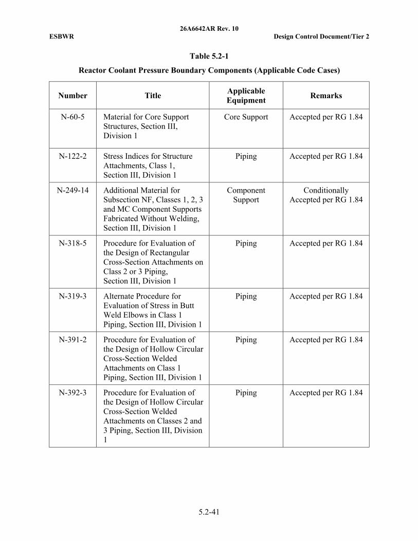
26A6642AR Rev. 10 ESBWR Design Control Document/Tier 2
5.2-41
Table 5.2-1
Reactor Coolant Pressure Boundary Components (Applicable Code Cases)
Number Title Applicable Equipment
Remarks
N-60-5 Material for Core Support Structures, Section III, Division 1
Core Support Accepted per RG 1.84
N-122-2 Stress Indices for Structure Attachments, Class 1, Section III, Division 1
Piping Accepted per RG 1.84
N-249-14 Additional Material for Subsection NF, Classes 1, 2, 3 and MC Component Supports Fabricated Without Welding, Section III, Division 1
Component Support
Conditionally Accepted per RG 1.84
N-318-5 Procedure for Evaluation of the Design of Rectangular Cross-Section Attachments on Class 2 or 3 Piping, Section III, Division 1
Piping Accepted per RG 1.84
N-319-3 Alternate Procedure for Evaluation of Stress in Butt Weld Elbows in Class 1 Piping, Section III, Division 1
Piping Accepted per RG 1.84
N-391-2 Procedure for Evaluation of the Design of Hollow Circular Cross-Section Welded Attachments on Class 1 Piping, Section III, Division 1
Piping Accepted per RG 1.84
N-392-3 Procedure for Evaluation of the Design of Hollow Circular Cross-Section Welded Attachments on Classes 2 and 3 Piping, Section III, Division 1
Piping Accepted per RG 1.84

26A6642AR Rev. 10 ESBWR Design Control Document/Tier 2
5.2-42
Table 5.2-1
Reactor Coolant Pressure Boundary Components (Applicable Code Cases)
Number Title Applicable Equipment
Remarks
N-580-1 Use of Alloy 600 With Columbium Added, Section III, Division 1
Core Support; Reactor Vessel
(nozzles and stub tubes)
Accepted per RG 1.84
N-307-3 Revised Examination Volume for Class 1 Bolting, Table IWB-2500-1, Examination Category B-G-1, when the Examinations are Conducted from the Drilled Hole
RPV Studs Accepted per RG 1.147
N-416-3 Alternative Pressure Test Requirement for Welded or Brazed Repairs, Fabrication Welds or Brazed Joints for Replacement Parts and Piping Subassemblies, or Installation of Replacement Items by Welding or Brazing, Classes 1, 2 and 3
Piping Accepted Per RG 1.147
N-460 Alternative Examination Coverage for Class 1 and 2 Welds
Class 1 & 2 Components and
Piping
Accepted Per RG 1.147
N-613-1 Ultrasonic Examination of Penetration Nozzles in Vessels, Examination Category B-D, Item Nos. B3.10 and B3.90, Reactor Nozzle to Vessel Welds, Figs. IWB 2500-7(a), (b), and (c), Section XI, Division 1
Reactor Vessel Accepted Per RG 1.147
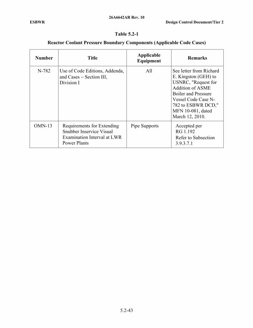
26A6642AR Rev. 10 ESBWR Design Control Document/Tier 2
5.2-43
Table 5.2-1
Reactor Coolant Pressure Boundary Components (Applicable Code Cases)
Number Title Applicable Equipment
Remarks
N-782 Use of Code Editions, Addenda, and Cases − Section III, Division I
All See letter from Richard E. Kingston (GEH) to USNRC, "Request for Addition of ASME Boiler and Pressure Vessel Code Case N-782 to ESBWR DCD," MFN 10-081, dated March 12, 2010.
OMN-13 Requirements for Extending Snubber Inservice Visual Examination Interval at LWR Power Plants
Pipe Supports Accepted per RG 1.192 Refer to Subsection 3.9.3.7.1
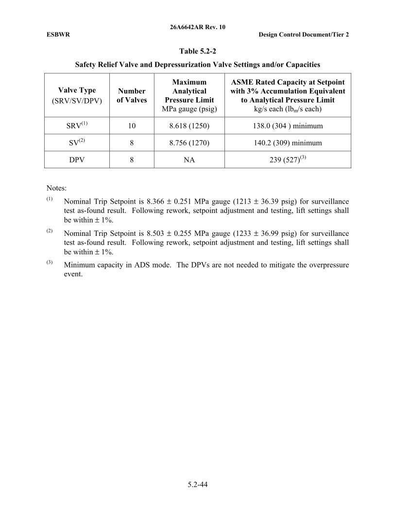
26A6642AR Rev. 10 ESBWR Design Control Document/Tier 2
5.2-44
Table 5.2-2
Safety Relief Valve and Depressurization Valve Settings and/or Capacities
Valve Type
(SRV/SV/DPV) Number of Valves
Maximum Analytical
Pressure Limit MPa gauge (psig)
ASME Rated Capacity at Setpoint with 3% Accumulation Equivalent
to Analytical Pressure Limit kg/s each (lbm/s each)
SRV(1) 10 8.618 (1250) 138.0 (304 ) minimum
SV(2) 8 8.756 (1270) 140.2 (309) minimum
DPV 8 NA 239 (527)(3)
Notes: (1) Nominal Trip Setpoint is 8.366 ± 0.251 MPa gauge (1213 ± 36.39 psig) for surveillance
test as-found result. Following rework, setpoint adjustment and testing, lift settings shall be within ± 1%.
(2) Nominal Trip Setpoint is 8.503 ± 0.255 MPa gauge (1233 ± 36.99 psig) for surveillance test as-found result. Following rework, setpoint adjustment and testing, lift settings shall be within ± 1%.
(3) Minimum capacity in ADS mode. The DPVs are not needed to mitigate the overpressure event.

26A6642AR Rev. 10 ESBWR Design Control Document/Tier 2
5.2-45
Table 5.2-3
(Deleted)
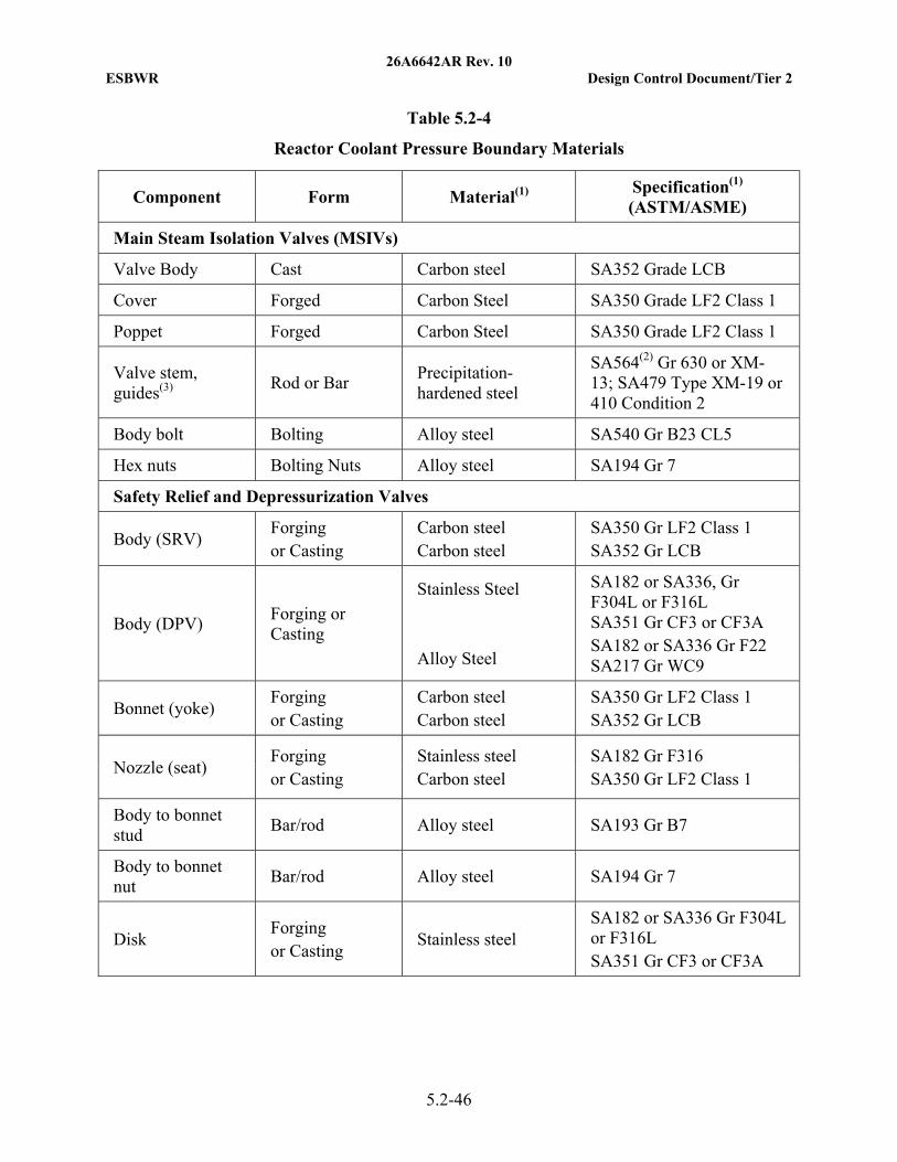
26A6642AR Rev. 10 ESBWR Design Control Document/Tier 2
5.2-46
Table 5.2-4
Reactor Coolant Pressure Boundary Materials
Component Form Material(1) Specification(1) (ASTM/ASME)
Main Steam Isolation Valves (MSIVs)
Valve Body Cast Carbon steel SA352 Grade LCB
Cover Forged Carbon Steel SA350 Grade LF2 Class 1
Poppet Forged Carbon Steel SA350 Grade LF2 Class 1
Valve stem, guides(3)
Rod or Bar Precipitation-hardened steel
SA564(2) Gr 630 or XM-13; SA479 Type XM-19 or 410 Condition 2
Body bolt Bolting Alloy steel SA540 Gr B23 CL5
Hex nuts Bolting Nuts Alloy steel SA194 Gr 7
Safety Relief and Depressurization Valves
Body (SRV) Forging or Casting
Carbon steel Carbon steel
SA350 Gr LF2 Class 1 SA352 Gr LCB
Body (DPV) Forging or Casting
Stainless Steel Alloy Steel
SA182 or SA336, Gr F304L or F316L SA351 Gr CF3 or CF3A SA182 or SA336 Gr F22 SA217 Gr WC9
Bonnet (yoke) Forging or Casting
Carbon steel Carbon steel
SA350 Gr LF2 Class 1 SA352 Gr LCB
Nozzle (seat) Forging or Casting
Stainless steel Carbon steel
SA182 Gr F316 SA350 Gr LF2 Class 1
Body to bonnet stud
Bar/rod Alloy steel SA193 Gr B7
Body to bonnet nut
Bar/rod Alloy steel SA194 Gr 7
Disk Forging or Casting
Stainless steel SA182 or SA336 Gr F304L or F316L SA351 Gr CF3 or CF3A
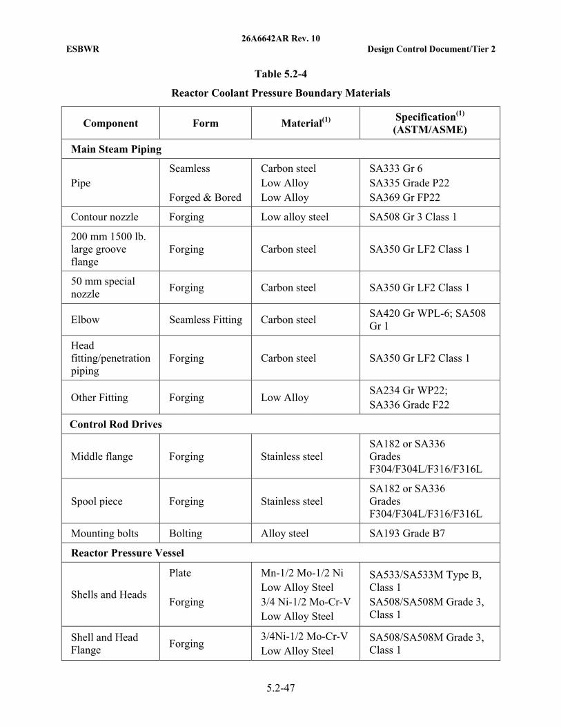
26A6642AR Rev. 10 ESBWR Design Control Document/Tier 2
5.2-47
Table 5.2-4
Reactor Coolant Pressure Boundary Materials
Component Form Material(1) Specification(1) (ASTM/ASME)
Main Steam Piping
Pipe Seamless Forged & Bored
Carbon steel Low Alloy Low Alloy
SA333 Gr 6 SA335 Grade P22 SA369 Gr FP22
Contour nozzle Forging Low alloy steel SA508 Gr 3 Class 1
200 mm 1500 lb. large groove flange
Forging Carbon steel SA350 Gr LF2 Class 1
50 mm special nozzle
Forging Carbon steel SA350 Gr LF2 Class 1
Elbow Seamless Fitting Carbon steel SA420 Gr WPL-6; SA508 Gr 1
Head fitting/penetration piping
Forging Carbon steel SA350 Gr LF2 Class 1
Other Fitting Forging Low Alloy SA234 Gr WP22; SA336 Grade F22
Control Rod Drives
Middle flange Forging Stainless steel SA182 or SA336 Grades F304/F304L/F316/F316L
Spool piece Forging Stainless steel SA182 or SA336 Grades F304/F304L/F316/F316L
Mounting bolts Bolting Alloy steel SA193 Grade B7
Reactor Pressure Vessel
Shells and Heads
Plate Forging
Mn-1/2 Mo-1/2 Ni Low Alloy Steel 3/4 Ni-1/2 Mo-Cr-V Low Alloy Steel
SA533/SA533M Type B, Class 1 SA508/SA508M Grade 3, Class 1
Shell and Head Flange
Forging 3/4Ni-1/2 Mo-Cr-V Low Alloy Steel
SA508/SA508M Grade 3, Class 1
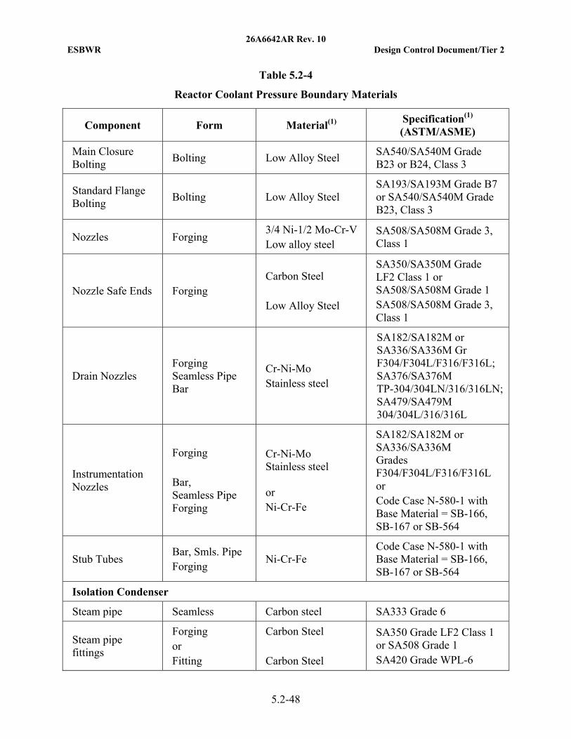
26A6642AR Rev. 10 ESBWR Design Control Document/Tier 2
5.2-48
Table 5.2-4
Reactor Coolant Pressure Boundary Materials
Component Form Material(1) Specification(1) (ASTM/ASME)
Main Closure Bolting
Bolting Low Alloy Steel SA540/SA540M Grade B23 or B24, Class 3
Standard Flange Bolting
Bolting Low Alloy Steel SA193/SA193M Grade B7 or SA540/SA540M Grade B23, Class 3
Nozzles Forging 3/4 Ni-1/2 Mo-Cr-V Low alloy steel
SA508/SA508M Grade 3, Class 1
Nozzle Safe Ends Forging Carbon Steel Low Alloy Steel
SA350/SA350M Grade LF2 Class 1 or SA508/SA508M Grade 1 SA508/SA508M Grade 3, Class 1
Drain Nozzles Forging Seamless Pipe Bar
Cr-Ni-Mo Stainless steel
SA182/SA182M or SA336/SA336M Gr F304/F304L/F316/F316L; SA376/SA376M TP-304/304LN/316/316LN; SA479/SA479M 304/304L/316/316L
Instrumentation Nozzles
Forging Bar, Seamless Pipe Forging
Cr-Ni-Mo Stainless steel or Ni-Cr-Fe
SA182/SA182M or SA336/SA336M Grades F304/F304L/F316/F316L
or Code Case N-580-1 with Base Material = SB-166, SB-167 or SB-564
Stub Tubes Bar, Smls. Pipe Forging
Ni-Cr-Fe Code Case N-580-1 with Base Material = SB-166, SB-167 or SB-564
Isolation Condenser
Steam pipe Seamless Carbon steel SA333 Grade 6
Steam pipe fittings
Forging or Fitting
Carbon Steel Carbon Steel
SA350 Grade LF2 Class 1 or SA508 Grade 1 SA420 Grade WPL-6
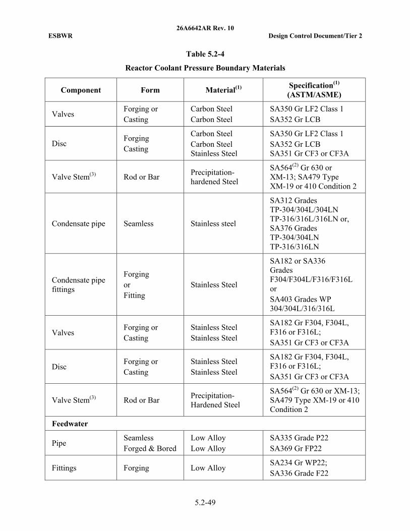
26A6642AR Rev. 10 ESBWR Design Control Document/Tier 2
5.2-49
Table 5.2-4
Reactor Coolant Pressure Boundary Materials
Component Form Material(1) Specification(1) (ASTM/ASME)
Valves Forging or Casting
Carbon Steel Carbon Steel
SA350 Gr LF2 Class 1 SA352 Gr LCB
Disc Forging Casting
Carbon Steel Carbon Steel Stainless Steel
SA350 Gr LF2 Class 1 SA352 Gr LCB SA351 Gr CF3 or CF3A
Valve Stem(3) Rod or Bar Precipitation-hardened Steel
SA564(2) Gr 630 or XM-13; SA479 Type XM-19 or 410 Condition 2
Condensate pipe Seamless Stainless steel
SA312 Grades TP-304/304L/304LN TP-316/316L/316LN or, SA376 Grades TP-304/304LN TP-316/316LN
Condensate pipe fittings
Forging or Fitting
Stainless Steel
SA182 or SA336 Grades F304/F304L/F316/F316L or SA403 Grades WP 304/304L/316/316L
Valves Forging or Casting
Stainless Steel Stainless Steel
SA182 Gr F304, F304L, F316 or F316L; SA351 Gr CF3 or CF3A
Disc Forging or Casting
Stainless Steel Stainless Steel
SA182 Gr F304, F304L, F316 or F316L; SA351 Gr CF3 or CF3A
Valve Stem(3) Rod or Bar Precipitation-Hardened Steel
SA564(2) Gr 630 or XM-13; SA479 Type XM-19 or 410 Condition 2
Feedwater
Pipe Seamless Forged & Bored
Low Alloy Low Alloy
SA335 Grade P22 SA369 Gr FP22
Fittings Forging Low Alloy SA234 Gr WP22; SA336 Grade F22
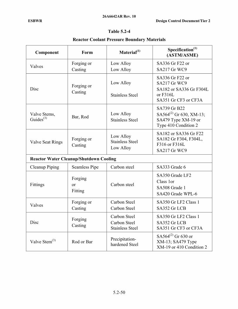
26A6642AR Rev. 10 ESBWR Design Control Document/Tier 2
5.2-50
Table 5.2-4
Reactor Coolant Pressure Boundary Materials
Component Form Material(1) Specification(1) (ASTM/ASME)
Valves Forging or Casting
Low Alloy Low Alloy
SA336 Gr F22 or SA217 Gr WC9
Disc Forging or Casting
Low Alloy Stainless Steel
SA336 Gr F22 or SA217 Gr WC9 SA182 or SA336 Gr F304L or F316L SA351 Gr CF3 or CF3A
Valve Stems, Guides(3)
Bar, Rod Low Alloy Stainless Steel
SA739 Gr B22 SA564(2) Gr 630, XM-13; SA479 Type XM-19 or Type 410 Condition 2
Valve Seat Rings Forging or Casting
Low Alloy Stainless Steel Low Alloy
SA182 or SA336 Gr F22 SA182 Gr F304, F304L, F316 or F316L SA217 Gr WC9
Reactor Water Cleanup/Shutdown Cooling
Cleanup Piping Seamless Pipe Carbon steel SA333 Grade 6
Fittings Forging or Fitting
Carbon steel
SA350 Grade LF2 Class 1or SA508 Grade 1 SA420 Grade WPL-6
Valves Forging or Casting
Carbon Steel Carbon Steel
SA350 Gr LF2 Class 1 SA352 Gr LCB
Disc Forging Casting
Carbon Steel Carbon Steel Stainless Steel
SA350 Gr LF2 Class 1 SA352 Gr LCB SA351 Gr CF3 or CF3A
Valve Stem(3) Rod or Bar Precipitation-hardened Steel
SA564(2) Gr 630 or XM-13; SA479 Type XM-19 or 410 Condition 2
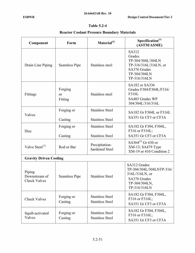
26A6642AR Rev. 10 ESBWR Design Control Document/Tier 2
5.2-51
Table 5.2-4
Reactor Coolant Pressure Boundary Materials
Component Form Material(1) Specification(1) (ASTM/ASME)
Drain Line Piping Seamless Pipe Stainless steel
SA312 Grades TP-304/304L/304LN TP-316/316L/316LN, or SA376 Grades TP-304/304LN TP-316/316LN
Fittings Forging or Fitting
Stainless steel
SA182 or SA336 Grades F304/F304L/F316/ F316L SA403 Grades WP 304/304L/316/316L
Valves Forging or Casting
Stainless Steel Stainless Steel
SA182 Gr F304L or F316L SA351 Gr CF3 or CF3A
Disc Forging or Casting
Stainless Steel Stainless Steel
SA182 Gr F304, F304L, F316 or F316L; SA351 Gr CF3 or CF3A
Valve Stem(3) Rod or Bar Precipitation-hardened Steel
SA564(2) Gr 630 or XM-13; SA479 Type XM-19 or 410 Condition 2
Gravity Driven Cooling
Piping Downstream of Check Valves
Seamless Pipe Stainless Steel
SA312 Grades TP-304/304L/304LNTP-316/316L/316LN, or SA376 Grades TP-304/304LN, TP-316/316LN
Check Valves Forging or Casting
Stainless Steel Stainless Steel
SA182 Gr F304, F304L, F316 or F316L; SA351 Gr CF3 or CF3A
Squib-activated Valves
Forging or Casting
Stainless Steel Stainless Steel
SA182 Gr F304, F304L, F316 or F316L; SA351 Gr CF3 or CF3A
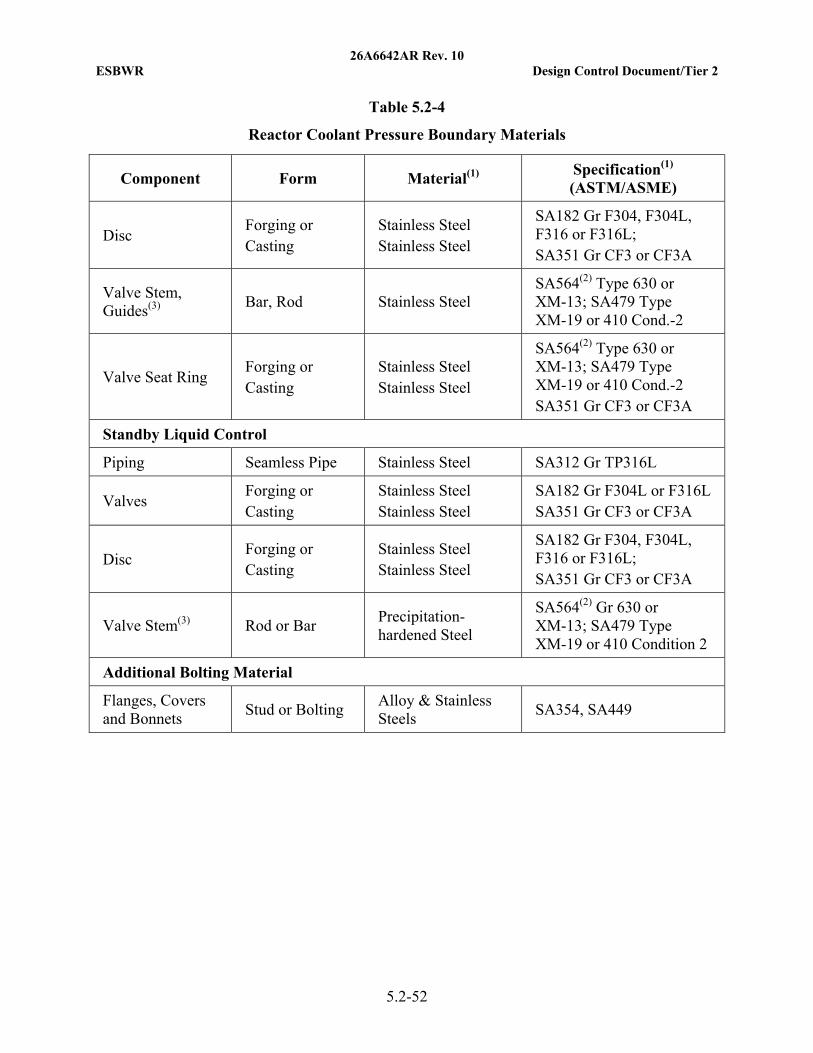
26A6642AR Rev. 10 ESBWR Design Control Document/Tier 2
5.2-52
Table 5.2-4
Reactor Coolant Pressure Boundary Materials
Component Form Material(1) Specification(1) (ASTM/ASME)
Disc Forging or Casting
Stainless Steel Stainless Steel
SA182 Gr F304, F304L, F316 or F316L; SA351 Gr CF3 or CF3A
Valve Stem, Guides(3)
Bar, Rod Stainless Steel SA564(2) Type 630 or XM-13; SA479 Type XM-19 or 410 Cond.-2
Valve Seat Ring Forging or Casting
Stainless Steel Stainless Steel
SA564(2) Type 630 or XM-13; SA479 Type XM-19 or 410 Cond.-2 SA351 Gr CF3 or CF3A
Standby Liquid Control
Piping Seamless Pipe Stainless Steel SA312 Gr TP316L
Valves Forging or Casting
Stainless Steel Stainless Steel
SA182 Gr F304L or F316L SA351 Gr CF3 or CF3A
Disc Forging or Casting
Stainless Steel Stainless Steel
SA182 Gr F304, F304L, F316 or F316L; SA351 Gr CF3 or CF3A
Valve Stem(3) Rod or Bar Precipitation-hardened Steel
SA564(2) Gr 630 or XM-13; SA479 Type XM-19 or 410 Condition 2
Additional Bolting Material
Flanges, Covers and Bonnets
Stud or Bolting Alloy & Stainless Steels
SA354, SA449
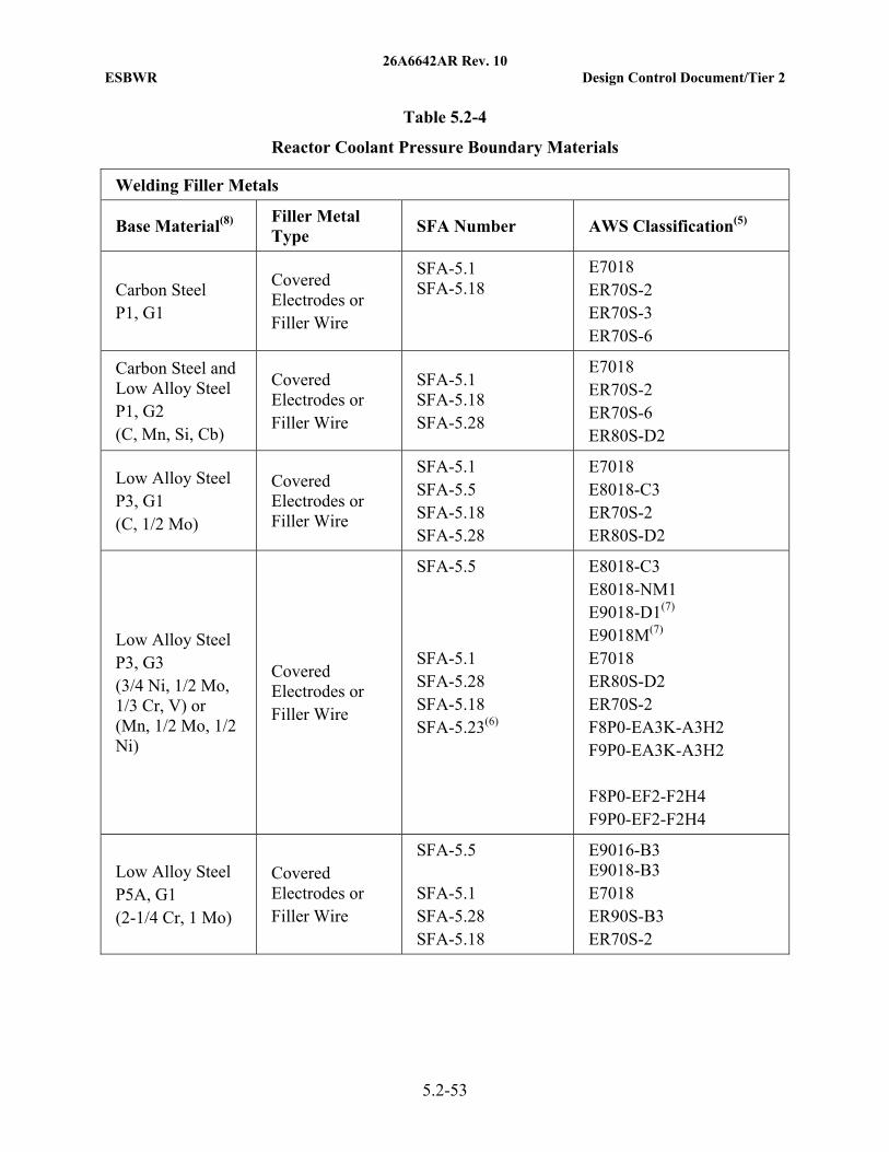
26A6642AR Rev. 10 ESBWR Design Control Document/Tier 2
5.2-53
Table 5.2-4
Reactor Coolant Pressure Boundary Materials
Welding Filler Metals
Base Material(8) Filler Metal Type
SFA Number AWS Classification(5)
Carbon Steel P1, G1
Covered Electrodes or Filler Wire
SFA-5.1 SFA-5.18
E7018 ER70S-2 ER70S-3 ER70S-6
Carbon Steel and Low Alloy Steel P1, G2 (C, Mn, Si, Cb)
Covered Electrodes or Filler Wire
SFA-5.1 SFA-5.18 SFA-5.28
E7018 ER70S-2 ER70S-6 ER80S-D2
Low Alloy Steel P3, G1 (C, 1/2 Mo)
Covered Electrodes or Filler Wire
SFA-5.1 SFA-5.5 SFA-5.18 SFA-5.28
E7018 E8018-C3 ER70S-2 ER80S-D2
Low Alloy Steel P3, G3 (3/4 Ni, 1/2 Mo, 1/3 Cr, V) or (Mn, 1/2 Mo, 1/2 Ni)
Covered Electrodes or Filler Wire
SFA-5.5 SFA-5.1 SFA-5.28 SFA-5.18 SFA-5.23(6)
E8018-C3 E8018-NM1 E9018-D1(7) E9018M(7) E7018 ER80S-D2 ER70S-2 F8P0-EA3K-A3H2 F9P0-EA3K-A3H2 F8P0-EF2-F2H4 F9P0-EF2-F2H4
Low Alloy Steel P5A, G1 (2-1/4 Cr, 1 Mo)
Covered Electrodes or Filler Wire
SFA-5.5 SFA-5.1 SFA-5.28 SFA-5.18
E9016-B3 E9018-B3 E7018 ER90S-B3 ER70S-2
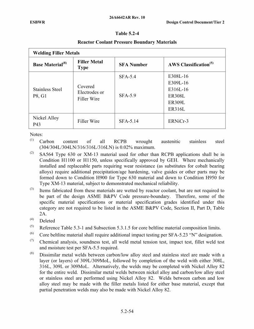
26A6642AR Rev. 10 ESBWR Design Control Document/Tier 2
5.2-54
Table 5.2-4
Reactor Coolant Pressure Boundary Materials
Welding Filler Metals
Base Material(8) Filler Metal Type
SFA Number AWS Classification(5)
Stainless Steel P8, G1
Covered Electrodes or Filler Wire
SFA-5.4 SFA-5.9
E308L-16 E309L-16 E316L-16 ER308L ER309L ER316L
Nickel Alloy P43
Filler Wire SFA-5.14 ERNiCr-3
Notes: (1) Carbon content of all RCPB wrought austenitic stainless steel
(304/304L/304LN/316/316L/316LN) is 0.02% maximum. (2) SA564 Type 630 or XM-13 material used for other than RCPB applications shall be in
Condition H1100 or H1150, unless specifically approved by GEH. Where mechanically installed and replaceable parts requiring wear resistance (as substitutes for cobalt bearing alloys) require additional precipitation/age hardening, valve guides or other parts may be formed down to Condition H900 for Type 630 material and down to Condition H950 for Type XM-13 material, subject to demonstrated mechanical reliability.
(3) Items fabricated from these materials are wetted by reactor coolant, but are not required to be part of the design ASME B&PV Code pressure-boundary. Therefore, some of the specific material specifications or material specification grades identified under this category are not required to be listed in the ASME B&PV Code, Section II, Part D, Table 2A.
(4) Deleted (5) Reference Table 5.3-1 and Subsection 5.3.1.5 for core beltline material composition limits. (6) Core beltline material shall require additional impact testing per SFA-5.23 “N” designation. (7) Chemical analysis, soundness test, all weld metal tension test, impact test, fillet weld test
and moisture test per SFA-5.5 required. (8) Dissimilar metal welds between carbon/low alloy steel and stainless steel are made with a
layer (or layers) of 309L/309MoL, followed by completion of the weld with either 308L, 316L, 309L or 309MoL. Alternatively, the welds may be completed with Nickel Alloy 82 for the entire weld. Dissimilar metal welds between nickel alloy and carbon/low alloy steel or stainless steel are performed using Nickel Alloy 82. Welds between carbon and low alloy steel may be made with the filler metals listed for either base material, except that partial penetration welds may also be made with Nickel Alloy 82.
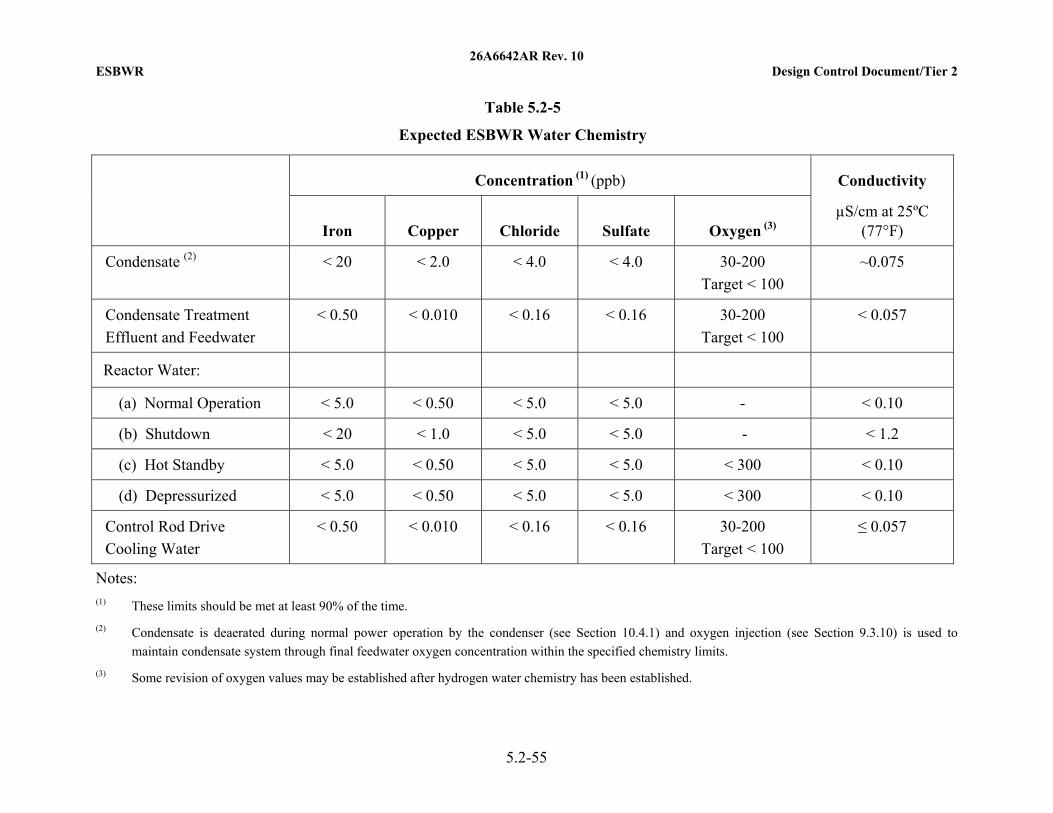
26A6642AR Rev. 10 ESBWR Design Control Document/Tier 2
5.2-55
Table 5.2-5
Expected ESBWR Water Chemistry
Concentration (1) (ppb) Conductivity
Iron Copper Chloride Sulfate Oxygen (3) µS/cm at 25ºC
(77°F)
Condensate (2) < 20 < 2.0 < 4.0 < 4.0 30-200
Target < 100
~0.075
Condensate Treatment
Effluent and Feedwater
< 0.50 < 0.010 < 0.16 < 0.16 30-200
Target < 100
< 0.057
Reactor Water:
(a) Normal Operation < 5.0 < 0.50 < 5.0 < 5.0 - < 0.10
(b) Shutdown < 20 < 1.0 < 5.0 < 5.0 - < 1.2
(c) Hot Standby < 5.0 < 0.50 < 5.0 < 5.0 < 300 < 0.10
(d) Depressurized < 5.0 < 0.50 < 5.0 < 5.0 < 300 < 0.10
Control Rod Drive
Cooling Water
< 0.50 < 0.010 < 0.16 < 0.16 30-200
Target < 100
≤ 0.057
Notes: (1) These limits should be met at least 90% of the time.
(2) Condensate is deaerated during normal power operation by the condenser (see Section 10.4.1) and oxygen injection (see Section 9.3.10) is used to
maintain condensate system through final feedwater oxygen concentration within the specified chemistry limits.
(3) Some revision of oxygen values may be established after hydrogen water chemistry has been established.
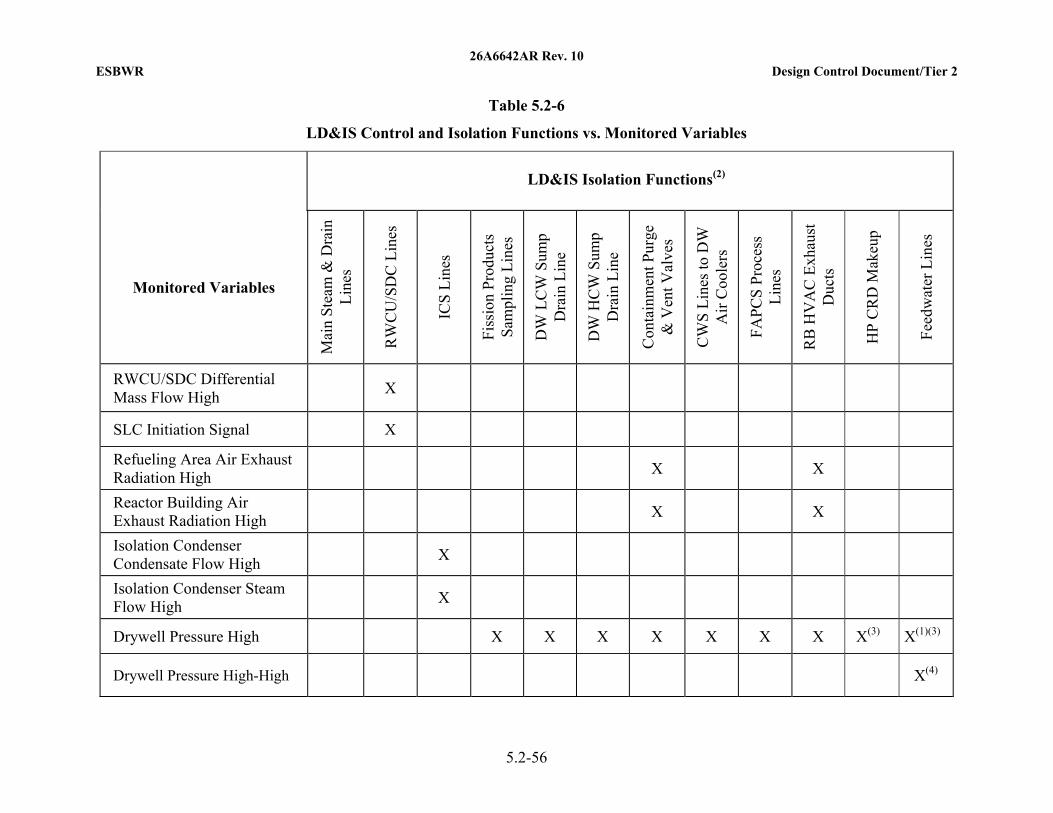
26A6642AR Rev. 10 ESBWR Design Control Document/Tier 2
5.2-56
Table 5.2-6
LD&IS Control and Isolation Functions vs. Monitored Variables
LD&IS Isolation Functions(2)
Monitored Variables
Mai
n S
team
& D
rain
L
ines
RW
CU
/SD
C L
ines
ICS
Lin
es
Fis
sion
Pro
duct
s S
ampl
ing
Lin
es
DW
LC
W S
ump
Dra
in L
ine
DW
HC
W S
ump
Dra
in L
ine
Con
tain
men
t Pur
ge
& V
ent V
alve
s
CW
S L
ines
to D
W
Air
Coo
lers
FA
PC
S P
roce
ss
Lin
es
RB
HV
AC
Exh
aust
D
ucts
HP
CR
D M
akeu
p
Fee
dwat
er L
ines
RWCU/SDC Differential Mass Flow High
X
SLC Initiation Signal X
Refueling Area Air Exhaust Radiation High
X X
Reactor Building Air Exhaust Radiation High
X X
Isolation Condenser Condensate Flow High
X
Isolation Condenser Steam Flow High
X
Drywell Pressure High X X X X X X X X(3) X(1)(3)
Drywell Pressure High-High
X(4)
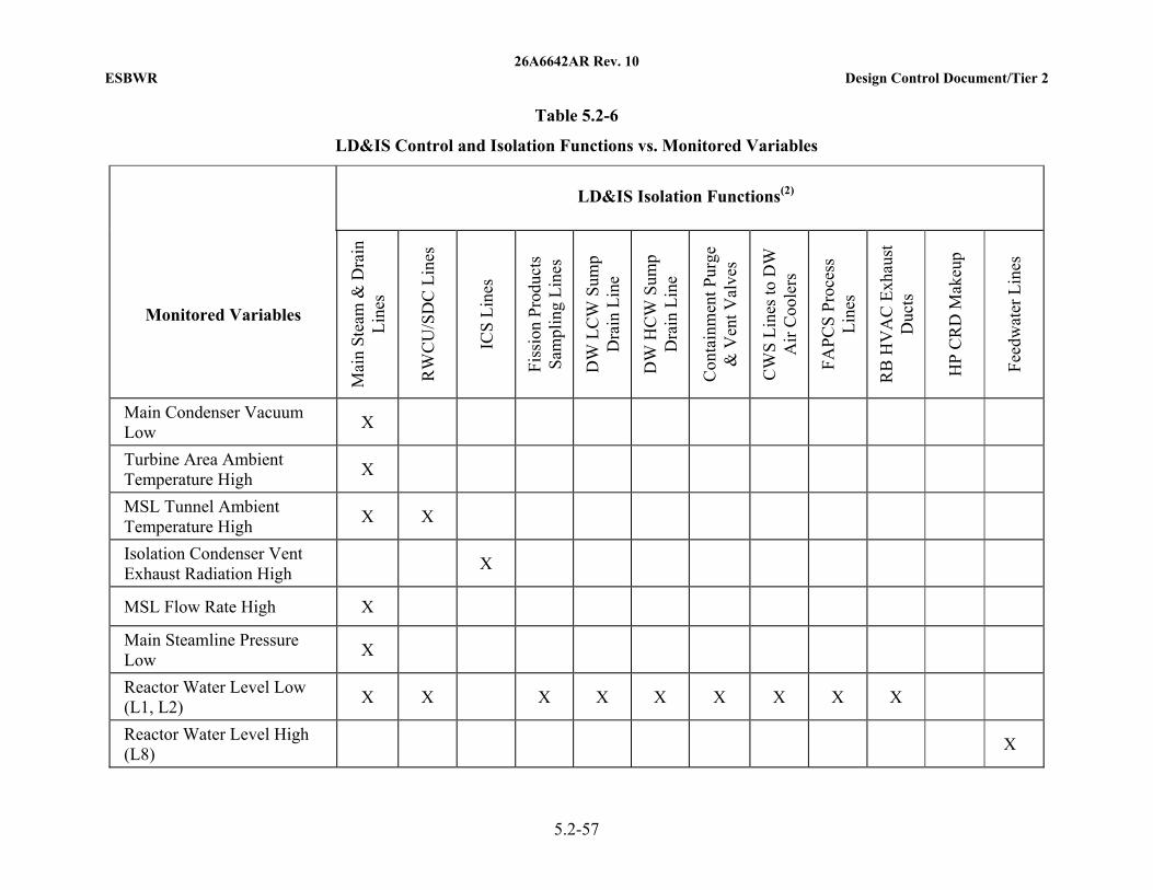
26A6642AR Rev. 10 ESBWR Design Control Document/Tier 2
5.2-57
Table 5.2-6
LD&IS Control and Isolation Functions vs. Monitored Variables
LD&IS Isolation Functions(2)
Monitored Variables
Mai
n S
team
& D
rain
L
ines
RW
CU
/SD
C L
ines
ICS
Lin
es
Fis
sion
Pro
duct
s S
ampl
ing
Lin
es
DW
LC
W S
ump
Dra
in L
ine
DW
HC
W S
ump
Dra
in L
ine
Con
tain
men
t Pur
ge
& V
ent V
alve
s
CW
S L
ines
to D
W
Air
Coo
lers
FA
PC
S P
roce
ss
Lin
es
RB
HV
AC
Exh
aust
D
ucts
HP
CR
D M
akeu
p
Fee
dwat
er L
ines
Main Condenser Vacuum Low
X
Turbine Area Ambient Temperature High
X
MSL Tunnel Ambient Temperature High
X X
Isolation Condenser Vent Exhaust Radiation High
X
MSL Flow Rate High X
Main Steamline Pressure Low
X
Reactor Water Level Low (L1, L2)
X X X X X X X X X
Reactor Water Level High (L8)
X
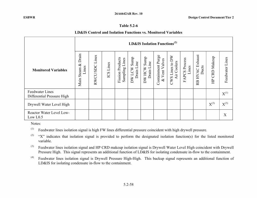
26A6642AR Rev. 10 ESBWR Design Control Document/Tier 2
5.2-58
Table 5.2-6
LD&IS Control and Isolation Functions vs. Monitored Variables
LD&IS Isolation Functions(2)
Monitored Variables
Mai
n S
team
& D
rain
L
ines
RW
CU
/SD
C L
ines
ICS
Lin
es
Fis
sion
Pro
duct
s S
ampl
ing
Lin
es
DW
LC
W S
ump
Dra
in L
ine
DW
HC
W S
ump
Dra
in L
ine
Con
tain
men
t Pur
ge
& V
ent V
alve
s
CW
S L
ines
to D
W
Air
Coo
lers
FA
PC
S P
roce
ss
Lin
es
RB
HV
AC
Exh
aust
D
ucts
HP
CR
D M
akeu
p
Fee
dwat
er L
ines
Feedwater Lines Differential Pressure High
X(1)
Drywell Water Level High X(3) X(3)
Reactor Water Level Low-Low L0.5
X
Notes: (1) Feedwater lines isolation signal is high FW lines differential pressure coincident with high drywell pressure. (2) “X” indicates that isolation signal is provided to perform the designated isolation function(s) for the listed monitored
variable. (3) Feedwater lines isolation signal and HP CRD makeup isolation signal is Drywell Water Level High coincident with Drywell
Pressure High. This signal represents an additional function of LD&IS for isolating condensate in-flow to the containment. (4) Feedwater lines isolation signal is Drywell Pressure High-High. This backup signal represents an additional function of
LD&IS for isolating condensate in-flow to the containment.

26A6642AR Rev. 10 ESBWR Design Control Document/Tier 2
5.2-59
Table 5.2-7
Leakage Sources vs. Monitored Variables
Leakage Sources
Monitored Variables (2)(3)
Loc
atio
n (1
)
Mai
n S
team
line
s
Isol
atio
n C
onde
nser
S
team
line
s Is
olat
ion
Con
dens
er
Con
dens
ate
Lin
es
CW
S L
ines
FA
PC
S L
ines
RW
CU
/SD
C
Lin
es
Fee
dwat
er L
ines
GD
CS
Wat
er
Rea
ctor
Ves
sel
Hea
d S
eal
Mis
c.
Lea
ks
I O I O I O I O I O I O I O I O I O I O
Inter-System Leakage Radiation High
X
RWCU/SDC Differential Mass Flow High
X
Equip. Areas Differential Temperature High
X X
MSL Tunnel or Turbine Building Area Ambient Temperature High
X X X X
MSL Flow High X X
Isolation Condenser Steamline Flow High
X X
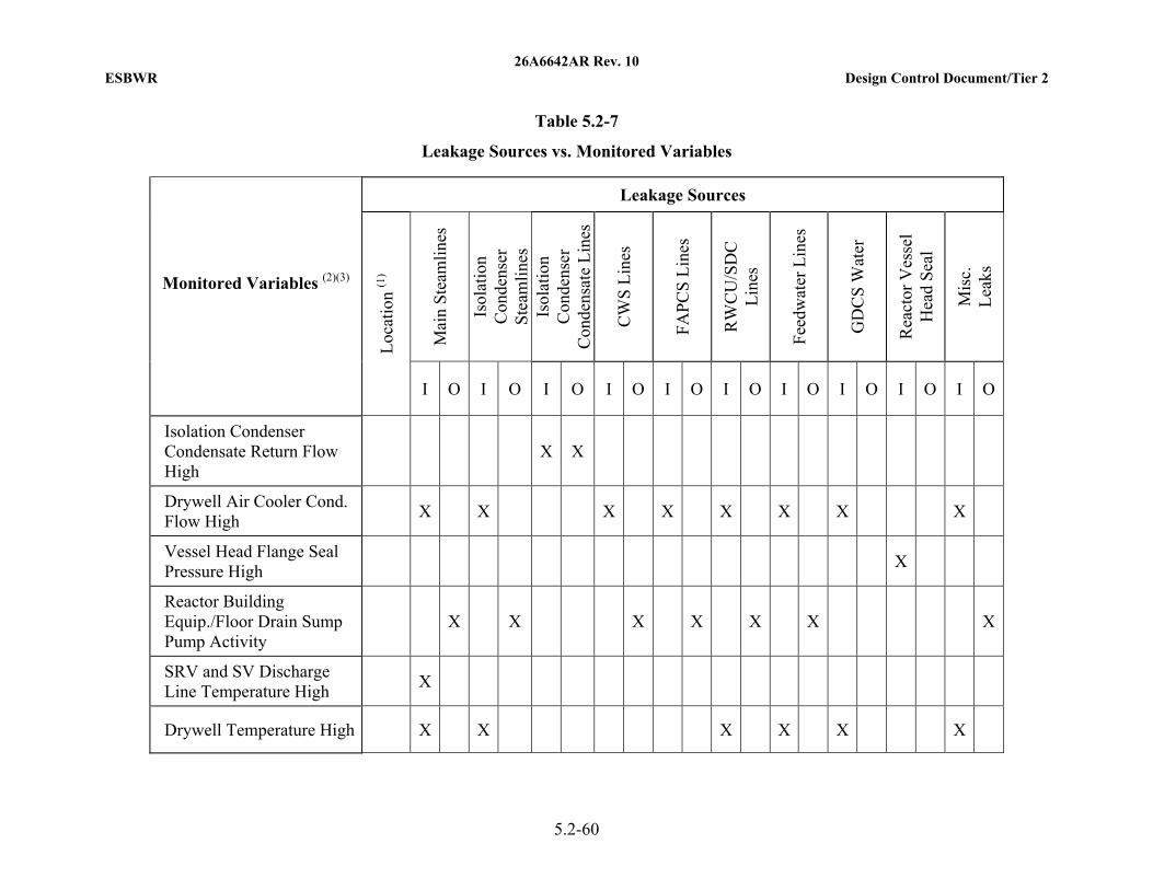
26A6642AR Rev. 10 ESBWR Design Control Document/Tier 2
5.2-60
Table 5.2-7
Leakage Sources vs. Monitored Variables
Leakage Sources
Monitored Variables (2)(3)
Loc
atio
n (1
)
Mai
n S
team
line
s
Isol
atio
n C
onde
nser
S
team
line
s Is
olat
ion
Con
dens
er
Con
dens
ate
Lin
es
CW
S L
ines
FA
PC
S L
ines
RW
CU
/SD
C
Lin
es
Fee
dwat
er L
ines
GD
CS
Wat
er
Rea
ctor
Ves
sel
Hea
d S
eal
Mis
c.
Lea
ks
I O I O I O I O I O I O I O I O I O I O
Isolation Condenser Condensate Return Flow High
X X
Drywell Air Cooler Cond. Flow High
X X X X X X X X
Vessel Head Flange Seal Pressure High
X
Reactor Building Equip./Floor Drain Sump Pump Activity
X X X X X X X
SRV and SV Discharge Line Temperature High
X
Drywell Temperature High X X X X X X
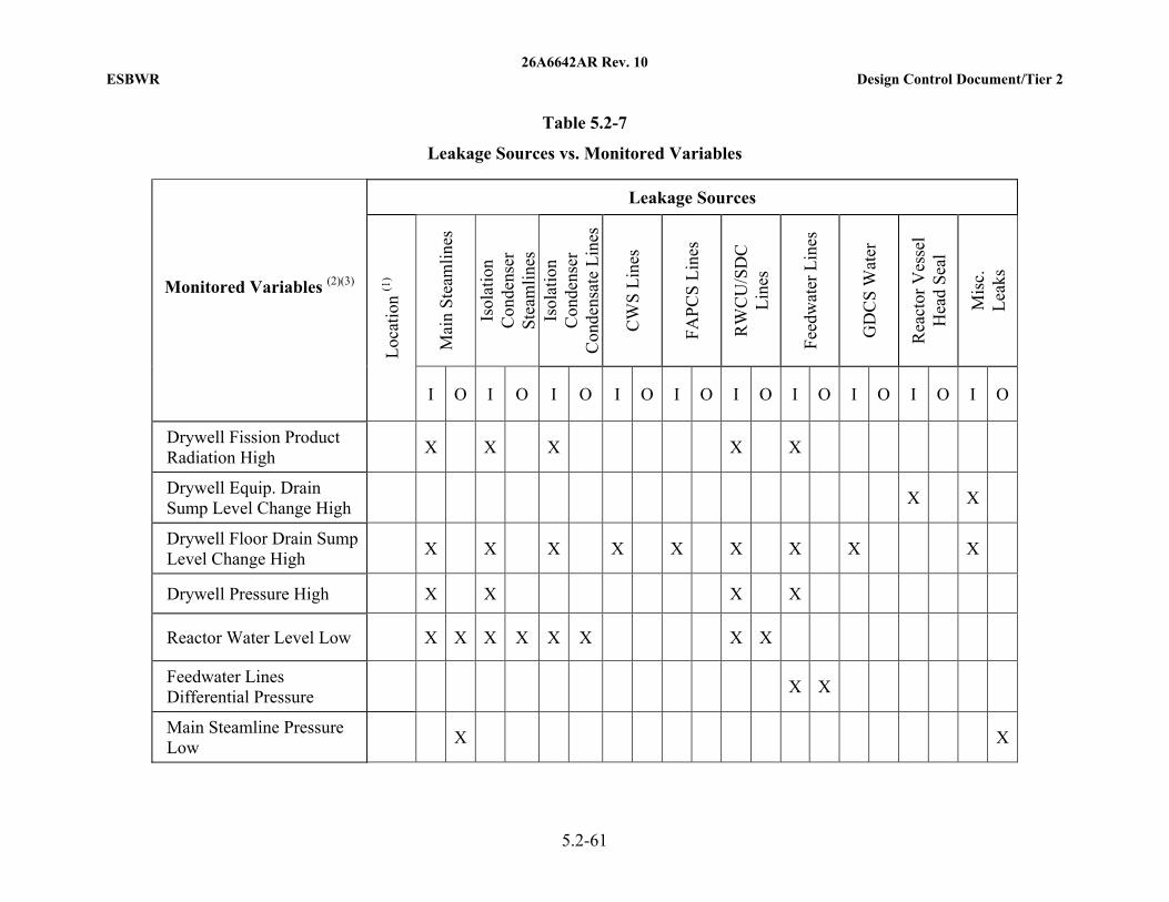
26A6642AR Rev. 10 ESBWR Design Control Document/Tier 2
5.2-61
Table 5.2-7
Leakage Sources vs. Monitored Variables
Leakage Sources
Monitored Variables (2)(3)
Loc
atio
n (1
)
Mai
n S
team
line
s
Isol
atio
n C
onde
nser
S
team
line
s Is
olat
ion
Con
dens
er
Con
dens
ate
Lin
es
CW
S L
ines
FA
PC
S L
ines
RW
CU
/SD
C
Lin
es
Fee
dwat
er L
ines
GD
CS
Wat
er
Rea
ctor
Ves
sel
Hea
d S
eal
Mis
c.
Lea
ks
I O I O I O I O I O I O I O I O I O I O
Drywell Fission Product Radiation High
X X X X X
Drywell Equip. Drain Sump Level Change High
X X
Drywell Floor Drain Sump Level Change High
X X X X X X X X X
Drywell Pressure High X X X X
Reactor Water Level Low X X X X X X X X
Feedwater Lines Differential Pressure
X X
Main Steamline Pressure Low
X X
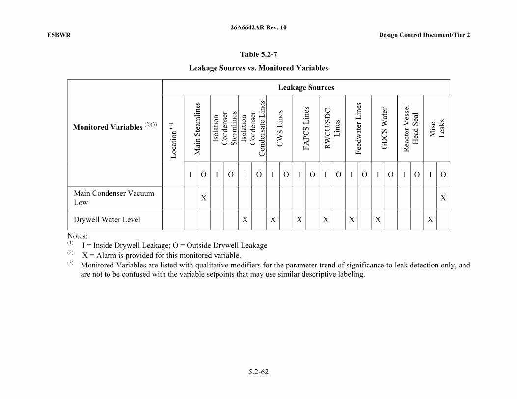
26A6642AR Rev. 10 ESBWR Design Control Document/Tier 2
5.2-62
Table 5.2-7
Leakage Sources vs. Monitored Variables
Leakage Sources
Monitored Variables (2)(3)
Loc
atio
n (1
)
Mai
n S
team
line
s
Isol
atio
n C
onde
nser
S
team
line
s Is
olat
ion
Con
dens
er
Con
dens
ate
Lin
es
CW
S L
ines
FA
PC
S L
ines
RW
CU
/SD
C
Lin
es
Fee
dwat
er L
ines
GD
CS
Wat
er
Rea
ctor
Ves
sel
Hea
d S
eal
Mis
c.
Lea
ks
I O I O I O I O I O I O I O I O I O I O
Main Condenser Vacuum Low
X X
Drywell Water Level X X X X X X X
Notes: (1) I = Inside Drywell Leakage; O = Outside Drywell Leakage (2) X = Alarm is provided for this monitored variable. (3) Monitored Variables are listed with qualitative modifiers for the parameter trend of significance to leak detection only, and
are not to be confused with the variable setpoints that may use similar descriptive labeling.
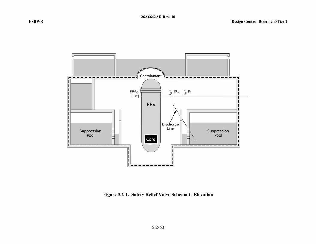
26A6642AR Rev. 10 ESBWR Design Control Document/Tier 2
5.2-63
Figure 5.2-1. Safety Relief Valve Schematic Elevation
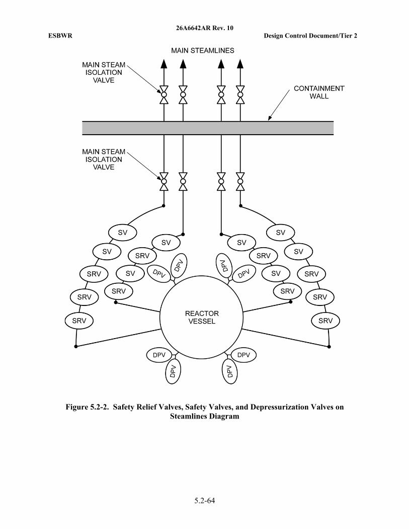
26A6642AR Rev. 10 ESBWR Design Control Document/Tier 2
5.2-64
Figure 5.2-2. Safety Relief Valves, Safety Valves, and Depressurization Valves on Steamlines Diagram
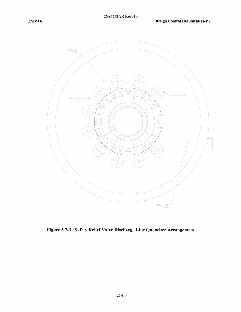
26A6642AR Rev. 10 ESBWR Design Control Document/Tier 2
5.2-65
Figure 5.2-3. Safety Relief Valve Discharge Line Quencher Arrangement
26A6642AR Rev. 10 ESBWR Design Control Document/Tier 2
5.3-1
5.3 REACTOR VESSEL
5.3.1 Reactor Vessel Materials
The ESBWR meets the requirements of:
• General Design Criteria (GDC) 1 and 30, as they relate to quality standards for design, fabrication, erection, and testing of structures, systems, and components;
• GDC 4, as it relates to compatibility of components with environmental conditions;
• GDC 14, as it relates to prevention of rapidly propagating fractures of the reactor coolant pressure boundary (RCPB);
• GDC 31, as it relates to material fracture toughness;
• GDC 32, as it relates to the requirements for a materials surveillance program;
• 10 CFR 50.55a as it relates to quality standards for design and determination and monitoring of fracture toughness;
• 10 CFR 50.60, “Acceptance criteria for fracture prevention measures for light water nuclear power reactors for normal operation”, as it relates to RCPB fracture toughness and material surveillance requirements of 10 CFR 50, Appendix G and Appendix H;
• 10 CFR 50, Appendix B, Criterion XIII, as it relates to onsite material cleaning control;
• 10 CFR 50, Appendix G, as it relates to materials testing and acceptance criteria for fracture toughness; and
• 10 CFR 50, Appendix H, as it relates to the determination and monitoring of fracture toughness.
The specific criteria which meet the relevant requirements are as presented in the following subsections.
5.3.1.1 Materials Specifications
The materials used in the reactor pressure vessel (RPV) and appurtenances are shown in Table 5.2-4, together with the applicable specifications.
The RPV materials shall comply with the provisions of ASME B&PV Code Section III, and shall also meet the requirements of ASME B&PV Code Section II materials and 10 CFR 50, Appendix G. The RPV materials also meet the additional requirements as explained in the following subsections.
These materials provide adequate strength, fracture toughness, fabricability, and compatibility with the boiling water reactor (BWR) environment. Their suitability has been demonstrated by long-term successful operating experience in reactor service.
5.3.1.2 Special Procedures Used for Manufacturing and Fabrication
The RPV is constructed primarily from low alloy, high strength steel plate and forgings. Plates are ordered to ASME SA-533, Type B, Class 1, and forgings to ASME SA-508, Grade 3, Class 1. These materials are melted to fine grain practice and are supplied in the quenched and
26A6642AR Rev. 10 ESBWR Design Control Document/Tier 2
5.3-2
tempered condition. Further restrictions include a requirement for vacuum degassing to lower the hydrogen level and improve the cleanliness of the low alloy steels. Specified limits for materials used in the core beltline region are presented in Table 5.3-1.
Studs, nuts, and washers for the main closure flange have special material controls as presented in Table 5.3-1. Welding electrodes for low alloy steel are low hydrogen type ordered to ASME SFA-5.5, and weld filler metal to SFA-5.23 and SFA-5.28.
All plate, forgings, and bolting are 100% ultrasonically tested and surface examined by magnetic particle methods or liquid penetrant methods as required by ASME B&PV Code Section III, Division 1.
Fracture toughness properties of materials are also measured and controlled in accordance with ASME B&PV Code Section III, Division 1.
All fabrication of the RPV is performed in accordance with GEH approved drawings, fabrication procedures, and test procedures. The shells and vessel heads are made from formed plates or forgings, whereas flanges and nozzles are made from forgings. Welding performed to join these vessel components is in accordance with procedures qualified per ASME B&PV Code Section III and IX requirements. Weld test samples are required for each procedure used on major vessel full penetration welds. Tensile and impact tests are performed to determine the properties of the base metal, heat-affected zone (HAZ), and weld metal.
Gas Tungsten Arc Welding, Gas Metal Arc Welding, Shielded Metal Arc Welding, and Submerged Arc Welding processes may be employed. Electroslag welding is not used except for cladding. Preheat and interpass temperatures employed for welding of low alloy steel meet or exceed the values given in ASME B&PV Code Section III, Appendix D. Post-weld heat treatment of all low alloy welds is performed in accordance with ASME B&PV Code Section III, NB-4620 (see Table 5.3-1).
Volumetric examination and surface examination are performed on all pressure-retaining welds as required by ASME B&PV Code Section III, NB-5300. In addition, all pressure-retaining welds are given a supplemental ultrasonic pre-service examination in accordance with ASME B&PV Code Section XI.
The materials, fabrication procedures, and testing methods used in the construction of the ESBWR RPV meet or exceed requirements of ASME B&PV Code Section III, Class 1 vessels.
5.3.1.3 Special Methods for Nondestructive Examination
The materials and welds on the RPV are examined in accordance with methods prescribed and meet the acceptance requirements specified by ASME B&PV Code Section III. The pressure-retaining welds are volumetrically examined. In addition, the pressure-retaining welds are ultrasonically examined using acceptance standards that are equivalent or more restrictive than required by ASME B&PV Code Section XI. The ultrasonic examination method, including calibration, instrumentation, scanning sensitivity, and coverage, is based on the requirements imposed by ASME B&PV Code Section XI, Appendix I.
26A6642AR Rev. 10 ESBWR Design Control Document/Tier 2
5.3-3
5.3.1.4 Special Controls for Ferritic and Austenitic Stainless Steels
RG 1.31: Control of Stainless Steel Welding
Controls on stainless steel welding are discussed in Subsection 5.2.3.4.2. Consistent with Generic Letter 88-01 and NUREG-0313 Revision 2, control of weld filler metal ferrite content is described in Subsection 5.2.3.4.
RG 1.34: Control of Electroslag Weld Properties
The requirements of this regulatory guide are not applicable to the ESBWR vessel, because electroslag welding is not employed in structural welds of low alloy steel. Electroslag welding is not used except for cladding.
RG 1.43: Control of Stainless Steel Weld Cladding of Low Alloy Steel Components
RG 1.43 is concerned with cracking of low alloy steels underneath stainless steel weld deposited cladding. The requirements of this regulatory guide are not applicable to the ESBWR vessel because the RPV is constructed from low alloy steel forgings or plates conforming to SA-508, Grade 3 or SA-533, Type B, which are produced to fine grain practice. Therefore, underclad cracking is not a concern, and the requirements of this regulatory guide are not applicable.
RG 1.44: Control of the Use of Sensitized Stainless Steel
Sensitization of stainless steel is controlled by the use of service proven low carbon materials and by use of appropriate design and processing steps, including solution heat treatment, control of welding heat input, control of heat treatment during fabrication, and control of stresses. As more completely described in Subsection 5.2.3.4.1, these controls conform to the guidance of Generic Letter 88-01 and NUREG-0313 Revision 2.
RG 1.50: Control of Preheat Temperature For Welding Low Alloy Steel
RG 1.50 delineates preheat temperature control requirements and welding procedure qualifications supplementing those in ASME B&PV Code Sections III and IX. Except as noted below, RG 1.50 is followed.
Preheat temperature employed for welding of low alloy steel meets or exceeds the recommendations of ASME B&PV Code Section III, Appendix D. Components are either held for an extended time at preheat temperature to assure removal of hydrogen, or preheat is maintained until post-weld heat treatment. The minimum preheat and maximum interpass temperatures for welding the ESBWR reactor vessel are specified and monitored, and the welding procedures are qualified using the minimum preheat temperatures.
All pressure-retaining welds are nondestructively examined by volumetric methods.
RG 1.71: Welder Qualification for Areas of Limited Accessibility
Qualification for areas of limited accessibility is discussed under RG 1.71 in Subsection 5.2.3.4.2 of this report.
RG 1.99: Effects of Residual Elements on Predicted Radiation Damage to Reactor Pressure Vessel Materials
Predictions for changes in transition temperature and upper shelf energy are made in accordance with the requirements of RG 1.99.
26A6642AR Rev. 10 ESBWR Design Control Document/Tier 2
5.3-4
RG 1.37: Quality Assurance Requirements for Cleaning of Fluid Systems and Associated Components of Water-Cooled Nuclear Power Plants
The cleaning of systems and components on the site during and at the completion of construction is accomplished to written procedures, which ensures both cleanliness and that the components are not exposed to materials or practices which may degrade their performance. For components containing stainless steel, the procedures shall comply with RG 1.37. The procedures prohibit contact with low melting point compounds, substances which are known to cause stress corrosion cracking or which can release, in any manner, substances that can cause such problems. In addition, there are controls placed on the use of grinding wheels and wire brushes, which assures that they cannot introduce degrading materials either through prior usage or through their materials of construction. In this context, degradation includes stress corrosion cracking. Controls also control introduction of unnecessary dirt and require control of dirt producing processes such as welding or grinding including prompt cleaning.
5.3.1.5 Fracture Toughness
Compliance with 10 CFR 50, Appendix G
Appendix G of 10 CFR 50 is interpreted for Class 1 primary coolant pressure boundary components of the ESBWR design and complied with as discussed in Methods of Compliance below and Subsection 5.3.2. The specific temperature/pressure limits for the operation of the reactor (Figures 5.3-1 and 5.3-2) are based on 10 CFR 50 Appendix G, Paragraph IV, A.2. The COL Applicant, in accordance with the Technical Specification (Chapter 16, Subsection 5.6.4), will furnish either bounding pressure and temperature curves as part of the technical specification or as part of a Pressure and Temperature Limits Report submittal for NRC review.
Methods of Compliance
The following items are the interpretations and methods used to comply with 10 CFR 50, Appendix G:
• Material Test Coupons and Test Specimens (Appendix G III-A)
Test coupons are removed from the location in each product form as specified in NB-2220 of ASME B&PV Code Section III. The heat treatment of the test coupons is performed in accordance with NB-2210.
Separate test coupons produced in accordance with NB-2223.3 may be used for forgings.
• Location and Orientation of Test Specimens (Appendix G III-A)
The test specimens are located and oriented in accordance with ASME B&PV Code Section III, NB-2322. Charpy V-notch impact specimens for testing of plate will be oriented normal to the principal rolling direction (not in the thickness direction). For forged material other than bolting and bars the Charpy V-notch impact specimens will be oriented normal to the principal direction in which the material was worked. Axial specimens are used for bolting and bars.
In regard to 10 CFR 50 Appendix H, the surveillance test material is selected on the basis of the requirements of ASTM E185-82 and RG 1.99 to provide a conservative adjusted reference temperature for the beltline materials. The weld test plate for the surveillance
26A6642AR Rev. 10 ESBWR Design Control Document/Tier 2
5.3-5
program specimens has the principal working direction parallel to the weld seam to assure that HAZ specimens are normal to the principal working direction.
• Records and Procedures for Impact Testing (Appendix G III-C)
Preparation of impact testing procedures, calibration of test equipment, and retention of the records of these functions and test data comply with the requirements of ASME B&PV Code Section III. Personnel conducting impact testing are qualified by experience, training or qualification testing that demonstrates competence to perform tests in accordance with the testing procedure.
• Charpy Curves for the RPV Beltline (Appendix G III-A and G IV-A.1)
A full transverse Charpy curve is determined for all heats of base material and weld metal used in the core beltline region with a minimum of three (3) specimens tested in the upper shelf region (>95% shear). The minimum initial upper shelf energy level for base material and weld metal in the beltline region meets or exceeds 102 J (75 ft-lbf), and is predicted to maintain a Charpy upper shelf energy of greater than 68 J (50 ft-lbf) throughout the life of the vessel, as required by 10 CFR 50, Appendix G IV-A.1.
In regard to 10 CFR 50, Appendix G III-A, separate, unirradiated baseline specimens per ASTM E-185, Paragraph 6.3.1, are used to determine the transition temperature curve of the core beltline base material, HAZ, and weld metal.
• Bolting Material
All bolting material exceeding 25.4 mm (1 inch) diameter has special material requirements as presented in Table 5.3-1.
• Fracture Toughness Margins in the Control of Reactivity (Appendix G IV-A)
ASME B&PV Code, Section III, Appendix G, was used in determining pressure/temperature limitations for all phases of normal plant operation including AOOs.
5.3.1.6 Material Surveillance
The materials surveillance program monitors changes in the fracture toughness properties of ferritic materials in the reactor vessel beltline region resulting from exposure to neutron irradiation and thermal environment (see Subsections 5.3.1.8 and 5.3.4, 5.3-2-A, for COL information requirements pertaining to materials and surveillance capsules). Since the vessel beltline may be exposed to a coolant temperature of minimum 520°F (271°C) during full power operation, the influence of the additional shift in the temperature between 550°F (288°C) and 520°F (271°C) will be added in the PT-curve calculation. Thus, the effect of temperatures less than 525°F (274°C) on irradiation embrittlement will be accounted for.
5.3.1.6.1 Compliance with Reactor Vessel Material Surveillance Program Requirements
Reactor vessel materials surveillance specimens are provided in accordance with requirements of ASTM E 185 and 10 CFR 50, Appendix H. Materials for the program are selected to represent materials used in the reactor beltline region. Specimens are manufactured from forgings actually used in the beltline region and a weld typical of those in the beltline region and thus represent
26A6642AR Rev. 10 ESBWR Design Control Document/Tier 2
5.3-6
base metal, weld material, and the weld HAZ material. The base metal and weld are heat treated in a manner that simulates the actual heat treatment performed on the beltline region of the completed vessel. Four in-reactor surveillance capsules are provided. Each in-reactor surveillance capsule contains Charpy V-notch and tensile specimens taken from the three base metal forgings that are located within the reactor beltline region, the weld material, and the weld HAZ material, as required. A set of out-of-reactor beltline Charpy V-notch specimens, tensile specimens, and archive material are provided with the surveillance test specimens. Neutron dosimeters and temperature monitors are located within the capsules as required by ASTM E 185.
Four capsules are provided to consider the 60-year design life of the vessel. This exceeds the three capsules specified in ASTM E 185 as required by 10 CFR 50, Appendix H, since the predicted transition temperature shift is less than 55.6°C (100°F) at the inside of the vessel.
The following proposed withdrawal schedule is modified from the ASTM E 185 schedule to consider the 60-year design life:
• First capsule: after 6 effective full power years;
• Second capsule: after 20 effective full power years;
• Third capsule: with an exposure not to exceed the peak end of life (EOL) fluence; and
• Fourth capsule: schedule determined based on results of first three capsules per ASTM E 185, Paragraph 7.6.2.
Fracture toughness testing of irradiated capsule specimens are in accordance with requirements of ASTM E 185 as required by 10 CFR 50 Appendix H.
5.3.1.6.2 Neutron Flux and Fluence Calculations
A description of the methods of analysis is contained in Subsection 4.1.4.5.
5.3.1.6.3 Predicted Irradiation Effects on Beltline Materials
Transition temperature changes and changes in upper shelf energy are calculated in accordance with the rules of RG 1.99. Reference temperatures are established in accordance with 10 CFR 50 Appendix G, and NB-2330 of the ASME B&PV Code.
Because weld material chemistry and fracture toughness data are not available at this time, the limits in the design document were used to estimate worst case irradiation effects.
These estimates for the adjusted reference temperature and upper shelf energy at end of life for the beltline weld and forging are provided in Table 5.3-2.
5.3.1.6.4 Positioning of Surveillance Capsules and Methods of Attachment (Appendix H.III B (2))
Surveillance specimen capsules are located at four azimuths at a common elevation in the core beltline region. A minimum capsule lead factor of 1 is used in determining the locations of the capsules. The sealed capsules are not attached to the vessel but are in welded capsule holders. The capsule holders are mechanically retained by capsule holder brackets welded to the vessel cladding. Since reactor vessel specifications require that all low alloy steel pressure vessel boundary materials be produced to fine grain practice, underclad cracking is of no concern (see
26A6642AR Rev. 10 ESBWR Design Control Document/Tier 2
5.3-7
Subsection 5.3.1.4). The capsule holder brackets allow the removal and reinsertion of capsule holders. Although not ASME B&PV Code parts, these brackets are designed, fabricated, and analyzed to the requirements of ASME B&PV Code Section III. A positive spring-loaded locking device is provided to retain the capsules in position throughout any anticipated event during the lifetime of the vessel.
In areas where brackets (such as the surveillance specimen holder brackets) are located, additional nondestructive examinations are performed on the vessel base metal and stainless steel weld deposited cladding or weld buildup pads during vessel manufacture. The base metal is ultrasonically examined by straight beam techniques to a depth at least equal to the thickness of the bracket being joined. The area examined is the area of width equal to at least half the thickness of the part joined. The required stainless steel weld deposited cladding is similarly examined. The full penetration welds are liquid penetrant examined. The minimum cladding thickness is shown in Table 5.3-3. These requirements have been successfully applied to a variety of bracket designs, which are attached to weld deposited stainless steel cladding or weld buildups in many operating BWRs.
5.3.1.6.5 Time and Number of Dosimetry Measurements
GEH provides a separate neutron dosimeter so that fluence measurements may be made at the vessel inside diameter during the first fuel cycle to verify the predicted fluence at an early date in plant operation. This measurement is made over this short period to avoid saturation of the dosimeters now available. Once the fluence to thermal power output is verified, no further dosimetry is considered necessary because of the linear relationship between fluence and power output. It is possible, however, to install a new dosimeter, if required, during succeeding fuel cycles.
5.3.1.6.6 (Deleted)
5.3.1.7 Reactor Vessel Fasteners
The reactor vessel closure head (flange) is fastened to the reactor vessel shell flange by multiple sets of threaded studs and nuts. The lower end of each stud is installed in a threaded hole in the vessel flange. A nut and washer are installed on the upper end of each stud. The proper amount of preload can be applied to the studs by sequential tensioning using hydraulic tensioners.
Hardness tests are performed on all main closure bolting to demonstrate that heat treatment has been properly performed.
5.3.1.7.1 Regulatory Guide 1.65
RG 1.65 defines acceptable materials and testing procedures with regard to reactor vessel stud bolting for light-water-cooled reactors.
The design and analysis of reactor vessel bolting materials are in full compliance with ASME B&PV Code, Section III, Class I, requirements. The RPV closure studs are SA-540 Grade B23 or B24 (AISI 4340). The maximum allowable ultimate tensile strength is 1172 MPa (170 ksi). Also, the Charpy impact test requirements of NB-2333 are satisfied (the lowest Charpy energy is greater than the requirement of 61 J (45 ft-lbf) at the stud preload temperature; the lowest reported Charpy expansion exceeds the 0.64 mm (0.025 in.) required).
26A6642AR Rev. 10 ESBWR Design Control Document/Tier 2
5.3-8
In regards to regulatory position C.2.b, the bolting materials are ultrasonically examined in accordance with ASME B&PV Code, Section III, NB-2580, after final heat treatment and prior to threading as specified. The examination is in accordance with the requirements of ASME B&PV Code, Section II, ASME SA-388. The procedures approved for use in practice are judged to insure comparable material quality and are considered adequate on the basis of compliance with the applicable requirements of ASME B&PV Code NB-2580.
The straight beam examination is performed on 100% of cylindrical surfaces and from both ends of each stud using a 19 mm (0.75 in.) maximum diameter transducer. The reference standard for the radial scan contains a 12.7 mm (0.5 in.) diameter flat bottom hole with a depth of 10% of the thickness. The end scan standard is per ASME SA-388. Surface examinations are performed on the studs and nuts after final heat treatment and threading as specified in the guide, in accordance with ASME SA-388. Any indication greater than that from the applicable calibration feature is unacceptable. The distance/amplitude correction curve for the straight beam end scan of RPV head studs, nuts, and washers is established as follows:
• For cylinders having a length to outside diameter ratio of 7 or less, the distance/amplitude curve is established by a minimum of three test points along the test distance; and
• For cylinders having length to outside diameter ratios larger than 7, the minimum number of test points is four. The test points are nearly equally spaced along the test distance. One calibration hole is located at a test distance equal to half the length.
5.3.1.8 COL Information for Reactor Vessel Material Surveillance Program
The COL Applicant will develop a description of the reactor vessel material surveillance program. The description of the program will address: (1) specific materials in each surveillance capsule; (2) capsule lead factors; (3) withdrawal schedule for each surveillance capsule; (4) neutron fluence to be received by each capsule at the time of its withdrawal; and, (5) vessel end-of-life peak neutron fluence. The program will be fully developed and implemented in accordance with the milestones defined by the COL Applicant. (See COL item 5.3-2-A.)
5.3.2 Pressure/Temperature Limits
The regulations requiring the imposition of pressure-temperature limits on the RCPB are the following:
• 10 CFR 50.55a, “Codes and Standards,” requires that structures, systems, and components be designed, fabricated, erected, constructed, tested, and inspected to quality standards commensurate with the importance of the safety function to be performed. In addition, GDC 1 of Appendix A of 10 CFR 50, “Quality Standards and Records,” requires that the codes and standards used to assure quality products in keeping with the safety function be identified and evaluated to determine their adequacy.
• GDC 14 of Appendix A of 10 CFR 50, “Reactor Coolant Pressure Boundary,” requires that the RCPB be designed, fabricated, erected, and tested in order to have an extremely low probability of abnormal leakage, of rapid failure, and of gross rupture. Likewise, GDC 31, “Fracture Prevention of Reactor Coolant Pressure Boundary,” requires, in part, that the RCPB be designed with sufficient margin to assure that when stressed under operating, maintenance and testing, and postulated accident conditions, the boundary
26A6642AR Rev. 10 ESBWR Design Control Document/Tier 2
5.3-9
behaves in a non-brittle manner and the probability of rapidly propagating fracture is minimized. Further, in order to assess the structural integrity of the reactor vessel, GDC 32, “Inspection of Reactor Coolant Pressure Boundary,” requires, in part, an appropriate materials surveillance program for the reactor vessel beltline region.
• The special requirements regarding susceptibility to pressurized thermal shock for reactor vessel beltline materials for Pressurized Water Reactors (PWRs) are not applicable to the ESBWR.
The acceptability of the ESBWR RCPB pressure-temperature limits is demonstrated by meeting the relevant requirements of the following Commission regulations:
• 10 CFR 50, Appendix A, GDC 1, “Quality Standards and Records,” as it relates to quality standards for design, fabrication, erection and testing;
• 10 CFR 50, Appendix A, GDC 14, “Reactor Coolant Pressure Boundary,” as it relates to assuring an extremely low probability of abnormal leakage, rapidly propagating failure and gross rupture of the RCPB;
• 10 CFR 50, Appendix A, GDC 31, “Fracture Prevention of Reactor Coolant Pressure Boundary,” as it relates to assuring that the RCPB behaves in a non-brittle manner and the probability of rapidly propagating fracture is minimized;
• 10 CFR 50, Appendix A, GDC 32, “Inspection of Reactor Coolant Pressure Boundary,” as it relates to the reactor vessel materials surveillance program;
• 10 CFR 50.55a, “Codes and Standards”, as it relates to quality standards for design, and determination and monitoring of material fracture toughness;
• 10 CFR 50.60, “Acceptance Criteria for Fracture Prevention Measures for Lightwater Nuclear Power Reactors for Normal Operation,” as it relates to compliance with the requirements of 10 CFR 50, Appendices G and H;
• 10 CFR 50.61, “Fracture Toughness Requirements for Protection Against Pressurized Thermal Shock Events,” as it relates to fracture toughness criteria for PWRs relevant to pressurized thermal shock events is not applicable to the ESBWR; and
• 10 CFR 50, Appendix G, “Fracture Toughness Requirements,” as it relates to material testing and fracture toughness.
The specific criteria which meet the relevant requirements are as presented in the following subsections.
5.3.2.1 Limit Curves
The pressure/temperature limit curves in Figures 5.3-1 and 5.3-2 are representative for the ESBWR. They are based on the requirements of 10 CFR 50 Appendix G and RG 1.99.
The vessel flange, RPV head and flange areas, feedwater nozzles, bottom head and the core beltline areas were evaluated using the material initial reference temperature data from the RPV specification. The operating limit curves are based on the most limiting locations. The pressure/temperature limits are based on flaw sizes specified in Paragraph G-2120 of ASME Section III, Appendix G. The maximum through wall temperature gradient from continuous
26A6642AR Rev. 10 ESBWR Design Control Document/Tier 2
5.3-10
heating or cooling at 55.6°C (100°F) per hour was considered. The safety factors applied were as specified in ASME Section III, Appendix G.
To calculate the adjusted reference temperature (accounting for the effects of irradiation in the vessel beltline region), the copper and nickel specification limits were used in combination with the peak fluence values and the methodology of RG 1.99, Revision 2. This is considered conservative since the actual reference temperature values and chemical composition are normally much lower than the ones specified. Margins for the adjusted reference temperature calculation are as defined in RG 1.99 Revision 2.
For each individual component (except those bounded by another component), a finite element model is used to determine the stresses (pressure and thermal) for the transient events for normal and upset conditions. These stresses are then used to determine the applied KI for each transient. The most limiting transient KI for a given pressure and temperature is then compared to the minimum required KI (note that the minimum temperature limits of 10 CFR 50 Appendix G also apply). The minimum required KI is based upon the limiting reference temperature of the materials for the component (determined per above), and calculated using the methodology of ASME Section III, Appendix G. For the pressure test condition, a safety factor of 1.5 is applied to KIp (KI from primary membrane and bending stresses). For the core not critical and core critical conditions, a factor of 2.0 is applied to KIP). The reference temperature of the vessel materials are determined in accordance with the ASME Section III, NB-2330, and the requirements are listed in Table 5.3-1.
Temperature Limits for Boltup
Minimum flange and fastener temperatures of reference temperature plus 33°C (60°F) are required for tensioning at preload condition and during detensioning. As shown in Table 5.3-1, this is higher than that calculated in accordance with the methods described in ASME Section III, Appendix G.
Temperature Limits for In-service Inspection Hydrostatic and Leak Pressure Tests
Representative pressure versus temperature limits for preservice and inservice tests when the core is not critical are shown in Figure 5.3-1. Pressure/temperature curves using plant specific data such as materials, fluences and stresses will be developed in accordance with technical specifications, see Subsection 5.3.1.5, prior to plant hydrostatic test.
Operating Limits During Heatup, Cooldown, and Core Operation
Figure 5.3-2 specifies representative limits applicable for normal reactor operation, including AOOs. Pressure/temperature curves using plant specific data such as materials, fluences and stresses will be developed in accordance with technical specifications, see Subsection 5.3.1.5, prior to plant start-up.
Reactor Vessel Annealing
In-place annealing of the reactor vessel, because of radiation embrittlement, is not necessary because the vessel is predicted to maintain an equivalent safety margin in accordance with the procedures of 10 CFR 50 Appendix G, Paragraph IV.A.
26A6642AR Rev. 10 ESBWR Design Control Document/Tier 2
5.3-11
Predicted Shift in Reference Temperature and Drop in Upper-Shelf Energy
For design purposes, the adjusted reference nil ductility temperature and drop in the upper shelf energy for the ESBWR vessel is predicted in accordance with the requirements of RG 1.99.
The calculations are based on the limits specified in Table 5.3-1 on copper and nickel in the weld and forging material.
The fluence analysis was performed using the NRC accepted methodology documented in Reference 5.3-1. The estimated peak fluence for the vessel base material and the weld above the top of active fuel are provided in Table 5.3-4. The estimated peak and axial averaged fluence values for core plate and top guide hold down studs are also provided in Table 5.3-4. These peak fluence values are lower than the threshold value for causing IASCC and are within the fluence range in which fully ductile fracture methods can be used for evaluating austenitic stainless steel.
As required by 10 CFR 50 Appendix H, a surveillance program will be conducted in accordance with the requirements of ASTM E-185. The surveillance program will include samples of base metal, weld metal and HAZ material of the beltline forging. Subsection 5.3.1.6 provides additional detail on the surveillance program.
5.3.2.2 Operating Procedures
A comparison of the pressure versus temperature limits in Subsection 5.3.2.1 with intended normal operation procedures of the most severe service level B transient shows that those limits are not exceeded during any foreseeable upset condition. Reactor operating procedures are established so that actual transients would not be more severe than those for which the vessel design adequacy has been demonstrated. Of the design transients, the service level B condition producing the most adverse temperature and pressure condition anywhere in the vessel head and/or shell areas yields a minimum fluid temperature and a maximum peak gauge pressure. Scram automatically occurs as a result of this event prior to a possible reduction in fluid temperature. Figure 5.3-2 shows the temperature required to maintain the vessel gauge pressure within the calculated margin against nonductile failure. Development of plant operating procedures to ensure that the pressure-temperature limits are not exceeded is addressed in Section 13.5. These procedures enforce compliance with the Technical Specifications during normal power operating conditions and anticipated transients.
5.3.3 Reactor Vessel Integrity
The portions of the Design Control Document (DCD) listed below are all related to the integrity of the reactor vessel. Although most of these areas are developed separately in other DCD subsections, the integrity of the reactor vessel is of such importance that a special summary discussion of all factors relating to the integrity of the reactor vessel is warranted. The information in each area is discussed to ensure that the information is complete, and that no inconsistencies in information or requirements exist that would reduce the certainty of vessel integrity.
Design
Compatibility of the reactor vessel design with established quality standards for material properties and fabrication methods is described in Subsection 5.3.1, “Reactor Vessel Materials.” The basic design of the reactor vessel establishes compatibility with required inspections as
26A6642AR Rev. 10 ESBWR Design Control Document/Tier 2
5.3-12
described in Subsection 5.2.4, “Preservice and Inservice Inspection and Testing of Reactor Coolant Pressure Boundary.”
Materials of Construction
The materials of construction are each taken into consideration as described in Subsection 5.2.3, “Reactor Coolant Pressure Boundary Materials,” and in Subsection 5.3.1, “Reactor Vessel Materials.”
Fabrication Methods
The processes used to fabricate the reactor vessel, including forming, welding, cladding, and machining, are described in Subsection 5.3.1.
Inspection Requirements
The inspection test methods and requirements are described in Subsection 5.3.1.
Shipment and Installation
Protective measures taken during shipment of the reactor vessel and its installation at the site verify that the as-built characteristics of the reactor vessel are not degraded by improper handling.
Operating Conditions
All the operating conditions as they relate to the integrity of the reactor vessel are considered in Subsection 5.3.2, “Pressure-Temperature Limits.”
Inservice Surveillance
Plans and provisions for inservice surveillance of the reactor vessel are described in Subsections 5.3.1 and 5.2.4.
The basic acceptance criteria for each review area are covered by other subsections, so they are discussed here only in general terms. References are made to the subsections that include detailed criteria. The acceptance criteria in these subsections describe methods that meet the requirements of the following Commission regulations in Part 50:
• GDC 1, 4, 14, 30, 31, and 32 of Appendix A;
• Appendix B;
• 10 CFR 50.60 and associated Appendices G, and H; and
• 10 CFR 50.55a.
The design aspects that meet the relevant requirements are outlined in the following paragraphs.
The reactor vessel materials, equipment, and services associated with the reactor vessel and appurtenances conform to the requirements of the subject design documents. Measures to ensure conformance include (1) provisions for source evaluation and selection, (2) objective evidence of quality furnished, (3) inspection at the vendor source and (4) examination of the completed reactor vessels.
GEH provides inspection surveillance of the reactor vessel fabricator in-process manufacturing, fabrication, and testing operations in accordance with the GEH quality assurance program and
26A6642AR Rev. 10 ESBWR Design Control Document/Tier 2
5.3-13
approved inspection procedures. The reactor vessel fabricator is responsible for the first level inspection of manufacturing, fabrication, and testing activities, and GEH is responsible for the first level of audit and surveillance inspection.
Adequate documentary evidence that the reactor vessel material, manufacture, testing, and inspection conforms to the specified quality assurance requirements contained in the design documents is available at the fabricator’s plant site.
An investigation of the structural integrity of boiling water RPVs during a design basis accident (DBA) is performed. It is determined, based on methods of fracture mechanics that no failure of the vessel by brittle fracture as a result of DBA occurs.
The investigation includes:
• A comprehensive thermal analysis considering the effect of blowdown and the Gravity-Driven Cooling System reflooding;
• A stress analysis considering the effects of pressure, temperature, seismic load, jetload, dead weight, and residual stresses;
• The radiation effect on material toughness (reference temperature shift and critical stress intensity); and
• Methods for calculating crack tip stress intensity associated with a nonuniform stress field following the DBA.
Appendix G of the ASME B&PV Code, Section III is applied as a mandatory procedure for demonstrating protection against nonductile failure. The criteria of 10 CFR 50 Appendix G are interpreted as establishing the requirements of annealing. Paragraph IV.B requires the vessels to be designed for annealing of the beltline only where the existence of an adequate safety margin cannot be demonstrated in accordance with Paragraph IV.A of 10 CFR 50 Appendix G. The ESBWR vessel is predicted to maintain an adequate safety margin throughout the life of the vessel; therefore, design for annealing is not required.
For further discussion of fracture toughness of the RPV, refer to Subsections 5.3.1.5 and 5.3.2.
5.3.3.1 Design Bases
Safety Design Basis
The reactor vessel and appurtenances are required to withstand different combinations of loadings for loading conditions specified in the design document resulting from operation under normal and abnormal conditions.
To minimize the possibility of brittle fracture of the nuclear system process barrier, the following are required:
• Impact properties at temperatures related to vessel operation have been specified for materials used in the reactor vessel;
• Expected shifts in transition temperature during design life as a result of environmental conditions, such as neutron flux, are considered in the design and operational limitations assure that nil ductility temperature shifts are accounted for in reactor operation; and
26A6642AR Rev. 10 ESBWR Design Control Document/Tier 2
5.3-14
• Operational margins to be observed with regard to the transition temperature are specified for each mode of operation.
Power Generation Design Bases
The power generation design bases of the reactor vessel are:
• Develop a simplified system that provides all safety-related functions [i.e., that failure to provide a safety function is incredible (probability of failure is less than 1x10⁻⁶ per reactor year)];
• Develop the ESBWR vessel with a design life of 60 years with a total plant availability of 92% or greater; and
• Design the reactor vessel and appurtenances which allows for a suitable program of inspection and surveillance.
5.3.3.2 Description
5.3.3.2.1 Summary Description
Reactor Vessel
The reactor vessel (Figure 5.3-3) is a vertical, cylindrical pressure vessel of welded low alloy steel forging sections. The vessel is designed, fabricated, tested, inspected, and stamped in accordance with ASME B&PV Code, Section III, Class 1 requirements. Vessel dimensions are provided in Table 5.3-3.
In addition, the design documents impose additional requirements to ensure integrity and safety of the vessel. Design of the RPV and its support system meets Seismic Category I equipment requirements. The materials used in the RPV are listed in Table 5.2-4.
The cylindrical shell and top and bottom heads of the RPV are fabricated of low alloy steel, the interior of which is clad with stainless steel weld overlay, except for the top head and most nozzles. The main steam nozzles are clad with stainless steel weld overlay. The bottom head is clad with Ni-Cr-Fe alloy.
A variety of welding processes, such as electroslag, submerged arc, gas metal arc welding, etc.; are used for cladding depending upon the location and configuration of the item in the vessel. Cladding in the “as-clad” condition may be acceptable for some deposits made with automatic processes such as submerged arc welding, gas metal arc welding, and electroslag welding. For other processes, particularly where manual welding is employed, some grinding or machining is required. Workmanship samples are prepared for each welding process in the “as-clad” condition and for typically ground surfaces.
The welding material used for cladding in the shell area is ASME SFA 5.9 or SFA 5.4, type 309L or 309MoL for the first layer, and type 308L or 309L/MoL for subsequent layers. For the bottom head cladding, the welding material is ASME SFA 5.14, type ERNiCr-3. Use of Alloy 182 for welding of the control rod drive (CRD) stub tubes in the bottom head is prohibited.
Quality control methods used during the fabrication and assembly of the reactor vessel and appurtenances assure that design specifications are met.
26A6642AR Rev. 10 ESBWR Design Control Document/Tier 2
5.3-15
The vessel head is secured to the reactor vessel by studs and nuts. These nuts are tightened with a stud tensioner. The vessel flanges are sealed with two concentric metal seal rings designed to permit no detectable leakage through the inner or outer seal at any operating condition, including heating to operating pressure and temperature at a maximum rate of 55.6°C (100°F) in any one-hour period. To detect seal failure, a vent tap is located between the two seal rings. A monitor line is attached to the tap to provide an indication of leakage from the inner seal ring seal.
Support Legs
The support legs (Figure 5.3-3) are welded to the inside of the vessel and are made of Ni-Cr-Fe conforming to ASME B&PV Code Case N-580-1. The support legs support the weight of the steam separators, chimney, top guide, shroud, core plate, support ring, and the peripheral fuel bundles. The support legs are classified as core support structures and are designed in accordance with the ASME Section III, Subsection NG.
Protection of Closure Studs
BWRs do not use borated water for reactivity control during normal operation. This topic is therefore not applicable.
5.3.3.2.2 Reactor Vessel Design Data
The reactor vessel design pressure, design temperature and hydrostatic test pressure are presented in Table 5.3-1.
Vessel Support
The vessel support (Figure 5.3-3) is considered a sliding support as defined in ASME B&PV Code, Section III, NF-3124. Sliding supports are provided at a number of positions around the periphery of the vessel. One end of each sliding support is fastened to a circumferential RPV flange segment that is forged integral to the vessel shell ring at that RPV elevation. The other end of each sliding block is restrained by sets of steel guide blocks that are attached to the reactor pedestal support brackets. Under this configuration, each sliding support is relatively free to expand in the radial direction but is restrained in the vertical and vessel tangential directions.
The vessel supports are constructed of low alloy or carbon steel. The vessel support is designed to withstand the loading conditions specified in the design documents and meet the stress criteria of ASME B&PV Code, Section III, Subsection NF.
Control Rod Drive Housings
The control rod drive housings (CRDHs) are inserted through the CRD penetrations in the reactor vessel bottom head and are welded to stub tubes made of Ni-Cr-Fe ASME B&PV Code Case N-580-1 material. Each housing transmits loads through the stub tubes to the bottom head of the reactor. These loads include the weights of a control rod, a CRD, a control rod guide tube, an orificed fuel support, and the four fuel assemblies that rest on the orificed fuel support. The housings are provided with lateral supports and are fabricated of low carbon austenitic stainless steel and designed in accordance with ASME Section III, Subsection NB for the pressure boundary portion of the housing and in accordance with ASME Section III, Subsection NG for the non pressure boundary portion.
26A6642AR Rev. 10 ESBWR Design Control Document/Tier 2
5.3-16
In-Core Neutron Flux Monitor Housings
Each in-core neutron flux monitor housing is inserted through the in-core penetrations in the bottom head and welded to Ni-Cr-Fe ASME B&PV Code Case N-580-1 stub tubes and provided with lateral supports.
An in-core flux monitor guide tube is welded to the top of each housing and a startup range neutron monitor or a local power range monitor is bolted to the seal/ring flange at the bottom of the housing outside the vessel. The housings are fabricated of low carbon austenitic stainless steel and are designed in accordance with ASME Section III, Subsection NB.
Reactor Vessel Insulation
The RPV insulation is reflective metal type, constructed entirely of series 300 stainless steel and designed for a 60-year life. The insulation is made of prefabricated units engineered to fit together and maintain the insulation efficiency during temperature changes. The insulation is designed to remain in place and resist damage during a safe shutdown earthquake. Each unit is designed to permit free drainage of any moisture that may accumulate in the unit and prevent internal pressure buildup due to trapped gases.
The insulation for the RPV is supported from the biological shield wall surrounding the vessel and not from the vessel shell. Insulation for the upper head and flange is supported by a steel frame independent of the vessel and piping. During refueling, the support frame along with the top head insulation is removed. The support frame is designed as a Seismic Category I structure. Insulation access panels and insulation around penetrations are designed in sections with quick release latches, which provide for ease of installation and removal for vessel in-service inspection and maintenance operations. Each insulation unit has lifting fittings attached to facilitate removal. Insulation units attached to the shield wall are not required to be readily removable except around penetrations. The insulation characteristics at operating conditions are as presented in Table 5.3-1.
Reactor Vessel Nozzles
All piping connected to the reactor vessel nozzles has been designed not to exceed the allowable loads on any nozzle. Four drain nozzles are provided in the bottom head. The feedwater inlet nozzles and isolation condenser return nozzles have thermal sleeves. Nozzles connecting to stainless steel piping have safe ends or extensions made of stainless steel. These safe ends or extensions are to be welded to the nozzles after the pressure vessel is heat treated to avoid furnace sensitization of the stainless steel. All nozzles are low alloy steel forgings in accordance with ASME SA-508, Grade 3, Class 1 material; except, the drain nozzles, core differential pressure nozzles, and the water level instrumentation nozzles. The safe end materials used are compatible with the material of the mating pipes. The design of the nozzles is in accordance with ASME Section III, Subsection NB and meet the applicable requirements of the vessel design documents.
Materials and Inspections
The reactor vessel is designed and fabricated in accordance with the applicable ASME B&PV Code as defined in Subsection 5.2.1 of this report. Table 5.2-4 defines the materials and specifications. Subsection 5.3.1.6 defines the compliance with reactor vessel material surveillance program requirements.
26A6642AR Rev. 10 ESBWR Design Control Document/Tier 2
5.3-17
5.3.3.3 Materials of Construction
All material used in the construction of the RPV conforms to the requirements of ASME B&PV Code, Section II materials. In addition, the materials used in the reactor vessel meet the requirements of the design documents to improve the quality of the materials. The vessel heads, shells, flanges, and major nozzles are fabricated from low-alloy steel purchased in accordance with ASME Specifications SA-533 Type B, Class 1 and SA-508, Grade 3, Class 1. Interior surfaces of the vessel are clad with austenitic stainless steel or Ni-Cr-Fe weld overlay. The core beltline limiting forging is made of SA-508, Grade 3, Class 1 material. The RPV head fasteners are described in Subsections 5.3.1.7.
These construction materials were selected because they provide adequate strength, fracture toughness, fabricability, and compatibility with the BWR environment. Their suitability has been demonstrated by long-term successful operating experience in reactor service.
Fabrication Methods
The RPV is a vertical cylindrical pressure vessel of welded construction fabricated in accordance with ASME B&PV Code, Section III, Class 1 requirements. All fabrication of the RPV is performed in accordance with GEH-approved drawings, fabrication procedures, and test procedures. The shell, RPV head, flanges and major nozzles are fabricated from low-alloy steel forgings or plates. The shell forgings are joined by circumferential welds only. The length of the shell forgings is chosen so as to minimize the number of circumferential welds. Welding performed to join these vessel components is in accordance with procedures qualified to ASME Section III and IX requirements. Weld test samples were required for each procedure for major vessel full penetration welds.
Submerged arc, gas metal arc, gas tungsten arc and shielded metal arc welding processes are employed. Electroslag welding is not used except for cladding. Preheat and interpass temperatures employed for welding of low-alloy steel meet or exceed the requirements of ASME Section III, Appendix D. Post-weld heat treatment of low alloy welds is presented in Table 5.3-1.
Other fabrication processes such as cutting, bending and forming, are performed in accordance with the vessel design documents.
All previous BWR pressure vessels have employed similar fabrication methods. These vessels have operated for many years and their service history is rated excellent.
5.3.3.4 Inspection Requirements
All plates, forgings, and bolting are 100% ultrasonically tested and surface examined by magnetic particle methods or liquid penetrant methods as required by ASME Section III, Subsection NB. Welds on the RPV are examined in accordance with methods prescribed and meet the acceptance requirements specified by ASME Section III, Subsection NB. In addition, the pressure-retaining welds are ultrasonically examined using acceptance standards according to ASME Section XI.
26A6642AR Rev. 10 ESBWR Design Control Document/Tier 2
5.3-18
5.3.3.5 Shipment and Installation
The completed reactor vessel is given a thorough cleaning and examination prior to shipment. The vessel is tightly sealed for shipment to prevent entry of dirt or moisture. Preparations for shipment are in accordance with detailed written procedures.
Upon arrival at the reactor site, the reactor vessel is examined for evidence of any contamination as a result of damage to shipping covers. Measures are taken during installation to assure that vessel integrity is maintained; for example, access controls are applied to personnel entering the vessel, weather protection is provided, and periodic cleanings are performed.
5.3.3.6 Operating Conditions
Procedural controls on plant operation are implemented to hold thermal stresses within acceptable ranges and to meet the pressure/temperature limits of Subsection 5.3.2. A limit on rate of change of reactor coolant temperature is imposed per Table 5.3-1, which assures that the vessel closure, closure studs, vessel support, CRDH, and stub tube stresses and fatigue usage remain within acceptable limits.
These operational limits, when maintained, ensure that the stress limits within the reactor vessel and its components are within the thermal limits to which the vessel was designed for normal operating conditions. To maintain the integrity of the vessel in the event that these operational limits are exceeded, the reactor vessel has been designed to withstand a limited number of transients caused by operator error. Also, for abnormal operating conditions where safety systems or controls provide an automatic temperature and pressure response in the reactor vessel, the reactor vessel integrity is maintained, because the severest anticipated transients have been included in the design conditions. Therefore, it is concluded that the vessel integrity is maintained during the most severe postulated transients, because all such transients are evaluated in the design of the reactor vessel.
5.3.3.7 In-service Surveillance
In-service inspection of the RPV shall be in accordance with the requirements of ASME Section XI. The vessel will be examined once prior to startup to satisfy the preoperational requirements of IWB-2000 of ASME Section XI. Subsequent inservice inspection will be scheduled and performed in accordance with the requirements of 10 CFR 50.55a, subparagraph (g) as described in Subsection 5.2.4.
The materials surveillance program monitors changes in the fracture toughness properties of ferritic materials in the reactor vessel beltline region resulting from exposure to neutron irradiation and thermal environment. Specimens of actual reactor beltline material are exposed in the reactor vessel and periodically withdrawn for impact testing. Operating procedures will be modified in accordance with test results to assure adequate brittle fracture control.
Material surveillance programs and inservice inspection programs are in accordance with applicable 10 CFR 50 Appendix H and ASME B&PV Code requirements and provide assurance that brittle fracture control and pressure vessel integrity are maintained throughout the service lifetime of the RPV.
26A6642AR Rev. 10 ESBWR Design Control Document/Tier 2
5.3-19
5.3.4 COL Information
5.3-1-A Pressure/Temperature Limits and Fracture Toughness Data (Deleted)
5.3-2-A Materials and Surveillance Capsule
The COL Applicant will develop a description of the reactor vessel material surveillance program and milestones per Subsection 5.3.1.8.
5.3.5 References
5.3-1 GE Nuclear Energy, “GE Methodology to RPV Fast Neutron Flux Evaluations,” Licensing Topical Report NEDC-32983P-A, Revision 2, Class III (Proprietary), January 2006, and NEDO-32983-A, Revision 2, Class I (Non-proprietary), January 2006.
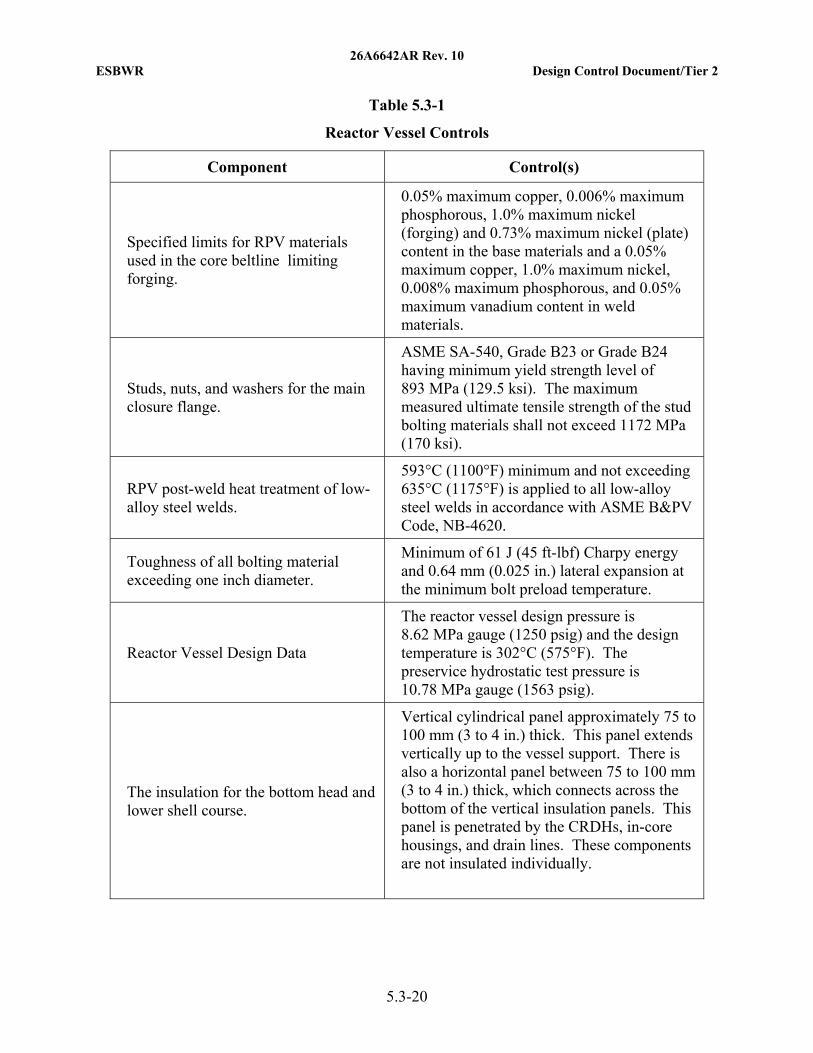
26A6642AR Rev. 10 ESBWR Design Control Document/Tier 2
5.3-20
Table 5.3-1
Reactor Vessel Controls
Component Control(s)
Specified limits for RPV materials used in the core beltline limiting forging.
0.05% maximum copper, 0.006% maximum phosphorous, 1.0% maximum nickel (forging) and 0.73% maximum nickel (plate) content in the base materials and a 0.05% maximum copper, 1.0% maximum nickel, 0.008% maximum phosphorous, and 0.05% maximum vanadium content in weld materials.
Studs, nuts, and washers for the main closure flange.
ASME SA-540, Grade B23 or Grade B24 having minimum yield strength level of 893 MPa (129.5 ksi). The maximum measured ultimate tensile strength of the stud bolting materials shall not exceed 1172 MPa (170 ksi).
RPV post-weld heat treatment of low-alloy steel welds.
593°C (1100°F) minimum and not exceeding 635°C (1175°F) is applied to all low-alloy steel welds in accordance with ASME B&PV Code, NB-4620.
Toughness of all bolting material exceeding one inch diameter.
Minimum of 61 J (45 ft-lbf) Charpy energy and 0.64 mm (0.025 in.) lateral expansion at the minimum bolt preload temperature.
Reactor Vessel Design Data
The reactor vessel design pressure is 8.62 MPa gauge (1250 psig) and the design temperature is 302°C (575°F). The preservice hydrostatic test pressure is 10.78 MPa gauge (1563 psig).
The insulation for the bottom head and lower shell course.
Vertical cylindrical panel approximately 75 to 100 mm (3 to 4 in.) thick. This panel extends vertically up to the vessel support. There is also a horizontal panel between 75 to 100 mm (3 to 4 in.) thick, which connects across the bottom of the vertical insulation panels. This panel is penetrated by the CRDHs, in-core housings, and drain lines. These components are not insulated individually.
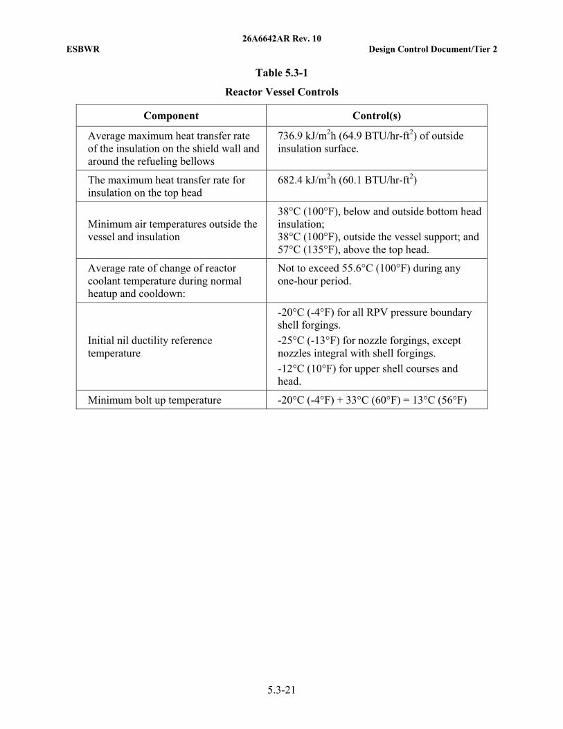
26A6642AR Rev. 10 ESBWR Design Control Document/Tier 2
5.3-21
Table 5.3-1
Reactor Vessel Controls
Component Control(s)
Average maximum heat transfer rate of the insulation on the shield wall and around the refueling bellows
736.9 kJ/m2h (64.9 BTU/hr-ft2) of outside insulation surface.
The maximum heat transfer rate for insulation on the top head
682.4 kJ/m2h (60.1 BTU/hr-ft2)
Minimum air temperatures outside the vessel and insulation
38°C (100°F), below and outside bottom head insulation; 38°C (100°F), outside the vessel support; and57°C (135°F), above the top head.
Average rate of change of reactor coolant temperature during normal heatup and cooldown:
Not to exceed 55.6°C (100°F) during any one-hour period.
Initial nil ductility reference temperature
-20°C (-4°F) for all RPV pressure boundary shell forgings.
-25°C (-13°F) for nozzle forgings, except nozzles integral with shell forgings.
-12°C (10°F) for upper shell courses and head.
Minimum bolt up temperature -20°C (-4°F) + 33°C (60°F) = 13°C (56°F)
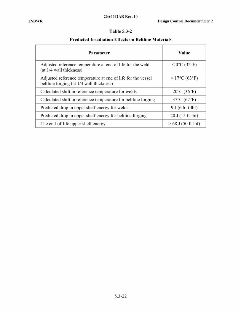
26A6642AR Rev. 10 ESBWR Design Control Document/Tier 2
5.3-22
Table 5.3-2
Predicted Irradiation Effects on Beltline Materials
Parameter Value
Adjusted reference temperature at end of life for the weld (at 1/4 wall thickness)
< 0°C (32°F)
Adjusted reference temperature at end of life for the vessel beltline forging (at 1/4 wall thickness)
< 17°C (63°F)
Calculated shift in reference temperature for welds 20°C (36°F)
Calculated shift in reference temperature for beltline forging 37°C (67°F)
Predicted drop in upper shelf energy for welds 9 J (6.6 ft-lbf)
Predicted drop in upper shelf energy for beltline forging 20 J (15 ft-lbf)
The end-of-life upper shelf energy > 68 J (50 ft-lbf)
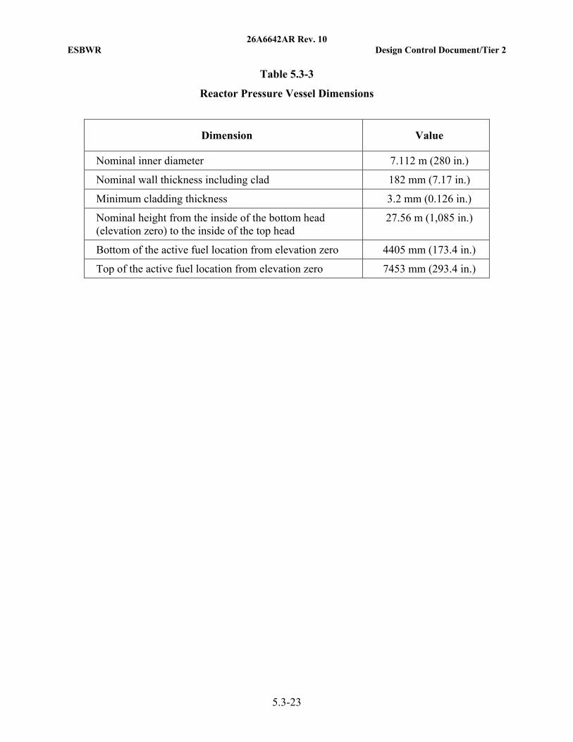
26A6642AR Rev. 10 ESBWR Design Control Document/Tier 2
5.3-23
Table 5.3-3
Reactor Pressure Vessel Dimensions
Dimension Value
Nominal inner diameter 7.112 m (280 in.)
Nominal wall thickness including clad 182 mm (7.17 in.)
Minimum cladding thickness 3.2 mm (0.126 in.)
Nominal height from the inside of the bottom head (elevation zero) to the inside of the top head
27.56 m (1,085 in.)
Bottom of the active fuel location from elevation zero 4405 mm (173.4 in.)
Top of the active fuel location from elevation zero 7453 mm (293.4 in.)
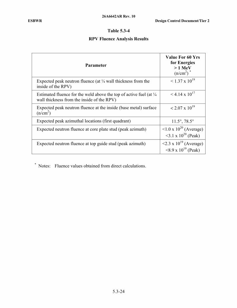
26A6642AR Rev. 10 ESBWR Design Control Document/Tier 2
5.3-24
Table 5.3-4
RPV Fluence Analysis Results
Parameter
Value For 60 Yrs for Energies
> 1 MeV (n/cm2) *
Expected peak neutron fluence (at ¼ wall thickness from the inside of the RPV)
< 1.37 x 10¹⁹
Estimated fluence for the weld above the top of active fuel (at ¼ wall thickness from the inside of the RPV)
< 4.14 x 10¹⁷
Expected peak neutron fluence at the inside (base metal) surface (n/cm2)
< 2.07 x 10¹⁹
Expected peak azimuthal locations (first quadrant) 11.5°, 78.5°
Expected neutron fluence at core plate stud (peak azimuth) <1.0 x 10²⁰ (Average)
<3.1 x 10²⁰ (Peak)
Expected neutron fluence at top guide stud (peak azimuth) <2.3 x 10¹⁹ (Average)
<8.9 x 10¹⁹ (Peak)
* Notes: Fluence values obtained from direct calculations.
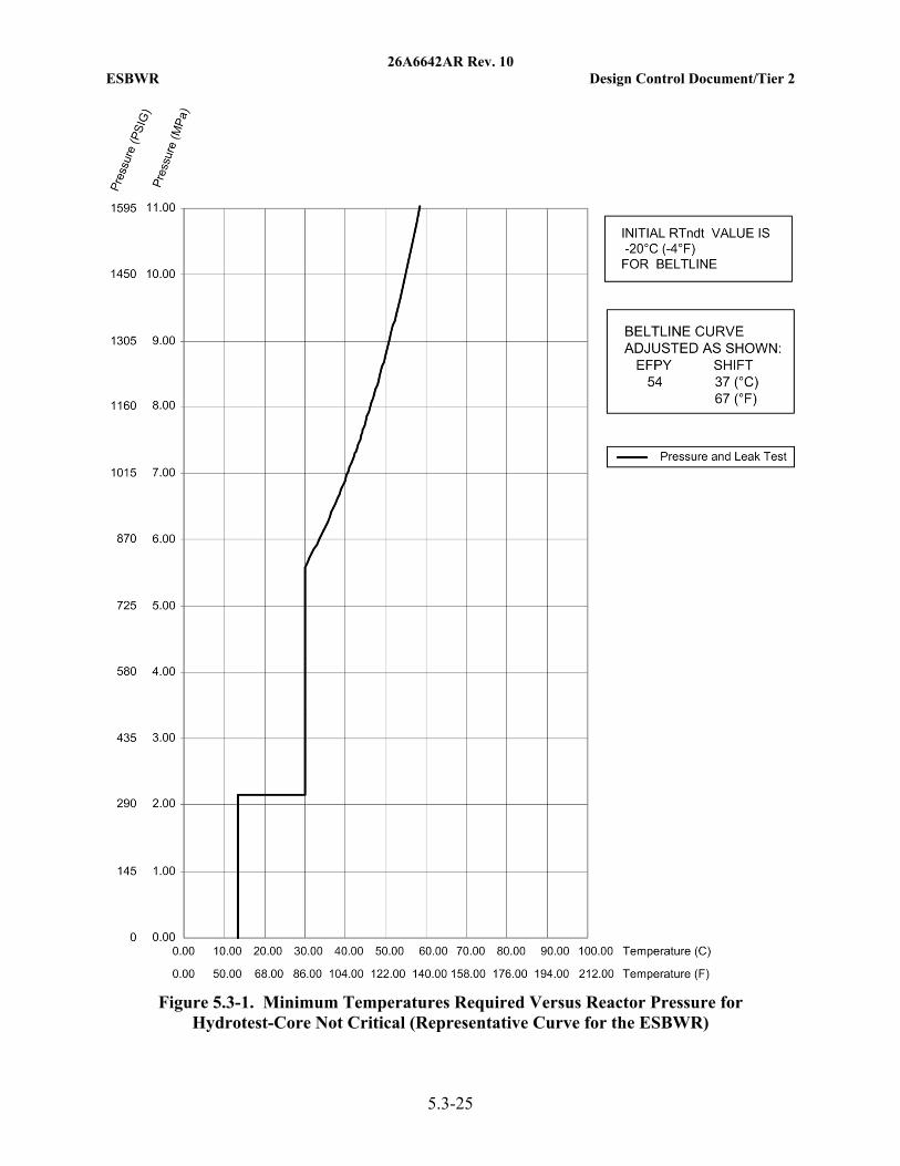
26A6642AR Rev. 10 ESBWR Design Control Document/Tier 2
5.3-25
Figure 5.3-1. Minimum Temperatures Required Versus Reactor Pressure for Hydrotest-Core Not Critical (Representative Curve for the ESBWR)
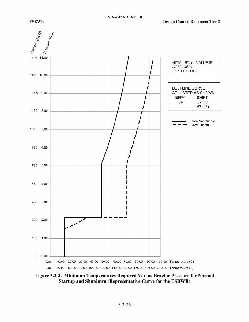
26A6642AR Rev. 10 ESBWR Design Control Document/Tier 2
5.3-26
Figure 5.3-2. Minimum Temperatures Required Versus Reactor Pressure for Normal
Startup and Shutdown (Representative Curve for the ESBWR)
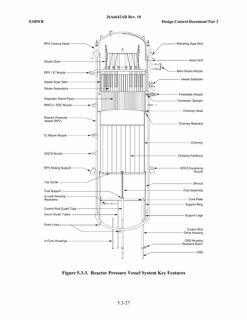
26A6642AR Rev. 10 ESBWR Design Control Document/Tier 2
5.3-27
Figure 5.3-3. Reactor Pressure Vessel System Key Features
26A6642AR Rev. 10 ESBWR Design Control Document/Tier 2
5.4-1
5.4 COMPONENT AND SUBSYSTEM DESIGN
5.4.1 Reactor Recirculation System
The ESBWR relies on buoyancy forces within the reactor vessel to cause recirculation of reactor coolant through the core. There is no forced recirculation system for the ESBWR. The thermal and hydraulic performance of natural recirculation within the reactor core is discussed in Section 4.4.
5.4.1.1 Pump Flywheel Integrity (PWR)
Not applicable to the ESBWR.
5.4.2 Steam Generators (PWR)
5.4.2.1 Steam Generator Materials
Not applicable to the ESBWR.
5.4.2.2 Steam Generator Tube In-service Inspection
Not applicable to the ESBWR.
5.4.3 Reactor Coolant Piping
Because the ESBWR relies on natural circulation within the reactor pressure vessel (RPV), no major external reactor coolant piping is connected to the ESBWR pressure vessel.
5.4.4 Main Steamline Flow Restrictors
5.4.4.1 Safety Design Bases
The main steamline flow restrictors are designed to:
• Limit the loss of coolant from the reactor vessel following a steamline rupture outside the containment;
• Withstand the maximum pressure difference expected across the restrictor following complete severance of a main steamline;
• Limit the amount of radiological release outside of the drywell prior to main steam isolation valve (MSIV) closure; and
• Provide trip signals for MSIV closure.
5.4.4.2 Description
A main steamline flow restrictor (Figure 5.4-1) is provided for each of the four main steamlines with the inside bore of each RPV steam outlet nozzle having the shape of a flow restricting venturi.
The main steamline flow restrictor limits the coolant blowdown rate from the reactor vessel in the event a main steamline break occurs outside the containment (see Table 5.4-1). The flow
26A6642AR Rev. 10 ESBWR Design Control Document/Tier 2
5.4-2
restrictor is designed and fabricated in accordance with the ASME B&PV Code and designed in accordance with the ASME Fluid Meters handbook.
The flow restrictor has no moving parts. Its mechanical structure can withstand the velocities and forces associated with a main steamline break. The flow restrictor design limits flow during a main steamline break to twice the normal full power flow.
The main steamline flow restrictor design substantially limits the steam flow in a severed line, yet it results in negligible increase in steam moisture content during normal operation. The restrictor is also used to measure steam flow to initiate closure of the MSIVs when the steam flow exceeds preselected operational limits. The vessel dome pressure and the venturi throat pressure are used as the high and low pressure sensing locations.
5.4.4.3 Safety Evaluation
In the event that a main steamline breaks outside the containment, the critical flow phenomenon restricts the steam flow rate in the venturi throat (see Table 5.4-1). Prior to isolation valve closure, the total coolant losses from the vessel are not sufficient to produce excessive offsite radiation dose release.
Analysis of the steamline rupture accident (Section 15.4) shows that the core remains covered with water and that the amount of radioactive materials released to the environs through the main steamline break does not exceed the guideline values of published regulations.
The main steamline flow restrictor is Type 308 weld overlay clad. This is similar to the Type 304 cast stainless steel used in previous flow restrictors. It has excellent resistance to erosion/corrosion in a high velocity steam atmosphere. The excellent performance of stainless steel in high velocity steam appears to be due to its resistance to corrosion. A protective surface film forms on the stainless steel, which prevents any surface attack and the steam does not remove this film.
Hardness has no significant effect on erosion/corrosion. For example, hardened carbon steel or alloy steel erodes in applications where soft stainless steel is unaffected.
Surface finish has a minor effect on erosion/corrosion. If very rough surfaces are exposed, the protruding ridges or points erode more rapidly than a smooth surface. Experience shows that if a machined or a ground surface is sufficiently smooth then, no detrimental erosion occurs.
5.4.4.4 Inspection and Testing
Because the flow restrictor forms a permanent part of the RPV steam outlet nozzle and has no moving components, no testing program beyond the RPV in-service inspection is planned.
5.4.4.5 Instrumentation Requirements
None.
26A6642AR Rev. 10 ESBWR Design Control Document/Tier 2
5.4-3
5.4.5 Nuclear Boiler System Isolation
5.4.5.1 Design Bases
Safety Design Bases
The Main Steamline Isolation System is designed to:
• Isolate the main steamlines within the time established by design basis accident (DBA) analyses and under the worst-case pressure and flow conditions postulated in the analyses;
• Isolate the main steamlines in a controlled manner so that simultaneous closure of all steamlines does not induce transients that exceed the nuclear system design limits;
• Isolate each main steamline despite a single failure in either a MSIV or in its associated controls;
• Use local energy to close the MSIVs without relying on electrical power as the motive force;
• Isolate the steamlines at up to reactor design pressure;
• Isolate the main steamlines either during or after seismic, hydrodynamic or safety-relief valve (SRV) or safety valve (SV) blowdown loadings;
• Provide a restriction to reverse steam flow through the broken steamline for the design analysis main steamline break inside containment event until MSIVs have closed;
• Be exercisable during normal operating conditions; and
• Isolate the main steamlines for 100 days following a DBA.
The Feedwater Lines Isolation System is designed to:
• Isolate the feedwater lines within the time established by DBA analyses;
• Isolate the feedwater lines at design maximum BOP feedwater system pressure or at up to reactor design pressure, as required for any analyzed feedwater line break accident;
• Isolate the feedwater lines in a controlled manner so that simultaneous closure of all feedwater lines does not induce transients that exceed the nuclear system design limits;
• Isolate each feedwater line despite a single failure in either a feedwater check valve (FWCV) or feedwater isolation valve (FWIV), or any associated controls;
• Use local energy to close the FWCVs and FWIVs without relying on electrical power as the motive force;
• Isolate the RPV to prevent loss of pressure control for a design basis overfill (level increase) event;
• Isolate the feedwater lines either during or after seismic or hydrodynamic loadings;
• Be exercisable during low-power operating conditions; and
• Isolate the feedwater lines for 100 days following a DBA.
26A6642AR Rev. 10 ESBWR Design Control Document/Tier 2
5.4-4
Power Generation Design Bases
The main steamlines and feedwater lines isolation systems are designed to:
• Open the MSIVs or FWIVs against a specified maximum system differential pressure;
• Allow rated steam flow and feedwater flow to be achieved without exceeding the specified design pressure drop; and
• Be designed so an MSIV or FWIV remains open if one of two solenoid-operated pilot valves fails.
5.4.5.2 Main Steamlines Isolation
5.4.5.2.1 System Description
The main steamlines isolation system is a fail-safe system, that isolates the main steamlines during normal, upset, and accident conditions under the full range of reactor pressures and flow conditions. The system consists of eight MSIV assemblies mounted in four tandem pairs in the main steamlines with one valve of each pair installed inboard of the containment penetration and one valve of each pair installed outboard of the containment penetration. The MSIVs provide isolation of the main steamlines for high-energy line breaks, for containment isolation, and when required during plant shutdown condition. The MSIVs are designed to pass rated steam flow within a design pressure drop, and to limit steamline LOCA inflow to protect containment until the valves are closed. A detailed description of the system is provided below. The detailed description includes all of the functional details required to satisfy the isolation design objectives. The system is shown schematically as part of the Nuclear Boiler System (NBS) in Figure 5.1-2.
5.4.5.2.2 Detailed Main Steam Isolation Valves Description
MSIV characteristics are presented in Table 5.4-1.
The MSIVs are designed to a pressure and temperature consistent with the RPV maximum design conditions. MSIVs are installed welded-in to the main steamlines to maximize the reactor coolant pressure boundary (RCPB) and containment penetration integrity. Each MSIV is designed to accommodate saturated steam at plant operating conditions. The MSIVs assemblies and associated supports are designed to Seismic Category I requirements. The MSIVs form part of the RCPB and are therefore Quality Group A, and designed and fabricated to ASME B&PV Code Section III, Class 1 requirements. The safety-related portions of interconnecting piping are Quality Group C and designed to ASME B&PV Code Section III, Class 3 requirements.
The MSIVs are designed for a minimum life at the specified operating conditions. In addition to minimum wall thickness required for the design pressure, a corrosion allowance is added for the minimum design life (see Table 5.4-1).
MSIV type is a gate pattern with reducing venturi inlet and outlet nozzles to fit the steamline diameter to the valve. The design shall use removable internals for all wear parts and surfaces to permit ease of replacement, or allow refurbishment maintenance outside the valve body. The actuator shall be a high-pressure piston cylinder type. The valve actuator shall be capable of developing sufficient force for opening or closing the valve against a differential up to reactor
26A6642AR Rev. 10 ESBWR Design Control Document/Tier 2
5.4-5
design pressure, and to close against worst-case break flow. Operating power shall come from process-medium integral actuation (preferred design) or high-pressure nitrogen (or nitrogen-spring) yoke-mounted actuation (alternate design).
The MSIVs are designed to close under peak accident environmental radiation, pressure, and temperature conditions. In addition, they are designed to remain closed under long-term post-accident environmental conditions (see Table 5.4-1). The MSIVs must provide bi-directional flow isolation to prevent steam discharge to the external environment, and to limit steam blow-back into containment through a ruptured main steamline in the event of a LOCA. Pressure drop is adjusted by the sizing of valve flow orifice diameter of the inboard and outboard MSIVs to meet design requirements. The closed MSIV leak rate is sufficiently low to provide a margin for wear and degradation during operating service so that total leakage remains within the design allowable for the cumulative leak rate through all four main steamlines. The bidirectional isolation capability and valve orifice sizing prevents excess steam mass and energy from entering the containment during the initial containment pressurization of a LOCA. Each MSIV is nominally designed for minimal flow disruption in the full-open position to limit acoustic loads in the steam portion of the NBS. Stem travel is sufficient to clear the flow stream and prevent stem assembly flow interaction when the valve is full-open minimizing deleterious effects caused by flow-induced vibration.
Valve closure occurs when both of two automatic control pilot solenoid-operated valves are deenergized. Speed shall be controlled by cylinder inlet and exhaust path orifice sizing and factory set to provide the design stroke speed under rated operating and accident flow conditions. The MSIV actuates at two closing speeds (see Table 5.4-1), including a fast isolation closure by the automatic pilots, and a slow-closure speed for exercise. A separate solenoid-operated pilot valve, manually operated from the control room, is provided for a slow-closure partial- or full-stroke exercise cycle testing.
The MSIVs are supplied pneumatic service, as required, for maintenance testing and open-stroke exercising.
5.4.5.2.3 Main Steam Isolation Operation
The MSIVs are remote-manually operated from the main control room. Each valve is individually controllable. During normal plant operation, the MSIVs can be tested by cycling them in the slow closing speed (this may require a reduction of reactor power to maintain steam flow and pressure within limits). Once initiated, the test sequence is automatic. After normal plant shutdown, the valves can be closed with remote manual switches.
The MSIVs close at fast speed on various automatic signals indicating abnormal plant conditions, including:
• Reactor low water level;
• Main steamline high flow;
• Low turbine inlet pressure;
• Main steamline tunnel (outside containment) high ambient temperature;
• Low condenser vacuum (unless procedurally bypassed); and
26A6642AR Rev. 10 ESBWR Design Control Document/Tier 2
5.4-6
• Turbine building high main steamline ambient temperature.
In the most demanding case (a main steamline rupture downstream of an outboard MSIV), steam flow quickly increases until a venturi flow restrictor installed in each reactor vessel steam nozzle prevents further increase. During the initial part of valve closure travel the MSIV stem movement causes little effect on flow reduction because the RPV venturi restrictor chokes the flow. When the valve is sufficiently closed, the flow area approximately matches the venturi restrictor and, thereafter, steam flow is reduced as a function of the valve area versus travel characteristic.
5.4.5.3 Feedwater Lines Isolation
5.4.5.3.1 Feedwater Isolation Description
The feedwater lines isolation system is a fail-safe system that isolates the feedwater lines during normal, upset, and accident conditions under the full range of reactor and feedwater system pressures and flows. The system consists of four FWIVs, four FWCVs, and two branch connection isolation valves, as shown schematically as part of the NBS in Figure 5.1-2. One FWCV is installed as the inboard containment isolation valve and each of two in-series FWIVs are installed as outboard containment isolation valves in each feedwater line. The branch connection on each feedwater line is installed between the penetration outboard end and the first FWIV, and is isolated by a testable check valve. This arrangement satisfies the requirements of General Design Criteria (GDC) 55. The second FWIV and FWCV provide functional redundancy to meet the safety-related isolation design function requirements.
5.4.5.3.2 Detailed Feedwater Isolation Valves Description
FWIV, FWCV and the branch isolation valve characteristics are presented in Table 5.4-1. The FWCVs provide the primary isolation in the event of a HELB in the feedwater piping outboard of the NBS system. The testable check valves, along with the inboard containment isolation FWCVs, provide isolation in the event of a high energy line break (HELB) in the branch connected piping systems. The FWIVs provide primary isolation in the event of a feedwater line LOCA, and for a vessel overfill (reactor level high) event.
The feedwater isolation system is designed to a pressure and temperature commensurate with the maximum feedwater system conditions, which bound the RPV maximum design conditions. The feedwater isolation system and associated supports are design to meet Seismic Category I requirements. The inboard containment isolation FWCVs, the two outboard containment isolation FWIVs and the containment isolation branch testable check valves are part of the RCPB and are designated Quality Group A, and are designed and fabricated to ASME B&PV Code Section III, Class 1 requirements. The remainder of the feedwater isolation system is designated Quality Group B, and the valves are designed and fabricated to ASME B&PV Code Section III, Class 2 requirements.
The feedwater isolation system components are designed for a minimum life at the specified operating conditions. In addition to minimum wall thickness required for the design pressure, a corrosion allowance is added for the minimum design life (see Table 5.4-1).
FWIV type is a gate pattern with reducing venturi inlet and outlet nozzles to fit the steam line diameter to the valve. The design uses removable internals for all wear parts and surfaces to
26A6642AR Rev. 10 ESBWR Design Control Document/Tier 2
5.4-7
permit ease of replacement, or allow refurbishment maintenance outside the valve body. The actuator is a high-pressure piston cylinder type. The valve actuator is capable of developing sufficient force for closing the valve at the design pressure differential indicated on Table 5.4-1, and for opening the valve as required to support feedwater injection for reactor makeup. Operating power comes from process-medium integral actuation (preferred design) or high-pressure nitrogen (or nitrogen-spring) yoke-mounted actuation (alternate design). Valve closure occurs when both of two automatic control pilot solenoid-operated valves are energized. Speed is controlled by cylinder inlet and exhaust path orifice sizing and factory set to provide the design stroke speed under rated operating and accident flow conditions.
The FWIVs, FWCVs and branch piping testable check valves are designed to close under peak accident environmental radiation, pressure, and temperature conditions. The portion of the feedwater system that forms the feedwater penetration zone is designed to a pressure that is above that of the BOP feedwater system design pressure to provide protection for the rest of the RCPB from malfunctions of the FWCS. When required to isolate the feedwater lines, the FWIV closures is assured by designing them for operation at a pressure well above the design pressure of the BOP feedwater system. In addition, they are designed to remain closed under long-term post-accident environmental conditions (see Table 5.4-1). The FWIVs and FWCVs are designed to tolerate the loads resulting from the most rapid closure condition, and to mitigate to the extent practical the hydraulic affects of rapid closure.
The branch isolation valves are testable checks and also designed to tolerate loads resulting from the most rapid valve closure condition. The disk has a design-augmented load to assist leak-tight seating. The augmented load is low enough to allow condensate makeup systems to push open the disk for post-event injection into the RPV without restoration of any actuation or control power to the valves.
The FWIVs, and feedwater lines branch connection testable check isolation valves, are supplied pneumatic service, as required, for maintenance testing and open-stroke exercising.
5.4.5.3.3 Feedwater Isolation System Operation
The FWIVs are remote-manually operated from the main control room. Each valve is individually controllable. During low-power plant operation, the FWIVs can be exercised by cycling them one feedwater line at a time. After normal plant shutdown, the valves can be maintained closed or open with remote manual switches.
The FWIVs close on various automatic signals indicating abnormal plant conditions, including:
• Feedwater lines differential pressure with coincident drywell high pressure;
• Drywell high pressure with coincident lower drywell high water level;
• Drywell high-high pressure;
• Reactor low-low water level with a time delay; and
• Reactor high water level.
The FWCVs close on feedwater flow deceleration and reversal indicating abnormal feedwater system conditions upstream of the NBS interface. Similarly, the branch line testable check valves will close on flow deceleration and reversal indicating abnormal conditions upstream of
26A6642AR Rev. 10 ESBWR Design Control Document/Tier 2
5.4-8
the NBS branch connection interface. The testable check valves also close if feedwater system pressure exceeds the system pressure upstream of the NBS interface in order to protect the upstream piping system.
5.4.5.3.4 Feedwater Pump ASD Controller Circuit Breakers
During the events that require feedwater isolation, especially events when the FWCS demands maximum flow from the feedwater pumps due to valid or invalid low reactor level signals, a backup trip signal is generated by the LD&IS. The LD&IS will interrupt controller power from the FWCS to the feedwater pump adjustable speed drives (ASD) by opening safety-related ASD controller circuit breakers. Removing power from the ASD controllers causes the ASDs to reduce feedwater pump motor speed to 0 rpm.
The safety-related ASD controller circuit breakers are located in the Control Building.
5.4.5.4 Safety Evaluation
The main steamline isolation system is designed to accomplish the following safety-related functions:
• Limit the loss of reactor coolant in the event of a main steamline break;
• Limit the release of normal reactor coolant radioactivity to the environment in the event of a main steamline break;
• Limit the flow of steam back into containment through a broken main steamline; and
• Help maintain long-term containment leaktightness for accidents in which a significant radioactive release from the reactor core is postulated.
The analysis of a complete, sudden steamline break outside the containment is described in Subsection 15.4.5. The analysis shows that the fuel barrier is protected against loss of cooling if the MSIVs close within the longest design closing time (see Table 5.4-1) plus instrumentation (closing signal) delay. The calculated radiological effects of the radioactive material assumed to be released with the steam are within the guideline values.
The analyses of other loss-of-coolant-accidents in which large radioactive source terms are postulated are also discussed in Subsection 15.4.5. These analyses demonstrate that acceptable off-site dose consequences are maintained when containment leaktightness is maintained, including the specified MSIV leaktightness, and assuming failure of one MSIV to close.
The shortest design closing time of the MSIVs (see Table 5.4-1) is also shown to be satisfactory. In the limiting transient [MSIV closure with failure of direct scram (i.e., scram occurs on high neutron flux rather than MSIV position)] reactor vessel design limits are not exceeded (Subsection 15.5.1).
The ability of the MSIV to close in a few seconds after a steamline break, under conditions of high pressure differentials and flow rates and with flow mixtures ranging from mostly steam to mostly water is demonstrated by dynamic testing.
26A6642AR Rev. 10 ESBWR Design Control Document/Tier 2
5.4-9
The feedwater line isolation system is designed to accomplish the following safety-related functions:
• Limit the overfill of the RPV due to a postulated feed-level increase event to protect RPV pressure control and core decay heat removal capability through the main steamlines;
• Limit the loss of reactor coolant in the event of a feedwater line HELB;
• Limit the release of normal reactor coolant radioactivity to the environment in the event of feedwater line break;
• Limit the flow of condensate into containment through a broken feedwater line; and
• Help maintain long-term containment leaktightness for accidents in which a significant radioactive release from the reactor core is postulated.
The analyses of LOCAs in which large radioactive source terms are postulated are discussed in Section 15.4. These analyses demonstrate that acceptable off-site dose consequences are maintained when containment leaktightness is maintained, including the specified feedwater isolation system leaktightness, and assuming failure of one isolation valve to close.
The shortest design closing time of the FWIVs is satisfactory to assure completion of the function without inducing damage by too rapid hydraulic isolation. The ability of an FWIV to close in a few seconds after a feedwater line break, under conditions of maximum feedwater system pressure differential and flow rate, is demonstrated by dynamic testing. The closure time ensures that the results of the accident analysis (Section 6.3) for the postulated mass and energy inflow from a broken feedwater line into the containment is bounding. This same stroke time is sufficient to limit the level increase in the RPV due to a postulated overfill event so that vessel integrity and core cooling are adequately protected.
The rapid check-closed isolation characteristic of the FWCVs and branch isolation testable check valves limits the discharge of pressurized reactor coolant out of the containment. The closure characteristic of these valves minimizes, to the extent practical, the hydraulic loads that may be induced by rapid valve closure to levels less than the design loads of the piping systems.
Two isolation valves provide redundancy so either can perform the isolation function. This also permits leak-testing either valve during shutdown after the other valve is closed. The inside valve, outside valve, and respective control systems are physically separated.
Electrical equipment associated with the isolation valves and operated in an accident environment are limited to the wiring, solenoid valves, junction boxes, electrical connectors, and position switches on the isolation valves.
5.4.5.5 Testing and Inspection Requirements
During fabrication, the following tests (among others) are performed to assure that the MSIVs and FWIVs function as designed:
• Verification of MSIV and FWIV closing speeds (see Table 5.4-1) - each valve is tested at rated pressure;
• Seat leakage measurements - both water leakage and air leakage; and
26A6642AR Rev. 10 ESBWR Design Control Document/Tier 2
5.4-10
• Hydrostatic testing and nondestructive examinations per ASME B&PV Code requirements.
After installation, preoperational testing (described in Section 14.2) assures that the MSIVs and FWIVs will operate as designed, including opening and closing strokes, leaktightness, generation of position indication signals, and response to automatic actuation logic signals.
The MSIVs are tested for operability during plant operation by periodic test cycling. The MSIVs and FWIVs are tested for operability during planned outages. During outages, the MSIVs, FWIVs, FWCVs, and branch isolation testable check valves are functionally tested, leak-tested, and visually inspected as required by their corresponding programs. Leak-testing provisions are further discussed in Subsection 6.2.6. Required periodic tests and inspections of the MSIVs and FWIVs are identified in the plant-specific Technical Specifications.
5.4.5.6 Instrumentation Requirements
MSIV and FWIV positions are indicated in the main control room. The safety-related position sensors provide multiple independent channels to support safety-related instrument and control signal requirements.
Additional position indication sensing (e.g., limit switches, or other means) is provided on each valve, as required to support nonsafety-related instrumentation and control requirements. Additional position indication is used on the MSIVs for initiating a turbine control system trip and for signal input to the DPS logic. The FWIVs are also provided additional position indication for signal input to the DPS logic.
MSIV and FWIV instrumentation requirements are described further in Section 7.3.3.
5.4.6 Isolation Condenser System
The ESBWR ICS is the most comparable system to the BWR Reactor Core Isolation Cooling (RCIC) System. The ESBWR is a passive plant relying almost exclusively on natural phenomena to drive plant functions, which differs significantly from the BWR RCIC which relies heavily on active systems to accomplish its functions. However, the ESBWR ICS does meet acceptance criteria that are based on meeting the relevant requirements of GDC 4, 5, 33, 34, 54, 55, and 10 CFR 50.63. The specific criteria met by the ESBWR to meet the requirements of the above GDCs and 10 CFR 50.63 are as follows:
• GDC 4, as related to dynamic effects associated with flow instabilities and loads (e.g. water hammer);
• GDC 5 as it relates to safety-related structures, systems and components not being shared among nuclear power units unless it can be demonstrated that sharing does not impair its ability to perform its safety function;
• GDC 33 as it relates to the system capability to provide reactor coolant makeup for protection against small breaks in the RCPB so the fuel design limits are not exceeded;
• GDC 34 as it relates to the system design being capable of removing fission product decay heat and other residual heat from the reactor core to preclude fuel damage or RCPB overpressurization;
26A6642AR Rev. 10 ESBWR Design Control Document/Tier 2
5.4-11
• GDC 54 as it relates to piping systems penetrating primary containment being provided with leak detection and isolation capabilities.
• GDC 55 as it relates to isolation for piping systems that are part of RCPB and penetrate containment; and
• 10 CFR 50, §50.63, “Loss of All Alternating Current (AC) Power,” as related to design provisions to support the plant's ability to withstand and recover from a Station Black-Out of a specified duration.
The ESBWR passive decay heat removal systems (Isolation Condensers) are capable of achieving and maintaining safe stable conditions for at least 72 hours without operator action following non-LOCA events. Operator action is credited after 72 hours to refill Isolation Condenser pools or initiate non-safety shutdown cooling.
5.4.6.1 Design Bases
5.4.6.1.1 Safety Design Bases
Functions
The ICS removes residual sensible and core decay heat from the reactor, in a passive way and with minimal loss of coolant inventory from the reactor, when the normal heat removal system is unavailable, following any of the following events:
• Station blackout (i.e., unavailability of all AC power);
• Anticipated transient without scram (See Subsection 15.5.4.3); and
• Loss-of-coolant-accident.
The ICS functions to avoid unnecessary use of other engineered safety features (ESFs) for residual heat removal (RHR). In the event of a LOCA, the ICS also provides additional liquid inventory upon opening of the condensate return valves to initiate the system. In the event of ICS initiation by reactor level below Level 2, the ICS also removes core heat causing initial depressurization of the reactor before the ADS initiates. Because of this vessel pressure reduction with return of condensed steam plus the additional initial ICS stored condensate inventory, the ADS can initiate from a lower reactor water level to complete the vessel depressurization.
The ICS is designed as a safety-related system to remove reactor decay heat following reactor shutdown and isolation. It also prevents unnecessary reactor depressurization, and operation of other ESFs, that can also perform this function.
In the event of a LOCA, the ICS provides additional liquid inventory upon opening of the condensate return valves to initiate the system. Upon the opening of any two DPVs, the ICS isolation valves are automatically signaled to close. Closing the ICS isolation valves when the RPV is depressurized mitigates the accumulation of radiolytic hydrogen and oxygen (see Reference 5.4-3). The ICS also provides initial depressurization of the reactor before ADS in event of loss of feed water, such that the ADS can take place from a lower water level.
In order to ensure an adequate inventory of cooling water is available for at least 72 hours following an accident, each IC/PCCS pool is connected to the equipment storage pool by two
26A6642AR Rev. 10 ESBWR Design Control Document/Tier 2
5.4-12
valves in parallel where one valve is a pneumatic-operated valve with an accumulator and the other is a squib valve. These valves, which are shown in the valve rooms depicted on Figure 6.2-2, open on a low level condition in either of the IC/PCCS inner expansion pools and allow the water volume in the equipment storage pool and reactor well to communicate with the IC/PCCS pools.
General System Requirements
The ICS is designed to remove post-reactor isolation decay heat with 3 out of 4 isolation condenser heat exchangers operating and to reduce Nuclear Steam Supply System (NSSS) temperature to safe shutdown conditions in 36 hours (and NSSS pressure below containment design conditions in 72 hours) with automatic and continuous venting of radiolytically generated noncondensable gases from the lower header to the suppression pool beginning six hours after isolation (see Table 5.4-1). The isolation condenser heat exchangers are independent of plant AC power, and they function whenever normal heat removal systems are unavailable, to maintain reactor pressure and temperature below limits.
The ICS is designed and qualified as a safety-related system.
The ICS provides isolation valves for containment isolation (Subsection 6.2.4).
Performance Requirements
The heat removal capacity of the ICS (with three of four isolation condenser trains in service) at reactor pressure with saturated steam is presented in Table 5.4-1. The condensate return valve stroke-open time and logic delay time is presented in Table 5.4-1.
5.4.6.1.2 Power Generation Design Bases
The ICS automatically limits the reactor pressure and prevents SRV operation following an AOO.
The ICS removes excess sensible and core decay heat from the reactor, in a passive way and with minimal loss of coolant inventory from the reactor, when the normal heat removal system is unavailable, following AOOs and any event that results in reactor isolation.
5.4.6.2 System Description
5.4.6.2.1 Summary Description
The ICS consists of four independent trains, each containing an isolation condenser that condenses steam on the tube side and transfers heat to the IC/PCCS pool, which is vented to the atmosphere as shown on Figure 5.1-3.
The isolation condenser, connected by piping to the RPV, is placed at an elevation above the source of steam (vessel) and, when the steam is condensed, the condensate is returned to the vessel via a condensate return pipe.
The steam side connection between the vessel and the isolation condenser is normally open and the condensate line is normally closed. This allows the isolation condenser and drain piping to fill with condensate, which is maintained at a subcooled temperature by the pool water during normal reactor operation.
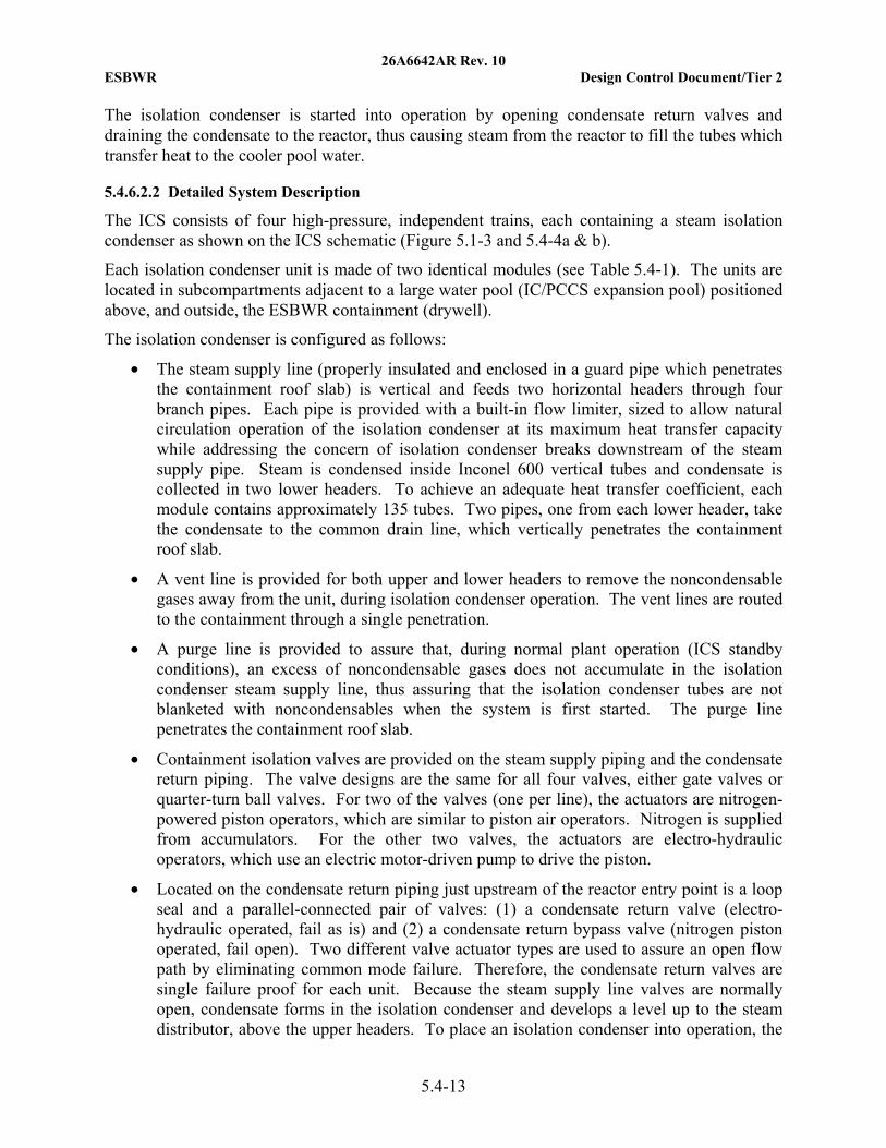
26A6642AR Rev. 10 ESBWR Design Control Document/Tier 2
5.4-13
The isolation condenser is started into operation by opening condensate return valves and draining the condensate to the reactor, thus causing steam from the reactor to fill the tubes which transfer heat to the cooler pool water.
5.4.6.2.2 Detailed System Description
The ICS consists of four high-pressure, independent trains, each containing a steam isolation condenser as shown on the ICS schematic (Figure 5.1-3 and 5.4-4a & b).
Each isolation condenser unit is made of two identical modules (see Table 5.4-1). The units are located in subcompartments adjacent to a large water pool (IC/PCCS expansion pool) positioned above, and outside, the ESBWR containment (drywell).
The isolation condenser is configured as follows:
• The steam supply line (properly insulated and enclosed in a guard pipe which penetrates the containment roof slab) is vertical and feeds two horizontal headers through four branch pipes. Each pipe is provided with a built-in flow limiter, sized to allow natural circulation operation of the isolation condenser at its maximum heat transfer capacity while addressing the concern of isolation condenser breaks downstream of the steam supply pipe. Steam is condensed inside Inconel 600 vertical tubes and condensate is collected in two lower headers. To achieve an adequate heat transfer coefficient, each module contains approximately 135 tubes. Two pipes, one from each lower header, take the condensate to the common drain line, which vertically penetrates the containment roof slab.
• A vent line is provided for both upper and lower headers to remove the noncondensable gases away from the unit, during isolation condenser operation. The vent lines are routed to the containment through a single penetration.
• A purge line is provided to assure that, during normal plant operation (ICS standby conditions), an excess of noncondensable gases does not accumulate in the isolation condenser steam supply line, thus assuring that the isolation condenser tubes are not blanketed with noncondensables when the system is first started. The purge line penetrates the containment roof slab.
• Containment isolation valves are provided on the steam supply piping and the condensate return piping. The valve designs are the same for all four valves, either gate valves or quarter-turn ball valves. For two of the valves (one per line), the actuators are nitrogen-powered piston operators, which are similar to piston air operators. Nitrogen is supplied from accumulators. For the other two valves, the actuators are electro-hydraulic operators, which use an electric motor-driven pump to drive the piston.
• Located on the condensate return piping just upstream of the reactor entry point is a loop seal and a parallel-connected pair of valves: (1) a condensate return valve (electro-hydraulic operated, fail as is) and (2) a condensate return bypass valve (nitrogen piston operated, fail open). Two different valve actuator types are used to assure an open flow path by eliminating common mode failure. Therefore, the condensate return valves are single failure proof for each unit. Because the steam supply line valves are normally open, condensate forms in the isolation condenser and develops a level up to the steam distributor, above the upper headers. To place an isolation condenser into operation, the
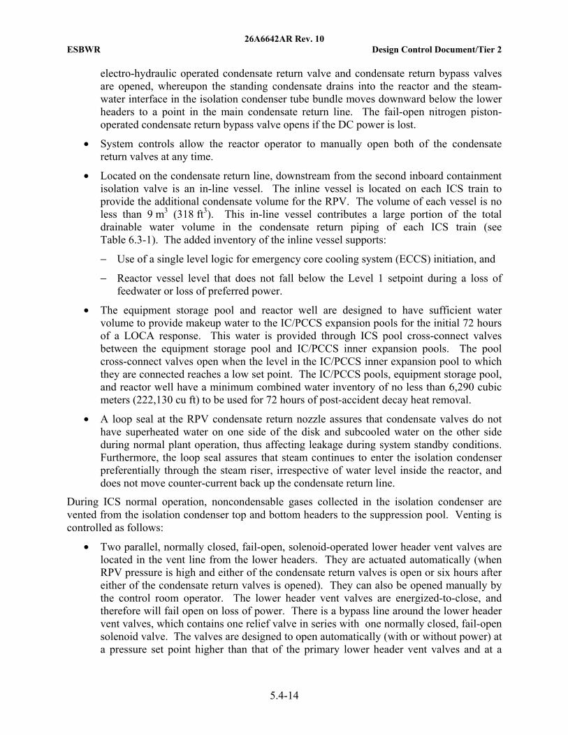
26A6642AR Rev. 10 ESBWR Design Control Document/Tier 2
5.4-14
electro-hydraulic operated condensate return valve and condensate return bypass valves are opened, whereupon the standing condensate drains into the reactor and the steam-water interface in the isolation condenser tube bundle moves downward below the lower headers to a point in the main condensate return line. The fail-open nitrogen piston-operated condensate return bypass valve opens if the DC power is lost.
• System controls allow the reactor operator to manually open both of the condensate return valves at any time.
• Located on the condensate return line, downstream from the second inboard containment isolation valve is an in-line vessel. The inline vessel is located on each ICS train to provide the additional condensate volume for the RPV. The volume of each vessel is no less than 9 m3 (318 ft3). This in-line vessel contributes a large portion of the total drainable water volume in the condensate return piping of each ICS train (see Table 6.3-1). The added inventory of the inline vessel supports:
− Use of a single level logic for emergency core cooling system (ECCS) initiation, and
− Reactor vessel level that does not fall below the Level 1 setpoint during a loss of feedwater or loss of preferred power.
• The equipment storage pool and reactor well are designed to have sufficient water volume to provide makeup water to the IC/PCCS expansion pools for the initial 72 hours of a LOCA response. This water is provided through ICS pool cross-connect valves between the equipment storage pool and IC/PCCS inner expansion pools. The pool cross-connect valves open when the level in the IC/PCCS inner expansion pool to which they are connected reaches a low set point. The IC/PCCS pools, equipment storage pool, and reactor well have a minimum combined water inventory of no less than 6,290 cubic meters (222,130 cu ft) to be used for 72 hours of post-accident decay heat removal.
• A loop seal at the RPV condensate return nozzle assures that condensate valves do not have superheated water on one side of the disk and subcooled water on the other side during normal plant operation, thus affecting leakage during system standby conditions. Furthermore, the loop seal assures that steam continues to enter the isolation condenser preferentially through the steam riser, irrespective of water level inside the reactor, and does not move counter-current back up the condensate return line.
During ICS normal operation, noncondensable gases collected in the isolation condenser are vented from the isolation condenser top and bottom headers to the suppression pool. Venting is controlled as follows:
• Two parallel, normally closed, fail-open, solenoid-operated lower header vent valves are located in the vent line from the lower headers. They are actuated automatically (when RPV pressure is high and either of the condensate return valves is open or six hours after either of the condensate return valves is opened). They can also be opened manually by the control room operator. The lower header vent valves are energized-to-close, and therefore will fail open on loss of power. There is a bypass line around the lower header vent valves, which contains one relief valve in series with one normally closed, fail-open solenoid valve. The valves are designed to open automatically (with or without power) at a pressure set point higher than that of the primary lower header vent valves and at a
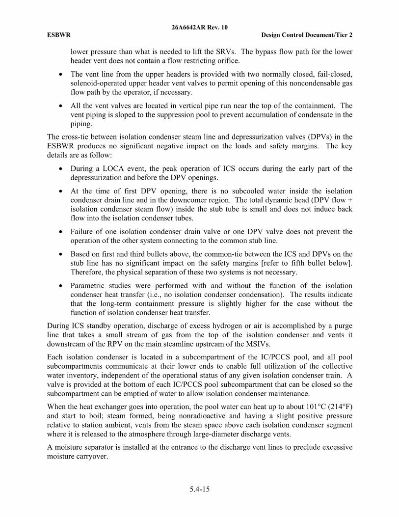
26A6642AR Rev. 10 ESBWR Design Control Document/Tier 2
5.4-15
lower pressure than what is needed to lift the SRVs. The bypass flow path for the lower header vent does not contain a flow restricting orifice.
• The vent line from the upper headers is provided with two normally closed, fail-closed, solenoid-operated upper header vent valves to permit opening of this noncondensable gas flow path by the operator, if necessary.
• All the vent valves are located in vertical pipe run near the top of the containment. The vent piping is sloped to the suppression pool to prevent accumulation of condensate in the piping.
The cross-tie between isolation condenser steam line and depressurization valves (DPVs) in the ESBWR produces no significant negative impact on the loads and safety margins. The key details are as follow:
• During a LOCA event, the peak operation of ICS occurs during the early part of the depressurization and before the DPV openings.
• At the time of first DPV opening, there is no subcooled water inside the isolation condenser drain line and in the downcomer region. The total dynamic head (DPV flow + isolation condenser steam flow) inside the stub tube is small and does not induce back flow into the isolation condenser tubes.
• Failure of one isolation condenser drain valve or one DPV valve does not prevent the operation of the other system connecting to the common stub line.
• Based on first and third bullets above, the common-tie between the ICS and DPVs on the stub line has no significant impact on the safety margins [refer to fifth bullet below]. Therefore, the physical separation of these two systems is not necessary.
• Parametric studies were performed with and without the function of the isolation condenser heat transfer (i.e., no isolation condenser condensation). The results indicate that the long-term containment pressure is slightly higher for the case without the function of isolation condenser heat transfer.
During ICS standby operation, discharge of excess hydrogen or air is accomplished by a purge line that takes a small stream of gas from the top of the isolation condenser and vents it downstream of the RPV on the main steamline upstream of the MSIVs.
Each isolation condenser is located in a subcompartment of the IC/PCCS pool, and all pool subcompartments communicate at their lower ends to enable full utilization of the collective water inventory, independent of the operational status of any given isolation condenser train. A valve is provided at the bottom of each IC/PCCS pool subcompartment that can be closed so the subcompartment can be emptied of water to allow isolation condenser maintenance.
When the heat exchanger goes into operation, the pool water can heat up to about 101°C (214°F) and start to boil; steam formed, being nonradioactive and having a slight positive pressure relative to station ambient, vents from the steam space above each isolation condenser segment where it is released to the atmosphere through large-diameter discharge vents.
A moisture separator is installed at the entrance to the discharge vent lines to preclude excessive moisture carryover.
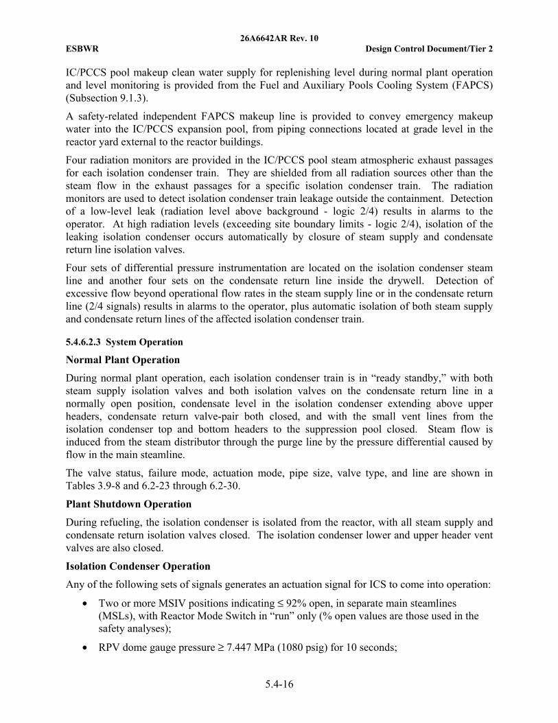
26A6642AR Rev. 10 ESBWR Design Control Document/Tier 2
5.4-16
IC/PCCS pool makeup clean water supply for replenishing level during normal plant operation and level monitoring is provided from the Fuel and Auxiliary Pools Cooling System (FAPCS) (Subsection 9.1.3).
A safety-related independent FAPCS makeup line is provided to convey emergency makeup water into the IC/PCCS expansion pool, from piping connections located at grade level in the reactor yard external to the reactor buildings.
Four radiation monitors are provided in the IC/PCCS pool steam atmospheric exhaust passages for each isolation condenser train. They are shielded from all radiation sources other than the steam flow in the exhaust passages for a specific isolation condenser train. The radiation monitors are used to detect isolation condenser train leakage outside the containment. Detection of a low-level leak (radiation level above background - logic 2/4) results in alarms to the operator. At high radiation levels (exceeding site boundary limits - logic 2/4), isolation of the leaking isolation condenser occurs automatically by closure of steam supply and condensate return line isolation valves.
Four sets of differential pressure instrumentation are located on the isolation condenser steam line and another four sets on the condensate return line inside the drywell. Detection of excessive flow beyond operational flow rates in the steam supply line or in the condensate return line (2/4 signals) results in alarms to the operator, plus automatic isolation of both steam supply and condensate return lines of the affected isolation condenser train.
5.4.6.2.3 System Operation
Normal Plant Operation
During normal plant operation, each isolation condenser train is in “ready standby,” with both steam supply isolation valves and both isolation valves on the condensate return line in a normally open position, condensate level in the isolation condenser extending above upper headers, condensate return valve-pair both closed, and with the small vent lines from the isolation condenser top and bottom headers to the suppression pool closed. Steam flow is induced from the steam distributor through the purge line by the pressure differential caused by flow in the main steamline.
The valve status, failure mode, actuation mode, pipe size, valve type, and line are shown in Tables 3.9-8 and 6.2-23 through 6.2-30.
Plant Shutdown Operation
During refueling, the isolation condenser is isolated from the reactor, with all steam supply and condensate return isolation valves closed. The isolation condenser lower and upper header vent valves are also closed.
Isolation Condenser Operation
Any of the following sets of signals generates an actuation signal for ICS to come into operation:
• Two or more MSIV positions indicating ≤ 92% open, in separate main steamlines (MSLs), with Reactor Mode Switch in “run” only (% open values are those used in the safety analyses);
• RPV dome gauge pressure ≥ 7.447 MPa (1080 psig) for 10 seconds;
26A6642AR Rev. 10 ESBWR Design Control Document/Tier 2
5.4-17
• Reactor water level below Level 2, with time delay;
• Reactor water below Level 1;
• Loss of Feed Water (loss of power to 2-out-of-4 feed water pumps) in Reactor Run Mode; and
• Operator manual initiation.
When one of these ICS initiation signals occurs, condensate return valves open within required stroke time (Table 5.4-1), which starts isolation condenser operation. After a six-hour time delay following initiation, the lower header vent valves (F009 and F0101) automatically open to prevent the accumulation of radiolytically generated hydrogen and oxygen (see Reference 5.4-3). If the pressure increases above 7.929 MPa gauge (1150 psig), the lower header vent bypass valves (F011 and F012) automatically open.
In the early stages of RCS depressurization (0 ~ 500 seconds, before the opening of DPVs), the ICS is in operation and condenses significant steam flow (~ 36 kg/s (79.4 lbm/s) per isolation condenser, MSL break case) from the RPV. The steam flow to the ICS reduces as the RPV pressure decreases and the downcomer water level drops. The first group of ADS valves open after the downcomer level drops below the Level 1 setpoint (Table 6.3-1, Item B.5; NOTE: Level 1 is representatively shown on Figure 7.7-1). Consequently, both the RPV pressure and the steam flow to the ICS reduce further after the first ADS valve opening. The first group of DPV valves opens at 50 seconds after the first ADS valve opening. At this time, the RPV pressure decreases to about 700 kPa (100 psia), the DPV flow is about 7.5 kg/s (16.5 lbm/s) per DPV and the isolation condenser steam flow reduces to about 4 kg/s (8.8 lbm/s) per isolation condenser. The total velocity inside the stub tube is in the range of 35 m/s (114.8 ft/s). The dynamic head is in the range of 2.2 kPa (0.3 psia), which is small compared to the static head of two-phase mixture in the vertical portion of the isolation condenser drain line.
At the time of DPV opening, the RPV downcomer as well as the isolation condenser drain lines are filled with saturated two-phase mixture due to the fast depressurization resulting from the opening of ADS valves. As the result of additional depressurization from the DPV opening, the downcomer two-phase level could swell up a few meters from the Level 1 position, and get closer to or below the stub line elevation. However, there is no subcooled water inside the isolation condenser drain line, or inside the downcomer near by the nozzle elevations of the isolation condenser drain line or the stub line.
In addition, there are loop seals at the lowest elevation of the isolation condenser drain lines, near by the injection nozzles. The loop seal provides extra static head; in addition to the 15 meters (49.2 feet) of static head of the two-phase mixture inside the vertical portion of the isolation condenser drain line, to prevent any flow reversal in the isolation condenser drain line and steam inlet line due to the DPV opening.
The ICS is also designed to provide makeup water to the RPV during LOCA event by draining the isolation condenser and condensate return line standby inventory into the RPV. The ECCS, see Section 6.3, and the ICS are designed to flood the core during a LOCA event to provide required core cooling. By providing core cooling following a LOCA, the ECCS and ICS, in conjunction with the containment, limits the release of radioactive materials to the environment
26A6642AR Rev. 10 ESBWR Design Control Document/Tier 2
5.4-18
following a LOCA. The ICS isolation valves are automatically signaled to closed upon receipt of an open signal from any two DPV's. Closing the ICS isolation valves mitigates the accumulation of radiolytic hydrogen and oxygen (see Reference 5.4-3), and there is sufficient time allotted for the water stored in the ICS condensate line to drain to the RPV prior to the isolation.
5.4.6.3 Safety Evaluation
The ICS is used to transfer decay and residual heat from the reactor after it is shutdown and isolated. This function can also be performed by the RWCU/SDC system or other ESF of the ADS, Passive Containment Cooling System (PCCS), and GDCS which back up the ICS. The ICS is designed and qualified as a safety-related system to comply with 10 CFR 50 Appendix A, Criterion 34 and to avoid unnecessary use of other ESFs for residual heat removal.
The ICS parts (including isolation valves) which are located inside the containment and out to the isolation condenser flow restrictors are designed to ASME B&PV Code Section III, Class 1, RG 1.26, Quality Group A. The ICS parts, which are located outside the containment downstream of the flow restrictor, are designed to ASME B&PV Code Section III, Class 2, RG 1.26, Quality Group B. The electrical design systems are designed to comply with safety-related requirements per RG 1.153, and the entire system is designed to Seismic Category I per RG 1.29.
Three out of four ICS trains remove post-reactor isolation decay heat and depressurize the reactor to safe shutdown conditions when the reactor is isolated after operation at 100% power.
As protection from missile, tornado, and wind, the ICS parts outside the containment (the Isolation Condenser itself) are located in a subcompartment of the safety-related IC/PCCS pool to comply with 10 CFR 50 Appendix A, Criteria 2, 4, and 5.
For its function to provide makeup water to the RPV during a LOCA, the ICS is designed to meet the requirements of GDC 2, 17, 35, 36, and 37 and 10 CFR 50.46 in conjunction with the other ECCS. Conformance to these criteria is discussed in Section 6.3, Emergency Core Cooling Systems.
The isolation condenser steam supply pipes include flow restrictors with an inner diameter no greater than 76 mm (3 in). The isolation condenser condensate drain pipes are limited to an inner diameter no greater than 100 mm (4 in) so that, in the event of an isolation condenser piping or tube rupture in the IC/PCCS pool, the resulting flow-induced dynamic loads and pressure buildup in the IC/PCCS pool are limited. Penetration sleeves are used at the locations where the isolation condenser steam supply and condensate return pipes enter the pool at the containment pressure boundary. These penetration sleeves are designed and constructed in accordance with the requirements specified in Section 3.6. The ICS valve actuators inside the drywell are qualified for continuous service during normal conditions and to be for service in a DBA environment. Thereafter, the valves are required to remain in their last position.
The ICS steam supply lines, condensate return lines, instrument lines, and vent lines that penetrate containment are provided with isolation valves to satisfy containment isolation requirements as discussed in Subsections 6.2.4.
Compliance of instrumentation and control equipment is addressed in Subsection 7.4.4.
26A6642AR Rev. 10 ESBWR Design Control Document/Tier 2
5.4-19
5.4.6.4 Testing and Inspection Requirements
Inspection
During plant outages, routine in-service inspection is required for the isolation condenser, piping, containment, penetration sleeves, and supports according to ASME B&PV Code Section III and Section XI (requirements for design and accessibility of welds).
Isolation condenser removal for routine inspection is not required.
Refer to Reference 5.4-3 for inspection requirement for the ICS condenser.
Testing
Preoperational testing is accomplished as described in Section 14.2. Such testing includes hydrostatic testing for pressure integrity and system functional controls testing. Testing that requires the reactor to be in operation, such as vibration testing under operating conditions, and flow capability testing is performed as part of initial startup testing.
Periodic heat removal capability testing of the ICS is performed every 24 months on a staggered test basis to ensure at least one ICS train is tested every 24 months and that each isolation condenser train is tested at least every eight years. This test is accomplished using data derived from the temperature sensor located downstream of the condensate return isolation valve, together with the Leak Detection and Isolation System (LD&IS) differential pressure signal from one of the differential pressure transmitters, on the condensate return line.
A valve operability test is also performed during normal plant operation. A periodic surveillance test cycles the normally-closed condensate return and condensate return bypass valves (sequentially opening and closing each valve) on the condensate line to the RPV.
The test procedure for the condensate return valves starts after the condensate return line isolation valves are closed; this avoids subjecting the isolation condenser to unnecessary thermal heatup/cooldown cycles.
Isolation valves on the steam supply line remain open to avoid isolation condenser depressurization.
The test is performed by the control room operator via manual switches that actuate the isolation valves and the condensate return valves; the opening and closure of the valves is verified in the main control room.
The procedure for condensate return valve operability testing is as follows:
• Close condensate return line containment isolation valves;
• Fully open and subsequently close condensate return and then condensate return bypass valve; and
• Reopen isolation valves to put the isolation condenser in standby condition.
The isolation valves are tested periodically, one at a time.
If a system actuation signal occurs during the test, all the valves automatically align to permit the isolation condenser to start operation.
Each vent valve is periodically tested.
26A6642AR Rev. 10 ESBWR Design Control Document/Tier 2
5.4-20
The valves which are located in series are opened one at a time during normal plant operation. A permissive is provided for that (the operator can open one vent valve if the other one in series is closed).
The purge line root valve is periodically tested.
5.4.6.5 Instrumentation Requirements
Control logic for ICS system is addressed in Subsection 7.4.4 and instrumentation in Subsection 7.5.5. The following paragraphs give a brief description of the instrumentation for each of the isolation condenser subsystems shown on Figure 5.1-3.
Four radiation sensors are installed in each isolation condenser pool exhaust passage to the outside vent lines that vent the air and evaporated coolant (vapor) to the environment. These sensors are part of the LD&IS described in Subsection 5.2.5.2. On high radiation signal coming from any two of the four radiation monitors installed near each isolation condenser compartment, all the lines from/to the isolation condenser are isolated. This means closure of all steam supply and condensate return isolation valves. The high radiation can be due to a leak from any isolation condenser tube and a subsequent release of noble gas to the air above the IC/PCCS pool surface.
Four sets of differential pressure instrumentation on each steam supply line and another four sets on each condensate return line are used to detect a possible LOCA.
High differential pressure transmitter signal, coming from two of four differential pressure transmitter sensors on the same line (steam or condensate), closes all isolation valves and therefore renders the isolation condenser inoperable.
The operator cannot override either the high radiation signals from the isolation condenser atmosphere vents or the high differential pressure isolation condenser isolation signals.
A temperature element is provided in each vent line, downstream of the valves, to confirm vent valve function. These temperature elements send a signal to the control room.
A temperature element is provided in the condensate return line, downstream of the second inboard containment isolation valve and at the bottom and top of the condensate line at the RPV connection. Each temperature element is connected to the main control room. These temperature measurements provide information on temperature stratification in the piping.
A temperature element is also provided in the upper part of the isolation condenser steam supply line in the drywell that can be used to confirm the steam line is near the steam saturation temperature in the RPV and is therefore largely free of noncondensable gases.
A test connection with an end cap is provided at the upstream side of the outer steam supply isolation valve on the steam supply line, to mount a test pressure indicator and perform leak tests on steam supply isolation valves.
Nonsafety-related temperature sensors are provided in the lower header of the ICS condenser. Operators can use temperature and pressure inside the lower header to determine if noncondensable gases have accumulated. Automatic opening of the lower header vent line six hours post ICS initiation is still required; see Subsection 5.4.6.2.3.
26A6642AR Rev. 10 ESBWR Design Control Document/Tier 2
5.4-21
A test connection with an end cap is provided at the downstream side of the outer condensate return isolation valve, on the condensate return line to mount a test pressure indicator and perform leak tests on condensate return isolation valves.
A test connection with an end cap is provided upstream of the solenoid-operated isolation valve and manual operated valve to mount a test pressure indicator and perform leak tests on purge line excess flow valve.
5.4.7 Residual Heat Removal System
The ESBWR is a passive plant and does not have the traditional RHR system. For normal shutdown and cooldown, residual and decay heat is removed via the main condenser and the RWCU/SDC system as discussed in Subsection 5.4.8. The ICS provides cooling of the reactor when the RCPB becomes isolated following a scram during power operations. The ICS (Subsection 5.4.6) automatically removes residual and decay heat to limit reactor pressure within safety limits when the reactor isolation occurs.
Additional reactor heat removal capability and cooling is provided by ESFs. The ADS function of the NBS depressurizes the reactor should the ICS be unable to maintain coolant level (Subsection 6.3.3). Depressurization allows the GDCS to add cool water to the RPV (Subsection 6.3.2). The GDCS is operational at low reactor vessel pressure following pressure reduction by the LOCA or the ADS.
The systems that deal with accomplishing the RHR function meet the requirements of the following regulations as presented in the referenced subsections as follows:
• GDC 1, as it relates to the quality standards and records for structures, systems and components important to safety;
• GDC 2 with respect to the seismic design of Systems, Structures and Components (SSCs) whose failure could cause an unacceptable reduction in the capability of the RHR function based on meeting position C-2 of RG 1.29 or its equivalent;
• GDC 3, as it relates to fire protection for structures, systems and components important to safety;
• GDC 4, as related to dynamic effects associated with flow instabilities and loads (e.g., water hammer);
• GDC 5, which requires that any sharing among nuclear power units of safety-related SSCs does not significantly impair their safety function;
• GDC 19 with respect to control room requirements for normal operations and shutdown; and
• GDC 34, which specifies requirements for systems for RHR (see Subsection 5.4.6).
Three Mile Island (TMI) Action Plan item III.D.1.1 of NUREG-0737, equivalent to 10 CFR 50.34(f)(2)(xxvi) with respect to the provisions for a leakage detection and control program to minimize the leakage from those portions of the systems used for RHR that are outside of the containment that contain or may contain radioactive material following an accident.
26A6642AR Rev. 10 ESBWR Design Control Document/Tier 2
5.4-22
5.4.8 Reactor Water Cleanup/Shutdown Cooling System
As discussed in RG 1.56, the ESBWR meets the relevant requirements of the following regulations:
• GDC 1 as it relates to the design of the RWCU and components to standards commensurate with the importance of its safety function;
• GDC 2 as it relates to the RWCU being able to withstand the effects of natural phenomena;
• GDC 4 as related to dynamic effects associated with flow instabilities and loads (e.g., water hammer);
• GDC 14 as it relates to ensuring the RCPB integrity;
• GDC 15 as it relates to reactor coolant associated auxiliary system design with sufficient margin;
• GDC 31 as it relates to fracture prevention or RCPB design with sufficient margin;
• GDC 50 as it relates to long term post-LOCA containment cooling with fuel failure, using the cross-connection to FAPCS;
• GDC 60 as it relates to the capability of the RWCU to control the release of radioactive effluents to the environment; and
• GDC 61 as it relates to designing the RWCU with appropriate confinement.
The RWCU/SDC system performs two basic functions, reactor water cleanup and shutdown cooling, which include the following major activities:
• Purify the reactor coolant during normal operation and shutdown;
• Supplement reactor cooling when the reactor is at high pressure in the hot standby mode;
• Assist in the control of reactor water level during startup, shutdown, and in the hot standby mode;
• Induce reactor coolant flow from the reactor vessel bottom head to reduce thermal stratification during startup;
• Provide shutdown cooling and cooldown to cold shutdown conditions;
• Provide long term post-LOCA containment cooling with cross-connection to FAPCS; and
• Provide heated primary coolant for RPV hydrostatic testing and reactor startup.
The RWCU/SDC system is discussed in further detail in Subsections 5.4.8.1 and 5.4.8.2.
5.4.8.1 Reactor Water Cleanup Function
The RWCU function is performed by the RWCU/SDC system during startup, normal power generation, cooldown and shutdown.
26A6642AR Rev. 10 ESBWR Design Control Document/Tier 2
5.4-23
5.4.8.1.1 Design Bases
Safety Design Bases
The RWCU/SDC system does not perform any safety-related functions. Therefore, the RWCU/SDC system has no safety design bases other than for safety-related containment penetrations and isolation valves, as described in Subsection 6.2.4, and provide instrumentation to detect system pipe break outside the containment as described in Subsection 5.2.5.
Power Generation Design Bases
The RWCU/SDC system is designed to:
• Remove solid and dissolved impurities from the reactor coolant and measure the reactor water conductivity during all modes of reactor operation. This is done in accordance with RG 1.56, “Maintenance of Water Purity in Boiling Water Reactors.”
• Enable unit operation within the guidelines of EPRI’s “BWRVIP-130: BWR Vessel and Internals Project BWR Water Chemistry Guidelines.”
• Discharge excess reactor water during startup, shutdown, and hot standby conditions and during refueling to the main condenser or to the radwaste system.
• Minimize RPV temperature gradients by enhancing circulation through the bottom head region of the RPV and to reduce core thermal stratification at low power.
• Provide heated primary coolant for RPV hydrostatic tests and reactor startup.
• Have redundant cleanup capacity with respect to major system components.
The RWCU/SDC Shutdown Cooling function modes are interlocked with Reactor Power operation to prevent increase in core reactivity. During reactor power operation, the operator cannot start or select the RWCU/SDC Shutdown Cooling function modes. This interlock feature is designed to be single failure proof. Interlocks are also provided to prevent inadvertent operation of pumps at higher speed and higher flow, and to prevent opening of regenerative heat exchanger by-pass valves during Reactor Power operation. An alarm is initiated if flow is higher than normal and the reactor is at power.
5.4.8.1.2 System Description
System Description Summary
A main function of the RWCU/SDC system is to purify the reactor water. The RWCU/SDC system consists of two redundant trains, as shown on the RWCU/SDC system schematic (Figure 5.1-4). The major components of each train are two Adjustable Speed Drive (ASD) pumps, one Regenerative Heat Exchanger (RHX), one Non-Regenerative Heat Exchanger (NRHX), and a 100% capacity demineralizer. The electrical power supply to the two trains is from separate electrical busses.
Detailed System Description
The RWCU/SDC system is comprised of two independent pump-and-purification equipment trains. These trains together provide redundant cleanup capacity such that each pump train and demineralizer is designed to achieve and maintain the reactor water quality within design
26A6642AR Rev. 10 ESBWR Design Control Document/Tier 2
5.4-24
specifications. The system processes the water in the primary system during all modes of operation including startup, normal power generation, cooldown and shutdown operation. The capacity of each train for RWCU is 1% of the rated feedwater flow rate. The RWCU/SDC system flow rates and other system capabilities are provided in Table 5.4-3.
During normal plant operation, the RWCU/SDC system continuously recirculates water by taking suction from the mid-vessel area of the RPV and from the reactor bottom head and returning via the feedwater line to the RPV. This method of operation maintains the pre-warmed condition for the large-bore piping used for SDC mode supply with a low flow rate that prevents stagnation that could trap voids in the piping connected to the hot RCS. The RWCU/SDC piping is also arranged such that it slopes downward from the mid-vessel nozzles so that any voids tend to return back to the vessel by buoyancy. Warm SDC flow passes through the heat exchanger before reaching the pump inlet so only well subcooled flow is returned upward toward the feedwater line connection. The return line rises toward the feedwater line and is kept normally flowing by the RWCU return, so that during normal operation hot feedwater does not tend to sink into the connecting line and across the isolation valves. These design measures mitigate the potential for void formation in the piping and condensation induced water-hammer in the line when SDC mode is initiated.
The reactor water is cooled by flowing through the tube side of the RHX and the NRHX before entering the RWCU/SDC pump suction. The pump discharges the flow to the demineralizer for the removal of impurities and returns and reheats the reactor water via the shell side of the RHX.
Each train of the RWCU/SDC system performs the two functions of RWCU and shutdown cooling with a common piping system. The following RWCU/SDC system piping and components are constructed of stainless steel:
• Bottom suction line up to and including the outboard containment isolation valve;
• Bottom suction sampling line up to and including the outboard containment isolation valve;
• Pump suction lines from pump suction valves up to and including the demineralizer downstream isolation valve and demineralizer bypass valve;
• Pumps; and
• Demineralizer.
The remainder of the system is constructed of carbon steel.
During reactor startup, while maintaining the flow within the cooling capacity of the NRHX, the flow from the demineralizers can be directed to the main condenser hotwell or the liquid radwaste system low conductivity tank for the removal of reactor water that thermally expands during heatup and for removal of inflow from the Control Rod Drive (CRD) system to the RPV.
For RPV hydrotesting and startup, external heating of the reactor water is required if decay heat is not available or the heatup rate from decay heat would be too slow. Feedwater is used to heat the reactor and reactor water.
26A6642AR Rev. 10 ESBWR Design Control Document/Tier 2
5.4-25
System Components
The supply side of the RWCU/SDC system is designed for the RCPB design pressure plus 10%. Downstream of the pumps, the pump shutoff head at 5% overspeed is added to the supply side design pressure.
The RWCU/SDC system includes the following major components:
• Demineralizers;
• Pumps and adjustable speed motor drives;
• Non-regenerative heat exchangers;
• Regenerative heat exchangers; and
• Valves and piping.
Demineralizer — The RWCU/SDC system has a mixed bed demineralizer.
A full shutdown flow bypass line with a flow control valve is provided around each demineralizer unit for bypassing these units whenever necessary.
Resin breakthrough to the reactor is prevented by a strainer in the demineralizer outlet line to catch the resin beads. Non-regeneration type resin beads are used, minimizing the potential for damaged beads passing through the strainer to the reactor. The demineralizer is protected from high pressure differential by a bypass valve. The demineralizer is protected from excessive temperature by automatic controls that first open the demineralizer bypass valve and then close the demineralizer inlet valve.
Resin bed performance is monitored as described in Subsection 9.3.2. When it is desired to replace the resin, the resin vessel is isolated from the rest of the system before resin addition.
The resin transfer system is designed to prevent resin traps in sluice lines. Consideration is given in the design to avoid resins collecting in valves, low points or stagnant areas.
Interlocks are provided to prevent inadvertent opening of the demineralizer resin addition and backflushing valves during normal operation.
Pumps — The RWCU/SDC low and high-capacity pumps overcome piping and equipment head losses and feedwater line backpressure and return the treated water to the reactor through the feedwater lines.
The continuous minimum flow rate recommended by the vendor is less than the minimum flow through the pumps during any of their respective operating modes.
The pumps meet the minimum net positive suction head requirement for all operating modes.
Pumps are protected from damage by foreign objects during initial startup by temporary startup suction strainers.
Adjustable Speed Drive — The RWCU/SDC pumps are each powered from an ASD. The ASDs receive electrical power at constant AC voltage and frequency. The ASDs convert this to a variable frequency and voltage in accordance with a demand signal. The variable frequency and voltage is supplied to vary the speed of the pump motor. The ASD assists the control of cooldown rate, and reactor temperature after cooldown.
26A6642AR Rev. 10 ESBWR Design Control Document/Tier 2
5.4-26
Regenerative Heat Exchanger—Each RHX is used to recover sensible heat in the reactor water to reduce and recycle the heat loss and avoid excessive thermal stresses and thermal cycles of the feedwater piping. Thermal relief valves are provided on both the shell and tube sides of the RHX.
Non-Regenerative Heat Exchanger—Each NRHX cools the reactor water by transferring heat to the Reactor Component Cooling Water System (RCCWS).
The maximum allowed cooling water outlet temperature from the NRHX is 60°C (140°F). Thermal relief valves are provided on the tube side of the NRHX. Shell side relief valves are also provided and sized on the basis of a tube leakage equivalent to 10% of the tube side flow. These valves can relieve shell side pressure in the event that shell side valves are closed and the tube side flow continues.
Isolation Valves — Only the containment isolation valves and piping perform a safety-related function. Refer to Subsection 6.2.4 for isolation valve descriptions.
Both the mid-vessel and bottom head suction lines contain valves which provide diversity of isolation in the unlikely event of a break outside containment. These valves receive automatic nonsafety-related isolation signals that are initiated upon detection of a pipe break in the RWCU/SDC system.
Piping — Piping from the RPV to the outboard containment isolation valves forms part of the RCPB and is Quality Group A, ASME Section III, Class I and Seismic Category I. Downstream, of the outboard containment isolation valves the piping is Quality Group C, ASME Section III, Class III, and Seismic Category I. Overboard piping outside the reactor building is Quality Group C, ASME Section III, Class 3, and Seismic Category II. At the point of introduction of the RWCU/SDC piping to the feedwater lines, the return line of the RWCU/SDC has a thermal sleeve to accommodate (without excessive thermal stresses) the maximum temperature difference that can occur between the two fluid streams under any mode of plant operation. The RWCU/SDC return line from the isolation valve, up to and including the connection to the feedwater line, is Quality Group B, ASME Section III, Class II, and Seismic Category I.
System Operation
The modes of operation for the cleanup function are described below.
Power Operation — During normal power operation, reactor water flows from the reactor vessel and is cooled while passing through the tube side of the RHXs and the tube side of the NRHXs. The RWCU/SDC pumps then pump the reactor water through the demineralizers, and back through the RHX shell side where the reactor water is reheated and is returned to the reactor vessel via the feedwater lines.
Startup — During drain and fill operations, the RWCU/SDC system is isolated and depressurized. During draining, the high point vents and low point drains are manually opened. During filling, the low point drains are manually closed and the system is filled with water. Individual high point vents are manually opened to remove any entrapped air.
During heatup, feedwater is introduced in the reactor to raise its temperature, while cold water is overboarded to the main condenser by the RWCU/SDC system. The system is designed to provide sufficient flow through the bottom head connections during heatup, cooldown, and startup operations to prevent thermal stratification and to prevent crud accumulation.
26A6642AR Rev. 10 ESBWR Design Control Document/Tier 2
5.4-27
During reactor startup, it is necessary to remove the CRD purge water injected into the RPV and also the excess reactor water volume arising from thermal expansion. The RWCU/SDC system accomplishes these volume removals and thereby maintains proper reactor level until steam can be sent to the main turbine condenser.
After warmup the RPV pressure is brought to saturation by opening the vessel to the main condenser through the main steam and turbine bypass lines to promote deaeration of the reactor water. The RWCU/SDC system normally removes excess water by dumping, or overboarding, to the condenser hotwell. If the demineralizer is bypassed, the radwaste system is used as an alternative flow path to avoid radioactive coolant from entering the condensate system. Overboarding is described in more detail below.
Overboarding — During hot standby and startup, water entering the reactor vessel from the CRD System or water level increase due to thermal expansion during plant heatup, may be dumped, or overboarded, to the main condenser to maintain reactor water level.
Overboarding of reactor water is accomplished by using one of the two system trains for overboarding and the other train for the RWCU function.
The train in the overboarding mode uses an overboard flow control valve to maintain the reactor water level. A control station is located downstream of the demineralizer. The control station consists of the overboard flow control valve, a high pressure restriction orifice, an orifice bypass valve, and a main condenser isolation valve.
During the early phases of startup, when the reactor pressure is low, the restriction orifice is bypassed. The restriction orifice bypass valve automatically closes when the pressure upstream reaches a predetermined set point to ensure the pressure drop across the overboard flow control valve and the orifice bypass valve are maintained within their design limits.
During overboarding, the RHX is bypassed and the NRHX is in service to cool the reactor water to minimize two-phase flow in the pressure reducing components and downstream piping. The demineralizer is also in service to ensure the water overboarded to the condenser meets water quality specification requirements. In the event high radiation is detected downstream of the demineralizer, the overboarding flow is manually shifted to the Liquid Waste Management System (LWMS) by first opening the remote manual isolation valve to the radwaste system and then closing the remote manual system isolation valve to the main condenser.
The system piping routed to the main condenser and LWMS is designed with sufficient wall thickness to ensure the stresses are within the stress limits even if subjected to full reactor pressure. Further, the low-pressure portion of the system is protected by the automatic closure of the overboard flow control valve upon detection of high pressure downstream of the pressure control valve. The system piping routed to the LWMS system is also protected from overpressurization by a pressure relief valve that relieves to the piping routed to the main condenser.
Refueling—During refueling, when the reactor well water may have a stratified layer of hot water on the surface, the RWCU/SDC system can be used to supplement the FAPCS to cool the reactor well water.
26A6642AR Rev. 10 ESBWR Design Control Document/Tier 2
5.4-28
5.4.8.1.3 Safety Evaluation
The RWCU/SDC system is classified as a nonsafety-related system except for its RCPB function, containment isolation functions, and providing instrumentation for detection of break in the system outside the containment. Refer to Subsection 6.2.4 for containment isolation valves and to Subsection 5.2.5 for containment isolation and pipe break detection instrumentation.
5.4.8.1.4 Testing and Inspection Requirements
During preoperational testing (see Section 14.2), system component operability, flow rates, heat removal capacities and controls and interlocks are tested to demonstrate that the RWCU/SDC system meets design requirements.
The functional capabilities of the containment isolation valves are testable in-place in accordance with the in-service inspection requirements. All such leak test connections are isolable by two valves in series. Periodic leak testing of the containment isolation valves is prescribed in the Technical Specifications and described in Subsection 6.2.6.
5.4.8.1.5 Instrumentation
RWCU/SDC system instrumentation is described in Subsection 7.4.3. This instrumentation conforms with GDC 13. Refer to Subsection 3.1.2 for a general discussion of the GDC. Measurements for flow rate, pressure, temperature, and conductivity are recorded or indicated in the main control room where suitable alarms are provided. Valves behind shielding are furnished with on-off air operators, individually controlled from a local panel or with extension stems that penetrate the shielding.
Flow Measurement
Any postulated RWCU/SDC system leak or break outside containment shall be detectable by density compensated differential mass flow. The mass flow indications are derived from the signals of safety-related and non safety-related (diverse protection) flow and temperature transmitters connected to process flow and temperature elements installed on the bottom head and mid-vessel suction lines inside the containment, and on the return lines and overboarding lines outside the containment. The flow and temperature safety-related transmitter signals are sent to the LD&IS, and the nonsafety-related transmitter signals are sent to the DPS.
Pump Controls
Each pump is manually operated from the control room and status is indicated.
Each pump is protected from potential cavitation during the shutdown cooling mode by a speed runback set to actuate if the RPV water level falls to Level 3.
The following signals trip the pump:
• Low Pump Suction Flow;
• Low Pump Suction Pressure; and
• Overspeed.
26A6642AR Rev. 10 ESBWR Design Control Document/Tier 2
5.4-29
Isolation Valves
Containment isolation valves are either automatically or manually actuated with automatic closure overriding manual opening signals.
The following signals prevent the containment isolation valves from opening, and close them if they are open:
• LD&IS signals (see Subsection 7.3.3 for isolation by):
− Initiation of the Standby Liquid Control (SLC) System;
− High temperature in main steamline tunnel;
− Low reactor water level (Level 2); and
− High RWCU/SDC system differential mass flow.
SLC System actuation (boron injection) prevents the inboard and outboard isolation valves from opening, or closes them if they are open. This isolation prevents the boron from being removed from the reactor water by the RWCU/SDC system demineralizers.
Nonsafety-related signals provide for diverse isolation upon detection of a system pipe break outside containment. Diverse isolation is provided by valves just downstream of the outboard containment isolation valve in each suction line.
NRHX High Temperature
Reactor water temperature at the NRHX tube-side outlet is indicated and high-high temperature annunciated in the main control room. This signal initiates the opening of the demineralizer bypass valve.
System Flow Valves
Each system flow control valve is controlled from the main control room and position is indicated.
Overboard Flow Control Valves
The valve position of the overboard flow control valve, is controlled by the Feedwater Control System. The control circuits are designed to cause the valve to fail closed and actuate an annunciator.
High pressure downstream and low pressure upstream of the valve automatically close the overboard flow control valve and actuate an annunciator.
Should the overboard flow control valve lose its control power signal or motive power, the valve is designed to fail closed. The condition is annunciated in the control room.
Temperature Monitoring
Temperature elements are provided on the return lines to feedwater to indicate the return temperature.
To protect the demineralizer resins from high temperature, demineralizer inlet temperature indication and alarms are provided in the main control room.
26A6642AR Rev. 10 ESBWR Design Control Document/Tier 2
5.4-30
High temperature activates the alarm to alert the plant operator and automatically isolates the demineralizer and opens the demineralizer bypass.
Conductivity Instrumentation and Sampling Points
The conductivity of the demineralizer influent and effluent process streams is continuously measured and transmitted to recorders in the main control room. Conductivity in excess of water quality requirements is alarmed in the main control room.
A Sampling probe is located in the suction line from reactor bottom in both trains inside the containment. This provides sampling of reactor water during plant operation and post-accident sampling of reactor water as well.
Sampling probes are located in the inlet header and in each effluent line of the two demineralizer units. Sample lines from each probe are routed to the sample station.
5.4.8.2 Shutdown Cooling Function
The normal shutdown cooling function is performed by the RWCU/SDC system.
The preferred post-LOCA shutdown cooling function is performed by the FAPCS. In the unlikely event that there is fuel damage, the RWCU/SDC system will perform the post-LOCA shutdown cooling function.
5.4.8.2.1 Design Bases
Safety Design Bases
Refer to Subsection 5.4.8.1.1 for the safety design bases.
Power Generation Bases
The shutdown cooling mode of the RWCU/SDC system is designed to:
• Remove decay heat during normal plant shutdowns;
• Remove the core decay heat, plus overboard the CRD cooling flow after approximately one-half hour following control rod insertion and assuming either the main condenser or ICS is available for initial cooldown; and
• With loss of preferred off-site AC power, bring the plant to cold shutdown in 36 hours in conjunction with the ICS, assuming the most restrictive single active failure.
The RWCU/SDC shutdown cooling function modes are interlocked with reactor power operation to prevent increase in core reactivity (Subsection 5.4.8.1.1).
Post-LOCA Bases
In the unlikely event that fuel damage has occurred, the post-LOCA shutdown cooling mode of the RWCU/SDC system is designed to:
26A6642AR Rev. 10 ESBWR Design Control Document/Tier 2
5.4-31
• Bring the plant to cold shutdown, and maintain cold shutdown conditions, through realignment of the intersystem cross connection and the applicable intrasystem cross-connections to the FAPCS;
• Achieve and maintain plant cold shutdown conditions through the suppression pool cooling (with support of portions of the FAPCS), and the mid-vessel injection modes of operation; and
• With the support of portions of the FAPCS, deliver cooled water for drywell spray, GDCS pools makeup, or suppression pool makeup.
The RWCU/SDC system is not intended to satisfy GDC 38 requirements. The GDC 38 functional requirements are met by the containment PCCS heat exchangers for the first 72 hours. After the first 72 hours, refilling of the PCCS pools and the PCCS Vent Fans maintain stable shutdown conditions, indefinitely.
5.4.8.2.2 System Description
In conjunction with the heat removal capacity of either the main condenser and/or the isolation condensers, the RWCU/SDC system can reduce the RPV pressure and temperature during cooldown operation from the rated design pressure and temperature to below boiling at atmospheric pressure in less than one day (see Table 5.4-3). The system is also designed to control the reactor temperature reduction rate.
The system can be connected to nonsafety-related standby AC power (diesel-generators), allowing it to fulfill its reactor cooling functions during conditions when the preferred power is not available.
The shutdown cooling function of the RWCU/SDC system provides decay heat removal capability at normal reactor operating pressure as well as at lower reactor pressures.
The redundant trains of RWCU/SDC permit shutdown cooling even if one train is out of service; however, cooldown time is extended when using only one train.
In the event of loss of preferred power, the RWCU/SDC system, in conjunction with the isolation condensers, is capable of bringing the RPV to the cold shutdown condition in a day and a half, assuming the most limiting single active failure, and with the isolation condensers remove the initial heat load. Refer to Subsection 5.4.8.1.2 for a description of the RWCU/SDC pump motor ASD and its operation for shutdown cooling.
In the event of a severe accident resulting in fuel failure, train A of the RWCU/SDC system can be cross-connected to the FAPCS suppression pool suction and the FAPCS containment cooling line to provide containment cooling capabilities. This will allow containment cooling while maintaining the contaminated water inside the reactor building. In this condition the RWCU/SDC system has the capability to return cooled suppression pool water to the reactor vessel through the RWCU mid-vessel suction to preclude using the feedwater injection flowpath, which exits the reactor building.
System Operation
The licensee’s operational program and operating procedures for RWCU/SDC (see Sections 13.4 and 13.5, respectively) will incorporate the operational program requirements from the PRA Risk
26A6642AR Rev. 10 ESBWR Design Control Document/Tier 2
5.4-32
Insights and Assumptions, Table 19.2-3. The modes of operation used for the design of the shutdown cooling function are described below:
Normal Plant Shutdown — The operation of the RWCU/SDC system at high reactor pressure reduces the plant reliance on the main condenser or ICS. The entire cooldown is controlled automatically. During the initial phase of reactor shutdown, the RWCU/SDC pumps operate at reduced speed with the pumps and system configuration aligned to provide a moderate system flow rate and control the cooldown rate to less than the maximum RPV cooling rate allowed. As cooldown proceeds and RWCU/SDC removes a larger portion of the reactor decay heat, total RWCU/SDC system flow is increased.
In each RWCU/SDC train, the bypass line around the RHX, and the bypass line around the demineralizer are opened to permit increased pump speed and obtain the quantity of system flow required to achieve the process state needed during the shutdown cooling mode. Flow continues through each in-service RWCU/SDC NRHX, with the capability of controlling the RCCWS inlet valve to increase, or decrease cooling water flow as necessary.
The RWCU/SDC design assumes that during normal shutdown operation, the RPV water level is raised and maintained sufficiently above the first stage water spillover of the steam separators. The design assumes that water rising from the core is returned to the vessel annulus through passages provided in the steam separator assembly, and this minimum level assumption is to ensure vessel natural circulation through the reactor core. A loss of coolant level just below the first stage spillover level will not cause the RWCU/SDC system to trip, but results in shutdown cooling circulation flow only from and return flow back to the vessel downcomer region until vessel level is restored. Instrumentation (below, subsection 5.4.8.2.5) and pump controls (above, subsection 5.4.8.1.2) provide protection for the RWCU/SDC system components in the event of a significant loss of RPV coolant level. To avoid entering a thermal stratification condition, it is expected based on existing BWR operating experience (refer to Section 18.3) that the plant is operated (see also Sections 13.5 and 18.9) with reactor vessel water level sufficiently above the minimum level assumption during use of RWCU/SDC system in the shutdown cooling mode.
The spillover water from the separators begins to mix with the incoming cooler shutdown water (entering through the feedwater nozzle) in the upper downcomer region around the separator standpipes, and the mixing flows descend down the vessel annulus and into the vessel lower head region. Inside the core shroud, thermal convection currents driven by decay heat from the fuel elements rise vertically through the fuel assembly channels, the chimney partitions and the separator standpipes with minimal cross-flow currents due to the structure of the vessel internals (see Figure 5.1-1). Total vessel circulation is dependent on the core decay power and the relative density increase of the condensate in the upper and annular downcomer regions effected by the mixing with the cooler return flow provided by RWCU/SDC. Shutdown cooling supply water flows from the reactor vessel through one or both of the mid-vessel RWCU/SDC nozzles and to the in-service RWCU/SDC train NRHX, where decay heat is removed, and pumped back through one or both feedwater lines (refer to Figure 5.3-3).
Temperature is sensed from the RWCU/SDC supply and return flows (equivalently, the NRHX primary inlet and outlet flow temperatures), and from below the lower core plate, permitting determination of the vessel recirculation state and the rate of decay heat removal. Based on knowing core decay power and the heat transfer characteristics of the core, the temperature rise across the core for natural convection currents can be analytically estimated. The RWCU/SDC
26A6642AR Rev. 10 ESBWR Design Control Document/Tier 2
5.4-33
supply and return temperatures along with the RWCU/SDC flow provide a direct means to calculate decay heat removed, and comparison to the known state of core decay power. RWCU/SDC supply flow temperature may be compared to the core inlet temperature, as measured by the below lower core plate temperature sensors, to evaluate the relative degree of mixing of the separator spillover flow and RWCU/SDC return flow.
Complete mixing is assumed in the design evaluation of NRHX sizing. Operation of RWCU/SDC for decay heat removal is not dependent upon complete mixing of the spillover and SDC return flows in the upper downcomer region. Flow mixing may be incomplete when the circulating vessel mass reaches the mid-vessel nozzle(s), but the design assures that mixing is never less than adequate to achieve the design decay heat removal and core cooldown requirements.
In addition, the RWCU/SDC pump flow and NRHX cooling capacity, and their associated controls, are designed to limit the temperature difference between the supply and return flows to minimize the potential for thermal cycling stress load on any component or weld of the vessel due to less than complete mixing in the upper downcomer region. This assures that cyclic loading experienced during normal RWCU/SDC operation, regardless of incomplete mixing, does not adversely impact vessel design loading limits.
The automatic reactor temperature control function regulates each ASD, controlling the cooldown by gradually increasing the speed of the system pumps up to the maximum pump flow. Water purification operation is continued without interruption.
In the final phase of the cooldown, maximum flow is developed through the RWCU/SDC trains. After about two weeks, flow rate reduction becomes possible while maintaining reactor coolant temperatures within target temperature ranges.
CRD System flow is maintained to provide makeup water for the reactor coolant volume contraction that occurs as the reactor is cooled down. The CRD system also provides a purge flow during normal plant power operation and during shutdown cooling operation to each RWCU/SDC pump for cooling and preventing contaminant intrusion.
The RWCU/SDC system overboarding line is used for fine level control of the RPV water level as needed.
Hot Standby — During hot standby the RWCU/SDC system may be used as required in conjunction with the main or isolation condenser to maintain a nearly constant reactor temperature by processing reactor coolant from the reactor bottom head and the mid-vessel region of the reactor vessel and transferring the decay heat to the RCCWS by operating both RWCU/SDC trains and returning the purified water to the reactor via the feedwater lines.
The pumps and the instrumentation necessary to maintain hot standby conditions are connectable to the Standby AC Power supply during any loss of preferred power.
Refueling — The RWCU/SDC system can be used to provide additional cooling of the reactor well water when the RPV head is off in preparation for removing spent fuel from the core.
Operation Following Transients — In conjunction with the isolation condensers, one-half hour after control rod insertion, the RWCU/SDC system has the capability of removing core decay heat and overboarding excess makeup due to the CRD purge flow.
26A6642AR Rev. 10 ESBWR Design Control Document/Tier 2
5.4-34
If the reactor is in the “run” mode of operation, a shutdown caused by an isolation event causes the ICS to activate. Assuming the most restrictive single active failure, any number of the Isolation Condensers can be valved-out by the operator in order to provide easier pressure and water regulation of the RWCU/SDC system.
Post-LOCA Shutdown (With Fuel Failure) — The preferred method of reaching and maintaining cold shutdown after a LOCA is the FAPCS. In the unlikely event there has been a fuel failure, the RWCU/SDC system will be utilized. For this mode of operation, the RWCU/SDC system requires manual realignment of cross-connections with the FAPCS. Each cross-connection contains spectacle flanges and closed manual isolation valves. These provisions preclude the possibility of intersystem LOCA during normal modes of operation. There is also an intersystem cross-connection, which must be realigned for mid-vessel injection.
The NRHX provides the heat removal capacity to sufficiently cool the plant from stable shutdown conditions to cold shutdown conditions (Table 5.4-3).
5.4.8.2.3 Safety Evaluation
The RWCU/SDC system does not perform or ensure any system level safety-related function, and thus, is classified as nonsafety-related.
Refer to Subsection 5.4.8.1.3 for an evaluation of the safety-related containment isolation, and instrumentation for pipe break detection outside the containment functions of the RWCU/SDC system.
Loss of RWCU/SDC function due to vessel level decrease below the first stage spillover level would result in heatup and expansion of the vessel coolant inventory inside the shroud. A minor decrease in level due to thermal contraction from cooldown is, therefore, self correcting. Loss of decay heat removal due to a more significant decrease in vessel level is bounded by the evaluation of a total loss of RWCU/SDC function provided in Subsection 15.2.2.9, and by the evaluation of the spectrum of postulated LOCA events described in Section 6.3.
5.4.8.2.4 Testing and Inspection Requirements
Refer to Subsection 5.4.8.1.4 for the testing and inspection requirements for the RWCU/SDC system.
5.4.8.2.5 Instrumentation
Each pump is protected from potential cavitation during the shutdown cooling mode by a speed runback set to actuate if the RPV water level falls to Level 3. RWCU/SDC system instrumentation is described in Subsection 7.4.3. The shutdown cooling mode of the RWCU/SDC has an automatic temperature control function that controls the speed of the ASDs to control the coolant temperature as measured by the core inlet thermocouples during the shutdown operation.
Instruments monitoring the temperature of the RCCWS water leaving the NRHX also automatically control the RWCU/SDC system flow by adjusting the pump speed in the event the RCCWS outlet temperature from the NRHX rises above limit.
26A6642AR Rev. 10 ESBWR Design Control Document/Tier 2
5.4-35
5.4.9 Main Steamlines, Steam Stub Lines, and Feedwater Piping
5.4.9.1 Design Bases
Safety Design Bases
The main steam and feedwater lines are designed to:
• Withstand the stresses from internal pressures, safe shutdown earthquake (SSE) loads, DBA loads, hydrodynamic loadings, reactions from discharging SRVs and SVs (for the main steamlines) or DPVs (for the steam stub lines), for ICS initiation and operation (for the steam stub lines), loads from fast closure of the turbine stop and/or control valves (for the main steamlines), and waterhammer loads (for the feedwater lines); and
• Provide for long-term leak-tight isolation of the RPV and the containment.
Power Generation Design Bases
The main steam and feedwater lines are designed to:
• Transport steam from the reactor vessel through the steamlines over the full range of reactor power operation and, in conjunction with the MSIVs, limit the pressure drop from the reactor to the turbine to less than the design value;
• Supply water to the reactor vessel through the feedwater lines over the full range of reactor power operation; and
• Permit flooding of the steamlines up to the main turbine stop valves during refueling and other shutdowns without the need for adding temporary supports.
5.4.9.2 Description
The main steamlines consist of carbon steel piping originating at reactor vessel nozzles and running to the main steamline header in the turbine building. From the main steamline header, there are four lines that run to and terminate at the turbine stop valves. The feedwater lines are low alloy steel piping beginning from the interface at the seismic restraint just inside the steam tunnel through containment penetration into the drywell and then branching to lines connecting to reactor vessel nozzles. The main steam and feedwater piping from the reactor through the isolation valves in the reactor building is shown schematically in Figure 5.4-3. Further descriptions of the main steamlines downstream of the outboard MSIVs and the feedwater lines upstream of the seismic restraint for the outboard isolation valves are contained in Sections 10.3 and 10.4, respectively.
The SRV standpipes and main steamline branch lines in ESBWR are specifically designed to preclude SRV/branch line resonances that could be a significant contributor to steam dryer loading at normal operating conditions.
The main steamlines are Quality Group A and ASME Section III, Class 1 from the RPV through the outboard MSIVs. They are Seismic Category I from the RPV to the seismic interface restraint downstream of the outboard MSIV. The main steamlines from the outboard MSIV to the turbine stop valves are described in Section 10.3 and Table 3.2-1.
26A6642AR Rev. 10 ESBWR Design Control Document/Tier 2
5.4-36
The four steam stub lines consist of low alloy steel piping originating at the reactor vessel nozzles and running to the respective ICS train steam supply line interface connection, and include pairs of DPVs mounted at the terminal ends. The DPVs are described in Subsection 5.4.13. The steam stub lines are Quality Group A, ASME Section III, Class 1, and Seismic Category I. The steam stub lines are mounted to the RPV as nominally horizontal piping, sloped back to the reactor vessel to assure moisture drainage away from the ICS steam line or the DPV inlets.
The feedwater lines are Quality Group A and ASME Section III, Class 1 from the RPV through the outboard containment isolation valves, including the branch isolation valves; Quality Group B and ASME Section III, Class 2 from the outboard containment isolation valves to the seismic interface restraints. They are Seismic Category I from the RPV to the seismic interface restraint and Seismic Category II from the seismic interface restraint to the last feedwater heater.
Further details on design codes and classifications are provided in Section 3.2 and Table 3.2-1. The design temperature and pressure of the Class 1 portions of the main steam and feedwater lines are the same as that of the RPV (see Table 5.4-1).
Piping and pipe support stress analyses, including assumed load combinations, are discussed in Section 3.9.
The four main steamlines are routed from the reactor vessel nozzles in the upper drywell, through containment penetrations, and through the main steam and feedwater pipe tunnel into the turbine building. Connections from the main steamlines to the SRVs and SVs are located in the upper drywell area. The reactor vessel head vent line is connected to main steamline “A” in the upper drywell. Horizontal process lines are sloped downward in the direction of flow to promote proper drainage.
The two feedwater lines are routed from the turbine building to the main steam and feedwater pipe tunnel, through containment penetrations, and branch to six lines which connect to the RPV in the upper drywell. The use of two lines minimizes the number of containment penetrations while providing two separate flow paths. There is a connection at each of the two lines for detection and monitoring of differential pressure between the two feedwater lines. The six branch lines inside containment provide proper feedwater flow distribution to the RPV. The CRD system injection line connects to the RWCU/SDC system loop “A” return line, which is connected to a thermal sleeve in the “B” feedwater line in the tunnel. The FAPCS low pressure coolant injection line connects to the RWCU/SDC system loop “B” return line, which connects to the “A” feedwater line in the tunnel.
A main steamline drain subsystem is provided to drain flooded main steamlines after maintenance, to remove steam condensed during heatup and low power operations, and to provide pressure equalization around the outboard MSIVs during startup. The drain lines are routed to orificed headers, which are connected to the condenser hotwell. The main steamline drain subsystem isolation valves are remote-manually operated from the main control room and are closed when reactor power exceeds a specified power level.
26A6642AR Rev. 10 ESBWR Design Control Document/Tier 2
5.4-37
5.4.9.3 Safety Evaluation
Main steam and feedwater line integrity is accomplished by considering all the potential loads in the design, fabrication, installation, testing, and periodic inspection in accordance with the codes and criteria cited in Subsection 5.4.9.2.
The main steamlines are designed to withstand the dynamic loads associated with the various DBAs, including a main steamline break outside containment, and external hazard events.
The feedwater lines are designed to withstand the dynamic loads associated with various DBAs, including a feedwater line break outside containment, and external hazard events. For the feedwater line break outside containment, the lines are designed to survive the high impact forces that can be generated by rapid closure of the check valves in the line.
Main steamline and feedwater line isolation design is described in Section 5.4.5 above.
5.4.9.4 Testing and Inspection Requirements
Preoperational testing is accomplished as described in Section 14.2. Such testing includes hydrostatic testing for pressure integrity, vibration testing under operating conditions, and flow rate testing.
After commercial operation, inservice inspection is conducted periodically in accordance with the applicable codes to assure continued pressure integrity.
5.4.9.5 Instrumentation Requirements
There is no instrumentation associated with the RCPB portions of the main steamlines. However, the main steamline flow restrictor instrumentation is described in Subsection 5.4.4 and the main steamline isolation system is described in Subsection 5.4.5. There is instrumentation associated with the RCPB portion of the feedwater lines. Differential pressure instrumentation detects and monitors the differential pressure between the two feedwater lines and provides indication on display units in the control room. The differential pressure instrumentation is used to detect feedwater line breaks and provides the signals used for the feedwater isolation system, also described in Subsection 5.4.5.
5.4.10 Pressurizer
Not Applicable to the ESBWR.
5.4.11 Pressurizer Relief Discharge System
Not Applicable to the ESBWR.
5.4.12 Reactor Coolant System High Point Vents
The ESBWR has an RPV head vent system that handles any noncondensable gas buildup, that could inhibit natural circulation core cooling, at the high point inside the RPV head by sweeping the gases through a main steamline and then ultimately to the condenser. Additionally, systems that are connected to the RPV and are stagnant during normal plant operation have lines that are sloped to prevent any buildup of noncondensable gases. The ESBWR features that deal with noncondensable gases meet the relevant requirements of the following regulations:
26A6642AR Rev. 10 ESBWR Design Control Document/Tier 2
5.4-38
• Part 50.55a and GDC 1 and 30 as they relate to the vent system components which are part of the RCPB being designed, fabricated, erected, and tested and maintained to high quality standards;
• GDC 14, as it relates to the RCPB being designed, fabricated, erected and tested to have an extremely low probability of abnormal leakage, of rapidly propagating failure, and of gross rupture;
• 10 CFR 50.46(b) as it relates to the long-term cooling of the core following any calculated successful initial operation of the ECCS to remove decay heat for an extended period of time;
• 10 CFR 50.49 with respect to environmental qualification of electrical equipment necessary to operate the reactor coolant vent system;
• GDC 17 with respect to the provision of normal and emergency power for the vent system components; and
• GDC 19 with respect to the vent system controls being operable from the control room.
The ESBWR meets the recommendations of TMI action plan item II.B.1 in 10 CFR 50.34(f)(2)(vi) regarding the capability of high point venting of noncondensable gases from the RCS. During reactor operation, the noncondensable gases that may collect in the reactor head and the isolation condenser steam lines are continuously drawn to the steamline through a vent line from the RPV head and a purge line from each of the isolation condensers. Differential pressure between the reactor head and the downstream steamline location extracts the noncondensables. The noncondensables are swept from these lines to the condenser, where they are extracted. Position indication and controls for opening and closing the valves are provided in the control room. These vents and purge lines are not required to assure natural circulation core cooling. The procedure for operation of the RPV head vent system is discussed in Subsection 5.4.12.1.
When the RPV is in an isolated condition, redundancy for venting the RCS is provided by the RPV head vent line and the SRVs. The vent line used to vent the reactor head noncondensables following a refueling operation is isolated with two normally closed valves during reactor power operation. These valves are subjected to an Environmental Qualification program as described in Section 3.11.
GDC 17 is met by an on-site electric power system that provides normal and emergency power to permit operation of the RPV head vent line valves. GDC 19 is met by controls and indication that permit operation of the valves from the main control room. The RPV head vent system is not part of the ECCS and is not required to assure natural circulation core cooling. Therefore, GDC 36 is not applicable.
For RCPB isolation purposes during reactor power operation, redundancy is provided by the use of two nitrogen-operated valves in series in the piping that vents the RPV to the Equipment and Floor Drain Sump. Either or both valves isolate the piping. Failure modes consist of loss of power supply, failure of the control system and mechanical failure in the valve. In the event that one of the valves experiences a failure, there is the second valve in series that performs the isolation function. Indication of open and close position and temperature downstream of the second valve are available to operators in the control room.
26A6642AR Rev. 10 ESBWR Design Control Document/Tier 2
5.4-39
There is a connection at the RPV flange area that connects the internal integral head vent piping to the external head vent piping. The piping is two inches in diameter. The vent piping directs air and non-condensable gases from the RPV to either the Equipment and Floor Drain Sump or one of the main steamlines. The vent piping permits air to be released from the RPV so that the vessel can be filled with water for hydrostatic testing, vents gases during reactor operation and reactor shutdown, and provides the upper tap for RPV level measurement during reactor shutdown.
The diameter of the vent line piping is much smaller than the main steamline piping. Therefore, a break in this piping is bounded by a main steamline break, which is addressed in Section 6.3.
The isolation condensers also vent noncondensables to the suppression pool to maintain their performance; however, the isolation condensers are isolable and not part of the primary system. The isolation condenser vents are discussed in Subsection 5.4.6.
5.4.12.1 Operation of RPV Head Vent System
Prior to reactor startup, deaeration of the reactor water may be performed. This requires closing the two nitrogen-operated valves in the vent piping leading to the Equipment and Floor Drain Sump and opening the motor operated valve in the vent piping connected to the main steamline. These valve positions are maintained during power operation. During reactor shutdown and after the plant reaches cold shutdown conditions, the two valves in the vent piping leading to the Equipment and Floor Drain Sump are opened and the valve in the piping connected to the main steamline is closed.
5.4.12.2 Safety Evaluation
The RPV head vent remains open to the MSLs during normal power operation and following any postulated transient or accident. The motor-operated shutoff valve is designed to remain open, and is not required to perform an active safety function. The alternate path vent line to the equipment and floor drain sump system is normally closed to protect the RCPB and the nitrogen-operated isolation valves for this line are designed to remain shut following a postulated transient or accident.
Motorized gear-actuators are acceptable for the RPV vent line valves since they are not required to change position to mitigate the consequences of any postulated transient or accident. Nitrogen-operated valve actuators, either double-acting or spring-closed are also acceptable for alternate RPV vent line, and not required to mitigate consequences of any postulated transient or accident. The only qualification requirement is to maintain the valves’ initial position during and following postulated dynamic loads including and an SSE. The use of power-operated valves for the vent lines is primarily an operating convenience that allows venting and filling of the vessel without the need for operating plant personnel to enter the drywell.
Venting of the RPV head is not essential to the performance of the ECCS or for long-term post-accident core cooling, which are separately supported by the safety-related functions of the SRVs and DPVs (see Section 6.3).
26A6642AR Rev. 10 ESBWR Design Control Document/Tier 2
5.4-40
5.4.12.3 Inspection and Testing Requirements
Preoperational testing of system pressure integrity and valve functional capability is performed for the RPV and its appurtenances as described in Section 14.2.
The RPV head vent valves are included in the list of valves covered by the inservice testing program plan under Table 3.9-8. Subsection 3.9.6 describes the in-service inspection and test program for valves.
5.4.13 Safety and Relief Valves and Depressurization Valves
The ESBWR reactor coolant system has no connected systems that require separate safety-related SRVs for overpressure protection. The safety-related pressure boundaries of systems connected to the RCPB are either protected by the ICS pressure control function (Subsection 5.4.6), or the RCPB SRVs and SVs, designed to higher pressure than the RCPB, or are open to containment atmosphere so they cannot be overpressurized. See Subsection 5.2.2 for an evaluation of RCPB overpressure protection and a description of the SRVs and SVs. The eight DPVs that assist the SRVs to accomplish and complete vessel depressurization are described below.
5.4.13.1 Design Bases
Safety Design Bases
The DPVs are designed to:
• Provide an alternate capability to the ten SRVs for rapid vessel depressurization;
• Have a single-failure proof pyrotechnic gas generator ignition system;
• Have qualified pyrotechnic compounds of the actuator assembly that are resistant to degradation and spontaneous ignition under normal drywell environmental conditions and radiation exposure;
• Maintain the vessel-to-drywell differential pressure at or near zero differential after actuation and vessel depressurization; and
• Function to open and remain open under design basis dynamic loading conditions including a SSE.
Power Generation Design Bases
• Maintains a hermetically-sealed closed pressure boundary for RCPB integrity for up to 60-year plant operating life or until activated; and
• Permit removal and reassembly of actuator parts and shear cap hinge-&-pin subassembly inspection, as required, for routine surveillance and maintenance of the valves.
5.4.13.2 Description
Summary Description
The DPVs provide rapid depressurization of the RPV in the event of an accident so that an emergency low-pressure source of water can be supplied to the RPV. The DPVs remain open after receipt of a signal and actuation to open.
26A6642AR Rev. 10 ESBWR Design Control Document/Tier 2
5.4-41
The DPVs are horizontally mounted on horizontal stub tubes connected to the RPV at about the elevation of the main steamlines.
Detailed Description
The use of a combination of SRVs and DPVs to accomplish the vessel depressurization function minimizes components and maintenance as compared to using only SRVs or only DPVs for this function. By using the SRVs for two different purposes, the number of DPVs required is minimized. By using DPVs for the additional depressurization capability needed beyond what the SRVs can provide, the total number of SRVs, SRV discharge lines, and quenchers in the suppression pool are minimized. The need for SRV maintenance, periodic calibration and testing, and the potential for simmering are all minimized with this arrangement.
The SRV standpipes and main steamline branch lines in ESBWR are specifically designed to preclude SRV/branch line resonances that could be a significant contributor to steam dryer loading at normal operating conditions.
The SRVs and DPVs and associated controls and actuation circuits are located or protected so that their functions cannot be impaired by consequential effects of the accidents. The designs are able to withstand or are protected from the effects of flooding, pipe whip and jet impingement. NBS components are qualified to withstand long-term drywell environmental conditions during plant power operation and the harsh environments postulated for DBAs inside containment, including temperature, pressure, and radiation. Further details are provided in Section 3.11.
DPVs are designed with flange connections to allow whole valve removal or reinstallation. They are designed, however, so that routine maintenance and inspection can be accomplished at their installed locations. Mechanical joining is used to attach parts such as the shear cap hinge and shaft, position probe, actuator subassembly, and the pyrotechnic gas generating booster assembly. Cable connections are made up with mechanical disconnects. These assembly methods facilitate easy removal or reinstallation for maintenance, testing, parts renewal, or rebuilding of either whole valves or critical portions with the minimum practical worker resident time in the drywell.
Figure 5.4-5 depicts a DPV assembly in the closed and open positions. The DPVs are of a non-leak/non-simmer/non-maintenance design. They are straight-through, pyrotechnic-actuated, non-reclosing valves with a metal diaphragm seal. The valve size provides about twice the depressurization capacity as a SRV. The DPV is closed with a cap covering the inlet chamber. The cap shears off when pushed by a valve plunger that is actuated by the explosive initiator-booster. This opens the inlet hole through the plug. The sheared cap is hinged such that it drops out of the flow path and does not block the valve. This design has been demonstrated effective to open down to zero vessel-to-drywell pressure differential. The DPVs are designed so that there is no leakage across the cap throughout the life of the valve.
The DPVs form a part of the RCPB, and therefore, are Quality Group A, ASME Section III, Class 1, and Seismic Category I. The DPV inlet side design pressure, outlet-side design pressure, valve body materials and design life are provided in Table 5.4-4. The design life includes remaining functional after being subjected to a variety of normal and abnormal pressure-temperature transients, including two cycles of full depressurization of the reactor. Certain components, such as the initiator-boosters, require periodic replacement. The DPV
26A6642AR Rev. 10 ESBWR Design Control Document/Tier 2
5.4-42
operating fluid conditions, rated flow capacity of each DPV, specified response times (opening time to full rated capacity) of the DPVs are provided in Table 5.4-4.
Operation
Functional tests were performed to assure proper operability and the adequacy (amount and chemical compound) of the initiator-booster to operate the valve assembly. Heat transfer tests were also performed to determine the temperature of the initiator-booster based on the valve inlet temperature and a range of ambient temperatures.
Four initiators (igniter charges), singly or jointly, ignite a booster assembly explosive charge, which drives the shearing plunger. Each initiator contains either one or two bridge wires, and is ignited by an independent firing circuit. The firing circuits are activated by the DPV control logic presented in Section 7.3. The firing of one initiator-booster is adequate to activate the plunger. The valve design and initiator-booster design is such that there is substantial thermal margin between operating temperature and the self-ignition point of the initiator-booster.
5.4.13.3 Safety Evaluation
The DPV has undergone engineering development testing using a prototype to demonstrate the proper operability, reliability, and flow capability of the design. This testing is documented in the test program final report, Reference 5.4-2.
Flow capacity tests of the prototype were also conducted to assure the flow rate requirements noted above were satisfied.
Reliability testing was conducted on a sufficient number of initiator-boosters to demonstrate the reliability of the chemical to fire and properly actuate the valve while at the same time avoiding accidental, unwanted firing. These tests involved irradiating, thermally aging, and subjecting the initiator-booster to LOCA environmental conditions before firing.
The capability of the SRVs and DPVs to withstand the various loads and forces from normal plant operations, expected transients (such as turbine stop valve closure or SRV operation), the SSE, blowdown and hydrodynamic loads associated with DBAs is discussed in Section 3.9.
5.4.13.4 Testing and Inspection Requirements
During fabrication, the SRVs and DPVs are subjected to various tests and examinations as required by the ASME B&PV Code, including hydrostatic testing and operability testing.
After installation, the valves and their controls are functionally tested to ensure they operate properly. The valve connections to the stub tubes are tested in the hydrostatic testing of the RPV. Further details on this preoperational testing are given in Section 14.2.
During plant operation, periodic tests and inspections are required as indicated in the plant-specific Technical Specifications.
Continuity checks are made at regular intervals during plant operation to confirm that the bridge wires of the ignitors are intact to receive an ignition signal. Continuity is also confirmed after signal cabling is disconnected and reconnected for maintenance.
Because of the integral shear cap design of the nipple component (see Figure 5.4-5) that forms a continuous pressure boundary, there is no routine valve cycle testing. Routine inspection
26A6642AR Rev. 10 ESBWR Design Control Document/Tier 2
5.4-43
interval for the ASME B&PV Code, Section III, Class 1 component portion of the DPV conforms to the requirements of ASME B&PV Code, Section XI, Article IWB.
To confirm functional capability, the ignitors and booster subassemblies of the DPVs are removed from the valves and tested in sequential sets during the refueling and maintenance outage at the end of each plant operating cycle. The initial qualified life for the boosters and ignitors is four years.
The actuator subassemblies are also removed sequentially for visual inspection and to manually confirm that the piston and shear plunger assembly strokes smoothly and without binding. The tension bolts, if properly handled, have a qualified service life equal to the design life of the valve, but are a replaceable component if damage or degradation is observed. The intial interval for routine inspection of the non-ASME B&PV Code parts should encompass all eight DPVs in eight years, and this interval may be extended based on cumulative ESBWR experience.
The position indicator probe and the nipple retainer and hinge pin parts are inspected for mechanical integrity, and the probe can be manually tested for proper control room indication, during each operating cycle refueling and maintenance outage. The position indicator switch has an initial qualified life of ten years.
The qualified service lives of components subject to environmental aging may be extended based on ESBWR cumulative in-service and testing experience data.
5.4.13.5 Instrumentation Requirements
The position of the SRVs and DPVs are indicated in the main control room.
Continuity of the actuation circuitry for both the SRVs and DPVs is monitored in the main control room, and an alarm is actuated if continuity is lost. Continuity of the DPV is established by use of a continuous, very low amperage bridge current.
The DPVs have a position switch operated by a probe mounted through the valve wall at the external side of the nipple cap as shown in Figure 5.4-5. This provides positive indication to the control room that the valve has opened upon activation.
5.4.14 Component Supports
Support elements are provided for those components included in the RCPB and the connected systems.
5.4.14.1 Safety Design Bases
Design loading combinations, design procedures, and acceptability criteria are as described in Subsection 3.9.3. Flexibility calculations and seismic analysis for Class 1, 2, and 3 components are confirmed to the appropriate requirements of ASME B&PV Code Section III.
Support types and materials used for fabricated support elements conform to NF-2000 and NF-3000 of ASME B&PV Code Section III. Pipe support spacing guidelines of Table NF-3611-1 in ASME B&PV Code Section III are followed.
26A6642AR Rev. 10 ESBWR Design Control Document/Tier 2
5.4-44
5.4.14.2 Description
The use and location of rigid-type supports, variable or constant spring-type supports, snubbers, and anchors or guides are determined by flexibility and seismic/dynamic stress analyses. Direct weldment to thin wall pipe is avoided where possible.
5.4.14.3 Safety Evaluation
The flexibility and seismic/dynamic analyses are performed for the design of adequate component support systems under all loading conditions, including temporary and transient conditions, expected by each component. Provisions are made to provide spring-type supports for the initial dead weight loading due to flooding of steam system piping to prevent damage to this support type.
5.4.14.4 Testing and Inspection Requirements
After completion of the installation of a support system, all hangers and snubbers are visually examined to assure that they are in correct adjustment to their cold setting position. Upon hot startup operations, thermal growth is observed to confirm that spring-type hangers and snubbers can function properly between their hot and cold setting positions. Final adjustment capability is provided on all hanger and snubber types.
Weld inspections and standards are in accordance with ASME B&PV Code Section III. Welder qualifications and welding procedures are in accordance with ASME B&PV Code Section IX and Subsection NF-4300 of ASME B&PV Code Section III.
5.4.14.5 Instrumentation Requirements
None
5.4.15 COL Information
None.
5.4.16 References
5.4-1 (Deleted)
5.4-2 GE Nuclear Energy, “Depressurization Valve Development Test Program Final Report,” GEFR-00879, October 1990
5.4-3 GE Hitachi Nuclear Energy, “ESBWR ICS and PCCS Condenser Combustible Gas Mitigation and Structural Evaluation,” NEDE-33572P, Class II (Proprietary), Revision 3, September 2010; NEDO-33572, Revision 3, Class I (Non-proprietary), September 2010.
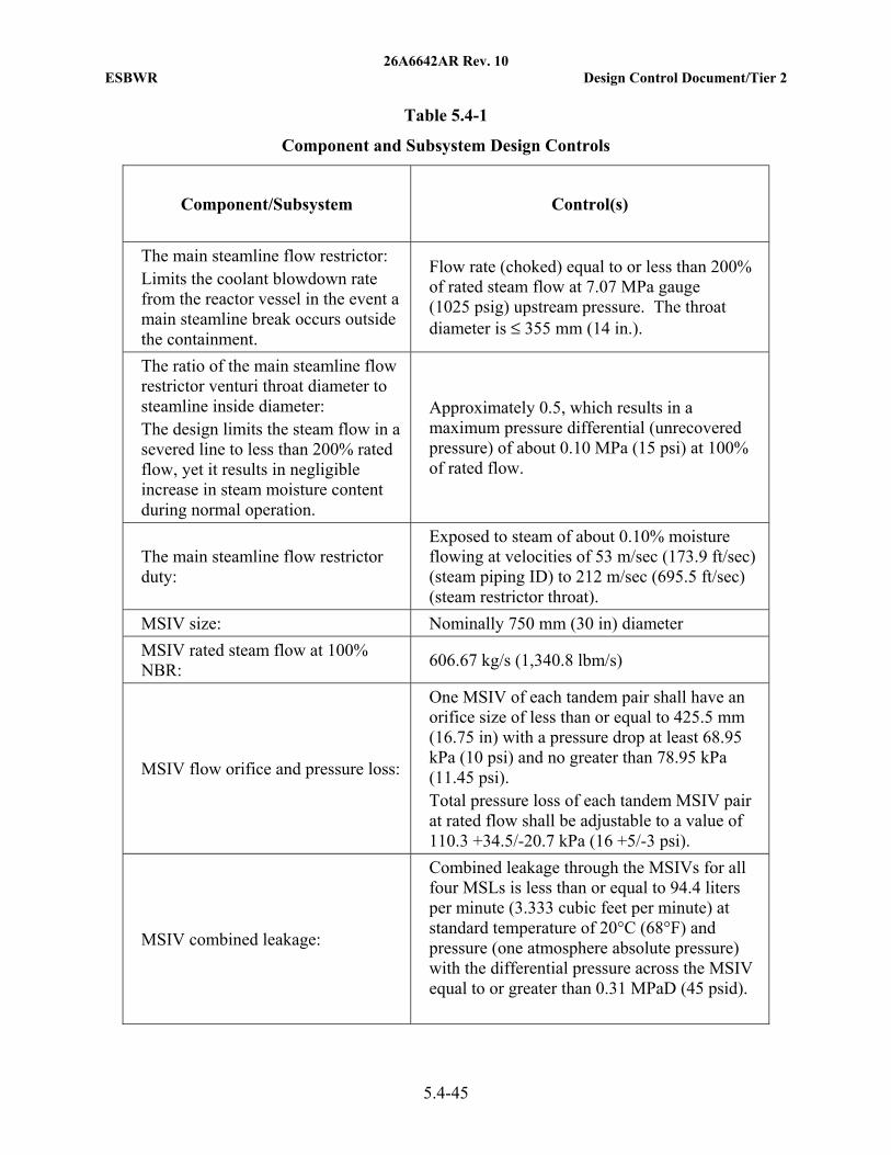
26A6642AR Rev. 10 ESBWR Design Control Document/Tier 2
5.4-45
Table 5.4-1
Component and Subsystem Design Controls
Component/Subsystem Control(s)
The main steamline flow restrictor: Limits the coolant blowdown rate from the reactor vessel in the event a main steamline break occurs outside the containment.
Flow rate (choked) equal to or less than 200% of rated steam flow at 7.07 MPa gauge (1025 psig) upstream pressure. The throat diameter is ≤ 355 mm (14 in.).
The ratio of the main steamline flow restrictor venturi throat diameter to steamline inside diameter: The design limits the steam flow in a severed line to less than 200% rated flow, yet it results in negligible increase in steam moisture content during normal operation.
Approximately 0.5, which results in a maximum pressure differential (unrecovered pressure) of about 0.10 MPa (15 psi) at 100% of rated flow.
The main steamline flow restrictor duty:
Exposed to steam of about 0.10% moisture flowing at velocities of 53 m/sec (173.9 ft/sec) (steam piping ID) to 212 m/sec (695.5 ft/sec) (steam restrictor throat).
MSIV size: Nominally 750 mm (30 in) diameter
MSIV rated steam flow at 100% NBR:
606.67 kg/s (1,340.8 lbm/s)
MSIV flow orifice and pressure loss:
One MSIV of each tandem pair shall have an orifice size of less than or equal to 425.5 mm (16.75 in) with a pressure drop at least 68.95 kPa (10 psi) and no greater than 78.95 kPa (11.45 psi). Total pressure loss of each tandem MSIV pair at rated flow shall be adjustable to a value of 110.3 +34.5/-20.7 kPa (16 +5/-3 psi).
MSIV combined leakage:
Combined leakage through the MSIVs for all four MSLs is less than or equal to 94.4 liters per minute (3.333 cubic feet per minute) at standard temperature of 20°C (68°F) and pressure (one atmosphere absolute pressure) with the differential pressure across the MSIV equal to or greater than 0.31 MPaD (45 psid).
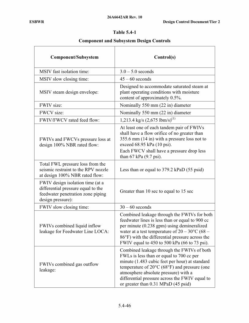
26A6642AR Rev. 10 ESBWR Design Control Document/Tier 2
5.4-46
Table 5.4-1
Component and Subsystem Design Controls
Component/Subsystem Control(s)
MSIV fast isolation time: 3.0 – 5.0 seconds
MSIV slow closing time: 45 – 60 seconds
MSIV steam design envelope: Designed to accommodate saturated steam at plant operating conditions with moisture content of approximately 0.5%.
FWIV size: Nominally 550 mm (22 in) diameter
FWCV size: Nominally 550 mm (22 in) diameter
FWIV/FWCV rated feed flow: 1,213.4 kg/s (2,675 lbm/s)(1)
FWIVs and FWCVs pressure loss at design 100% NBR rated flow:
At least one of each tandem pair of FWIVs shall have a flow orifice of no greater than 355.6 mm (14 in) with a pressure loss not to exceed 68.95 kPa (10 psi). Each FWCV shall have a pressure drop less than 67 kPa (9.7 psi).
Total FWL pressure loss from the seismic restraint to the RPV nozzle at design 100% NBR rated flow:
Less than or equal to 379.2 kPaD (55 psid)
FWIV design isolation time (at a differential pressure equal to the feedwater penetration zone piping design pressure):
Greater than 10 sec to equal to 15 sec
FWIV slow closing time: 30 – 60 seconds
FWIVs combined liquid inflow leakage for Feedwater Line LOCA:
Combined leakage through the FWIVs for both feedwater lines is less than or equal to 900 cc per minute (0.238 gpm) using demineralized water at a test temperature of 20 – 30°C (68 – 86°F) with the differential pressure across the FWIV equal to 450 to 500 kPa (66 to 73 psi).
FWIVs combined gas outflow leakage:
Combined leakage through the FWIVs of both FWLs is less than or equal to 700 cc per minute (1.483 cubic feet per hour) at standard temperature of 20°C (68°F) and pressure (one atmosphere absolute pressure) with a differential pressure across the FWIV equal to or greater than 0.31 MPaD (45 psid)
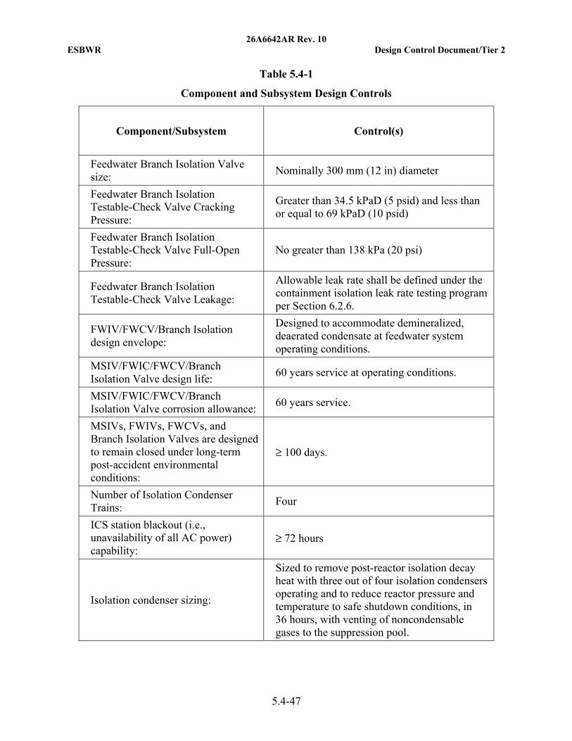
26A6642AR Rev. 10 ESBWR Design Control Document/Tier 2
5.4-47
Table 5.4-1
Component and Subsystem Design Controls
Component/Subsystem Control(s)
Feedwater Branch Isolation Valve size:
Nominally 300 mm (12 in) diameter
Feedwater Branch Isolation Testable-Check Valve Cracking Pressure:
Greater than 34.5 kPaD (5 psid) and less than or equal to 69 kPaD (10 psid)
Feedwater Branch Isolation Testable-Check Valve Full-Open Pressure:
No greater than 138 kPa (20 psi)
Feedwater Branch Isolation Testable-Check Valve Leakage:
Allowable leak rate shall be defined under the containment isolation leak rate testing program per Section 6.2.6.
FWIV/FWCV/Branch Isolation design envelope:
Designed to accommodate demineralized, deaerated condensate at feedwater system operating conditions.
MSIV/FWIC/FWCV/Branch Isolation Valve design life:
60 years service at operating conditions.
MSIV/FWIC/FWCV/Branch Isolation Valve corrosion allowance:
60 years service.
MSIVs, FWIVs, FWCVs, and Branch Isolation Valves are designed to remain closed under long-term post-accident environmental conditions:
≥ 100 days.
Number of Isolation Condenser Trains:
Four
ICS station blackout (i.e., unavailability of all AC power) capability:
≥ 72 hours
Isolation condenser sizing:
Sized to remove post-reactor isolation decay heat with three out of four isolation condensers operating and to reduce reactor pressure and temperature to safe shutdown conditions, in 36 hours, with venting of noncondensable gases to the suppression pool.
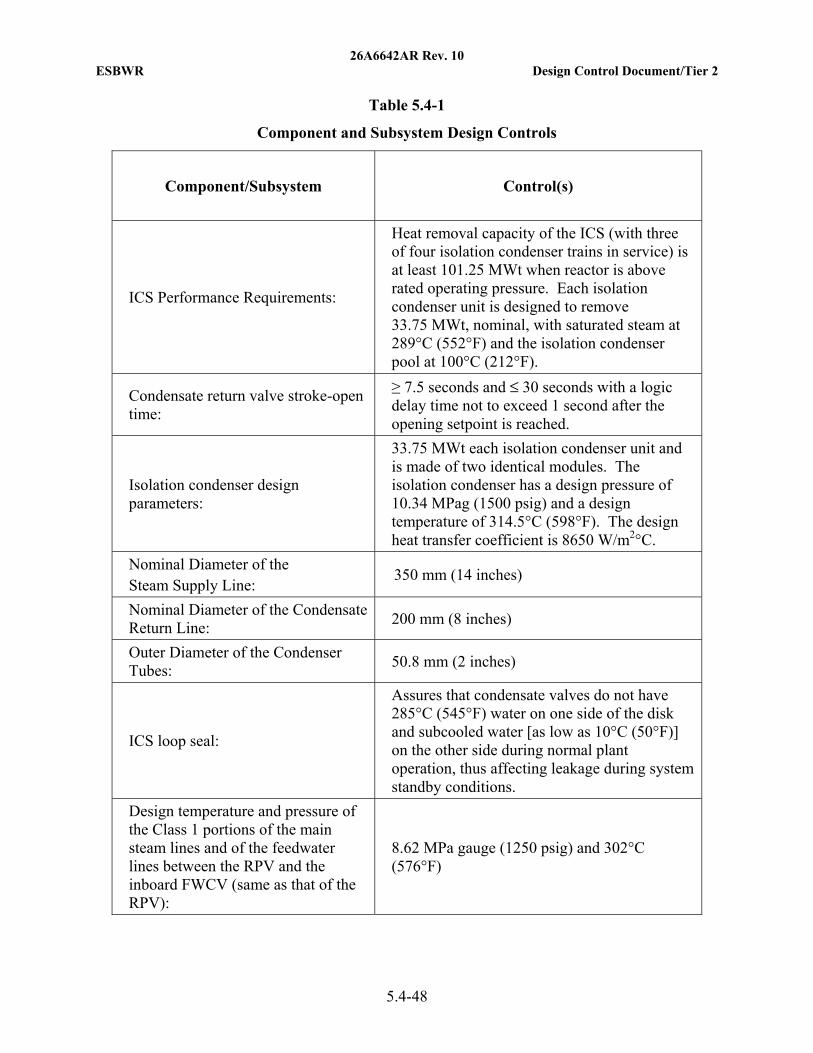
26A6642AR Rev. 10 ESBWR Design Control Document/Tier 2
5.4-48
Table 5.4-1
Component and Subsystem Design Controls
Component/Subsystem Control(s)
ICS Performance Requirements:
Heat removal capacity of the ICS (with three of four isolation condenser trains in service) is at least 101.25 MWt when reactor is above rated operating pressure. Each isolation condenser unit is designed to remove 33.75 MWt, nominal, with saturated steam at 289°C (552°F) and the isolation condenser pool at 100°C (212°F).
Condensate return valve stroke-open time:
≥ 7.5 seconds and ≤ 30 seconds with a logic delay time not to exceed 1 second after the opening setpoint is reached.
Isolation condenser design parameters:
33.75 MWt each isolation condenser unit and is made of two identical modules. The isolation condenser has a design pressure of 10.34 MPag (1500 psig) and a design temperature of 314.5°C (598°F). The design heat transfer coefficient is 8650 W/m2°C.
Nominal Diameter of the Steam Supply Line:
350 mm (14 inches)
Nominal Diameter of the Condensate Return Line:
200 mm (8 inches)
Outer Diameter of the Condenser Tubes:
50.8 mm (2 inches)
ICS loop seal:
Assures that condensate valves do not have 285°C (545°F) water on one side of the disk and subcooled water [as low as 10°C (50°F)] on the other side during normal plant operation, thus affecting leakage during system standby conditions.
Design temperature and pressure of the Class 1 portions of the main steam lines and of the feedwater lines between the RPV and the inboard FWCV (same as that of the RPV):
8.62 MPa gauge (1250 psig) and 302°C (576°F)
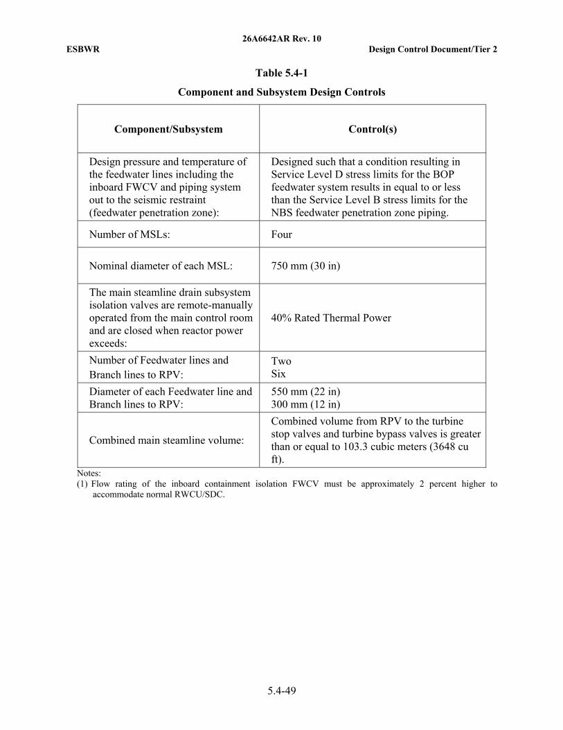
26A6642AR Rev. 10 ESBWR Design Control Document/Tier 2
5.4-49
Table 5.4-1
Component and Subsystem Design Controls
Component/Subsystem Control(s)
Design pressure and temperature of the feedwater lines including the inboard FWCV and piping system out to the seismic restraint (feedwater penetration zone):
Designed such that a condition resulting in Service Level D stress limits for the BOP feedwater system results in equal to or less than the Service Level B stress limits for the NBS feedwater penetration zone piping.
Number of MSLs: Four
Nominal diameter of each MSL: 750 mm (30 in)
The main steamline drain subsystem isolation valves are remote-manually operated from the main control room and are closed when reactor power exceeds:
40% Rated Thermal Power
Number of Feedwater lines and Branch lines to RPV:
Two Six
Diameter of each Feedwater line andBranch lines to RPV:
550 mm (22 in) 300 mm (12 in)
Combined main steamline volume:
Combined volume from RPV to the turbine stop valves and turbine bypass valves is greater than or equal to 103.3 cubic meters (3648 cu ft).
Notes: (1) Flow rating of the inboard containment isolation FWCV must be approximately 2 percent higher to
accommodate normal RWCU/SDC.

26A6642AR Rev. 10 ESBWR Design Control Document/Tier 2
5.4-50
Table 5.4-2
(Deleted)
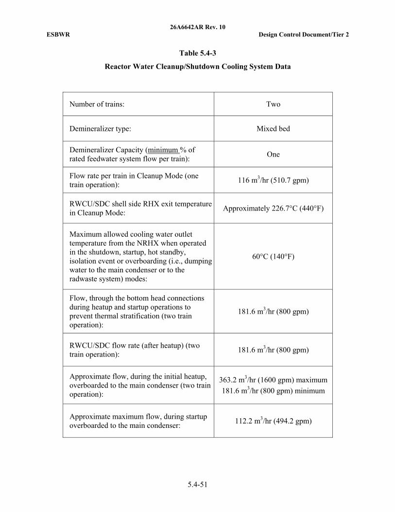
26A6642AR Rev. 10 ESBWR Design Control Document/Tier 2
5.4-51
Table 5.4-3
Reactor Water Cleanup/Shutdown Cooling System Data
Number of trains: Two
Demineralizer type: Mixed bed
Demineralizer Capacity (minimum % of rated feedwater system flow per train):
One
Flow rate per train in Cleanup Mode (one train operation):
116 m3/hr (510.7 gpm)
RWCU/SDC shell side RHX exit temperature in Cleanup Mode:
Approximately 226.7°C (440°F)
Maximum allowed cooling water outlet temperature from the NRHX when operated in the shutdown, startup, hot standby, isolation event or overboarding (i.e., dumping water to the main condenser or to the radwaste system) modes:
60°C (140°F)
Flow, through the bottom head connections during heatup and startup operations to prevent thermal stratification (two train operation):
181.6 m3/hr (800 gpm)
RWCU/SDC flow rate (after heatup) (two train operation):
181.6 m3/hr (800 gpm)
Approximate flow, during the initial heatup, overboarded to the main condenser (two train operation):
363.2 m3/hr (1600 gpm) maximum
181.6 m3/hr (800 gpm) minimum
Approximate maximum flow, during startup overboarded to the main condenser:
112.2 m3/hr (494.2 gpm)
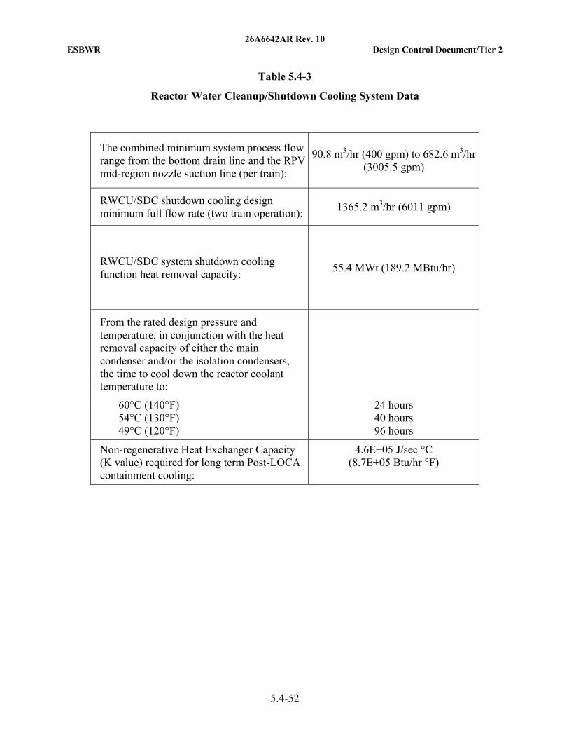
26A6642AR Rev. 10 ESBWR Design Control Document/Tier 2
5.4-52
Table 5.4-3
Reactor Water Cleanup/Shutdown Cooling System Data
The combined minimum system process flow range from the bottom drain line and the RPV mid-region nozzle suction line (per train):
90.8 m3/hr (400 gpm) to 682.6 m3/hr (3005.5 gpm)
RWCU/SDC shutdown cooling design minimum full flow rate (two train operation):
1365.2 m3/hr (6011 gpm)
RWCU/SDC system shutdown cooling function heat removal capacity:
55.4 MWt (189.2 MBtu/hr)
From the rated design pressure and temperature, in conjunction with the heat removal capacity of either the main condenser and/or the isolation condensers, the time to cool down the reactor coolant temperature to:
60°C (140°F) 54°C (130°F) 49°C (120°F)
24 hours 40 hours 96 hours
Non-regenerative Heat Exchanger Capacity (K value) required for long term Post-LOCA containment cooling:
4.6E+05 J/sec °C (8.7E+05 Btu/hr °F)
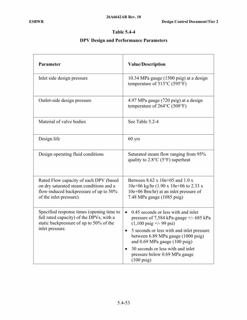
26A6642AR Rev. 10 ESBWR Design Control Document/Tier 2
5.4-53
Table 5.4-4
DPV Design and Performance Parameters
Parameter Value/Description
Inlet side design pressure 10.34 MPa gauge (1500 psig) at a design temperature of 313°C (595°F)
Outlet-side design pressure 4.97 MPa gauge (720 psig) at a design temperature of 264°C (508°F)
Material of valve bodies See Table 5.2-4
Design life 60 yrs
Design operating fluid conditions Saturated steam flow ranging from 95% quality to 2.8°C (5°F) superheat
Rated Flow capacity of each DPV (based on dry saturated steam conditions and a flow-induced backpressure of up to 50% of the inlet pressure).
Between 8.62 x 10e+05 and 1.0 x 10e+06 kg/hr (1.90 x 10e+06 to 2.33 x 10e+06 lbm/hr) at an inlet pressure of 7.48 MPa gauge (1085 psig)
Specified response times (opening time to full rated capacity) of the DPVs, with a static backpressure of up to 50% of the inlet pressure.
• 0.45 seconds or less with and inlet pressure of 7,584 kPa-gauge +/- 685 kPa (1,100 psig +/- 99 psi)
• 5 seconds or less with and inlet pressure between 6.89 MPa gauge (1000 psig) and 0.69 MPa gauge (100 psig)
• 30 seconds or less with and inlet pressure below 0.69 MPa gauge (100 psig)
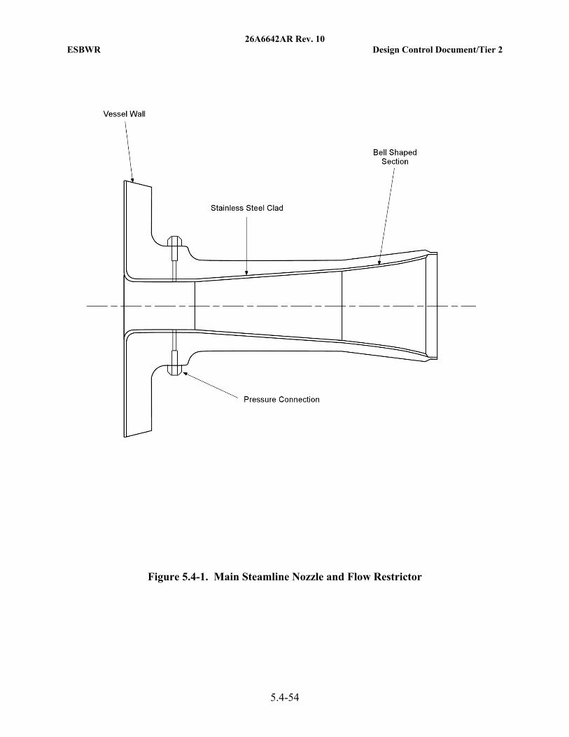
26A6642AR Rev. 10 ESBWR Design Control Document/Tier 2
5.4-54
Figure 5.4-1. Main Steamline Nozzle and Flow Restrictor
26A6642AR Rev. 10 ESBWR Design Control Document/Tier 2
5.4-55
Figure 5.4-2. (Deleted)
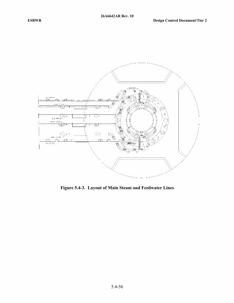
26A6642AR Rev. 10 ESBWR Design Control Document/Tier 2
5.4-56
Figure 5.4-3. Layout of Main Steam and Feedwater Lines
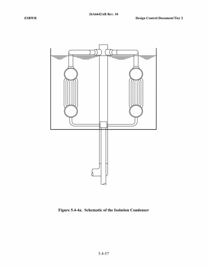
26A6642AR Rev. 10 ESBWR Design Control Document/Tier 2
5.4-57
Figure 5.4-4a. Schematic of the Isolation Condenser
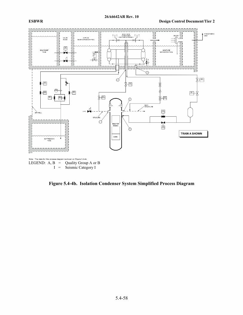
26A6642AR Rev. 10 ESBWR Design Control Document/Tier 2
5.4-58
LEGEND: A, B = Quality Group A or B
I = Seismic Category I
Figure 5.4-4b. Isolation Condenser System Simplified Process Diagram
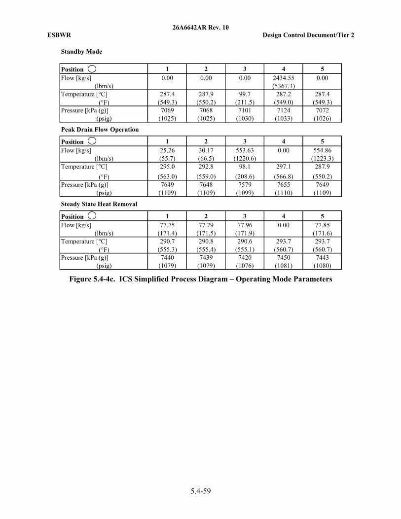
26A6642AR Rev. 10 ESBWR Design Control Document/Tier 2
5.4-59
Figure 5.4-4c. ICS Simplified Process Diagram – Operating Mode Parameters
Standby Mode
Position 1 2 3 4 5Flow [kg/s] 2434.55
(lbm/s) (5367.3)Temperature [°C] 287.4 287.9 99.7 287.2 287.4
(°F) (549.3) (550.2) (211.5) (549.0) (549.3)Pressure [kPa (g)] 7069 7068 7101 7124 7072
(psig) (1025) (1025) (1030) (1033) (1026)
Peak Drain Flow Operation
Position 1 2 3 4 5Flow [kg/s] 25.26 30.17 553.63 554.86
(lbm/s) (55.7) (66.5) (1220.6) (1223.3)Temperature [°C] 295.0 292.8 98.1 297.1 287.9
(°F) (563.0) (559.0) (208.6) (566.8) (550.2)Pressure [kPa (g)] 7649 7648 7579 7655 7649
(psig) (1109) (1109) (1099) (1110) (1109)
Steady State Heat Removal
Position 1 2 3 4 5Flow [kg/s] 77.75 77.79 77.96 77.85
(lbm/s) (171.4) (171.5) (171.9) (171.6)Temperature [°C] 290.7 290.8 290.6 293.7 293.7
(°F) (555.3) (555.4) (555.1) (560.7) (560.7)Pressure [kPa (g)] 7440 7439 7420 7450 7443
(psig) (1079) (1079) (1076) (1081) (1080)
0.00
0.00
0.00
0.00 0.00 0.00
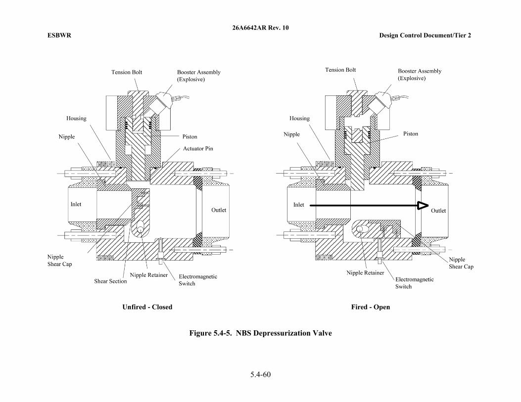
26A6642AR Rev. 10 ESBWR Design Control Document/Tier 2
5.4-60
Figure 5.4-5. NBS Depressurization Valve