Embed Size (px)
Citation preview
INSTITUTE OF PHYSICS PUBLISHING and INTERNATIONAL ATOMIC ENERGY AGENCY NUCLEAR FUSION
Nucl. Fusion 46 (2006) S192–S198 doi:10.1088/0029-5515/46/4/S11
Escaping and transport barrier due toergodic magnetic limiters in tokamakswith reversed magnetic shearElton C. da Silva1, Marisa Roberto2, Jefferson S.E. Portela1,Ibere L. Caldas1 and Ricardo L. Viana3
1 Instituto de Fısica, Universidade de Sao Paulo, C.P. 66318, 05315-970, Sao Paulo,Sao Paulo, Brazil2 Instituto Tecnologico de Aeronautica, Centro Tecnico Aeroespacial, Departamento deFısica, 12228-900, São Jose dos Campos, Sao Paulo, Brazil3 Departamento de Fısica, Universidade Federal do Parana, C.P . 19081, 81531-990, Curitiba,Parana, Brazil
E-mail: [email protected]
Received 5 August 2005, accepted for publication 28 February 2006Published 21 March 2006Online at stacks.iop.org/NF/46/S192
AbstractAnalytical tokamak plasma equilibria, with non-monotonic plasma current profile and perturbed by ergodic magneticlimiters, are described by non-twist conservative maps. Examples are given of concentration of magnetic field linesescaping to the tokamak wall. The robustness of invariant curves on the shearless region is also observed.
PACS numbers: 05.45.Ac, 05.45.Pq, 52.25.Fi
1. Introduction
The presence of non-integrable magnetic field lines in a certainplasma region within the tokamak implies the loss of theplasma confinement, due to the absence of flux surfaces.However, the chaotization of a limited plasma region, ifproperly handled, can be beneficial to the plasma confinement,as exemplified by the ergodic magnetic limiter [1–5] and theDynamic Ergodic Divertor at TEXTOR tokamak [6]. Anothersituation in which the presence of non-integrable magneticfields can help plasma confinement is the creation of a barrierto reduce Lagrangian field line escape in tokamaks with anegative magnetic shear region. Such a region is created bymeans of a non-peaked plasma current density, correspondingto a non-monotonic radial profile for the safety factor [7]. Aresonant magnetic perturbation in the shearless region givesrise to a barrier separating the internal region with magneticsurfaces from the external stochastic region. The field lineescape outside the barrier, at the plasma edge, is similar tothose observed for monotonic equilibria. In fact, outsidethe barrier, the safety factor increases monotonically. Thepresence of the Lagrangian barrier in the shearless regionlimits the volume of the escape region. All this maycontribute to the enhanced plasma confinement which hasbeen observed in some experiments with magnetic shearlessequilibria [8, 9].
Unlike most magnetic configurations, negative shearconfigurations are best described by non-twist area-preservingmaps [10, 11]. Such maps violate the non-degeneracycondition for the Kolmogorov–Arnold–Moser (KAM) theoremto be valid, so that many well-known results of canonicalmappings no longer apply to them [12–14]. For example, itmay happen that two neighbour island chains approach eachother without being destroyed through the breakup of KAMcurves [15]. The transport barrier arises from a combinationof typical features of non-twist maps: reconnection andbifurcation, occurring in the reversed shear region [16]. Thisbarrier is embedded in a chaotic field line region located inthe tokamak peripheral region. Further investigation of thisbarrier requires a conservative map like the ones used in thisarticle.
In this paper we introduce non-twist maps obtained byconsidering the superposition of an ergodic magnetic limiterfield on the tokamak equilibrium field with a negative shearregion due to a non-peaked plasma current. The limiterperturbation generates resonant magnetic fields that interactwith the equilibrium field, causing a selective destruction ofthe magnetic surfaces at the plasma edge. On the inner plasmaregion, the field lines lie on magnetic surfaces, while thechaotic and unstable periodic lines are in the outer scrape-offlayer. The external chaotic layer configuration is essentially
0029-5515/06/040192+07$30.00 © 2006 IAEA, Vienna Printed in the UK S192
Escaping and transport barrier
determined by the chaotic set on the scrape-off layer [17–21].As a consequence of this chaotic configuration, the fieldlines with long connection lengths hit the tokamak wall non-uniformly producing the so-called field line escape pattern.
In this work, we use one of the introduced non-twist mapsto study the connection of the chaotic lines to the tokamakwall. These maps are also used to numerically evidencethe formation of a transport barrier due to a reconnection–bifurcation mechanism, and its effect on the plasma transportcan be inferred from the study of field line diffusion by usingthe obtained maps.
The paper is organized as follows: in section 2, wepresent an area-preserving non-twist map to study, in toroidalgeometry, the field line escaping to the tokamak wall. Insection 3, we introduce another symplectic non-twist map tostudy the robustness of the internal shearless barriers in largeaspect ratio tokamaks. Our conclusions are presented in thelast section.
2. Field line escaping
In this section, we study the Lagrangian field line transport andthe line escaping to the tokamak wall for a plasma equilibriumwith reversed magnetic shear. We use a suitable coordinatesystem to describe magnetic field line geometry in a tokamak:(rt , θt , ϕt ), given by [22]
rt = R′0
cosh(ξ) − cos(ω), (1)
θt = π − ω, (2)
ϕt = �, (3)
in terms of the usual toroidal coordinates (ξ, ω, �) as presentedin [23]. The meaning of these variables is the following: rt isrelated to the radial coordinate of a field line with respect tothe magnetic axis. R′
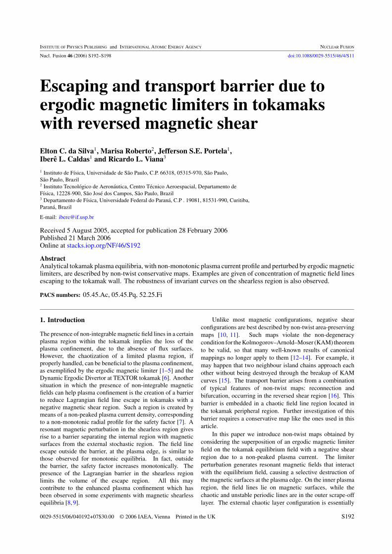
0 is the major radius with respect to themagnetic axis. R0 and b are (see figure 1(a)), respectively,the major and minor radii with respect to the geometric axis.The angles θt and ϕt are, respectively, the poloidal and toroidalangles of this field line.
The contravariant components of the tokamak equilibriummagnetic field B0 = (0, B
(2)0 , B
(3)0 ) are obtained from an
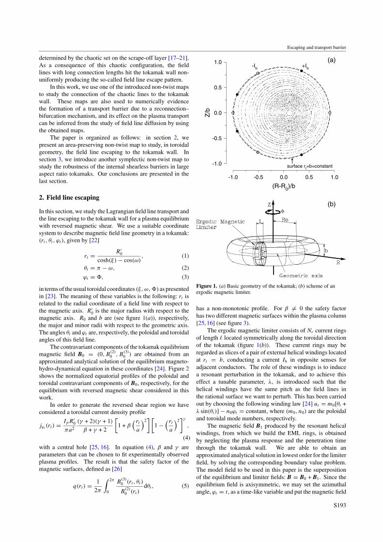
approximated analytical solution of the equilibrium magneto-hydro-dynamical equation in these coordinates [24]. Figure 2shows the normalized equatorial profiles of the poloidal andtoroidal contravariant components of B0, respectively, for theequilibrium with reversed magnetic shear considered in thiswork.
In order to generate the reversed shear region we haveconsidered a toroidal current density profile
jϕt(rt ) = IpR′
0
πa2
(γ + 2)(γ + 1)
β + γ + 2
[1 + β
( rt
a
)2] [
1 −( rt
a
)2]γ
,
(4)
with a central hole [25, 16]. In equation (4), β and γ areparameters that can be chosen to fit experimentally observedplasma profiles. The result is that the safety factor of themagnetic surfaces, defined as [26]
q(rt ) = 1
2π
∫ 2π
0
B(3)0 (rt , θt )
B(2)0 (rt )
dθt , (5)
-1.0 -0.5 0.0 0.5 1.0
(R-R0)/b
-1.0
-0.5
0.0
0.5
1.0
Z/b
-Ih +Ih
surface rt=b=constant
(a)
(b)
Figure 1. (a) Basic geometry of the tokamak; (b) scheme of anergodic magnetic limiter.
has a non-monotonic profile. For β �= 0 the safety factorhas two different magnetic surfaces within the plasma column[25, 16] (see figure 3).
The ergodic magnetic limiter consists of Nr current ringsof length located symmetrically along the toroidal directionof the tokamak (figure 1(b)). These current rings may beregarded as slices of a pair of external helical windings locatedat rt = b, conducting a current Ih in opposite senses foradjacent conductors. The role of these windings is to inducea resonant perturbation in the tokamak, and to achieve thiseffect a tunable parameter, λ, is introduced such that thehelical windings have the same pitch as the field lines inthe rational surface we want to perturb. This has been carriedout by choosing the following winding law [24] ut = m0[θt +λ sin(θt )] − n0ϕt = constant, where (m0, n0) are the poloidaland toroidal mode numbers, respectively.
The magnetic field B1 produced by the resonant helicalwindings, from which we build the EML rings, is obtainedby neglecting the plasma response and the penetration timethrough the tokamak wall. We are able to obtain anapproximated analytical solution in lowest order for the limiterfield, by solving the corresponding boundary value problem.The model field to be used in this paper is the superpositionof the equilibrium and limiter fields: B = B0 + B1. Since theequilibrium field is axisymmetric, we may set the azimuthalangle, ϕt = t , as a time-like variable and put the magnetic field
S193
E.C. da Silva et al
-1.0 -0.5 0.0 0.5 1.0
(R-R0)/a
0.8
0.9
1.0
1.1
1.2
B(2
) /Ba
-1.0 -0.5 0.0 0.5 1.0
(R-R0)/a
0.5
1.0
1.5
2.0
2.5
B(3
) /BT
(a)
(b)
Figure 2. Profiles of the poloidal (a) and toroidal (b) contravariantcomponents of the equilibrium magnetic field with reversedshear.
0.00 0.01 0.02 0.03 0.04
I
3.6
4.0
4.4
4.8
5.2
q(I)
Figure 3. Profile of the safety factor for a reversed shearconfiguration of a tokamak in terms of the action variable.
line equations in a Hamiltonian form [27]
dIdt
= − ∂H
∂ϑ, (6)
dϑ
dt= ∂H
∂I, (7)
where (I, ϑ) are the action–angle variables of a HamiltonianH , its explicit form being given by
I(rt ) = 1
4
[1 − +(rt ) · −(rt )
], (8)
ϑ(rt , θt ) = 2 arctan
[ +(rt )
−(rt )tan
(θt
2
)], (9)
where
±(rt ) =√
1 ± 2rt
R′0
. (10)
The addition of the magnetic field produced byresonant helical windings may be regarded as a Hamiltonianperturbation. In order to include the effect of the finite length of each EML ring, which is typically a small fraction of thetotal toroidal circumference 2πR′
0, we model its effect as asequence of delta-functions centred at each ring position. TheHamiltonian for the system is thus
H(I, ϑ, t) = H0(I) + εH1(I, ϑ, t)
+∞∑k=−∞
δ
(t − k
2π
Nr
),
(11)
where
H0(I)=∫
2πdIq(rt (I))
and H1(I, ϑ, t)=2m0∑m=0
H ∗m(I)ei(mϑ−n0t),
(12)
with
H ∗m(I) =
2m0∑m′=0
Hm′(rt (I)) · Sm,m′(I), (13)
Hm′(rt ) = −Jm′−m0(m0λ)( rt
b
)m′
, (14)
Sm,m′(I) = 1
2π
∫ 2π
0ei[m′θt (I,ϑ)−mϑ]dϑ. (15)
Due to the t-dependence of the Hamiltonian in the formof a sequence of delta-functions, it is possible to definediscretized variables (In, ϑn) as the corresponding valuesof the angle–action variables just after the nth crossing ofa field line with the plane tk = (2πk/Nr) with k =0, 1, 2, . . . , Nr − 1 [28]. Proceeding in this fashion, thefollowing area-preserving mapping can be associated with theEML Hamiltonian (equation (11)) [24]:
In+1 = In + εf (In+1, ϑn, tn), (16)
ϑn+1 = ϑn +2π
Nrq(In+1)+ εg(In+1, ϑn, tn), (17)
tn+1 = tn +2π
Nr
, (18)
with
f = −∂H1
∂ϑ, g = ∂H1
∂Iand ε = 2
Ihl
IeR′0
,
(19)where l is the EML coil width and Ie is the total current on thesolenoid that creates the toroidal magnetic field.
It should be remarked, however, that the integrationalong the delta functions is not well defined. A more exact
S194
Escaping and transport barrier
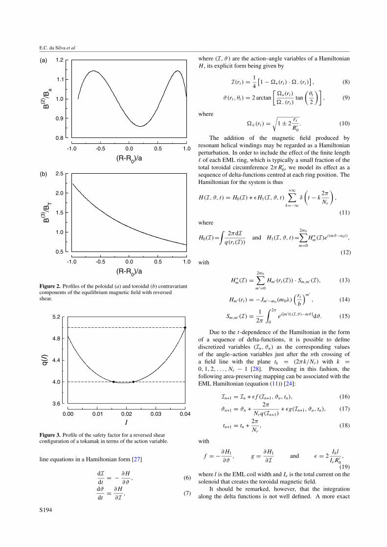
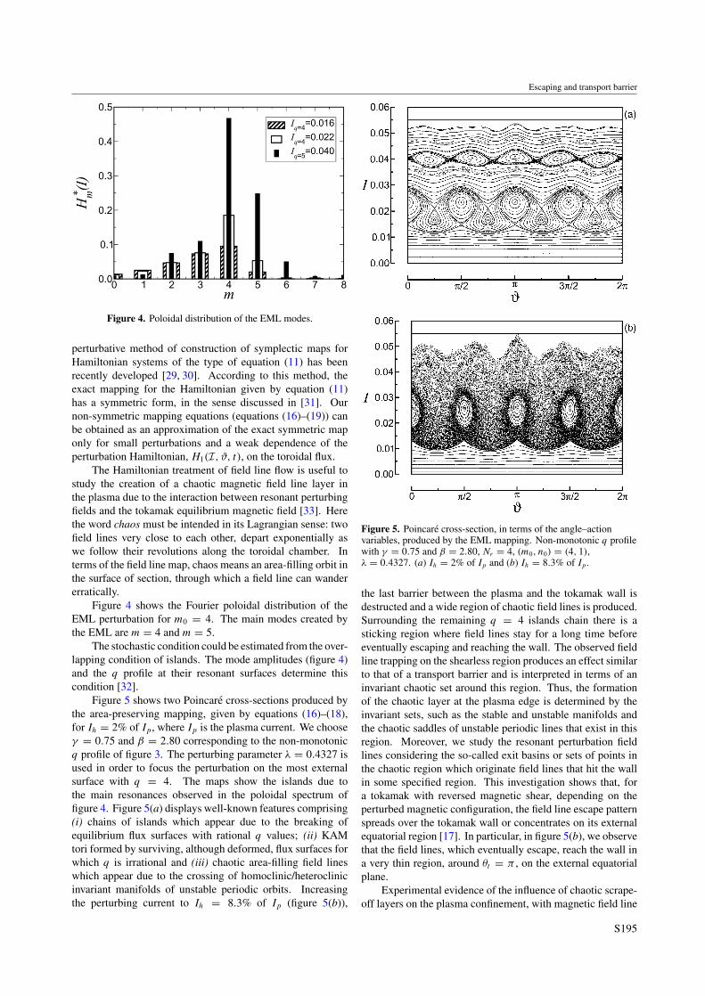
Figure 4. Poloidal distribution of the EML modes.
perturbative method of construction of symplectic maps forHamiltonian systems of the type of equation (11) has beenrecently developed [29, 30]. According to this method, theexact mapping for the Hamiltonian given by equation (11)has a symmetric form, in the sense discussed in [31]. Ournon-symmetric mapping equations (equations (16)–(19)) canbe obtained as an approximation of the exact symmetric maponly for small perturbations and a weak dependence of theperturbation Hamiltonian, H1(I, ϑ, t), on the toroidal flux.
The Hamiltonian treatment of field line flow is useful tostudy the creation of a chaotic magnetic field line layer inthe plasma due to the interaction between resonant perturbingfields and the tokamak equilibrium magnetic field [33]. Herethe word chaos must be intended in its Lagrangian sense: twofield lines very close to each other, depart exponentially aswe follow their revolutions along the toroidal chamber. Interms of the field line map, chaos means an area-filling orbit inthe surface of section, through which a field line can wandererratically.
Figure 4 shows the Fourier poloidal distribution of theEML perturbation for m0 = 4. The main modes created bythe EML are m = 4 and m = 5.
The stochastic condition could be estimated from the over-lapping condition of islands. The mode amplitudes (figure 4)and the q profile at their resonant surfaces determine thiscondition [32].
Figure 5 shows two Poincare cross-sections produced bythe area-preserving mapping, given by equations (16)–(18),for Ih = 2% of Ip, where Ip is the plasma current. We chooseγ = 0.75 and β = 2.80 corresponding to the non-monotonicq profile of figure 3. The perturbing parameter λ = 0.4327 isused in order to focus the perturbation on the most externalsurface with q = 4. The maps show the islands due tothe main resonances observed in the poloidal spectrum offigure 4. Figure 5(a) displays well-known features comprising(i) chains of islands which appear due to the breaking ofequilibrium flux surfaces with rational q values; (ii) KAMtori formed by surviving, although deformed, flux surfaces forwhich q is irrational and (iii) chaotic area-filling field lineswhich appear due to the crossing of homoclinic/heteroclinicinvariant manifolds of unstable periodic orbits. Increasingthe perturbing current to Ih = 8.3% of Ip (figure 5(b)),
Figure 5. Poincare cross-section, in terms of the angle–actionvariables, produced by the EML mapping. Non-monotonic q profilewith γ = 0.75 and β = 2.80, Nr = 4, (m0, n0) = (4, 1),λ = 0.4327. (a) Ih = 2% of Ip and (b) Ih = 8.3% of Ip .
the last barrier between the plasma and the tokamak wall isdestructed and a wide region of chaotic field lines is produced.Surrounding the remaining q = 4 islands chain there is asticking region where field lines stay for a long time beforeeventually escaping and reaching the wall. The observed fieldline trapping on the shearless region produces an effect similarto that of a transport barrier and is interpreted in terms of aninvariant chaotic set around this region. Thus, the formationof the chaotic layer at the plasma edge is determined by theinvariant sets, such as the stable and unstable manifolds andthe chaotic saddles of unstable periodic lines that exist in thisregion. Moreover, we study the resonant perturbation fieldlines considering the so-called exit basins or sets of points inthe chaotic region which originate field lines that hit the wallin some specified region. This investigation shows that, fora tokamak with reversed magnetic shear, depending on theperturbed magnetic configuration, the field line escape patternspreads over the tokamak wall or concentrates on its externalequatorial region [17]. In particular, in figure 5(b), we observethat the field lines, which eventually escape, reach the wall ina very thin region, around θt = π , on the external equatorialplane.
Experimental evidence of the influence of chaotic scrape-off layers on the plasma confinement, with magnetic field line
S195
E.C. da Silva et al
shear, have been recently reported [18, 34]. This evidenceconfirms the importance of invariant chaotic saddles to predictthe scrape-off layer magnetic structures [19–21].
3. Transport barrier
The basic geometry of a tokamak is determined by its major(R0) and minor (b) radii (figure 1(a)). When the tokamakaspect ratio R0/b is large enough we can neglect, in a zerothapproximation, the effects of the toroidal curvature and treat itas a periodic cylinder of length 2πR0, whose axis of symmetryis parametrized by the coordinate z = R0ϕ in terms of thetoroidal angle ϕ [26]. In this case, the equilibrium toroidal fieldB0 is practically uniform. Accordingly, a point in the tokamakis located by its cylindrical coordinates (r, θ, z) with respect tothat axis. On the other hand, in the study of the region near thetokamak wall, it turns out that even the poloidal curvature doesnot change results noticeably, so that a rectangular system canbe found by defining the following coordinates: x ′ = bθ andy ′ = b − r [35]. The tokamak wall is thus characterized bythe line segment y ′ = 0 extending from x ′ = 0 to 2πb. In thefollowing we will use normalized coordinates x = x ′/b andy = y ′/b.
In the description used in this section the structure ofthe magnetic field lines in a tokamak can be more easilyappreciated by taking a Poincare surface of section at the planez = 0. Let (rn, θn) be the polar coordinates of the nth piercingof a given field line with that surface. Since the magneticfield line equations determine uniquely the position of the nextpiercing, we have a Poincare map (rn+1, θn+1)
T = F1(rn, θn)T .
Due to the solenoidal character of the magnetic field, this mapis area-preserving in the surface of section [36]. The regularorbits lay in invariants magnetic surfaces described by theequation
r dϕ
R0 dθ= q, (20)
where θ and ϕ are the angles on the surface identified by thesafety factor q.
In the absence of any perturbation, the configuration isdescribed by a map (r∗
n , θ∗n )T = F1(rn, θn)
T [37], where
r∗n = rn
1 − a1 sin θn
, (21)
θ∗n = θn +
2π
q(r∗n )
+ a1 cos θn, (22)
which have a correction for the effect of the toroidal curvaturewhose strength is given by the a1 parameter.
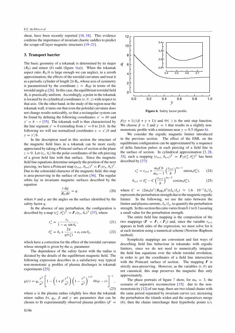
The dependence of the safety factor with the radius isdictated by the details of the equilibrium magnetic field. Thefollowing expression describes in a satisfactory way typicalnon-monotonic q profiles of plasma discharges in tokamakexperiments [25]:
q(r) = qa
r2
a2
[1 −
(1 + β ′ r
2
a2
) (1 − r2
a2
)γ +1
�(a − r)
]−1
,
(23)where a is the plasma radius (slightly less then the tokamakminor radius b), qa , β and γ are parameters that can bechosen to fit experimentally observed plasma profiles (β ′ =
0.0 0.2 0.4 0.6 0. .0y
0
2
4
6
8
10
12
q
0.4 0.5 0.6 0.7
2.8
3.0
3.2
3.4
Figure 6. Safety factor profile.
β(γ + 1)/(β + γ + 1)) and �( · ) is the unit step function.We choose β = 2 and γ = 1 that results in a slightly non-monotonic profile with a minimum near y = 0.5 (figure 6).
We consider the ergodic magnetic limiter introducedin the previous section. The effect of the EML on theequilibrium configuration can be approximated by a sequenceof delta function pulses at each piercing of a field line inthe surface of section. In cylindrical approximation [3, 28,35], such a mapping (rn+1, θn+1)
T = F2(r∗n , θ∗
n )T has beendescribed by [37]:
r∗n = rn+1 +
m0Cb
m0 − 1
( rn+1
b
)m0−1sin(m0θ
∗n ), (24)
θn+1 = θ∗n − C
( rn+1
b
)m0−2cos(m0θ
∗n ), (25)
where C = (2m0la2/R0qab
2)(Ih/Ip) ≈ 1.6 · 10−1Ih/Ip
represents the perturbation strength due to the magnetic ergodiclimiter. In the following, we use the ratio between thelimiter and plasma currents, Ih/Ip, to quantify the perturbationstrength. In this section this ratio varies from 0.1 to 0.3 assuringa small value for the perturbation strength.
The entire field line mapping is the composition of thetwo mappings (F = F1 ◦ F2) and, since the variable rn+1
appears in both sides of the expression, we must solve for itat each iteration using a numerical scheme (Newton–Raphsonmethod).
Symplectic mappings are convenient and fast ways ofdescribing field line behaviour in tokamaks with ergodiclimiters, since we do not need to numerically integratethe field line equations over the whole toroidal revolution,in order to get the coordinates of a field line intersectionwith the Poincare surface of section. The mapping F isstrictly area-preserving. However, as the variables (r, θ) arenot canonical, this map preserves the magnetic flux onlyapproximately.
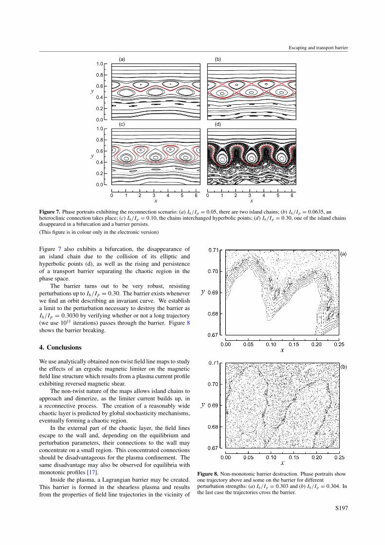
The phase portraits of figure 7 show, for m0 = 3, thescenario of separatrix reconnection [15]: due to the non-monotonicity [12] of our map, there are two island chains withthe same period separated by invariant curves (a); increasingthe perturbation the islands widen and the separatrices merge(b); then the chains interchange their hyperbolic points (c).
S196
Escaping and transport barrier
Figure 7. Phase portraits exhibiting the reconnection scenario: (a) Ih/Ip = 0.05, there are two island chains; (b) Ih/Ip = 0.0635, anheteroclinic connection takes place; (c) Ih/Ip = 0.10, the chains interchanged hyperbolic points; (d) Ih/Ip = 0.30, one of the island chainsdisappeared in a bifurcation and a barrier persists.
(This figure is in colour only in the electronic version)
Figure 7 also exhibits a bifurcation, the disappearance ofan island chain due to the collision of its elliptic andhyperbolic points (d), as well as the rising and persistenceof a transport barrier separating the chaotic region in thephase space.
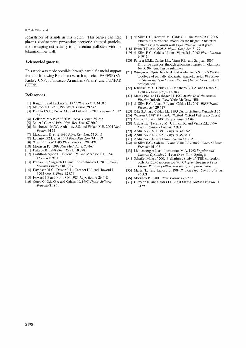
The barrier turns out to be very robust, resistingperturbations up to Ih/Ip = 0.30. The barrier exists wheneverwe find an orbit describing an invariant curve. We establisha limit to the perturbation necessary to destroy the barrier asIh/Ip = 0.3030 by verifying whether or not a long trajectory(we use 1011 iterations) passes through the barrier. Figure 8shows the barrier breaking.
4. Conclusions
We use analytically obtained non-twist field line maps to studythe effects of an ergodic magnetic limiter on the magneticfield line structure which results from a plasma current profileexhibiting reversed magnetic shear.
The non-twist nature of the maps allows island chains toapproach and dimerize, as the limiter current builds up, ina reconnective process. The creation of a reasonably widechaotic layer is predicted by global stochasticity mechanisms,eventually forming a chaotic region.
In the external part of the chaotic layer, the field linesescape to the wall and, depending on the equilibrium andperturbation parameters, their connections to the wall mayconcentrate on a small region. This concentrated connectionsshould be disadvantageous for the plasma confinement. Thesame disadvantage may also be observed for equilibria withmonotonic profiles [17].
Inside the plasma, a Lagrangian barrier may be created.This barrier is formed in the shearless plasma and resultsfrom the properties of field line trajectories in the vicinity of
Figure 8. Non-monotonic barrier destruction. Phase portraits showone trajectory above and some on the barrier for differentperturbation strengths: (a) Ih/Ip = 0.303 and (b) Ih/Ip = 0.304. Inthe last case the trajectories cross the barrier.
S197
E.C. da Silva et al
separatrices of islands in this region. This barrier can helpplasma confinement preventing energetic charged particlesfrom escaping out radially to an eventual collision with thetokamak inner wall.
Acknowledgments
This work was made possible through partial financial supportfrom the following Brazilian research agencies: FAPESP (SaoPaulo), CNPq, Fundacao Araucaria (Parana) and FUNPAR(UFPR).
References
[1] Karger F. and Lackner K. 1977 Phys. Lett. A 61 385[2] McCool S.C. et al 1989 Nucl. Fusion 29 547[3] Portela J.S.E., Viana R.L. and Caldas I.L. 2003 Physica A 317
411[4] Heller M.V.A.P. et al 2005 Czech. J. Phys. 55 265[5] Vallet J.C. et al 1991 Phys. Rev. Lett. 67 2662[6] Jakubowski M.W., Abdullaev S.S. and Finken K.H. 2004 Nucl.
Fusion 44 S1[7] Mazzucato E. et al 1996 Phys. Rev. Lett. 77 3145[8] Levinton F.M. et al 1995 Phys. Rev. Lett. 75 4417[9] Strait E.J. et al 1995 Phys. Rev. Lett. 75 4421
[10] Morrison P.J. 1998 Rev. Mod. Phys. 70 467[11] Balescu R. 1998 Phys. Rev. E 58 3781[12] Castillo-Negrete D., Greene J.M. and Morrison P.J. 1996
Physica D 91 1[13] Petrisor E, Misguich J H and Constantinescu D 2003 Chaos,
Solitons Fractals 18 1085[14] Davidson M.G., Dewar R.L., Gardner H.J. and Howord J.
1995 Aust. J. Phys. 48 871[15] Howard J E and Hohs S M 1984 Phys. Rev. A 29 418[16] Corso G, Oda G A and Caldas I L 1997 Chaos, Solitons
Fractals 8 1891
[17] da Silva E.C., Roberto M., Caldas I.L. and Viana R.L. 2006Effects of the resonant modes on the magnetic footprintpatterns in a tokamak wall Phys. Plasmas 13 at press
[18] Evans T E et al 2005 J. Phys.: Conf. Ser. 7 172[19] da Silva E.C., Caldas I.L. and Viana R.L. 2002 Phys. Plasmas
9 4917[20] Portela J.S.E., Caldas I.L., Viana R.L. and Sanjuan 2006
Diffusive transport through a nontwist barrier in tokamaksInt. J. Bifurcat. Chaos submitted
[21] Wingen A., Spatschek K.H. and Abdullaev S.S. 2005 On thetopology of partially stochastic magnetic fields Workshopon Stochasticity in Fusion Plasmas (Julich, Germany) oralpresentation
[22] Kucinski M.Y., Caldas I.L., Monteiro L.H.A. and Okano V.1990 J. Plasma Phys. 14 303
[23] Morse P.M. and Feshbach H. 1953 Methods of TheoreticalPhysics 2nd edn (New York: McGraw-Hill)
[24] da Silva E.C., Viana R.L. and Caldas I.L. 2001 IEEE Trans.Plasma Sci. 29 617
[25] Oda G.A. and Caldas I.L. 1995 Chaos, Solitons Fractals 5 15[26] Wesson J. 1987 Tokamaks (Oxford: Oxford University Press)[27] Caldas I.L. et al 2002 Braz. J. Phys. 32 980[28] Caldas I.L., Pereira J.M., Ullmann K. and Viana R.L. 1996
Chaos, Solitons Fractals 7 991[29] Abdullaev S.S. 1999 J. Phys. A 32 2745[30] Abdullaev S.S. 2002 J. Phys. A 35 2811[31] Abdullaev S.S. 2004 Nucl. Fusion 44 S12[32] da Silva E.C., Caldas I.L. and Viana R.L. 2002 Chaos, Solitons
Fractals 14 403[33] Lichtenberg A.J. and Lieberman M.A. 1992 Regular and
Chaotic Dynamics 2nd edn (New York: Springer)[34] Schaffer M. et al 2005 Preliminary study of ITER correction
coils for ELM suppression Workshop on Stochasticity inFusion Plasmas (Julich, Germany) oral presentation
[35] Martin T.J. and Taylor J.B. 1984 Plasma Phys. Control Fusion26 321
[36] Morrison P.J. 2000 Phys. Plasmas 7 2279[37] Ullmann K. and Caldas I.L. 2000 Chaos, Solitons Fractals 11
2129
S198