Embed Size (px)
Citation preview
1. (b)2. (b)3. (c)4. (b)5. (a)6. (a)7. (b)8. (d)9. (d)10. (d)11. (a)12. (c)13. (a)14. (a)15. (b)16. (c)17. (a)18. (b)19. (c)20. (a)21. (d)22. (a)23. (b)24. (c)25. (d)26. (c)27. (c)28. (b)29. (b)30. (a)31. (b)32. (d)33. (b)
34. (c)35. (a)36. (b)37. (b)38. (b)39. (b)40. (b)41. (b)42. (d)43. (c)44. (c)45. (a)46. (d)47. (a)48. (b)49. (b)50. (d)51. (c)52. (c)53. (c)54. (b)55. (d)56. (d)57. (a)58. (b)59. (a)60. (b)61. (d)62. (c)63. (b)64. (b)65. (a)66. (a)
67. (d)68. (c)69. (a)70. (c)71. (a)72. (a)73. (d)74. (b)75. (b)76. (a)77. (c)78. (a)79. (a)80. (d)81. (b)82. (b)83. (b)84. (a)85. (c)86. (a)87. (d)88. (a)89. (b)90. (b)91. (d)92. (d)93. (c)94. (b)95. (b)96. (a)97. (a)98. (d)99. (c)
100. (c)101. (b)102. (a)103. (a)104. (b)105. (b)106. (c)107. (a)108. (b)109. (c)110. (b)111. (b)112. (b)113. (b)114. (d)115. (c)116. (b)117. (c)118. (d)119. (d)120. (c)121. (c)122. (c)123. (a)124. (d)125. (a)126. (d)127. (d)128. (b)129. (b)130. (c)131. (b)132. (a)
133. (b)134. (c)135. (b)136. (a)137. (d)138. (d)139. (c)140. (a)141. (b)142. (c)143. (a)144. (a)145. (c)146. (a)147. (c)148. (a)149. (b)150. (a)151. (a)152. (d)153. (c)154. (c)155. (a)156. (a)157. (a)158. (d)159. (d)160. (b)
ESE-2017 PRELIMS TEST SERIESDate: 1th January, 2017
ANSWERS
IES M
ASTER
(2) (Test-20 FL-3) 1st January 2017
8010009955, 9711853908 [email protected], [email protected]. : E-mail:
Regd. office : Phone : F-126, (Upper Basement), Katwaria Sarai, New Delhi-110016 011-41013406
1. (b) Burls or excrescence are formed when treereceives injury in its young age.
2. (b) Ammonium chloride is hydrating agentwhile others are dehydrating agents.
3. (c) In belt conveyer, tendency to segregateconcrete is more.
4. (b) Water cement ratio = Weight of free waterWeight of cement
5. (a)
6. (a) Blown bitumen is obtained by passing airunder pressure at higher temperature.Such bitumen can be used as roofing anddamp-proofing felts, in manufacture of pipeasphalts and joints fillers, and as heatinsulating material.
7. (b)
fwd = wp p wk
mw mw
f k fy y
= wkwk
0.85 f 0.567f1.5
8. (d) Terrazzo is artificial stone.
Terrazzo is used for bathrooms, residentialbuildings, temples, etc.
9. (d) Aluminium is an excellent reflector ofelectro magnetic and sound waves. Dueto high corrosion resistance of aluminum,the maintenace cost is negligible.
10. (d)
11. (a)
12. (c) PI Consistency
O Non-plastic
< 7 Low-plastic
7-17 Medium plastic
> 17 High plastic
13. (a)1K
decreases with increase in temperture
K increases with increase in temperature.
14. (a) Under the point load, the vertical stress isgiven by
= 20.4775Q
Z(from Bossinesq’s equation
2
0.4775Q 0.254z
15. (b)
i = Q 0.06 0.6A 0.002 50
at middle = (19.13 – 9.81) × 0.06 – 0.06× 0.6 × 9.81
0.206 0.21 kN/m2
16. (c)
Sn =C
CH F
0.116 =20
2.5 20 H
H =1
2.5 0.116 = 3.448 m
17. (a)
18. (b) sin = 1 3
1 3
( ) / 2( ) / 2
sin = 1
1
100100
1 1100 2 200
21 300KN / m
2d 300 100 200KN / m
19. (c) The width of test pit is kept 5 times thewidth of the plate.
20. (a) Flow duration curve of a stream is a plotof discharge against percentage of timethe flow was equalled or exceeded.A flow duration curve based on daily flowdata will be steeper than a curve basedon monthly flow data because the largerinterval data will smoothen out thevariations in shorter interval data.
21. (d) Under-reamed pile is a special type ofbored pile which is provided with a bulb/pedestal at the end. The usual size of suchpiles are 150 to 200 mm shaft diameter,3 to 4m long. Its bulb diameter is 2 to 3times the shaft diameter.
IES M
ASTER
(Test-20 FL-3) 1st January 2017 (3)
8010009955, 9711853908 [email protected], [email protected]. : E-mail:
Regd. office : Phone : F-126, (Upper Basement), Katwaria Sarai, New Delhi-110016 011-41013406
22. (a) The rails are to be connected at their ends.This is achieved by means of a pair offish plates per tail. The holes are drilledthrough the plates and the web of railsand then the fish bolts and nuts areprovided in these holes. when the boltsand nuts are tightened up, the rails arejoined together and a continuous track isformed.
23. (b)
24. (c)
25. (d) Excavation of small sized heading (drift)is done centrally at top or bottom of the facein the drift method. In heading and benchingmethod the top portion is driven in advance ofthe bottom portion.
In full face method the whole section isexcavated once for all. It is suitable for tunnelsof small cross-sections area say upto 3mdiameter.
26. (c)
27. (c)
28. (b) Astigmation is optical lens defect whileaplanation, definition and acromatism isdesirable optical characterstics.
29. (b)
30. (a)
31. (b)
32. (d)
33. (b) The beam is designed as a balancesection.
So, N.A 0.48 d
= 0.48 × 450 = 216 mm
Df = 100 mm
f7 D3 =
7 1003
= 233.33 mm > 216 mm
So the flange depth will be stressed withboth rectangular and parabolic portion ofstress block.
So modified Df = yf
= 0.15 x4 + 0.65 DF
= 0.15×216 + 0.65×100
= 97.4 mm
34. (c) The modification factor to ld ratio
decrease with increase in tensilereinforcement and grade of steel.
The permissible ld ratio is decrease and
it is a indicator of increased deflection.
Higher grade and higher tensilereinforcement are indicator of higherstresses and higher loads which giveshigher deflection.
35. (a) Minimum bar dia for Fe415 in slab = 8mm
Maximum dia = D8
= 150
8 = 18.75
So, Minimum is 8 mm
and Maximum is 18 mm
36. (b) In two way slab.
Middle strip = l0.75
Edge strip = l0.125
0.125 lx
0.75 lx
0.75 ly0.125 ly
ly
lx
Middle strip in shorter direction= 0.75 ly= 0.75 × 6= 4.5 m
Edge strip in longer direction= 0.125 lx= 0.125 × 4= 0.5 m
37. (b) upward force by tendon atcentre 2Psin 2P tan
upward force due to prestress
downward load=
0 152 P3.
IES M
ASTER
(4) (Test-20 FL-3) 1st January 2017
8010009955, 9711853908 [email protected], [email protected]. : E-mail:
Regd. office : Phone : F-126, (Upper Basement), Katwaria Sarai, New Delhi-110016 011-41013406
For balancing, 0 152 P w 90KN
3.
3 1P 90
0 15 2.
P 900KN
38. (b) In WSM failure occurs when materialreaches it’s permissible stress. So failureis stress controlled. In LSM failure occurswhen material reaches its limiting valueof strain. So failure is strain controlled.
39. (b) A given x section (balance) with givengrade of concrete and steel will give largerMOR in LSM due to larger area of steel inbalance section in LSM.
40. (b) to check the servicebility criteria
Combination (i)
= 1 × (DL + LL)
= 1 × (5 + 10) = 15 kN/m
Combination (ii)
= 1 D.L 0.8 L.L. E.L
= 5 0.8 10 10
= 21 kN/m
So design load will be 21 kN/m
41. (b)
42. (d) D = i sC C 1100 100 2005 5
B2 = 1100 – 2 × 200 = 700 Rs
B3 = 1100 – 3 × 200 = 500 Rs
B2 + B3 = 1200 Rs.
43. (c) Hindered settling occurs in secondarysedimentation tank of the activated sludgeprocess.
44. (c) The steps involved in vermi compostingare:
1. Dig a small pit.2. Line the pit with straw or dried leaves
and grass.3. Organise the disposal of organic
domestic waste into the pit as and whengenerated.
4. Introduce a culture of worm that is nowproduced commercially.
5. Cover the pit contents daily, bysprinkling of dried leaves and soil everyday.
6. Water the pit once or twice a week tokeep it moisture.
7. Turn over the content of pit every 15days.
45. (a) Some time seeded water is used fordilution in BOD test. The seeded waterwith seeding of mixed bacterial culture isused, but it not used to decomposedifferent types of organic matter. Seededwater is used when there is difficiency ofbacteria in the sample, then we introducebacteria from out sides.
46. (d)
(1) The rate is more in shallow depth(2) Rate is more in a running stream than in
a quiscent pond(3) More is the saturation deficit, more is the
rate of oxygen supplied(4) More is temperature, more is the rate
47. (a)
(1) the flow of waste water in sewer issteady and uniform as per assumptionand the unsteadiness and non-uniformityof flow characterstics are accounted forin the design by proper sizing ofmanholes.
(2) Design of sewers is based on peak flowdischarge i.e. maximum hourlydischarge.
48. (b) Particles with velocity above or equal toSOR will be completely removed andthose with settling velocity below SOR are
removed in proportional, VSOR
where V is
the settling velocity.Thus overall removal =
(0.5 100 0.1 100 0.05 100)1001
= 165 mg/L
IES M
ASTER
(Test-20 FL-3) 1st January 2017 (5)
8010009955, 9711853908 [email protected], [email protected]. : E-mail:
Regd. office : Phone : F-126, (Upper Basement), Katwaria Sarai, New Delhi-110016 011-41013406
49. (b) Volume of sample pollutant = 0.5 ml
Volume of diluted pollutant = 100 ml
Dilution ratio = 1000.5 = 200
Consumption of oxygen = 2 mg/l BOD5 = Consumption of oxygen × Dilution
factor= 2 × 200 = 400 mg/l
50. (d) Recirculation factor
F =
21 R
(1 0.1R)
F =
21 1.5 1.89
(1 0.15)
=
1
100w1 0.0044
V FW1 =2000 × 1000 × 1.50 × 10–6 kg/dayW1 = 300 kg/dayV1 = 2000 m3 = 0.2 hactare-m
=
1003001 0.0044
0.2 1.89 = 88.97 89%
51. (c) Suspended particulate matter causesproblem in respiration. Carbon monoxidecombine with haemoglobin of blood to formcarboxyhaemoglobin which reduces theoxygen carrying capacity of the blood.SO2 causes discolouration, leaching ofbuilding materials. NO, a principlecomponent of acid rain affects vegetation.
52. (c)
53. (c) Equating head to efficients
1 1
1
N DH =
2 2
2
N DH
2D = 16 40025
= 320 mm
54. (b) 2 = 2D N60
=3.14 0.1 3000
60
= 15.7 m/s
For radial vane tips w2V = 2u
= 15.7 m/s
H =w2 2
gHV u
and
w2 2
gHV u = 0.8
H =220.8 u
9.81
= 20.8 15.79.81
= 20.10 m
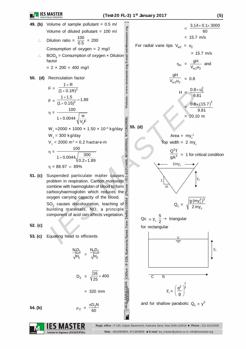
55. (d)
Area = myc2
Top width = 2 myc
2
3Q TgA = 1 for critical condition
1m
yc
2myc
QC =2 3c
c
g (my )2 my
Qc yc 52
triangular
for rectangular
yc
C B
yc
12 3q
g
and for shallow parabolic 2cQ y
IES M
ASTER
(6) (Test-20 FL-3) 1st January 2017
8010009955, 9711853908 [email protected], [email protected]. : E-mail:
Regd. office : Phone : F-126, (Upper Basement), Katwaria Sarai, New Delhi-110016 011-41013406
56. (d)
57. (a) For given specific energy the discharge ismaximum when flow is in critical state
Thus depth of flow Y = Yc
Y = Yc
= 2 2E 1.8 1.2 m3 3
For rectangular channel –
Yc = 1
2 3qg
1.2 =1
2 3qg
q =1
3 2(1.2) 9.81 q = 4.12 m3/s per m
Total discharge,
3mQ 4.12 5 20.6 s
58. (b)Vertical component weight of liquidover the curved surface
= 2
w w w12 4 4 (8 )
4
Horizontal component force on verticalprojection of the curved surface
wh A
= w w w2 0.5 1 4 2.5 4 10
So, ratio = 810
59. (a)By equating the pressure in inclinedtube and container at the level ofinterface of oil and mercury.
P + h × 0.8 w = wsin 13.6 l
P = w w10.2 13.6 0.05 0.82
P = (1.36 – 0.04) w = 1.32 w
= 1.32 m of water
oil
P =
1.320.8 = 1.65m
So pressure = 1.65m of liquid
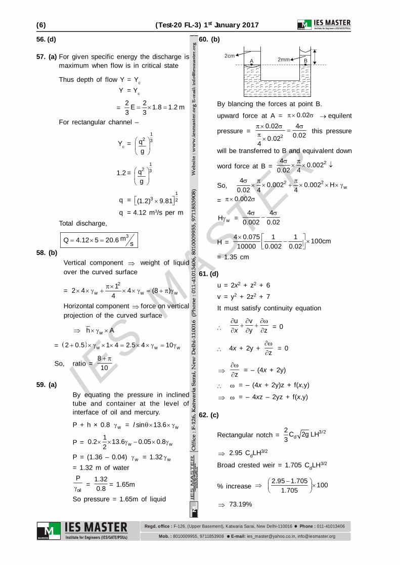
60. (b)
2mm2cm
A B
By blancing the forces at point B.
upward force at A = 0.02 equilent
pressure = 2
0.02 40.020.02
4
this pressure
will be transferred to B and equivalent down
word force at B = 24 0.0020.02 4
So, 2 2w
4 0.002 0.002 H0.02 4 4
= 0.002
wH = 4 4
0.002 0.02
H =
4 0.075 1 1 100cm10000 0.002 0.02
= 1.35 cm
61. (d)u = 2x2 + z2 + 6v = y2 + 2z2 + 7It must satisfy continuity equation
u v
y z
x = 0
4x + 2y + z
= 0
z
= – (4x + 2y)
= – (4x + 2y)z + f(x,y)
= – 4xz – 2yz + f(x,y)
62. (c)
Rectangular notch = 3/2d
2 C 2g LH3
2.95 CdLH3/2
Broad crested weir = 1.705 CdLH3/2
% increase
2.95 1.705 100
1.705
73.19%
IES M
ASTER
(Test-20 FL-3) 1st January 2017 (7)
8010009955, 9711853908 [email protected], [email protected]. : E-mail:
Regd. office : Phone : F-126, (Upper Basement), Katwaria Sarai, New Delhi-110016 011-41013406
63. (b)Assuming the flow in pipe is laminar.
RU
r
0 =
R P2 x
=
3 350 10 50 102 10
=250
2 N/m2
= 0.125 kPa
64. (b)
Oil
water
Since the interface is shown clearly i.e.no intermixing. The stress at interface mustbe same from both sides i.e. oil and waterside.
oil = water
00
dudy
= ww
dudy
0 w
du dudy dy
= w
0
The shear stresses from both sides aresame so it should be continuous andvelocity is discontinuous as shown abovei.e. velocity gradient are in reverse ratioof their viscosity i.e. different.
65. (a) Weber Model is used for Flow over weirs involving very low heads
Very thin sheet of liquid flowing over asurface
Capillary waves in channels, etc.Mach Model is used in Aerodynamic testing
In phenomena involving velocitiesexceeding the speed of sound.
Hydraulic model testing for the cases ofunsteady flow, especially water hammerproblems.
Froude Model is used in Free surface flows such as flow over
spillways, sluices, etc Flow of jet from an orifice or nozzle Problems in which waves are likely to
be formed on the surface. Problems in which fluids of different
mass densities flow over one another.66. (a) Porosity of soil can’t exceed 100% as
VV V and VV / V
Water content of fine grain soil is generallymore than coarse grained soils. Specificgravity of coarse grained soil is generallyless than that of fine grained soil. Sandbath method is f ield method fordetermination of water content.
67. (d) Momentum equation is not used in Hardy-cross method.
68. (c)
LReservoir
A B
Pressure distribution at B.
time
2LC
2LC
2LC
2LC
O
+ph
–ph
T0 =2LC
=2 2000
1000
= 4 sec.Thus, negative water hammer pressure at
the valve will last for 4 – 8 sec.
69. (a) Similar to splices in flanges, webs alsomay need splicing or cuts outs maybecome necessary in webs for routing ofservices. Such web splices and cut outsare best provided at locations away fromhigh shear and large concentrated loads.
IES M
ASTER
(8) (Test-20 FL-3) 1st January 2017
8010009955, 9711853908 [email protected], [email protected]. : E-mail:
Regd. office : Phone : F-126, (Upper Basement), Katwaria Sarai, New Delhi-110016 011-41013406
Splices in web are designed to withstandthe shear and moments at the splicedsection.
70. (c) The length of weld connecting each edgeof the batten plate to the member shall, inaggregate, be not less than half the depthof the batten plate. At least one-third ofthe weld shall be placed at each end ofthe edge. In addition, the welding shall bereturned along the the other two edges ofthe plates transeversely to the axis of mainmember for a length not less than theminimum lap specified:
71. (a) Gross diameter of rivet = 20 + 1.5= 21.5 mm
Strength of rivet in bearing = b × d × t= 300 × 21.5 × 16 = 103.20 kNStrength of rivet in double shear
=
22 d4
=
22 100 21.54
= 72.61 kN
Strength of plate per pitch
= at (P – d) t
= 150 × (90 – 21.5) × 16 = 164.40 kN Strength of joint per pitch = Minimum of
above three value = 72.610 kNStrength of plate per pitch = 150 × 90 ×16 = 216 kN
Efficiency = 72.61 100216
= 33.61%
72.(a)
73. (d) In most cases of the connections subjectedto tension forces, the flexibility of theconnected parts can lead to deformationsthat increases the tension applied to thebolts. The additional tension is calledprying force.
74. (b)
C
B
A 125 mm leg
75 mm leg
55
79
50 50 50dhole = 22
Path AC
Net area
= 1164 – 2 × 22 × 6 = 900 mm2
Path ABC
=
2 250 501164 3 22 6 64 55 4 79
= 883.65 mm2
75. (b)
76. (a)Assume te = 24 hActual rainfall = (1.6 + 5.4 + 4.1)
= 11.1 cmRunoff = 4.7 cm
Loss = 6.4 cm
trial = 6.43 8 = 0.267 cm/h
Loss in first 8h = 8 × 0.267= 2.133 cm > actual rainfall of 1.6 cm/hHence te < 24 h2nd trial : Let te = 16 hInfiltration loss in remaining 16 h
= 6.4 – 1.6 = 4.8 cm
=4.8 0.3cm / h16
Losses in 2nd and 3rd time block = 2.4 cmwhich is less than actual rainfall values.
Hence = 0.3 cm/h
77. (c) The plastic hinges are formed first at thesections subjected to the greatestdeformation (curvature).
78. (a)(1) The contractor whose tender has been
accepted is to deposite 10% of the tenderestamount as security money with thedepartment inclusive of the earnest moneyalready deposited.
(2) This amount is kept as a check so that thecontractor fulfils all the terms and conditionand caries out due work satisfactory with ina time limit. The security money also servesas a security against the materials or duetools and machineries provided by thedepartment.
IES M
ASTER
(Test-20 FL-3) 1st January 2017 (9)
8010009955, 9711853908 [email protected], [email protected]. : E-mail:
Regd. office : Phone : F-126, (Upper Basement), Katwaria Sarai, New Delhi-110016 011-41013406
(3) The security money is refunded to thecontractor after satisfactorily working of theproject upto 6 months or one rainy season.
79. (a) Multiplying constant
K = fi
K = 24012
K = 20
80. (d) Item rate contract is also known as unitprice contract or schedule contract. Acontractor takes work on the basis of itemrate basis. He is required to quote rate forindividual item of work on the basis of billof quantities furnished by the department.The amount received by contractorsdepends upon the quantities of workactually performed. The payment to thecontractor is made on the basis of thedetailed measurement of different itemsof work actually executed.
81. (b)
82. (b)Free float FF = Total float – Sj
= (48 – 12) – (48 – 36)= 22 – 12= 10
83. (b)
84. (a) Power shovel is used in excavation ofearth is confined area or pit.Hoe is used in excavation of trenchesbecause trenches need precise control ofdimensions and hoe is suitable for thispurpose.
Clamshell is used in rehauling of loose orexcavated material.
Bull dozers are used in clearing andscrubbing worksite.
85. (c) When the size of the bucket is to bechanged the length of the boom also needsto be changed as the maximum liftingcapacity is limited by the force that willcause the tilting of the machine.
The weight of the bucket + the load it cancarry is called the capacity of the dragline.
A large boom will be required toincrease the reach of the draglien butin order to keep the tilting torqueconstant the size of bucket must bereduced.
86. (a)
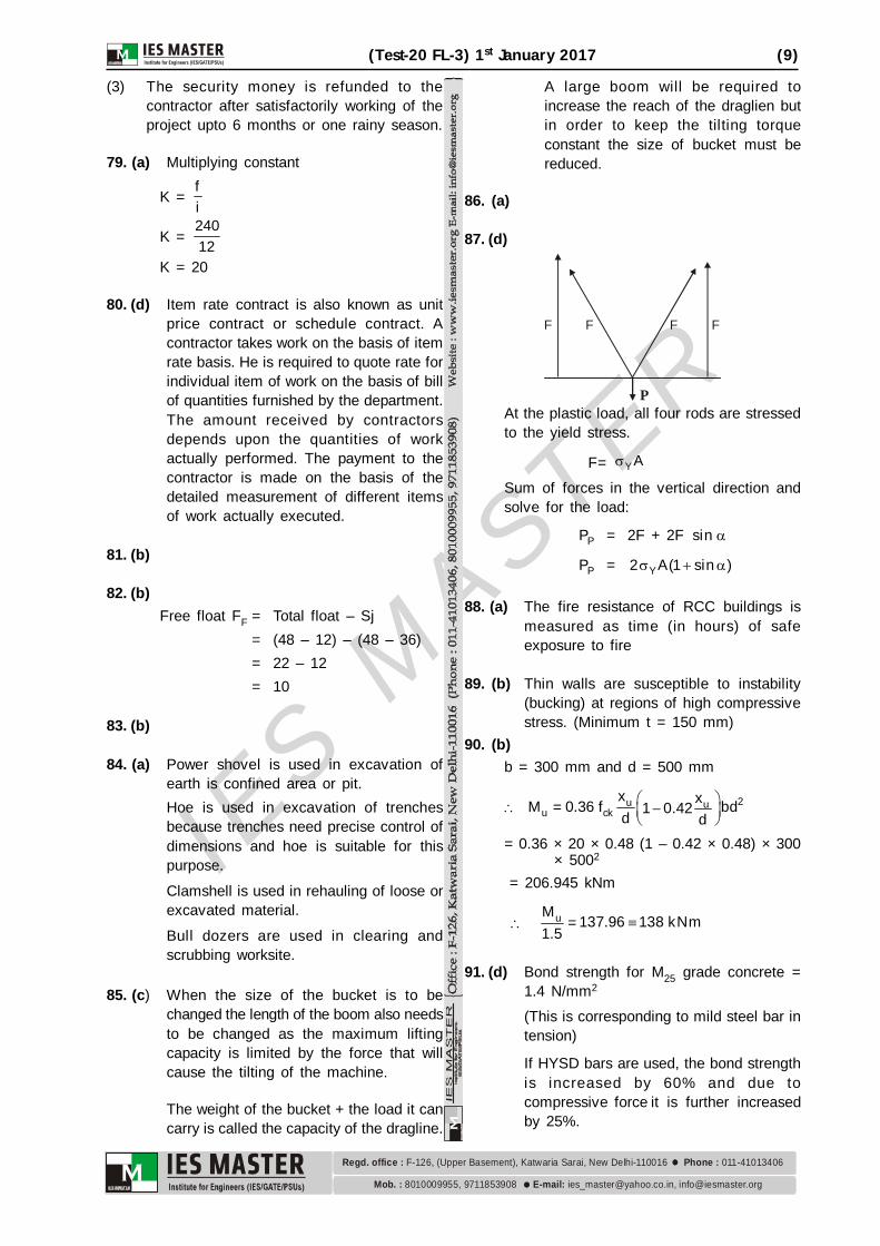
87. (d)
P
F FF F
At the plastic load, all four rods are stressedto the yield stress.
F= YA
Sum of forces in the vertical direction andsolve for the load:
PP = 2F + 2F sin
PP = Y2 A(1 sin )
88. (a) The fire resistance of RCC buildings ismeasured as time (in hours) of safeexposure to fire
89. (b) Thin walls are susceptible to instability(bucking) at regions of high compressivestress. (Minimum t = 150 mm)
90. (b)b = 300 mm and d = 500 mm
2u uu ck
x xM 0.36 f bd= 1 0.42d d
= 0.36 × 20 × 0.48 (1 – 0.42 × 0.48) × 300 × 5002
= 206.945 kNm
uM 137.96 138 kNm=1.5
91. (d) Bond strength for M25 grade concrete =1.4 N/mm2
(This is corresponding to mild steel bar intension)
If HYSD bars are used, the bond strengthis increased by 60% and due tocompressive force it is further increasedby 25%.
IES M
ASTER
(10) (Test-20 FL-3) 1st January 2017
8010009955, 9711853908 [email protected], [email protected]. : E-mail:
Regd. office : Phone : F-126, (Upper Basement), Katwaria Sarai, New Delhi-110016 011-41013406
Modified bond strength bd = 1.6 × 1.25 ×1.40 N/m2
bd = 2.8 N/mm2
Minimum development length required
Ld = y
bd
0.87f4
Ld = 0.87 415 12
4 2.8
Ld 386.8
dL 390 mm
92. (d) Shear resistance of shear reinforcement,
Vus = 0 87 y sv
v
. f A dS
= 20 87 415 2 8 350
4 200.
= 63.52 kN
Shear resistance of concrete,Vuc = cbd
= 0.5 × 200 × 350 = 35 kN Total shear capacity = Vus + Vuc
= 63.52 + 35= 98.52 kN
93. (c) If no tension occur in the column section,maximum compressive strain at highlycompressed extreme fiber in the concretesubjected to axial compression andbending will be
= 0.0035 – 0.75 × Strain in leastcompression fiber
CH = 0.0035 – 0.75 × CL
A B
DC
CH
CH = 0.0035 – 0.75 × 0
CH 0.0035
94. (b)H = 200 m Head of water
P = gH
= 3 6 210 9.81 200 1.962 10 N m
= 21.962N mm 1.962MPa
h =Pd2t
20 = 1.962 1000
2t t = 49.05 mm
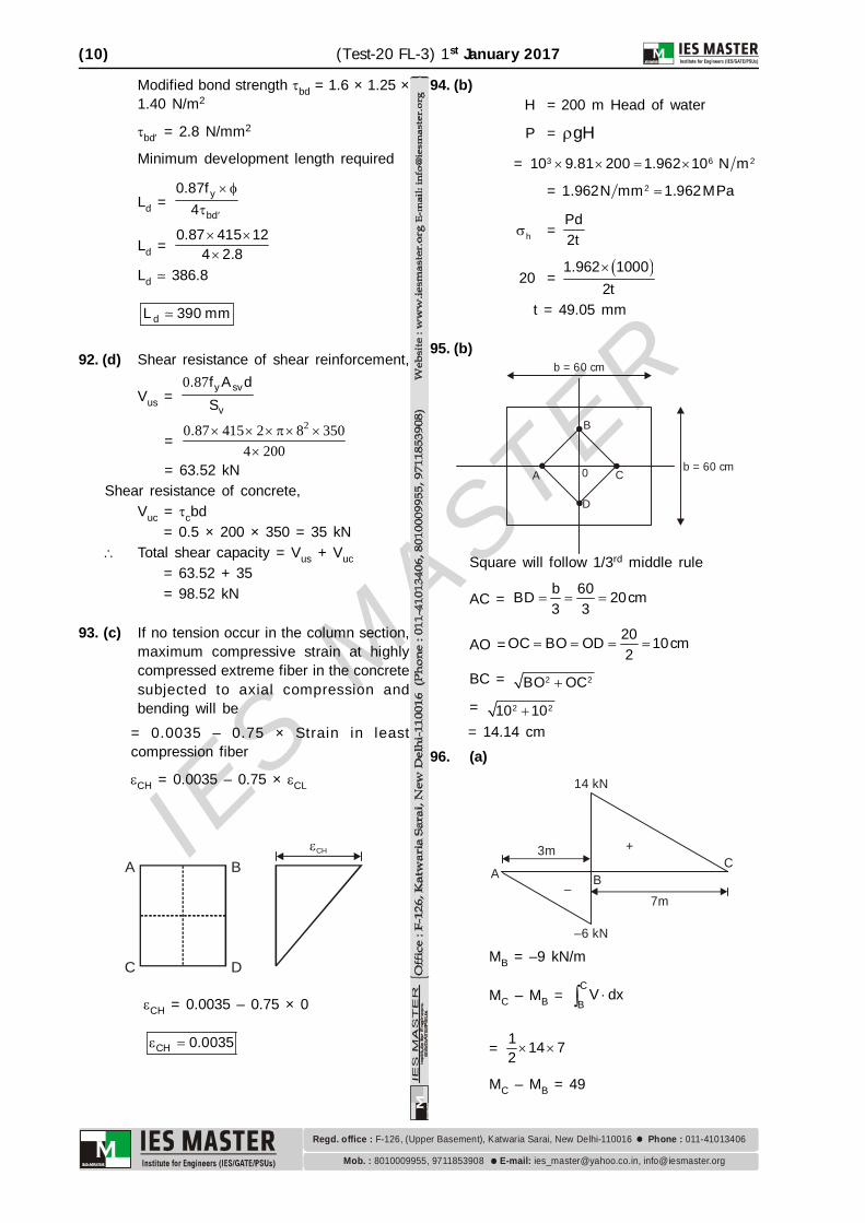
95. (b)b = 60 cm
A
B
C
D
b = 60 cm0
Square will follow 1/3rd middle rule
AC = b 60BD 20cm3 3
AO = 20OC BO OD 10cm2
BC = 2 2BO OC= 2 210 10
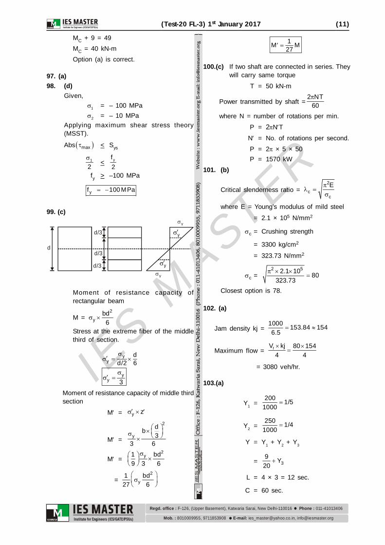
= 14.14 cm96. (a)
3m
7m
CBA
–6 kN
14 kN
+
–
MB = –9 kN/m
MC – MB = C
BV dx
= 1 14 72
MC – MB = 49
IES M
ASTER
(Test-20 FL-3) 1st January 2017 (11)
8010009955, 9711853908 [email protected], [email protected]. : E-mail:
Regd. office : Phone : F-126, (Upper Basement), Katwaria Sarai, New Delhi-110016 011-41013406
MC + 9 = 49MC = 40 kN-mOption (a) is correct.
97. (a)98. (d)
Given,
1 = – 100 MPa
2 = – 10 MPaApplying maximum shear stress theory(MSST).
Abs max < Sys
1
2
< yf2
fy > –100 MPa
yf 100 MPa
99. (c)
d
d/3
d/3
d/3
y
y
y
y
Moment of resistance capacity ofrectangular beam
M = 2
ybd6
Stress at the extreme fiber of the middlethird of section.
yy
dd/2 6
yy 3
Moment of resistance capacity of middle thirdsection
M = y z
M =
2
y
db3
3 6
M =2
y1 bd9 3 6
= 2
y1 bd27 6
1M M27
100.(c) If two shaft are connected in series. Theywill carry same torque
T = 50 kN-m
Power transmitted by shaft =2 NT
60
where N = number of rotations per min.P = 2NT
N = No. of rotations per second.P = 2 × 5 × 50P = 1570 kW
101. (b)
Critical slenderness ratio = 2
cc
E
where E = Young’s modulus of mild steel
= 2.1 × 10⁵ N/mm2
c = Crushing strength
= 3300 kg/cm2
= 323.73 N/mm2
c =2 52.1 10 80
323.73
Closest option is 78.
102. (a)
Jam density kj = 1000 153.84 1546.5
Maximum flow =
fV kj 80 1544 4
= 3080 veh/hr.
103.(a)
Y1 =200 1/5
1000
Y2 =250 1/4
1000
Y = Y1 + Y2 + Y3
= 39 Y20
L = 4 × 3 = 12 sec.
C = 60 sec.
IES M
ASTER
(12) (Test-20 FL-3) 1st January 2017
8010009955, 9711853908 [email protected], [email protected]. : E-mail:
Regd. office : Phone : F-126, (Upper Basement), Katwaria Sarai, New Delhi-110016 011-41013406
C =
3
1.5L 5 1.5 12 51– Y 1 9/20 Y
Y3 = 1/6
If green time for 3rd phase
=
1/ 660 – 12 12.97 13sec.1 1 15 4 6
104.(b)105. (b)106. (c)
2S 80 80R 80 m8M 8 10
107. (a)108. (b)
Volume of sewage treated = 4.5 M-l/day
Since suspended solids amount to 275 mg/l,we have the mass of suspended solidspresent in sewage.
= 66
275 4.5 1010
= 1237.5 Kg/day
Since 50% of sol ids are removed insedimentation tank we have, the mass ofsolids removed in sedimentation tank
= 501237.5
100 = 618.75 Kg/day
When moisture content of sludge is 98% then2 kg of solids (dry sludge) will make = 100kg of wet sludge
618.65 kg of solids (dry sludge) will make
= 100 618.75
2
= 30940 Kg= 30.94 tones
109. (c)
De chlorinating agentSodium thiosulphateActivated carbonSulphur dioxide
Fluoridation agentSodium silica fluoride
Hydro silicic acidSodium fluoride
110.(b)
111. (b) Only if sodium alkalinity is absent thenonly we can say that the entire alkalinityis due to presence carbonates andbycarbonates of calcium and Magnesium.In this case only we can say that carbonatehardness is equal to the alkalinity.
112.(b)113. (b) Re = 0.05
laminar flow
So Cd = 24Re
Cd = 24
0.05Cd = 480
114. (d)
Vw = C – V1
Vw = Absolute velocity of surge = ?y1 = 1.6 m, V1 = 2.4 m/s
C = gy
= 10 1.6
C = 4Vw = 4 – 2.4 = 1.6 m/s.
115. (c) 525R 0.90 0.91580
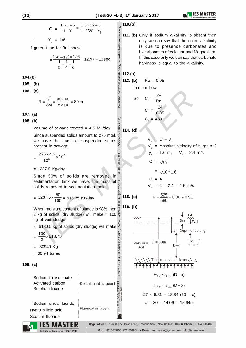
116. (b)
x = Depth of cutting
D–x
GL3m
A
Level of cutting
D = 30m
Thin Impervious layer
Previous Soil
W.T
w satH (D x)
w satH (D x)
27 × 9.81 = 18.84 (30 – x)
x = 30 – 14.06 = 15.94m
IES M
ASTER
(Test-20 FL-3) 1st January 2017 (13)
8010009955, 9711853908 [email protected], [email protected]. : E-mail:
Regd. office : Phone : F-126, (Upper Basement), Katwaria Sarai, New Delhi-110016 011-41013406
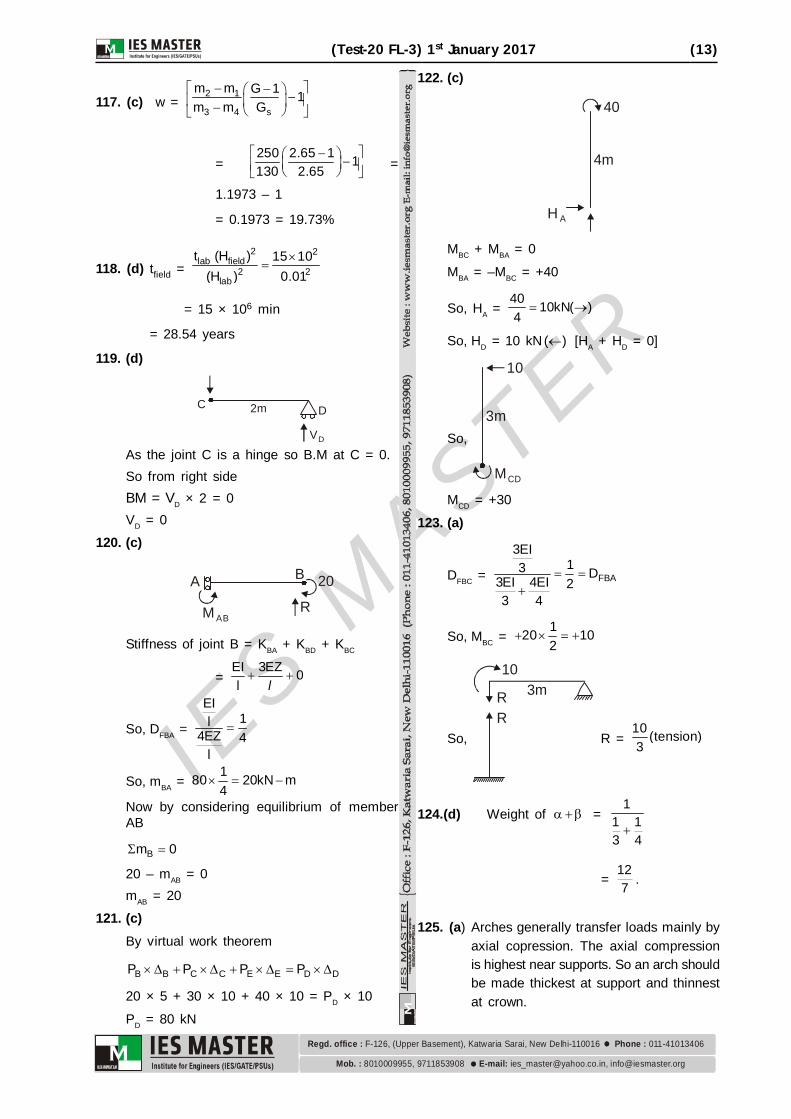
117. (c) w = 2 1
3 4 s
m m G 1 1m m G
= 250 2.65 1 1130 2.65
=
1.1973 – 1
= 0.1973 = 19.73%
118. (d) tfield =
2 2
lab field2 2
lab
t (H ) 15 10(H ) 0.01
= 15 × 106 min
= 28.54 years
119. (d)
C D
VD
2m
As the joint C is a hinge so B.M at C = 0.So from right sideBM = VD × 2 = 0VD = 0
120. (c)
A B
MABR
20
Stiffness of joint B = KBA + KBD + KBC
= EI 3EZ 0l
l
So, DFBA =
EI1l
4EZ 4l
So, mBA = 180 20kN m4
Now by considering equilibrium of memberAB
Bm 0
20 – mAB = 0mAB = 20
121. (c)By virtual work theorem
B B C C E E D DP P P P
20 × 5 + 30 × 10 + 40 × 10 = PD × 10
PD = 80 kN
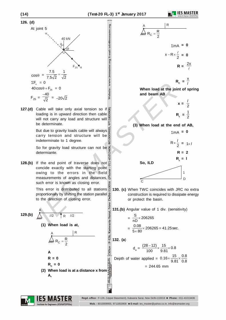
122. (c)
40
4m
HA
MBC + MBA = 0
MBA = –MBC = +40
So, HA = 40 10kN( )4
So, HD = 10 kN( ) [HA + HD = 0]
So,
10
3m
MCD
MCD = +30
123. (a)
DFBC = FBA
3EI13 D3EI 4EI 2
3 4
So, MBC = 120 102
So,
103mR
R R =
10 (tension)3
124.(d) Weight of =1
1 13 4
= 127 .
125. (a) Arches generally transfer loads mainly byaxial copression. The axial compressionis highest near supports. So an arch shouldbe made thickest at support and thinnestat crown.
IES M
ASTER
(14) (Test-20 FL-3) 1st January 2017
8010009955, 9711853908 [email protected], [email protected]. : E-mail:
Regd. office : Phone : F-126, (Upper Basement), Katwaria Sarai, New Delhi-110016 011-41013406
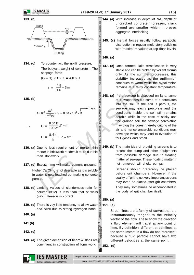
126. (d)At joint 5
F25
40 kN
cos = 7.5 1
7.5 2 2
F = 0
2540cos F = 0
F25 = 402
= 20 2
127.(d) Cable will take only axial tension so ifloading is in upward direction then cablewill not carry any load and structure willbe determinate.
But due to gravity loads cable will alwayscarry tension and structure wil l beindeterminate to 1 degree.
So for gravity load structure can not bedetermiante.
128.(b) If the end point of traverse does notconcide exactly with the starting pointowing to the errors in the f ieldmeasurements of angles and distances,such error is known as closing error.This error is distributed to all stationsproportionally by shifting the station parallelto the direction of closing error.
129.(b) l/2 l/2R
A
(1) When load is at,
RA
CRR2
AR = 0RC = 0
(2) When load is at a distance x fromA,
RA
CRR2
mA = 0
x R2
= 0
R = 2x
RC =xl
When load at the joint of springand beam AB
x = 2l
Rc = 12
(3) When load at the end of AB,
mA = 0
R2
l = 1 l
R = 2Rc = l
So, ILD
1
CD
130. (c) When TWC coincides with JRC no extraconstruction is required to dissipate energyor protect the basin.
131.(b) Angular value of 1 div. (sensitivity)
= S 206265
nD
= 0.08 206265 41.25sec.=
5 80
132. (a)
dw = (28 12) 15 0.8
100 9.81
Depth of water applied = 15 0.80.16
9.81 0.8
= 244.65 mm
IES M
ASTER
(Test-20 FL-3) 1st January 2017 (15)
8010009955, 9711853908 [email protected], [email protected]. : E-mail:
Regd. office : Phone : F-126, (Upper Basement), Katwaria Sarai, New Delhi-110016 011-41013406
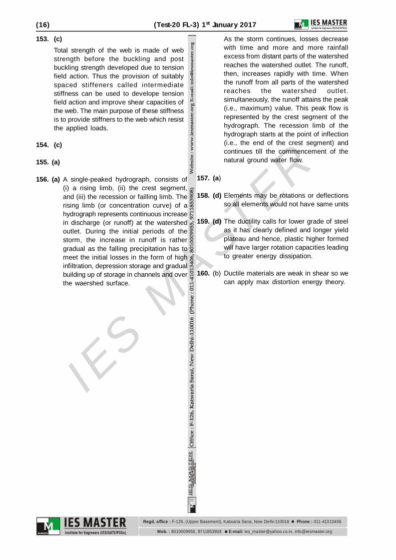
133. (b)
Cutting
"Berm"
Bank
134. (c) To counter act the uplift pressure,The buoyant weight of concrete = Theseepage force(G – 1) × t × 1 = 4.8 × 1
t =4.8 3 m1.6
135. (b)
2
6 43
mD 10 8.64 10 Bm /s
days
D = 8.64 B m100
D = 8.64
cm
136. (a) Due to less requirement of mortor, thinmortor in brickwork renders it more durablethan stonework.
137. (d) Excess lime will make cement unsound.
Higher Ca(OH)2 is not desirable as it is solublein water & gets leached out making concreteporous.
138. (d) Limiting values of slenderness ratio forcolumn (=12) is less than that of walls(=27). Reason is correct.
139. (c) There is vey little tendency to allow waterand swell due to strong hydrogen bond.
140. (a)
141.(b)
142. (c)
143. (a) The given dimension of beam & slabs areconvinient in construction of form work.
144. (a) With increase in depth of NA, depth ofuncracked concrete increases, crackformed are smaller which improvesaggregate interlocking.
145. (c) Inertial forces usually follow parabolicdistribution in regular multi-story buildingswith maximum values at top floor levels.
146. (a)
147. (c) Once formed, lake stratification is verystable and can be broken by voilent stormsonly. As the summer progresses, thisstability increases as the epilimnioncontinues to worm while the hypolimnionremains at a fairly constant temperature.
148. (a) If the sewage is disposed on land, someof it evaporates but some of it percolatesinto the soil. If the soil is parous, thesewage may easily percolate and theconditions inside the soil still remainsaerobic while in the case of sticky andfine grained soil, the sewage percolatingmay clog the pores, thereby cutting of theair and hence anaerobic conditions maydevelope which may lead to evolution offoul gases and smell.
149. (b) The main idea of providing screens is toprotect the pump and other equipmentsfrom possible damage due to floatingmatter of sewege. These floating matter ifnot removed, will choke pumps.Screens should preferably be placedbefore grit chambers. However if thequality of ‘grit’ is not very important screensmay even be placed after grit chambers.They may sometimes be accomodated inthe body of grit chamber itself.
150. (a)151. (a)
Streamlines are a family of curves that areinstantaneously tangent to the velocityvector of the flow. These show the directiona fluid element will travel at any point oftime. By definition, different streamlines atthe same instant in a flow do not interesect,because a fluid particle cannot have twodifferent velocities at the same point.
152. (d)
IES M
ASTER
(16) (Test-20 FL-3) 1st January 2017
8010009955, 9711853908 [email protected], [email protected]. : E-mail:
Regd. office : Phone : F-126, (Upper Basement), Katwaria Sarai, New Delhi-110016 011-41013406
153. (c)Total strength of the web is made of webstrength before the buckling and postbuckling strength developed due to tensionfield action. Thus the provision of suitablyspaced sti ffeners called intermediatestiffness can be used to develope tensionfield action and improve shear capacities ofthe web. The main purpose of these stiffnessis to provide stiffners to the web which resistthe applied loads.
154. (c)
155. (a)
156. (a) A single-peaked hydrograph, consists of(i) a rising limb, (ii) the crest segment,and (iii) the recession or failling limb. Therising limb (or concentration curve) of ahydrograph represents continuous increasein discharge (or runoff) at the watershedoutlet. During the initial periods of thestorm, the increase in runoff is rathergradual as the falling precipitation has tomeet the initial losses in the form of highinfiltration, depression storage and gradualbuilding up of storage in channels and overthe waershed surface.
As the storm continues, losses decreasewith time and more and more rainfallexcess from distant parts of the watershedreaches the watershed outlet. The runoff,then, increases rapidly with time. Whenthe runoff from all parts of the watershedreaches the watershed outlet.simultaneously, the runoff attains the peak(i.e., maximum) value. This peak flow isrepresented by the crest segment of thehydrograph. The recession limb of thehydrograph starts at the point of inflection(i.e., the end of the crest segment) andcontinues till the commencement of thenatural ground water flow.
157. (a)
158. (d) Elements may be rotations or deflectionsso all elements would not have same units
159. (d) The ductility calls for lower grade of steelas it has clearly defined and longer yieldplateau and hence, plastic higher formedwill have larger rotation capacities leadingto greater energy dissipation.
160. (b) Ductile materials are weak in shear so wecan apply max distortion energy theory.


![Pile Foundation Design[1] - ITDmtp.itd.co.th/ITD-CP/data/PileFoundationDesign.pdf · Introduction to pile foundations Pile foundation design Load on piles Single pile design Pile](https://img.pdfslide.net/doc/110x75/5a6ffb387f8b9ab1538b8376/pile-foundation-design1-itdmtpitdcothitd-cpdatapilefoundationdesignpdfpdf.jpg)


![[04899] - Design of Pile & Pile-Cap](https://img.pdfslide.net/doc/110x75/5695d3331a28ab9b029d273d/04899-design-of-pile-pile-cap.jpg)