Embed Size (px)
Citation preview

ESEEinführung in Software Engineering
7. Modeling Behaviour
Prof. O. Nierstrasz
© Oscar Nierstrasz
ESE — Modeling Behaviour
ESE 7.2
Roadmap
> Use Case Diagrams> Sequence Diagrams> Collaboration (Communication) Diagrams> Statechart Diagrams
— Nested statecharts— Concurrent substates
> Using UML
© Oscar Nierstrasz
ESE — Modeling Behaviour
ESE 7.3
Source
> The Unified Modeling Language Reference Manual, James Rumbaugh, Ivar Jacobson and Grady Booch, Addison Wesley, 1999.

© Oscar Nierstrasz
ESE — Modeling Behaviour
ESE 7.4
Roadmap
> Use Case Diagrams> Sequence Diagrams> Collaboration (Communication) Diagrams> Statechart Diagrams
— Nested statecharts— Concurrent substates
> Using UML
© Oscar Nierstrasz
ESE — Modeling Behaviour
ESE 7.5
Use Case Diagrams
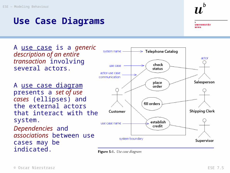
A use case is a generic description of an entire transaction involving several actors.
A use case diagram presents a set of use cases (ellipses) and the external actors that interact with the system.Dependencies and associations between use cases may be indicated.
© Oscar Nierstrasz
ESE — Modeling Behaviour
ESE 7.6
Using Use Case Diagrams
> “A use case is a snapshot of one aspect of your system. The sum of all use cases is the external picture of your system …”
— UML Distilled
> “As use cases appear, assess their impact on the domain model.”— Use cases can drive domain modeling by highlighting the
important concepts.

© Oscar Nierstrasz
ESE — Modeling Behaviour
ESE 7.7
Roadmap
> Use Case Diagrams> Sequence Diagrams> Collaboration (Communication) Diagrams> Statechart Diagrams
— Nested statecharts— Concurrent substates
> Using UML
© Oscar Nierstrasz
ESE — Modeling Behaviour
ESE 7.8
Scenarios
A scenario is an instance of a use case showing a typical example of its execution.
Scenarios can be presented in UML using either sequence diagrams or collaboration diagrams.
Note that a scenario only describes an example of a use case, so conditionality cannot be expressed!

© Oscar Nierstrasz
ESE — Modeling Behaviour
ESE 7.9
Sequence Diagrams
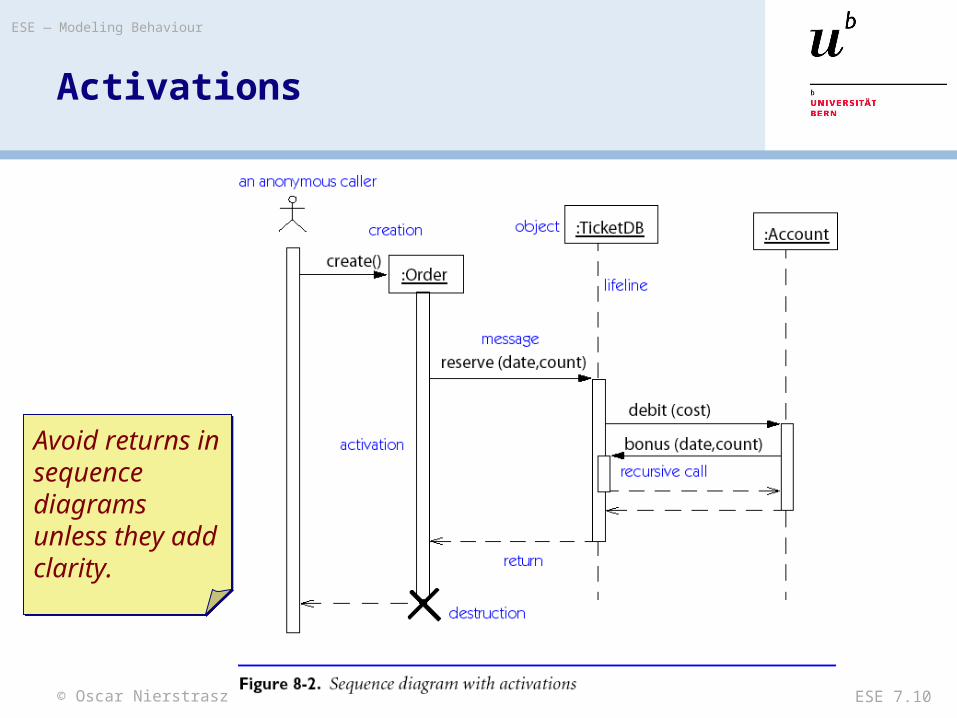
A sequence diagram depicts a scenario by showing the interactions among a set of objects in temporal order.
Objects (not classes!) are shown as vertical bars. Events or message dispatches are shown as horizontal (or slanted) arrows from the sender to the receiver.
© Oscar Nierstrasz
ESE — Modeling Behaviour
ESE 7.10
Activations
Avoid returns in sequence diagrams unless they add clarity.
Avoid returns in sequence diagrams unless they add clarity.

© Oscar Nierstrasz
ESE — Modeling Behaviour
ESE 7.11
Asynchrony and Constraints

© Oscar Nierstrasz
ESE — Modeling Behaviour
ESE 7.12
Roadmap
> Use Case Diagrams> Sequence Diagrams> Collaboration (Communication) Diagrams> Statechart Diagrams
— Nested statecharts— Concurrent substates
> Using UML
© Oscar Nierstrasz
ESE — Modeling Behaviour
ESE 7.13
Collaboration Diagrams
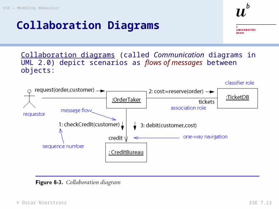
Collaboration diagrams (called Communication diagrams in UML 2.0) depict scenarios as flows of messages between objects:
© Oscar Nierstrasz
ESE — Modeling Behaviour
ESE 7.14
Message Labels
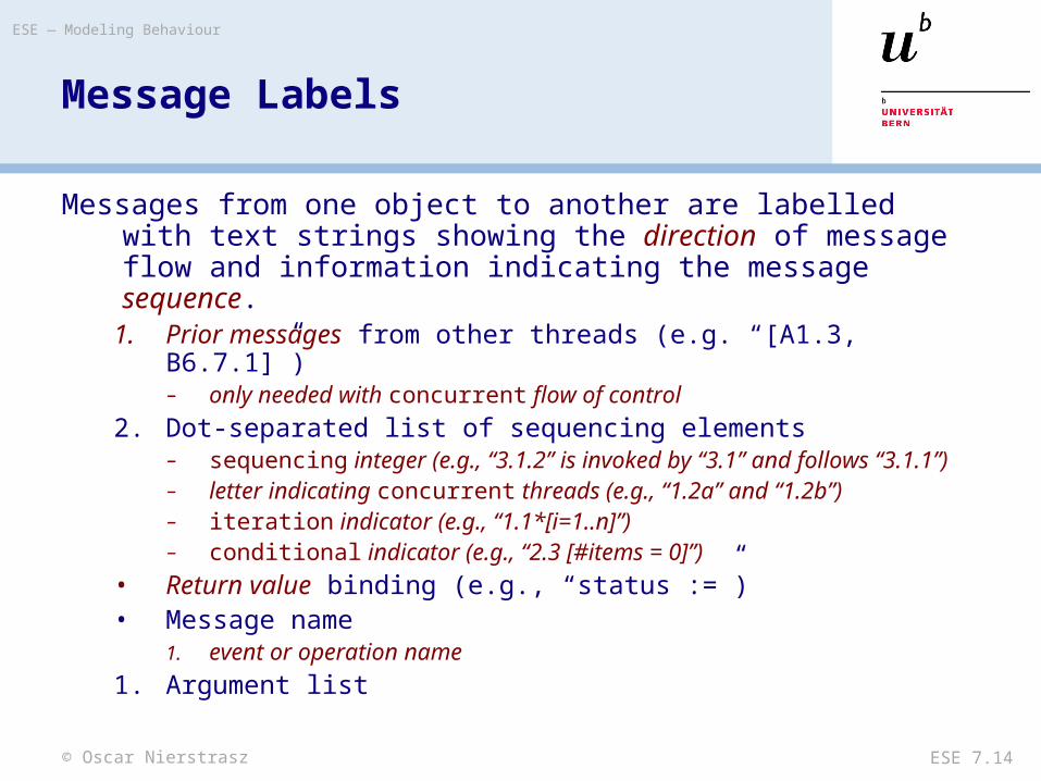
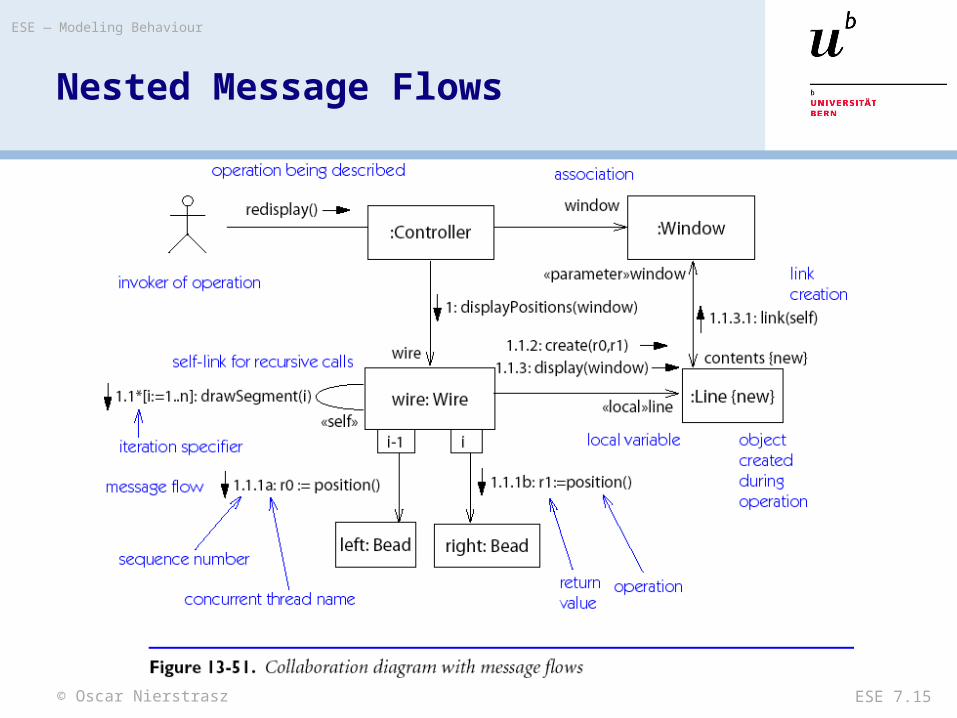
Messages from one object to another are labelled with text strings showing the direction of message flow and information indicating the message sequence.
1. Prior messages from other threads (e.g. “[A1.3, B6.7.1]”)– only needed with concurrent flow of control
2. Dot-separated list of sequencing elements– sequencing integer (e.g., “3.1.2” is invoked by “3.1” and follows “3.1.1”)– letter indicating concurrent threads (e.g., “1.2a” and “1.2b”)– iteration indicator (e.g., “1.1*[i=1..n]”)– conditional indicator (e.g., “2.3 [#items = 0]”)
• Return value binding (e.g., “status :=”)• Message name
1. event or operation name
1. Argument list
© Oscar Nierstrasz
ESE — Modeling Behaviour
ESE 7.15
Nested Message Flows
© Oscar Nierstrasz
ESE — Modeling Behaviour
ESE 7.16
Roadmap
> Use Case Diagrams> Sequence Diagrams> Collaboration (Communication) Diagrams> Statechart Diagrams
— Nested statecharts— Concurrent substates
> Using UML

© Oscar Nierstrasz
ESE — Modeling Behaviour
ESE 7.17
Statechart Diagrams

© Oscar Nierstrasz
ESE — Modeling Behaviour
ESE 7.18
Statechart Diagram Notation
A Statechart Diagram describes the temporal evolution of an object of a given class in response to interactions with other objects inside or outside the system.
An event is a one-way (asynchronous) communication from one object to another:— atomic (non-interruptible)— includes events from hardware and real-world objects e.g., message
receipt, input event, elapsed time, ...— notation: eventName(parameter: type, ...)
— may cause object to make a transition between states
© Oscar Nierstrasz
ESE — Modeling Behaviour
ESE 7.19
Statechart Diagram Notation ...
A state is a period of time during which an object is waiting for an event to occur:— depicted as rounded box with (up to) three sections:
– name — optional– state variables — name: type = value (valid only for that state)– triggered operations — internal transitions and ongoing operations
— may be nested

© Oscar Nierstrasz
ESE — Modeling Behaviour
ESE 7.20
State Box with Regions
The entry event occurs whenever a transition is made into this state, and the exit operation is triggered when a transition is made out of this state.The help and character events cause internal transitions with no change of state, so the entry and exit operations are not performed.
© Oscar Nierstrasz
ESE — Modeling Behaviour
ESE 7.21
Transitions
A transition is an response to an external event received by an object in a given state— May invoke an operation, and cause the object to change state— May send an event to an external object— Transition syntax (each part is optional):
event(arguments) [condition]/ ^target.sendEvent operation(arguments)
— External transitions label arcs between states— Internal transitions are part of the triggered operations of a state
© Oscar Nierstrasz
ESE — Modeling Behaviour
ESE 7.22
Operations and Activities
An operation is an atomic action invoked by a transition— Entry and exit operations can be associated with states
An activity is an ongoing operation that takes place while object is in a given state— Modelled as “internal transitions” labelled with the pseudo-event
do

© Oscar Nierstrasz
ESE — Modeling Behaviour
ESE 7.23
Roadmap
> Use Case Diagrams> Sequence Diagrams> Collaboration (Communication) Diagrams> Statechart Diagrams
— Nested statecharts— Concurrent substates
> Using UML

© Oscar Nierstrasz
ESE — Modeling Behaviour
ESE 7.24
Nested Statecharts
© Oscar Nierstrasz
ESE — Modeling Behaviour
ESE 7.25
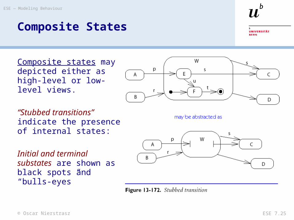
Composite States
Composite states may depicted either as high-level or low-level views.
“Stubbed transitions” indicate the presence of internal states:
Initial and terminal substates are shown as black spots and “bulls-eyes”
© Oscar Nierstrasz
ESE — Modeling Behaviour
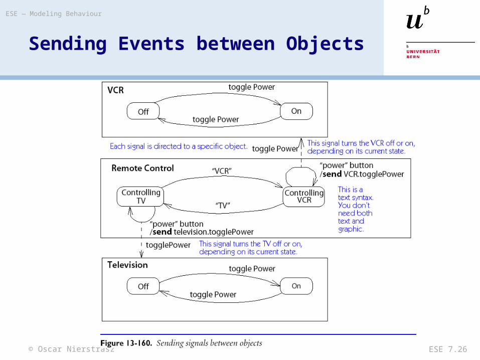
ESE 7.26
Sending Events between Objects

© Oscar Nierstrasz
ESE — Modeling Behaviour
ESE 7.27
Roadmap
> Use Case Diagrams> Sequence Diagrams> Collaboration (Communication) Diagrams> Statechart Diagrams
— Nested statecharts— Concurrent substates
> Using UML

© Oscar Nierstrasz
ESE — Modeling Behaviour
ESE 7.28
Concurrent Substates

© Oscar Nierstrasz
ESE — Modeling Behaviour
ESE 7.29
Branching and Merging
Entering concurrent states:Entering a state with concurrent substates means that each of the substates is entered concurrently (one logical thread per substate).
Leaving concurrent states:A labelled transition out of any of the substates terminates all of the substates.An unlabelled transition out of the overall state waits for all substates to terminate.


© Oscar Nierstrasz
ESE — Modeling Behaviour
ESE 7.31
Roadmap
> Use Case Diagrams> Sequence Diagrams> Collaboration (Communication) Diagrams> Statechart Diagrams
— Nested statecharts— Concurrent substates
> Using UML
© Oscar Nierstrasz
ESE — Modeling Behaviour
ESE 7.32
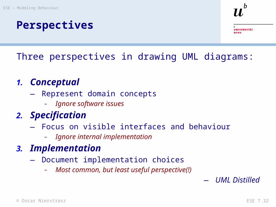
Perspectives
Three perspectives in drawing UML diagrams:
1. Conceptual— Represent domain concepts
– Ignore software issues
2. Specification— Focus on visible interfaces and behaviour
– Ignore internal implementation
3. Implementation— Document implementation choices
– Most common, but least useful perspective(!)
— UML Distilled
© Oscar Nierstrasz
ESE — Modeling Behaviour
ESE 7.33
Using the Notations
The diagrams introduced here complement class and object diagrams.
During Analysis:— Use case, sequence and collaboration diagrams document use cases
and their scenarios during requirements specification
During Design:— Sequence and collaboration diagrams can be used to document
implementation scenarios or refine use case scenarios— State diagrams document internal behaviour of classes and must be
validated against the specified use cases
© Oscar Nierstrasz
ESE — Modeling Behaviour
ESE 7.34
What you should know!
> What is the purpose of a use case diagram?> Why do scenarios depict objects but not classes?> How can timing constraints be expressed in scenarios?> How do you specify and interpret message labels in a
scenario?> How do you use nested state diagrams to model object
behaviour?> What is the difference between “external” and “internal”
transitions?> How can you model interaction between state diagrams
for several classes?

© Oscar Nierstrasz
ESE — Modeling Behaviour
ESE 7.35
Can you answer the following questions?
> Can a sequence diagram always be translated to an collaboration diagram?
> Or vice versa?> Why are arrows depicted with the message labels rather
than with links?> When should you use concurrent substates?
© Oscar Nierstrasz
ESE — Modeling Behaviour
ESE 7.36
License
> http://creativecommons.org/licenses/by-sa/2.5/
Attribution-ShareAlike 2.5You are free:• to copy, distribute, display, and perform the work• to make derivative works• to make commercial use of the work
Under the following conditions:
Attribution. You must attribute the work in the manner specified by the author or licensor.
Share Alike. If you alter, transform, or build upon this work, you may distribute the resulting work only under a license identical to this one.
• For any reuse or distribution, you must make clear to others the license terms of this work.• Any of these conditions can be waived if you get permission from the copyright holder.
Your fair use and other rights are in no way affected by the above.