Embed Size (px)
Citation preview

P R O D U C T O V E R V I E W
z u k e n . c o m / E 3 s e r i e s
Z u k e n – T h e P a r t n e r f o r S u c c e s s ®
E ³ . s e r i e s – E l e c t r i c a l W i r i n g , C o n t r o l S y s t e m s a n d F l u i d E n g i n e e r i n g S o f t w a r e
Z u k e n – T h e P a r t n e r f o r S u c c e s s
2 Product Overview | www.zuken.com®
solution for product development from concept to physical realization and outputs for manufacturing.
Standard interfaces make it possible to import and export multiple data formats such as DXF/DWG, TIFF, GIF, JPG, PDF, SVG, DGN, CGM, VRML, STEP AP203/214, STEP AP212/KBL and STEP AP212/ELOG.
E³.series is available in different configurations as a node locked or floating license that can be accessed by mulitple users. In the configuration E3.enterprise, several users can work simultaneously on large projects, with all modifications being visible in real time to all users. E3.enterprise comprises integrated user and access management capabilities.
E³.series made up of five main modules:
• E3.schematic – design and documentation of electrical control system schematics
• E3.cable – cabling design and documentation
• E3.fluid – hydraulic, pneumatic, cooling and Lubrication System Design
• E³.panel – cabinet and panel layout in 2D und 3D
• E3.formboard – creation of manufacturing documentation.
The main toolsets of the E³.series suite of applications are now described in more detail.
E3.series is a Windows-based, scalable, easy-to-learn system for the design of wiring and control systems, hydraulics and pneumatics. The out-of-the-box solution includes E3.schematic (for circuit and fluid diagrams), E3.cable (for advanced electrical and fluid design), E3.panel (for cabinet and panel layout), and E3.formboard (for 1:1 wiring harness manufacturing drawings).
An object-oriented systems architecture built on a central database for all applications ensures continuous synchronization of all engineering stages. E³.series projects contain all views of an electrical and/or fluid system:
• schematic and cable plans
• fluid plans
• panel layouts
• formboard drawings
• bills of material
• outputs to manufacturing
• built in real-time design rule checks
• assembly and service documentation.
With bidirectional interfaces into leading MCAD toolsets, and a large selection of modules for specific applications, E3.series is a complete design engineering
E3.series includes applications for schematic, fluid, cable planning, cabinet and formboard layout.
Fluid planSchematic
BOM Cabinet and panel layout
Formboard Wiring diagram
Object-orienteddatabase
Online rule checks
Version/changecontrol
®
✔
✔
✔
E ³ . s e r i e s
3
E³.schematic – design and documentation of electrical control system schematicsE³.schematic is core to all E³.series modules and provides electrical engineers with an easy-to-use solution for designing and documenting electrical control systems including schematic diagrams, terminal plans and PLCs. Its object-oriented architecture provides an integrated and consistent design approach to help eliminate errors, improve quality and reduce design time.
E³.series includes built in real-time design rule checks that prevent errors rather than finding them later. The intelligent component-based parts library ensures only real parts are used and helps drive the design with automatic part selections.
E3.schematic base functionality includes:
• Device duplication prevention
• Short circuit prevention
• Design reuse with centrally stored sub-circuits or modules
• Automatic and parallel connections
• Save, load, copy, rotate and mirror drawings and areas
• Extensive functionality for exchanging symbols and components
• Component driven intelligent parts libraries
• Ensure only valid parts are used in the design
• Simple and complex variants and option management
• Online cross-references for connections and devices
• Object and text hyperlinks
• User-defined attributes
• User-defined grid sizes, fonts and line types
• Dynamic zooming and panning.
E³.schematic manages all design data including affiliated documents, such as bill of materials and connection lists or assembly instructions and datasheets. Its object-oriented data structure ensures manufacturing instructions always match the design data.
Terminal strips imported from electronic component configurators provided by the leading component vendors can be ordered and used as pre-assembled parts. Alternatively, terminal strips that were configured in E³.series can be transferred to the terminal configurator where they are verified and processed.
E³.schematic enables configuration of the wire numbers in the project based on circuit functionality and signal classification. The utility is configurable for a number of additional industries, including machinery, rail and power.
E³.Functional Design is an extension of E³.series that supports the development of the first sketches, which can be used to drive the detailed wiring and fluid plans. In the early development phases, block diagrams are created and connected through specified communication channels. Then functional units, with their signal properties, are placed in dynamic components.
E³.eCheck is an extension to E³.series that enables users to functionally analyze their electrical schematic circuits and check designs for fuse and wire sizing errors. The utility works in real-time and provides instant feedback on the operability of the circuit design. E³.eCheck is ideally suited to those working with DC control systems, such as transportation companies.
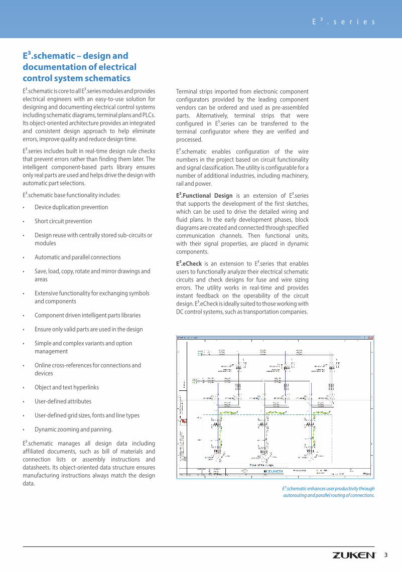
E³.schematic enhances user productivity through autorouting and parallel routing of connections.

Z u k e n – T h e P a r t n e r f o r S u c c e s s
4 Product Overview | www.zuken.com®
E³.cable supports block functionality. Blocks can represent components, rack equipment, black boxes, PCBs and through hierarchy whole systems and sub-systems. Connector pins are dynamically added to the blocks and signal information is displayed alongside.
Blocks can represent hierarchical systems and sub-systems, so users can tunnel down into blocks to the level below and signals and connections can pass between levels and sub-levels. Hierarchy enables top-down and bottom-up design, promotes design reuse, and provides managers with a system-level overview.
Special representations of connectors, as used in the aerospace and automotive industries, can be created automatically using the extension E³.ExtendedConnectorHandling.
E³.cable – cabling design and documentationE³.cable is an extension of E³.schematic that is used for the design and documentation of cable plans and harness layouts. Individual conductors can be combined in the design to form new cables or harnesses. Shielding and twisted-pair structure can also be added to the cables and automatically shown in the schematic.
Views allow alternate documentation of devices such as single-line diagrams, wiring diagram and cable plans. For example connectors can be represented as single pins in the schematic and then as the complete connector in the cable plan. Changes to any of the views immediately updates all other views, ensuring all documentation is synchronized.
With the intelligent block functionality in E³.cable terminals, connectors and any devices can be placed inside a funtional block functional. Hierarchy within a block is unique to E³.series and offers many productivity benefits.
E ³ . s e r i e s
5
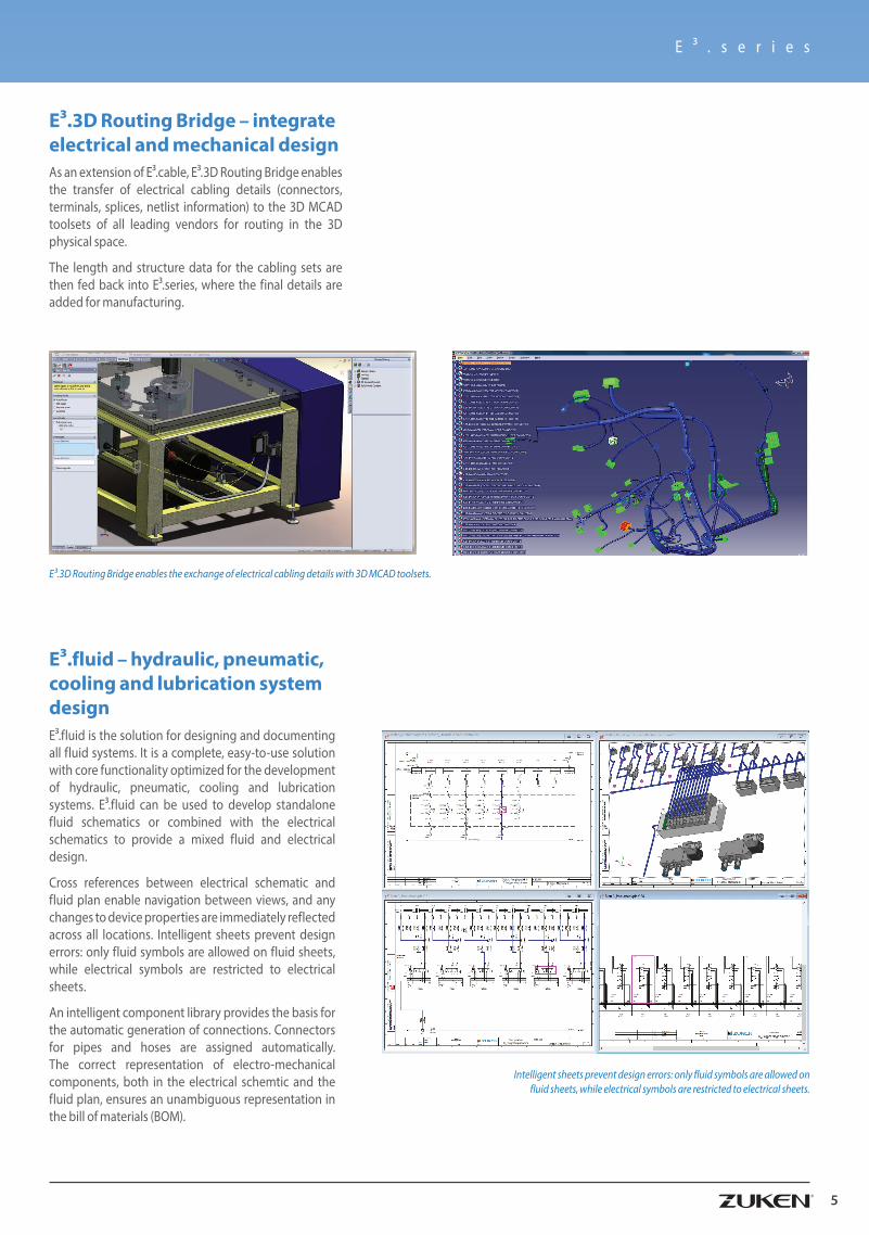
E³.3D Routing Bridge – integrate electrical and mechanical design As an extension of E³.cable, E³.3D Routing Bridge enables the transfer of electrical cabling details (connectors, terminals, splices, netlist information) to the 3D MCAD toolsets of all leading vendors for routing in the 3D physical space.
The length and structure data for the cabling sets are then fed back into E³.series, where the final details are added for manufacturing.
E³.fluid – hydraulic, pneumatic, cooling and lubrication system designE³.fluid is the solution for designing and documenting all fluid systems. It is a complete, easy-to-use solution with core functionality optimized for the development of hydraulic, pneumatic, cooling and lubrication systems. E³.fluid can be used to develop standalone fluid schematics or combined with the electrical schematics to provide a mixed fluid and electrical design.
Cross references between electrical schematic and fluid plan enable navigation between views, and any changes to device properties are immediately reflected across all locations. Intelligent sheets prevent design errors: only fluid symbols are allowed on fluid sheets, while electrical symbols are restricted to electrical sheets.
An intelligent component library provides the basis for the automatic generation of connections. Connectors for pipes and hoses are assigned automatically. The correct representation of electro-mechanical components, both in the electrical schemtic and the fluid plan, ensures an unambiguous representation in the bill of materials (BOM).
Intelligent sheets prevent design errors: only fluid symbols are allowed on fluid sheets, while electrical symbols are restricted to electrical sheets.
E³.3D Routing Bridge enables the exchange of electrical cabling details with 3D MCAD toolsets.
Z u k e n – T h e P a r t n e r f o r S u c c e s s
6 Product Overview | www.zuken.com®
Simplified models of the electrical E³.panel design are used to check for collisions in the complete mechanical design. This functionality enables full digital mock-ups to assess spacing requirements, clash detection and error prevention.
Using the E³.series extension E³.3D Routing Bridge, schematic and connection information from E³.series can be interfaced to all major MCAD systems. Collaborating between E³.series and your chosen MCAD tool allows concurrent design. Mechanical engineers and electrical engineers can work independently or collaboratively.
The E³.series extension E³.Revision Management ensures all changes are tracked and documented. Alternate revisions of the design are compared against each other and any changes are reported and stored in both graphical and textual formats.
Manufacturing data is extracted from the design in the form of wire lists, which includes route and length information. In addition various modules exist, which interface E³.panel to manufacturing equipment such as Komax wire preparation machinery and Perforex drilling, punching and cutting tools.
E³.panel – cabinet and panel layout in 2D and 3DWorking in either two or three dimensions, E³.panel allows engineers to layout components inside panel enclosures. Intelligent automatic snapping points allow parts to be easily placed in their correct location, and with keep-out and height restrictions it is also possible to prevent clashes. The ease-of-use means electrical engineers do not need to understand MCAD tools.
E³.panel is dynamically integrated with the schematic design and work can begin either in the panel or the schematic. Users can easily navigate between the panel and schematic and changes to either are immediately reflected across both.
Wires can be automatically routed through ducts in the panel, taking into account the shortest route and any segregation requirements. Duct fill capacity is also checked. The length of each wire is calculated and with dedicated links to wire preparation machines wires can be cut stripped, crimped and marked automatically.
Using VRML or STEP AP203/214 all 3D data in E³.panel can be transferred to 3D mechanical systems.
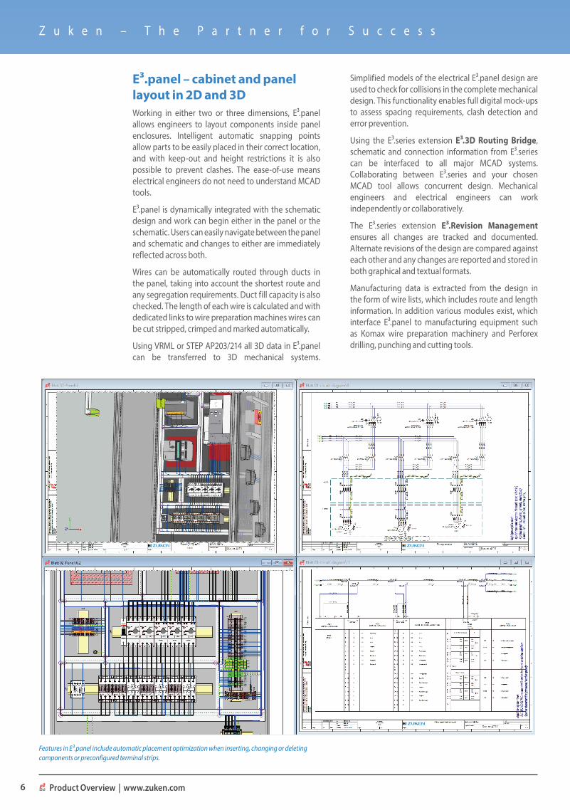
Features in E³.panel include automatic placement optimization when inserting, changing or deleting components or preconfigured terminal strips.
E ³ . s e r i e s
7
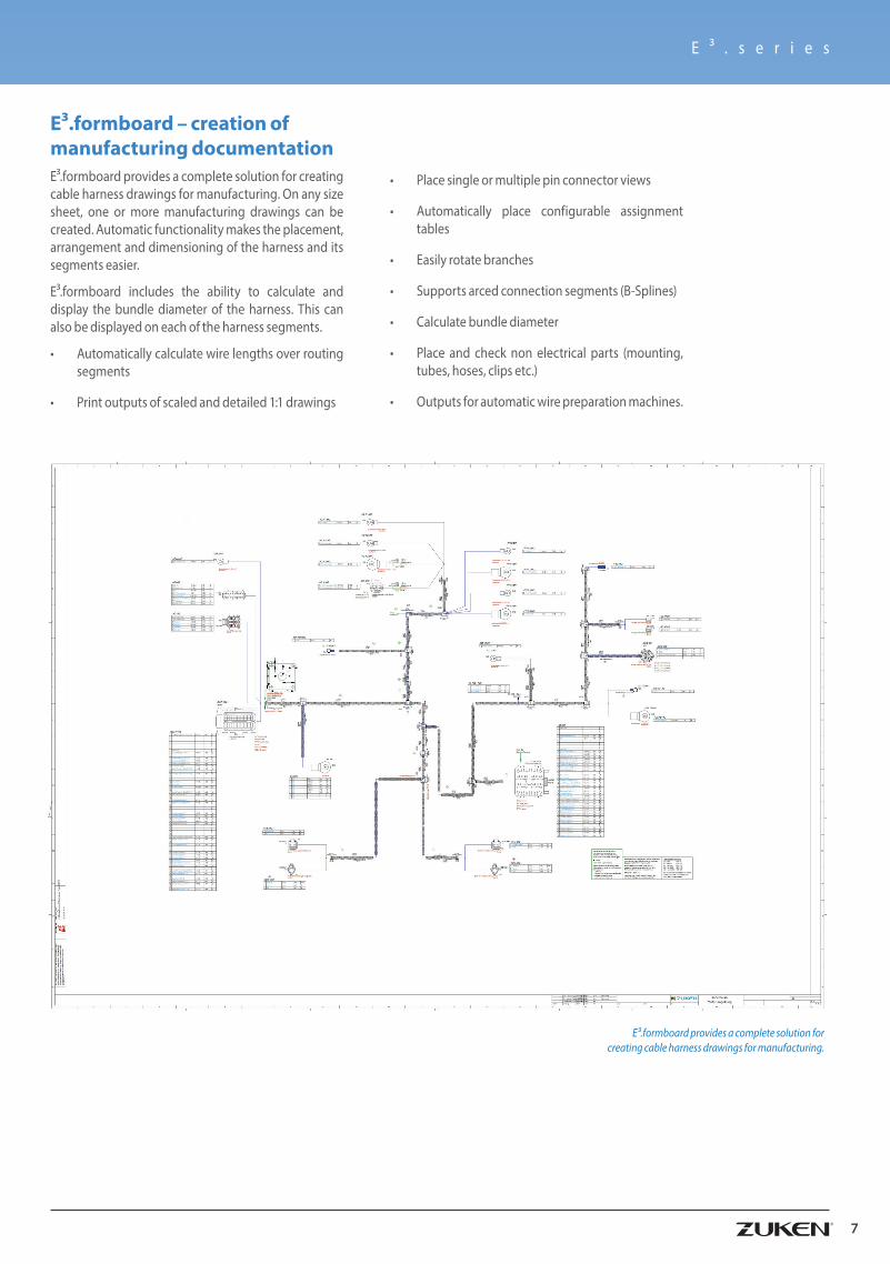
E³.formboard – creation of manufacturing documentationE³.formboard provides a complete solution for creating cable harness drawings for manufacturing. On any size sheet, one or more manufacturing drawings can be created. Automatic functionality makes the placement, arrangement and dimensioning of the harness and its segments easier.
E³.formboard includes the ability to calculate and display the bundle diameter of the harness. This can also be displayed on each of the harness segments.
• Automatically calculate wire lengths over routing segments
• Print outputs of scaled and detailed 1:1 drawings
E³.formboard provides a complete solution for creating cable harness drawings for manufacturing.
• Place single or multiple pin connector views
• Automatically place configurable assignment tables
• Easily rotate branches
• Supports arced connection segments (B-Splines)
• Calculate bundle diameter
• Place and check non electrical parts (mounting, tubes, hoses, clips etc.)
• Outputs for automatic wire preparation machines.
Z u k e n – T h e P a r t n e r f o r S u c c e s s
8 Product Overview | www.zuken.com®
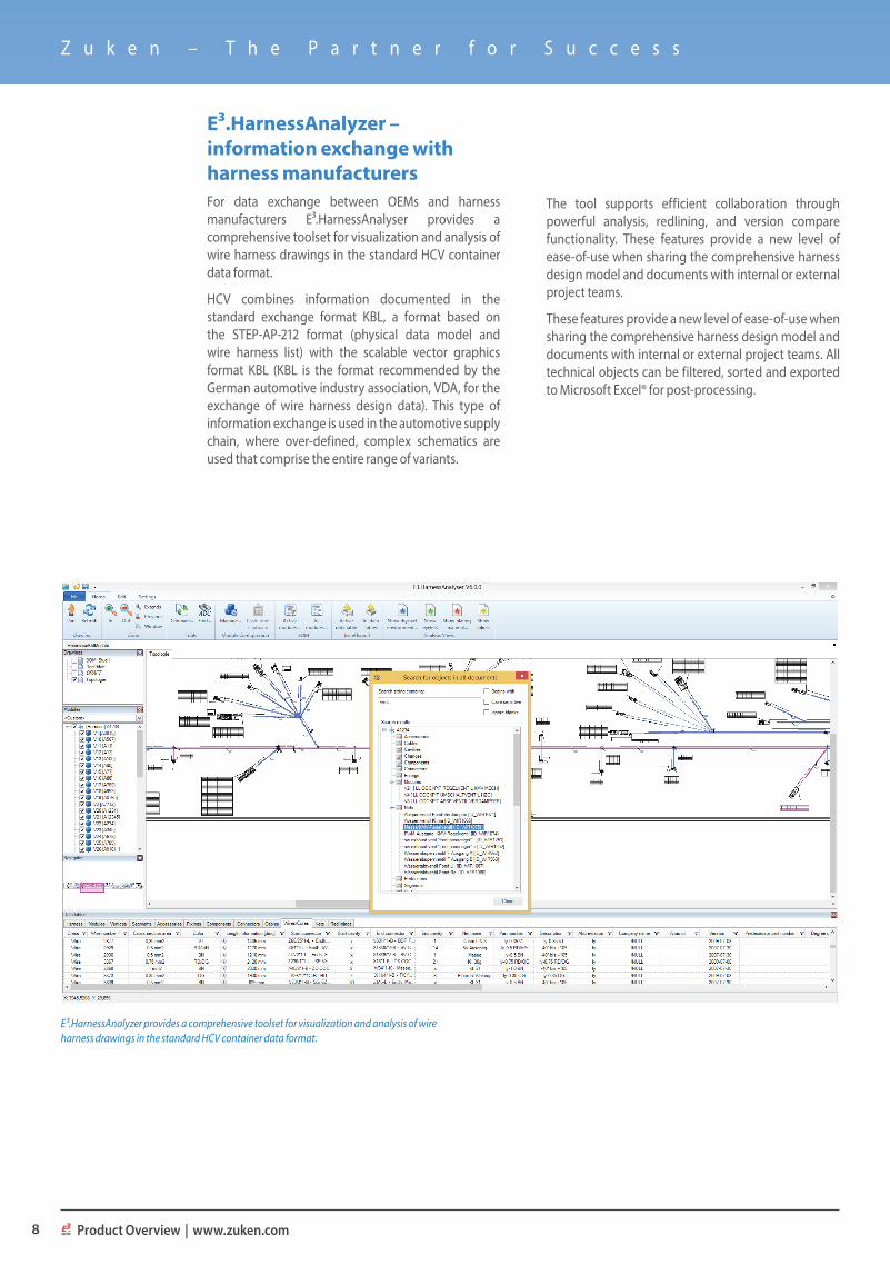
E³.HarnessAnalyzer – information exchange with harness manufacturersFor data exchange between OEMs and harness manufacturers E³.HarnessAnalyser provides a comprehensive toolset for visualization and analysis of wire harness drawings in the standard HCV container data format.
HCV combines information documented in the standard exchange format KBL, a format based on the STEP-AP-212 format (physical data model and wire harness list) with the scalable vector graphics format KBL (KBL is the format recommended by the German automotive industry association, VDA, for the exchange of wire harness design data). This type of information exchange is used in the automotive supply chain, where over-defined, complex schematics are used that comprise the entire range of variants.
The tool supports efficient collaboration through powerful analysis, redlining, and version compare functionality. These features provide a new level of ease-of-use when sharing the comprehensive harness design model and documents with internal or external project teams.
These features provide a new level of ease-of-use when sharing the comprehensive harness design model and documents with internal or external project teams. All technical objects can be filtered, sorted and exported to Microsoft Excel® for post-processing.
E³.HarnessAnalyzer provides a comprehensive toolset for visualization and analysis of wire harness drawings in the standard HCV container data format.
E ³ . s e r i e s
Library, design data and change managment E³.series is complemented by a data and process management environment that is closely integrated with the toolsets. It natively manages E³.series engineering project data and libraries as well as the E³.series engineering workflow process.
The environment is designed to support the native E³.series data model and directly supports E³.series data objects, E³.series libraries and the E³.series environment. It uses role-based process and workflow management for support of typical electrical engineering roles such as designers, system architects, library managers, project and program managers.
With the ability to create snapshots of the project, document changes, and roll-back to previous versions when necessary, the solution enables users to track and manage changes across different versions and configurations of a project.
For electrical engineers, the data and process management capabilities are a seamless extension to the existing E³.series work environment. By using the native E³.series data model, designs are managed on a sheet and device level, enabling engineers to work the way they prefer to work, rather than adapting their work process to third party PDM tools.
Project managers benefit from integrated engineering workflow support, resource management and project management capabilities. IT managers are provided with a solution which can be integrated into their existing PLM and ERP systems, and is scalable to the unique and dynamic requirements of each company.
9

P R O D U C T O V E R V I E W
Z u k e n – T h e P a r t n e r f o r S u c c e s s
G e t t o k n o w Z u k e n
About ZukenZuken is a global provider of leading-edge software and consulting services for electrical and electronic design and manufacturing. Founded in 1976, Zuken has the longest track record of technological innovation and financial stability in the electronic design automation (EDA) software industry. The company’s extensive experience, technological expertise and agility, combine to create world-class software solutions. Zuken’s transparent working practices and integrity in all aspects of business produce long-lasting and successful customer partnerships that make Zuken a reliable long-term business partner.
Zuken is focused on being a long-term innovation and growth partner. The security of choosing Zuken is further reinforced by the company’s people—the foundation of Zuken’s success. Coming from a wide range of industry sectors, specializing in many different disciplines and advanced technologies, Zuken’s people relate to and understand each company’s unique requirements.
For more information about the company and its products, visit www.zuken.com.
z u k e n . c o m / E 3 s e r i e sAll trademarks mentioned are the property of their respective owners. Copyright © Zuken GmbH. 161019