Embed Size (px)
Citation preview

DESIGN CONSIDERATIONS FOR OPENJOINT
RAINSCREEN CLADDING SYSTEMS
STÉPHANE HOFFMAN, PENG, AND JOSÉ ESTRADA, RRO, EIT MORRISON HERSHFIELD
10900 NE 8th Street, Suite 810, Bellevue WA 98004
Phone: 4252895926 • Fax: 4252895958
Email: [email protected] and [email protected]
SS YYMMPP OO SS II UU MM OONN BB UU II LL DD II NN GG EE NN VV EE LL OO PP EE TT EE CC HHNN OO LL OO GG YY •• OOCC TT OO BB EERR 22 00 11 11 HH OO FF FF MMAA NN AA NN DD EE SS TT RR AA DD AA •• 8811

ABSTRACT
Recent years have seen an increased trend toward rainscreen cladding systems for the benefits they offer in terms of rainwater management. These systems typically consist of an exterior cladding, a drainage cavity, and a back-up weather-resistive barrier. Traditionally in rainscreen cladding designs, the joints in the exterior cladding are sealed to minimize the potential for water intrusion into the drainage cavity, with the exceptions of weeps and pres-sure-equalization vents, which are generally sheltered from water ingress. However, recent trends in the design of exterior claddings have seen an increased use of open-jointed rain-screen cladding systems. In these systems, the joints between the cladding elements are intentionally left open. This paper will discuss the implications of open joints for the per-formance of rainscreen systems. Various approaches to the design of open-jointed rain-screen cladding systems will be discussed, and some case studies demonstrating the detail-ing of open-jointed cladding systems will be presented. The three case studies that are pre-sented are newly constructed buildings; and, although no issues have been identified to date, the long-term performance of their open-joint cladding has yet to be established. Because of this constraint, this paper does not attempt to compare the performance of the different approaches outlined in the case studies.
SPEAKERS
STÉPHANE P. HOFFMAN, PENG — MORRISON HERSHFIELD, BELLEVUE, WA
STÉPHANE P. HOFFMAN, PEng, is employed in the building engineering group of Morrison Hershfield (MH) as an engineer specializing in building envelope design, rehabili-tation, and restoration. His background includes a mix of structural engineering, building science, and architecture. Stéphane holds a master of engineering degree from McGill University and a master of architecture degree from the Université de Montréal. He has been involved in building condition surveys, investigation of building envelope problems, design review, field-testing of building envelope components, and extensive design review and field review.
JOSÉ F. ESTRADA, RRO, EIT — MORRISON HERSHFIELD, BELLEVUE, WA
JOSÉ F. ESTRADA, RRO, EIT, is employed in the building engineering group of Morrison Hershfield (MH) as an engineering consultant specializing in building envelope design, reha-bilitation, and restoration. He holds a bachelor of applied science degree from the University of Toronto and has been involved with MH in building envelope condition surveys, forensic investigations of building envelope problems, design review for new construction projects, and field testing of building envelope components. Projects include low-rise condominiums, high-rise condominiums, schools, hospitals, commercial buildings, and government build-ings in various climate zones.
88 22 •• HH OO FF FF MMAA NN AA NN DD EE SS TT RR AA DD AA SSYYMM PP OO SS II UUMM OONN BB UU II LL DD II NN GG EE NN VV EE LL OO PP EE TT EE CC HHNNOO LL OO GG YY •• OO CC TT OO BB EE RR 22 00 1111

DESIGN CONSIDERATIONS FOR OPENJOINT
RAINSCREEN CLADDING SYSTEMS
INTRODUCTION Rainscreen cladding has become com-
mon in building envelope design in North America because of its effective perfor-mance in mitigating moisture-related dam-age. This type of cladding includes three main components:
• A continuous water-shedding sur-face: cladding that acts as the first line of defense for direct precipita-tion.
• A drainage cavity: an open space to allow drainage of any water getting past the cladding and that is vented to encourage drying.
• A concealed air and weather barrier: a membrane that acts as a second line of defense for moisture intru-sion further into the wall assembly and often also serves as the air bar-rier for the assembly.
In an increasing trend, architects are designing open-joint rainscreen cladding assemblies for new buildings. This is large-ly on account of the aesthetic appeal of this type of cladding. Such cladding assemblies can be defined as wall assemblies that employ the basic principles of a traditional rainscreen, with the exception that the joints between the cladding elements are left open–effectively compromising the con-tinuity of the cladding as a water-shedding surface and increasing the burden of wea-thertightness on the underlying weather-resistive barrier (WRB).
Though several studies on the advan-tages of traditional rainscreen assemblies exist, there appears to be a lack of any sci-entifically based research into the perfor-mance of open-joint rainscreen assemblies. There are some unknowns that arise when introducing open joints into a rainscreen assembly. These variables include:
• Water: the influence of the open joints on increased water entry into the drainage cavity and, in some cases, the increased reliance on the weather-resistive barrier as the sole line of defense against water pene-tration
• Air: the influence on drying poten-
tial and on the limited thermal resis-tance of the air space as a result of the increased venting area and the increased potential for wind-wash-ing effect on insulation installed in the drainage cavity
• Light: the effects of increased ultra-violet radiation on materials within the drainage cavity
• Fire: increased exposure to compo-nents within the cavity
• Foreign Bodies: the increased ease with which insects and debris can enter into the cavity
We have observed a number of approaches to use when it comes to the design and installation of this type of cladding. Each approach addresses these unknowns differently. These approaches can be largely broken down into two main categories. The first is to use open joints and modify the underlying assembly to accommodate the new demands identified above. The second is to modify the exterior cladding assembly itself, giving the cladding the appearance of open joints without actu-ally leaving the joints completely open. Our observations have led us to identify five dis-tinct installation methods that appear to be used when designing an open-joint rain-screen. We have defined them as:
• Open-cavity rainscreen • Deep-cavity rainscreen • Baffled-joint rainscreen • Simulated open-joint rain-
screen • Dual WRB rainscreen
This paper briefly describes all of these methods and elaborates further on three examples we recently experi-enced. The case examples described include the open-cavity rainscreens, baffled-joint rainscreens, and the dual WRB rainscreens.
DESIGN APPROACHES OPENCAVITY RAINSCREEN
The method that currently ap-pears to be most commonly employed is the open-cavity rainscreen
approach. This design is essentially a typi-cal rainscreen assembly without sealant at the joints and with few or no modifications to account for the increased demand on the underlying assembly as a result of the open joints. In some installations, a secondary layer of WRB has been installed to coincide with the open joints of the cladding and conceal the main WRB. Although this has been largely done for the aesthetic reason of providing black-colored joints, it has the added benefit of protecting the main WRB at the most exposed locations from ultraviolet radiation and from direct exposure to the weather. Figure 1 provides an example of a typical open-cavity rainscreen assembly where a strip of additional WRB was installed at the open joints.
Open-cavity rainscreens have also been installed at exterior-insulated wall assem-blies. Figure 2 shows examples of an exterior-insulated wall assembly where a weather-and UV-tolerant insulation such as rock wool has been installed on the exterior of the WRB and left exposed at the open joints.
To an extent, the performance of any wall in terms of moisture mitigation can be related to its level of exposure. For example, a wall under a large overhang is less likely to experience moisture-related failures than an exposed wall with no overhang. For instances with low exposure to wind-driven rain and under large overhangs, open-cavi-ty rainscreen assemblies may be a viable option. However, the true performance of
Figure 1 – Typical window head interface in an opencavity rainscreen.
SS YYMMPP OO SS II UU MM OONN BB UU II LL DD II NN GG EE NN VV EE LL OO PP EE TT EE CC HHNN OO LL OO GG YY •• OOCC TT OO BB EERR 22 00 11 11 HH OO FF FF MMAA NN AA NN DD EE SS TT RR AA DD AA •• 8833

Figure 2 – View of typical halfinch joint in the exterior insulated open joint assembly.
these systems will not be fully understood until further observation of and research on existing systems have occurred. At the moment, owners and installers tend to use this method of installation because it offers the desired aesthetic appeal at a relatively low initial cost.
Figures 3A and 3B – Typical joint in cladding. Notice that a 3/8in joint in the cladding is left open at the vertical and horizontal panel. In the field, “z” furring was installed at the vertical joints, as is shown in the photo.
Case Study of OpenCavity Rainscreen We were recently involved in two pro-
jects where differing variations on the open-cavity rainscreen were used over a signifi-cant portion of the wall area. In both cases, the joints in the cladding assembly were left open for aesthetic purposes, with minimal change in the underlying assembly to account for the increased loads that may be associated with open-joint cladding. The cli-mate conditions in the area for both pro-jects are considered temperate and humid, with rainfall distributed largely over the winter months in the form of low-intensity, long-lasting precipitation.
OpenCavity Example In one project, a high-rise medical
building with moderate exposure to wind-driven rain used an open-joint panelized wood-panel cladding. The open-joint rain-screen panels at this project were used in conjunction with a number of other cladding and glazing assemblies. The main
penetrations in the open-joint-clad walls were punch windows. See Figures 1, 3A, and 3B.
Design Intent: The open joint cladding at this
project included the following assem-bly from the exterior to the interior: • Panelized wood cladding (with
open 3/8-in joints) • Drainage cavity (7/8 in) • Sheet-applied vapor-permeable
air- and weather-resistive barrier
• Vertical open joints; an additional strip of WRB was loosely attached
• Horizontal joints; a strip of sheet metal was installed
• Exterior sheathing • Foil-faced batt insulation • Interior sheathing
While this project was in the design phase, the design team, along with the WRB manufacturer, had originally recommended the addition of a secondary WRB to protect the field air and weather barrier from possi-ble premature deterioration as a result of the open joints. Application of a secondary WRB would have essentially turned this open cavity rainscreen into a dual WRB open-joint rainscreen assembly. After dis-cussion with the client and considering cost pressures on the project, a compromise was reached in which the addition of a sec-ondary strip of WRB was applied only at the vertical open joints. Ultimately, the addi-tional WRB at the joints was installed for aesthetic reasons, as the owner did not want the field WRB (which was orange) to be visible through the joints. The additional layer of WRB was black. At the horizontal joints, a black-colored sheet metal was installed to close the joint. This was done so that vertical fastening (z-girts) could be installed continuously, onto which the cladding was applied.
Detailing Punch windows in the open-cavity rain-
screen were detailed at the wall interfaces with a metal surround. At the head, this metal surround served an additional capacity as a through-wall head flashing. The joint between the metal flashing and the cladding was left open to maintain aesthetics, while the joint between the flashing and the window frame was sealed with caulking and backer rod. As designed and installed, this detailing relies heavily on the WRB, metal flashing, and the exterior seal at the win-dow frame to deflect and resist moisture.
88 44 •• HH OO FF FF MMAA NN AA NN DD EE SS TT RR AA DD AA SSYYMM PP OO SS II UUMM OONN BB UU II LL DD II NN GG EE NN VV EE LL OO PP EE TT EE CC HHNNOO LL OO GG YY •• OO CC TT OO BB EE RR 22 00 1111

½
¼
³⁄
³⁄ ½
EXTERIOR INSULATED Figures 4A and 4B – Typical interface of OPENCAVITY thinstone, openjoint cladding with curtain EXAMPLE wall at jamb (top) and at the sill (below).
In another recent Jamb: A 3/8in joint has been left open at project, an open-cavity this interface. Sill: The thinstone cladding rainscreen system was has been mounted into the curtain wall installed at portions of a frame at the sill and sealed to it. A joint in high-rise higher-educa- the frame itself with a flexible gasket tion building in the allows for movement in the curtain wall Seattle area. Open-joint and maintains the openjoint appearance. stone veneer panels were installed over an exterior insulated wall assembly. Penetrations in the open-joint-clad sections of this building were minimal; however, the wall does interface with a curtain wall system, with the wall membrane sealed the curtain wall and to the frame of the glazing system. See maintaining the open Figures 2 and 4. joint aesthetic of the
thin-stone cladding. Design Intent The decision to simulate
The open-joint cladding portions of the the joint at this inter-building envelope included the following face was made because assembly from the exterior to the interior: of the critical nature of
• Thin-stone panels (with open -in the sill interface. With a joints) simulated open joint,
• Drainage cavity ( -in) water running down the • Rock wool exterior insulation (3 in) • Liquid-applied membrane water-
proofing (this membrane acts as the air/moisture and vapor barrier and is sealed to the curtain wall)
• Concrete masonry unit (CMU) wall
As an open-cavity assembly, this method of installation may be incremental-ly more durable than the nonexterior insu-lated open-cavity rainscreen mentioned pre-viously. This is because the main WRB is also a waterproof membrane and is there-fore more able to address extended wetting than a vapour-permeable WRB. During the design phase, as with the other examples of open-cavity rainscreens, we had originally recommended the addition of a secondary WRB layer to protect the insulation and other underlying assemblies; however, the client opted to simply use a relatively UV-stable exterior insulation and leave it exposed at the joints.
Detailing Curtain wall sill: At the curtain wall sill,
the thin-stone panels were mounted into the curtain wall frame and sealed to it. A joint within the curtain wall itself, which is baffled with a flexible gasket, served the dual purpose of allowing for deflection in
surface of the window is less likely to drip into the drainage cavity at this joint.
Curtain wall jamb: At curtain wall jamb interfaces, the cladding was not mounted into the curtain wall as it was at the sill. Instead, a 8-in joint was left open between the cladding and the curtain wall frame. The open joint at the jamb exposes the framing of the curtain wall beyond, and a flexible membrane flashing was installed from the cur-tain wall frame to the field WRB to maintain the contin-uous air and weather barrier. The window jamb remains a critical joint, albeit slightly less critical than that at the sill; so to minimize water entry into the cavity at this interface, the size of the open joint was reduced to 8 in, which is smaller than the typical -in joint that is typi-cal throughout.
DEEPCAVITY RAINSCREEN A method similar to the
open-cavity rainscreen is the deep-cavity rainscreen with open joints. The main differ-
ence with this approach is that it includes a drainage cavity of 5 to 6 inches in depth. See Figure 5. This is much deeper than the drainage cavity in a typical rainscreen of approximately 1 inch or less. The intent of this design is to place the cladding out far enough from the WRB to reduce the expo-sure to wind-driven rain to the exterior sheathing, without overextending the clad-
Figure 5 – Schematic of proposed deep cavity rainscreen.
SS YYMMPP OO SS II UU MM OONN BB UU II LL DD II NN GG EE NN VV EE LL OO PP EE TT EE CC HHNN OO LL OO GG YY •• OOCC TT OO BB EERR 22 00 11 11 HH OO FF FF MMAA NN AA NN DD EE SS TT RR AA DD AA •• 8855
½
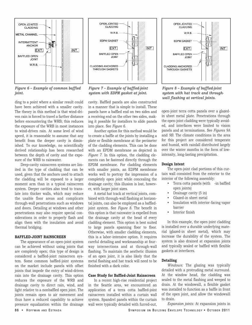
Figure 6 – Example of common baffled joint.
ding to a point where a similar result could have been achieved with a smaller cavity. The theory in this method is that wind-dri-ven rain is forced to travel a farther distance before encountering the WRB; this reduces the exposure of the WRB in most instances to wind-driven rain. At some level of wind speed, it is reasonable to assume that any benefit from the deeper cavity is dimin-ished. To our knowledge, no scientifically derived relationship has been researched between the depth of cavity and the expo-sure of the WRB to rainwater.
Deep-cavity rainscreen systems are lim-ited in the type of cladding that can be used, given that the anchors used to attach the cladding will be exposed to a larger moment arm than in a typical rainscreen system. Deeper cavities also tend to trans-late into thicker walls, which may reduce the usable floor areas and complicate through-wall penetrations such as windows and doors. Detailing at windows and other penetrations may also require special con-siderations in order to properly flash and align them with the insulation and avoid thermal bridging.
BAFFLEDJOINT RAINSCREEN The appearance of an open-joint system
can be achieved without using joints that are completely open; this type of design is considered a baffled-joint rainscreen sys-tem. Some common baffled-joint systems on the market include panels with offset joints that impede the entry of wind-driven rain into the drainage cavity. This option reduces the exposure of the WRB and drainage cavity to direct rain, wind, and light relative to a nonbaffled open joint. The joints remain open to air movement and thus have a reduced capability to achieve pressure equalization within the drainage
Figure 7 – Example of baffledjoint system with EDPM gasket at joint.
cavity. Baffled panels are also constructed in a manner that is simple to install. These panels have a baffled end on two sides and a receiving end on the other two sides, mak-ing it possible for installers to slide panels into place. See Figure 6.
Another option for this method would be to create a baffle at the joints by installing a plate or flexible membrane at the perimeter of the cladding elements. This can be done with an EPDM membrane as depicted in Figure 7. In this option, the cladding ele-ments can be fastened directly through the EPDM membrane. For cladding elements with smaller joints, an EDPM membrane works well to portray the impression of a completely open joint while concealing the drainage cavity; this illusion is lost, howev-er, with larger joint sizes.
A metal hat track at vertical joints, com-bined with through-wall flashing at horizon-tal joints, can also be employed as a baffled-joint system. See Figure 8. The benefit in this option is that rainwater is expelled from the drainage cavity at the head of every cladding element. This option is best suited to large panels spanning floor to floor. Otherwise, with smaller cladding elements, this is a labor-intensive option. It requires careful detailing and workmanship at four-way intersections and at through-wall flashing. To maintain the aesthetic illusion of an open joint, it is also likely that the metal flashing and hat track will need to be finished with a dark color.
Case Study for BaffledJoint Rainscreen In a recent high-rise residential project
in the Seattle area, we encountered an application of a terra cotta baffled-joint rainscreen installed within a curtain wall system. Spandrel panels within the curtain wall were typically detailed with furred-out,
Figure 8 – Example of baffledjoint system with hat track and throughwall flashing at vertical joints.
open-joint terra cotta panels over a glazed-in sheet metal plate. Penetrations through the open-joint cladding were typically avoid-ed, and interfaces were limited to vision panels and at terminations. See Figures 9A and 9B. The climate conditions in the area for this project are considered temperate and humid, with rainfall distributed largely over the winter months in the form of low-intensity, long-lasting precipitation.
Design Intent The open-joint clad portions of this cur-
tain wall consisted from the exterior to the interior of the following assembly:
• Terra cotta panels (with -in baffled open joints)
• Drainage cavity (5 in) • Glazed-in sheet metal • Insulation with interior-facing vapor
barrier • Interior finish
In this example, the open-joint cladding is installed over a durable underlying mate-rial (glazed-in sheet metal), which may increase the durability of the system. The system is also drained at expansion joints and typically sealed or baffled with flexible gaskets at interfaces.
Detailing Windows: The glazing was typically
detailed with a protruding metal surround. At the window head, the cladding was sealed to the metal flashing and weeped to drain. At the windowsill, a flexible gasket was installed to function as a baffle in front of the open joint, and allow the windowsill to drain.
Expansion joints: At expansion joints in
88 66 •• HH OO FF FF MMAA NN AA NN DD EE SS TT RR AA DD AA SSYYMM PP OO SS II UUMM OONN BB UU II LL DD II NN GG EE NN VV EE LL OO PP EE TT EE CC HHNNOO LL OO GG YY •• OO CC TT OO BB EE RR 22 00 1111

”
sealed
face
Figures 9A and 9B – Example of baffled openjoint rainscreen used in a curtain wall. This detail illustrates the typical fastening mechanism and ½in open joints. An expansion joint in the curtain wall with a ¾in dynamic joint is also shown. At the expansion joint, a flexible gasket is installed at the curtain wall frame.
elements themselves are open, but their connection to the continuous substrate per-forms as if it were a closed-joint system. The joints of the substrate itself could then be
the curtain wall, a ¾-in joint in the cladding was left open to allow for movement in the system. A dual-compression gasket at the frame forms a rainscreen at this interface.
Simulated OpenJoint Rainscreen One method of creating an appearance
of an open-joint rainscreen assembly with-out necessarily creating open joints is to create an open-joint façade over a continu-ous substrate. See Figure 10. This method can be ideal if the cladding element panel sizes are relatively small, requiring many open joints. In this installation method, cladding elements, typically some form of cultured stone, can be glued or mechanical-ly attached to the face of a cement board or some other robust substrate, such as a scratch layer of stucco on a wire mesh, and then installed over a typical rainscreen assembly. The joints between the cladding
Figure 10 – Example of simulated openjoint rainscreen (section view).
and treated as closed-joint while maintaining the appearance of an open-joint assembly. This method of installation provides a continuous water shedding sur-
and continuous protection for the drainage cavity while maintaining the desired open-joint appearance. One possi-ble limitation of this approach is that the open joints in this assembly may be prone to efflorescence from dissolved salts, and in cold climates, they may be subject to freeze-thaw damage if water accumulates within the open joint.
Dual WRB Rainscreen The creation of a two-stage WRB behind
the cladding can be applied to help mitigate the increased demand of the underlying assembly. This dual barrier is constructed by installing an airtight second-line-of-defense layer under a primary water-shed-
ding layer of WRB. The WRB is installed behind the cladding, sepa-rated from it with a drainage cavity. Of the observed “true open-joint rainscreen methods, this is our pre-ferred method because of the conti-nuity that it offers while providing the desired aesthetic effect. See Figure 11.
The theory behind this method of installation is that the primary water-shedding surface layer of WRB will perform the function of the cladding, particularly in areas near open joints. The cladding itself is assumed to function as a noncontin-uous screen. The water-shedding WRB should be loose-laid to allow
for drainage but anchored at regular inter-vals to prevent displacement. This design allows for a continuous water-shedding surface, a drainage medium, and a second
Figure 11 – Section view of proposed dual WRB rainscreen assembly.
SS YYMMPP OO SS II UU MM OONN BB UU II LL DD II NN GG EE NN VV EE LL OO PP EE TT EE CC HHNN OO LL OO GG YY •• OOCC TT OO BB EERR 22 00 11 11 HH OO FF FF MMAA NN AA NN DD EE SS TT RR AA DD AA •• 8877

⁄
½
line-of-defense WRB, while maintaining the appearance of an open-joint rainscreen assembly.
The cladding is then installed on the exterior of the water-shedding surface with a typically sized drainage cavity, separating it from the water-shedding surface. As with the deep-cavity rainscreen assembly, the cladding used in this method should be carefully considered, particularly when including a layer of rigid insulation. Though the drainage cavity itself is likely no deeper than a traditional rainscreen, the distance that any anchors span may increase with thicker insulation.
Case Study for Dual WRB Rainscreen We were recently involved in a project
that employed the dual WRB approach for the main open-joint rainscreen cladding. The project was a three-level office building with one level of below-grade parking and inset glazing. The ground floor of the build-ing was mainly clad in aluminum-framed curtain wall that was in plane with the open-joint rainscreen cladding in the above floors. The climate conditions in this area are considered temperate and humid, with rainfall distributed largely over the winter months in the form of low-intensity, long-lasting precipitation.
Figure 12 – Schematic of dual WRB system at project near Seattle, WA.
Design Intent The open-joint cladding
portion of the building enve-lope included the following assembly, from the exterior to the interior:
• Thin-stone panels • Drainage cavity (15 8
in) • Loose-laid, sheet-
applied, WRB • Exterior insulation
(1 in) • Liquid-applied air
and WRB • Exterior sheathing • Foil-faced batt insu-
lation • Interior finish
The mechanically at-tached, sheet-applied WRB acted as the primary water-shedding surface and was taped at the seams to main-tain continuity. The liquid-
Figure 13 – Schematic of dual WRB system at project near Seattle, WA.
applied WRB behind the exterior insulation performed the function of the main air barrier and second line of defense for the envelope.
Interfaces and penetrations statistically tend to be more susceptible to instances of localized moisture-related failure, relative to
the field envelope con-ditions in most build-ing envelopes. As such, in developing the design of this type of cladding, a more conservative approach was taken near inter-faces. Detailing at this project was largely simplified due to a number of factors, the most obvious of which was the lack of diverse penetrations within the open-joint cladding. Penetrations through the open-joint rain-screen consisted al-most entirely of win-dows that were signifi-cantly inset. See Fig ure 12 for schematic of assembly.
Detailing Recessed Curtain Walls
The inset windows were generally sepa-rated from the cladding by a metal sur-round that ran perpendicular to the open-joint cladding and to the window frame at the sill, jambs, and head. This inset further simplified the detailing required to provide a seal from the window frame to the liquid-applied air and weather barrier.
At the interface of the windows, open joints were simulated with a black gasket. This created the appearance of an open joint while maintaining redundancies in water shedding at this often-difficult inter-face. The overhang formed by the soffit at the head of the window further protected the window interfaces. A cross-cavity flash-ing was installed at the soffit created by the metal surround at the head of the window bridging from the liquid-applied WRB to the exterior. Figure 13 illustrates the detailing used at the window head in greater detail.
At the windowsill, gaskets were installed at the glazing interface with the metal sur-round and at the interface between the metal surround and the top of the thin-stone open-joint cladding. Below the metal surround, the sheet-applied WRB extended up to the window, and a waterproofing membrane was installed over the horizontal exterior sheathing below the exterior insula-tion. Figure 14 illustrates the sill detailing.
88 88 •• HH OO FF FF MMAA NN AA NN DD EE SS TT RR AA DD AA SSYYMM PP OO SS II UUMM OONN BB UU II LL DD II NN GG EE NN VV EE LL OO PP EE TT EE CC HHNNOO LL OO GG YY •• OO CC TT OO BB EE RR 22 00 1111
’
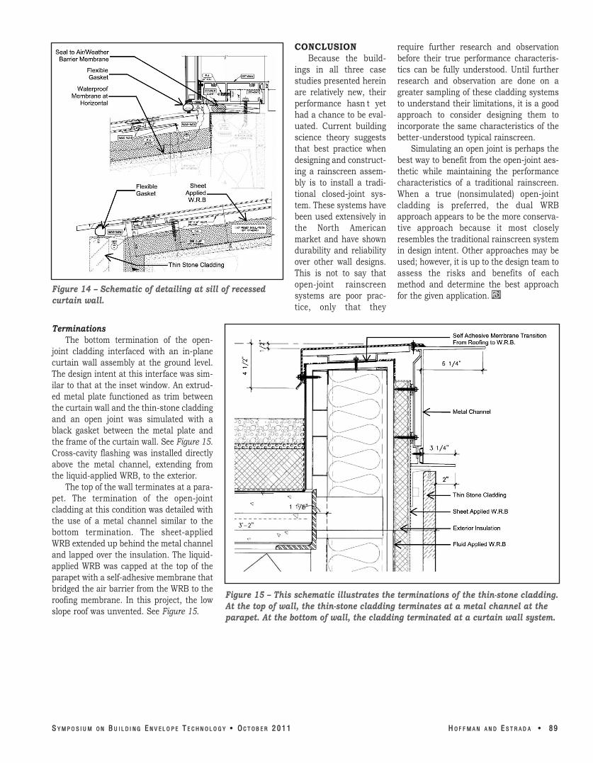
Figure 14 – Schematic of detailing at sill of recessed curtain wall.
Terminations The bottom termination of the open-
joint cladding interfaced with an in-plane curtain wall assembly at the ground level. The design intent at this interface was sim-ilar to that at the inset window. An extrud-ed metal plate functioned as trim between the curtain wall and the thin-stone cladding and an open joint was simulated with a black gasket between the metal plate and the frame of the curtain wall. See Figure 15. Cross-cavity flashing was installed directly above the metal channel, extending from the liquid-applied WRB, to the exterior.
The top of the wall terminates at a para-pet. The termination of the open-joint cladding at this condition was detailed with the use of a metal channel similar to the bottom termination. The sheet-applied WRB extended up behind the metal channel and lapped over the insulation. The liquid-applied WRB was capped at the top of the parapet with a self-adhesive membrane that bridged the air barrier from the WRB to the roofing membrane. In this project, the low slope roof was unvented. See Figure 15.
CONCLUSION require further research and observation Because the build- before their true performance characteris-
ings in all three case tics can be fully understood. Until further studies presented herein research and observation are done on a are relatively new, their greater sampling of these cladding systems performance hasn t yet to understand their limitations, it is a good had a chance to be eval- approach to consider designing them to uated. Current building incorporate the same characteristics of the science theory suggests better-understood typical rainscreen. that best practice when Simulating an open joint is perhaps the designing and construct- best way to benefit from the open-joint aes-ing a rainscreen assem- thetic while maintaining the performance bly is to install a tradi- characteristics of a traditional rainscreen. tional closed-joint sys- When a true (nonsimulated) open-joint tem. These systems have cladding is preferred, the dual WRB been used extensively in approach appears to be the more conserva-the North American tive approach because it most closely market and have shown resembles the traditional rainscreen system durability and reliability in design intent. Other approaches may be over other wall designs. used; however, it is up to the design team to This is not to say that assess the risks and benefits of each open-joint rainscreen method and determine the best approach systems are poor prac- for the given application. tice, only that they
Figure 15 – This schematic illustrates the terminations of the thinstone cladding. At the top of wall, the thinstone cladding terminates at a metal channel at the parapet. At the bottom of wall, the cladding terminated at a curtain wall system.
SS YYMMPP OO SS II UU MM OONN BB UU II LL DD II NN GG EE NN VV EE LL OO PP EE TT EE CC HHNN OO LL OO GG YY •• OOCC TT OO BB EERR 22 00 11 11 HH OO FF FF MMAA NN AA NN DD EE SS TT RR AA DD AA •• 8899

99 00 •• HH OO FF FF MMAA NN AA NN DD EE SS TT RR AA DD AA SSYYMM PP OO SS II UUMM OONN BB UU II LL DD II NN GG EE NN VV EE LL OO PP EE TT EE CC HHNNOO LL OO GG YY •• OO CC TT OO BB EE RR 22 00 1111