Embed Size (px)
Citation preview

Manuale installatoreInstaller Manual
ESM2/ESM2.120/ESM2.D/ESM2.D.120/ESM2.W/ESM2.W.120Attuatore scorrevole 24 Vdc
Sliding actuator 24 Vdc

2
ACTO
IT
Indice ............................................................................................................................................................................................................. Pagina1 Caratteristiche generali ........................................................................................................................................................................................12 Caratteristiche tecniche .......................................................................................................................................................................................13 Predisposizione per impianto elettrico .................................................................................................................................................................14 Verifiche preliminari ..............................................................................................................................................................................................15 Dimensioni e ingombro ........................................................................................................................................................................................26 Installazione del motoriduttore .............................................................................................................................................................................27 Fissaggio del motoriduttore .................................................................................................................................................................................38 Installazione della cremagliera .............................................................................................................................................................................49 Sblocco manuale...................................................................................................................................................................................................6

1VIMAR group
ACTO
IT
4 Verifiche preliminariPer un corretto funzionamento dell’automazione la struttura del cancello esistente, o da realizzare, deve presentare i seguenti requisiti:- Le ruote del cancello siano montate in posizione tale da dare stabilità al cancello stesso e che siano in buono stato ed efficienti.- La rotaia sia libera diritta e pulita in tutta la sua lunghezza con battute d’arresto obbligatorie sia in apertura che in chiusura.- La guida superiore sia in asse con la rotaia, i pattini siano integri e lubrificati e con un gioco di circa 1 mm. per parte in modo da
facilitare lo scorrimento dell’anta.- Gli spazi tra le parti mobili e le parti fisse del cancello siano di entità prevista dalle norme nazionali o comunque siano ricondotti ai
canoni di sicurezza applicando un adeguato sistema di protezione.- Il peso del cancello non deve superare i 600 Kg- Assenza di serrature meccaniche di chiusura. Si raccomanda di effettuare gli interventi necessari per garantire l’affidabilità e la sicurezza dell’automazione
1 Caratteristiche generaliAutomazione, ACTO 600D, per cancelli scorrevoli residenziali e condominiali ad uso intensivo. L’attuatore elettromeccanico irreversibile è dotato di un motore in bassa tensione, 24 Vdc, e uno sblocco meccanico che permette di aprire e chiudere il cancello manualmente. Il motore aziona un gruppo riduttorre, lubrificato con grasso permanente, racchiuso in una fusione d’alluminio di grosso spessore ma di ridottissimo ingombro. La scheda elettro-nica di comando è integrata al corpo dell’attuatore, con la predisposizione per l’alloggiamento della batteria tampone (opzionale).
2 Caratteristiche tecniche
230 V~
3
2
11
45
Legenda
1- Fotocellule
2- Selettore
3- Lampeggiante
4- Motoriduttore
5- Cremagliera
230 V~120 V~
3 Predisposizione per impianto elettrico (impianto standard)
Alimentazione ESM2 230 Vac (+10%, -10%)ESM2.120 120 Vac (+10%, -10%)
Frequenza 50-60 HzAlimentazione scheda 22 VacAlimentazione motore 24 VdcFrequenza di utilizzo Servizio intensivoPotenza nominale motore 50 WVelocità massima motore 1300 RPMCremagliera Modulo 4Temperatura di esercizio Da -25°C a +55°CGrado di protezione IP45Rumorosità < 70dBAPeso massimo cancello 600 KgDimensioni (LxHxP) 308x270x225 mm

2
ACTO
6 Installazione del motoriduttore
Fig. 1
308 188 37
270
5 Dimensioni e ingombro
Fig. 2.1 Fig. 2.2
Togliere il carter del motoriduttore Sbloccare girando il pomello in senso orario per 5 giri
Prima del fissaggio dell’attuatore verificare la distanza tra il cancello e il pignone (vedi figura 3).
40
63
Fig. 3
Automazione
8088
207
328

3VIMAR group
ACTO
7 Fissaggio del motoriduttoreIndividuato il luogo dove installare il motoriduttore (che può essere alla destra o alla sinistra del cancello), è possibile fissare il motore con due tasselli oppure utilizzare la contropiastra in due modi:1) muratura della piastra (Fig. 4A- Fig. 4B)2) fissaggio nel suolo tramite 4 tasselli (non in dotazione)N.B. La contropiastra deve essere murata o fissata seguendo scrupolosamente le misure indicate in fig. 3 per garantire il corretto ingranamento tra il pignone del motoriduttore e la cremagliera.
Muratura della piastraa. Piegare le 3 zanche Fig. 4Ab. Posizionare la contropiastra in modo che la zanca centrale sia verso il pignone del motoriduttore (quindi verso la cremagliera) Fig. 4B particolare A.c. Inserire le due viti, M8x30, in dotazione nei fori quadrati della piastra e fissarle tramite i dadi in modo da incastrarle nel quadro, Fig. 4B particolare C.d. Utilizzare dei tubi flessibili, necessari per il passaggio dei cavi di collegamento (accessori - alimentazione elettrica). Passare i tubi flessibili tra i fori, Fig. 4B particolare B. I tubi devono uscire circa 5 cm dai fori della piastra.e. Murare perfettamente in piano la contropiastra.
Fissaggio con tasselliPreparare una piazzola piana di tenace calcestruzzo di area sufficiente a coprire la contropiastra.N.B. Si consiglia di realizzare una piazzola che sporga di qualche centimetro dal livello del suolo per evitare che il motoriduttore sia interessato dal ristagno o dal deflusso di acqua piovana.- Seguire il punto c e d.- Fissare la contropiastra con 4 tasselli da fondazione, M8x120 mm Fig. 4B particolare D non in dotazione, e stringere le viti utilizzando le rondelle (i
tasselli permettono la regolazione della piastra in altezza).
Regolazione in altezza e fissaggio dell’attuatore:
L’attuatore è dotato di un sistema di regolazione dell’altezza in modo da rendere agevole la regolazione del gioco tra pignone e cremagliera e in modo da poter compensare eventuali abbassamenti del binario senza agire sulle regolazioni della cremagliera.Per regolare l’altezza e fissare l’attuatore procedere nel seguente modo:
- Predisporre i cavi La base dell’attuatore è dotata di 4 dadi posizionati nella parte inferiore della fusione del motoriduttore a fianco delle asole di fissaggio. Avvitare ai
dadi attraverso gli appositi fori i 4 grani forniti (Fig. 4C).- Posizionare il motoriduttore rispettando le misure indicate nella Fig. 3. Appoggiare il motoriduttore sulla contropiastra in modo che le viti, M8x30,
entrino nelle due asole di fissaggio della fusione (Fig. 4D).- Agire sui grani per regolare correttamente l’altezza dell’attuatore garantendo il corretto gioco con la cremagliera e assicurando che l’attuatore sia in
bolla- Definita la posizione desiderata, posizionare le rondelle fornite sulle viti di fissaggio M8x30, serrare l’attuatore alla piastra mediante i due dadi M8
forniti.
B
A
C
D
DFig. 4A Fig. 4B Fig. 4C Fig. 4D

4
ACTO
Prima di iniziare l’installazione della cremagliera controllare i fermi meccanici del cancello, nel caso non siano presenti o non robusti è necessario installarli (vedi figura 6)
8 Installazione della cremaglieraNel caso si utilizzi la cremagliera ad avvitare si consiglia di assemlare i moduli per verificare che i punti di fissaggio non combacino con il movimento delle ruote di scorrimento (vedi figura 7).
Fig. 7
Fig. 6.1 Fig. 6.2
TAPPO
FORCELLA
VISTA FRONTALE FERMO BATTUTA CANCELLO
- Si deve garantire un gioco di 1,5 mm. tra pignone e cremagliera su tutta la lunghezza del cancello (Fig. 8). Per regolare il gioco tra pignone e cremagliera fare riferimento al paragrafo Regolazione in altezza e fissaggio dell’attuatore.
Per regolare il gioco tra pignone e cremagliera fare riferimento al paragrafo Regolazione in altezza e fissaggio dell’attuatore.
N.B.: questa operazione è molto importante per il funzionamento e la durata del motoriduttore. Infatti è opportuno che il carico del cancello non gravi sul pignone perchè potrebbe danneggiare l’automazione.
1,5 mm ottenuti al termine della regolazione
Fissaggio della cremagliera Dopo aver sbloccato l’attuatore chiudere completamente il cancello (vedi immagine di Fig. 2.2). Appoggiare la cremagliera al pignone del motoriduttore. Prima di forare per il fissaggio controllare che le viti non vadano in corrispondenza delle
ruote di scorrimento.
Fig. 8
OK NO NOOK OK OK OK OK

5VIMAR group
ACTO
Fig. 9
Fissare tramite le viti il secondo elemento della cremagliera e ripetere la procedura per la lunghezza totale del cancello.
Iniziare il fissaggio del primo metro di cremagliera, spostando il cancello manualmente verso l’apertura verificando che appoggi correttamente con il pignone dell’attuatore.
Accostare il secondo elemento della cremagliera al precedente, utilizzando un pezzo di cremagliera per allineare correttamente le dentature dei 2 elementi (vedi figura 9).
Installazione dei finecorsa magneticiSbloccare manualmente il motoriduttore, portare il cancello nel punto di massima apertura, fissare la staffa del finecorsa Sx in modo che il magnete sia in corrispondenza al sensore, portare il cancello nel punto di massima chiusura, fissare la staffa del finecorsa Dx in modo che il magnete si in cor-rispondenza al sensore (vedi figura 10-11).
Fig. 10

6
ACTO
Marrone Bianco Marrone Nero
Blu
24 Vdc
Finecorsa magnetico
Fig.11
9 Sblocco manuale Per sbloccare manualmente il motore inserire il pomello e girare in senso orario per 5 volte.
Eseguire i cablaggi elettrici e la programmazione della centrale di comando. A collaudo ultimato, inserire il carter dell’attuatore e fissare la vite di tenuta carter (Fig. 12), inserire il pomello e fissare la vite (Fig. 13), inserire portello di sblocco (Fig. 14).
Fig. 12 Fig. 13Fig. 14
M

7VIMAR group
ACTO
DICHIARAZIONE CE DI CONFORMITÀ(Dichiarazione di incorporazione di quasi-macchine allegato IIB Direttiva 2006/42/CE)
No.:ZDT00432.00
Il sottoscritto, rappresentante il seguente costruttore
Elvox SpAVia Pontarola, 14/A - 35011 Campodarsego
(PD) Italy
dichiara qui di seguito che i prodotti
ATTUATORI PER CANCELLI AD ANTE SCORREVOLI - SERIE ACTO
Articoli ESM1 (ACTO 400D), ESM2 (ACTO 600D)
risultano in conformità a quanto previsto dalla(e) seguente(i) direttiva(e) comunitaria(e) (comprese tutte le modifiche applicabili) e che sono state applicate tutte le seguenti norme e/o specifiche tecniche
Direttiva BT 2006/95/CE: EN 60335-2-103 (2003) + A11 (2009)Direttiva EMC 2004/108/CE: EN 61000-6-1 (2007), EN 61000-6-3 (2007) + A1 (2011)Direttiva R&TTE 1999/5/CE: EN 301 489-3 (2002), EN 300 220-3 (2000)Direttiva Macchine 2006/42/CE EN 13241 (2003) + A1 (2011), EN 12453 (2000)
Dichiara inoltre che la messa in servizio del prodotto non deve avvenire prima che la macchina finale, in cui deve essere incorporato, non è stata dichiarata conforme, se del caso, alle disposizioni della Direttiva 2006/42/CE.
Dichiara che la documentazione tecnica pertinente è stata costituita da Elvox SpA, è stata compilata in conformità all’allegato VIIB della Direttiva 2006/42/CE e che sono stati rispettati i seguenti requisiti essenziali: 1.1.1, 1.1.2, 1.1.3, 1.1.5, 1.1.6, 1.2.1, 1.2.2, 1.2.6, 1.3.1, 1.3.2, 1.3.3, 1.3.4, 1.3.7, 1.3.8, 1.3.9, 1.4.1, 1.4.2, 1.5.1, 1.5.2, 1.5.4, 1.5.5, 1.5.6, 1.5.7, 1.5.8, 1.5.9, 1.6.1., 1.6.2, 1.7.1, 1.7.2, 1.7.3, 1.7.4.
Si impegna a presentare, in risposta ad una richiesta adeguatamente motivata delle autorità nazionali, tutta la necessa-ria documentazione giustificativa pertinente al prodotto.
Campodarsego, 29/04/2013
L’Amministratore Delegato
Nota: Il contenuto di questa dichiarazione corrisponde a quanto dichiarato nell’ultima revisione della dichiarazione ufficiale disponibile prima della stampa di questo manuale. Il presente testo è stato adattato per motivi editoriali. Copia della dichiarazione originale può essere
richiesta a Elvox SpA
8
ACTO
Contents: .................................................................................................................................................................................................................... Page1 General features ...................................................................................................................................................................................................... 92 Technical characteristics ......................................................................................................................................................................................... 93 Electrical system set-up .......................................................................................................................................................................................... 94 Preliminary checks .................................................................................................................................................................................................. 95 Dimensions and clearance ...................................................................................................................................................................................... 106 Installing the gear motor ......................................................................................................................................................................................... 107 Securing the gear motor ........................................................................................................................................................................................ 118 Installing the rack .................................................................................................................................................................................................... 129 Manual release ........................................................................................................................................................................................................ 16

9VIMAR group
ACTO
4 Preliminary checksFor the automatic gate system to function properly, the structure of the existing gate, or the one to be made, must meet the following requirements:- The wheels of the gate are mounted in such a position as to provide stability to the gate and are in a good condition and efficient.- The rail is clear, straight and clean throughout its length with mandatory stops for both opening and closing.- The top guide is aligned with the rail, the sliding blocks are intact and lubricated and with a clearance of approximately 1 mm. on
each side so as to facilitate the sliding of the gate leaf.- The spaces between the moving and fixed parts of the gate are of the size required by the national standards or in any case
comply with safety standards by applying an adequate protection system.- The weight of the gate must not exceed 600 kg- No mechanical closing locks. It is recommended to take the necessary steps to ensure the reliability and safety of the automatic gate system
1 General featuresACTO 600D automatic gate system for heavy-use residential and condominium sliding gates. The non-reversible, electromechanical actuator is equipped with a low-voltage 24 Vdc motor and a mechanical release which enables the gate to be opened and closed manually. The motor operates a gear unit, lubricated with permanent grease, which is enclosed in a thick but extremely compact die-cast aluminium housing. The electronic control board is integrated in the body of the actuator, with the provision of a housing for the back-up battery (optional).
2 Technical characteristics
3 Electrical system set-up (standard system)
230 V~
3
2
11
45
Key1- Photocells2- Selector switch3- Flashing light4- Gear motor5- Rack
230 V~120 V~
Supply voltage ESM2 230 Vac (+10%, -10%)ESM2.120 120 Vac (+10%, -10%)
Frequency 50-60 HzBoard voltage supply 22 VacMotor voltage supply 24 VdcFrequency of use Heavy duty serviceRated motor power 50 WMaximum motor speed 1300 RPMRack Module 4Operating temperature From -25°C to +55°CProtection rating IP45Noise < 70dBAMaximum gate weight 600 kgDimensions (WxHxD) 308x270x225 mm

10
ACTO
6 Installing the gear motor
Fig. 1
Fig. 2.1 Fig. 2.2
Remove the gear motor casing Unlock by rotating the knob clockwise by 5 full turns
5 Dimensions and clearance
308 188 37
270
8088
40
63
Fig. 3
Automatic gate system
Before securing the actuator, check the distance between the gate and the pinion (see figure 3).
207
328

11VIMAR group
ACTO
Securing the gear motorAfter identifying the place where you are going to install the gear motor (which can be to the right or left of the gate), you can secure the motor with two wall plugs or use the backplate in two ways:1) walling up the plate (Fig. 4A- Fig. 4B)2) securing in the ground by means of 4 wall plugs (not supplied)N.B.: The backplate must be walled up or secured by carefully following the measurements shown in Fig. 3 to ensure correct meshing between the pinion of the gear motor and the rack.
Walling up the platea. Bend the 3 anchors Fig. 4Ab. Position the backplate so that the central anchor is towards the pinion of the gear motor (therefore towards the rack) Fig. 4B item A.c. Insert the two screws, M8x30, supplied, into the square holes in the plate and secure them with the nuts in order to fix them in place in the panel, Fig.
4B item C.d. Use flexible hoses, which are necessary for the connecting cables to pass through (accessories - power supply). Pass the hoses between the holes, Fig. 4C item B. The hoses must come approximately 5 cm out of the holes in the plate.e. Wall up the backplate perfectly flat.
Securing with wall plugsPrepare a level surface of strong concrete large enough to cover the area of the backplate.
N.B.: We recommend making a surface protruding a few centimetres above ground level to prevent the gear motor being affected by rainwater standing or running off.- Follow steps c and d.- Secure the backplate with 4 anchor bolts, M8x120 mm Fig. 4B item D, not supplied, and tighten the bolts using the washers.
Operator height adjustment and fixing:
The operator has a height adjustment mechanism to facilitate the adjustment of the clearance between the rack and pinion and to compensate any lowering of the track without having to adjust the rack.To adjust the height and fix the operator, proceed as follows:
- Arrange the cables The operator base has 4 nuts positioned on the underside of the gear motor casting, next to the fixing slots. Screw the nuts through the holes onto
the 4 grub screws supplied (Fig. 4C).- Position the gear motor observing the measurements shown in Fig. 3. Place the gear motor on the backplate so that the M8x30 screws enter the
two fixing slots in the casting (Fig. 4D).- Turn the grub screws to adjust the height of the operator and guarantee the correct clearance from the rack, ensuring that the operator is level- Having found the required position, place the washers supplied on the M8x30 fixing screws, and tighten the operator to the plate using the M8 nuts
supplied.
B
A
C
D
DFig. 4A Fig. 4B Fig. 4C Fig. 4D

12
ACTO
Before you start installing the rack, check the mechanical stops of the gate. If they are missing or not strong enough you need to install them (see Figure 6)
8 Installing the rackIf you are using the screw rack it is advisable to assemble the modules to verify that the mounting points do not line up with the movement of the wheels (see Figure 7).
Fig. 7
Fig. 6.1 Fig. 6.2
CAP
FORK
FRONT VIEW OF GATE STOP
1.5 mm obtained at the end of the adjustment
Securing the rack After unlocking the actuator close the gate completely (see image of Fig. 2.2). Rest the rack against the pinion of the gear motor. Before doing the drilling for the fastener, check that the screws do not go into line with the wheels.
Fig. 8
OK NO NOOK OK OK OK OK
- There should be a clearance of 1.5 mm. between the pinion and rack over the whole length of the gate (Fig. 8). To adjust the clearance between the pinion and the rack, refer to paragraph “Operator height adjustment and fixing”.
N.B.: This operation is very important for the operation and durability of the gear motor. The load of the gate should not weigh on the pinion because it may damage the automatic gate system.

13VIMAR group
ACTO
Fig. 9
Use the screws to secure the second element of the rack and repeat the procedure all along the gate.
Start securing the first metre of rack, moving the gate manually towards the opening, checking that it rests properly with the pinion of the actuator.
Move the second element of the rack near to the previous one, using a piece of rack to align the teeth of the 2 elements correctly (see figure 9).
Installing the magnetic limit switchesManually unlock the gear motor, move the gate to the point where it is completely open, secure the bracket of the limit switch Sx so that the magnet matches the sensor, move the gate to the point where it is completely closed, and secure the bracket of the limit switch Dx so that the magnet matches the sensor (see Figure 10-11).
Fig. 10
14
ACTO
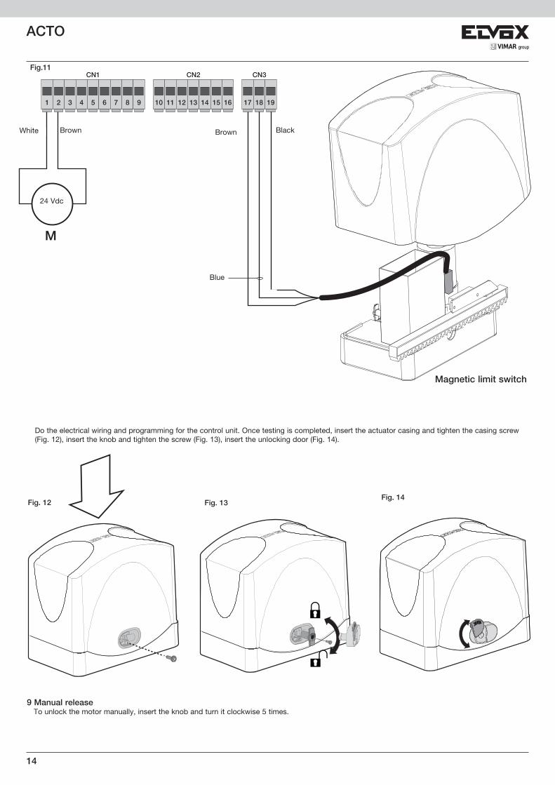
Brown White Brown Black
Blue
24 Vdc
Magnetic limit switch
Fig.11
9 Manual release To unlock the motor manually, insert the knob and turn it clockwise 5 times.
Fig. 12 Fig. 13Fig. 14
Do the electrical wiring and programming for the control unit. Once testing is completed, insert the actuator casing and tighten the casing screw (Fig. 12), insert the knob and tighten the screw (Fig. 13), insert the unlocking door (Fig. 14).
M

15VIMAR group
ACTO
EC DECLARATION OF CONFORMITY(Declaration of incorporation of partly completed machinery Annex IIB Directive 2006/42/EC)
No.: ZDT00432.00
The undersigned, representing the following manufacturer
Elvox SpAVia Pontarola, 14/A - 35011 Campodarsego
(PD) Italy
herewith declares that the products
ACTUATORS FOR SLIDING GATES - ACTO SERIES
Articles ESM1 (ACTO 400D), ESM2 (ACTO 600D)
are in conformity with the provisions of the following EU Directive(s) (including all applicable amendments) and that all of the following standards and/or specifications have been applied
LV Directive 2006/95/EC: EN 60335-2-103 (2003) + A11 (2009)EMC Directive 2004/108/EC: EN 61000-6-1 (2007), EN 61000-6-3 (2007) + A1 (2011)R&TTE Directive 1999/5/EC: EN 301 489-3 (2002), EN 300 220-3 (2000)Machinery Directive 2006/42/EC EN 13241 (2003) + A1 (2011), EN 12453 (2000)
He also declares that the product must not be commissioned until the end machine, in which it is to be incorporated, has been declared in conformity, when applicable, with the provisions of Directive 2006/42/EC.
He declares that the relevant technical documentation has been constituted by Elvox SpA, drawn up in accordance with Annex VIIB of Directive 2006/42/EC and that the following essential requirements have been fulfilled: 1.1.1, 1.1.2, 1.1.3, 1.1.5, 1.1.6, 1.2.1, 1.2.2, 1.2.6, 1.3.1, 1.3.2, 1.3.3, 1.3.4, 1.3.7, 1.3.8, 1.3.9, 1.4.1, 1.4.2, 1.5.1, 1.5.2, 1.5.4, 1.5.5, 1.5.6, 1.5.7, 1.5.8, 1.5.9, 1.6.1., 1.6.2, 1.7.1, 1.7.2, 1.7.3, 1.7.4.
He undertakes, in response to an adequately justified request from the national authorities, to present all the necessary supporting documentation concerning the product.
Campodarsego, 29/04/2013
The Chief Executive Officer
Note: The contents of this declaration match what was declared in the latest revision of the official declaration that was available before this manual was printed. This text has been adapted for editorial purposes. A copy of the original declaration can be required to Elvox SpA

16
ACTO

17VIMAR group
ACTO

Viale Vicenza, 1436063 Marostica VI - Italy
www.vimar.com49401098A0 01 1707