Embed Size (px)
Citation preview
ESO Call for Proposals – P91 Proposal Deadline: 27 September 2012, 12:00 noon CEST

*
Call for Proposals
ESO Period 91
Proposal Deadline: 27 September 2012,12:00 noon Central European Summer Time
Issued 30 August 2012
*Preparation of the ESO Call for Proposals is the responsibility of the ESO Observing ProgrammesOffice (OPO). For questions regarding preparation and submission of proposals to ESO telescopes,please contact the ESO Observing Programmes Office, [email protected].
The ESO Call for Proposals document is a fully linked pdf file with bookmarks that can be viewedwith Adobe Acrobat Reader 4.0 or higher. Internal document links appear in red and externallinks appear in blue. Links are clickable and will navigate the reader through the document (internallinks) or will open a web browser (external links).
ESO Call for Proposals Editor: Gaitee A.J. Hussain
Approved:Tim de Zeeuw
Director General
v
Contents
I Phase 1 Instructions 1
1 ESO Proposals Invited 11.1 Important recent changes (since Periods 89 and 90) . . . . . . . . . . . . . . . . . . . 21.2 Important reminders . . . . . . . . . . . . . . . . . . . . . . . . . . . . . . . . . . . . 51.3 Foreseen changes in the upcoming Periods . . . . . . . . . . . . . . . . . . . . . . . . 8
2 Getting Started 82.1 Distribution of telescope demand . . . . . . . . . . . . . . . . . . . . . . . . . . . . . 9
2.1.1 Distribution of requested Right Ascension . . . . . . . . . . . . . . . . . . . . 92.1.2 Prediction of RA demand during Period 91 . . . . . . . . . . . . . . . . . . . 11
2.2 Exposure Time Calculators . . . . . . . . . . . . . . . . . . . . . . . . . . . . . . . . 112.3 Online Data Products: Public Surveys, Science Verification, Advanced Data Products 12
3 How to submit an ESO Phase 1 proposal 133.1 How to obtain the ESOFORM Proposal Package . . . . . . . . . . . . . . . . . . . . 133.2 The ESOFORM Proposal Form . . . . . . . . . . . . . . . . . . . . . . . . . . . . . . 13
3.2.1 Important recent changes to ESOFORM . . . . . . . . . . . . . . . . . . . . . 133.2.2 Observing conditions: definitions . . . . . . . . . . . . . . . . . . . . . . . . . 13
3.3 Proposal Submission . . . . . . . . . . . . . . . . . . . . . . . . . . . . . . . . . . . . 14
II ESO Telescopes and their Instrumentation 16
4 The Observatory 164.1 La Silla . . . . . . . . . . . . . . . . . . . . . . . . . . . . . . . . . . . . . . . . . . . 164.2 Paranal . . . . . . . . . . . . . . . . . . . . . . . . . . . . . . . . . . . . . . . . . . . 17
4.2.1 The VLT Unit Telescopes (UTs) . . . . . . . . . . . . . . . . . . . . . . . . . 184.2.2 UTs Performance . . . . . . . . . . . . . . . . . . . . . . . . . . . . . . . . . . 184.2.3 Laser Guide Star facility on UT4 . . . . . . . . . . . . . . . . . . . . . . . . . 184.2.4 The ATs (VLTI only) . . . . . . . . . . . . . . . . . . . . . . . . . . . . . . . 194.2.5 VISTA . . . . . . . . . . . . . . . . . . . . . . . . . . . . . . . . . . . . . . . . 194.2.6 VST . . . . . . . . . . . . . . . . . . . . . . . . . . . . . . . . . . . . . . . . . 194.2.7 Paranal meteorological conditions . . . . . . . . . . . . . . . . . . . . . . . . . 20
4.3 Chajnantor . . . . . . . . . . . . . . . . . . . . . . . . . . . . . . . . . . . . . . . . . 20
5 Scientific Instruments: La Silla 215.1 SofI — Son of ISAAC, on the NTT . . . . . . . . . . . . . . . . . . . . . . . . . . . . 21
5.1.1 ESO Public Spectroscopic Surveys . . . . . . . . . . . . . . . . . . . . . . . . 225.2 EFOSC2 — ESO Faint Object Spectrograph and Camera 2, on the NTT . . . . . . 22
5.2.1 ESO Public Spectroscopic Surveys . . . . . . . . . . . . . . . . . . . . . . . . 235.3 HARPS — High Accuracy Radial velocity Planetary Search, on the 3.6-m . . . . . . 235.4 FEROS — Fibre-fed Extended Range Optical Spectrograph, on the 2.2-m . . . . . . 245.5 WFI — Wide Field Imager, on the 2.2-m . . . . . . . . . . . . . . . . . . . . . . . . 24
6 Scientific Instruments: Paranal 256.1 CRIRES, Cryogenic high-resolution IR Echelle Spectrograph . . . . . . . . . . . . . 25
6.1.1 Calibration . . . . . . . . . . . . . . . . . . . . . . . . . . . . . . . . . . . . . 266.1.2 Sensitivity . . . . . . . . . . . . . . . . . . . . . . . . . . . . . . . . . . . . . . 26
6.2 FORS2, Focal Reducer/low dispersion Spectrograph 2 . . . . . . . . . . . . . . . . . 266.2.1 Multi-object Spectroscopy . . . . . . . . . . . . . . . . . . . . . . . . . . . . . 276.2.2 High throughput filters . . . . . . . . . . . . . . . . . . . . . . . . . . . . . . 276.2.3 Volume-phased holographic grisms . . . . . . . . . . . . . . . . . . . . . . . . 276.2.4 Polarimetry . . . . . . . . . . . . . . . . . . . . . . . . . . . . . . . . . . . . . 276.2.5 Imaging modes and performance summary . . . . . . . . . . . . . . . . . . . . 276.2.6 FORS Instrumental Mask Simulator (FIMS) . . . . . . . . . . . . . . . . . . 28
vi
6.2.7 Accurate Astrometry or Pre-imaging Required . . . . . . . . . . . . . . . . . 286.3 FLAMES, Fibre Large Array Multi-Element Spectrograph . . . . . . . . . . . . . . . 29
6.3.1 Instrument Capabilities . . . . . . . . . . . . . . . . . . . . . . . . . . . . . . 296.3.2 Observational Requirements . . . . . . . . . . . . . . . . . . . . . . . . . . . . 306.3.3 Calibration . . . . . . . . . . . . . . . . . . . . . . . . . . . . . . . . . . . . . 316.3.4 ESO Public Spectroscopic Surveys . . . . . . . . . . . . . . . . . . . . . . . . 31
6.4 UVES, Ultraviolet and Visual Echelle Spectrograph . . . . . . . . . . . . . . . . . . 316.5 XSHOOTER: multi band, medium resolution echelle spectrograph . . . . . . . . . . 326.6 VIMOS, VIsible Multi-Object Spectrograph . . . . . . . . . . . . . . . . . . . . . . . 33
6.6.1 VIMOS Observation Requirements: IMG . . . . . . . . . . . . . . . . . . . . 356.6.2 VIMOS observation requirements: MOS and pre-imaging . . . . . . . . . . . 356.6.3 MOS Observations in Visitor Mode . . . . . . . . . . . . . . . . . . . . . . . . 356.6.4 VIMOS Observation Requirements in IFU Mode . . . . . . . . . . . . . . . . 36
6.7 VISIR, VLT Imager and Spectrometer for mid Infra Red . . . . . . . . . . . . . . . . 366.7.1 Imaging Modes . . . . . . . . . . . . . . . . . . . . . . . . . . . . . . . . . . . 366.7.2 Spectroscopy Modes . . . . . . . . . . . . . . . . . . . . . . . . . . . . . . . . 366.7.3 Calibrations . . . . . . . . . . . . . . . . . . . . . . . . . . . . . . . . . . . . . 376.7.4 Exposure Time Calculator . . . . . . . . . . . . . . . . . . . . . . . . . . . . . 37
6.8 HAWK-I, High Acuity Wide-field K-band Imager . . . . . . . . . . . . . . . . . . . . 376.8.1 Filters and field of view . . . . . . . . . . . . . . . . . . . . . . . . . . . . . . 386.8.2 Observing modes . . . . . . . . . . . . . . . . . . . . . . . . . . . . . . . . . . 386.8.3 Brightness limit and persistence . . . . . . . . . . . . . . . . . . . . . . . . . 386.8.4 Limiting magnitudes . . . . . . . . . . . . . . . . . . . . . . . . . . . . . . . . 38
6.9 NACO (NAOS+CONICA) . . . . . . . . . . . . . . . . . . . . . . . . . . . . . . . . . 396.9.1 Adaptive optics correction with Natural and Laser Guide Stars . . . . . . . . 396.9.2 Offered modes . . . . . . . . . . . . . . . . . . . . . . . . . . . . . . . . . . . 396.9.3 NACO Calibration plan and special calibrations . . . . . . . . . . . . . . . . 42
6.10 SINFONI, Spectrograph for INtegral Field Observations in the Near-Infrared . . . . 426.10.1 Instrument Performance . . . . . . . . . . . . . . . . . . . . . . . . . . . . . . 436.10.2 Brightness Limits . . . . . . . . . . . . . . . . . . . . . . . . . . . . . . . . . . 436.10.3 Sky Subtraction . . . . . . . . . . . . . . . . . . . . . . . . . . . . . . . . . . 446.10.4 Calibrations . . . . . . . . . . . . . . . . . . . . . . . . . . . . . . . . . . . . . 446.10.5 Modes that are not offered . . . . . . . . . . . . . . . . . . . . . . . . . . . . 44
6.11 MIDI, MID-infrared Interferometric instrument . . . . . . . . . . . . . . . . . . . . 446.12 AMBER, Astronomical Multi-BEam combineR . . . . . . . . . . . . . . . . . . . . . 46
6.12.1 Spectral Modes and Coverage . . . . . . . . . . . . . . . . . . . . . . . . . . . 466.12.2 Integration times, DIT . . . . . . . . . . . . . . . . . . . . . . . . . . . . . . . 466.12.3 Limiting magnitudes . . . . . . . . . . . . . . . . . . . . . . . . . . . . . . . . 466.12.4 Calibration strategies . . . . . . . . . . . . . . . . . . . . . . . . . . . . . . . 476.12.5 Execution times . . . . . . . . . . . . . . . . . . . . . . . . . . . . . . . . . . 47
6.13 VIRCAM, VISTA InfraRed CAMera . . . . . . . . . . . . . . . . . . . . . . . . . . . 476.13.1 Filters . . . . . . . . . . . . . . . . . . . . . . . . . . . . . . . . . . . . . . . . 486.13.2 Focal plane geometry . . . . . . . . . . . . . . . . . . . . . . . . . . . . . . . 486.13.3 Instrument performance . . . . . . . . . . . . . . . . . . . . . . . . . . . . . . 496.13.4 VISTA Public Surveys and Open Time Proposals . . . . . . . . . . . . . . . . 496.13.5 VIRCAM calibration plan . . . . . . . . . . . . . . . . . . . . . . . . . . . . 49
6.14 OmegaCAM . . . . . . . . . . . . . . . . . . . . . . . . . . . . . . . . . . . . . . . . . 49
7 Scientific Instruments: Chajnantor 507.1 SHFI . . . . . . . . . . . . . . . . . . . . . . . . . . . . . . . . . . . . . . . . . . . . . 507.2 LABOCA, the Large APEX Bolometer Camera . . . . . . . . . . . . . . . . . . . . . 517.3 SABOCA, the Submillimetre APEX Bolometer Camera . . . . . . . . . . . . . . . . 527.4 FLASH heterodyne receiver (MPIfR PI instrument) . . . . . . . . . . . . . . . . . . 527.5 CHAMP+: The Carbon Heterodyne Array of the MPIfR . . . . . . . . . . . . . . . 537.6 Z-Spec: The broadband millimeter-wave spectrometer . . . . . . . . . . . . . . . . . 53
8 Visitor Instruments 54
9 How to estimate overheads 54
vii
10 Calibration Plans and Pipelines 5810.1 Data Quality Control . . . . . . . . . . . . . . . . . . . . . . . . . . . . . . . . . . . . 5810.2 Calibration Plans and Calibration of Science Observations . . . . . . . . . . . . . . . 5810.3 Data Reduction Pipelines . . . . . . . . . . . . . . . . . . . . . . . . . . . . . . . . . 59
10.3.1 Data Organization: Gasgano and SAFT . . . . . . . . . . . . . . . . . . . . . 5910.3.2 Pipelines in the ESO Environment . . . . . . . . . . . . . . . . . . . . . . . . 59
10.4 Quality Control . . . . . . . . . . . . . . . . . . . . . . . . . . . . . . . . . . . . . . . 6010.5 The ESO Science Data Products Forum . . . . . . . . . . . . . . . . . . . . . . . . . 60
III Proposal Types, Policies, and Procedures 61
11 Proposal Types 6111.1 Normal Programmes . . . . . . . . . . . . . . . . . . . . . . . . . . . . . . . . . . . . 6111.2 Large Programmes . . . . . . . . . . . . . . . . . . . . . . . . . . . . . . . . . . . . . 6211.3 Target of Opportunity . . . . . . . . . . . . . . . . . . . . . . . . . . . . . . . . . . . 62
11.3.1 Rapid Response Mode (RRM) . . . . . . . . . . . . . . . . . . . . . . . . . . 6311.4 Guaranteed Time Observations . . . . . . . . . . . . . . . . . . . . . . . . . . . . . . 6411.5 Proposals for Calibration Programmes . . . . . . . . . . . . . . . . . . . . . . . . . . 6511.6 Director’s Discretionary Time . . . . . . . . . . . . . . . . . . . . . . . . . . . . . . . 6511.7 Host State Proposals . . . . . . . . . . . . . . . . . . . . . . . . . . . . . . . . . . . . 6611.8 Non-Member State Proposals . . . . . . . . . . . . . . . . . . . . . . . . . . . . . . . 6611.9 VLT-XMM proposals . . . . . . . . . . . . . . . . . . . . . . . . . . . . . . . . . . . . 66
12 Observing Modes 6712.1 Visitor Mode . . . . . . . . . . . . . . . . . . . . . . . . . . . . . . . . . . . . . . . . 67
12.1.1 ToO programme execution during VM observations . . . . . . . . . . . . . . . 6812.2 Service Mode . . . . . . . . . . . . . . . . . . . . . . . . . . . . . . . . . . . . . . . . 68
12.2.1 Service Mode policies . . . . . . . . . . . . . . . . . . . . . . . . . . . . . . . 68
13 Policy Summary 7013.1 Who may submit, time allocation policies . . . . . . . . . . . . . . . . . . . . . . . . 7013.2 Requesting use of non-standard observing configurations . . . . . . . . . . . . . . . . 7013.3 Policy regarding offered/available observing configurations . . . . . . . . . . . . . . . 7113.4 Observing programme execution . . . . . . . . . . . . . . . . . . . . . . . . . . . . . 71
13.4.1 Service Mode run execution . . . . . . . . . . . . . . . . . . . . . . . . . . . . 7113.5 Phase 2 Service Mode policy: constraints and targets are binding . . . . . . . . . . . 7113.6 Pre-imaging runs . . . . . . . . . . . . . . . . . . . . . . . . . . . . . . . . . . . . . . 7213.7 Data rights, archiving, data distribution . . . . . . . . . . . . . . . . . . . . . . . . . 7213.8 Publication of ESO telescope results . . . . . . . . . . . . . . . . . . . . . . . . . . . 7213.9 Press Releases . . . . . . . . . . . . . . . . . . . . . . . . . . . . . . . . . . . . . . . . 72
IV Appendix 73
A Acronyms 73

*

1
Part I
Phase 1 Instructions
1 ESO Proposals Invited
The European Southern Observatory (ESO) invites proposals for observations at ESO tele-scopes during Period 91 (1 April 2013 – 30 September 2013). The following instruments areoffered in this period:
La Silla
EFOSC2 (ESO Faint Object Spectrograph 2)FEROS (Fibre-fed Extended Range Optical Spectrograph)HARPS (High Accuracy Radial velocity Planetary Searcher)SofI (Son of ISAAC)WFI (Wide Field Imager)
Paranal
AMBER (Near-infrared interferometric instrument)CRIRES (Cryogenic high-resolution IR Echelle Spectrograph)FLAMES (Fibre Large Array Multi Element Spectrograph)FORS2 (FOcal Reducer/low dispersion Spectrograph 2)HAWK-I (High Acuity Wide field K-band Imager)MIDI (MID-infrared Interferometric instrument)NAOS-CONICA (High Resolution NIR Camera and Spectrograph)OmegaCAM (Wide Field Imager for the VST at Paranal)SINFONI (Spectrograph for INtegral Field Obs. in the NIr)UVES (UV–Visual Echelle Spectrograph)VIMOS (Visual Multi-Object Spectrograph)VIRCAM (VISTA InfraRed CAMera)VISIR (VLT Imager and Spectrometer for mid Infra Red)XSHOOTER (UV–Visual–NIR medium resolution echelle spectrograph)
Chajnantor
LABOCA (Large Apex BOlometer CAmera)SABOCA (Submillimetre APEX Bolometer CAmera)SHFI (Swedish Heterodyne Facility Instrument)CHAMP+ (Carbon Heterodyne Array of the MPIfR)FLASH (First Light APEX Submillimeter Heterodyne receiver)Z-Spec (Broadband millimeter wave spectrometer)
The main characteristics of all instruments offered at La Silla, Paranal and Chajnantor in this callare available in the ESO Instruments Summary Table.
The ESO proposal submission deadline is:
27 September 2012,12:00 noon Central European Summer Time.
In each submitted proposal, one single person, the Principal Investigator (PI), must be identifiedas being principally responsible for this proposal. By submitting a proposal the PI agrees that
2
he/she and his/her collaborators will act according to ESO’s policies and regulations (including theconditions specified in the present Call for Proposals) if observing time is granted.
Any question about policies or the practical aspects of proposal preparation should be addressedto the ESO Observing Programmes Office, [email protected]. Enquiries about technical requirements ofthe planned observations should be sent to the User Support Department ([email protected]) forParanal and Chajnantor and to [email protected] for La Silla. Enquiries can also be made throughthe “Ask for help” link in the User Portal, which is listed under “Other Services”.
Part I of this Call for Proposals provides information on how to complete and submit a Phase 1proposal to ESO, Part II summarises the capabilities of ESO telescopes and available instrumenta-tion, while Part III describes the policies and procedures regarding proposing for, carrying out, andpublishing ESO observations.
1.1 Important recent changes (since Periods 89 and 90)
• General changes
– ESO proposal submission deadline: Please note that the ESO deadline will bestrictly enforced. It is the PI’s responsibility to resolve any verification or upload problemsrelated to the instrument configuration, LaTeX file or associated figures well before thedeadline. ESO cannot provide support beyond 11:00 CEST on the day of the deadline.The online receiver will switch off at 12:00 CEST. No submissions or amendments tosubmitted proposals can be accepted after this time.
– PI Pack Service and Science Processing: As of October 2011, the PI Pack serviceand science processing in Garching have been discontinued. PIs and their delegates canaccess their raw science data through the ESO Science Archive Facility; this requiresauthentication through the ESO User Portal. A new archive service, the CalSelector, hasbeen deployed to automatically associate science files with the complete set of calibrationsand ancillary files needed for processing and data exploitation.
– Precipitable Water Vapour (PWV): A radiometer was successfully commissionedat Paranal in October 2010, which continuously provides a measurement of the amountof the precipitable water vapour (PWV) above the observatory. Users of CRIRES andthe APEX instruments in service mode should specify PWV as an observing constraintduring their Phase 1 and Phase 2 preparation. Examples are shown in the ESOFORMpackage template files. It is expected that VISIR users will also be able to provide PWVconstraints during their Phase 2 preparation.
– Large Programmes: As in previous periods no Large Programmes will be acceptedfor the 2.2-m, VISTA or VST telescopes. On APEX, Large Programmes will not beaccepted for the PI instruments, CHAMP+, FLASH and Z-Spec. In Period 91 LargeProgrammes are also not offered for the following VLT instruments: CRIRES, HAWK-I,NACO, VIMOS. These restrictions are due to the following reasons:
∗ CRIRES may be affected by possible future changes;
∗ HAWK-I will be affected by the installation of the AOF in 2014;
∗ NACO will likely be removed in 2013 to allow the installation of the second generationVLT instrument, MUSE;
∗ VIMOS has a significant number of existing commitments.
Large Programmes for MIDI and/or the VLTI visitor instrument must not request periodsbeyond Period 91 due to the arrival of the second generation VLTI instruments.
– ESO/GTC Large Programmes: There will be no further calls for ESO/GTC LargeProgrammes. The titles and target lists of these approved programmes are listed on thefollowing page:Targets for approved ESO/GTC Programmes.
– Guaranteed Time Observations (GTO) will be carried out in Period 91 withAMBER, MIDI, NACO, OmegaCAM, SINFONI, XSHOOTER and the VLTIVisitor Instrument. For details about the planned observations, please seehttp://www.eso.org/sci/observing/teles-alloc/gto/91.html.
3
• Paranal
– News on Paranal telescopes and instruments can be found athttp://www.eso.org/sci/facilities/lpo/news/.
– VLT-XMM proposals: Proposals are invited for scientific programmes requiring bothVLT(I) and XMM-Newton observations (Section 11.9). These proposals may be sub-mitted for the next XMM-Newton cycle, which extends over ESO Periods 91 and 92.However, proposers should take the limited availability of some of the VLT(I) instru-ments in Periods 91 and 92 into account; see below for details on instrument availability.
– VLT Visitor instruments: No Visitor Instrument focus is available on the VLT dueto the installation of KMOS during Period 90.
– UT1 – Antu:
∗ CRIRES:
· Starting from Period 90 a metrology system should ensure sub-pixel reproducibil-ity of the wavelength scale. It is possible that the calibration frequency will bedecreased due to the improved stability of the instrument.
· Users of CRIRES should specify PWV as a constraint during their Phase 1 andPhase 2 preparation.
· Large Programme proposals using CRIRES will not be accepted.
∗ FORS2 A new functionality has been added to the fast acquisition templates (includ-ing the RRM ones) for long-slit spectroscopy, spectropolarimetry, and spectropho-tometry. It is now possible to align the slit along any direction defined by two objectsand offer several centering options.
∗ KMOS will be installed on the UT1 Nasmyth B platform in November 2012. Itscommissioning runs will take place during Period 90 and 91.
– UT2 – Kueyen:
∗ XSHOOTER:
· Telluric standard stars will be observed in nodding instead of staring mode inPeriod 91. The 400 kHz readout mode for the UVB/VIS arms will be usedindependently of the readout speed used for the science observations. Detectorbinning will be the same as for the science observations. This change gives abetter correction of the telluric emission and absorption lines as well as badpixels, especially in the NIR arm. The provided S/N will be between 50-150 bydefault. Users requiring higher S/N are encouraged to submit their own telluricstar OBs, in which case the corresponding execution time must be included inthe time requested at Phase 1.There is no change for the IFU telluric standard stars observations.
· The Atmospheric Dispersion Correction (ADC) systems on the UVB/VIS armsare not reliable. Since August 1st, 2012, the ADCs have been fixed in their non-deviation position. Data obtained in this configuration can be reduced by thepipeline without significant degradation. Updates on the status of the ADCs canbe found on the XSHOOTER news webpage. The latest version of the usermanual provides plots for helping users prepare observations without ADCs.Users are recommended to carry out observations at the parallactic angle when-ever possible or to take special care on the airmass constraint to avoid flux loss.
– UT3 – Melipal:
∗ ISAAC and SPHERE: SPHERE installation is expected to take place duringPeriod 90. Commissioning runs will therefore occur during Period 90 and 91. As aconsequence ISAAC is no longer offered.
∗ VIMOS:
· A final adjustment to the focussing hardware will be done at the end of 2012.This should improve the focussing range for the IFU mode.
· The new VPH HR blue grisms have been characterized and have been in normaloperations since Period 89. See details in the VIMOS web pages.
4
· A new Pre-Image-Less MOS (PILMOS) mode will be offered starting fromPeriod 91 in which a user provided catalogue with accurate target coordinates(≤ ±0.2′′)) can be used to design masks. In the PILMOS mode the slit orienta-tion must be N-S (rotator angle 90 deg).
· Starting from Period 91 the requirement for a fixed orientation of the MOS slitalong the N-S direction is relaxed. Provided the requested target field declinationis within −45◦ < δ < −5◦, slits can also be oriented E-W (rotator angle 0 deg)and the observations executed within ±3 h from meridian. In this case a pre-imaging run must be requested.
· VIMOS is not available for Large Programmes in Period 91 due to existing com-mitments.
∗ VISIR has undergone a major upgrade during Period 89, which includes a recom-missioning and a performance validation phase. The aim of this upgrade is to opti-mize its performance and enhance its scientific output. Details are available in theVISIR web pages. VISIR users will be able to set constraints on the PWV duringtheir Phase 2 preparation.
– UT4 – Yepun:
∗ VLT Laser Guide Star
· PARSEC, the current laser used by the Laser Guide Star Facility (LGSF), willbe decommissioned during Period 90. It will be replaced by a prototype of thelaser used by the coming Adaptive Optics Facility. Its commissioning is expectedto be completed by the end of February 2013.
· The current Laser Guide Star (LGS) can be used for up to 15% of the UT4 sciencetime due to the required sky conditions and intrinsic operational constraints.Provided that the new laser is successfully commissioned, both the deliveredpower and the number of nights during which the LGSF can be used everymonth will be significantly increased. However, taking into account the existingcommitments for this facility (in particular, for ongoing Large Programmes andfor Guaranteed Time Observations), it is expected that only a limited amount oftime can be allocated in Period 91 to new programmes requiring the use of theLGS. Accordingly, proposers are encouraged to carry out a critical assessment ofthe need for LGS for execution of their observations, and to carefully study thepossibility of using a Natural Guide Star (NGS).
∗ HAWK-I:
· Large Programmes using HAWK-I will not be accepted in Period 91.
· A user provided narrow-band filter centered at 0.984µm was installed in August2012 in the slot used by the NB1190 narrow-band filter, which is therefore notoffered in P91.
∗ NACO:
· NACO will likely be removed from the UT4 Nasmyth B platform in the secondhalf of 2013 to allow for the installation of MUSE.
· Large Programmes using NACO will not be accepted.
· Since Period 90, pupil tracking mode with focal-plane coronographic masks hasbeen offered also in SM.
All programmes requiring special calibrations must request VM. Chopping is unavail-able: users should use the L′ or NB 4.05 filters without chopping instead.
– VLTI:
∗ VLTI-ATs: New baselines have been offered since Period 90 (see the VLTI baselinepage).
∗ AMBER: AMBER can be operated in self-coherencing mode which significantlyimproves the quality of data when FINITO cannot be used for fringe tracking. Thispossibility is only offered in visitor mode. Check the AMBER Users’ Manual fordetails.
5
∗ MIDI:
· Starting from Period 91 MIDI will be offered with the FSU-A as an externalfringe-tracker. FSU-A works in K-band and will be used for on-axis tracking.MIDI with the ATs will be able to attain a sensitivity similar to what is nowpossible with UTs, after data reduction using the fringe tracker data. This con-figuration is only offered in visitor mode.
· Given the arrival of the second generation VLTI instruments, ESO cannot guar-antee the availability of MIDI after Period 91.
· Large Programmes requiring the use of MIDI beyond Period 91 will not be ac-cepted.
∗ VLTI Visitor instruments:
· Given the arrival of the second generation VLTI instruments, ESO cannot guar-antee the availability of a VLTI visitor focus beyond Period 91.
· Large Programmes requiring the use of a VLTI visitor instrument beyondPeriod 91 will not be accepted.
• La Silla
– 3.6m: A significant fraction (35%) of the available science time is committed to ongoingLarge Programmes in Period 90 (see Fig. 4). Large programmes on the 3.6m telescopecan span up to seven periods, until Period 97.
– NTT: A large fraction (50%) of the available science time on the NTT telescope iscommitted to ongoing programmes (see Fig. 4). A significant fraction of the availabledark and grey conditions are committed to these programmes. Large programmes on theNTT can span up to seven periods, until Period 97.
– 2.2-m: Time is available on this telescope for proposals requesting observations to beexecuted during the slots assigned to ESO (see Section 4.1 for details). Proposers shouldtake these time slots into account for the selection of the targets of their proposals.Proposals for Large Programmes will not be accepted for this telescope.
• Chajnantor
– SHFI: The APEX-T2 receiver is offered conditional to a successful repair mission plannedin January 2013.
– CHAMP+: This MPIfR PI instrument is offered again to the ESO community incollaboration with MPIfR.
– FLASH: This MPIfR PI instrument has been upgraded to allow simultaneous observa-tions in the 272-377 GHz and 385-495 GHz bands. Limited observing time is offered tothe ESO community in collaboration with MPIfR.
– Z-Spec: This PI instrument is offered again at APEX, in collaboration with the instru-ment team.
1.2 Important reminders
• General information
– ESO User Portal: Proposals are submitted via a web upload procedure using theonline tool, Web Application for Submitting Proposals (WASP). This requires users tofirst log in to the ESO User Portal at: http://www.eso.org/UserPortal. See Section 3for more details.
– Duration of one night: Proposers are reminded that for all ESO telescopes, the dura-tion of one night is 8 hours in even periods and 10 hours in odd periods.
– Duplications: Large amounts of data are available via the ESO data archive (Section 2.3;see http://archive.eso.org). Proposers are strongly advised to check if observationsequivalent to the proposed ones have been performed already. Proposers must check thattheir planned observations are not duplicating Guaranteed Time proposals for Period 91:GTO for Period 91 or ongoing Public Survey observations.
6
– Public Spectroscopic Surveys (PSS): Two Public Spectroscopic Surveys are be-ing carried out on the NTT telescope (EFOSC2 & SOFI), and on the UT2 tele-scope using FLAMES (GIRAFFE & UVES). Further details are available on the ESOPublic Surveys Projects webpage.
– Overheads: All proposals (Service Mode or Visitor Mode) must include all overheadswhen computing the total observing time request (see Section 9).
– Access to Service and Visitor Mode data: Principal Investigators of Service andVisitor Mode programmes and their data delegates have access to their proprietary rawdata as soon as the data have been ingested in the ESO Archive. The data access is pro-vided through the ESO User Portal. The CalSelector archive service packs together thescience files with any ancillary files that are needed to process the data, (e.g. acquisitionimages, calibrations, etc.).
Please note that the 1-year proprietary period starts as soon as the data are made elec-tronically available to the PI.
– Non-standard observing configurations: The use of non-standard instrumentalmodes, configurations or filters requires the prior approval by the ESO User SupportDepartment. A detailed justification should be sent to [email protected] at least twoweeks before the proposal submission deadline (also see 13.2).
– Backup programme: Although Phase 1 proposals requesting Visitor Mode do not needto include backup targets and/or a backup programme, the observer should prepare onein case of unfavourable weather conditions (see Section 4.2.7). The original science goalsmust be adhered to in this backup scenario. Approval of a backup programme must besought at least one month in advance through the change request form as described inSection 12.1.
– The information provided in the proposal is binding: all observing runs must be executedas described in the proposal. Deviations from the proposal (either by observing differenttargets or by using different instrument modes or different constraints) may be allowedonly under exceptional circumstances and after approval by ESO (see Section 13.5).
• Paranal
– Observing mode on the VLT: Departures from the observing mode requested by theproposers may be implemented by ESO so as to achieve a balanced distribution betweenService Mode and Visitor Mode.
As a rule, proposers should request Service Mode only for observations that demonstrablybenefit from the short-term scheduling flexibility allowed by this mode. Proposers mayidentify runs that lend themselves for observations in either Service or Visitor Mode byspecifying one of the modes using the alternative run feature in Box 3 of the ESOFORMPhase 1 proposal form. Please note that if a certain instrument mode is offered exclusivelyin either Service Mode or Visitor Mode then this overrides these scheduling considerations.
– Service Mode OBs: Service Mode Observation Blocks (OBs) including all overheadscan last up to a maximum of 1 hour. Longer OBs have to be specifically requested andjustified at Phase 2 via a waiver request, which is evaluated by the Observatory.
– Pre-imaging for VLT instruments and modes: A separate pre-imaging runmust be specified in the proposal (to be executed in Service Mode). Failure to do so willresult in the deduction of the time necessary for the pre-imaging from the allocation tothe main part of the project (see Section 13.6).
– Monitoring in Service Mode: Monitoring a target in Service Mode is carried out ona best effort basis only, i.e. a monitoring sequence may be interrupted by long periods ofunsuitable weather conditions or Visitor Mode scheduling. All the time needed to observeone target should be included in one single run; these can be split into the single epochobservations using a time-linked series in version 3 of the Phase 2 Preparation Tool(P2PP) (see Section 12.2.1 for more information).
– Rapid Response Mode (RRM): FORS2, UVES, XSHOOTER, SINFONI and HAWK-I continue to be offered in this mode in Period 91. RRM observations that correspondto events with exceptional characteristics may be activated during either Service Mode

7
or Visitor Mode runs, over which they have observational priority (except if the serviceor visitor mode runs involve strictly time-critical observations). For details on the RRMpolicies, see Section 11.3.1.
– VISTA: Due to ongoing Public Surveys only a limited amount of open time is availableon VISTA; these observations are carried out in Service Mode only and for restrictedRight Ascension ranges. Open time proposals should clearly justify the scientific goalsand why they are not achievable through the scheduled public survey observations. Onlythose proposals that have complementary constraints and coordinate ranges with respectto public survey observations may be scheduled, as the highest priority is given to advancepublic surveys on VISTA.
• La Silla
– Support during observing runs and transportation schedule: A streamlinedoperation is in effect in La Silla. Technical and logistical support will be delivered asusual by ESO staff, but no specific support astronomer is assigned. Please note thatthe transportation schedule to and from La Silla may have an impact on the arrival anddeparture days of the observers at the site. See Section 4.1 for additional details andcheck the online instructions for visiting astronomers.
– Large Programmes on NTT and the 3.6-m telescopes may have a duration of up to fouryears.
– There is a minimum length of 3 nights for runs to be executed with La Silla tele-scopes. Proposals including La Silla runs with a duration of less than 3 nights willbe rejected at submission time by the automatic proposal reception system, with threeexceptions:
1. There is no minimum duration for runs to be carried out with Visitor Instruments(see Section 8). However, in order to minimise the overheads associated with theirinstallation and removal, such instruments are normally scheduled in blocks includingseveral contiguous runs; the length of these combined blocks is typically greater than3 nights.
2. On the NTT, users can apply for combined runs using both EFOSC2 and SOFI. Thetotal duration of each of these runs must be at least three nights. The combined runsmust be requested using the instrument name “SOFOSC”. Details are also availablein Section 3.2.1 and the ESOFORM User Manual.
3. There is no minimum duration for runs of Calibration Programmes.
Note that the minimum duration requirement for La Silla is applicable to each individualrun of a proposal involving a La Silla instrument (see Section 11 for more informationabout the definition of “programme” and “run”). More generally, proposals for long runsare strongly encouraged on the La Silla telescopes. Splitting of runs in half nights (e.g.a 3-night run spread over 6 half nights) should be avoided as much as possible; such runsmay be impossible to schedule.
– Pre-imaging: Pre-imaging frames for EFOSC2 will have to be obtained at the beginningof the spectroscopic run. The resulting lower efficiency should be taken into account inthe computation of the execution time required for such runs.
• Chajnantor
– APEX: This telescope is offered in Service Mode only. APEX users should ensure thattheir proposal meets the following requirements:
∗ specify if time is requested from other APEX partners in the macro, \SpecialRemarks(Box 5);
∗ specify the requested PWV using the macro, \Target (Box 11), for their project toallow a better distinction between observations requesting a range of atmospherictransparencies;
∗ either indicate an appropriate off-source position or request time to find such a po-sition if they wish to observe extended line-emitting regions;

8
∗ merge all observations for any APEX instrument into a single run (note that this alsoapplies for the different receivers of SHFI). For Large Programmes this restrictionshould be understood as a single run per instrument and per period. Separate runsshould be specified for observations in different periods.
1.3 Foreseen changes in the upcoming Periods
• Monitoring Programmes: The OPC Working Group and the ESO Users Committee haverecommended the introduction of Monitoring Programme proposals. These proposals willenable users to request a limited amount of time to monitor targets over more than oneperiod. The Observing Programmes Office is actively working towards implementing this newprogramme type by Period 93.
• 2nd Generation VLT Instruments:
– The commissioning of KMOS and SPHERE will continue in Period 92.
– The installation of MUSE on UT4 is planned for Period 92.
• UT4 – Yepun:
– UT4 will not be available during part of Period 92 to allow for the installation of theDeformable Secondary Mirror and re-commissioning of the telescope.
– The Laser Guide Star Facility (LGSF) is expected to be decommissioned at the endof Period 92 to allow for the installation of the Deformable Secondary Mirror (part of theAOF).
– NACO is expected to be removed from the UT4 Nasmyth B platform during 2013 toallow the installation of the second generation instrument, MUSE.
• VIMOS: A call for public spectroscopic surveys may be issued for VIMOS in the near future,if the instrument upgrade is successful and the observation backlog has been resolved.
• MIDI: Given the arrival of the second generation VLTI instruments, ESO cannot guaran-tee the availability of MIDI beyond Period 91. Proposals for Large Programme using thisinstrument beyond Period 91 will therefore not be accepted.
• ZEUS-2: Pending successful commissioning, the redshift (z) and Early Universe Spectrometer(ZEUS-2) may be offered as a PI instrument during Period 92. ZEUS-2 is a broad-band spectrograph covering 7 telluric windows covering 200 to 850µm. For details, seeFerkinhoff et al. 2010.
2 Getting Started
Observing proposals must contain a scientific case, a summary of the proposed observing programme,a list of desired instrument modes and configurations, a target list, and a precise definition of requiredobserving conditions (seeing, atmospheric transparency, lunar illumination, etc.). In addition, acalculation of the number of hours/nights of observing time needed to accomplish the scientificgoals must be carried out and summarized in the proposal. It is therefore important that proposersconsult technical documentation or instrument experts regarding the instrument capabilities andsensitivities. Section 9 provides more details on how calculate overheads with different instrumentsetups using the Phase 2 Preparation Tool (P2PP).
The following sections give some additional information and references that should be useful toproposers.
9
0.0
1.0
2.0
3.0
4.0
5.0
6.0
7.0
83 84 85 86 87 88 89 90
Telescop
e Pressure
Period
UT1
UT2
UT3
UT4
2.2
3.6
NTT
VLTI
APEX
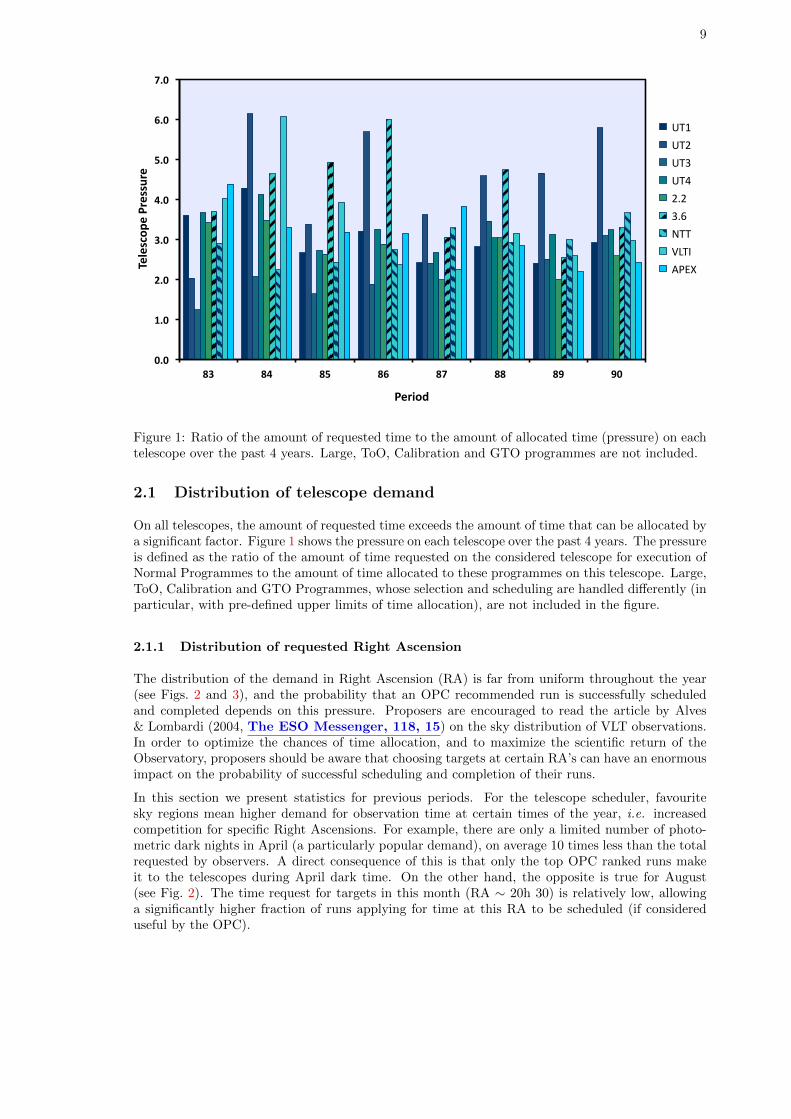
Figure 1: Ratio of the amount of requested time to the amount of allocated time (pressure) on eachtelescope over the past 4 years. Large, ToO, Calibration and GTO programmes are not included.
2.1 Distribution of telescope demand
On all telescopes, the amount of requested time exceeds the amount of time that can be allocated bya significant factor. Figure 1 shows the pressure on each telescope over the past 4 years. The pressureis defined as the ratio of the amount of time requested on the considered telescope for execution ofNormal Programmes to the amount of time allocated to these programmes on this telescope. Large,ToO, Calibration and GTO Programmes, whose selection and scheduling are handled differently (inparticular, with pre-defined upper limits of time allocation), are not included in the figure.
2.1.1 Distribution of requested Right Ascension
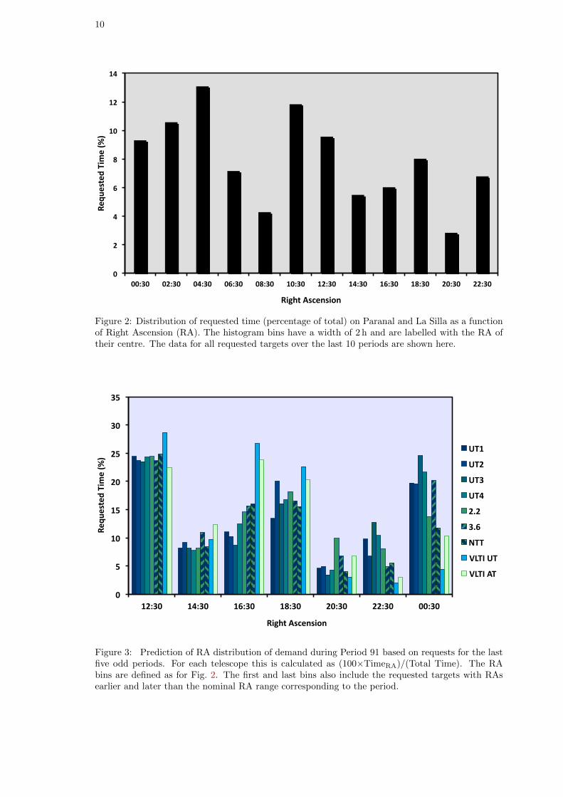
The distribution of the demand in Right Ascension (RA) is far from uniform throughout the year(see Figs. 2 and 3), and the probability that an OPC recommended run is successfully scheduledand completed depends on this pressure. Proposers are encouraged to read the article by Alves& Lombardi (2004, The ESO Messenger, 118, 15) on the sky distribution of VLT observations.In order to optimize the chances of time allocation, and to maximize the scientific return of theObservatory, proposers should be aware that choosing targets at certain RA’s can have an enormousimpact on the probability of successful scheduling and completion of their runs.
In this section we present statistics for previous periods. For the telescope scheduler, favouritesky regions mean higher demand for observation time at certain times of the year, i.e. increasedcompetition for specific Right Ascensions. For example, there are only a limited number of photo-metric dark nights in April (a particularly popular demand), on average 10 times less than the totalrequested by observers. A direct consequence of this is that only the top OPC ranked runs makeit to the telescopes during April dark time. On the other hand, the opposite is true for August(see Fig. 2). The time request for targets in this month (RA ∼ 20h 30) is relatively low, allowinga significantly higher fraction of runs applying for time at this RA to be scheduled (if considereduseful by the OPC).
10
0
2
4
6
8
10
12
14
00:30 02:30 04:30 06:30 08:30 10:30 12:30 14:30 16:30 18:30 20:30 22:30
Requ
ested Time (%
)
Right Ascension
Figure 2: Distribution of requested time (percentage of total) on Paranal and La Silla as a functionof Right Ascension (RA). The histogram bins have a width of 2 h and are labelled with the RA oftheir centre. The data for all requested targets over the last 10 periods are shown here.
0
5
10
15
20
25
30
35
12:30 14:30 16:30 18:30 20:30 22:30 00:30
Requ
ested Time (%
)
Right Ascension
UT1
UT2
UT3
UT4
2.2
3.6
NTT
VLTI UT
VLTI AT
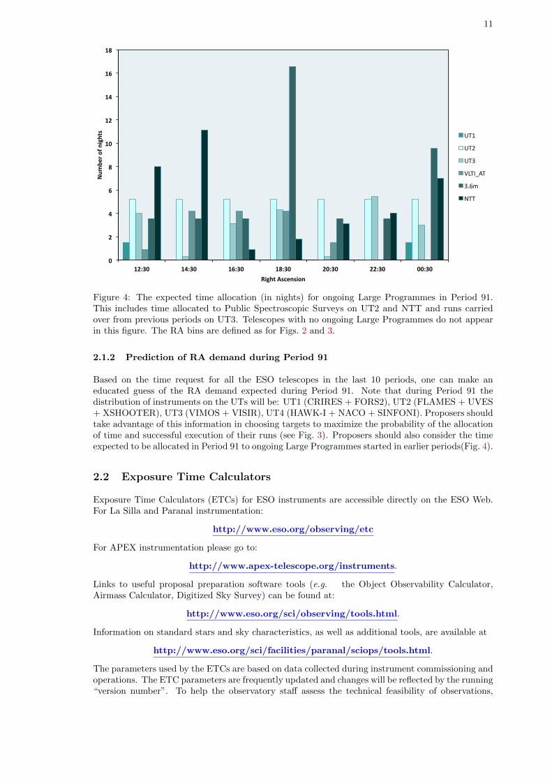
Figure 3: Prediction of RA distribution of demand during Period 91 based on requests for the lastfive odd periods. For each telescope this is calculated as (100×TimeRA)/(Total Time). The RAbins are defined as for Fig. 2. The first and last bins also include the requested targets with RAsearlier and later than the nominal RA range corresponding to the period.
11
0
2
4
6
8
10
12
14
16
18
12:30 14:30 16:30 18:30 20:30 22:30 00:30
Num
ber of nights
Right Ascension
UT1
UT2
UT3
VLTI_AT
3.6m
NTT
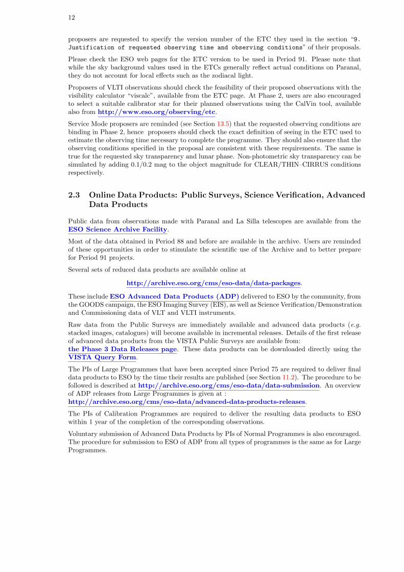
Figure 4: The expected time allocation (in nights) for ongoing Large Programmes in Period 91.This includes time allocated to Public Spectroscopic Surveys on UT2 and NTT and runs carriedover from previous periods on UT3. Telescopes with no ongoing Large Programmes do not appearin this figure. The RA bins are defined as for Figs. 2 and 3.
2.1.2 Prediction of RA demand during Period 91
Based on the time request for all the ESO telescopes in the last 10 periods, one can make aneducated guess of the RA demand expected during Period 91. Note that during Period 91 thedistribution of instruments on the UTs will be: UT1 (CRIRES + FORS2), UT2 (FLAMES + UVES+ XSHOOTER), UT3 (VIMOS + VISIR), UT4 (HAWK-I + NACO + SINFONI). Proposers shouldtake advantage of this information in choosing targets to maximize the probability of the allocationof time and successful execution of their runs (see Fig. 3). Proposers should also consider the timeexpected to be allocated in Period 91 to ongoing Large Programmes started in earlier periods(Fig. 4).
2.2 Exposure Time Calculators
Exposure Time Calculators (ETCs) for ESO instruments are accessible directly on the ESO Web.For La Silla and Paranal instrumentation:
http://www.eso.org/observing/etc
For APEX instrumentation please go to:
http://www.apex-telescope.org/instruments.
Links to useful proposal preparation software tools (e.g. the Object Observability Calculator,Airmass Calculator, Digitized Sky Survey) can be found at:
http://www.eso.org/sci/observing/tools.html.
Information on standard stars and sky characteristics, as well as additional tools, are available at
http://www.eso.org/sci/facilities/paranal/sciops/tools.html.
The parameters used by the ETCs are based on data collected during instrument commissioning andoperations. The ETC parameters are frequently updated and changes will be reflected by the running“version number”. To help the observatory staff assess the technical feasibility of observations,
12
proposers are requested to specify the version number of the ETC they used in the section “9.Justification of requested observing time and observing conditions” of their proposals.
Please check the ESO web pages for the ETC version to be used in Period 91. Please note thatwhile the sky background values used in the ETCs generally reflect actual conditions on Paranal,they do not account for local effects such as the zodiacal light.
Proposers of VLTI observations should check the feasibility of their proposed observations with thevisibility calculator “viscalc”, available from the ETC page. At Phase 2, users are also encouragedto select a suitable calibrator star for their planned observations using the CalVin tool, availablealso from http://www.eso.org/observing/etc.
Service Mode proposers are reminded (see Section 13.5) that the requested observing conditions arebinding in Phase 2, hence proposers should check the exact definition of seeing in the ETC used toestimate the observing time necessary to complete the programme. They should also ensure that theobserving conditions specified in the proposal are consistent with these requirements. The same istrue for the requested sky transparency and lunar phase. Non-photometric sky transparency can besimulated by adding 0.1/0.2 mag to the object magnitude for CLEAR/THIN–CIRRUS conditionsrespectively.
2.3 Online Data Products: Public Surveys, Science Verification, AdvancedData Products
Public data from observations made with Paranal and La Silla telescopes are available from theESO Science Archive Facility.
Most of the data obtained in Period 88 and before are available in the archive. Users are remindedof these opportunities in order to stimulate the scientific use of the Archive and to better preparefor Period 91 projects.
Several sets of reduced data products are available online at
http://archive.eso.org/cms/eso-data/data-packages.
These include ESO Advanced Data Products (ADP) delivered to ESO by the community, fromthe GOODS campaign, the ESO Imaging Survey (EIS), as well as Science Verification/Demonstrationand Commissioning data of VLT and VLTI instruments.
Raw data from the Public Surveys are immediately available and advanced data products (e.g.stacked images, catalogues) will become available in incremental releases. Details of the first releaseof advanced data products from the VISTA Public Surveys are available from:the Phase 3 Data Releases page. These data products can be downloaded directly using theVISTA Query Form.
The PIs of Large Programmes that have been accepted since Period 75 are required to deliver finaldata products to ESO by the time their results are published (see Section 11.2). The procedure to befollowed is described at http://archive.eso.org/cms/eso-data/data-submission. An overviewof ADP releases from Large Programmes is given at :http://archive.eso.org/cms/eso-data/advanced-data-products-releases.
The PIs of Calibration Programmes are required to deliver the resulting data products to ESOwithin 1 year of the completion of the corresponding observations.
Voluntary submission of Advanced Data Products by PIs of Normal Programmes is also encouraged.The procedure for submission to ESO of ADP from all types of programmes is the same as for LargeProgrammes.
13
3 How to submit an ESO Phase 1 proposal
3.1 How to obtain the ESOFORM Proposal Package
The ESOFORM Proposal Package for this period may be obtained by logging into the ESO UserPortal. Please follow the instructions at:
http://www.eso.org/sci/observing/phase1/esoform.html
3.2 The ESOFORM Proposal Form
The “ESOFORM User Manual” describes in detail how to fill the LATEX template, and the informa-tion required to prepare a valid proposal. Please be aware that the ESOFORM package is regularlyupdated. Proposers should only use the Period 91 package to prepare their proposals.
The telescope schedules are prepared using scheduling software that relies on accurate constraints(see Alves 2005, The ESO Messenger, 119, 20). Hence, scheduling constraints that are notindicated or are inaccurately specified in BOX 13 of ESOFORM are unlikely to be taken into accountby the scheduler. Retrofitting scheduling constraints after the release of the schedule isnot possible.
3.2.1 Important recent changes to ESOFORM
• ESO proposal submission deadline: Please note that the ESO deadline will be strictlyenforced: users should plan accordingly. It is the PI’s responsibility to resolve any verificationor upload problems related to the instrument configuration, LaTeX file or associated figures.The online receiver will switch off at 12:00 CEST on the day of the deadline; ESO cannot pro-vide support with problem proposal submissions after 11:00 CEST. Requests for submissionsor amendments after the deadline will not be considered.
• Precipitable water vapour (PWV) constraints: PWV constraints must be specified forCRIRES and all APEX instruments in the “Additional Notes” column of the Target macro.Please see the ESOFORM User Manual for more details.
• PhD thesis information: The \Thesis macro (Box 7) has been removed from the Normalproposal template form in order to allow more space for “Special remarks”.
• VLT-XMM Proposals: Proposers must indicate in the ESOFORM if they are applying forVLT-XMM time under the ESA-ESO agreement (see Section 11.9). VLT-XMM proposals mayinclude observing runs to be executed in Period 91 and/or in P92.
If the proposal is a re-submission of an old proposal then OPC comments must be addressedin this new submission.
3.2.2 Observing conditions: definitions
Observing conditions are defined as follows:
• Sky Transparency
– Photometric: No visible clouds, transparency variations under 2%, only assessable by theanalysis of photometric standard stars.
– Clear: Less than 10% of the sky (above 30 degrees elevation) covered in clouds, trans-parency variations under 10%.
– Thin cirrus: transparency variations above 10%.
14
• Seeing
– Seeing is defined as the image FWHM in arcsec, at the wavelength of observation, on thefocal plane of the instrument’s detector, i.e. after the image has been taken through theentire telescope and instrument. It is not the instantaneous seeing outside the dome.
– For MACAO instruments (CRIRES, SINFONI, MIDI, AMBER), FLAMES and the IFUmode of VIMOS, where the seeing cannot be measured on the detector, the referenceseeing is the one measured at the wavefront sensor of the active optics of the telescope.
Users should note that:
– Phase 1 seeing constraint for observations using AO instruments should not exceed 1.4′′.
– VLTI runs with MIDI that do not make use of MACAO should be carried out inVisitor Mode only. Note that such observations require excellent seeing conditions (0.6′′).AMBER observations without MACAO are not possible.
– The seeing specified in the NAOS Preparation Software and therefore in the proposal isthe DIMM (Differential Image Motion Monitor) seeing corrected to zenith.
– Use of the LGS in seeing-enhancer mode requires a seeing better than 0.8′′.
• Moon
– Moon illumination (fraction of lunar illumination, FLI) is defined as the fraction of thelunar disk that is illuminated at local (Chile) civil midnight, where 1.0 is fully illuminated.Dark time (specified by ‘d’ in Box 3 of the ESOFORM package) corresponds to moonillumination < 0.4, grey time (‘g’) to moon illumination between 0.4 and 0.7, and brighttime (specified by ‘n’) to moon illumination ≥ 0.7. However, in Service Mode, ‘brighttime’ (specified by ‘n’ at Phase 1) is understood as meaning that no restriction is setregarding the lunar illumination (FLI=1.0 at Phase 2). By definition, moon illuminationequals 0 when the moon is below the local horizon.
– Lunar illumination does not have a noticeable influence on the feasibility of infraredobservations.
– However, the UT active optics can be adversely affected by the proximity of the brightmoon to the science target, requiring a moon minimum angular distance of 30◦. ForMACAO UT instruments (CRIRES and SINFONI) as the wavefront sensor is sensitivein the R-band, restricted moon constraints should be considered for AO observationswith a natural guide star (NGS) fainter than R = 15 mag. In these cases, reducingthe FLI constraint to approximately 0.7 and increasing the distance to the Moon toapproximately 50 degrees is generally adequate. Similar restrictions affect observationsusing the Auxiliary Telescopes (see Section 4.2.4). Observers must therefore pay attentionto the moon distance to the target while planning their observations.
• Precipitable Water Vapour (PWV):
– Acceptable upper limits for the PWV must be specified for all proposals requiringCRIRES and any APEX instrument. The seeing and moon illumination conditions arenot relevant for any APEX observations.
– The PWV constraints must be specified using the \Target macro in the proposal formas shown in the ESOFORM User Manual.
Please note that observing conditions requested at Phase 1 cannot be altered at Phase 2 (seeSection 13.5 for more details).
3.3 Proposal Submission
Proposals must be submitted in their final version by the submission deadline:
27 September 2012,12:00 noon Central European Summer Time.

15
This is done via a web upload procedure that can only be accessed by logging into the ESO UserPortal at:
http://www.eso.org/UserPortal.
In order to efficiently verify and submit your proposal, please note that:
• Postscript figures are not accepted. The proposals are compiled using the pdfLATEXpackage which accepts only PDF (up to version 1.4) and JPEG file formats. Please note thatthere is a size limit of 1MB for each figure to be uploaded.
• Always compile your proposal locally with pdfLATEX. Some of the checks are made at theLATEX level and checking your proposal in this way will save you time. If there are errorsplease read the output carefully in order to identify the problem.
• Further checks are made by the web software (“the receiver”), which uploads your proposaland checks that it complies with ESO’s requirements. The receiver allows you to verify yourproposal without actually submitting it. You should take advantage of this feature tocheck that your proposal is technically correct well before the Phase 1 deadline.This can be done by verifying a “skeleton” version of the proposal early; this version shouldcontain all the technical details but not necessarily the full scientific description. This willease the final submission process considerably.
• Plan ahead! Over past periods, congestion of the proposal submission system has repeatedlyoccurred in the last few hours before the proposal deadline, leading to delays in responsetime that occasionally exceeded 1 hour. Try to submit proposals at least one day before thedeadline and avoid “last-minute stress”.
At the end of the submission procedure an acknowledgment page is displayed. Please print it as a re-ceipt. The PI of the proposal and the submitter will also receive later a confirmation ticket via email,but the acknowledgment page is the official receipt. If you are not sure if your proposal hassuccessfully entered the system, do not re-submit it but rather contact ESO at [email protected].
Neither proposals nor corrections to proposals that are submitted after the deadline will be consid-ered.
16
Part II
ESO Telescopes and their Instrumentation
4 The Observatory
4.1 La Silla
The La Silla Observatory site is located at 70◦43′ longitude West, 29◦15′ latitude South, at analtitude of 2375 m. The telescopes operated by ESO are the New Technology Telescope (NTT), theESO 3.6-m telescope, and the ESO/MPG 2.2-m telescope. Proposals for observations with thesethree telescopes are restricted to Visitor Mode runs. Each run must have a minimum duration of 3nights. This restriction does not apply to runs using Visitor Instruments.
For NTT programmes involving observations with both EFOSC2 and SOFI to be performed oncontiguous nights, the minimum duration requirement applies to the combined length of the cor-responding EFOSC2 and SOFI run. The naming convention SOFOSC is used to refer to thiscombination – see Section 3.2.1 and the ESOFORM manual for more details on how to specify suchcombined runs in the ESOFORM proposal form.
Requests for the usage of the 3.6-m and NTT telescope for the execution of Large Programmesare encouraged. The maximum duration for Large Programmes with these telescopes is four years.However users should be aware of the limited possibilities of approval of new Large Programmeson the 3.6-m and NTT telescopes in Periods 90, as described in Section 1.1. Large Programmeproposals are not accepted for the 2.2-m telescope.
Technical and logistical support is delivered as usual by ESO staff on the mountain. However, nosupport astronomer is available on-site in general.
General information can be found on the La Silla web page.
Proposers are also strongly advised to read the La Silla Science Operations page, which pro-vides updated information on support and procedures. The median seeing in La Silla is 0.8′′ and thesky is photometric 70% of the time. For more information take a look at La Silla weather statistics.
• NTT telescope: The New Technology Telescope is an Alt-Az, 3.5-m Ritchey-Chretien tele-scope housed in a rotating building designed for optimized air flow. Its thin meniscus Zerodurmirror is controlled in order to maintain the optical figure so that the total aberrations aresmaller than 0.15′′ (80% encircled energy) — the NTT was the first telescope to be equippedwith “Active Optics”. The instruments SofI and EFOSC2 are permanently mounted at thetwo Nasmyth foci.
The telescope has a pointing accuracy of 2′′ RMS; objects can be observed at zenithal distancesfrom 2◦ to 75◦. Currently, moving targets can be observed only with differential tracking (notguiding). Moving objects can be followed for up to 15 min with a tracking error smaller than0.5′′.
• 3.6-m telescope: The 3.6-m telescope was commissioned in 1977, and completely upgradedin 1999. Only the f/8 Cassegrain focus is available. In August 2004, the f/8 top end wascompletely replaced by a new unit permitting the secondary mirror to be actively controlled.This system provides an improved image quality. The pointing error is better than 5′′ RMS.The only available facility instrument, HARPS, is permanently mounted at the Cassegrainfocus. The pointing limitations are described in the 3.6-m pages. Full differential guiding ispossible to observe moving targets.
• 2.2-m Telescope: The 2.2-m telescope is a Ritchey-Chretien design mounted in an equatorialfork mount. It is on loan to ESO from the Max Planck Gesellschaft (MPG) and has been inoperation since 1984.
A new loan agreement between ESO and the MPG is being finalized at the time of writing.The new agreement will likely extend until September 30, 2015. According to this, the MPG
17
is allocated 9 months of observations per year, while ESO is allocated 3 months per year. Thedetailed distribution will be announced on the Late Breaking News page once available.
One night per month during the ESO time slots will be reserved for scheduled technical activi-ties and execution of the calibration plan. In Period 91, ESO will be allocating approximately69 nights for the execution of scientific programmes on the 2.2-m telescope; the correspondingruns will be scheduled exclusively during the ESO time slots. Of these 69 nights, up to 18 willbe allocated to Chilean proposals (Sects. 11.7 & 13.1).
During ESO time, Visitor Mode runs may be interrupted for target-of-opportunity observationsof Gamma-Ray Bursts and X-ray transient afterglows with the GROND instrument of the MaxPlanck Institute for Extraterrestrial Physics; up to 15% of the time allocation of each run maybe given away to such observations. A compensation buffer of 9 nights is included in the 69nights of science time. ESO users whose programmes are affected by GROND interruptionsare therefore not entitled to any additional compensation.
FEROS and WFI are permanently mounted on the telescope.
4.2 Paranal
UT 4UT 3UT 2
UT 1
UT 1
UT
3
UT 2
UT 3
UT 2
UT
4
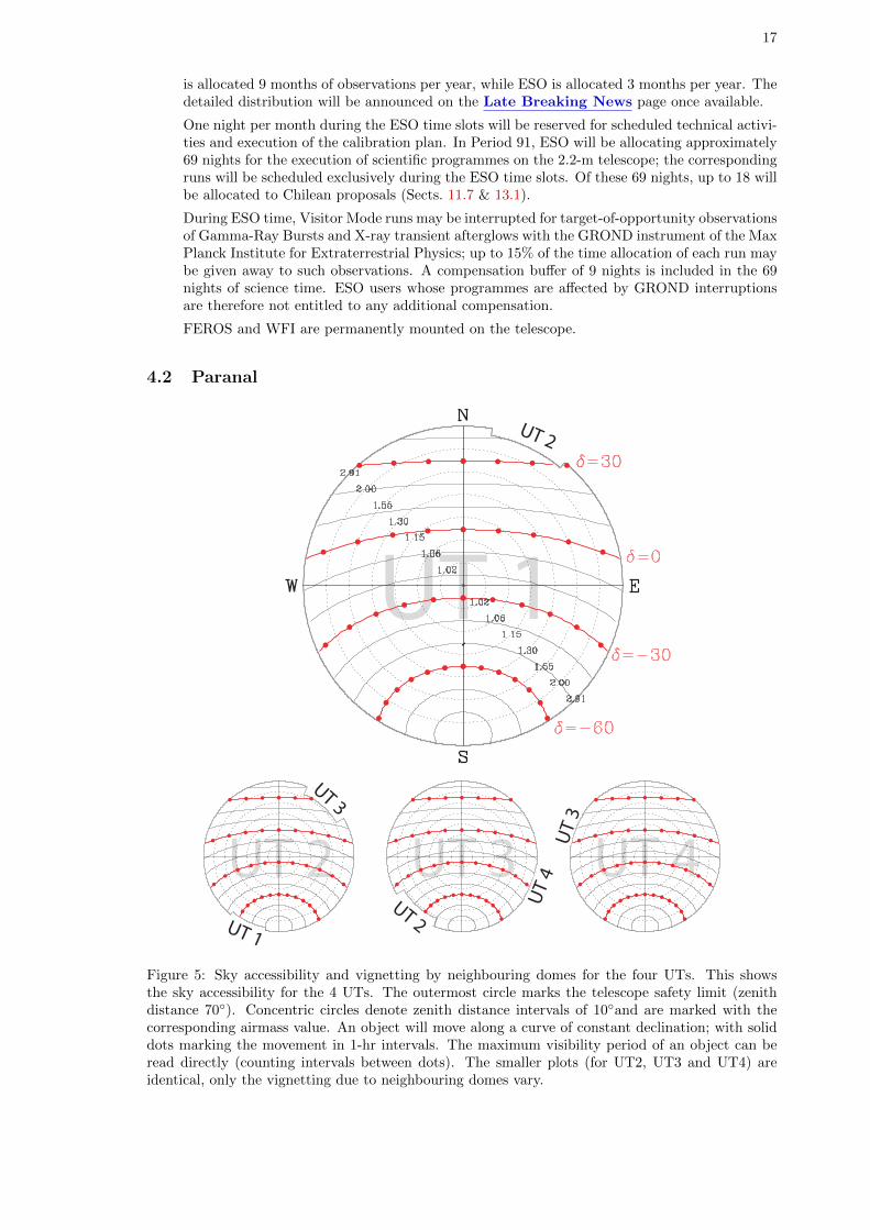
Figure 5: Sky accessibility and vignetting by neighbouring domes for the four UTs. This showsthe sky accessibility for the 4 UTs. The outermost circle marks the telescope safety limit (zenithdistance 70◦). Concentric circles denote zenith distance intervals of 10◦and are marked with thecorresponding airmass value. An object will move along a curve of constant declination; with soliddots marking the movement in 1-hr intervals. The maximum visibility period of an object can beread directly (counting intervals between dots). The smaller plots (for UT2, UT3 and UT4) areidentical, only the vignetting due to neighbouring domes vary.
18
4.2.1 The VLT Unit Telescopes (UTs)
The VLT consists of four Unit Telescopes (UTs). From a user’s perspective the four UTs can beregarded as identical. The Paranal Observatory site is located at 70◦25′ longitude West, 24◦40′
latitude South, at an altitude of 2635m.
Each UT primary mirror is a single Zerodur blank of diameter 8.20 m, the secondary has a diameterof 1.12 m. The UTs have four foci: two Nasmyth, one Cassegrain, and one Coude. They are Alt–Az mounted and cannot observe at zenith distances less than 4◦ or larger than 70◦. The VLTInterferometer only operates at zenith distances less than 60◦.
4.2.2 UTs Performance
• Pointing and tracking: The UTs have a pointing accuracy of 3′′ RMS. The expectedtracking accuracy under nominal wind load is 0.′′1 rms over 30 minutes when field stabilizationis active. The UTs also have the capability of tracking targets with additional velocities (e.g.Solar System targets) under full active optics control. Proposers who need this capabilityshould specify the additional velocities in RA and Dec for their targets.
• Active optics guiding: For all observations a guide star is used for acquisition, activeoptics, and field stabilization. The typical guide star magnitude ranges from R=11 to R=14(in optimal conditions). Observations for which no suitable guide star exists cannot be carriedout.
• Adaptive optics guiding (VLTI only): The Coude foci of the UTs are equipped withMACAO (Multi Application Curvature Adaptive Optics) units, which can be used with naturalguide stars with 1 <V < 17, seeing < 1.5′′, τ0 > 2.0 ms and airmass < 1.7. The distance ofthe natural guide star from the science target must be less than 57.5′′. For observations usingthe fringe tracker FINITO, V< 15, distance < 13′′.
4.2.3 Laser Guide Star facility on UT4
Important note: The Laser Guide Star Facility is expected to be decommissioned at the endof Period 92 to allow for the installation of the Deformable Secondary Mirror on UT4, part of theAdaptive Optics Facility. All programmes requiring its use should therefore be completed by then.
UT4 is equipped with a sodium laser that can create an artificial point source to be used withNACO and SINFONI. A tip-tilt star (TTS) is always necessary to correct for tip and tilt. However,SINFONI and NACO can be used with the Laser Guide Star but without a TTS, using the seeing-enhancer mode. Please note that the TTS can be both fainter and further away from the sciencetarget than natural guide stars (NGS), thus giving users access to a larger fraction of the sky.
Observations using the Laser Guide Star (LGS) require more stringent observing conditions thanobservations using natural guide stars. The transparency needs to be clear (CLR) or photometric,the airmass constraints are tighter and the atmosphere must be quiet (i.e. good seeing and a weakor absent jet stream). Further note that for operational reasons, the LGSF is currently scheduledin blocks of typically one week per month. The LGSF is offered with NACO and SINFONI in bothService Mode and Visitor Mode.
The peak K-band Strehl ratio achieved with the LGS in ideal conditions is around 20%. Thisdepends on many factors, so users are encouraged to use the SINFONI and NACO ETCs.
The point at which one should consider using the laser instead of a natural guide star can beestimated with the ETCs. Although the details depend on the distance of the NGS/TTS from thescience target, the airmass and the vertical profile of the turbulence, the magnitude at which oneshould consider using the laser is around R=13.5 to 14.
A programme that requires observations using both an NGS and the LGS should separate theseinto two distinct runs in the proposal form.
During Period 90, PARSEC, the current laser used by the Laser Guide Star Facility will likely be
19
decommissioned. It will be replaced by a prototype of the laser used by the coming Adaptive OpticsFacility. Its commissioning is expected to be completed by end of February 2013. Provided that thenew laser is successfully commissioned, both the delivered power and the number of nights duringwhich the LGSF can be used every month will be significantly increased.
4.2.4 The ATs (VLTI only)
The VLT Interferometer is complemented by an array of relocatable 1.8-m Auxiliary Telescopes(ATs). For Period 91 the ATs are offered with MIDI and AMBER. The baselines offered for thisperiod are specified at the VLTI baseline page.
The ATs are equipped with STRAP units, which provide tip-tilt correction for targets with −1.7 <V < 13.5. The distance of the guide star from the science target must be less than 57.5′′. Forobservations using the fringe tracker FINITO, V< 13.5, distance< 15′′.
While observations on AMBER and MIDI are not affected by the moon there are some restrictionsdue to the guiding of the telescopes.
• If the FLI is > 90%, guiding is not possible for stars fainter than 9th magnitude if the distanceto the moon is lower than 20 degrees.
• If the FLI is > 90%, guiding is impossible for any star if the distance to the moon is lowerthan 10 degrees.
Visiting astronomers are requested to check for potential limitations during the preparation of theirobservations.
4.2.5 VISTA
The Visible and Infrared Survey Telescope for Astronomy (VISTA) is a 4-m class wide field surveytelescope for the southern hemisphere. VISTA is located at ESO’s Cerro Paranal Observatory inChile on its own peak about 1.5 km from the four UTs. The telescope has an altitude-azimuthmount, and quasi-Ritchey-Chretien optics with a fast f/1 primary mirror giving an f/3.25 focus tothe instrument at Cassegrain. Shape and position of the mirrors are actively controlled by high-and low-order curvature wave front sensors (WFS) located inside the instrument focal plane. Thelow order WFSs are used simultaneously with the scientific observations.
VISTA is equipped with VIRCAM, which is described in Section 6.13.
4.2.6 VST
The VLT Survey Telescope (VST) is a 2.6-m wide field survey telescope for the southern hemisphere.It is located on the VLT platform on ESO’s Cerro Paranal Observatory and is equipped with justone focal plane instrument, OmegaCAM, which is described in Section 6.14.
The telescope has an altitude-azimuth mount with a f/5.5 modified Ritchey-Chretien optical layout.It contains an actively controlled meniscus primary mirror, a hexapod driven secondary mirror andan image analysis system. It also contains two interchangeable correctors: one is a high-throughputtwo-lens corrector which provides high throughput from the u to the z band, the other containsan Atmospheric Dispersion Corrector (ADC) for observations at lower elevations. The throughputof the ADC is very low in the u band. However, since it has not been demonstrated to improvesignificantly the image quality in regular operations, the ADC is not offered. The entrance windowof the OmegaCAM cryostat is the final optical element.
The VST operates from the u to the z band, preserving, within a corrected field of view of 1 by 1degree, the excellent seeing conditions achievable at the Cerro Paranal site.
20
4.2.7 Paranal meteorological conditions
Extensive statistical information on meteorological conditions on Paranal (seeing, wind, watervapour etc.) can be found on the Paranal Web page. Information about general climate andseismic statistics can also be found there. Wind statistics at Paranal show that the wind speed isbetween 12 and 15 m/s ∼ 10% of the time. These conditions allow observations to be made onlywith the telescope pointing down wind. Predominant winds blow from the North.
4.3 Chajnantor
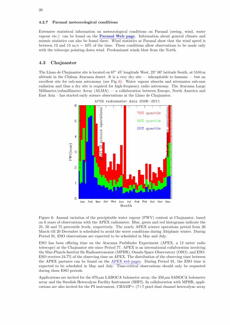
The Llano de Chajnantor site is located on 67◦ 45′ longitude West, 23◦ 00′ latitude South, at 5104 maltitude in the Chilean Atacama desert. It is a very dry site — inhospitable to humans — but anexcellent site for sub-mm astronomy (see Fig. 6). Water vapour absorbs and attenuates sub-mmradiation and thus a dry site is required for high-frequency radio astronomy. The Atacama LargeMillimeter/submillimeter Array (ALMA) — a collaboration between Europe, North America andEast Asia – has started early science observations at the Llano de Chajnantor.
Figure 6: Annual variation of the precipitable water vapour (PWV) content at Chajnantor, basedon 6 years of observations with the APEX radiometer. Blue, green and red histograms indicate the25, 50 and 75 percentile levels, respectively. The yearly APEX science operations period from 20March till 20 December is scheduled to avoid the worst conditions during Altiplanic winter. DuringPeriod 91, ESO observations are expected to be scheduled in May and July.
ESO has been offering time on the Atacama Pathfinder Experiment (APEX, a 12 meter radiotelescope) at the Chajnantor site since Period 77. APEX is an international collaboration involvingthe Max-Planck-Institut fur Radioastronomie (MPIfR), Onsala Space Observatory (OSO), and ESO.ESO receives 24.7% of the observing time on APEX. The distribution of the observing time betweenthe APEX partners can be found on the APEX web pages. During Period 91, the ESO time isexpected to be scheduled in May and July. Time-critical observations should only be requestedduring these ESO periods.
Applications are invited for the 870µm LABOCA bolometer array, the 350µm SABOCA bolometerarray and the Swedish Heterodyne Facility Instrument (SHFI). In collaboration with MPIfR, appli-cations are also invited for the PI instrument, CHAMP+ (7+7 pixel dual channel heterodyne array
21
covering 620 to 720 GHz and 780 to 900 GHz), and FLASH (280-370 GHz + 385-495 GHz sidebandseparating receiver). Finally, in collaboration with its instrument team, applications are invited forthe PI instrument, Z-Spec (190-308 GHz single-beam diffraction-grating spectrograph).
Observations will be done for up to 24 hours per day, but users should be aware that afternoonconditions are often significantly worse than those during the night or morning. Observations usinghigh frequency instruments (SHFI/APEX-T2, SHFI/APEX-3, SABOCA) should avoid the after-noon time. All observations will be done in Service Mode by the local APEX staff. In exceptionalcases (e.g. moving targets), remote observing from Bonn (in collaboration with MPIfR) can beconsidered. No Visitor Mode proposals will be accepted for APEX.
The wobbling secondary is offered for all SHFI proposals. The wobbler can also be used withLABOCA and SABOCA to obtain sensitive observations of isolated point sources with accuratelyknown positions. The APEX wobbler can chop in azimuth up to 300′′ with rates up to 2 Hz.
Because the LABOCA detectors need to be cooled to 0.3 K using liquid Helium, the LABOCAobservations will be scheduled in continuous blocks of observing time. This will make time-criticalobservations during ESO time difficult to schedule. The re-filling of the Helium will generally bedone during the afternoon, with a shorter re-cycling procedure 11 to 12 hours later. The exactschedule will be optimised according to the RA pressure on the targets.
SABOCA also has a liquid Helium cooled cryostat, but as the hold time is 48 hours, the observationscan be scheduled with more flexibility. During Period 91, SABOCA is expected to be available onlyin July 2013.
All APEX proposals must clearly indicate the requested PWV for their observations in Box 12 ofthe proposal form. Figure 6 gives the statistical distribution of PWV throughout the year. Theneed for good PWV conditions needs to be justified in the proposal.
For each proposal, all observations with the same APEX instrument should be merged into a singlerun. This also accounts for the different receivers of SHFI, which should be grouped into a singlerun. Different run ID’s should only be used for different instruments (or in Large Programmeproposals, for observations to take place in different periods). This restriction is needed to increasethe observing efficiency at APEX.
Proposals requesting time from different APEX partners are required to mention the amount oftime requested from MPIfR, Sweden or Chile in Box 5.
More on APEX, including SHFI, LABOCA and SABOCA observing time calculators, can be foundat www.apex-telescope.org.
5 Scientific Instruments: La Silla
5.1 SofI — Son of ISAAC, on the NTT
SofI is the infrared spectro-imager mounted on the NTT. It is equipped with a Hawaii HgCdTe1024×1024 detector.
SofI is only offered for Visitor Mode observations and has the following observing modes:
• Imaging with plate-scales of 0.273 and 0.288′′/pixel using broad and narrow-band filters in thewavelength range 0.9–2.5µm. SofI provides a field of view of 4.92′. A Js filter similar to thaton ISAAC is available in addition to the standard J filter.
• High time-resolution imaging in Burst and FastPhot mode with integration times of the orderof a few tens of milliseconds via hardware windowing of the detector array. Information abouttechnical details, restrictions, and overheads is available in the SofI user manual.
• Low resolution (R = 600), 0.93–2.54µm spectroscopy with fixed width slits of 0.6, 1 and 2′′.
• Medium resolution (R = 1500) spectroscopy with the same fixed width slits.
• 0.9–2.5 micron imaging polarimetry.
22
Up-to-date information and documentation on the instrument are available at:http://www.eso.org/sci/facilities/lasilla/instruments/sofi/.
5.1.1 ESO Public Spectroscopic Surveys
In Period 91, there will be up to 30 NTT nights assigned to the ESO Public Spectroscopic Surveyentitled “PESSTO: Public ESO Spectroscopic Survey for Transient Objects”. Further details areavailable on the ESO Public Surveys Projects webpage. Proposers should check that their sci-ence goals do not duplicate those of this public survey.
5.2 EFOSC2 — ESO Faint Object Spectrograph and Camera 2, on theNTT
EFOSC2 is a very versatile instrument for low resolution spectroscopy and imaging in the visi-ble and near UV. It also has polarimetric capabilities (both for imaging and spectroscopy) and acoronagraphic mode, and it can efficiently perform multi-object spectroscopy.
EFOSC2 is only offered in Visitor Mode.
The instrument is equipped with a Loral/Lesser UV-flooded 2k×2k CCD. The pixel size is 0.12′′,with a corresponding field of view of 4.1′.
The grisms cover the 318–1100 nm wavelength range, with resolutions ranging from 100 to 1000.Slits from 0.5′′ to 15′′ are available.
Two volume-phase holographic grisms (VPHG) have been offered for medium resolution spec-troscopy. The blue grism (#19) covers the wavelength range from 440 nm to 510 nm, at a resolutionof up to ∼ 4000 with a 0.5′′ slit, while the red grism (#20) covers the range 605 nm to 715 nm at aresolution of up to 4000 with the 0.5′′ slit. The grisms introduce a lateral shift of the beam, so theeffective field of view is 3.1′ and 2.7′ for the blue and red VPHGs respectively.
The wavelength range of the blue VPHG grism (#19) can be extended to cover a more useful range(e.g. reaching the Mg triplet at 520 nm or the G-band at 430 nm) by using slits offset to the redor blue. With 15 mm offsets (corresponding to wavelength offsets of 21.8 nm) the wavelength rangecoverage for the grism #19 is 418 nm to 532 nm (the full range is achievable by combining red offsetand blue offset spectra). There are offset slits available with 15mm offsets to the blue and red withthe full range of slit widths available for the normal slits. These slits can of course be used with anyother grism, with the wavelength offset depending on the grism dispersion. See the web pages formore details.
Up to 5 MOS plates can be loaded simultaneously. They are punched off-line, so additional platescan be punched at any time. To create multi-slit masks, pre-imaging must be acquired usingEFOSC2 with the same position angle as for the actual observations, typically one day before thespectroscopic observations. Therefore, NTT observers in La Silla may be asked to give up to 20minutes of their allocated time for pre-imaging observations for subsequent EFOSC2 MOS runs.
The coronagraphic mode features focal stops of 8.0′′ and 4.0′′ and a Lyot pupil mask.
The polarimetric measurements are performed using either a half-wave plate or a quarter-waveplate. These super-achromatic plates can be moved into the optical path and rotated to measurethe polarisation at different angles without rotating the whole instrument. The plates are housedin separate units, and only one unit (plate) per night can be used. Note that since EFOSC2 ismounted at the NTT Nasmyth B focus there is strong instrumental polarisation that varies withtelescope pointing. Users should allow time for additional observations of unpolarised standard starsto correct for this.
For imaging, a set of standard Bessell and Gunn filters as well as several narrow-band filters areavailable. See the EFOSC2 filter page for details.
Up-to-date information and documentation on the instrument are available on the EFOSC2 web page.
23
5.2.1 ESO Public Spectroscopic Surveys
In Period 91, there will be up to 45 NTT nights assigned to the ESO Public Spectroscopic Surveyentitled “PESSTO: Public ESO Spectroscopic Survey for Transient Objects”. Further details areavailable on the ESO Public Surveys Projects webpage. Proposers should check that their sci-ence goals do not duplicate those of this public survey.
5.3 HARPS — High Accuracy Radial velocity Planetary Search, on the3.6-m
HARPS is the ESO facility for the measurement of very precise radial velocities. It is fed by twofibres from the Cassegrain focus of the 3.6-m telescope.
HARPS is offered in Visitor Mode only during Period 91.
The instrument is built to obtain very precise radial velocities (∼1 m/s). To achieve this goal,HARPS is designed as an echelle spectrograph fed by a pair of fibres and is contained in a vacuumvessel to avoid spectral drift due to temperature and air pressure variations. One of the two fibrescollects the starlight, while the second is used to either record a Th-Ar reference spectrum or thebackground sky simultaneously. The two HARPS fibres (object + sky or Th-Ar) have a sky apertureof 1′′, resulting in a resolving power of 115,000. Both fibres are equipped with an image scrambler toprovide a uniform spectrograph pupil illumination, independent of pointing decentring. The spectralcoverage distributed over the echelle orders 89-161 is 378 nm–691 nm. As the detector consists of amosaic of 2 CCDs (altogether 4k×4k, 15µm pixels), one spectral order (N=115, from 530 to 533nm)is lost in the gap between the two chips.
HARPS reaches a S/N of 110 per pixel at 550 nm for a MV = 6 G2V star in 1 minute (1′′ seeing,airmass = 1.2). When using the Simultaneous Thorium Reference Method, which is the mode forachieving the highest radial velocity accuracy, this signal-to-noise ratio should be sufficient to achievea photon-noise-dominated radial velocity accuracy of about 0.90 m/s. Taking into account errorsintroduced by the guiding, focus, and instrumental uncertainties, a global radial velocity accuracy ofabout 1 m/s RMS is achieved. This is obtained for spectral types later than G and for non-rotatingstars (v sin i < 2 km/s).
In simultaneous Th-Ar mode, HARPS users should strictly follow the calibrations foreseen by theCalibration Plan, which includes a number of biases, flatfields and Th-Ar exposures taken beforethe night.
Since Period 89, a Fabry-Perot Calibration System (FPCS) is available as an alternative calibrationsource for simultaneous drift measurements. The Fabry-Perot etalon is illuminated by a super-continuum laser source providing a uniform density of lines and a relatively flat spectrum over theHARPS wavelength range.
In the FPCS case, no contamination is seen due to the strong Ar lines; the photon noise is half ofthat measured in the ThAr lamp (i.e. ∼ 4 cm s−1), while the stability within one night is betterthan ∼ 10 cm s−1.
Programmes that require very high precision and for which contamination of the stellar spectra byThAr should be avoided might benefit from the use of the FPCS. However, we caution users thatthe long term behavior is still under study.
HARPS is equipped with its own pipeline (installed on La Silla). This pipeline provides the visitingastronomer with extracted and wavelength calibrated spectra in near real-time (in all observingmodes). When the Simultaneous Thorium Reference Method is applied, the pipeline delivers preciseradial velocities (RV, relative to the solar system barycentre) for late-type stars whose RV is knownwithin 1–2 km/s, provided that a set of standard calibrations has been executed in the afternoon.
An additional fibre, with a larger aperture (1.4′′ on the sky) is available for HARPS. This highefficiency mode is dubbed “EGGS”. The higher efficiency compared to the base mode (referred toas “HAM”) is achieved by reducing flux losses through the larger fibre aperture and by dispensingthe image scrambler. The resolving power of the mode, due to the larger fibre, decreases to about80 000. This mode is particularly useful for faint objects. Its peak efficiency is 11% and the gain in
24
flux with respect to the HARPS base mode is 75% at 530 nm with a seeing of 0.8′′. This mode is nowequipped with only one fibre, therefore neither the sky subtraction nor the simultaneous Thoriumreference method can be applied. The intrinsic instrument stability (better than 1 m/s) is superiorto the EGGS radial velocity accuracy; the achievable radial velocity accuracy of the EGGS modeis limited by systematics and is ∼10 m/s RMS. The amount of diffuse light in the spectrograph is∼4%.
The EGGS mode is also supported by a full reduction pipeline running at the telescope. Both rawand reduced data will be delivered to the user. The HARPS baseline mode and the high efficiencymode can both be used during the same night. The time needed to switch from one mode to theother is about 1 minute. For radial velocity measurements a calibration sequence similar to that ofthe base mode should be used.
A polarimeter is also available on HARPS. The unit is able to perform both circular and linearpolarimetry. Measurements of the throughput indicate a light loss with respect to the base modeof HARPS in the range of 20% to 30%, increasing to ≈40% in the bluest orders. Instrumentalpolarization is not detected down to a level of 10−4 for zenith angles smaller than 60 degrees. Closerto the horizon instrumental polarization grows rapidly if the Atmospheric Dispersion Corrector isin the light beam. HARPS polarimetric data are reduced by the online pipeline.
Up-to-date information and documentation on the instrument, including the user manual and ex-posure time calculator, are available on the HARPS web page.
5.4 FEROS — Fibre-fed Extended Range Optical Spectrograph, on the2.2-m
FEROS is ESO’s high-resolution, high-efficiency spectrograph on the 2.2-m telescope. It is a bench-mounted, thermally controlled, prism-cross-dispersed echelle spectrograph, providing, in a singlespectrogram spread over 39 orders, almost complete1 spectral coverage from ∼ 350 to ∼ 920 nm ata resolution of 48 000.
The available ESO time-slots at the 2.2-m telescope, as defined in Section 4.1, need to be taken intoaccount for proposal preparation.
FEROS is offered in Visitor Mode only.
The spectrograph is fed by two fibres, allowing simultaneous spectra of an object and either thesky or a calibration source (normally a wavelength calibration lamp). The fibres are illuminated viaapertures of 2.′′0 and are separated by 2.′9.
The mechanical and thermal stability of FEROS is such that the wavelength calibration obtainedduring the day is sufficiently accurate for most purposes. Additional night-time calibrations arenot necessary. Although not intended as a ‘radial velocity machine’, precise radial velocity work(accuracies of ∼ 25 m/s or better) is possible, especially via the Object-Calibration mode.
A dedicated pipeline provides, in almost real time, extracted 1-dimensional, wavelength calibratedspectra, which can be used as a preview and to check S/N. The core of the FEROS pipeline isincluded in the standard MIDAS distribution and, together with the FEROS Data Reduction System(FEROS-DRS) package (provided at the FEROS web site), can be used to re-reduce the data toobtain publication quality results.
Up-to-date information and documentation on the instrument can be found via the FEROS web page.
5.5 WFI — Wide Field Imager, on the 2.2-m
The Wide Field Imager (WFI) has a field of view of 34′×33′ and is composed of a mosaic of 4×2CCD detectors with a pixel size of 0.24′′and narrow inter-chip gaps, yielding a filling factor of 95.9%.It offers excellent sensitivity from the atmospheric UV cut-off to the near IR. All applicants shouldtake the availability restrictions of the 2.2-m during ESO time and the corresponding lunar phasesinto account (Section 4.1).
1The two spectral ranges 853.4–854.1 nm and 886.2–887.5 nm are lost due to non-overlap of the spectral orders.
25
WFI is offered in Visitor Mode only.
The filter storage and exchange mechanism, with 50 positions, accommodates 11 broad-band filters(including a fully transparent one), 27 medium-band filters covering the whole wavelength range,and 8 narrow-band filters centred at [OIII], [SII], Hα and a few other wavelengths. The largenumber of medium- and narrow-band filters are specifically selected to support the determinationof photometric redshifts of distant objects.
We summarise the performance of WFI in Table 1. The table should only be used as a quick guideof feasibility.
Table 1: WFI limiting magnitudes
Filter Limiting magnitude (S/N=5)U 23.8B 26.0V 25.5R 25.3I 24.3
The limiting magnitudes correspond to a one-hour integration with dark sky, clear conditions, aseeing FWHM of 0.′′8 and an airmass of 1.2, and have been calculated for a point source of zerocolour (A0V star). To estimate the operational overheads of your proposed observations, pleaseconsult Chapter 5.1. of the WFI handbook. Note that for dithering offsets larger than 150′′, theoverhead increases by 1 minute per offset. These extra overheads must be properly accounted for.
Up-to-date information and documentation on the instrument can be found via the WFI web page.
6 Scientific Instruments: Paranal
6.1 CRIRES, Cryogenic high-resolution IR Echelle Spectrograph
CRIRES is the infrared (0.95 µm – 5.2 µm) high–resolution spectrograph located at the NasmythA focus of UT1. It provides long–slit (39′′) spectroscopy with a spatial sampling of ≈ 0.1′′. Spatialresolution and signal–to–noise ratio can be maximized by the optional use of a MACAO adaptiveoptics system equipped with an optical (R band) wavefront sensor. Good correction is obtainedwith stars as faint as R∼ 14 mag under average seeing conditions, while moderate image qualityimprovement is seen with stars as faint as R∼16 mag under good seeing (FWHM < 0.6.′′) conditions.
Important note: Large Programmes using CRIRES will not be accepted in Period 91.
The main optical elements consist of a prism acting as a pre–disperser and a 31.6 lines/mm echellegrating. Total spectral coverage per individual wavelength setting is ∼ λ/70 thanks to an array offour 1024 x 512 Aladdin III detectors. Acquisition and guiding are performed by the means of a slitviewer equipped with an additional Aladdin III detector and a series of five filters (J,H,K and twoneutral density H filters).
Possible slit widths are 0.2 and 0.4′′, providing a resolving power of R ' 100, 000 and R ' 50, 000,respectively. Standard and free wavelength settings are offered for both Visitor Mode (Section 12.1)and Service Mode (Section 12.2). For settings shortward of ∼ 3µm, the blue and red ends of thewavelength coverage can be affected by contamination from adjacent orders and lack of illuminationreproducibility. Tables 3 and 4 of the User Manual report the spectral range free of these effects forall standard settings. Starting from Period 90, the implementation of the metrology system shouldensure the reproducibility of the wavelength scale to sub-pixel accuracy. Despite the availability ofa Krypton and ThAr lamps and of the N2O and CO gas-cells, the lack of wavelength calibrationlines affect some settings. During P89 a UNe lamp for wavelength calibration was tested that in thefuture may act as a complimentary calibration source.
Provided an adequate observational strategy is followed, radial velocity measurements to betterthan ≈ 20m s−1 can be reached for stars showing a sufficient number of spectral features. See the
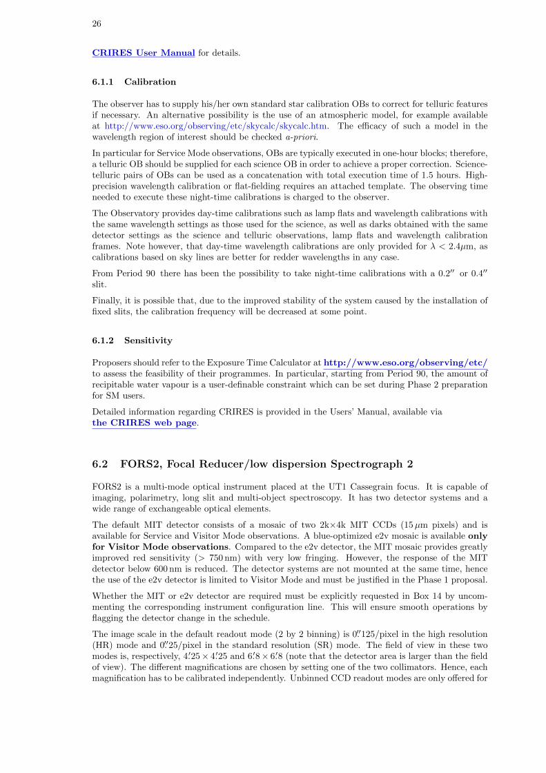
26
CRIRES User Manual for details.
6.1.1 Calibration
The observer has to supply his/her own standard star calibration OBs to correct for telluric featuresif necessary. An alternative possibility is the use of an atmospheric model, for example availableat http://www.eso.org/observing/etc/skycalc/skycalc.htm. The efficacy of such a model in thewavelength region of interest should be checked a-priori.
In particular for Service Mode observations, OBs are typically executed in one-hour blocks; therefore,a telluric OB should be supplied for each science OB in order to achieve a proper correction. Science-telluric pairs of OBs can be used as a concatenation with total execution time of 1.5 hours. High-precision wavelength calibration or flat-fielding requires an attached template. The observing timeneeded to execute these night-time calibrations is charged to the observer.
The Observatory provides day-time calibrations such as lamp flats and wavelength calibrations withthe same wavelength settings as those used for the science, as well as darks obtained with the samedetector settings as the science and telluric observations, lamp flats and wavelength calibrationframes. Note however, that day-time wavelength calibrations are only provided for λ < 2.4µm, ascalibrations based on sky lines are better for redder wavelengths in any case.
From Period 90 there has been the possibility to take night-time calibrations with a 0.2′′ or 0.4′′
slit.
Finally, it is possible that, due to the improved stability of the system caused by the installation offixed slits, the calibration frequency will be decreased at some point.
6.1.2 Sensitivity
Proposers should refer to the Exposure Time Calculator at http://www.eso.org/observing/etc/to assess the feasibility of their programmes. In particular, starting from Period 90, the amount ofrecipitable water vapour is a user-definable constraint which can be set during Phase 2 preparationfor SM users.
Detailed information regarding CRIRES is provided in the Users’ Manual, available viathe CRIRES web page.
6.2 FORS2, Focal Reducer/low dispersion Spectrograph 2
FORS2 is a multi-mode optical instrument placed at the UT1 Cassegrain focus. It is capable ofimaging, polarimetry, long slit and multi-object spectroscopy. It has two detector systems and awide range of exchangeable optical elements.
The default MIT detector consists of a mosaic of two 2k×4k MIT CCDs (15µm pixels) and isavailable for Service and Visitor Mode observations. A blue-optimized e2v mosaic is available onlyfor Visitor Mode observations. Compared to the e2v detector, the MIT mosaic provides greatlyimproved red sensitivity (> 750 nm) with very low fringing. However, the response of the MITdetector below 600 nm is reduced. The detector systems are not mounted at the same time, hencethe use of the e2v detector is limited to Visitor Mode and must be justified in the Phase 1 proposal.
Whether the MIT or e2v detector are required must be explicitly requested in Box 14 by uncom-menting the corresponding instrument configuration line. This will ensure smooth operations byflagging the detector change in the schedule.
The image scale in the default readout mode (2 by 2 binning) is 0.′′125/pixel in the high resolution(HR) mode and 0.′′25/pixel in the standard resolution (SR) mode. The field of view in these twomodes is, respectively, 4.′25× 4.′25 and 6.′8× 6.′8 (note that the detector area is larger than the fieldof view). The different magnifications are chosen by setting one of the two collimators. Hence, eachmagnification has to be calibrated independently. Unbinned CCD readout modes are only offered for
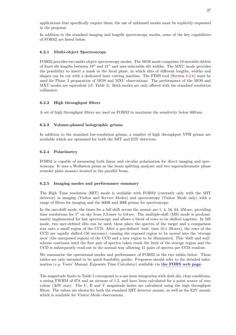
27
applications that specifically require them; the use of unbinned modes must be explicitly requestedin the proposal.
In addition to the standard imaging and longslit spectroscopy modes, some of the key capabilitiesof FORS2 are listed below.
6.2.1 Multi-object Spectroscopy
FORS2 provides two multi-object spectroscopy modes. The MOS mode comprises 19 movable slitletsof fixed slit lengths between 19′′ and 21′′ and user-selectable slit widths. The MXU mode providesthe possibility to insert a mask in the focal plane, in which slits of different lengths, widths andshapes can be cut with a dedicated laser cutting machine. The FIMS tool (Section 6.2.6) must beused for Phase 2 preparation of MOS and MXU observations. The performance of the MOS andMXU modes are equivalent (cf. Table 3). Both modes are only offered with the standard resolutioncollimator.
6.2.2 High throughput filters
A set of high throughput filters are used on FORS2 to maximize the sensitivity below 600 nm.
6.2.3 Volume-phased holographic grisms
In addition to the standard low-resolution grisms, a number of high throughput VPH grisms areavailable which are optimised for both the MIT and E2V detectors.
6.2.4 Polarimetry
FORS2 is capable of measuring both linear and circular polarisation for direct imaging and spec-troscopy. It uses a Wollaston prism as the beam splitting analyser and two superachromatic phaseretarder plate mosaics located in the parallel beam.
6.2.5 Imaging modes and performance summary
The High Time resolution (HIT) mode is available with FORS2 (currently only with the MITdetector) in imaging (Visitor and Service Modes) and spectroscopy (Visitor Mode only) with arange of filters for imaging and the 600B and 300I grisms for spectroscopy.
In the one-shift mode, the times for a full shift across the mosaic are 1, 4, 16, 64, 256 sec, providingtime resolutions for 1′′ on sky from 2.3 msec to 0.6 sec. The multiple-shift (MS) mode is predomi-nantly implemented for fast spectroscopy and allows a block of rows to be shifted together. In MSmode, two user-defined slits can be used; these place the spectra of the target and a comparisonstar onto a small region of the CCD. After a pre-defined ‘wait’ time (0.1–20 secs), the rows of theCCD are rapidly shifted (50 microsec), causing the exposed region to be moved into the ‘storagearea’ (the unexposed region) of the CCD and a new region to be illuminated. This ‘shift and wait’scheme continues until the first pair of spectra taken reach the limit of the storage region and theCCD is subsequently read-out in the normal way allowing 41 pairs of spectra per CCD readout.
We summarise the operational modes and performance of FORS2 in the two tables below. Thesetables are only intended to be quick feasibility guides. Proposers should refer to the detailed infor-mation (e.g. Users’ Manual, Exposure Time Calculator) available via the FORS web page.
The magnitude limits in Table 2 correspond to a one hour integration with dark sky, clear conditions,a seeing FWHM of 0.′′8 and an airmass of 1.2, and have been calculated for a point source of zerocolour (A0V star). The U, B and V magnitude limits are calculated using the high throughputfilters. The values are shown for both the standard MIT detector mosaic, as well as the E2V mosaicwhich is available for Visitor Mode observations.
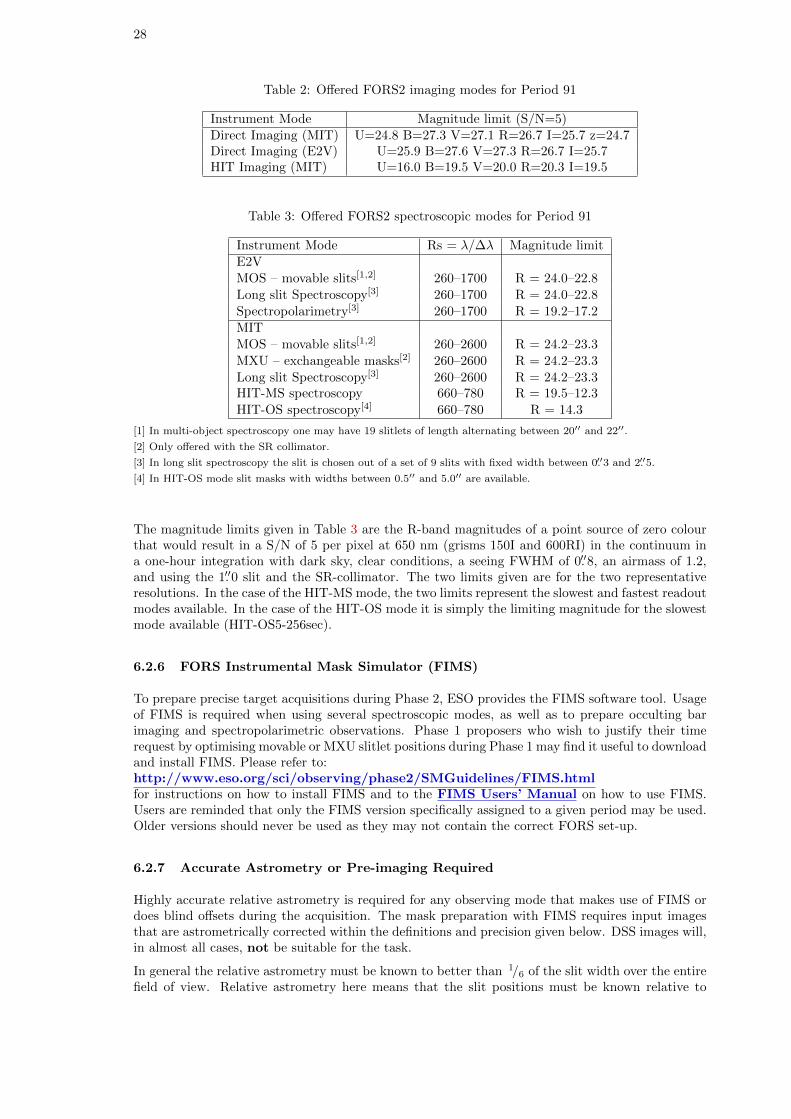
28
Table 2: Offered FORS2 imaging modes for Period 91
Instrument Mode Magnitude limit (S/N=5)Direct Imaging (MIT) U=24.8 B=27.3 V=27.1 R=26.7 I=25.7 z=24.7Direct Imaging (E2V) U=25.9 B=27.6 V=27.3 R=26.7 I=25.7HIT Imaging (MIT) U=16.0 B=19.5 V=20.0 R=20.3 I=19.5
Table 3: Offered FORS2 spectroscopic modes for Period 91
Instrument Mode Rs = λ/∆λ Magnitude limitE2VMOS – movable slits[1,2] 260–1700 R = 24.0–22.8Long slit Spectroscopy[3] 260–1700 R = 24.0–22.8Spectropolarimetry[3] 260–1700 R = 19.2–17.2MITMOS – movable slits[1,2] 260–2600 R = 24.2–23.3MXU – exchangeable masks[2] 260–2600 R = 24.2–23.3Long slit Spectroscopy[3] 260–2600 R = 24.2–23.3HIT-MS spectroscopy 660–780 R = 19.5–12.3HIT-OS spectroscopy[4] 660–780 R = 14.3
[1] In multi-object spectroscopy one may have 19 slitlets of length alternating between 20′′ and 22′′.
[2] Only offered with the SR collimator.
[3] In long slit spectroscopy the slit is chosen out of a set of 9 slits with fixed width between 0.′′3 and 2.′′5.
[4] In HIT-OS mode slit masks with widths between 0.5′′ and 5.0′′ are available.
The magnitude limits given in Table 3 are the R-band magnitudes of a point source of zero colourthat would result in a S/N of 5 per pixel at 650 nm (grisms 150I and 600RI) in the continuum ina one-hour integration with dark sky, clear conditions, a seeing FWHM of 0.′′8, an airmass of 1.2,and using the 1.′′0 slit and the SR-collimator. The two limits given are for the two representativeresolutions. In the case of the HIT-MS mode, the two limits represent the slowest and fastest readoutmodes available. In the case of the HIT-OS mode it is simply the limiting magnitude for the slowestmode available (HIT-OS5-256sec).
6.2.6 FORS Instrumental Mask Simulator (FIMS)
To prepare precise target acquisitions during Phase 2, ESO provides the FIMS software tool. Usageof FIMS is required when using several spectroscopic modes, as well as to prepare occulting barimaging and spectropolarimetric observations. Phase 1 proposers who wish to justify their timerequest by optimising movable or MXU slitlet positions during Phase 1 may find it useful to downloadand install FIMS. Please refer to:http://www.eso.org/sci/observing/phase2/SMGuidelines/FIMS.htmlfor instructions on how to install FIMS and to the FIMS Users’ Manual on how to use FIMS.Users are reminded that only the FIMS version specifically assigned to a given period may be used.Older versions should never be used as they may not contain the correct FORS set-up.
6.2.7 Accurate Astrometry or Pre-imaging Required
Highly accurate relative astrometry is required for any observing mode that makes use of FIMS ordoes blind offsets during the acquisition. The mask preparation with FIMS requires input imagesthat are astrometrically corrected within the definitions and precision given below. DSS images will,in almost all cases, not be suitable for the task.
In general the relative astrometry must be known to better than 1/6 of the slit width over the entirefield of view. Relative astrometry here means that the slit positions must be known relative to

29
those of the reference stars in the field of view with the given precision. These relative astrometriccalibrations are fulfilled if your FIMS preparation is based on images taken with FORS1 after March22, 2003 or on any FORS2 images.
An important exception is multi-object spectroscopy with unbinned CCD readout modes: userswishing to apply for this mode must request additional pre-imaging, even if previous FORS1 orFORS2 images are available.
If images of adequate quality are not available, Phase 1 proposers must apply for pre-imagingdefined as a separate run in the Phase 1 proposal and clearly marked as pre-imaging (PRE-IMG) inthe “Instrument configuration” section of the proposal. Failure to do so will result in the deductionof the pre-imaging time from the time allocation assigned to the main project, if the programmeis approved for execution. As a rule, pre-imaging runs are carried out in Service Mode, even forprogrammes whose main (spectroscopic) runs are conducted in Visitor Mode.
For further information, FORS2 proposers should visit the FORS web page.
6.3 FLAMES, Fibre Large Array Multi-Element Spectrograph
FLAMES is the multi-object, intermediate and high resolution spectrograph of the VLT. Mountedat the Nasmyth A platform of UT2, FLAMES can access targets over a large corrected field of view(25′ diameter). It consists of three main components:
• A Fibre Positioner (OzPoz) hosting two plates: while one plate is observing, the otherpositions the fibres for the subsequent observations. This limits the dead time between oneobservation and the next to less than 15 minutes, including the telescope preset and theacquisition of the next field.
• A medium-high resolution optical spectrograph, GIRAFFE, with three types of feeding fibresystems : MEDUSA, IFU, ARGUS.
• A link to the UVES spectrograph (Red Arm) via 8 single fibres of 1′′ entrance aperture.
Special observing software (FLAMES OS) coordinates the operation of the different subsystems,also allowing simultaneous acquisition of UVES and GIRAFFE observations with the observingmodes listed in Table 4. For combined observations, the exposure times for UVES and GIRAFFEdo not need to be the same. Note that it is not possible to observe simultaneously in two GIRAFFEmodes, or to observe the same target simultaneously with the two spectrographs.
For more detailed information on instrument setups and performance estimates the user is referredto the FLAMES web page.
6.3.1 Instrument Capabilities
GIRAFFE is a medium-high (R = 5, 600–48, 000) resolution spectrograph for the entire visiblerange, 370–950 nm. It is equipped with two gratings and several filters are available to select therequired spectral range. Five additional fibres allow simultaneous wavelength calibration of everyexposure. Each object can be observed in only one, or a fraction of, a single echelle order at once.The fibre system feeding GIRAFFE consists of the following components:
• Two MEDUSA slits, one per positioner plate: up to 132 separate objects (including skyfibres) are accessible in MEDUSA single fibre mode, each with an aperture of 1.′′2 on the sky.
• Two IFU slits: each IFU (deployable Integral Field Unit) consists of a rectangular array of 20microlenses of 0.′′52 each, giving an aperture of 2′′×3′′. For each plate there are 15 IFU unitsdedicated to objects and another 15 dedicated to sky measurements. In the latter, only thecentral fibre is present.
• One ARGUS slit: the large integral field unit ARGUS is mounted at the centre of oneplate of the fibre positioner and consists of a rectangular array of 22 × 14 microlenses. Two
30
Table 4: FLAMES Observational Capabilities
Spectro. Mode N. Objects Aperture [′′] R∗ Cover. CommentsUVES6/8 RED 6 or 8 (with sky) 1.0 47000 200 6 fib@520nmUVES7+1 RED 7 (with sky) 1.0 47000 200 +Sim.Calib.GIRAF HR MEDUSA 131a (with sky) 1.2 21000[1] λ /22 – λ/12GIRAF LR MEDUSA 131[2] (with sky) 1.2 7000[1] λ /7.5GIRAF HR IFU 15 (+15 sky) 2×3 32000[1] λ /22 – λ/12GIRAF LR IFU 15 (+15 sky) 2×3 11000[1] λ /7.5GIRAF HR ARGUS 1 11.5×7.3 32000[1] λ /22 – λ/12
or 6.6×4.2GIRAF LR ARGUS 1 11.5×7.3 11000[1] λ /7.5
or 6.6×4.2
[1] The resolving powers (R) given here are only average values, for more details see
http://www.eso.org/sci/facilities/paranal/instruments/flames/doc/ which contains a description of
all the GIRAFFE setups.
[2] The number of allocable buttons is 132, but only 131 spectra are fully covered on the detector.
magnification scales are available: “1:1” with a sampling of 0.′′52/microlens and a total apertureof 11.′′5×7.′′3, and “1:1.67” with 0.′′3/microlens and a total aperture of 6.′′6×4.′′2. In addition,15 ARGUS sky fibres can be positioned in the 25′ field.
GIRAFFE is equipped with one 2k×4k EEV CCD (15µm pixels), with a scale of 0.′′3/pixel inMEDUSA, IFUs and ARGUS direct mode, and a scale of 0.′′15/pixel in the 1.67 scale ARGUSmode. GIRAFFE is operated with 39 fixed setups (31 at high resolution + 8 at low resolutionmodes).
The standard readout mode of FLAMES-GIRAFFE is 225 kHz (unbinned) which ensures low read-out noise. A high-speed readout mode (625 kHz, unbinned, low gain) with increased readout noisebut less overheads is offered in Visitor Mode only. No pipeline support is available for this mode.
UVES is the high resolution spectrograph at UT2 of the VLT (see Section 6.4). It was designedto work in long slit mode but it has been possible to add a fibre mode (6 to 8 fibres, depending onsetup and/or mode) fed by the FLAMES positioner to its Red Arm only. Only three of the standardUVES Red setups are offered, with central wavelengths of 520, 580 and 860 nm respectively (seethe UVES Users’ Manual for details).
The standard readout mode of FLAMES-UVES is 225 kHz (unbinned) which ensures low readoutnoise. A high-speed readout mode (625 kHz, unbinned, low gain) with increased readout noise butless overheads is offered as well in Visitor Mode only. No pipeline support is available for this mode.
With an aperture on the sky of 1′′, the fibres project onto 5 UVES pixels giving a resolving power of∼47,000. For faint objects and depending on the spectral region, one or more fibres can be devotedto recording the sky contribution. In addition, for the 580 nm setup only, a separate calibrationfibre is available to acquire simultaneous ThAr calibration spectra. This allows very accurate radialvelocity determinations. In this configuration, 7 fibres remain available for targets on sky.
The upgrade of the MIT CCD in the UVES red arm in July 2009 has provided a marked increasein sensitivity in the 860-nm setting and decrease in fringing.
6.3.2 Observational Requirements
The operation of FLAMES requires the observer to have his/her own list of target coordinates, witha relative astrometric accuracy better than 0.′′3, when preparing Phase 2. Bad astrometry resultsin large losses at the fibre entrance and therefore in much poorer performance. Theminimum object separation is 11′′ for MEDUSA fibres. The Fibre Positioner is able to place thefibres with an accuracy better than 0.′′1. During Phase 2 it is necessary to run dedicated software(FPOSS) that assigns the fibres to the selected objects. Considerations regarding the relevant
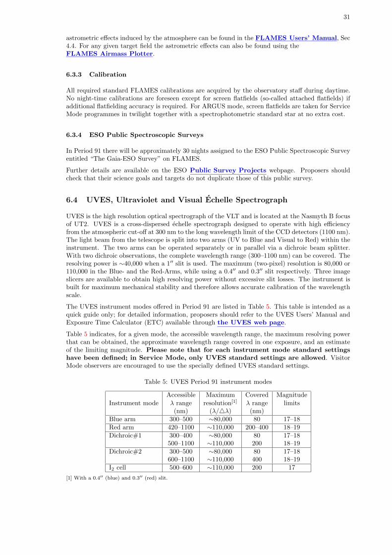
31
astrometric effects induced by the atmosphere can be found in the FLAMES Users’ Manual, Sec4.4. For any given target field the astrometric effects can also be found using theFLAMES Airmass Plotter.
6.3.3 Calibration
All required standard FLAMES calibrations are acquired by the observatory staff during daytime.No night-time calibrations are foreseen except for screen flatfields (so-called attached flatfields) ifadditional flatfielding accuracy is required. For ARGUS mode, screen flatfields are taken for ServiceMode programmes in twilight together with a spectrophotometric standard star at no extra cost.
6.3.4 ESO Public Spectroscopic Surveys
In Period 91 there will be approximately 30 nights assigned to the ESO Public Spectroscopic Surveyentitled “The Gaia-ESO Survey” on FLAMES.
Further details are available on the ESO Public Survey Projects webpage. Proposers shouldcheck that their science goals and targets do not duplicate those of this public survey.
6.4 UVES, Ultraviolet and Visual Echelle Spectrograph
UVES is the high resolution optical spectrograph of the VLT and is located at the Nasmyth B focusof UT2. UVES is a cross-dispersed echelle spectrograph designed to operate with high efficiencyfrom the atmospheric cut-off at 300 nm to the long wavelength limit of the CCD detectors (1100 nm).The light beam from the telescope is split into two arms (UV to Blue and Visual to Red) within theinstrument. The two arms can be operated separately or in parallel via a dichroic beam splitter.With two dichroic observations, the complete wavelength range (300–1100 nm) can be covered. Theresolving power is ∼40,000 when a 1′′ slit is used. The maximum (two-pixel) resolution is 80,000 or110,000 in the Blue- and the Red-Arms, while using a 0.4′′ and 0.3′′ slit respectively. Three imageslicers are available to obtain high resolving power without excessive slit losses. The instrument isbuilt for maximum mechanical stability and therefore allows accurate calibration of the wavelengthscale.
The UVES instrument modes offered in Period 91 are listed in Table 5. This table is intended as aquick guide only; for detailed information, proposers should refer to the UVES Users’ Manual andExposure Time Calculator (ETC) available through the UVES web page.
Table 5 indicates, for a given mode, the accessible wavelength range, the maximum resolving powerthat can be obtained, the approximate wavelength range covered in one exposure, and an estimateof the limiting magnitude. Please note that for each instrument mode standard settingshave been defined; in Service Mode, only UVES standard settings are allowed. VisitorMode observers are encouraged to use the specially defined UVES standard settings.
Table 5: UVES Period 91 instrument modes
Accessible Maximum Covered MagnitudeInstrument mode λ range resolution[1] λ range limits
(nm) (λ/4λ) (nm)Blue arm 300–500 ∼80,000 80 17–18Red arm 420–1100 ∼110,000 200–400 18–19Dichroic#1 300–400 ∼80,000 80 17–18
500–1100 ∼110,000 200 18–19Dichroic#2 300–500 ∼80,000 80 17–18
600–1100 ∼110,000 400 18–19I2 cell 500–600 ∼110,000 200 17
[1] With a 0.4′′ (blue) and 0.3′′ (red) slit.
32
The magnitude limits listed in Table 5 are estimated on the basis of the following conditions:continuum source, 0.7′′ seeing, 1′′ slit, no binning, 3-hour integration, S/N of 10 (per resolutionelement) at the peak of the central order, no moon. They are indicative of the limiting performanceof the instrument only as they depend on the wavelength. UVES proposers should use the ETC fortheir S/N estimates.
Whether or not an image slicer should be used depends on the trade-off between slit losses due toseeing and the reduced transmission (reduction between 20 and 40%) when using an image slicer.The special spectral formats and the reduced sample of the sky spectrum with the image slicer alsohave to be taken into account.
Eight interference filters are offered with the UVES RED arm in Visitor Mode. The purpose ofthese filters is to isolate certain echelle orders to allow the use of the maximum slit length of 30 ′′.The central wavelengths of the filters are chosen to permit observations of the most importantemission lines in extended objects. The filters and their central wavelengths are: Hα (656.6 nm),Hβ (486.1 nm), Oiii (500.7 nm), Oiii (436.3 nm), Nii (575.5 nm), Oi (630.0 nm), Sii (672.4 nm), andHeii (468.6 nm). The peak transmissions of the filters range from 70 to 90%.
In July 2009 the MIT CCD was replaced by an improved version that offers less fringing and higherthroughput redwards of ∼800-nm. See the UVES news page for details. Proposals for the veryred end of the UVES range (around 1 micron) should consider whether CRIRES would be bettersuited. A detailed comparison of UVES and CRIRES performance around 1 micron is given on theCRIRES news page.
For more detailed information on instrument setups and performance estimates the user is referredto the UVES web page.
6.5 XSHOOTER: multi band, medium resolution echelle spectrograph
XSHOOTER – the first VLT second generation instrument – is the UV-Visual-NIR medium resolu-tion spectrograph mounted at the UT2 Cassegrain focus. Three arms, each with optimized optics,dispersive elements and detectors, allow high efficiency observation simultaneously in the wavelengthrange 300-2480 nm.
Each arm is an independent cross-dispersed echelle spectrograph complete with its own shutterand/or slit mask. The incoming light is split into the three different spectrographs/arms through 2dichroics that have cut-off wavelengths at 5595A (for the separation of UVB-VIS light) and 10240A(for the separation of the VIS-NIR light). Three piezo-controlled mirrors, located in front of eacharm, guarantee that the optical path remains aligned against instrument flexure and corrected fordifferential atmospheric refraction between the telescope guiding wavelength and each arm centralwavelength.
The two pairs of ADC prisms in the optical path of the UVB and VIS arms, which normally com-pensate for the atmospheric dispersion are currently disabled. Because their mechanical system isdamaged and are therefore not reliable anymore, they have been fixed in their non deviation positionsince August 1st, 2012. Data obtained in this configuration can be reduced by the pipeline withoutsignificant degradation. Use of ADCs in the future depends on the result of further investigationsand possible intervention.
Users should check the XSHOOTER News webpage to follow the status of the ADCs. The lastversion of the user manual provides plots for helping the observation preparation with XSHOOTERwithout ADCs.
Users are recommended to carry out observations at the parallactic angle whenever possible or totake special care on the airmass constraint to avoid flux loss.
Two instrument modes are offered:
• slit spectroscopy (SLT) with a selection of different slit widths for each arm and a fixed lengthof 11 arcsec. In Period 91, the offered slits have widths of
– for the UVB arm: 0.5, 0.8, 1.0, 1.3, 1.6, 5.0 arcsec,

33
– for the VIS arm: 0.4, 0.7, 0.9, 1.2, 1.5, 5.0 arcsec,
– for the NIR arm: 0.4, 0.6, 0.6 + K-band blocking filter, 0.9 , 0.9 + K-band blocking filter,1.2, 5.0 arcsec, a blind position.
• IFU spectroscopy, which allows observations of a 1.8 × 4 arcsec2 field reformatted to a 0.6 ×12 arcsec long-slit.
The spectral format is fixed. The orders in each detector are highly curved and the sky/arc lineswithin each order are highly tilted.
The background between the OH lines in the J and H bands is strongly affected by photons scatteredfrom the very bright K-band orders. In order to allow sky limited performance in the J and H bands,two new slits of width 0.6” and 0.9” combined with a K-band blocking filter were installed on the slitwheel of the NIR arm in July 2011. One of these new slits replaced the 1.5” slit, which is thereforenot offered anymore. These new slits allow for a reduction of the overall background by a factor of3 to 4 in the H and J bands.
The minimum DIT in the NIR arm is 0.66s. The 1800s DIT in the NIR arm is only offered infull-night VM as it introduces severe remnants. However, the use of 1800 s DIT in the NIR armwith the 0.6 or 0.9′′ slit combined with a K-band blocking filter could be possibly granted also inSM observations provided the strategy is very well-justified through a waiver request at Phase 2.
We encourage the users to read the XSHOOTER NIR readout mode description. about theNIR non destructive readout mode and its different regimes.
More detailed information regarding the instrument are provided in the XSHOOTER page.
6.6 VIMOS, VIsible Multi-Object Spectrograph
VIMOS is a multi-mode, wide-field optical instrument attached at the Nasmyth B focus of Melipal(UT3). VIMOS allows imaging (IMG) and multi-object spectroscopy (MOS) at low- (R ∼ 200) tomedium-resolution (R ∼ 2500) over a field of view (FOV) composed of four quadrants, each 7′× 8′,separated by 2′ gaps. MOS masks, which are prepared with the Mask Manufacturing Unit (MMU)on Paranal, allow considerable freedom in the positioning, shape, and orientation of the slits. Themaximum number of slits that can be typically accommodated in the VIMOS FOV is up to 750 atlow resolution, and up to 150 at higher resolution. The actual number of slits will depend on themultiplex used, target density and their distribution in the field of view.
Important notes:
• The VIMOS upgrade project continues with the refurbishment of the focus unit to permitproper focussing at all temperatures in IFU mode. Details on the scope of the upgrade project,expected performance, validity of pre-imaging observations, and availability of the instrumentare given in the News section of the VIMOS web pages.
• Starting from P91, a new Pre-Image-Less MOS (PILMOS) mode is offered, in which a userprovided catalogue with accurate target coordinates (≤ ±0.2′′)) can be used to design masks.Slit orientation must be N-S.
• This period we have relaxed the requirement on MOS slit orientation: if target declination iswithin −45◦ < δ < −5◦, slits can also be oriented E-W and the observations executed within±3 h from meridian. In this case a pre-imaging run must be requested.
• Due to existing commitments no Large Programmes using VIMOS can be submitted inPeriod 91.
VIMOS is equipped with an integral field unit (IFU) with 6400 microlenses coupled to fibres and achoice of two spatial samplings (magnifications): 0.67′′ per fibre or 0.33′′ per fibre. With the lowerspectral resolution settings, the FOV of the IFU is 54′′×54′′ (using the 0.67′′ magnification), or27′′×27′′ (using the 0.33′′ magnification). A quarter of these fields are covered at intermediate tohigher spectral resolutions.
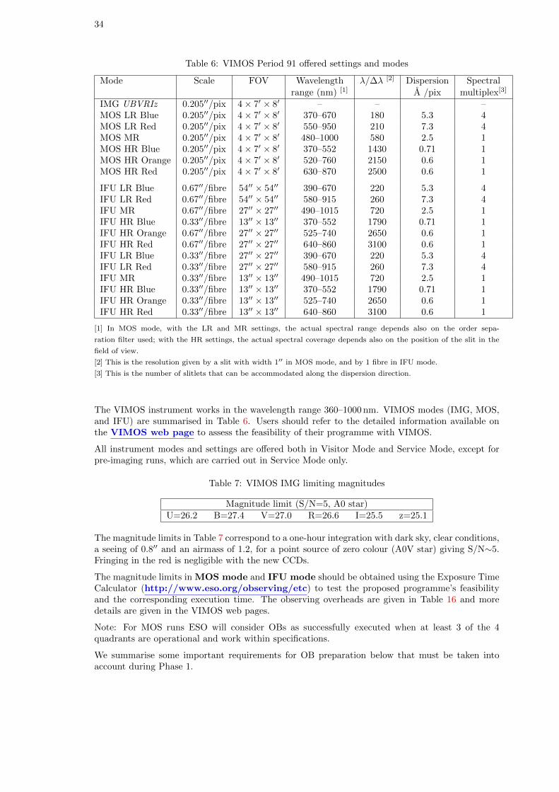
34
Table 6: VIMOS Period 91 offered settings and modes
Mode Scale FOV Wavelength λ/∆λ [2] Dispersion Spectralrange (nm) [1] A /pix multiplex[3]
IMG UBVRIz 0.205′′/pix 4× 7′ × 8′ – – –MOS LR Blue 0.205′′/pix 4× 7′ × 8′ 370–670 180 5.3 4MOS LR Red 0.205′′/pix 4× 7′ × 8′ 550–950 210 7.3 4MOS MR 0.205′′/pix 4× 7′ × 8′ 480–1000 580 2.5 1MOS HR Blue 0.205′′/pix 4× 7′ × 8′ 370–552 1430 0.71 1MOS HR Orange 0.205′′/pix 4× 7′ × 8′ 520–760 2150 0.6 1MOS HR Red 0.205′′/pix 4× 7′ × 8′ 630–870 2500 0.6 1
IFU LR Blue 0.67′′/fibre 54′′ × 54′′ 390–670 220 5.3 4IFU LR Red 0.67′′/fibre 54′′ × 54′′ 580–915 260 7.3 4IFU MR 0.67′′/fibre 27′′ × 27′′ 490–1015 720 2.5 1IFU HR Blue 0.33′′/fibre 13′′ × 13′′ 370–552 1790 0.71 1IFU HR Orange 0.67′′/fibre 27′′ × 27′′ 525–740 2650 0.6 1IFU HR Red 0.67′′/fibre 27′′ × 27′′ 640–860 3100 0.6 1IFU LR Blue 0.33′′/fibre 27′′ × 27′′ 390–670 220 5.3 4IFU LR Red 0.33′′/fibre 27′′ × 27′′ 580–915 260 7.3 4IFU MR 0.33′′/fibre 13′′ × 13′′ 490–1015 720 2.5 1IFU HR Blue 0.33′′/fibre 13′′ × 13′′ 370–552 1790 0.71 1IFU HR Orange 0.33′′/fibre 13′′ × 13′′ 525–740 2650 0.6 1IFU HR Red 0.33′′/fibre 13′′ × 13′′ 640–860 3100 0.6 1
[1] In MOS mode, with the LR and MR settings, the actual spectral range depends also on the order sepa-
ration filter used; with the HR settings, the actual spectral coverage depends also on the position of the slit in the
field of view.
[2] This is the resolution given by a slit with width 1′′ in MOS mode, and by 1 fibre in IFU mode.
[3] This is the number of slitlets that can be accommodated along the dispersion direction.
The VIMOS instrument works in the wavelength range 360–1000 nm. VIMOS modes (IMG, MOS,and IFU) are summarised in Table 6. Users should refer to the detailed information available onthe VIMOS web page to assess the feasibility of their programme with VIMOS.
All instrument modes and settings are offered both in Visitor Mode and Service Mode, except forpre-imaging runs, which are carried out in Service Mode only.
Table 7: VIMOS IMG limiting magnitudes
Magnitude limit (S/N=5, A0 star)U=26.2 B=27.4 V=27.0 R=26.6 I=25.5 z=25.1
The magnitude limits in Table 7 correspond to a one-hour integration with dark sky, clear conditions,a seeing of 0.8′′ and an airmass of 1.2, for a point source of zero colour (A0V star) giving S/N∼5.Fringing in the red is negligible with the new CCDs.
The magnitude limits in MOS mode and IFU mode should be obtained using the Exposure TimeCalculator (http://www.eso.org/observing/etc) to test the proposed programme’s feasibilityand the corresponding execution time. The observing overheads are given in Table 16 and moredetails are given in the VIMOS web pages.
Note: For MOS runs ESO will consider OBs as successfully executed when at least 3 of the 4quadrants are operational and work within specifications.
We summarise some important requirements for OB preparation below that must be taken intoaccount during Phase 1.
35
6.6.1 VIMOS Observation Requirements: IMG
Offsets greater than 30′′ are not allowed during OB execution as they often cause the loss of theguide star, resulting in large operational overheads. If an offset pattern with a greater amplitude isneeded, users should use separate OBs at each offset position. The increased overhead time due tothis feature must be accounted for when estimating the total time needed for VIMOS imaging runs.
In IMG mode, filter exchanges are allowed within an OB. Overheads for filter exchanges need to beincluded using the estimate given in Table 16.
6.6.2 VIMOS observation requirements: MOS and pre-imaging
MOS observations are performed with machine-cut masks that have to be prepared well in advance.ESO provides a software package (vmmps) for slit definition and positioning for Phase 2 preparation(equivalent to FIMS for the FORS2 instrument). The user can define rectangular slits of width widerthan 0.6′′ and length up to 30′′. Inclined slits can be defined.
The change of CCDs that took place during P85 (June-July 2010) invalidated all pre-imaging datataken before August 1, 2010.
Pre-imaging is recommended for subsequent spectroscopic (MOS) follow-ups, even when targetscome from a pre-defined catalogue, and must be carried out with the R filter. Pre-imaging is donein Service Mode (this also applies for MOS Visitor runs); separate runs must be requested forpre-imaging in the Phase 1 proposal and associated overheads have to be taken into accountby the users. Pre-imaging runs are carried out typically two months in advance of the spectroscopicfollow-up. Masks need to be prepared as soon as possible after the pre-imaging has been completedand submitted according to Phase 2 procedures.
The observations taken as part of a pure imaging run (without the pre-imaging flag set) cannotbe used for the subsequent mask preparation due to the lack of the controlled mask-to-ccd trans-formation keywords in the headers. Even in the case when imaging data have been obtained withVIMOS, if the user wishes to use a VIMOS image to design the mask then a short pre-imaging runis mandatory.
Starting from Period 90 we are offering a Pre-Image-Less MOS mode, PILMOS, that can be used formask preparation when the user has a pre-defined catalogue of targets with good quality astrometry(relative positioning accuracy better than ±0.′′2). See manual for details.
VIMOS is not equipped with an Atmospheric Dispersion Corrector. In order to minimise slit losses,MOS observations and their pre-imaging are taken at a pre-defined position angles on sky, withslits oriented either N-S or E-W. For N-S orientation the observations are executed within 2 h of themeridian. If target declination is −45◦ < δ < −5◦, slits can be oriented E-W and the observationswill be executed within 3 h of the meridian. Special requirements for different field orientationsshould be clearly stated in the proposals.
Due to the recently commisioned automatic flexure compensation system (AFC) attached arcs andflats are no longer mandatory in MOS mode. Nevertheless, we recommend that users still attach3 flats and 1 arc if they want the maximum wavelength precision and flat fielding accuracy in anyof the high resolution grism. This is specially true for the new VPH HR blue grism, because thenumber of sky and arc lines is rather limited in the blue. The corresponding overheads need to betaken into account at Phase 1 and can be estimated using Table 16.
In MOS mode only one filter+grism combination per OB is permitted (the only filter exchangeallowed is the one between acquisition and science template). Users who want to observe the sametargets with different filter+grism combinations are requested to submit separate OBs for differentfilter+grism combinations and to consider the respective overheads.
6.6.3 MOS Observations in Visitor Mode
Because MOS observations should be carried out within 2 h of the meridian, targets must be uni-formly distributed in RA for the night(s) of the Visitor Mode observations. If this is not possible
36
users should apply for Service Mode observations. A maximum number of 7 visitor masks (perquadrant) will be made available each night, with only (3 masks) per quadrant for half-night runs.
Users should submit OBs for mask preparation well before their observing run, so that masks canbe manufactured before they arrive. Visitor Mode (VM) observers who wish to use VIMOS in MOSmode are required to submit part of their OBs at least 3 weeks before the first night of the VM run.Exceptionally, limited additional support is guaranteed for mask preparation on the mountain, upto 3 sets of masks per night, to be prepared at least 48 h in advance.
6.6.4 VIMOS Observation Requirements in IFU Mode
In IFU mode instrumental flexures introduce flatfield residuals and wavelength calibration offsetsif the calibration data and the science data are taken at very different rotator angles. In orderto minimise these effects attached night-time arcs and screen flats are mandatory in IFU mode forall settings. The corresponding overheads need to be taken into account at Phase 1 and can beestimated using Table 16.
Only one filter+grism combination per OB is permitted in IFU mode. Users who want to observethe same targets with different filter+grism combinations are requested to submit separate OBs fordifferent filter+grism combinations and to consider the respective overheads.
6.7 VISIR, VLT Imager and Spectrometer for mid Infra Red
VISIR is the mid-infrared imager and spectrometer at the Cassegrain focus of UT3. It operates inthe wavelength ranges 8− 13µm and 17− 24µm.
Important note: VISIR has undergone a major intervention during Period 89. The upgradeproject included the replacement of the old DRS detector with the new Aquarius arrays. Moreover,it included an intervention on the low-resolution spectroscopy mode in order to provide completeN -band coverage in a single shot.
Details are available on the ESO VISIR instrument page. The intervention, recommissioningand a performance validation phase are planned to be completed at the start of Period 90, afterwhich VISIR will resume regular operations.
6.7.1 Imaging Modes
In Period 91 the imager with a 1024×1024 detector array is offered with image scales of 0.′′045/pixel(SF) and 0.′′0762/pixel (IF). The filters available are: PAH1, ArIII, SIV 1, SIV, SIV 2, PAH2, SiC,PAH2 2, NeII 1, NeII, NeII 2, Q1, Q2, Q3, B8.7, B9.7, B10.7, B11.7, B12.4, J7.9, J8.9, J9.8 andJ12.2.
The offered sensitivities correspond to the old detector. They range between about 4 and 20 mJy10σ/1 h in the N band and between about 50 and 150 mJy 10σ/1 h in the Q band, depending onthe selected filter and image scale.The Burst read out mode is offered in Visitor mode only for the imager. It allows one to saveevery single DIT of the observation providing a time resolution of few tens milliseconds, dependingon the instrument setup.Please refer to the VISIR Web pages for further details.
6.7.2 Spectroscopy Modes
The spectrometer is offered for N and Q band spectroscopy in the following modes:
• Low resolution (LR) mode with a resolution of R ≈ 225 for a 0.′′4 slit width in one setting thatcovers the full N band, with sensitivity about 50 mJy 10σ/1 h.

37
• Medium Resolution (MR) mode with a resolution of up to R ≈ 3600 in the N band for thewavelength ranges of 7.4 − 9.4µm and 10.2 − 13.0µm , and with a resolution of R ≈ 1800 inthe Q band for the wavelength ranges of 17.1− 19.0µm and 19.9− 20.3µm . Sensitivities arebetween about 200 and 2000 mJy 10σ/1 h, depending on the spectral range.
• High resolution (HR) mode with a resolution of R ≈ 15000 − 30000 at wavelengths near the[H2 S4], [NeII], [H2 S1] lines in longslit mode, and a wider range of wavelengths including the[H2 S3], [H2 S2], [ARIII], [SIV], [CoII], [ClIV], [NeII], [CoIII], [CoI], [PIII], [FeII], [NiII], [SIII],[NaIV], HD(0,0) R(9),R(10) lines in cross-dispersed mode. Sensitivities are between about2 000 and 10 000 mJy 10σ/1 h, depending on the spectral range and mode.
The VISIR spectrometer observing modes have the following restrictions:
• Acquisition is possible with the spectro-imager for targets brighter than 50 mJy using the[ArIII] or [NeII]
filter. Please contact [email protected] for fainter targets.
• Absorption line spectroscopy is untested and flatfielding problems may be anticipated.
The slits cover a range of 0.′′4 – 1.′′0 in width and 40′′ in length. The image scale in the spatialdirection is 0.′′0762/pixel. Please refer to the VISIR Web pages for further details. Note thatsensitivity limits in the MIR vary strongly with wavelength due to the atmosphere.
6.7.3 Calibrations
In imaging, one photometric standard star observation will be provided per science target with nocost for the user. In low-resolution spectroscopy, the Observatory will provide spectrophotometricobservations of a telluric standard star. Such a calibration measurement will be performed at leastonce per night, per instrument configuration. The Observatory does not provide standard starcalibrations for VISIR medium- and high-resolution spectroscopy. If MR, HR or any additionalstandard star observations are required, the user has to supply his/her own calibration OBs usingthe corresponding calibration templates. The observing time needed to execute this calibration ischarged to the programme.
6.7.4 Exposure Time Calculator
The users are requested to use the ETC (http://www.eso.org/observing/etc) in order to testthe feasibility of their programme and estimate the corresponding execution time. The correspondingobserving overheads are given in Table 16. For more details please consult the VISIR User Manualavailable at http://www.eso.org/instruments/visir/doc/.
6.8 HAWK-I, High Acuity Wide-field K-band Imager
HAWK-I is a near-infrared (0.85–2.5µm) wide-field imager installed at the Nasmyth A focus of UT4.
The instrument is cryogenic (120 K, detectors at 75 K) and has a fully reflective design. The lightpasses four mirrors and two filter wheels before hitting a mosaic of four Hawaii 2RG 2048×2048pixels detectors. The final f-ratio is f/4.36 (1′′ on the sky corresponds to 169.4µm on the detector).
As of Period 83, proposers can request the Rapid Response Mode (RRM) to trigger HAWK-Iobservations. For details on RRM policies, please see Section 11.3.1.
Important note: Due to possible future changes, Large Programmes using HAWK-I will not beaccepted in Period 91.
Online information on HAWK-I can be found via the instrument web page.
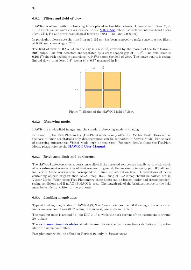
38
6.8.1 Filters and field of view
HAWK-I is offered with 10 observing filters placed in two filter wheels: 4 broad-band filters Y, J,H, Ks (with transmission curves identical to the VIRCAM filters), as well as 6 narrow-band filters(Brγ, CH4, H2 and three cosmological filters at 0.984 1.061, and 2.090µm).
In particular, please note that the filter at 1.187µm has been removed to make space to a new filter,at 0.984µm since August 2012.
The field of view of HAWK-I on the sky is 7.5′×7.5′, covered by the mosaic of the four Hawaii-2RG chips. The four detectors are separated by a cross-shaped gap of ∼ 15′′. The pixel scale is0.1064′′/pix with negligible distortions (< 0.3%) across the field of view. The image quality is seeinglimited down to at least 0.4′′ seeing (i.e. 0.3′′ measured in K).
217”15”
7.5’
Figure 7: Sketch of the HAWK-I field of view.
6.8.2 Observing modes
HAWK-I is a wide-field imager and the standard observing mode is imaging.
In Period 91, the Fast Photometry (FastPhot) mode is only offered in Visitor Mode. However, inthe case of lunar occultations only disappearances can be supported in Service Mode. In the caseof observing appearances, Visitor Mode must be requested. For more details about the FastPhotMode, please refer to the HAWK-I User Manual.
6.8.3 Brightness limit and persistence
The HAWK-I detectors show a persistence effect if the observed sources are heavily saturated, whichaffects subsequent observations of faint sources. In general, the maximum intensity per DIT allowedfor Service Mode observations correspond to 5 time the saturation level. Observations of fieldscontaining objects brighter than Ks=8.1 mag, H=9.1 mag or J=8.8 mag should be carried out inVisitor Mode. When using Fast Photometry these limits can be broken under bad (recommended)seeing conditions and if noAO (BadAO) is used. The magnitude of the brightest source in the fieldmust be explicitly written in the proposal.
6.8.4 Limiting magnitudes
Typical limiting magnitudes of HAWK-I (S/N of 5 on a point source, 3600 s integration on source)under average conditions (0.8′′ seeing, 1.2 airmass) are given in Table 8.
The read-out noise is around 5 e− for DIT > 15 s, while the dark current of the instrument is around2 e−/pix/s.
The exposure time calculator should be used for detailed exposure time calculations, in partic-ular for narrow-band filters,
Fast photometry will be offered in Period 91 only in Visitor mode.
39
Table 8: HAWK-I limiting magnitude examples
Filter Limiting mag Limiting mag[Vega] [AB]
J 23.9 24.8H 22.5 23.9Ks 22.3 24.2
6.9 NACO (NAOS+CONICA)
NACO provides adaptive optics-assisted imaging, polarimetry, spectroscopy, and coronagraphy inthe 1–5µm range and is installed at the Nasmyth B focus of UT4.
Important note: Large Programme proposals using NACO will not be accepted in Period 91 dueto the planned installation of MUSE in the course of 2013.
Details of the instrument, tools and observing modes can be found through the NACO Web page.
6.9.1 Adaptive optics correction with Natural and Laser Guide Stars
NAOS, the adaptive optics front-end, has been designed to work with Natural Guide Stars (NGS)and moderately extended objects. It is equipped with one infrared and one visual wavefront sensor.For a point-like reference source with a visual brightness of V=12, NAOS can provide Strehl ratiosas high as 50% (on axis) in the K band in optimal weather conditions. A more realistic value is 40%in good conditions. It can provide partial correction for targets as faint as V=17. Users should usethe preparation software and the NACO ETC for the preparation of their proposals.
NAOS can also be used with the LGS (LGS mode, see Section 4.2.3 for additional details). Twomodes are possible:
• with a tip-tilt star (TTS), of V magnitude in the range 12–18 and with a maximum angularseparation of 55′′ from the science target. However, the performance of the adaptive opticscorrection decreases with increasing angular separation from the science targets. Finally, thechoice of the TTS imposes some constraints on the field orientation. The name of the TTSmust be specified in the target list of the Phase 1 proposal using the ESOFORM proposaltemplate;
• without a tip-tilt star, also called seeing enhancer mode. The name of the TTS must be leftblank in the target list of the Phase 1 proposal.
It is compulsory to provide the magnitude of the star and the bandpass in which the magnitude isgiven for both NGS and LGS with TTS. Observations in LGS mode require either clear (CLR) orphotometric (PHO) conditions: the transparency constraint must be set accordingly in the proposal.
In addition, LGS without TTS (seeing enhancer mode) must require seeing conditions better than0.8′′. Separate runs should be specified in the proposal form for observations using a NGS, on theone hand, and for LGS observations, on the other hand.
The LGS mode of NACO is offered in Service and Visitor Mode.
Note that PARSEC, the laser currently used by the Laser Guide Star Facility will be decommis-sioned during Period 90. It will be replaced by a prototype of the laser used by the coming AOF.Its commissioning is expected to be completed before the start of Period 91.
6.9.2 Offered modes
CONICA is the imager and spectrograph which is fed by NAOS. CONICA offers a large range ofmodes, filters, grisms and masks. Only the main characteristics of each mode are described here.Details can be found in the NACO Users’ Manual.
40
For low Strehl ratios (a few percent or less), users should carefully weigh the advantages of usingNACO over other IR instruments such as HAWK-I, which generally have larger fields of view, lowerbackgrounds and higher throughputs.
A summary of the offered modes is given in Table 9.
Table 9: NaCo modes in Period 91
Imaging SM and VM All filters except MpImaging + cube SM and VM Limited setups
noAO (Open loop Imaging + cube) SM and VM Limited setupsSDI+ SM and VM Replaces SDI
Lyot Coronagraphy SM and VM C 0.7, C 1.4 (all cameras),C 0.7 sep 10 (not S13 camera),
field and pupil trackingPhase-Mask Coronagraphy (4QPM) SM and VM Optimized for H and K
field and pupil trackingAPP Coronography SM and VM Simple Imaging, L′ and NB 4.05 only
SAM VM Includes pupil tracking and cube modeSAM+Pol VM SAM with Woll 00
Polarimetry SM and VM Woll 00, retarder plate onlyPolarimetry+cube SM and VM Woll 00, retarder plate only
Grism Spectroscopy SM and VM All modes except pupil trackingGrism Spectroscopy + APP VM All modes except pupil tracking,
no pipeline supportPrism Spectroscopy VM Limited setups
LGS SM and VM See Section 4.2.3LGS/SE SM and VM See Section 4.2.3
Pupil Tracking SM and VM Simple Imaging, SDI+, APP,Lyot and Phase Masks (4QPM)
Visitor Mode must be requested for programmes requiring special calibrations, i.e. calibrations notdefined in the NACO Calibration Plan (see Section 6.9.3).
SM proposals require a detailed justification for the need for SM and will be considered on a case-by-case basis as part of the technical feasibility evaluation of the Observatory. See Section 6.9.3 fordetails.
Imaging, Polarimetric and Coronagraphic Modes Imaging, polarimetry and coronagraphycan be done with a variety of filters, pixel scales and fields of view (Table 10).
Table 10: NACO pixel scales and fields of view
Wavelength range Scale (mas/pix)1 FOV (arcsec)SW filters2 54.3 56×56SW filters 27.0 28×28SW filters 13.3 14×14
NB 4.05,NB 3.74 54.7 56×56NB 4.05,NB 3.74, L′ 27.1 28×28
[1] For reference: the diffraction limited FWHM of a point source imaged with an 8m telescope are J(32 mas),
H(42 mas), Ks(56 mas), L′(98 mas), and M′(123 mas).
[2] Short Wavelength (SW) filters refer to filters with wavelengths shorter than 2.5µm.
Polarimetry observations are carried-out using the retarder plate and the Wollaston 00. J-bandpolarimetry observations are not possible because of the location of the J filter in the same wheelas the Wollaston.
Coronagraphy can be performed with a portfolio of focal-plane masks. NACO indeed offers a choice
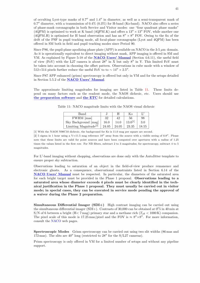
41
of occulting Lyot-type masks of 0.7′′ and 1.4′′ in diameter, as well as a semi-transparent mask of0.7′′ diameter, with a transmission of 0.4% (0.3%) for H-band (Ks-band). NACO also offers a seriesof phase-mask coronagraphs in both Service and Visitor modes: one “four quadrant phase masks”(4QPM) is optimised to work at K band (4QPM K) and offers a 13′′× 13′′ FOV, while another one(4QPM H) is optimised for H band observation and has an 8′′ × 8′′ FOV. Owing to the fix of thedrift of the PSF in pupil tracking mode, all focal-plane coronagraphs (Lyot and 4QPM) has beenoffered in SM both in field and pupil tracking modes since Period 90.
Since P86, the pupil-plane apodizing phase plate (APP) is available on NACO in the 3-5 µm domain.As it is operationally equivalent to direct imaging without mask, APP imaging is offered in SM andVM. As explained by Figure 5-18 of the NACO Users’ Manual (Section 4.6.11), the useful fieldof view (FoV) with the L27 camera is about 28′′ in X but only 8′′ in Y. This limited FoV mustbe taken into account in choosing the offset pattern. Observations in cube mode with a window of512×514 pixels further reduce the useful FoV to to ∼ 14′′ × 2.5′′.
Since P87 APP enhanced (grism) spectroscopy is offered but only in VM and for the setups detailedin Section 5.5.2 of the NACO Users’ Manual.
The approximate limiting magnitudes for imaging are listed in Table 11. These limits de-pend on many factors such as the readout mode, the NAOS dichroic, etc. Users should usethe preparation software and the ETC for detailed calculations.
Table 11: NACO magnitude limits with the NAOS visual dichroic
Band J H Ks L′
FWHM [mas] 32 42 56 98Sky Background [mag] 16.0 14.0 13.0[1] 3.0Limiting Magnitude[2] 24.05 24.05 23.35 18.55
[1] With the NAOS N90C10 dichroic, the background for Ks is 11.0 mag per square arc second.
[2] 5 sigma in 1 hour using a V=11.5 mag reference 10′′ away from the source with a visible seeing of 0.8′′. Please
note that these limits are valid for point sources and have been computed over apertures with a radius of 1.25
times the values listed in the first row. For NB filters, subtract 2 to 3 magnitudes; for spectroscopy, subtract 4 to 5
magnitudes.
For L′-band imaging without chopping, observations are done only with the AutoJitter template toensure proper sky subtraction.
Observations leading to saturation of an object in the field-of-view produce remanence andelectronic ghosts. As a consequence, observational constraints listed in Section 6.14 of theNACO Users’ Manual must be respected. In particular, the diameters of the saturated areafor each bright target must be provided in the Phase 1 proposal. Observations leading to asaturated area whose diameter exceeds 4 pixels must be clearly identified in the tech-nical justification in the Phase 1 proposal. They must usually be carried out in visitormode; in special cases, they can be executed in service mode pending the approval ofa waiver during the Phase 2 preparation.
Simultaneous Differential Imager (SDI+) High contrast imaging can be carried out usingthe simultaneous differential imager (SDI+). Contrasts of 30,000 can be obtained at 0.′′5 in 40 min atS/N of 6 between a bright (H< 7 mag) primary star and a methane rich (Teff < 1000 K) companion.The pixel scale of this mode is 17.25 mas/pixel and the FOV is ≈ 8′′×8′′. For more information,consult the NACO web pages.
Spectroscopic Modes Grism spectroscopy can be carried out using two slit widths (86 mas and172 mas). The slits are 40′′ long (restricted to 28′′ for the S/L27 cameras).
Prism spectroscopy is only offered in VM for a limited number of setups and without any pipelinesupport.
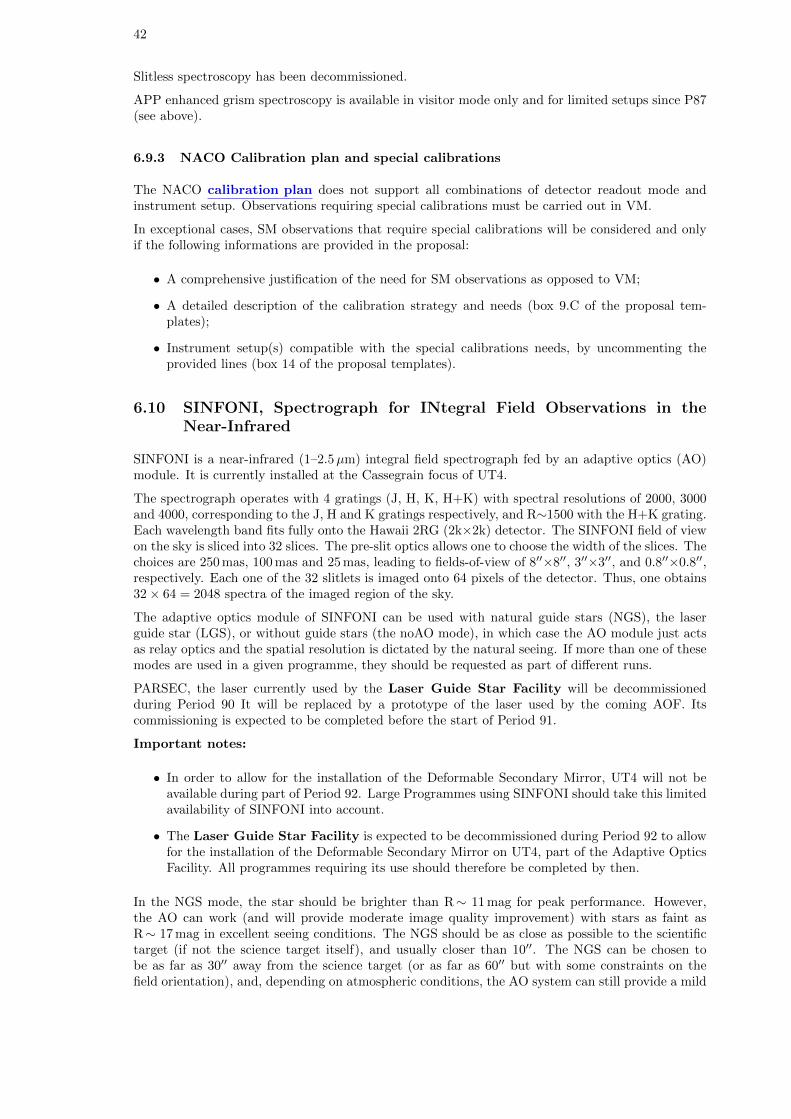
42
Slitless spectroscopy has been decommissioned.
APP enhanced grism spectroscopy is available in visitor mode only and for limited setups since P87(see above).
6.9.3 NACO Calibration plan and special calibrations
The NACO calibration plan does not support all combinations of detector readout mode andinstrument setup. Observations requiring special calibrations must be carried out in VM.
In exceptional cases, SM observations that require special calibrations will be considered and onlyif the following informations are provided in the proposal:
• A comprehensive justification of the need for SM observations as opposed to VM;
• A detailed description of the calibration strategy and needs (box 9.C of the proposal tem-plates);
• Instrument setup(s) compatible with the special calibrations needs, by uncommenting theprovided lines (box 14 of the proposal templates).
6.10 SINFONI, Spectrograph for INtegral Field Observations in theNear-Infrared
SINFONI is a near-infrared (1–2.5µm) integral field spectrograph fed by an adaptive optics (AO)module. It is currently installed at the Cassegrain focus of UT4.
The spectrograph operates with 4 gratings (J, H, K, H+K) with spectral resolutions of 2000, 3000and 4000, corresponding to the J, H and K gratings respectively, and R∼1500 with the H+K grating.Each wavelength band fits fully onto the Hawaii 2RG (2k×2k) detector. The SINFONI field of viewon the sky is sliced into 32 slices. The pre-slit optics allows one to choose the width of the slices. Thechoices are 250 mas, 100 mas and 25 mas, leading to fields-of-view of 8′′×8′′, 3′′×3′′, and 0.8′′×0.8′′,respectively. Each one of the 32 slitlets is imaged onto 64 pixels of the detector. Thus, one obtains32× 64 = 2048 spectra of the imaged region of the sky.
The adaptive optics module of SINFONI can be used with natural guide stars (NGS), the laserguide star (LGS), or without guide stars (the noAO mode), in which case the AO module just actsas relay optics and the spatial resolution is dictated by the natural seeing. If more than one of thesemodes are used in a given programme, they should be requested as part of different runs.
PARSEC, the laser currently used by the Laser Guide Star Facility will be decommissionedduring Period 90 It will be replaced by a prototype of the laser used by the coming AOF. Itscommissioning is expected to be completed before the start of Period 91.
Important notes:
• In order to allow for the installation of the Deformable Secondary Mirror, UT4 will not beavailable during part of Period 92. Large Programmes using SINFONI should take this limitedavailability of SINFONI into account.
• The Laser Guide Star Facility is expected to be decommissioned during Period 92 to allowfor the installation of the Deformable Secondary Mirror on UT4, part of the Adaptive OpticsFacility. All programmes requiring its use should therefore be completed by then.
In the NGS mode, the star should be brighter than R∼ 11 mag for peak performance. However,the AO can work (and will provide moderate image quality improvement) with stars as faint asR∼ 17 mag in excellent seeing conditions. The NGS should be as close as possible to the scientifictarget (if not the science target itself), and usually closer than 10′′. The NGS can be chosen tobe as far as 30′′ away from the science target (or as far as 60′′ but with some constraints on thefield orientation), and, depending on atmospheric conditions, the AO system can still provide a mild
43
improvement in the encircled energy. The name of the NGS must be specified in the target list ofthe Phase 1 proposal using the ESOFORM proposal template.
The LGS mode (see Section 4.2.3 for additional details) can be used with or without a tip-tilt star.In Period 91 the LGS mode of SINFONI is offered in Service and Visitor Mode.
If a tip-tilt star (TTS) is used, it should be in the R magnitude range 12–18 and can be as far awayas 60′′ from the science target. However, performance decreases with increasing distance, and thereare some constraints on the field orientation. The name of the TTS must be specified in the targetlist of the Phase 1 proposal using the ESOFORM proposal template.
The LGS mode without a tip-tilt star (the so-called seeing-enhancer mode) is also offered. Usersrequesting this mode must specify CLR or better for the transparency, and a seeing better than0.8′′ in their Phase 1 application. In the target list of the Phase 1 proposal using the ESOFORMproposal template, the TTS name should be left blank. Since Period 87, users of this mode requiringobservation of a PSF calibrator associated with a science target must make use of the template’SINFONI ifs cal GenericOffset’, that allows one to take the PSF calibrations data within the sameOB as the science data (please see the SINFONI User Manual for details). For the observationof the PSF calibrator sufficient time must be requested in the proposal.
The fast acquisition template must be used only in case of acquisition of bright targets, whichwould saturate the detector in closed loop with the large scale. Excellent astrometry is required forthis acquisition mode.
As of Period 87, proposers can request the Rapid Response Mode (RRM) to trigger SINFONIobservations. This mode is offered with the NGS and noAO modes of SINFONI. For details onRRM policies, please see Section 11.3.1.
Pre-Imaging runs can also be proposed with SINFONI. Such observations are typically dedicated totest the feasibility of a specific science programme (e.g. faint target, difficult acquisition).
Further details can be found on the SINFONI instrument web pages.
6.10.1 Instrument Performance
Table 12 gives the limiting magnitudes (S/N of 5) for continuum sources integrated over the typicalsize of the point-spread function in one hour of integration time.
Table 12: SINFONI fields of view and limiting magnitudes
Field of View Spatial Scale Mode Limiting Magnitudes (continuum)8′′× 8′′ 125× 250 mas noAO J=20.2, H=19.9, K=17.9, H+K=19.63′′× 3′′ 50× 100 mas NGS J=19.4, H=19.6, K=18.8, H+K=19.80.8′′× 0.8′′ 12.5× 25 mas NGS J=17.8, H=18.7, K=18.3, H+K=19.2
These values were calculated for a visual seeing of 0.8′′ which would provide infrared seeing valuesof 0.67′′, 0.63′′, 0.59′′ and 0.61′′ at the central wavelength of the J, H, K and H+K gratings,respectively. For the closed loop adaptive optics observations with natural guide stars (NGS) wehave assumed a guide star at a distance of 10′′ with a photometric brightness of R = 12 and B−R =1.5 magnitudes. We encourage the use of the exposure time calculator for more detailed estimates(http://www.eso.org/observing/etc).
6.10.2 Brightness Limits
To avoid saturation of the detector and detector persistence, which affects subsequent observationsof faint sources, no objects with J, H, K magnitudes < 6 mag must be visible in a field of view of15′′ around the AO guide star and/or the science target. However, if fast acquisition is used,the limits are brighter by 1 and 2 magnitudes for 0.′′1/pix and 0.′′025/pix respectively.
To exclude any risk of artefacts produced by detector persistence, in all templates DITs mustalways be selected such that intensities are at most 8 000 for K, 7 000 for H and H+K and 6 000 for
44
J ADUs/DIT over the entire spectrum.
6.10.3 Sky Subtraction
The user should note that sky offset fields are mandatory for observations in the 25 and 100 masscales. The corresponding overheads have to be taken into account when estimating the requiredtime for an observing run. Typically, 50% (or 33%) of the observing time is spent on sky if NDITSky
= NDITTarget (or NDITSky = 1/2 NDITTarget).
6.10.4 Calibrations
Observations of telluric standard stars at an airmass within ±0.1 of the science observation will beoffered as part of the SINFONI calibration plan for all modes available (i.e. for all combinations ofimage scales and gratings). Darks, internal flat-fields, and wavelength calibrations are also part ofthe SINFONI calibration plan and are taken during daytime. Time to obtain special calibrations,such as observations of PSF reference stars, must be requested in the proposal.
6.10.5 Modes that are not offered
Observations with the sky spider and spectral dithering are not offered in Period 91.
6.11 MIDI, MID-infrared Interferometric instrument
MIDI is the VLTI instrument for N-band (8− 13µm) interferometry. It is a two-beam recombinergiving values of moduli of fringe visibility (samples in the (u,v) plane) depending on the wavelength(spectral resolution: R = 30 or R = 230). MIDI is offered in both Service and Visitor Modes andcan be used with either the UTs or the ATs. For a list of the offered telescope configurations, pleaserefer to the VLTI baseline page.
Important note: Given the arrival of the second generation VLTI instruments, ESO cannotguarantee the availability of MIDI beyond Period 91. Proposals for Large Programme using MIDIbeyond Period 91 will not be accepted.
Since Period 88 a correlated flux mode has been offered. In the MIDI fringe exposures the back-ground can be subtracted without residuals because it is fully uncorrelated. This is not possible forthe photometry, and for this reason good fringe data can be obtained for fainter magnitudes thangood photometry data. The correlated flux mode is suited for observations for which visibilities arenot needed, i.e. when it is intended to compare them to correlated flux observations of the sameobject at other projected baselines.
Starting from Period 91 the Fringe Sensor Unit FSU-A can be used as an external K-band fringe-tracker for MIDI. The fringe-tracker is only offered on-axis, i.e. fringe tracking on the science targetitself. There are two immediate advantages in using the FSU-A with MIDI. A sensitivity gainduring the observations themselves because of the OPD correction applied, which is more precisethan the standard MIDI self-coherencing. As a consequence the fringes are stable on the detector.An advantage in the reduction and calibration process of the MIDI data where the measurementsof K-band group and phase delay constitute valuable information. Users can only benefit optimallyfrom this new mode if they are expert in MIDI data processing. For K = 7.5 and for seeing 0.′′6,MIDI with FSU-A reaches a sensitivity with the ATs comparable to that reached by stand-aloneMIDI observations with the UTs. Thus, fainter objects can now profit from the extended uv-coverageprovided by the AT array. Note:, because of the faintness of the sources targeted in this mode, theMIDI photometry exposures will be worthless and are therefore not taken. The mode thus allowsonly to get information on the morphology of a target via an extended uv-coverage, but not on itsabsolute angular size, like in correlated flux mode.
The MIDI + FSU-A mode is offered in VM only and the data produced is not supported by theESO pipeline. The execution time is expected to be conservatively 50% longer than normal OBs.
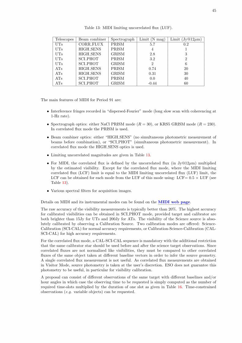
45
Table 13: MIDI limiting uncorrelated flux (LUF).
Telescopes Beam combiner Spectrograph Limit (N mag) Limit (Jy@12µm)UTs CORR FLUX PRISM 5.7 0.2UTs HIGH SENS PRISM 4 1UTs HIGH SENS GRISM 2.8 3UTs SCI PHOT PRISM 3.2 2UTs SCI PHOT GRISM 2 6ATs HIGH SENS PRISM 0.74 20ATs HIGH SENS GRISM 0.31 30ATs SCI PHOT PRISM 0.0 40ATs SCI PHOT GRISM -0.44 60
The main features of MIDI for Period 91 are:
• Interference fringes recorded in “dispersed-Fourier” mode (long slow scan with coherencing at1-Hz rate).
• Spectrograph optics: either NaCl PRISM mode (R = 30), or KRS5 GRISM mode (R = 230).In correlated flux mode the PRISM is used.
• Beam combiner optics: either “HIGH SENS” (no simultaneous photometric measurement ofbeams before combination), or “SCI PHOT” (simultaneous photometric measurement). Incorrelated flux mode the HIGH SENS optics is used.
• Limiting uncorrelated magnitudes are given in Table 13.
• For MIDI, the correlated flux is defined by the uncorrelated flux (in Jy@12µm) multipliedby the estimated visibility. Except for the correlated flux mode, where the MIDI limitingcorrelated flux (LCF) limit is equal to the MIDI limiting uncorrelated flux (LUF) limit, theLCF can be obtained for each mode from the LUF of this mode using: LCF= 0.5 × LUF (seeTable 13).
• Various spectral filters for acquisition images.
Details on MIDI and its instrumental modes can be found on the MIDI web page.
The raw accuracy of the visibility measurements is typically better than 20%. The highest accuracyfor calibrated visibilities can be obtained in SCI PHOT mode, provided target and calibrator areboth brighter than 15Jy for UTs and 200Jy for ATs. The visibility of the Science source is abso-lutely calibrated by observing a Calibration Source. Two calibration modes are offered: Science-Calibration (SCI-CAL) for normal accuracy requirements, or Calibration-Science-Calibration (CAL-SCI-CAL) for high accuracy requirements.
For the correlated flux mode, a CAL-SCI-CAL sequence is mandatory with the additional restrictionthat the same calibrator star should be used before and after the science target observations. Sincecorrelated fluxes are not normalized like visibilities, they must be compared to other correlatedfluxes of the same object taken at different baseline vectors in order to infer the source geometry.A single correlated flux measurement is not useful. As correlated flux measurements are obtainedin Visitor Mode, source photometry is taken at the user’s discretion. ESO does not guarantee thisphotometry to be useful, in particular for visibility calibration.
A proposal can consist of different observations of the same target with different baselines and/orhour angles in which case the observing time to be requested is simply computed as the number ofrequired time-slots multiplied by the duration of one slot as given in Table 16. Time-constrainedobservations (e.g. variable objects) can be requested.
46
6.12 AMBER, Astronomical Multi-BEam combineR
AMBER is a near-infrared, multi-beam interferometric instrument, combining up to 3 telescopessimultaneously. In Period 91, AMBER can be used with UTs or ATs. For specifications of the UTand AT performances see Section 4.2.2 and Section 4.2.4. All possible triplets of UTs are available,and a number of selected AT combinations. For the telescope positions and baseline lengths of thedifferent AT and UT baselines, please refer to the VLTI baseline page.
Because of the limited availability of UTs for AMBER, any scientific programme on the UTs shouldbe designed so that scientifically meaningful results can be achieved in a single night.
Important note: In addition, in order to allow for the installation of the Deformable SecondaryMirror, UT4 will not be available during part of Period 92. Large Programmes using UT4 withAMBER should take this limited availability of UT4 into account.
6.12.1 Spectral Modes and Coverage
The following spectral modes are offered: the Low Resolution H+K bands (LR-HK), MediumResolution K band (MR-K), High Resolution K band (HR-K) and Medium Resolution H Band(MR-H). For central wavelengths and wavelength coverages for LR-HK, MR-K, MR-H and HR-Ksee the AMBER web page.
6.12.2 Integration times, DIT
External fringe tracking with FINITO is available on both the UTs and the ATs. The use ofFINITO allows the entire AMBER detector to be read, maximizing simultaneous spectral coverage.It also allows the AMBER DITs to be adjusted to yield sufficient signal-to-noise ratio per frame inthe fringes. However, the DIT has to remain small since, even with the help of the fringe tracker,interferometric fringes get significantly blurred after integrations lasting seconds. Note that mediumand high resolution are only offered with external fringe-tracking as standard setup.
If no fringe tracker is used (i.e. faint and/or extended objects, or airmass too high) the integra-tion times with AMBER will have to be short to minimise the blurring caused by the atmosphericturbulence. In Low Resolution, without external fringe tracking, the maximum authorized DITs areset to 100ms on the ATs and 50ms on the UTs. If absolute visibility measurements is the goal, theshortest authorized DITs are recommended (see Table 2 in the Template manual); if closure-phaseand wavelength differential-mode are the quantities of interest, the maximum recommended DITshould be used.
As of Period 91 it will be possible (only in visitor mode) to operate AMBER in self-coherencingmode which significantly improves the quality of data when FINITO cannot be used for fringetracking. Check the AMBER Users’ Manual for details.
Special Modes: Special Programmes may require a different combination of modes and DITs.This is the case when using MR or HR without external fringe-tracking. A shorter DIT stronglyreduces the limiting magnitude. It also reduces the spectral coverage that can be read. Any proposalrequiring a non-standard DIT should carefully detail the justification and the technical feasibility.It will be scheduled in Visitor Mode.
In Service Mode the AMBER DITs ought to be chosen while preparing the Phase II. The AMBERtemplate manual, available on the AMBER documentation page, provides the recommendedDITs for all offered configurations.
6.12.3 Limiting magnitudes
AMBER and the VLTI have limitations in magnitude (V-band, H-band and K-band), fringe contrast(H-band and K-band), airmass and seeing. The details of these limitations can be found on the
47
AMBER web page:, as well as the most updated values on visibility accuracy and closure phaseaccuracy.
The limiting magnitudes are estimates on the basis of at least 50% of the frames being successfullyprocessed by the AMBER pipeline. If a lower yield rate is accepted, an increase of up to 0.5 in thelimiting magnitude can be achieved. In this case, the user should account for additional integrationin the same spectral band (Section 6.12.5) to obtain more frames.
The limiting correlated magnitude depends on the AMBER spectral resolution, the FINITO trackingmode (No-Tracking, Group-Tracking or Fringe-Tracking), and the seeing conditions. The maininterest of FINITO Group-Tracking at faint magnitudes is to enhance the SNR on the AMBERclosure-phase, but reducing the flux in the H-band.
In order to be observable with FINITO, the target should have:
H magnitude: -2 to 5 (ATs) 1 to 7 (UTs)Visibility in H: > 15% (ATs) >10% (UTs)
6.12.4 Calibration strategies
AMBER requires frequent calibration on-sky, using calibrator stars. We offer two calibration modes:“CAL-SCI-CAL” and “CAL-SCI”. The first one is the standard mode which should be used in mostcases, in particular when absolute calibration is required for best accuracy. Absolute calibration isrequired in most programmes, but for some programmes wavelength differential quantities providethe astrophysical information. In that case, “CAL-SCI” (or indifferently “SCI-CAL”) is sufficient.
The choice of on-sky calibration strategy should be specified in the “calibration request” section ofthe proposal. The strategy will be reviewed particularly carefully during the technicalfeasibility. Proper justification must be provided if “CAL-SCI” is requested instead ofthe standard “CAL-SCI-CAL”.
6.12.5 Execution times
For each Observing Block (OB), either SCI or CAL the proposer(s) should consider the following:
• Acquisition requires 10min in HR or MR, 5 minutes in LR, including the spectrograph setupand the recording of the calibration fringes (so called P2VM). See Table 16 for more details.
• Integration requires 15min. A maximum of 3 integrations is allowed per OB, which couldconsist in repeating 3 times the same integration or 3 integrations around 3 different centralwavelengths within the same spectral setup.
Hence a normal “CAL-SCI-CAL” sequence requires 75min in MR or HR and 60min in LR.
When observing targets close to the limiting magnitude in MR or HR, it is recommended to doubleor triple the integration, and to focus on wavelength differential quantities. Hence a “SCI-CAL”sequence with triple integration requires 2×1h=2h.
Using a non-standard DIT (below 200ms in MR and HR, or below 25ms in LR, see Section 6.12.2)can strongly reduce the spectral coverage available within one integration. To obtain measurementsat different position within the range of the spectrograph setup, the user can use 2 or 3 integrationswith different central wavelengths.
6.13 VIRCAM, VISTA InfraRed CAMera
VISTA (Section 4.2.5) is equipped with the near infrared camera VISTA InfraRed CAMera(VIRCAM), which covers a 1.65 degree diameter field of view with a loosely packed detector mo-saic totalling ≈ 67 million pixels of mean size 0.339′′. The point spread function (PSF) of thetelescope+camera system including pixels is measured to have a FHWM of 0.51′′.
Further information on this instrument can be found on the VISTA web page.
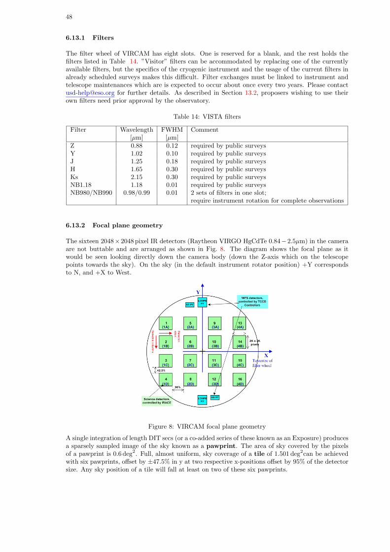
48
6.13.1 Filters
The filter wheel of VIRCAM has eight slots. One is reserved for a blank, and the rest holds thefilters listed in Table 14. ”Visitor” filters can be accommodated by replacing one of the currentlyavailable filters, but the specifics of the cryogenic instrument and the usage of the current filters inalready scheduled surveys makes this difficult. Filter exchanges must be linked to instrument andtelescope maintenances which are is expected to occur about once every two years. Please [email protected] for further details. As described in Section 13.2, proposers wishing to use theirown filters need prior approval by the observatory.
Table 14: VISTA filters
Filter Wavelength FWHM Comment[µm] [µm]
Z 0.88 0.12 required by public surveysY 1.02 0.10 required by public surveysJ 1.25 0.18 required by public surveysH 1.65 0.30 required by public surveysKs 2.15 0.30 required by public surveysNB1.18 1.18 0.01 required by public surveysNB980/NB990 0.98/0.99 0.01 2 sets of filters in one slot;
require instrument rotation for complete observations
6.13.2 Focal plane geometry
The sixteen 2048×2048 pixel IR detectors (Raytheon VIRGO HgCdTe 0.84−2.5µm) in the cameraare not buttable and are arranged as shown in Fig. 8. The diagram shows the focal plane as itwould be seen looking directly down the camera body (down the Z-axis which on the telescopepoints towards the sky). On the sky (in the default instrument rotator position) +Y correspondsto N, and +X to West.
Figure 8: VIRCAM focal plane geometry
A single integration of length DIT secs (or a co-added series of these known as an Exposure) producesa sparsely sampled image of the sky known as a pawprint. The area of sky covered by the pixelsof a pawprint is 0.6 deg2. Full, almost uniform, sky coverage of a tile of 1.501 deg2can be achievedwith six pawprints, offset by ±47.5% in y at two respective x-positions offset by 95% of the detectorsize. Any sky position of a tile will fall at least on two of these six pawprints.
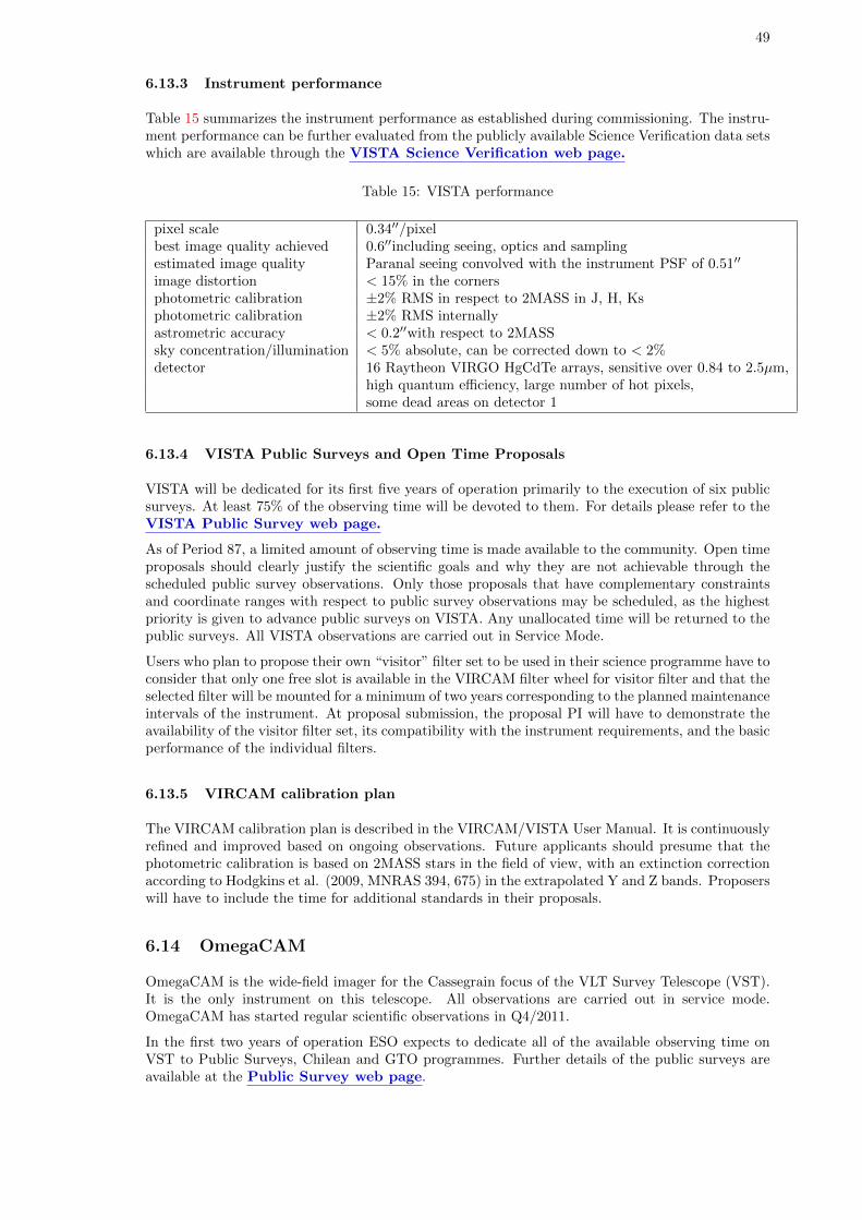
49
6.13.3 Instrument performance
Table 15 summarizes the instrument performance as established during commissioning. The instru-ment performance can be further evaluated from the publicly available Science Verification data setswhich are available through the VISTA Science Verification web page.
Table 15: VISTA performance
pixel scale 0.34′′/pixelbest image quality achieved 0.6′′including seeing, optics and samplingestimated image quality Paranal seeing convolved with the instrument PSF of 0.51′′
image distortion < 15% in the cornersphotometric calibration ±2% RMS in respect to 2MASS in J, H, Ksphotometric calibration ±2% RMS internallyastrometric accuracy < 0.2′′with respect to 2MASSsky concentration/illumination < 5% absolute, can be corrected down to < 2%detector 16 Raytheon VIRGO HgCdTe arrays, sensitive over 0.84 to 2.5µm,
high quantum efficiency, large number of hot pixels,some dead areas on detector 1
6.13.4 VISTA Public Surveys and Open Time Proposals
VISTA will be dedicated for its first five years of operation primarily to the execution of six publicsurveys. At least 75% of the observing time will be devoted to them. For details please refer to theVISTA Public Survey web page.
As of Period 87, a limited amount of observing time is made available to the community. Open timeproposals should clearly justify the scientific goals and why they are not achievable through thescheduled public survey observations. Only those proposals that have complementary constraintsand coordinate ranges with respect to public survey observations may be scheduled, as the highestpriority is given to advance public surveys on VISTA. Any unallocated time will be returned to thepublic surveys. All VISTA observations are carried out in Service Mode.
Users who plan to propose their own “visitor” filter set to be used in their science programme have toconsider that only one free slot is available in the VIRCAM filter wheel for visitor filter and that theselected filter will be mounted for a minimum of two years corresponding to the planned maintenanceintervals of the instrument. At proposal submission, the proposal PI will have to demonstrate theavailability of the visitor filter set, its compatibility with the instrument requirements, and the basicperformance of the individual filters.
6.13.5 VIRCAM calibration plan
The VIRCAM calibration plan is described in the VIRCAM/VISTA User Manual. It is continuouslyrefined and improved based on ongoing observations. Future applicants should presume that thephotometric calibration is based on 2MASS stars in the field of view, with an extinction correctionaccording to Hodgkins et al. (2009, MNRAS 394, 675) in the extrapolated Y and Z bands. Proposerswill have to include the time for additional standards in their proposals.
6.14 OmegaCAM
OmegaCAM is the wide-field imager for the Cassegrain focus of the VLT Survey Telescope (VST).It is the only instrument on this telescope. All observations are carried out in service mode.OmegaCAM has started regular scientific observations in Q4/2011.
In the first two years of operation ESO expects to dedicate all of the available observing time onVST to Public Surveys, Chilean and GTO programmes. Further details of the public surveys areavailable at the Public Survey web page.
50
Important note: Only Chilean and GTO programme proposals will be accepted in Period 91(Sects. 11.4 & 13.1). ESO reserves the right to reject any submitted proposals that do not conformto these requirements.
In the first semesters of operation there has been a lack of OmegaCAM programs that accept relaxedobserving conditions. ESO therefore especially encourages proposals (GTO/Chilean for THN cloudsor seeing ∼>1.5. Also the full moon period has typically been undersubscribed for moderate to largeseeing. Possible science cases include proper motion studies, photometric monitoring in single fields,and generally accumulating photons in pre-calibrated fields.
The VST/OmegaCAM system is designed to critically sample the best seeing at Paranal over a widefield: the VST provides a 1 degree unvignetted field of view, which OmegaCAM samples with a32-CCD, 16k x 16k detector mosaic at 0.21 arcsec per pixel. The CCDs are thinned, blue-sensitive,3-edge buttable CCD44-82 e2v devices of high cosmetic quality. Image quality is specified such thatin the absence of seeing 80% of the energy from a point source should fall within a 2x2 pixel areaover the full field. The field distortion is very low, so that the image scale is virtually constant overthe whole field. There are narrow gaps between the CCDs: the overall geometric filling factor ofthe array is 91%.
In addition to the 32 CCDs making up the science array, OmegaCAM also contains four auxiliaryCCDs around the edges of the field. Two of these are used for autoguiding, so that both fieldposition and rotation can be tracked accurately. The other two auxiliary CCDs are mounted 2mmoutside the focal plane (one in front, one behind), and are used for recording defocused star imagesfor curvature wavefront sensing and controlling the active optics system of the VST.
OmegaCAM contains a 12-filter exchange mechanism. Currently the available filters include theSloan ugriz set, Johnson B and V filters, several narrow-band filter mosaics, a Stromgren v filter,and a special calibration filter. OmegaCAM data are taken in the context of a calibration plan thatensures that all data can be photometrically and astrometrically calibrated to 0.05 magnitude and0.1 arcsec rms precision, respectively.
The image quality distribution measured on OmegaCAM images in g, r, i between August 2011 andJanuary 2012 is available in the OmegaCAM Web page. These measurements show median IQof 0.80-0.85′′ in r and i bands, and 0.95′′ in g band. The numbers are consistent with an outsidemedian seeing of 0.8′′ at 500-600nm, convolved with an internal IQ of ∼0.4′′ . Users are encouragedto take these on-detector statistics into account when defining seeing constraints for Phase 1 and 2.In operations these constraints are always interpreted as IQ on detector, not the outside seeing.
Please see the OmegaCAM page for more details, including Phase I and II manuals.
7 Scientific Instruments: Chajnantor
7.1 SHFI
The APEX Swedish Heterodyne Facility Instrument SHFI contains 4 single pixel receivers:
• APEX-1: a Single Side Band (SSB) Superconductor-Insulator-Superconductor (SIS) receivercovering 211–275 GHz with SSB receiver temperature Trec around 130 K between 210 and260 GHz and 180 K between 260 and 270 GHz. APEX-1 covers low frequencies, allowing ob-servations during conditions with PWV>2 mm. Larger proposals for PWV>2 mm conditionsare encouraged.
• APEX-2: a Single Side Band receiver covering 275–370 GHz with SSB receiver temperatureTrec around 135 K. Observations at these frequencies generally require PWV<2 mm conditions.
• APEX-3: a Double Side Band (DSB) SIS receiver covering 385–500 GHz with DSB Trec
around 110 K. Observations in this frequency range require the best quartile of precipitablewater vapour conditions (PWV <0.5 mm). Only a limited amount of observing time will beavailable on APEX-3, so proposals should be self-contained and the requested amount of timeshould be modest.
51
• APEX-T2: a Double Side Band (DSB) Hot Electron Bolometer (HEB) receiver operating at1.25-1.39 THz with DSB Trec around 1200 K. APEX-T2 is offered conditional to a succesfulrepair mission planned in January 2013. THz observations require excellent weather conditions(PWV<0.2 mm). APEX-T2 proposals should therefore be very short and concentrate onbright sources.
Further information on the SHFI receivers can be found on the APEX instrumentation pages.Since June 2011, SHFI uses two XFFTS units as back-end. These units cover the full 4 GHzintermediate frequency bandwidth with a fixed overlap region of 1 GHz in the centre. Each XFFTSunit provides 32768 spectral channels with a fixed separation of 76kHz (0.1km/s).
For exposure time calculations, users should use the SHFI observing time calculator. Note thatthe time needed to search for an appropriate off-source position in extended line-emitting regions isnot included. SHFI users wishing to map extended line-emitting regions should either provide anappropriate off-source position, or request additional observing time in the technical justificationsection to search for such a position. The overhead for this amounts to ∼30 min per field.
7.2 LABOCA, the Large APEX Bolometer Camera
LABOCA is a 295 channel bolometer array, operating in the 870µm atmospheric window, with abeam size of 19.′′2±0.′′7 and a total field of view of 11.4′.
An overview of the instrument is given on the APEX home page:www.apex-telescope.org/bolometer/laboca/.
The following observing patterns will be offered:
• Spiral mode;
• Raster map in spiral mode;
• On-The-Fly mapping (OTF).
• Point source photometry mode.
The point source photometry mode consists of single pixel chopping, using a sensitive and stablepixel near the optical axis (currently pixel 71). As the LABOCA pixels are separated by twice thebeam size, single pixel chopping improves the on-source efficiency from 6.25% in a Nyquist sampledmap to ∼30% in photometry mode. The same RMS can thus be reached 4.8 times faster thanin mapping mode. The recommended wobbler throw and frequency are 50′′ and 1 Hz. The recom-mended nodding time is 30s, but can be adapted to the weather conditions. The data can be reducedusing the Data Reduction Software for Bolometer Arrays. Note that due to remaining insta-bilities in the atmosphere and the instrument itself, the photometric accuracy obtained from thesewobbler on-off observations is not as accurate as in mapping observations. The required atmosphericstability usually requires PWV<1mm conditions. There are two important requirements to use thephotometry mode: (1) the positions should be known with an accuracy of ∼<1′′, and (2) the sourcesshould not have other emission within the wobbler throw radius.
For mapping, the main advantages of the spiral modes are that (1) the scanned area is only slightlylarger than the LABOCA field of view, leading to a maximum of integrations on the central 11′ fieldof view, and (2) the overheads by the telescope control system are much smaller, as the spirals usea continuous data taking mode while there is a “dead” time when the telescope turns at the edgesof the OTF maps. The optimal observing pattern depends on the spatial extent of the source to beimaged. Recommendations are provided on the APEX home page:www.apex-telescope.org/bolometer/laboca/observing/.
For integration time calculations, users should assume the following values: Noise Equivalent FluxDensity (NEFD)=120 mJy s1/2 and 230 working bolometers. For point source detection experiments,one can apply a low frequency sky noise filtering, improving the sensitivity to NEFD∼75 mJy s1/2.All proposers should use the LABOCA observing time calculator, available fromwww.apex-telescope.org/bolometer/laboca/obscalc/.
52
This tool allows one to calculate the total integration time required to reach a given RMS or theRMS for a given total integration time. Users should always include the generic 65% overheadfactor provided by the calculator. This 65% overhead includes acquisition, software setup, readout,telescope slewing and calibrations (skydip, pointing, focus and flux calibration).
7.3 SABOCA, the Submillimetre APEX Bolometer Camera
SABOCA is a bolometer array operating in the atmospheric window at 350µm (855 GHz). SABOCAconsists of an array of 39 superconducting TES (Transition Edge Sensor) thermistors with SQUID(Superconducting Quantum Interference Device) amplification and multiplexing. Of these, 37 arearranged in a hexagonal layout consisting of a centre channel and 3 concentric hexagons. Two addi-tional bolometers, identical to the inner 37 but optically not coupled (called blind bolometers) wereadded to the layout at two diametral opposite positions, for monitoring purposes. The bolometersare designed to be operated at a temperature of about 300 mK, provided by a cryostat using liquidnitrogen and helium, in combination with a close-cycle helium-3 sorption cooler.
The APEX beam size at this wavelength is 7.7′′, and the total field of view for SABOCA is 90′′.The array is undersampled on the sky; the separation between channels is twice the beam size (15′′).To obtain fully sampled maps it is necessary to move the array on the sky during observations byscanning in one direction and then stepping in the other, or by moving in a circular or spiral patternin the telescope or astronomical coordinate system.
The photometry mode can also be used for SABOCA. The implementation is similar to LABOCA,though a smaller wobbler throw of 25′′ is recommended. The required observing time to reach thesame RMS for a point source is a factor of 6.2 shorter compared to the mapping mode. Potentialusers of the SABOCA photometry mode should be aware that a very accurate pointing is essentialto use this mode. This generally requires the availability of a bright (S350µm > 1 Jy) pointing sourcewithin 10◦ of the targets. In addition, very stable conditions with PWV<0.5 mm are required.
During period 91, SABOCA is expected to be available only in July 2013. Exposure time esti-mates should assume a noise equivalent flux density, NEFD = 200 Jy s1/2, weather conditions ofPWV=0.5mm, 37 working bolometers and a 90% overhead for slewing, pointing, focus and calibra-tions. A dedicated SABOCA integration time calculator is available athttp://www.apex-telescope.org/bolometer/saboca/obscalc/.
Note that a first commissioning of the Artemis instrument will occur in March 2013. If the 350µmarray of Artemis is more performant, accepted SABOCA programmes may be executed with Artemisinstead.
7.4 FLASH heterodyne receiver (MPIfR PI instrument)
The 345 GHz channel of the MPIfR PI instrument FLASH is again offered to the ESO communityon a collaborative basis with MPIfR. Users who would like to use FLASH shall contact thePI, Dr. Rolf Guesten (rguesten[AT]mpifr-bonn.mpg.de) at least two weeks prior tosubmitting the proposal for which they are requesting approval. Members of the PI teamshould be included as CoIs on the proposal. The observations will be done by the PI team duringa maximum of 3 days. Large programmes or time critical observations with FLASH will not beaccepted.
FLASH consists of two single pixel sideband-separating receiver covering the 280–370 GHz and 385-495 GHz range with typical Trx(SSB)=100–150 K. The receivers are a copy of the ALMA band 7 and8. The PI XFFTS backends has the same characteristics as the facility XFFTS. Both IF sidebandsare recorded simultaneously, allowing to cover 2×4 GHz, separated by 12 GHz in each band, i.e. 16GHz in total. Only a limited amount of observing time is available to the ESO community, andpreference will be given to proposals using the dual-beam, wide-bandwidth capabilities of FLASH.
Technical questions on FLASH should be directed to the ESO APEX Project Scientist, Dr. CarlosDe Breuck (cdebreuc[AT]eso.org).
53
7.5 CHAMP+: The Carbon Heterodyne Array of the MPIfR
CHAMP+ is a MPIfR PI instrument which is offered to the ESO community on a collaborativebasis with MPIfR. CHAMP+ is a heterodyne array operating simultaneously in the 350µm and450µm atmospheric windows. It is composed of 14 pixels, divided into two sub-arrays of 7-pixelseach, arranged in a hexagonal configuration. The two sub-arrays operate at orthogonal signalpolarizations. The RF tuning range is 620-720 GHz for the 450µm and 780-900 GHz for the 350µmsub-array.
The beam-spacing is 2.15 times the half-power beam widths of 8.8′′(at 692 GHz) and 7.7′′(806 GHz),so only the central pixels of the two sub-arrays are spatially co-aligned on sky. The front-end isconnected to a FFT spectrometer array back-end, providing up to 2.8 GHz of bandwidth for eachdetector pixel, with spectral resolution of 212 kHz. The system is operated in single-sideband mode.For exposure time calculations, users should assume SSB system temperatures of typically 1000–1400 K (at the frequency of the CO(6-5) line at 691 GHz) and 2500–4000 K (CO(7-6) at 806 GHz,closer to the edge of the atmospheric window). The image gain suppression is better than 10-15 dBfor all pixels (in the centre of the IF band). All CHAMP+ proposals should add a 20% additionaloverhead for instrument characterisation and calibration purposes such as the establishment of apointing model and the determination of the gain curves.
Further information on CHAMP+ can be found on the CHAMP+ homepage.
As the operation of CHAMP+ requires the presence of the instrument team, all ESO CHAMP+observations will be scheduled on fixed dates. The exact dates of operation for Period 91 have notbeen determined yet, but they are likely to be in June 2013, when the atmospheric transparency isexpected to be better. Large programmes or time critical observations with CHAMP+ will not beaccepted.
Users who would like to use CHAMP+ should contact the PI, Dr. Rolf Guesten(rguesten[AT]mpifr-bonn.mpg.de), at least two weeks prior to submitting the proposalfor which they are requesting approval. Members of the PI team that will operate the instru-ment for the guest proposal shall be included as CoIs on the proposal.
7.6 Z-Spec: The broadband millimeter-wave spectrometer
Z-Spec is a single-beam diffraction-grating spectrograph which disperses the 190–308 GHz bandacross a linear array of 160 bolometers. The detector spacing increases from ∼ 1 part in 400 atthe low-frequency end (∆ν = 500 MHz), to ∼ 1 part in 250 at the high-frequency end of the band(∆ν = 1200 MHz), while the spectrometer resolving power runs from R∼300 at low frequenciesto R∼250 at the high frequency end of the band. Z-Spec observes in a traditional chop-and-nodmode, with the secondary chopping between 1 and 2 Hz, and a nod period of 20 seconds. Thechannel-to-channel calibration uncertainties are estimated to be less than 10% except at the lowestfrequencies, which are degraded by the wing of the 186 GHz atmospheric water line.
The measured sensitivity of Z-Spec at APEX varies from ∼800 mJy s1/2, or 7.3×10⁻¹⁸ W m−2 sec1/2
per channel at the central frequencies to >1 Jy s1/2 below 210 GHz. In 2 hours, the 3σ sensitivity perchannel is thus 28 mJy. Since Z-Spec does not resolve most emission lines, on average 1.6 channelsare required to measure a line flux. This translates to a minimum detectable line flux (3σ) in 2hours of 4.4×10⁻¹⁹ W m−2 in the typical 1 GHz Z-Spec channel. Users should add a 20% overheadfactor for bandpass calibrations.
Z-Spec is offered as a PI instrument to the ESO community in Period 91 . The operations willbe grouped in order to save Helium consumption. The observations are expected to occur in Aprilor May 2013. Time critical observations are therefore very difficult to schedule. There are noguarantees that Z-Spec will be offered beyond Period 91, and no large programmes will be accepted.
Users who would like to use Z-Spec should contact the instrument team at least twoweeks prior to submitting the proposal for which they are requesting approval. Thefollowing members of the instrument team that will operate Z-Spec for the guest proposal shallbe included as CoIs on the proposal: Dr. James Aguirre (University of Pennsylvania), Dr. MattBradford (Jet Propulsion Laboratory) and Dr. Jason Glenn (University of Colorado). Additional
54
CoIs may be requested by the instrument team. For technical questions, users should contact theESO APEX Project Scientist, Dr. Carlos De Breuck.
8 Visitor Instruments
Visitor instruments can be mounted at the VLTI, the NTT, the 3.6-m telescope and at APEX inorder to permit innovative observations by teams with their stand-alone instruments or to test newinstrumental concepts for the development of new facility instruments.
No Visitor Instrument focus is available on the VLT due to the installation of KMOS. Given thearrival of the second generation VLTI instruments, ESO cannot guarantee the availability of a VLTIVisitor focus beyond Period 91.
The requirements for visitor instruments are substantially reduced compared to the requirementsfor fully integrated facility instruments. A set of guidelines on how to propose a visitor instrumenton the VLTI is available athttp://www.eso.org/sci/facilities/paranal/instruments/vlti-visitor/.
Technical information on the interface for VLTI Visitor Instruments can be found athttp://www.eso.org/sci/facilities/paranal/instruments/vlti-visitor/requirements.html.
Technical information on the interface to the NTT and 3.6-m telescope is found athttp://www.eso.org/sci/facilities/lasilla/instruments/visitor/VisitorInstruments.pdf.
9 How to estimate overheads
Service and Visitor Mode observers must include the overhead times associated with their sciencetarget observations in their proposals. For Service Mode observations, the total execution timerequested for every planned Observation Block (OB) must include all overheads, from telescopepresetting and target acquisition to all other relevant instrument overheads. Proposers should notethat all overheads must be accounted for within one hour for each OB (Section 12.2.1). Time fornight-time calibrations and associated overheads must be included only in cases where the accuracyof the observatory calibration plan is not deemed sufficient for the science goals. Please note thatcalibrations need to be executed as part of the science OBs in some instrument modes (e.g. attachedcalibrations for all VIMOS IFU and MOS modes; see the VIMOS User Manual for details). Thetime needed to execute such attached calibrations must be included in the proposal (Section 10.2).Table 16 provides typical overheads associated with individual instruments. More details can befound in the instrument manuals.
Proposers are strongly encouraged to make use of the Phase 2 Preparation Tool (P2PP) dur-ing the preparation of their proposals in order to accurately determine the overheads required bytheir programmes. It is possible to simulate the detailed breakdown of the programme in terms ofits constituent Observation Blocks (OBs) using the P2PP tutorial accounts: see Section 1.4 of theP2PP User Manuals available at:http://www.eso.org/sci/observing/phase2/P2PPTool/P2PPDocumentation.htmlfor La Silla observations;for observations with Paranal instruments seehttp://www.eso.org/sci/observing/phase2/P2PPSurveys/P2PP3Documentation.html.
The Execution Time Report option offered by P2PP provides an accurate estimate of the timeneeded for the execution of each OB including all the necessary overheads. The total execution timeestimated by P2PP reflects the official ESO time accounting in Service Mode.
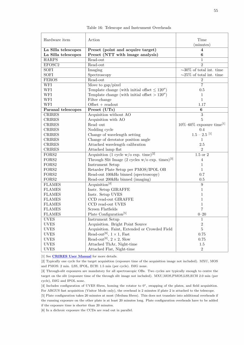
55
Table 16: Telescope and Instrument Overheads
Hardware item Action Time(minutes)
La Silla telescopes Preset (point and acquire target) 4La Silla telescopes Preset (NTT with image analysis) 6HARPS Read-out 1EFOSC2 Read-out 2SOFI Imaging ∼30% of total int. timeSOFI Spectroscopy ∼25% of total int. timeFEROS Read-out 2WFI Move to gap/pixel 7WFI Template change (with initial offset ≤ 120′′) 0.5WFI Template change (with initial offset > 120′′) 1WFI Filter change 1WFI Offset + readout 1.17Paranal telescopes Preset (UTs) 6CRIRES Acquisition without AO 3CRIRES Acquisition with AO 5CRIRES Read–out 10%–60% exposure time[1]
CRIRES Nodding cycle 0.4CRIRES Change of wavelength setting 1.5 – 2.5 [1]
CRIRES Change of derotator position angle 1CRIRES Attached wavelength calibration 2.5CRIRES Attached lamp flat 2
FORS2 Acquisition (1 cycle w/o exp. time)[2] 1.5 or 2FORS2 Through Slit Image (2 cycles w/o exp. times)[3] 4FORS2 Instrument Setup 1FORS2 Retarder Plate Setup per PMOS/IPOL OB 1FORS2 Read-out 100kHz binned (spectroscopy) 0.7FORS2 Read-out 200kHz binned (imaging) 0.5
FLAMES Acquisition[4] 9FLAMES Instr. Setup GIRAFFE 1FLAMES Instr. Setup UVES 1FLAMES CCD read-out GIRAFFE 1FLAMES CCD read-out UVES 1FLAMES Screen Flatfields 7FLAMES Plate Configuration[5] 0–20UVES Instrument Setup 1UVES Acquisition. Bright Point Source 2UVES Acquisition. Faint, Extended or Crowded Field 5UVES Read-out[6], 1× 1, Fast 0.75UVES Read-out[6], 2× 2, Slow 0.75UVES Attached ThAr, Night-time 1.5UVES Attached Flat, Night-time 2
[1] See CRIRES User Manual for more details.
[2] Typically one cycle for the target acquisition (exposure time of the acquisition image not included). MXU, MOS
and PMOS: 2 min. LSS, IPOL, ECH: 1.5 min (per cycle). IMG none.
[3] Through-slit exposures are mandatory for all spectroscopic OBs. Two cycles are typically enough to centre the
target on the slit (exposure time of the through slit image not included). MXU,MOS,PMOS,LSS,ECH 2.0 min (per
cycle), IMG and IPOL none.
[4] Includes configuration of UVES fibres, homing the rotator to 0◦, swapping of the plates, and field acquisition.
For ARGUS fast acquisition (Visitor Mode only), the overhead is 2 minutes if plate 2 is attached to the telescope.
[5] Plate configuration takes 20 minutes at most (Medusa fibres). This does not translate into additional overheads if
the running exposure on the other plate is at least 20 minutes long. Plate configuration overheads have to be added
if the exposure time is shorter than 20 minutes.
[6] In a dichroic exposure the CCDs are read out in parallel.
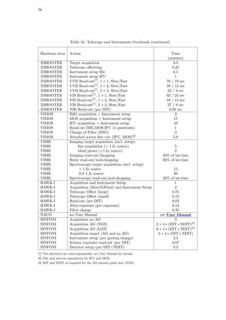
56
Table 16: Telescope and Instruments Overheads (continued)
Hardware item Action Time(minutes)
XSHOOTER Target acquisition 3-5XSHOOTER Telescope offsetting 0.25XSHOOTER Instrument setup Slit 0.5XSHOOTER Instrument setup IFU 1XSHOOTER UVB Read-out[7], 1× 1, Slow/Fast 70 / 19 secXSHOOTER UVB Read-out[7], 1× 2, Slow/Fast 38 / 12 secXSHOOTER UVB Read-out[7], 2× 2, Slow/Fast 22 / 8 secXSHOOTER VIS Read-out[7], 1× 1, Slow/Fast 92 / 24 secXSHOOTER VIS Read-out[7], 1× 2, Slow/Fast 48 / 14 secXSHOOTER VIS Read-out[7], 2× 2, Slow/Fast 27 / 9 secXSHOOTER NIR Read-out (per DIT) 0.88 secVIMOS IMG acquisition + Instrument setup 3VIMOS MOS acquisition + Instrument setup 15VIMOS IFU acquisition + Instrument setup 10VIMOS Read-out IMG,MOS,IFU (4 quadrants) 1VIMOS Change of Filter (IMG) 3VIMOS Attached screen flat+arc (IFU, MOS)[8] 5-8VISIR Imaging target acquisition (incl. setup):VISIR fine acquisition (> 1 Jy source) 5VISIR blind preset (<1 Jy source) 2VISIR Imaging read-out/chopping 50% of int.timeVISIR Burst read-out/nod-chopping 80% of int.timeVISIR Spectroscopy target acquisition (incl. setup):VISIR > 1 Jy source 15VISIR 0.2–1 Jy source 30VISIR Spectroscopy read-out/nod-chopping 50% of int.timeHAWK-I Acquisition and Instrument Setup 1HAWK-I Acquisition (MoveToPixel) and Instrument Setup 3HAWK-I Telescope Offset (large) 0.75HAWK-I Telescope Offset (small) 0.15HAWK-I Read-out (per DIT) 0.03HAWK-I After-exposure (per exposure) 0.13HAWK-I Filter change 0.35NACO see User Manual see User ManualSINFONI Acquisition no AO 3SINFONI Acquisition AO (NGS) 2 + 4 ∗ (DIT ∗NDIT)[9]
SINFONI Acquisition AO (LGS) 9 + 4 ∗ (DIT ∗NDIT)[9]
SINFONI Acquisition target (AO and no AO) 4 + 4 ∗ (DIT ∗NDIT)SINFONI Instrument setup (per grating change) 2.5SINFONI Science exposure read-out (per DIT) 0.07SINFONI Detector setup (per DIT×NDIT) 0.3
[7] The detectors are read sequentially; see User Manual for details.
[8] Flat and arcs are mandatory for IFU and MOS.
[9] DIT and NDIT as required for the AO natural guide star (NGS).
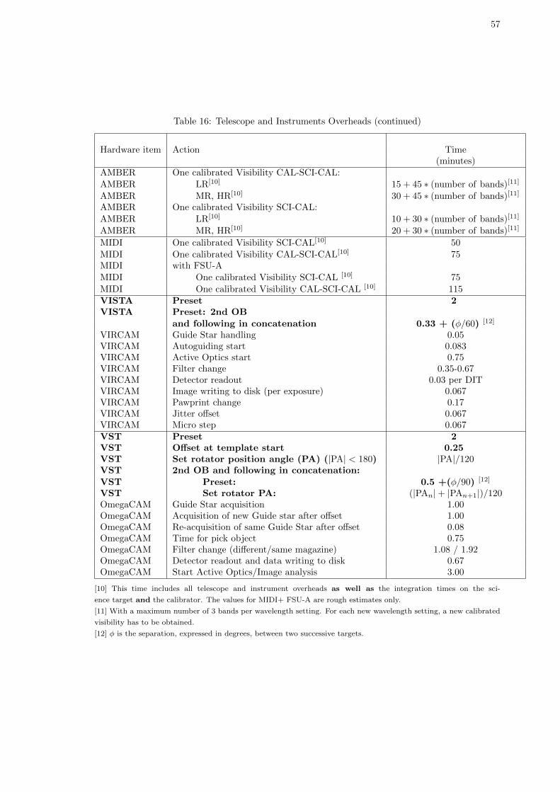
57
Table 16: Telescope and Instruments Overheads (continued)
Hardware item Action Time(minutes)
AMBER One calibrated Visibility CAL-SCI-CAL:AMBER LR[10] 15 + 45 ∗ (number of bands)[11]
AMBER MR, HR[10] 30 + 45 ∗ (number of bands)[11]
AMBER One calibrated Visibility SCI-CAL:AMBER LR[10] 10 + 30 ∗ (number of bands)[11]
AMBER MR, HR[10] 20 + 30 ∗ (number of bands)[11]
MIDI One calibrated Visibility SCI-CAL[10] 50MIDI One calibrated Visibility CAL-SCI-CAL[10] 75MIDI with FSU-AMIDI One calibrated Visibility SCI-CAL [10] 75MIDI One calibrated Visibility CAL-SCI-CAL [10] 115VISTA Preset 2VISTA Preset: 2nd OB
and following in concatenation 0.33 + (φ/60) [12]
VIRCAM Guide Star handling 0.05VIRCAM Autoguiding start 0.083VIRCAM Active Optics start 0.75VIRCAM Filter change 0.35-0.67VIRCAM Detector readout 0.03 per DITVIRCAM Image writing to disk (per exposure) 0.067VIRCAM Pawprint change 0.17VIRCAM Jitter offset 0.067VIRCAM Micro step 0.067VST Preset 2VST Offset at template start 0.25VST Set rotator position angle (PA) (|PA| < 180) |PA|/120VST 2nd OB and following in concatenation:VST Preset: 0.5 +(φ/90) [12]
VST Set rotator PA: (|PAn|+ |PAn+1|)/120OmegaCAM Guide Star acquisition 1.00OmegaCAM Acquisition of new Guide star after offset 1.00OmegaCAM Re-acquisition of same Guide Star after offset 0.08OmegaCAM Time for pick object 0.75OmegaCAM Filter change (different/same magazine) 1.08 / 1.92OmegaCAM Detector readout and data writing to disk 0.67OmegaCAM Start Active Optics/Image analysis 3.00
[10] This time includes all telescope and instrument overheads as well as the integration times on the sci-
ence target and the calibrator. The values for MIDI+ FSU-A are rough estimates only.
[11] With a maximum number of 3 bands per wavelength setting. For each new wavelength setting, a new calibrated
visibility has to be obtained.
[12] φ is the separation, expressed in degrees, between two successive targets.
58
10 Calibration Plans and Pipelines
10.1 Data Quality Control
ESO has implemented calibration plans for all instruments. The primary purposes of these plansare to assure data quality, monitor instrument performance and calibrate science observations. Basedon these plans, calibration data are obtained for certain standard instrument modes on a regularbasis. Paranal calibration data are reviewed on a daily basis by Paranal Science Operations and theGarching Data Processing and Quality Control group. A brief summary of the calibration plan foreach instrument is available online from http://www.eso.org/qc/pipeline-status.html.
10.2 Calibration Plans and Calibration of Science Observations
The calibration plans typically aim to calibrate science data to a target accuracy of 5–10%. Thismay not be sufficient for all science programmes.
Important note: Not all instrument modes and/or configurations are covered by the cur-rent calibration plans. Read the appropriate user manual and online documentation carefully(http://www.eso.org/qc/pipeline-status.html).
Daytime calibrations included in the calibration plans (e.g. bias, flat-fields, and arc-lamp exposures)are performed by the Observatory for both Service and Visitor Mode runs. Whenever possible,these calibration data are obtained in the morning, immediately after the conclusion of night-timeoperations. Service and Visitor Mode users receive these data via the CalSelector (see below).
Service Mode runs: Certain ESO specified night-time calibrations (e.g. photometric standardstars, telluric absorption correction stars) are obtained systematically as described by the calibra-tion plan in the instrument-specific user manuals. For many programmes these calibrations maybe sufficient. Service Mode proposers should only request enough time to complete their scienceobservations. If the published calibration plan is not sufficient, Service Mode proposers must requestmore time (including all operational overheads) for additional user-defined calibrations.
Important note: For some instrument modes, calibrations need to be obtained immediately afterthe science observation by means of attached calibration templates. Such attached calibrations arean integral part of the science OB and are not considered as a part of the calibration plan. Theirexecution time must therefore be included in the time applied for.
Visitor Mode runs: Night-time calibrations are the responsibility of the visiting observer with thefollowing exception: up to approximately 30 minutes per night will be used by the observatory staffto obtain standard ESO calibrations. The ESO-obtained data will be used to monitor instrumentperformance and to assure a baseline calibration accuracy within the ESO Science Archive. ESOdoes not guarantee that these standard calibration data will be sufficient to calibrate the VisitorMode science observations to the accuracy desired by the observer. Visitor Mode proposers shouldplan accordingly.
Raw science data and associated calibrations are made available to the respective PIs and delegatesthrough the ESO Science Archive Facility. The CalSelector archive service packs together allthe files needed to process the science data including ancillary files,e.g. acquisition images, etc.).More information on the CalSelector can be found at:http://www.eso.org/sci/archive/calselectorInfo.html.
La Silla: It is the responsibility of the Visiting Astronomer to obtain all night-time and daytimecalibration frames required. Although ESO staff will execute standard day calibration sequences andmake them available to the visitor, all afternoon calibrations and sky flat-fields must be obtainedby the visitor.
Calibration Programmes: Please note that ESO further accepts Calibration Programmes toachieve improved calibration of its instruments (see Section 11.5 for details).
59
10.3 Data Reduction Pipelines
10.3.1 Data Organization: Gasgano and SAFT
Gasgano, a Java-based data file organizer developed and maintained by ESO, is made availableto the community and can be used to manage and organize the astronomical data observed andproduced by all VLT compliant telescopes in a systematic way. Gasgano can be retrieved fromhttp://www.eso.org/gasgano/.
It is also possible to build Unix shell scripts for data organisation using the Stand-Alone FITS Tools(SAFT) available from http://archive.eso.org/saft. In particular, the dfits and fitsort tools canbe used in combination to select groups of related files (i.e. all frames with the same instrumentconfiguration) for processing.
SAFT, and in particular the hierarch28 tool, can be effectively used to handle ESO HIERARCHkeywords, e.g. convert them for use with other packages like IRAF.
10.3.2 Pipelines in the ESO Environment
In collaboration with the various instrument consortia, ESO has undertaken to implement datareduction pipelines for the most commonly used VLT/VLTI instrument modes. These data reductionpipelines serve three main purposes:
• Data quality control: Pipelines are used to produce the quantitative information necessaryto monitor instrument performance (see Section 10.4).
• Master calibration product creation: Pipelines are used to produce master calibrationproducts (e.g. combined bias frames, super-flats, wavelength dispersion solutions).
• Science product creation: Pipelines can be run on the user’s desktop in order to fine-tune the reduction to specific science needs. For this purpose, the algorithmic part of theVLT/VLTI pipelines (pipeline recipes) are available and can be downloaded with the front-end applications, esoRex, Gasgano and Reflex, from http://www.eso.org/pipelines.
A brief summary of current and anticipated VLT/VLTI pipeline availability and functionality foreach instrument is available online fromhttp://www.eso.org/qc/pipeline-status.html.
Available pipelines are installed on Paranal and La Silla, and normally run automatically at alltimes. These online pipelines use standard (but typically not the most recent) archival mastercalibration data to produce quick-look quality control information for the observatory staff, as wellas quick-look science products for supported instrument configurations. These science products areavailable to Visitor Mode observers for review and use. With the exception of HARPS and FEROS,they are not included in the data package delivered to the Visitor Mode observer at the end of theirobserving run. Users may copy these science products onto removable media (CD-ROM and DVD).Blank media are available from the Observatory for this purpose. However, these science productsmay not be the best possible because they do not use the most recent master calibration data.
The Garching-based offline pipelines for VLT/VLTI instruments are run by the Quality Control andData Processing Group (QCDP) to produce certified (quality-checked) master calibration products.These are used to monitor instrument performance and assure that it is maintained within thepublished ranges (see below). PIs and their data delegates can access their raw science and cali-bration data via the ESO Science Archive Facility after authenticating with their User Portalcredentials. Raw data are available via the User Portal shortly after acquisition.
Raw calibration data can be downloaded from the archive by all users immediately. Raw sciencedata are accessible by everyone after the proprietary protection has expired. During the propri-etary period the data are only accessible to the corresponding PIs and their delegates. See theData Access Page and the Archive User Manual for full details.
60
10.4 Quality Control
The ESO pipelines are used to monitor the performance of the various instruments and their tem-poral trends.
Extensive information about Paranal data handling and processing (e.g. zero points, colour terms,wavelength solutions) is maintained on the ESO Quality Control web pages.
The Quality Control Group also maintains the Health Check Monitor with information and dataabout actual and historical instrument performance and trending.
10.5 The ESO Science Data Products Forum
The ESO Science Data Products Forum is a platform for sharing ideas, methods, software anddata to assist with the production of science data products from ESO telescopes. The forum is aservice for the ESO community. Contributions are by users of the ESO instruments.
Users are encouraged to contribute on any topic related to the reduction, calibration and analysisof science data from ESO instruments. Posts might simply describe problems encountered with thedata reduction, or offer solutions to such problems. Software, calibration data or documents up to100MB in size can be attached to any post.
61
Part III
Proposal Types, Policies, and Procedures
11 Proposal Types
For Period 91 the list of proposal types is:
• Normal Programmes
• Large Programmes
• Target of Opportunity
• Guaranteed Time Observations
• Calibration Programmes
• Director’s Discretionary Time
All proposals except Director’s Discretionary Time (DDT) proposals must be submitted by thecurrent deadline. DDT proposals may be submitted at any time.
Only the Normal and Large Programme template forms should be used for the preparation ofproposals. An observing programme, as described in a single proposal, may consist of several runs,e.g. for observations with different instruments, or to be executed in different observing modes orat different epochs. Proposals for Visitor Mode observations (Section 12.1) must request time innights, proposals for Service Mode observations (Section 12.2) must request time in hours. Notethat any given proposal may request a mix of Visitor/Service Mode observations provided that theyare split into separate runs.
• Please note: All proposers (Service and Visitor Mode) must include time for all overheads(telescope + instrument) in their proposals (see Section 9 and Table 16).
11.1 Normal Programmes
Most of the observing time on ESO telescopes will be allocated to Normal Programmes inPeriod 91. Proposers must use the standard LATEX template (Section 3.1). The scientific case ofthe programme may take up to two pages including attachments (figures or tables). The scientificdescription contains two sections:
A) Scientific Rationale
B) Immediate Objective
Attachments are optional. The respective fraction of the above-mentioned two pages occupied bythe scientific description and by the attachments is left to the discretion of the proposers, butattachments are restricted to the second of these pages.
If the proposal contains runs requesting La Silla telescopes and instruments, the duration of eachsuch run must be at least 3 nights, except for runs using Visitor Instruments or for combinations ofcontiguous EFOSC2 and SOFI runs totalling at least 3 nights (Section 4.1).
Proposers should keep in mind the need for each OPC panel to cover a broad range of scientific areas;proposals may not fall within the main area of specialisation of any of the panel members. Proposersshould make sure that the context of their project and its relevance for general astrophysics, as wellas the recent related results, are emphasised in a way that can be understood by their peers regardlessof their expertise.
62
11.2 Large Programmes
Large Programmes are not accepted on the 2.2-m, VST or VISTA telescopes. Due to existingcommitments and upcoming changes Large Programmes will also not be accepted for CRIRES,HAWK-I, NACO and VIMOS, (see Section 1.3 for more details). Also, given the arrival of thesecond generation VLTI instruments, ESO cannot guarantee the availability of MIDI and of a VLTIvisitor instrument focus beyond Period 91.
Up to a maximum of 30% of the observing time distributed by the OPC on the VLT/VLTI can beallocated to Large Programmes. An ESO Large Programme is defined by the criteria listed below.For ESO telescopes, one night is 8 hours in even periods and 10 hours in odd periods.
• A programme requiring a minimum of 100 hours of ESO telescope time.
• A programme that has the potential to lead to a major advance or breakthrough in the fieldof study, has a strong scientific justification, and a plan for a quick and comprehensive effortof data reduction and analysis by a dedicated team.
• Large Programmes can span from 1 to 4 periods (i.e. up to a maximum of two consecutiveyears) for Paranal instruments, and from 1 to 7 periods (i.e. up to Period 97 for La Silla);
• ToO programmes cannot be submitted as Large Programmes (Section 11.3).
A good organisational structure of the proposing team, availability of resources and relevant expertisemust be demonstrated. A special LATEX template must be used for Large Programmes (Section 3.1).The proposers may use a total of three pages (not including figures) for the four sections of thescientific description:
A) Scientific Rationale
B) Immediate Objective
C) Telescope Justification
D) Observing Mode Justification (Visitor or Service)
An additional 2 pages of attachments are permitted. Proposers of Large Programmes should keep inmind that the entire OPC (hence also non-experts in a specific field) as well as the specialised OPCpanels will be evaluating their proposal, and that they should clearly explain the relevanceof the proposed programme to general astrophysics.
If a Large Programme proposal contains runs requesting La Silla telescopes and instruments, theduration of each such run must be at least 3 nights.
Proposers should be aware that the PIs of successful proposals for Large Programmes are requiredto provide all data products (processed images and spectra, catalogues) to the ESO archive bythe time their scientific results are published in a refereed journal. Guidelines for submission ofthese data products, including a description of the required metadata and formats, can be found athttp://archive.eso.org/cms/eso-data/data-submission/. Proposers are invited to write anemail to [email protected] for further information.
During the period of execution of a Large Programme, and upon its completion, the PI will beinvited by ESO to report to the OPC on the programme’s preliminary results. He/she may alsobe asked to give a more comprehensive presentation of the outcome of the programme at an ESOLarge Programme workshop, similar to those of May 19-21, 2003 and of October 13-15, 2008.
11.3 Target of Opportunity
Normally, up to 5% of the available ESO general observing time may be used for Target ofOpportunity (ToO) proposals. For events with exceptional characteristics ESO will also consideroverriding Visitor Mode observations.
63
ESO recognises two categories of Targets of Opportunity:
1. Unpredictable ToOs are those concerning unpredictable astronomical events that requireimmediate observations. The occurrence of such events cannot be foreseen with sufficientanticipation to allow them to be the subject of proposal submission by the regular deadline.They qualify for allocation of Director Discretionary Time. Corresponding applicationsfor observing time should be submitted as DDT proposals (Section 11.6) and not as ToOproposals.
2. Predictable ToOs are those concerning predictable events in a generic sense only. Theseare typically (but not limited to) known transient phenomena and follow-up or coordinatedobservations of targets of special interest. Proposals aimed at studying such events are, in theESO proposal terminology, ToO proposals.
ToO proposals must be submitted using the Normal Programme ESOFORM template. Proposalsshould be for generic targets and/or times. However, if accepted by the OPC the programme willnot be executed until the PI (or one of his/her delegates) contact ESO to request its activation afterthe predicted event has occurred. The observing strategy must be the one approved by the OPC,and the triggers may not exceed the allocated time and number of triggers granted by the OPC.The observations will be conducted in Service Mode and, in exceptional cases, ongoing programmesmay be interrupted. Read more on ToO policy.
As ToO programmes may require a mixture of ToO runs and normal (see 3.2.1) runs proposers arerequested to specify the type of runs (TOO or normal) in the tenth (final) field of the \ObservingRunmacro of the ESOFORM LATEX template. A more detailed description and examples can be foundin the ESOFORM User Manual.
ToO runs are defined as runs for which the target cannot be known more than one week beforethe observation needs to be executed. Such runs will be scheduled for execution upon receipt ofan activation trigger by ESO; the target (and observing time) information will be inserted by theobservatory support staff into generic Observation Blocks (OBs) submitted by the PI at Phase 2.Targets that are unknown at Phase 1 proposal submission time but can be observed more than oneweek after they have been identified should be observed as part of normal (non-ToO) runs. Therelated OBs should be defined or updated by the PI once the target is known. The OBs should bestored in the ESO database with the complete information needed to allow them to be executed aspart of the regular Service Mode queues.
Note that users submitting a ToO programme will need to indicate the number of targets per runand the requested number of triggers per target using the appropriate macros in the LATEX template.A trigger is defined as the request for execution of one Observation Block with a given instrumentat a given epoch. Similar observations to be executed with the same instrument at different epochscount as different triggers, as do observations with different instruments at the same epoch.
Any observing request by other groups at the time an event occurs (e.g. a DDT proposal), withexactly the same scientific goal and aiming at observing the same object, will be rejected by ESO.ToO programmes are not carried over to the following periods.
ToO proposers should bear in mind that ToO proposals are ranked across OPC categories by thewhole OPC (hence including non-experts in their specific field). They should therefore clearlyexplain the relevance of the proposed programme to general astrophysics.
11.3.1 Rapid Response Mode (RRM)
ESO continues to offer VLT Rapid Response Mode (RRM). During Period 91, FORS2 on UT1,UVES and XSHOOTER on UT2, and SINFONI and HAWK-I on UT4 are available in RRM.
RRM proposers should note that:
• A RRM trigger is a special ToO trigger that can only be activated up to 4 hours afteran event. If a longer time span has passed since the event, observations should be requestedthrough normal ToO triggers.

64
• As with ToO programmes, proposers will need to indicate in the LATEX template the numberof targets per run and the requested number of triggers per target.
• RRM runs have to be specified as separate runs in the ESOFORM template.
Upon receiving an encoded alert indicating the coordinates of the target and the associatedObserving Block (OB) to be executed, any ongoing integration will automatically be terminatedand the RRM OB will be executed. Depending on the instrument and the target position, the tele-scope/instrument will be at the location of the target within about 6 minutes following the arrivalof the alert at Paranal. Depending on the target brightness and instrument mode target acquisitionmay take some more time.
RRM observations in Period 91 are subject to the following restrictions:
• The requested instrument must already be in operation. No change of instrument (and tele-scope focus) is accepted by the automatic RRM system.
• RRM activations will be accepted during Service Mode and Visitor Mode runs. They haveoverriding priority over other observations, unless the latter are strictly time-critical.
Additionally, the following instrument specific restrictions apply:
• UVES can only be used with standard wavelength settings;
• FORS2 can only be used in the broad-band imaging, long slit spectroscopic, imaging polari-metric and spectro-polarimetric modes;
• SINFONI is available in NGS and noAO mode but not in LGS mode;
• HAWK-I: all the filters can be used, but the trigger requesters must follow the users’ manualindications closely as far as brightness restrictions of objects in the field are concerned.
The delivery of the encoded alerts to the Paranal Observatory is entirely the responsibility of thePI. Successful PIs will be asked to provide a set of OBs by the Phase 2 deadline, to be certified forexecution as is done for other Service Mode runs. Details on the activation mechanisms and thepreparation of RRM observations can be found at the Phase 2 RRM Observation page.
11.4 Guaranteed Time Observations
Guaranteed Time Observations (GTO) arise from contractual obligations of ESO vis–a–vis theexternal consortia who build ESO instruments (see the GTO Policy page). Guaranteed TimeObservers must submit proposals for their GTO time using the Normal Programme templates, andby the standard proposal deadline. All GTO proposals will be evaluated and ranked together withNormal Programme proposals to provide feedback to the GTO teams on the scientific standing oftheir GTO programmes. In exceptional cases, badly ranked GTO proposals may not be scheduled.The policies describing the obligations of Guaranteed Time Observers are defined in Appendix 2 ofthe ESO Council document ESO/Cou-996.
In general, GTO runs must be conducted in Visitor Mode (Section 12.1). The only exceptions arethose explicitly stated in the contractual agreement between ESO and the corresponding externalconsortium. However ESO may exceptionally transfer some GTO runs from Visitor Mode to ServiceMode for operational reasons (such as the availability of VLTI baselines or the availability of theLGSF).
Some GTO programmes require ToO runs2 (see Section 11.3). If this is the case then this should bespecified in the ESOFORM package using the \ObservingRun macro of the LATEX template.
2The possibility for GTO teams to request ToO observations as part of their guaranteed time is restricted to thosecases in which this option is explicitly mentioned in the GTO contract.
65
11.5 Proposals for Calibration Programmes
ESO operates a large number of complex instruments with many possible configurations and observ-ing modes. Although the Observatory executes a rigorous calibration plan for each instrument, ESOdoes not have the resources to fully calibrate all potential capabilities of all instruments. On theother hand, the astronomical community has expressed interest to perform calibrations for certainuncalibrated or poorly calibrated modes, or to develop specialized software for certain calibrationand data reduction tasks. ESO introduced the Calibration Programmes in order to allow users tocomplement the existing calibration of ESO instruments and to fill gaps in the calibration coveragethat might exist.
Up to 3% of all the available observing time may be made available for calibration proposals.Calibration Programmes will be evaluated by the OPC, with a view to balancing the added calibra-tion value for future science with the more immediate return of the regular science proposals of thecurrent period. Calibration Programmes are reviewed by ESO with regards to their technical andoperational feasibility.
Successful proposers will be required to deliver documentation, and data products and software toESO to support future observing programmes. The raw calibration data, as well as the advancedcalibration products that are obtained as part of Calibration Programmes are non-proprietary andmade available to the entire community through the ESO archive, and the respective instrumentWeb pages. Scientific publications that make use of the data or results of Calibration Programmeswill have to reference the corresponding proposals.
Calibration Programme proposals must be submitted using the ESOFORM template for NormalProgrammes. In Box 8A (entitled “Scientific rationale”) the proposers should clearly state thelimits of the existing calibration plan and the expected improvement that can result from theproposed observations. Moreover the proposal should emphasise the relevance and the over-all scientific gain of the calibration techniques and products resulting from these observations.Calibration Programmes do not pertain to any of the standard OPC categories (A, B, C orD), since in general they are not directly related to a unique scientific area: the special sub-category code L0 should be used to distinguish them. The PIs of Calibration Programmesare required to deliver to ESO the resulting Advanced Data Products within one year of thecompletion of the corresponding observations. The procedure to be followed is described athttp://archive.eso.org/cms/eso-data/data-submission/.
11.6 Director’s Discretionary Time
Up to 5% of the available ESO general observing time may be used for Director’s DiscretionaryTime (DDT) proposals in the current period. Only DDT proposals belonging to one of the followingcategories will be considered:
• proposals of ToO nature requiring the immediate observation of a sudden and unexpectedastronomical event,
• proposals requesting observations on a highly competitive scientific topic,
• proposals asking for follow-up observations of a programme recently conducted from ground-based and/or space facilities, where a quick implementation should provide break-throughresults,
• proposals of a somewhat risky nature requesting a small amount of observing time to test thefeasibility of a programme.
DDT programmes that have target of opportunity runs should mark their corresponding Run Typesas “TOO” in the \ObservingRun macro. See the ESOFORM User Manual for more details. DDTprogrammes involving TOO runs should also fill in the \TOORun macros in the ESOFORM proposaltemplate as instructed.
Approved DDT proposals are carried out in Service Mode on Paranal and Chajnantor, or in VisitorMode override on La Silla. Very few non-time-critical DDT proposals are foreseen to be approved
66
so proposers should provide a clear justification (in Box 9b of the application form) why the pro-gramme should be considered for DDT allocation and why it was not submitted through the regularOPC channel. In the absence of such a justification, the proposal will not be considered for DDTallocation, and the proposers will be encouraged to resubmit their proposals for the next appropriateOPC submission deadline. As a general rule, proposals originally submitted to the OPC that werenot allocated time must not be submitted as DDT proposals.
DDT proposals may be submitted at any time. They must be prepared using the special ESOFORMDDT template. Proposers must upload the DDT ESOFORM template and submit their DDTproposals by registering and logging into the ESO User Portal. You can find more details at:
http://www.eso.org/sci/observing/phase1/esoform.html
DDT proposals are reviewed at ESO and approved by the Director General. Urgent requests mustbe clearly identified in Box 5 (Special Remarks) of the application form.
Please note: Within one month following the delivery of the data, the PI of an accepted DDTproposal must submit a report on the achieved science to [email protected].
11.7 Host State Proposals
Qualifying proposals whose PI is affiliated with an institute of the Host State (Chile) are countedas Host State Proposals. The designation as Host State Proposal is independent of the fraction ofnon-member state CoI’s.
11.8 Non-Member State Proposals
A Non-Member State Proposal is a proposal where 2/3 or more of the proposers are notaffiliated to ESO member state institutes independently of the nationality of the proposers and ofthe affiliation of the PI. Non-member state proposals are submitted in the usual way, but a separateset of criteria are used for the review of such proposals (Section 13.1). This non-member state policydoes not apply to the host state, Chile, whose participation is regulated by the “Interpretative,Supplementary and Amending Agreement” to the 1963 Convention (Sects. 11.7 and 13.1).
11.9 VLT-XMM proposals
With the aim of taking full advantage of the complementarity of ground-based and space-borneobserving facilities, ESA and ESO have agreed to establish an environment for those scientificprogrammes that require observations with both the XMM-Newton X-ray Observatory and theESO VLT(I) telescopes to achieve outstanding and competitive results.
By agreement with the XMM-Newton Observatory, ESO may award up to 290 ksec (∼80 hours) ofXMM-Newton observing time. Similarly, the XMM-Newton project may award up to 80 hours ofESO VLT observing time. This applies to the duration of an XMM-Newton cycle, which normallyextends over two ESO observing periods. However, proposers should take the limited availabilityof some of the VLT(I) instruments in Periods 91 and 92 into account; see below for details oninstrument availability. See Section 1.1 for more details regarding instrument availability duringthese periods.
Proposers wishing to make use of this opportunity will have to submit a single proposal in responseto either the XMM-Newton or the ESO call for proposals: proposals for the same programme sub-mitted to both observatories will be rejected. To submit a proposal to ESO, the Normal Programmetemplate must be used. Such a proposal will be reviewed exclusively by the OPC. A proposal sub-mitted to the XMM-Newton Observatory will be reviewed exclusively by the XMM-Newton OTAC.Proposals that request different amounts of observing time on each facility should be submitted tothe Observatory for which the greatest amount of time is required. The primary criterion for theaward of observing time is that both VLT and XMM-Newton data are required to meet the scientificobjectives of the proposal. The project does not need to require simultaneous XMM-Newton and
67
ESO telescope observations. Targets of Opportunity and “Triggered Observations” are excludedfrom this cooperative programme.
It is the proposers’ responsibility to provide a full and comprehensive scientific and technical justi-fication for the requested observing time on both facilities. Both the ESO and XMM-Newton ob-servatories will perform feasibility checks of the approved proposals. They each reserve the right toreject any observation determined to be unfeasible for any reason. The rejection by one Observatorycould jeopardize the entire proposed science programme.
Apart from the above, for both ESO and the XMM-Newton Observatory, the general policies andprocedures currently in force for the final selection of the proposals, the allocation of observing time,the execution of the observations, and the data rights remain unchanged.
12 Observing Modes
In Period 91, most VLT and VLTI instruments will be offered in two modes: Visitor Mode (VM)and Service Mode (SM). These modes have been extensively described in the Data Flow Operationssection of the December 1997 and June 1998 issues of The ESO Messenger (see also an articleon Service Mode scheduling in the September 2001 issue). As part of the Phase 1 proposal,investigators will have to specify which mode they desire and why they request that mode. While itwill be attempted as much as possible to follow the desire of the proposers with respect to observingmode, ESO does reserve the right to allocate time in a mode different from the one requested. Noteespecially the restrictions of available modes detailed in Sects. 12.1 and 12.2, and the policy inSection 13.3.
The telescope, as well as the instruments, will be operated by observatory staff only. The astronomerinterfaces with the telescope/instruments via Observation Blocks (OBs), produced using the Phase2 Proposal Preparation (P2PP) tool. For La Silla observations observers use P2PP 2.13.1; whilefor Paranal observations observers use P2PP 3.
12.1 Visitor Mode
In Visitor Mode (VM) the astronomer is physically present at the observatory during the obser-vations. Each approved VM run will be allocated specific calendar nights. One of the programmeinvestigators will travel to the Observatory and execute the observations. Visitor Mode is not offeredon VST, VISTA or APEX.
For all ESO instruments data acquisition will be done by executing Observation Blocks (OBs), i.e.observing sequences specified by the astronomer which are based on templates provided by ESO. VMinvestigators will be encouraged to construct their OBs before arriving on the site using P2PP. Atthe telescope OBs can be created or further modified in real-time at the telescope (with the exceptionof VIMOS, see Section 6.6). VM investigators will be required to arrive on Paranal before the startof their observing run as follows: 24 hours for UVES, and 48 hours for all other instruments. OnLa Silla, Visiting Astronomers shall arrive 1 to 2 days before the start of the observations, and mayleave the site up to 1 to 2 days after the end of their observing run according to the transportationschedule (see the La Silla Science Operations page). Note that programmes must be executedas specified and approved at Phase 1. The proposer should prepare a backup/alternative pro-gramme to be executed in place of the primary programme if the observing conditions are not idealSection 4.2.2. The original science case and goals should be followed. Such backup programmes mustbe approved by ESO prior to the observing run. The corresponding requests must be submitted viathe web-based form available at http://www.eso.org/sci/observing/phase2/ProgChange/.If the conditions prevent the Visiting Astronomer’s primary programme to be executed the telescopewill be used for the execution of Service Mode observations; assuming no backup programme is inplace and that Service Mode observations are allowed on that telescope. Raw data are available fordownload shortly after acquisition.
Please note that VM proposers must include overheads for all science exposures. Guidelinesare provided in Section 9.
68
12.1.1 ToO programme execution during VM observations
VM observations may be interrupted by time-critical DDT or ToO programmes. As far as possible,the execution of observations for such programmes will be confined to scheduled Service Modeperiods. Under exceptional circumstances, the Director of the Observatory may decide to interruptVM runs to allow Service Mode observations. ToO runs in the Rapid Response Mode (RRM) mayalso interrupt VM observations (see Section 11.3.1).
12.2 Service Mode
About 60% of the total time available for observations on Paranal will be carried out in ServiceMode (SM). SM is also the only mode supported for APEX, VST and VISTA. It is not offered onany La Silla telescope.
Investigators with runs allocated in SM time will be required to specify their programme by sub-mitting a Phase 2 package in advance to ESO. This package consists of OBs, finding charts, and aReadme form. Observers intending to submit proposals to be executed in SM may find it useful tofamiliarize themselves with the Phase 2 Service Mode procedures. Once the OBs are completed,they will be submitted to ESO for verification and acceptance.
Accepted OBs will be executed by ESO staff based on their OPC recommended priority and aproper match between the requested and the actual observing conditions. An article about SMscheduling appeared in The ESO Messenger (2001, v. 105, p. 18). The article helps proposersunderstand how they may optimize their use of this observing mode, and it should be consideredcompulsory reading for SM proposers. SM PIs and their delegates have direct access (via theirpersonal ESO User Portal account) to their own raw proprietary data as soon as the data is ingestedin the ESO Archive. Note that in Service Mode the proprietary period for a given science file startsas soon as the data are made electronically available to PIs or to those to whom they have delegatedtheir data access rights.
Please note that SM proposers must include overheads for all science exposures. Guidelinesare provided in Section 9.
ESO will absorb all the time required to complete the calibration sequences to the level of accuracyforeseen in the calibration plan (see Section 10.2), as well as overheads associated with such calibra-tions. If those calibrations are not adequate, the SM proposer must include time for any additionalcalibrations including overheads.
Proposers are especially encouraged to request Service Mode (on Paranal) if their programme in-volves Target of Opportunity events or synoptic observing, or if they require the best observingconditions (which occur at unpredictable intervals). Further information on SM observing may befound in the Service Mode Guidelines.
12.2.1 Service Mode policies
To ensure the efficiency of SM observing, ESO has implemented a number of rules, proceduresand limitations on Service Mode runs. They need to be carefully taken into account at the time ofpreparing an application for SM observations and are summarized here. Please note that these itemshave important consequences on the way that execution overheads must be taken into account.
• Some observing strategies cannot be supported in Service Mode; in particular, real-time decisions about the sequencing of OBs, complex OB sequencing, or decisions based onthe outcome of previously executed OBs (like adjustment of integration times or execution ofsome OBs instead of others).
• Observation Blocks (OBs) execution. OBs are executed non-contiguously (with theexception of OBs within the concatenation scheduling containers;see Programmes with linked time-requirements below). Since efficient SM operations requirecontinuous flexibility to best match the OB constraints with actual observing conditions, OBs
69
for a given run are normally scheduled non-contiguously. It is thus not possible to reduceacquisition overheads by requiring the sequential execution of OBs with the same target field.
• Multi-mode, multi-configuration OBs are normally not permitted in SM. Althoughmultiple configurations within one OB may sometimes reduce overheads, scheduling and cali-brating such OBs is extremely inefficient. Different configurations should thus be in differentOBs.
• OB Total Execution Time. Proposers should make sure that all overheads, includingtelescope presetting and acquisition overheads (as specified in Table 16) have been properlyincluded.
• OB execution times must be below 1 hour. Long OBs are more difficult to schedule andexecute within the specified constraints because of the unpredictable evolution of the observingconditions. OBs taking more than one hour to execute are not normally accepted. Proposersare especially encouraged to plan for OBs substantially shorter than one hour if the executionconditions are particularly demanding, as the fulfilment of all the constraints during the entireexecution time becomes more unlikely as the OB becomes longer.
• Phase 1 constraints are binding (also see Section 13.5). As constraints play an essentialrole in determining the long-term scheduling of SM time, a relaxation of observing constraintsis permissible at Phase 2 but ESO will not allow any tightening of constraints. Changes withrespect to the times on target specified at Phase 1 will not be allowed at Phase 2.
• Fulfilment of Phase 2 constraints: ESO will consider an OB as successfully executed ifall the conditions in the constraint set are fulfilled. OBs executed under conditions marginallyoutside constraints by no more than 10% of the specified value will not be scheduled for re-execution. Adaptive Optics-assisted observations within 50% of the requested Strehl ratiowill not be repeated (assuming that other constraints are suitably met). VLTI OBs executedmarginally outside the specified LST intervals by no more than 30 min will not be scheduledfor re-execution.
• Programmes with linked time requirements: SM is also intended to support programmeswith special timing requirements. However, proposers planning such programmes should keepin mind that at most 60% of both bright and dark time is allocated to SM (on Paranal), andthat observing conditions cannot be predicted when a time-series is started. This means thattiming sequences that are extremely long and/or complex, timing links that are very restrictive,and time-series for observations requiring excellent observing conditions, are unlikely to besuccessfully completed. Therefore, all such proposals are reviewed for technical feasibility andmay be rejected if judged to be too complex. Proposers for programmes requiring timing linksare strongly encouraged to consider how they may simplify their timing sequences as much aspossible, as this will minimize the risk that the observations are deemed unfeasible.
If a given OB cannot be executed within its intended observability window, it will be re-moved from the observing queue and will not be attempted again. If it was part of a time-linked series, then the time-series observation will continue with the next OB if appropriate.ESO will not restart a sequence of linked observations if the pre-specified timing constraintscannot be fulfilled. More details on how version 3 of the Phase 2 Proposal Preparation(P2PP) tool can be used to time-link, group or concatenate various OBs, are described inhttp://www.eso.org/sci/observing/phase2/P2PPSurveys.html.
• VLTI: A separate run must be specified for each requested baseline configuration.
• ToO programme execution Successful proposers of ToO runs will have to prepare OBs fortheir observations well ahead of the beginning of an observing period (see Section 12.2). MostlyToO OBs will have to be “dummy” OBs with default values for target coordinates, integrationtimes etc. At the time of occurrence of the predicted event, the PI of the programme (or oneof his/her delegates) must activate it and at the same time provide the missing informationfor completion of the OBs. The service observer will update and execute the specified OBs.Further details are available on the Phase 2 ToO Procedures page.
70
13 Policy Summary
Several policies regarding all aspects of the use of ESO telescopes have been refined over the years bythe ESO Observing Programmes Committee (OPC), and by the Science and Technology Committee(STC). Here we summarize those policies relevant for ESO proposers for Period 91. For details onindividual policies we refer to the VLT/VLTI Science Operations Policy document.
13.1 Who may submit, time allocation policies
ESO proposals may be submitted by any group or individual. One single person, the PrincipalInvestigator or PI, must be assigned to be responsible for the programme. The PI will also act asthe official contact between ESO and the proposers for all later correspondence (Phase 2 information,data distribution, etc.). By submitting a proposal, the PI takes full responsibility for its contents,in particular with regard to the names of CoIs and the agreement to follow the ESO policies andregulations, including the conditions specified in the present Call for Proposals. Following theintroduction of the ESO User Portal, PIs identify themselves uniquely in Phase 1 proposals by theirUser Portal username. Note that each individual is allowed to have only one account in the UserPortal database; multiple accounts must not be created. Failure to comply with this restriction maylead to the rejection by ESO of the proposals by the offending PI.
All valid proposals received by ESO prior to the submission deadline will be reviewed by the OPC,who will rank them according to the scientific merit of the proposal and the importance of itscontribution to the advancement of scientific knowledge. Furthermore, proposals should provideevidence that the proposing individual or team have the expertise and sufficient resources to carryout the analysis.
Proposals should be self-contained. The evaluation will be based solely on their contents, to theexclusion of external references.
For non-member state proposals (Section 11.8) the following additional criteria will be taken intoaccount:
• The required telescope/instrumentation is not available at any other observatory accessible tothe applicants.
• If an ESO member state proposal and a non-member state proposal are rated equally, prefer-ence will be given to the ESO member state proposal.
The following policy, extracted from the agreement between ESO and its host state Chile, governsthe allocation of time to Host State Proposals (Section 11.7): “Chilean scientists who presentmeritorious projects shall have the right to obtain up to 10% of the observing time of ESO tele-scopes”. For VLT projects at least one half of this 10% shall be dedicated to projects of Chileanastronomers in cooperation with astronomers of ESO member countries.
Following the recommendations of the OPC and a technical feasibility check, the ESO DirectorGeneral grants observing time based on OPC ranking and availability. However, in the case ofsudden astronomical events a ToO or DDT programme may be activated, and may lead to aninterruption of the currently active run.
13.2 Requesting use of non-standard observing configurations
Proposers should pay particular attention to the fact that, as indicated in the instrument manuals,use of certain non-standard instrumental modes or configurations requires prior approval by ESO.This approval must be obtained before submitting the Phase 1 proposal. Corresponding requests,including a brief justification, must be submitted by email to [email protected] at least two weeksbefore the proposal submission deadline. Failure to follow this rule may lead to the rejection of theproposal by ESO for technical reasons.
71
13.3 Policy regarding offered/available observing configurations
Users will be promptly informed if it becomes impossible to support some currently offered instru-ment mode, and may be asked to switch from Service Mode to Visitor Mode or vice versa. Ingeneral, runs requiring non-standard configurations will only be accepted in Visitor Mode.
13.4 Observing programme execution
Observations in both Visitor and Service Mode must be executed as described in the Phase 1proposal, including the instrument modes and specified targets. Departures from Phase 1 specifi-cations and targets will not generally be allowed, unless a sound scientific justification exists, andprovided that the change does not involve a significant increase in the pressure factor on oversub-scribed regions of the sky. The request for changes of targets and instrument set-up(s), along withthe corresponding scientific justification, must be submitted via the web-based form available athttp://www.eso.org/sci/observing/phase2/ProgChange/.
For any other departure from Phase 1 specifications a justification must be provided in writing [email protected] at least one month before the beginning of the observations for runs scheduledin Visitor Mode. For Service Mode runs, these requests and associated justifications must be sub-mitted to [email protected] or to [email protected] (clear instructions are available athttp://www.eso.org/sci/observing/phase2/SMGuidelines/WaiverChanges.html) at leastone week before the Phase 2 deadline.
ESO reserves the right to reject the changes if they are insufficiently justified, conflicting with anyother approved programmes, or imply significant changes in the overall distribution of scheduledtargets in the sky. Observations of targets for which no authorization has been obtained are notallowed at the telescope.
13.4.1 Service Mode run execution
The runs to be conducted in Service Mode will be subdivided into the following classes for operationalreasons:
• Class A: All possible efforts will be made to execute all OBs corresponding to the runs in therequested observing period. Approximately the first half (according to the OPC ranking) ofthe total amount of Service Mode time scheduled on each telescope falls in this class.
• Class B: These runs will be executed in the requested observing period on a best-effort basis.Approximately the second half (according to the OPC ranking) of the total amount of ServiceMode time scheduled on each telescope falls in this class.
• Class C: Filler runs. OBs will only be executed if the observing conditions do not permitobservations for runs within classes A and B.
For Class A runs that are not completed by the end of Period 91, ESO will decide whether theycan be declared “substantially complete”, or have to be carried over to the next period providedthat this is technically feasible. In general, a class A run will not be carried over for more than oneadditional natural visibility period. Class B and C runs will not be carried over. ToO runs are bydefinition Class A regarding priority in execution but they will not be carried over to the followingperiods regardless of their completion status.
13.5 Phase 2 Service Mode policy: constraints and targets are binding
To optimize the use of ESO telescopes in Service Mode a proper mix of runs requiring variousobserving conditions, and with targets spread over the entire range of RAs for a given period, isnecessary. For this reason proposers are requested in their Phase 1 proposal to specify not only thetargets with accurate coordinates, but also the needed observing conditions (lunar phase, seeing,

72
sky transparency). Due to their essential role in determining the long-term scheduling ofService Mode time, the constraints specified at Phase 1 are binding. Successful proposerswill not be allowed to change the instrument set-ups, target lists and/or times per target thatwere requested at Phase 1 in their Phase 2 submissions, unless explicitly authorized by ESO (seeSection 13.4). At Phase 2, only the relaxation of observing constraints is allowed. See Section 13.4for more details on how to request waivers for Service Mode runs.
13.6 Pre-imaging runs
A separate run must be specified for a VLT programme requiring pre-imaging. If this is not specifiedin the proposal, the time needed for the execution of the pre-imaging will be deducted from thetotal allocation of the project. Pre-imaging runs are always scheduled in priority class A, but mustbe specified as pre-imaging runs as this will not occur automatically. Please be sure to indicatethe pre-imaging character of the run by using the corresponding \INSconfig macro in the LATEXESOFORM template.
13.7 Data rights, archiving, data distribution
All data obtained with ESO facilities are ESO property. ESO grants a twelve month proprietaryperiod for science and acquisition data to the PI of the programme as part of which these data wereobtained. This period applies to each data file individually. For Visitor Mode runs, it starts at thetime of the observation; while for Service Mode runs, as soon as the data are made available to thePI or his/her delegates. Should you wish to specify a shorter period than the nominal 12 monthsin Period 91, please do so using the \ProprietaryTime macro in the LATEX ESOFORM template.Raw data of Public Surveys, calibration and technical data are not subjected to proprietary periodand become publicly available as soon as they are ingested in the ESO Archive.
For Visiting Astronomers, raw data will in general be made available before astronomers leavethe observatory site. For both Visitor Mode and Service Mode observations, raw science data andassociated calibration data are distributed to the PIs and their delegates from their ESO User Portalaccounts.
13.8 Publication of ESO telescope results
Publications based on observations collected at ESO telescopes should state this in a footnote to thearticle’s title. The corresponding observing proposal should be clearly identified by its ESO referencenumber. For example: “Based on observations collected at the European Southern Observatory, Chile(ESO Programme 091.C-1234)”.
13.9 Press Releases
Should you consider that your results are worthy of a press release to the general public, pleasecontact the ESO Outreach Department ([email protected]) as soon as possible, preferably nolater than when the paper is submitted for publication. ESO reserves the right to use any dataobtained with ESO telescopes as part of programmes allocated ESO time for press releases.
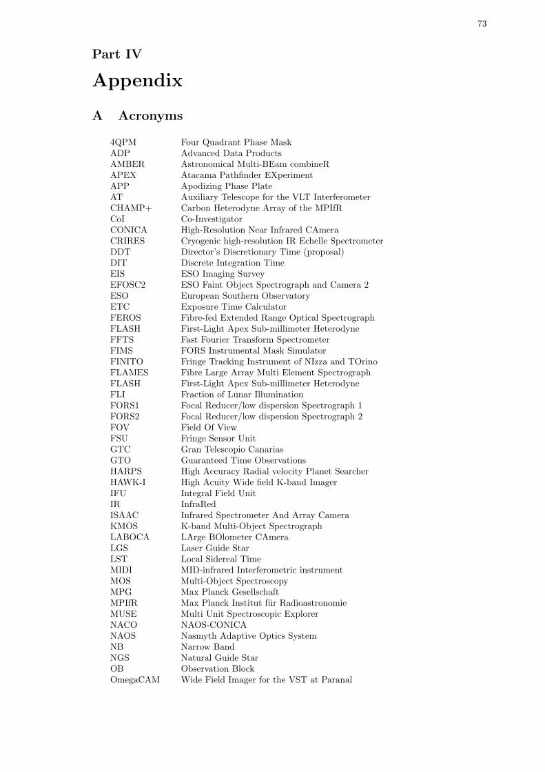
73
Part IV
Appendix
A Acronyms
4QPM Four Quadrant Phase MaskADP Advanced Data ProductsAMBER Astronomical Multi-BEam combineRAPEX Atacama Pathfinder EXperimentAPP Apodizing Phase PlateAT Auxiliary Telescope for the VLT InterferometerCHAMP+ Carbon Heterodyne Array of the MPIfRCoI Co-InvestigatorCONICA High-Resolution Near Infrared CAmeraCRIRES Cryogenic high-resolution IR Echelle SpectrometerDDT Director’s Discretionary Time (proposal)DIT Discrete Integration TimeEIS ESO Imaging SurveyEFOSC2 ESO Faint Object Spectrograph and Camera 2ESO European Southern ObservatoryETC Exposure Time CalculatorFEROS Fibre-fed Extended Range Optical SpectrographFLASH First-Light Apex Sub-millimeter HeterodyneFFTS Fast Fourier Transform SpectrometerFIMS FORS Instrumental Mask SimulatorFINITO Fringe Tracking Instrument of NIzza and TOrinoFLAMES Fibre Large Array Multi Element SpectrographFLASH First-Light Apex Sub-millimeter HeterodyneFLI Fraction of Lunar IlluminationFORS1 Focal Reducer/low dispersion Spectrograph 1FORS2 Focal Reducer/low dispersion Spectrograph 2FOV Field Of ViewFSU Fringe Sensor UnitGTC Gran Telescopio CanariasGTO Guaranteed Time ObservationsHARPS High Accuracy Radial velocity Planet SearcherHAWK-I High Acuity Wide field K-band ImagerIFU Integral Field UnitIR InfraRedISAAC Infrared Spectrometer And Array CameraKMOS K-band Multi-Object SpectrographLABOCA LArge BOlometer CAmeraLGS Laser Guide StarLST Local Sidereal TimeMIDI MID-infrared Interferometric instrumentMOS Multi-Object SpectroscopyMPG Max Planck GesellschaftMPIfR Max Planck Institut fur RadioastronomieMUSE Multi Unit Spectroscopic ExplorerNACO NAOS-CONICANAOS Nasmyth Adaptive Optics SystemNB Narrow BandNGS Natural Guide StarOB Observation BlockOmegaCAM Wide Field Imager for the VST at Paranal
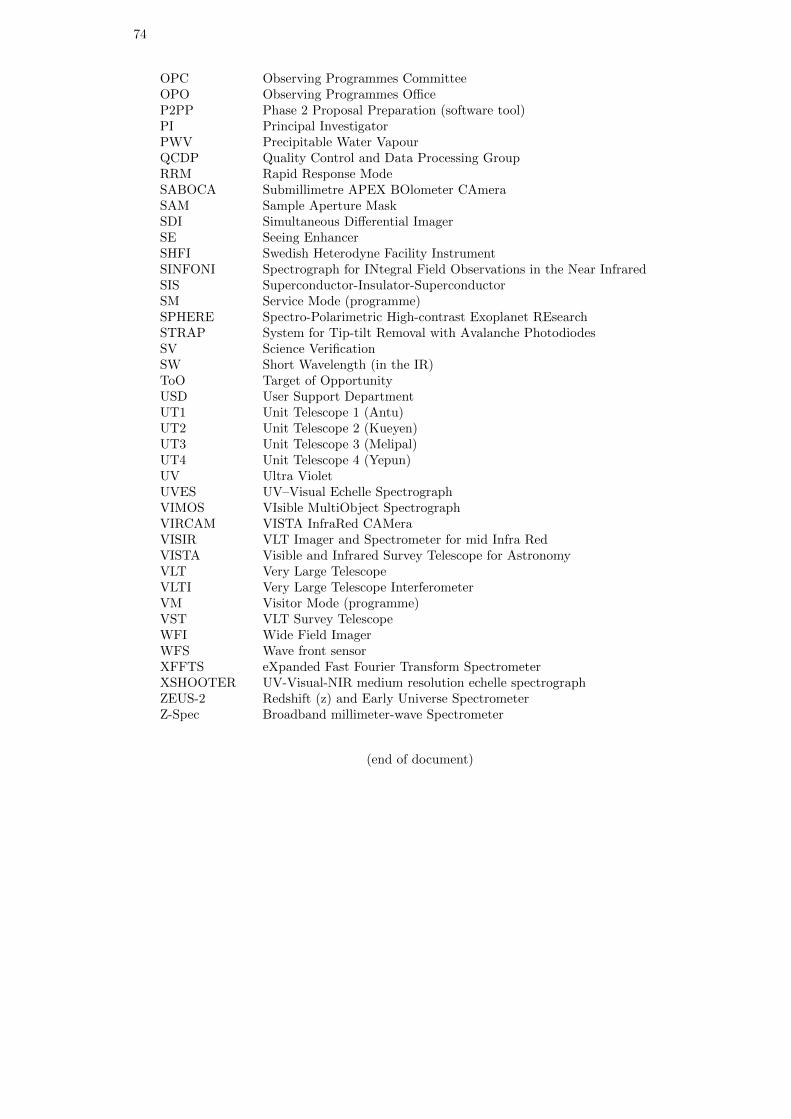
74
OPC Observing Programmes CommitteeOPO Observing Programmes OfficeP2PP Phase 2 Proposal Preparation (software tool)PI Principal InvestigatorPWV Precipitable Water VapourQCDP Quality Control and Data Processing GroupRRM Rapid Response ModeSABOCA Submillimetre APEX BOlometer CAmeraSAM Sample Aperture MaskSDI Simultaneous Differential ImagerSE Seeing EnhancerSHFI Swedish Heterodyne Facility InstrumentSINFONI Spectrograph for INtegral Field Observations in the Near InfraredSIS Superconductor-Insulator-SuperconductorSM Service Mode (programme)SPHERE Spectro-Polarimetric High-contrast Exoplanet REsearchSTRAP System for Tip-tilt Removal with Avalanche PhotodiodesSV Science VerificationSW Short Wavelength (in the IR)ToO Target of OpportunityUSD User Support DepartmentUT1 Unit Telescope 1 (Antu)UT2 Unit Telescope 2 (Kueyen)UT3 Unit Telescope 3 (Melipal)UT4 Unit Telescope 4 (Yepun)UV Ultra VioletUVES UV–Visual Echelle SpectrographVIMOS VIsible MultiObject SpectrographVIRCAM VISTA InfraRed CAMeraVISIR VLT Imager and Spectrometer for mid Infra RedVISTA Visible and Infrared Survey Telescope for AstronomyVLT Very Large TelescopeVLTI Very Large Telescope InterferometerVM Visitor Mode (programme)VST VLT Survey TelescopeWFI Wide Field ImagerWFS Wave front sensorXFFTS eXpanded Fast Fourier Transform SpectrometerXSHOOTER UV-Visual-NIR medium resolution echelle spectrographZEUS-2 Redshift (z) and Early Universe SpectrometerZ-Spec Broadband millimeter-wave Spectrometer
(end of document)