Embed Size (px)
Citation preview
ESP32 Environment Sensor Shield Hookup Guide
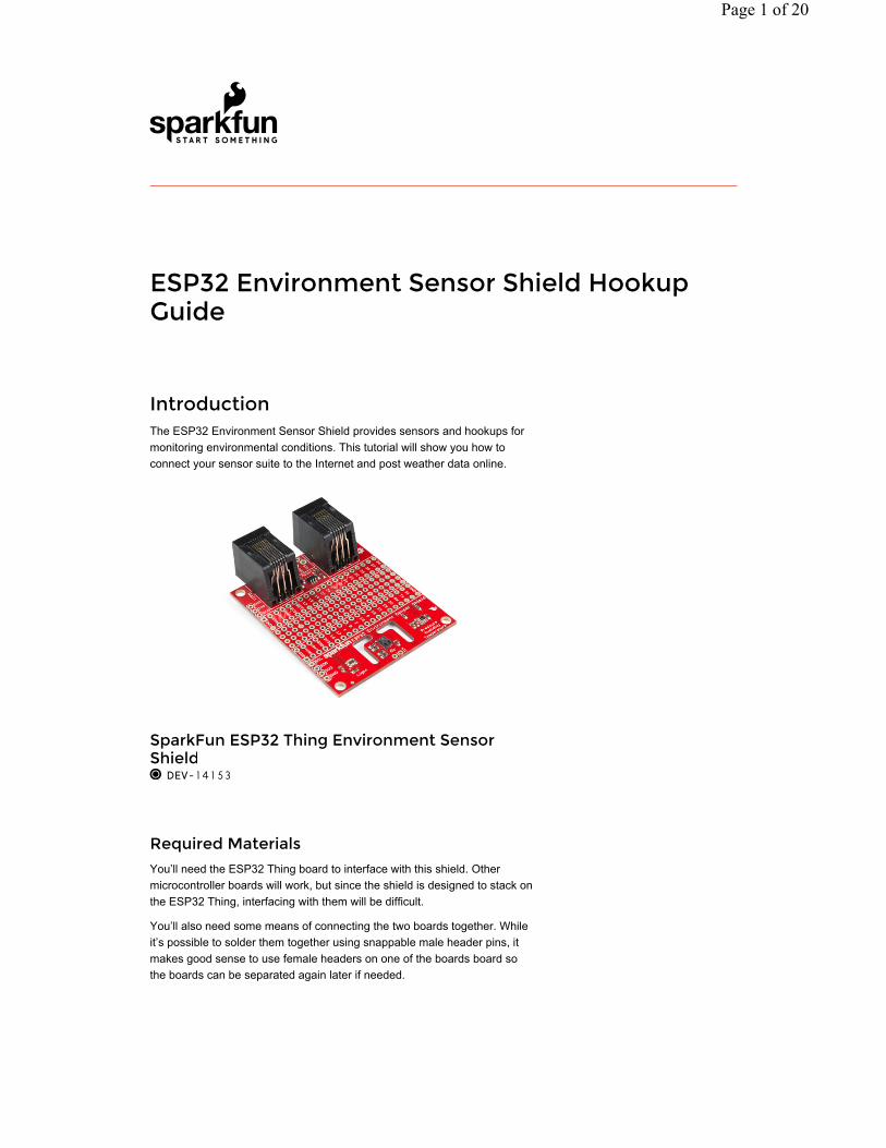
IntroductionThe ESP32 Environment Sensor Shield provides sensors and hookups for monitoring environmental conditions. This tutorial will show you how to connect your sensor suite to the Internet and post weather data online.
Required Materials
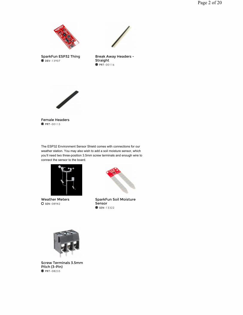
You’ll need the ESP32 Thing board to interface with this shield. Other microcontroller boards will work, but since the shield is designed to stack on the ESP32 Thing, interfacing with them will be difficult.
You’ll also need some means of connecting the two boards together. While it’s possible to solder them together using snappable male header pins, it makes good sense to use female headers on one of the boards board so the boards can be separated again later if needed.
SparkFun ESP32 Thing Environment Sensor Shield DEV-14153
Page 1 of 20
The ESP32 Environment Sensor Shield comes with connections for our weather station. You may also wish to add a soil moisture sensor, which you’ll need two three-position 3.5mm screw terminals and enough wire to connect the sensor to the board.
SparkFun ESP32 Thing DEV-13907
Break Away Headers - Straight PRT-00116
Female Headers PRT-00115
Weather Meters SEN-08942
SparkFun Soil Moisture Sensor SEN-13322
Screw Terminals 3.5mm Pitch (3-Pin) PRT-08235
Page 2 of 20
Tools
At a minimum, you’ll need a soldering iron and some solder. You may need a small screwdriver for attaching the wire to the screw terminals between the soil moisture sensor and the sensor shield. Our pocket screwdriver and screwdriver kit both have bits that will work wonderfully for that purpose. They’re also just handy to keep around!
Suggested Reading
If you have not yet used the ESP32 Thing Development Board, check out this guide first.
If you aren’t familiar with the following concepts, we recommend checking
Soldering Iron - 30W (US, 110V) TOL-09507
Solder Lead Free - 15-gram Tube TOL-09163
Tool Kit - Screwdriver and Bit Set TOL-10865
Pocket Screwdriver Set TOL-12891
ESP32 Thing Hookup GuideOCTOBER 27, 2016
An introduction to the ESP32 Thing's hardware features, and a primer on using the WiFi/Bluetooth system-on-chip in Arduino.
Page 3 of 20
out these tutorials before continuing.
Hardware OverviewThe ESP32 Environment Sensor Shield incorporates three sensors capable of measuring five different environmental variables. It also provides connections for several other sensors that can be connected if so desired.
Onboard Sensors
All of the onboard sensors are connected to the ESP32 via I C connection.
Pressure, Humidity, and Temperature
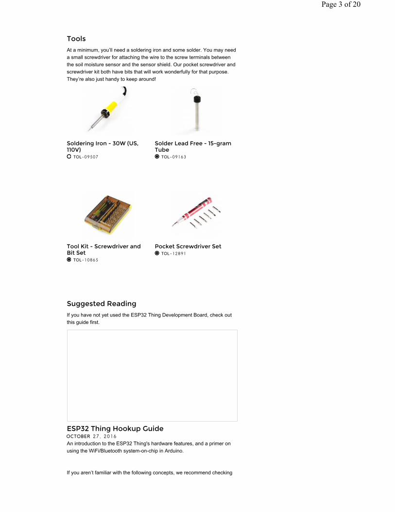
The first onboard sensor is a Bosch BME280. This sensor measures relative humidity, temperature, and barometric pressure. On the back side of the board is a solder jumper (labeled JP1) which can be closed to change the I C address of the chip. By default the address is 0x77; closing the jumper forces the address to 0x76.
How to Solder: Through-Hole SolderingThis tutorial covers everything you need to know about through-hole soldering.
Analog to Digital ConversionThe world is analog. Use analog to digital conversion to help digital devices interpret the world.
I2CAn introduction to I2C, one of the main embedded communications protocols in use today.
2
2
Page 4 of 20
Air Quality and Temperature
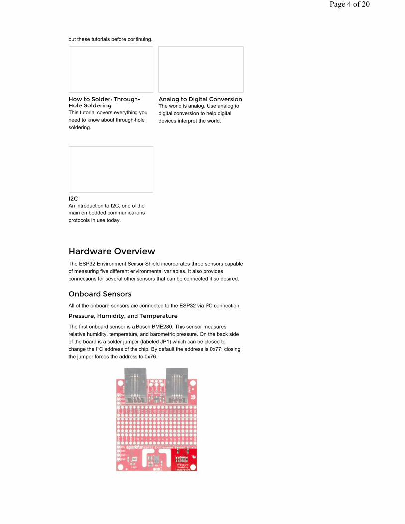
Next is the ams CCS811 air quality and temperature sensor. Note the routed out region around this sensor. That provides a buffer against thermal changes stimulated by the circuitry on the rest of the PCB. As with the BME280, it is possible to change the I C address of this sensor. Closing jumper JP2 on the reverse side of the board causes the sensor to adopt address 0x5A, and by default it will be 0x5B.
Luminosity
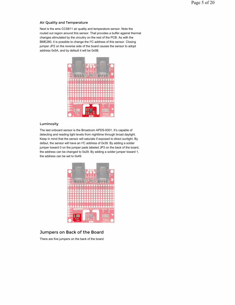
The last onboard sensor is the Broadcom APDS-9301. It’s capable of detecting and reading light levels from nighttime through broad daylight. Keep in mind that the sensor will saturate if exposed to direct sunlight. By defaul, the sensor will have an I C address of 0x39. By adding a solder jumper toward 0 on the jumper pads labeled JP3 on the back of the board, the address can be changed to 0x29. By adding a solder jumper toward 1, the address can be set to 0x49.
Jumpers on Back of the Board
There are five jumpers on the back of the board.
2
2
Page 5 of 20
Here’s what they do:
JP1 - Close this jumper with a solder blob to change the I2C address of the BME280 sensor from 0x77 to 0x76.JP2 - Close this jumper with a solder blob to change the I2C address of the CCS811 sensor from 0x5B to 0x5A.JP3 - Close the 0 half of this jumper with a solder blob to set the address of the APDS-9301 sensor to 0x29. Close the 1 half of this jumper to set the address to 0x49. If you accidentally bridge the entire jumper, the address will be 0x29, but nothing bad will happen.JP4 - Cut this trace to disable the onboard NTC thermistor used by the CCS811 for temperature compensation. If you do this, you must add an external NTC thermistor for the CCS811 to work properly.JP5 - Cut the traces on this jumper to disable the pull-up resistors for the I2C bus.
Optional, off-board Sensors
There are connections for five off-board sensors as well: wind speed and direction, rainfall amount, temperature, and soil moisture.
Wind Speed and Direction
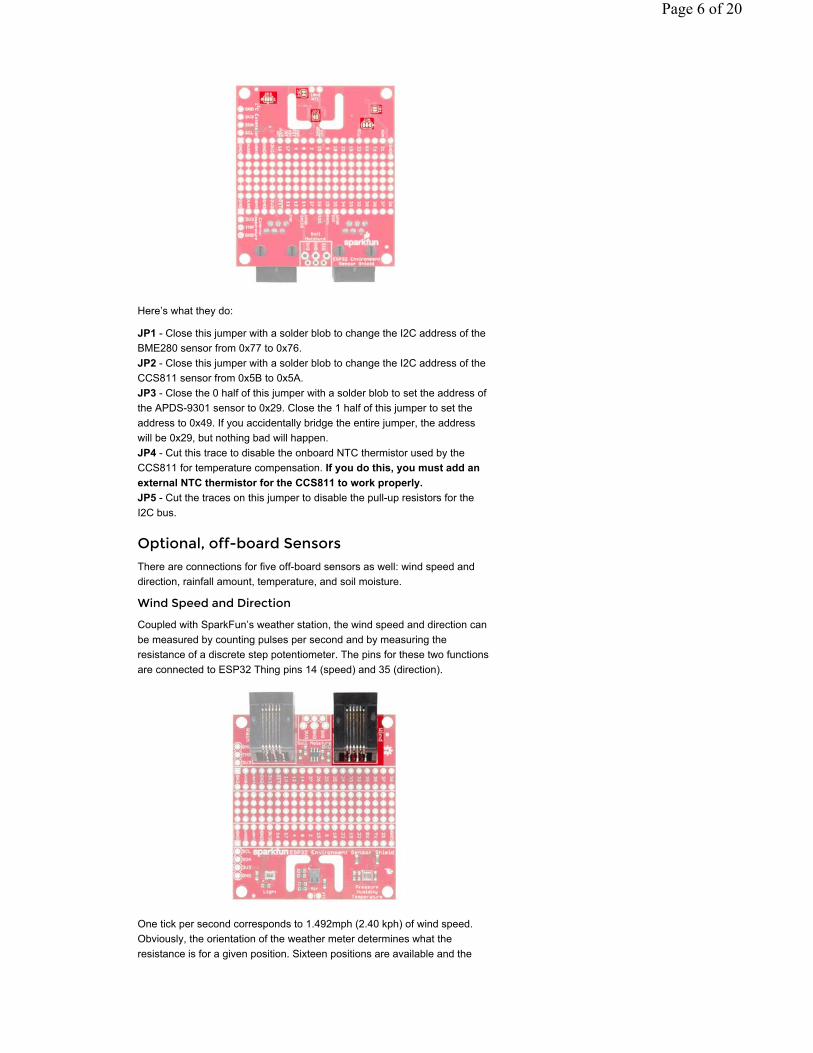
Coupled with SparkFun’s weather station, the wind speed and direction can be measured by counting pulses per second and by measuring the resistance of a discrete step potentiometer. The pins for these two functions are connected to ESP32 Thing pins 14 (speed) and 35 (direction).
One tick per second corresponds to 1.492mph (2.40 kph) of wind speed. Obviously, the orientation of the weather meter determines what the resistance is for a given position. Sixteen positions are available and the
Page 6 of 20
voltage corresponding to each can be found on page 2 of the weather meter’s datasheet. Our example code provides you with a solid example on using the direction sensor, as well.
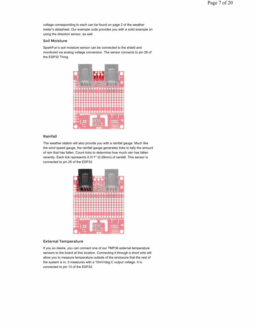
Soil Moisture
SparkFun’s soil moisture sensor can be connected to the shield and monitored via analog voltage conversion. The sensor connects to pin 26 of the ESP32 Thing.
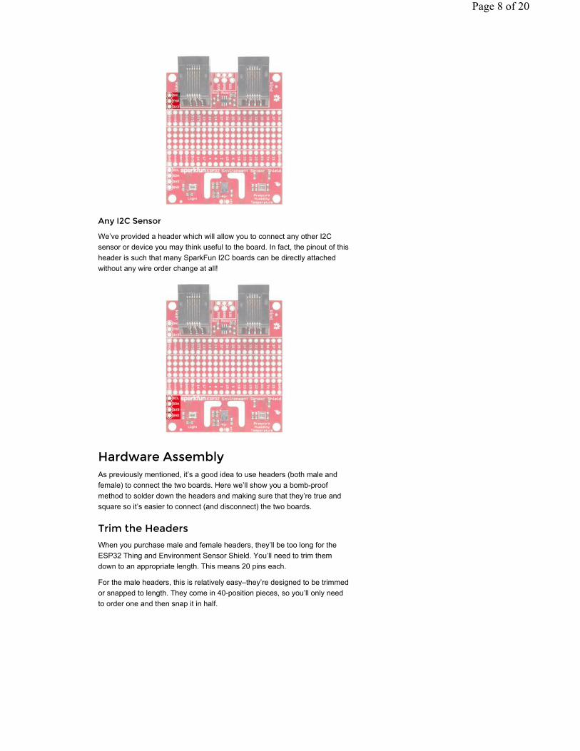
Rainfall
The weather station will also provide you with a rainfall gauge. Much like the wind speed gauge, the rainfall gauge generates ticks to tally the amount of rain that has fallen. Count ticks to determine how much rain has fallen recently. Each tick represents 0.011" (0.28mm) of rainfall. This sensor is connected to pin 25 of the ESP32.
External Temperature
If you so desire, you can connect one of our TMP36 external temperature sensors to the board at this location. Connecting it through a short wire will allow you to measure temperature outisde of the enclosure that the rest of the system is in. It measures with a 10mV/deg C output voltage. It is connected to pin 13 of the ESP32.
Page 7 of 20
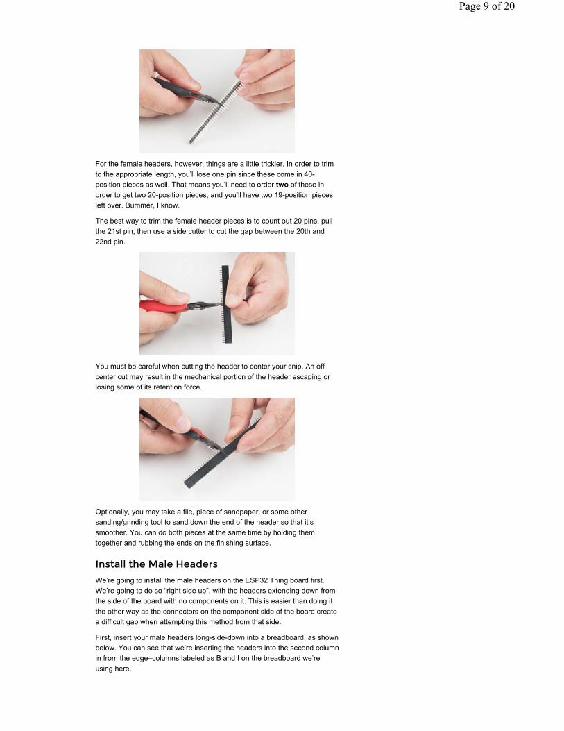
Any I2C Sensor
We’ve provided a header which will allow you to connect any other I2C sensor or device you may think useful to the board. In fact, the pinout of this header is such that many SparkFun I2C boards can be directly attached without any wire order change at all!
Hardware AssemblyAs previously mentioned, it’s a good idea to use headers (both male and female) to connect the two boards. Here we’ll show you a bomb-proof method to solder down the headers and making sure that they’re true and square so it’s easier to connect (and disconnect) the two boards.
Trim the Headers
When you purchase male and female headers, they’ll be too long for the ESP32 Thing and Environment Sensor Shield. You’ll need to trim them down to an appropriate length. This means 20 pins each.
For the male headers, this is relatively easy–they’re designed to be trimmed or snapped to length. They come in 40-position pieces, so you’ll only need to order one and then snap it in half.
Page 8 of 20
For the female headers, however, things are a little trickier. In order to trim to the appropriate length, you’ll lose one pin since these come in 40-position pieces as well. That means you’ll need to order two of these in order to get two 20-position pieces, and you’ll have two 19-position pieces left over. Bummer, I know.
The best way to trim the female header pieces is to count out 20 pins, pull the 21st pin, then use a side cutter to cut the gap between the 20th and 22nd pin.
You must be careful when cutting the header to center your snip. An off center cut may result in the mechanical portion of the header escaping or losing some of its retention force.
Optionally, you may take a file, piece of sandpaper, or some other sanding/grinding tool to sand down the end of the header so that it’s smoother. You can do both pieces at the same time by holding them together and rubbing the ends on the finishing surface.
Install the Male Headers
We’re going to install the male headers on the ESP32 Thing board first. We’re going to do so “right side up”, with the headers extending down from the side of the board with no components on it. This is easier than doing it the other way as the connectors on the component side of the board create a difficult gap when attempting this method from that side.
First, insert your male headers long-side-down into a breadboard, as shown below. You can see that we’re inserting the headers into the second column in from the edge–columns labeled as B and I on the breadboard we’re using here.
Page 9 of 20
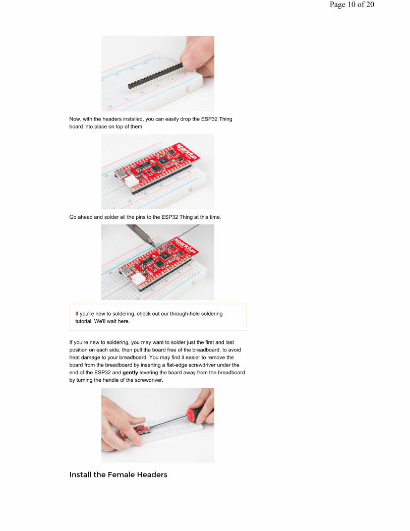
Now, with the headers installed, you can easily drop the ESP32 Thing board into place on top of them.
Go ahead and solder all the pins to the ESP32 Thing at this time.
If you're new to soldering, check out our through-hole soldering tutorial. We'll wait here.
If you’re new to soldering, you may want to solder just the first and last position on each side, then pull the board free of the breadboard, to avoid heat damage to your breadboard. You may find it easier to remove the board from the breadboard by inserting a flat-edge screwdriver under the end of the ESP32 and gently levering the board away from the breadboard by turning the handle of the screwdriver.
Install the Female Headers
Page 10 of 20
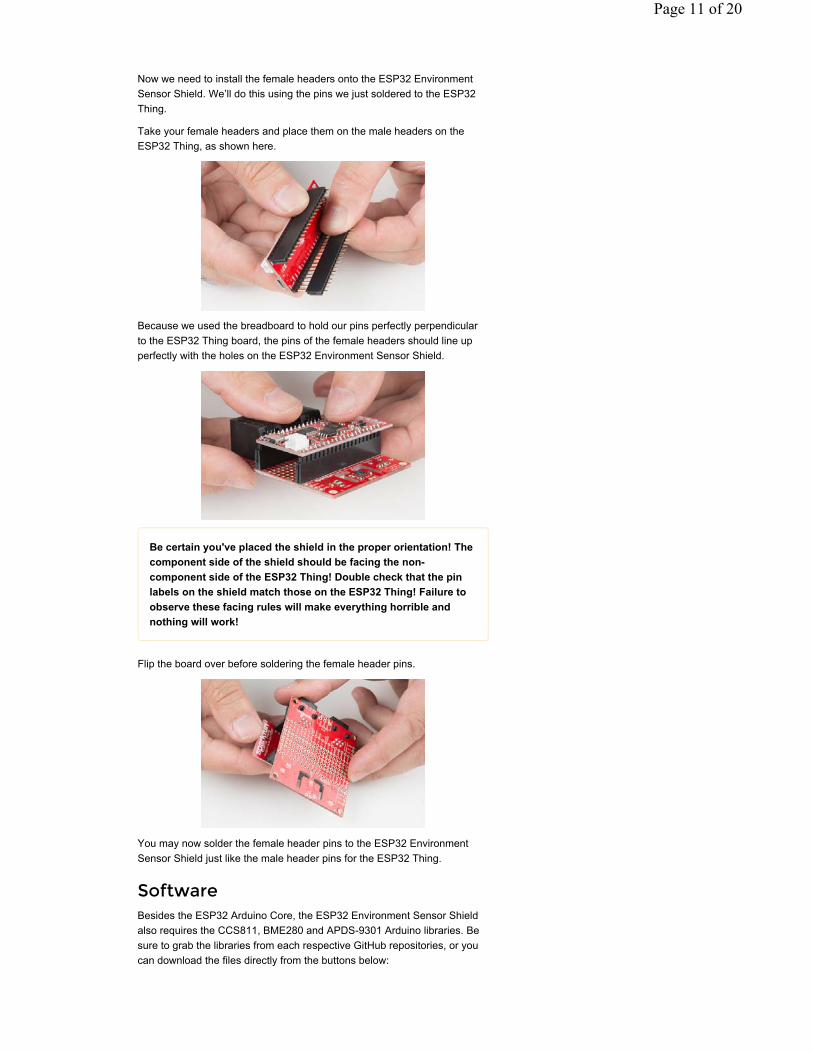
Now we need to install the female headers onto the ESP32 Environment Sensor Shield. We’ll do this using the pins we just soldered to the ESP32 Thing.
Take your female headers and place them on the male headers on the ESP32 Thing, as shown here.
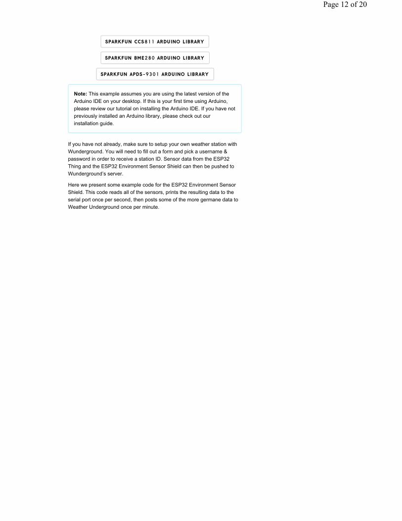
Because we used the breadboard to hold our pins perfectly perpendicular to the ESP32 Thing board, the pins of the female headers should line up perfectly with the holes on the ESP32 Environment Sensor Shield.
Be certain you've placed the shield in the proper orientation! The component side of the shield should be facing the non-component side of the ESP32 Thing! Double check that the pin labels on the shield match those on the ESP32 Thing! Failure to observe these facing rules will make everything horrible and nothing will work!
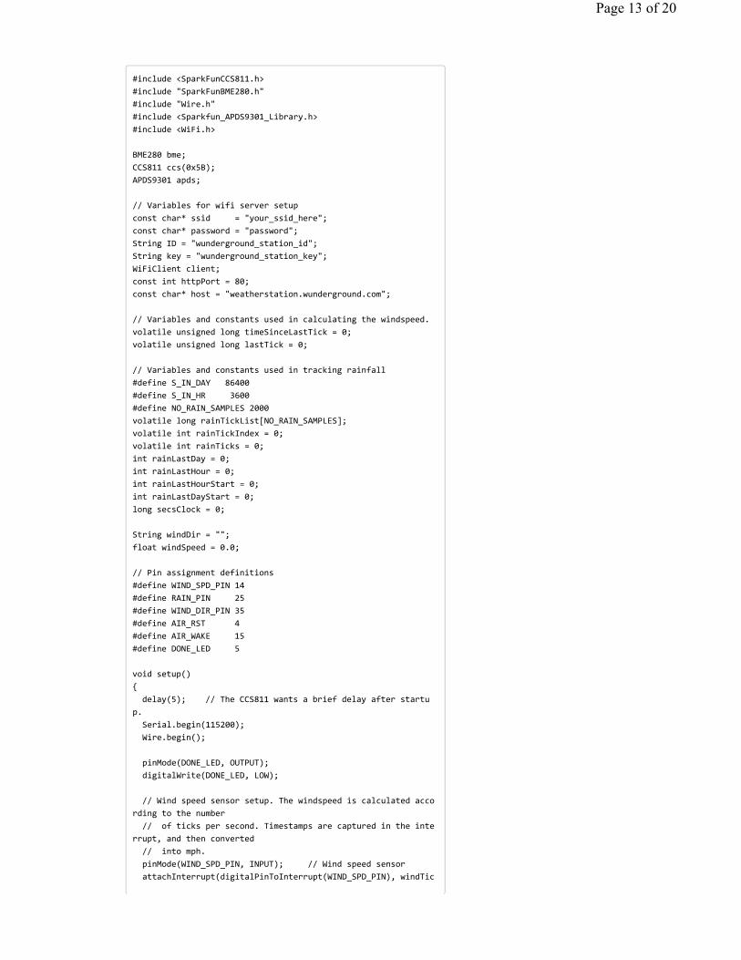
Flip the board over before soldering the female header pins.
You may now solder the female header pins to the ESP32 Environment Sensor Shield just like the male header pins for the ESP32 Thing.
SoftwareBesides the ESP32 Arduino Core, the ESP32 Environment Sensor Shield also requires the CCS811, BME280 and APDS-9301 Arduino libraries. Be sure to grab the libraries from each respective GitHub repositories, or you can download the files directly from the buttons below:
Page 11 of 20
SPARKFUN CCS811 ARDUINO LIBRARY
SPARKFUN BME280 ARDUINO LIBRARY
SPARKFUN APDS-9301 ARDUINO LIBRARY
Note: This example assumes you are using the latest version of the Arduino IDE on your desktop. If this is your first time using Arduino, please review our tutorial on installing the Arduino IDE. If you have not previously installed an Arduino library, please check out our installation guide.
If you have not already, make sure to setup your own weather station with Wunderground. You will need to fill out a form and pick a username & password in order to receive a station ID. Sensor data from the ESP32 Thing and the ESP32 Environment Sensor Shield can then be pushed to Wunderground’s server.
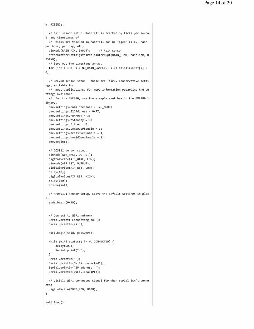
Here we present some example code for the ESP32 Environment Sensor Shield. This code reads all of the sensors, prints the resulting data to the serial port once per second, then posts some of the more germane data to Weather Underground once per minute.
Page 12 of 20
#include <SparkFunCCS811.h>#include "SparkFunBME280.h"#include "Wire.h"#include <Sparkfun_APDS9301_Library.h>#include <WiFi.h>
BME280 bme; CCS811 ccs(0x5B);APDS9301 apds;
// Variables for wifi server setup const char* ssid = "your_ssid_here";const char* password = "password"; String ID = "wunderground_station_id";String key = "wunderground_station_key"; WiFiClient client; const int httpPort = 80;const char* host = "weatherstation.wunderground.com";
// Variables and constants used in calculating the windspeed.volatile unsigned long timeSinceLastTick = 0;volatile unsigned long lastTick = 0;
// Variables and constants used in tracking rainfall#define S_IN_DAY 86400#define S_IN_HR 3600#define NO_RAIN_SAMPLES 2000volatile long rainTickList[NO_RAIN_SAMPLES];volatile int rainTickIndex = 0;volatile int rainTicks = 0;int rainLastDay = 0;int rainLastHour = 0;int rainLastHourStart = 0;int rainLastDayStart = 0;long secsClock = 0;
String windDir = "";float windSpeed = 0.0;
// Pin assignment definitions#define WIND_SPD_PIN 14#define RAIN_PIN 25#define WIND_DIR_PIN 35#define AIR_RST 4#define AIR_WAKE 15#define DONE_LED 5
void setup() { delay(5); // The CCS811 wants a brief delay after startu
p. Serial.begin(115200); Wire.begin();
pinMode(DONE_LED, OUTPUT);digitalWrite(DONE_LED, LOW);
// Wind speed sensor setup. The windspeed is calculated according to the number// of ticks per second. Timestamps are captured in the inte
rrupt, and then converted// into mph. pinMode(WIND_SPD_PIN, INPUT); // Wind speed sensorattachInterrupt(digitalPinToInterrupt(WIND_SPD_PIN), windTic
Page 13 of 20
k, RISING);
// Rain sesnor setup. Rainfall is tracked by ticks per second, and timestamps of// ticks are tracked so rainfall can be "aged" (i.e., rain
per hour, per day, etc)pinMode(RAIN_PIN, INPUT); // Rain sensorattachInterrupt(digitalPinToInterrupt(RAIN_PIN), rainTick, R
ISING); // Zero out the timestamp array.for (int i = 0; i < NO_RAIN_SAMPLES; i++) rainTickList[i] =
0;
// BME280 sensor setup these are fairly conservative settings, suitable for// most applications. For more information regarding the se
ttings available// for the BME280, see the example sketches in the BME280 l
ibrary. bme.settings.commInterface = I2C_MODE; bme.settings.I2CAddress = 0x77; bme.settings.runMode = 3; bme.settings.tStandby = 0; bme.settings.filter = 0; bme.settings.tempOverSample = 1; bme.settings.pressOverSample = 1; bme.settings.humidOverSample = 1; bme.begin();
// CCS811 sensor setup.pinMode(AIR_WAKE, OUTPUT);digitalWrite(AIR_WAKE, LOW);pinMode(AIR_RST, OUTPUT);digitalWrite(AIR_RST, LOW);delay(10);digitalWrite(AIR_RST, HIGH);delay(100);
ccs.begin();
// APDS9301 sensor setup. Leave the default settings in place. apds.begin(0x39);
// Connect to WiFi network Serial.print("Connecting to "); Serial.println(ssid);
WiFi.begin(ssid, password);
while (WiFi.status() != WL_CONNECTED) {delay(500);
Serial.print("."); } Serial.println(""); Serial.println("WiFi connected"); Serial.println("IP address: "); Serial.println(WiFi.localIP());
// Visible WiFi connected signal for when serial isn't connecteddigitalWrite(DONE_LED, HIGH);
}
void loop()
Page 14 of 20
{ static unsigned long outLoopTimer = 0;static unsigned long wundergroundUpdateTimer = 0;static unsigned long clockTimer = 0;static unsigned long tempMSClock = 0;
// Create a seconds clock based on the millis() count. We use this// to track rainfall by the second. We've done this becaus
e the millis()// count overflows eventually, in a way that makes trackin
g time stamps// very difficult.
tempMSClock += millis() clockTimer; clockTimer = millis();
while (tempMSClock >= 1000) { secsClock++; tempMSClock = 1000; }
// This is a oncepersecond timer that calculates and prints off various// values from the sensors attached to the system.if (millis() outLoopTimer >= 2000)
{ outLoopTimer = millis();
Serial.print("\nTimestamp: "); Serial.println(secsClock);
// Windspeed calculation, in mph. timeSinceLastTick gets updated by an
// interrupt when ticks come in from the wind speed sensor.
if (timeSinceLastTick != 0) windSpeed = 1000.0/timeSinceLastTick; Serial.print("Windspeed: "); Serial.print(windSpeed*1.492); Serial.println(" mph");
// Update temperature. This also updates compensation values used to
// calculate other parameters. Serial.print("Temperature: "); Serial.print(bme.readTempF(), 2); Serial.println(" degrees F");
// Display relative humidity. Serial.print("%RH: "); Serial.print(bme.readFloatHumidity(), 2); Serial.println(" %");
// Display pressure. Serial.print("Pres: "); Serial.print(bme.readFloatPressure() * 0.0002953); Serial.println(" in");
// Calculate the wind direction and display it as a string. Serial.print("Wind dir: ");
windDirCalc(analogRead(WIND_DIR_PIN)); Serial.print(" "); Serial.println(windDir);
Page 15 of 20
// Calculate and display rainfall totals. Serial.print("Rainfall last hour: "); Serial.println(float(rainLastHour)*0.011, 3); Serial.print("Rainfall last day: "); Serial.println(float(rainLastDay)*0.011, 3); Serial.print("Rainfall to date: "); Serial.println(float(rainTicks)*0.011, 3);
// Trigger the CCS811's internal update procedure, then// dump the values to the serial port.
ccs.readAlgorithmResults();
Serial.print("CO2: "); Serial.println(ccs.getCO2());
Serial.print("tVOC: "); Serial.println(ccs.getTVOC());
Serial.print("Luminous flux: "); Serial.println(apds.readLuxLevel(),6);
// Calculate the amount of rain in the last day and hour. rainLastHour = 0; rainLastDay = 0;
// If there are any captured rain sensor ticks...if (rainTicks > 0)
{ // Start at the end of the list. rainTickIndex will alwa
ys be one greater// than the number of captured samples.int i = rainTickIndex1;
// Iterate over the list and count up the number of samples that have been
// captured with time stamps in the last hour.while ((rainTickList[i] >= secsClock S_IN_HR) && rainT
ickList[i] != 0) { i;
if (i < 0) i = NO_RAIN_SAMPLES1; rainLastHour++; }
// Repeat the process, this time over days. i = rainTickIndex1;
while ((rainTickList[i] >= secsClock S_IN_DAY) && rainTickList[i] != 0) { i;
if (i < 0) i = NO_RAIN_SAMPLES1; rainLastDay++; } rainLastDayStart = i; } }
// Update wunderground once every sixty seconds.if (millis() wundergroundUpdateTimer >= 60000)
{
wundergroundUpdateTimer = millis();// Set up the generic useeverytime part of the URLString url = "/weatherstation/updateweatherstation.php";
url += "?ID="; url += ID;
Page 16 of 20
url += "&PASSWORD="; url += key; url += "&dateutc=now&action=updateraw";
// Now let's add in the data that we've collected from our sensors
// Start with rain in last hour/day url += "&rainin="; url += rainLastHour; url += "&dailyrainin="; url += rainLastDay;
// Next let's do wind url += "&winddir="; url += windDir; url += "&windspeedmph="; url += windSpeed;
// Now for temperature, pressure and humidity. url += "&tempf="; url += bme.readTempF(); url += "&humidity="; url += bme.readFloatHumidity(); url += "&baromin=";
float baromin = 0.0002953 * bme.readFloatPressure(); url += baromin;
// Connnect to Weather Underground. If the connection fails, return from
// loop and start over again.if (!client.connect(host, httpPort))
{ Serial.println("Connection failed");
return; }
else { Serial.println("Connection succeeded"); }
// Issue the GET command to Weather Underground to post the data we've
// collected. client.print(String("GET ") + url + " HTTP/1.1\r\n" +
"Host: " + host + "\r\n" +"Connection: close\r\n\r\n");
// Give Weather Underground five seconds to reply.unsigned long timeout = millis();while (client.available() == 0)
{ if (millis() timeout > 5000)
{ Serial.println(">>> Client Timeout !"); client.stop();
return; } }
// Read the response from Weather Underground and print it to the console.
while(client.available()) {
String line = client.readStringUntil('\r'); Serial.print(line);
Page 17 of 20
} } }
// Keep track of when the last tick came in on the wind sensor.void windTick(void){ timeSinceLastTick = millis() lastTick; lastTick = millis();}
// Capture timestamp of when the rain sensor got tripped.void rainTick(void){ rainTickList[rainTickIndex++] = secsClock;if (rainTickIndex == NO_RAIN_SAMPLES) rainTickIndex = 0;
rainTicks++;}
// For the purposes of this calculation, 0deg is when the wind vane// is pointed at the anemometer. The angle increases in a clockwise// manner from there.void windDirCalc(int vin){ if (vin < 150) windDir="202.5";else if (vin < 300) windDir = "180";else if (vin < 400) windDir = "247.5";else if (vin < 600) windDir = "225";else if (vin < 900) windDir = "292.5";else if (vin < 1100) windDir = "270";else if (vin < 1500) windDir = "112.5";else if (vin < 1700) windDir = "135";else if (vin < 2250) windDir = "337.5";else if (vin < 2350) windDir = "315";else if (vin < 2700) windDir = "67.5";else if (vin < 3000) windDir = "90";else if (vin < 3200) windDir = "22.5";else if (vin < 3400) windDir = "45";else if (vin < 4000) windDir = "0";else windDir = "0";
}
Note: When connecting to a WiFi network and the Wunderground server, make sure to modify the variables ssid , password , ID , and key .
Expected output
Here is a picture of what you should expect upon starting up your ESP32 and letting it connect to WiFi:
Page 18 of 20
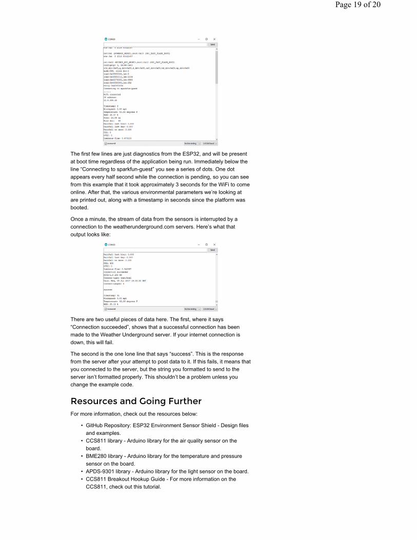
The first few lines are just diagnostics from the ESP32, and will be present at boot time regardless of the application being run. Immediately below the line “Connecting to sparkfun-guest” you see a series of dots. One dot appears every half second while the connection is pending, so you can see from this example that it took approximately 3 seconds for the WiFi to come online. After that, the various environmental parameters we’re looking at are printed out, along with a timestamp in seconds since the platform was booted.
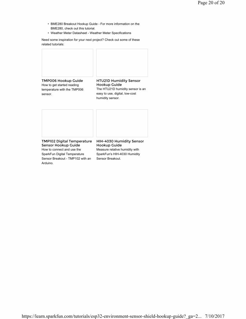
Once a minute, the stream of data from the sensors is interrupted by a connection to the weatherunderground.com servers. Here’s what that output looks like:
There are two useful pieces of data here. The first, where it says “Connection succeeded”, shows that a successful connection has been made to the Weather Underground server. If your internet connection is down, this will fail.
The second is the one lone line that says “success”. This is the response from the server after your attempt to post data to it. If this fails, it means that you connected to the server, but the string you formatted to send to the server isn’t formatted properly. This shouldn’t be a problem unless you change the example code.
Resources and Going FurtherFor more information, check out the resources below:
• GitHub Repository: ESP32 Environment Sensor Shield - Design files and examples.
• CCS811 library - Arduino library for the air quality sensor on the board.
• BME280 library - Arduino library for the temperature and pressure sensor on the board.
• APDS-9301 library - Arduino library for the light sensor on the board.• CCS811 Breakout Hookup Guide - For more information on the
CCS811, check out this tutorial.
Page 19 of 20
• BME280 Breakout Hookup Guide - For more information on the BME280, check out this tutorial.
• Weather Meter Datasheet - Weather Meter Specifications
Need some inspiration for your next project? Check out some of these related tutorials:
TMP006 Hookup GuideHow to get started reading temperature with the TMP006 sensor.
HTU21D Humidity Sensor Hookup GuideThe HTU21D humidity sensor is an easy to use, digital, low-cost humidity sensor.
TMP102 Digital Temperature Sensor Hookup GuideHow to connect and use the SparkFun Digital Temperature Sensor Breakout - TMP102 with an Arduino.
HIH-4030 Humidity Sensor Hookup GuideMeasure relative humidity with SparkFun's HIH-4030 Humidity Sensor Breakout.
Page 20 of 20
7/10/2017https://learn.sparkfun.com/tutorials/esp32-environment-sensor-shield-hookup-guide?_ga=2...