Embed Size (px)
Citation preview
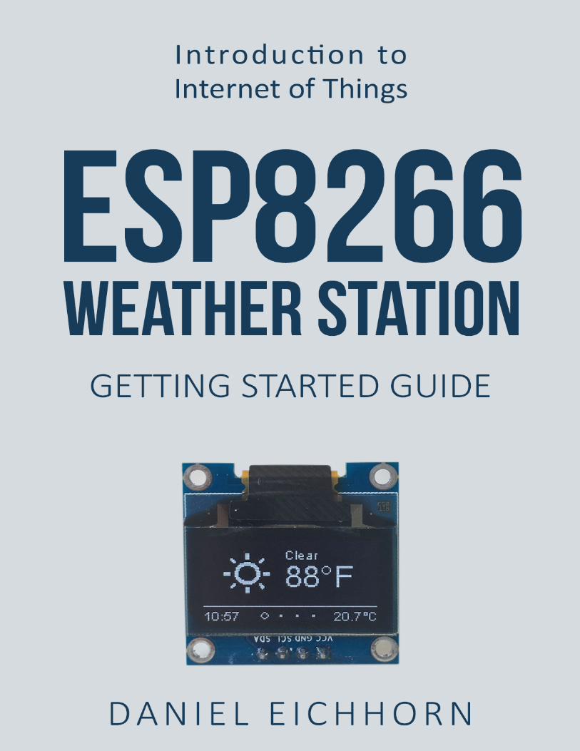

ESP8266 Weather StationGetting Started Guide
Daniel Eichhorn
This book is for sale at http://leanpub.com/esp8266weatherstationgettingstartedguide
This version was published on 2017-06-08
This is a Leanpub book. Leanpub empowers authors and publishers with the Lean Publishingprocess. Lean Publishing is the act of publishing an in-progress ebook using lightweight tools andmany iterations to get reader feedback, pivot until you have the right book and build traction onceyou do.
© 2016 - 2017 Daniel Eichhorn

Contents
Introduction . . . . . . . . . . . . . . . . . . . . . . . . . . . . . . . . . . . . . . . . . . . . 1
Required Hardware . . . . . . . . . . . . . . . . . . . . . . . . . . . . . . . . . . . . . . . . 3ESP8266 Module . . . . . . . . . . . . . . . . . . . . . . . . . . . . . . . . . . . . . . . . 3OLED Display . . . . . . . . . . . . . . . . . . . . . . . . . . . . . . . . . . . . . . . . . 4Wires & Cables . . . . . . . . . . . . . . . . . . . . . . . . . . . . . . . . . . . . . . . . 4
Tool Setup . . . . . . . . . . . . . . . . . . . . . . . . . . . . . . . . . . . . . . . . . . . . . 6Download and Install the Serial Driver . . . . . . . . . . . . . . . . . . . . . . . . . . . . 6The Arduino IDE . . . . . . . . . . . . . . . . . . . . . . . . . . . . . . . . . . . . . . . 7Install the ESP8266 tool chain . . . . . . . . . . . . . . . . . . . . . . . . . . . . . . . . . 7Testing the Setup: WiFi Scanner . . . . . . . . . . . . . . . . . . . . . . . . . . . . . . . 9Trouble Shooting . . . . . . . . . . . . . . . . . . . . . . . . . . . . . . . . . . . . . . . . 11Summary . . . . . . . . . . . . . . . . . . . . . . . . . . . . . . . . . . . . . . . . . . . . 13
ESP8266 Programming Basics . . . . . . . . . . . . . . . . . . . . . . . . . . . . . . . . . . 15Preparation . . . . . . . . . . . . . . . . . . . . . . . . . . . . . . . . . . . . . . . . . . . 15The Arduino Sketch . . . . . . . . . . . . . . . . . . . . . . . . . . . . . . . . . . . . . . 15Hello World: The serial console . . . . . . . . . . . . . . . . . . . . . . . . . . . . . . . . 16Input/Output: GPIO pins . . . . . . . . . . . . . . . . . . . . . . . . . . . . . . . . . . . 18Interrupts . . . . . . . . . . . . . . . . . . . . . . . . . . . . . . . . . . . . . . . . . . . . 21Measuring analog signals . . . . . . . . . . . . . . . . . . . . . . . . . . . . . . . . . . . 22WiFi . . . . . . . . . . . . . . . . . . . . . . . . . . . . . . . . . . . . . . . . . . . . . . 22HTTP . . . . . . . . . . . . . . . . . . . . . . . . . . . . . . . . . . . . . . . . . . . . . . 23
The ESP8266 WeatherStation . . . . . . . . . . . . . . . . . . . . . . . . . . . . . . . . . . . 27Installing the libraries . . . . . . . . . . . . . . . . . . . . . . . . . . . . . . . . . . . . . 27Open the Weather Station Example . . . . . . . . . . . . . . . . . . . . . . . . . . . . . . 28Getting the Wunderground API Key . . . . . . . . . . . . . . . . . . . . . . . . . . . . . 28Configuring the Weather Station . . . . . . . . . . . . . . . . . . . . . . . . . . . . . . . 29Connecting the Hardware . . . . . . . . . . . . . . . . . . . . . . . . . . . . . . . . . . . 30First Run . . . . . . . . . . . . . . . . . . . . . . . . . . . . . . . . . . . . . . . . . . . . 32Summary . . . . . . . . . . . . . . . . . . . . . . . . . . . . . . . . . . . . . . . . . . . . 32
CONTENTS
The WeatherStation Code Explained . . . . . . . . . . . . . . . . . . . . . . . . . . . . . . 33The JSON Streaming Parser . . . . . . . . . . . . . . . . . . . . . . . . . . . . . . . . . . 33Conclusion . . . . . . . . . . . . . . . . . . . . . . . . . . . . . . . . . . . . . . . . . . . 36
Collecting and Displaying Local Data . . . . . . . . . . . . . . . . . . . . . . . . . . . . . . 37The Climate Node Setup . . . . . . . . . . . . . . . . . . . . . . . . . . . . . . . . . . . . 37Thingspeak Setup . . . . . . . . . . . . . . . . . . . . . . . . . . . . . . . . . . . . . . . 38Programming the Climate Node . . . . . . . . . . . . . . . . . . . . . . . . . . . . . . . 41Displaying the data on the WeatherStation . . . . . . . . . . . . . . . . . . . . . . . . . . 43
More Projects . . . . . . . . . . . . . . . . . . . . . . . . . . . . . . . . . . . . . . . . . . . 44The ESP8266 PlaneSpotter . . . . . . . . . . . . . . . . . . . . . . . . . . . . . . . . . . . 44The ESP8266 WorldClock . . . . . . . . . . . . . . . . . . . . . . . . . . . . . . . . . . . 45
IntroductionSince the end of 2014 the ESP8266 chip by Chinese manufacturer Espressif has gained a lot ofpopularity in the DIY community, due to its rich set of features but also due to the very attractiveprice. First it was only available as a WiFi extension to existing development boards, cutting theprice of comparable products from USD $60 to a mere $6! Suddenly all the Arduino developershad an affordable way to connect their devices to the internet. Not long after, clever hackers andengineers realized that the ESP8266 could be used beyond the rather simple AT firmware. A softwaredevelopment kit (SDK) was available but badly documented, so they reverse-engineered the SDKand used Google Translate to understand the Chinese manual.
At first the process to set up a development environment was complicated and cumbersome. Fileshad to be downloaded from different sources and copied to various locations. But then several groupsstarted to provide simplifications to this process. One of the first simplifications was the NodeMCULUA firmware which could interpret scripts written in the language LUA at runtime. The firmwarealso provided bindings into Espressif’s API from the LUA language so that the pins of the ESP8266could be easily controlled with just a few lines of code.
A few months later another huge simplification became available: the integration of the C/C++API into the Arduino IDE! Suddenly it was possible to profit from the simplicity of the Arduinoecosystem, which not only provided a vast number of libraries but also made the C programmingstart of your project a lot easier. Since code developed in the Arduino IDE compiled into a veryefficient binary the often scarce resources of the ESP8266 were also used more efficiently. Forinstance, the interpreter (the program that reads and executes scripts) of the LUA firmware neededa lot of memory just for itself and did not leave much for your script code.
After having used the LUA firmware for a while I got frustrated by its instability and lack ofperipheral support. So I just jumped on the possibility to program the ESP8266 from the ArduinoIDE - and I loved it from the beginning. I didn’t have to worry about a complicated tool installation:it was as simple as copying a URL into the right spot in the Arduino IDE. And also many librariesprogrammed for the standard Arduino ATmega chips worked out of the box for the ESP8266 aswell! So I went to work and ported some of the projects I had written for the LUA firmware to theArduino/ESP8266 platform.
However, I was struggling in LUA with one peripheral module I already had successfully working:a wonderfully crisp OLED display. There were several libraries available for the Arduino using thatdisplay but I just couldn’t get them to run: the extremely versatile and rich u8glib used a lot ofATmega specific code and just wouldn’t compile. The Adafruit library on the other hand was madefor slightly different displays and wouldn’t work for me either. So I set out and started to write myown (and very first) library for the Arduino/ESP8266 platform.
To verify the library I implemented a few ideas which involved the OLED display. One of them wasthe ESP8266 WeatherStation. After getting the code to work I wrote a blog post about it and had

Introduction 2
it running somewhere in my apartment - and I forgot about it until I saw that suddenly the visitson that blog post spiked and that many visitors came from Thingiverse. From a 3D printing projectbuilt around my WeatherStation code, that was the moment when I realized that I had somethinginteresting and people had found the WeatherStation appealing.
I decided to provide the right components needed for building the WeatherStation and to sell it asa kit for the ESP8266 WeatherStation. Quickly I had set up a simple PayPal shop on my blog. Asupplier in China would ship the kit directly to buyers all over the world and after a few monthsWeatherStations were being programmed in more than 20 countries.
You are now holding a guide to the WeatherStation in your hands. Thank you for your interest! Youmight have just found this guide on Amazon and you don’t have the hardware yet. Or you havealready acquired the components on your own and are now looking for a guide to use them. Or youhave bought the kit from my shop or my listing on Amazon. In all of these cases you quickly wantto get started with the ESP8266 and I’ve tried very hard to make this as easy as possible for you.Please let me know if you see mistakes. You can reach out to me through [email protected] on Twitter: https://twitter.com/squix78
Also make sure that you subscribe to my newsletter to stay updated with latest news aroundthe ESP8266. You will get a maximum of 1-2 emails per month, I promise! https://blog.squix.org/subscribe
One more thing! If you like this project please have a look at my shop. I recently created a hardwarekit containing a beautiful color display with touch screen. There are are several projects you canbuild with it.
The ESP8266 WiFi Color Display Kit
https://blog.squix.org/product/esp8266-wifi-color-display-kit-2-4
Required HardwareThe Starter Kit is available from two shops. You can buy it from the shop on my blog and shippingis available to almost all destinations: https://blog.squix.org/product-category/starter-kits
If you live in the US you can purchase theWeatherStation fromAmazon (https://www.amazon.com/dp/B01KE7BA3O/) as well. Get a 10% discount by using this code during checkout on the Amazonstore: SKH3MS43
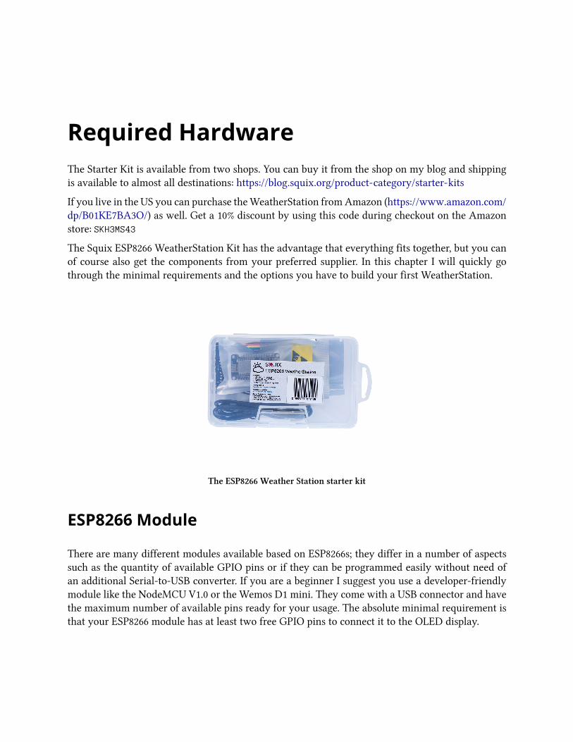
The Squix ESP8266 WeatherStation Kit has the advantage that everything fits together, but you canof course also get the components from your preferred supplier. In this chapter I will quickly gothrough the minimal requirements and the options you have to build your first WeatherStation.
The ESP8266 Weather Station starter kit
ESP8266 Module
There are many different modules available based on ESP8266s; they differ in a number of aspectssuch as the quantity of available GPIO pins or if they can be programmed easily without need ofan additional Serial-to-USB converter. If you are a beginner I suggest you use a developer-friendlymodule like the NodeMCU V1.0 or the Wemos D1 mini. They come with a USB connector and havethe maximum number of available pins ready for your usage. The absolute minimal requirement isthat your ESP8266 module has at least two free GPIO pins to connect it to the OLED display.

Required Hardware 4
OLED Display
With the display you also have many options: do you want the pixels to be white or blue, or doyou even prefer a two color display where the footer is in one color and the rest in another? Whatreally matters is the driver chip and the protocol. The OLED library currently supports I2C and SPIfor both the SSD1306 and the SH1106 chip. The first is often used for 0.96” inch displays while thesecond one is used for 1.3” displays. Displays with SPI interface will consume more of your freeGPIO pins.
The OLED display with a blue and a yellow section
Wires & Cables
You will also need some wires to connect the display to the ESP8266. In case you want to connectthe display directly to the NodeMCU you will need at least four female-to-female jumper wires,since both the display and the NodeMCU have male pin headers. The wires don’t need to be long,4” (10cm) is usually enough.
To program the ESP8266 module you will also need a USB cable. In case of the NodeMCU this cable

Required Hardware 5
should have a micro-USB connector on the module side and a normal USB connector for your PCor Mac.
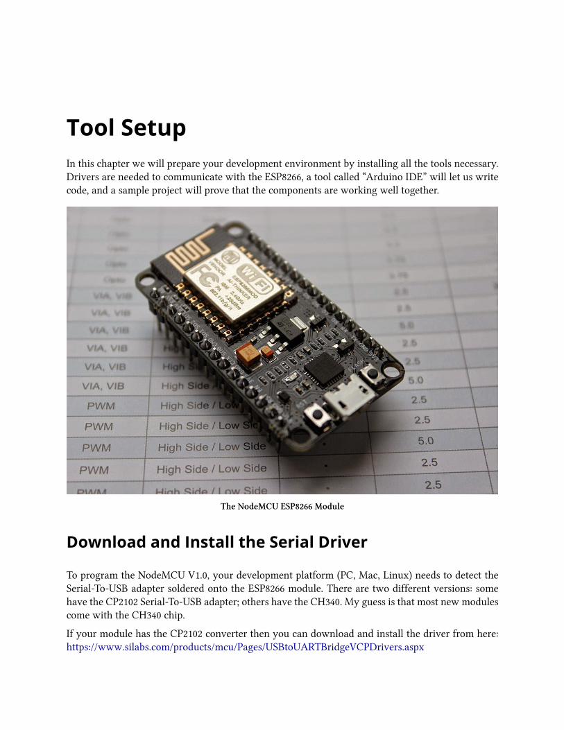
Tool SetupIn this chapter we will prepare your development environment by installing all the tools necessary.Drivers are needed to communicate with the ESP8266, a tool called “Arduino IDE” will let us writecode, and a sample project will prove that the components are working well together.
The NodeMCU ESP8266 Module
Download and Install the Serial Driver
To program the NodeMCU V1.0, your development platform (PC, Mac, Linux) needs to detect theSerial-To-USB adapter soldered onto the ESP8266 module. There are two different versions: somehave the CP2102 Serial-To-USB adapter; others have the CH340. My guess is that most new modulescome with the CH340 chip.
If your module has the CP2102 converter then you can download and install the driver from here:https://www.silabs.com/products/mcu/Pages/USBtoUARTBridgeVCPDrivers.aspx

Tool Setup 7
In case your module comes with a CH340 serial-to-USB converter then download the drivers fromhere:
• Win: http://blog.squix.org/downloads/CH341SER.zip• Mac: https://blog.squix.org/wp-content/uploads/2016/12/CH34x_Install_V1.3.zip
The Arduino IDE
The Arduino Integrated Development Environment (IDE) is the tool you will use to program theESP8266. IDEs are more than just editors; they help you with various tasks during the developmentprocess. For me as a professional software developer the Arduino IDE is not a very powerful one. Itlacks some features that I got used to and I am missing them every time I program for the ESP8266.But the Arduino IDE was not made for professional programmers, it was made with the beginnerin mind and this is also the reason why we will use it here. If you are looking for more convenience,have a look at http://platformio.org/ or the ESP8266 integration into the Eclipse IDE.
To install the Arduino IDE go to https://www.arduino.cc/en/Main/Software and download the latestversion matching your operating system:
• For Mac OS X you can download a ZIP file which you then have to extract. Take the extractedapplication “Arduino” and move it to your Applications folder.
• For Windows you have the option between an executable installer and a ZIP file. The ZIP filemight be the better option if you do not have administrator permissions on your system. Theinstaller on the other hand can put the libraries in the proper places.
Now you have a bare Arduino IDE which brings everything needed to write programs for thestandard Arduino ATmega chips. But we want to write and compile code for the ESP8266, right?
Install the ESP8266 tool chain
A tool chain is the set of tools that lets you compile and create binaries for a certain platform. Sincewe want to create binaries for the ESP8266 we need a different tool chain than the one that comeswith the plain vanilla Arduino IDE. To save you the hassle of downloading many different files andcopying them into obscure locations, the Arduino IDE has a wonderful feature: the Board Manager.It lets you install support for many different chips and boards with just a few clicks. But first of allwe have to tell the Arduino IDE where it should look for board definitions:

Tool Setup 8
Open the Arduino IDE
• Go to your preferences/settings and in the text box Additional Board Manager URLs enterthis URL: http://arduino.esp8266.com/stable/package_esp8266com_index.json
• Now go to Tools > Board: … > Boards Manager…, search for the ESP8266 board and clickInstall.
• Get a coffee and wait until it finishes.
Select the ESP8266 platform from the board manager
From time to time you want to come back to the Board Manager and make sure that you have thelatest version of the ESP8266 tool chain installed. To do that simply click on the ESP8266 entry andselect the latest version from the dropdown. Then click Update.
Selecting the Correct Board
Now your Arduino IDE knows about ESP8266 boards in general. But not all the ESP8266 boardsare the same; there are subtle but important differences in available Flash Memory and how theycan be programmed. The selection of the correct board also defines the names of the GPIO pins:the designers of the NodeMCU decided to introduce a completely new naming scheme for the pins.Instead of calling them GPIO1, GPIO2 etc they decided to give them different numbers by using a “D”-prefix. So D0 is GPIO16, D1 is GPIO5 and so on. By selecting a NodeMCU board you automaticallyhave the D naming scheme available, and this helps a lot since these names are also printed on themodule board.

Tool Setup 9
So let’s pick the correct board. If you bought the original Squix Starter Kit you will have to choosea NodeMCU 1.0: Go to Tools > Board: * > NodeMCU 1.0 (ESP-12E Module)
There is a plentitude of modules available. Please make sure that you have the correct board selectedbefore you continue.
Setting the Correct Port
Serial interface: At the hardware level the ESP8266 is programmed through a serialinterface. In short this is a very common communication interface which normally requiresthree lines: transmit (TX), receive (RX) and ground (GND). Both devices involved in thecommunication need to agree on the rate the characters are sent over the wire. This rate isusually measured in BAUD. 10 BAUD is equal to 1 character per second. Your average PCor Mac doesn’t have such a serial interface, so how can we program the ESP8266? This isdone through a Serial-to-USB converter. Some ESPs already comewith a built-in converter;others need an external one for programming.
In an earlier step you already installed the drivers for this converter. If everything went well andthe board is plugged into your computer you should now be able to select the serial connection. Itshould show up in the Menu under Tools > Port. On my Mac the device is called /dev/cu.SLAB_-
USBtoUART. On a PC it should be listed as a COM port labelled COM# (where # is some number).
If you cannot see a device that looks like the NodeMCU, try to unplug the ESP module and re-plugit after a few seconds. Also try a different USB socket. If that doesn’t help consider restarting yourcomputer… Make sure that you installed the driver as mentioned in the chapter about drivers.
Testing the Setup: WiFi Scanner
Thanks for bearing with me until we get to the really cool part. We are going to run our first programon the NodeMCU! In the Menu of the Arduino IDE go to File > Examples > ESP8266Wifi andselect WiFiScan. A new window will open up. This window is your current project and is also calleda “Sketch”. To compile and transfer the binary to the ESP8266 click on the green circle that containsan arrow on the very top of the window. If everything went well this will compile the sketch andupload the binary to the ESP. It might look something like this:

Tool Setup 10
Wifi Scanner Output
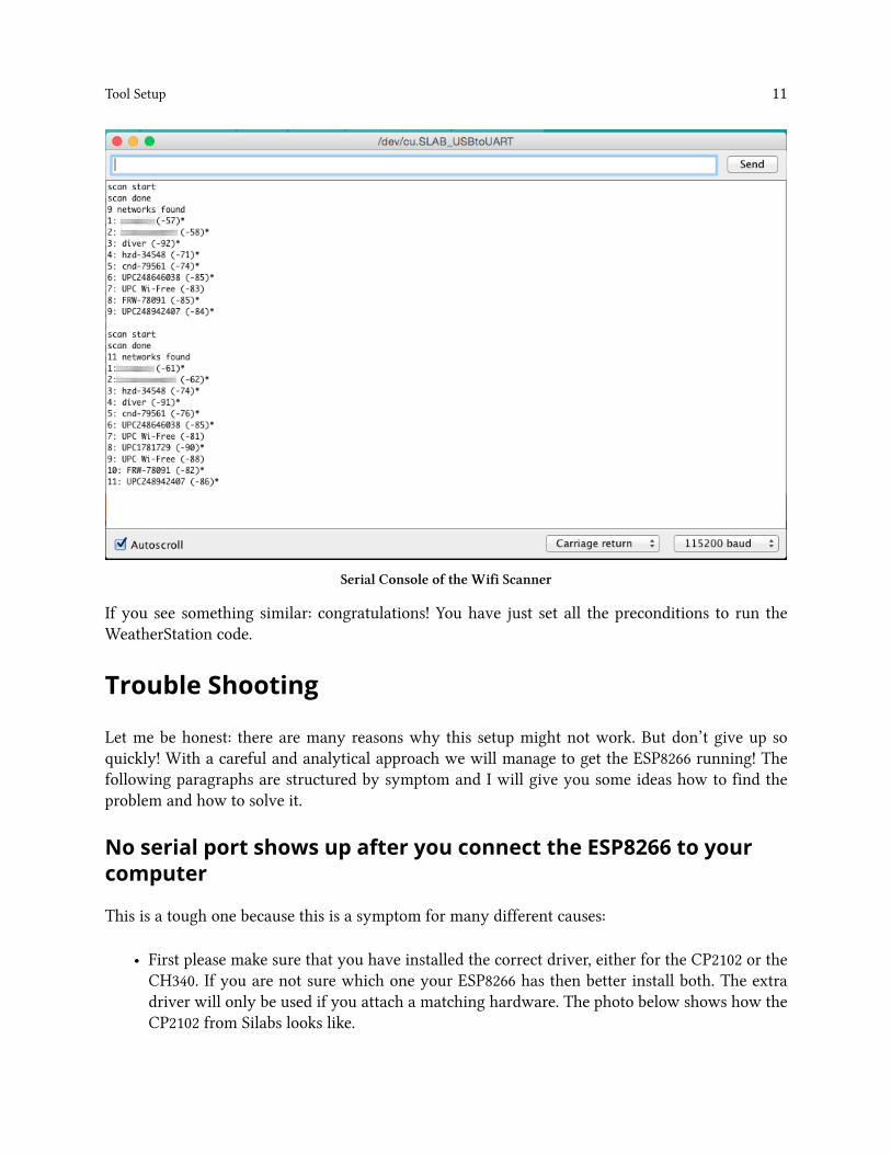
If you see Done uploading. in the window, then click on the magnifying glass on the top right ofthe window. This is the serial console that you can use to see output from the NodeMCU module,or to send commands to the device. Make sure that the baud rate is set to 115200. This rate is alsoset in the example code, and if you have a different setting the ESP will talk with a different speedthan your PC listens. You can set the baud rate on the bottom left of the serial monitor. My outputlooks like this:
Tool Setup 11
Serial Console of the Wifi Scanner
If you see something similar: congratulations! You have just set all the preconditions to run theWeatherStation code.
Trouble Shooting
Let me be honest: there are many reasons why this setup might not work. But don’t give up soquickly! With a careful and analytical approach we will manage to get the ESP8266 running! Thefollowing paragraphs are structured by symptom and I will give you some ideas how to find theproblem and how to solve it.
No serial port shows up after you connect the ESP8266 to yourcomputer
This is a tough one because this is a symptom for many different causes:
• First please make sure that you have installed the correct driver, either for the CP2102 or theCH340. If you are not sure which one your ESP8266 has then better install both. The extradriver will only be used if you attach a matching hardware. The photo below shows how theCP2102 from Silabs looks like.

Tool Setup 12
NodeMCU with a Silabs CP2102
• Another possible and frequent culprit is the USB cable. If you are sure that you installed theright drivers then try to use a different USB cable with the ESP8266. As a cross check you canalso use the USB cable with another device (e.g. smartphone) and connect it to your PC. Ifthe device is not recognized by your computer (and it is one that should be recognized) thenthrow the faulty cable away
• Sometimes it helps to restart your computer or choose another USB port. It happened to meseveral times that one USB port stopped working and only after a restart or changing the portthe device would show up.
• It also happens relatively often that the NodeMCU is dead. But it is relatively hard to be100% sure that it is really not working. If you previously didn’t identify driver or cable asthe cause for the problem we should focus on the NodeMCU module. Let’s have a close lookat the device. There are two LEDs: one on the ESP8266 module close to the antenna and theother one closer to the buttons. Do you see anything blink when you plug in the USB cableand connect it to your PC? If it blinks then the ESP8266 could be OK but the Serial-to-USBconverter could be damaged. If there is no light then there are still many possibilities.
Failure during upload like espcomm_upload_mem failed
When you try to upload you see something like this in the console:

Tool Setup 13
1 warning: espcomm_sync failed
2 error: espcomm_open failed
3 error: espcomm_upload_mem failed
4 error: espcomm_upload_mem failed
This means that for a number of reasons your computer could not upload the firmware to theNodeMCU. To understand what might be the cause we need to see what is happening during theupload of a new binary. Before the availability of easy-to-use developer modules like the NodeMCUyou had to manually connect some pins of the ESP8266 to boot it into flash mode after a reset. Thiswas very annoying since for every change in the code you had to compile, connect the pins, resetthe ESP, wait until upload was complete, disconnect the boot mode pins and do a reset. Moduleslike the NodeMCU make this a lot easier since they have a special circuit which does all that whenthe serial-to-usb converter detects a special signal from your computer. Wonderful, right? Except: itdoesn’t always work. First let’s try if the serial connection is working at all. Connect the NodeMCUto your computer and open the serial console. Now press the RST button and check what will beprinted in the console. Depending on the selected transfer speed (lower right corner of the serialmonitor) you either see strange characters or something similar to this:
1 ets Jan 8 2013,rst cause:2, boot mode:(3,6)
2
3 load 0x4010f000, len 1384, room 16
4 tail 8
5 chksum 0x2d
6 csum 0x2d
7 v3ffe85e8
8 ~ld
I had to set the speed to 74880 baud to get this output. If you see this text then your computer andyour ESP8266 can communicate with each other. Now we try to fix it by one of these measures:
• Press and hold the button labelled FLASH while pressing the button labelled RST. Then tryagain if the upload works. This button combination will manually set the ESP8266 into flashmode
• The settings in the Arduino Tool menu are also a frequent source of problems: have youselected the right board (e.g. NodeMCU V1.0) and the right USB/Serial port? Try also differentupload speeds. The NodeMCU should automatically detect the requested transfer speed butthis does not always work.
Summary
Before we continue to the WeatherStation project let’s have a closer look at what we justaccomplished:

Tool Setup 14
1. We installed a driver which lets us program the ESP8266 with custom code that we wrote.Which driver needs to be installed depends on the Serial-to-USB converter we use. Some ESPmodules already have such a converter; others will need an additional one.
2. We downloaded and installed the Arduino IDE. In the IDE we write the code, compile it andtransfer it to the embedded device. If our code supports it we can even use the Serial Monitorto communicate with the device.
3. We used an example project, called a Sketch, to test our setup. The sample project installsfirmware which uses the WiFi module to scan for available WiFi access points. It repeatedlywrites this data to the serial line, and we can display it by opening the Serial Monitor tool.Remember, in a serial communication both parties need to agree on the speed the charactersare getting transmitted. The example sets this to 115200 baud.

ESP8266 Programming BasicsIn this chapter we will have a look at the building blocks of an Arduino sketch. This will help youto understand and modify the WeatherStation which we will build in the next chapter. If you justwant to get the WeatherStation running you can skip this chapter.
Preparation
In this chapter we will work with exercises which you can download from GitHub. They containseveral Arduino projects for the ESP8266. For an exercise open the related project in your ArduinoIDE and try to solve the given task. If you get stuck or want to see an alternative solution open theproject which ends with “_Solution”:
• Exercise_04_01: contains the first exercise in chapter 4• Exercise_04_01_Solution: contains a possible solution
Now download the Zip file from GitHub and extract it in a place you will find it later. There is agreen “Clone or download” button which lets you download a Zip file:
https://github.com/squix78/esp8266-getting-started
The Arduino Sketch
The Arduino platform was built with the beginner in mind. Compared to a normal C programthe Arduino IDE hides a few things from you to simplify the setup. First of all you do not haveto create a makefile to build your code into an executable binary. The Arduino IDE also includes adefault header file for you: #include "Arduino.h". This contains all definitions needed for a regularArduino program.
Another important change compared to a regular C/C++ program are the two default functionssetup() and loop(). The first will be only called once during startup, while the loop()method willbe called repeatedly. On a normal Arduino hardware (ATmega chip) you can theoretically write codeand never leave the loop()method again. The ESP8266 is a bit different here. If your operations runfor too much time a so-called watchdog will reset the ESP8266. You can prevent this by allowingthe controller to do important operations while you are still in the main loop. Calling yield() ordelay(ms) will do this.

ESP8266 Programming Basics 16
Hello World: The serial console
Every self-respecting programming tutorial starts with a “Hello World” program. And I don’t wantto break with this tradition here. A Hello-World program usually does no more than printing thesetwo words somewhere on the screen. But we are programming a microcontroller which does nothave a screen yet. So where can we display the text? We will use the Serial object to do that. Whileyou are developing a program on the ESP8266, the microcontroller is connected to the computerthat the Arduino IDE is running on. We use this connection to write a new binary onto the flashmemory of the ESP8266. And while our program is running we can also use it to write messagesfrom the ESP8266 back to our computer.
Using the Serial object is fairly easy. You have to initialize it first:
1 Serial.begin(115200);
This tells the Serial object that you want to communicate with a baud rate of 115200. Rememberto set the same transfer rate later in the serial console on your computer. Both partners in thecommunication need to have the same speed settings or you will just see garbage. If you wantto send a message from your program to your computer you just do this:
1 Serial.print("Hello ");
2 Serial.println("World");
Please have a look at the little difference between the first and the second line. The first uses amethod called print() and the second println(). The only difference is that the latter adds a linebreak to the output.

ESP8266 Programming Basics 17
Exercise 04.01: Hello world!Now it is time to write our first program. Open the project Exercise_04_01 in yourArduino IDE and fill in the required code to print “1. Hello World”, “2. Hello World”etc. Remember that you only need to initialize the Serial object once, while you’llhave to print “<number>. Hello world” as long as the code runs.
Once you are happy with your solution upload the sketch to your Arduino byclicking
If that was successful open the serial console by clicking on the magnifying glass:
Now your output should look something like this:
If you want to learn more about the Serial object you can find more in the following link:
http://esp8266.github.io/Arduino/versions/2.3.0/doc/reference.html#serial
The exercise contains another important built-in function:
1 delay(1000);
This instructs the processor to wait 1000 milliseconds (1 second) before continuing with theexecution. As mentioned earlier with this command it also gives the processor time to handle other

ESP8266 Programming Basics 18
tasks, such as receiving or sending network packets over WiFi. In this context a call to yield() doesthe same as delay(0).
Input/Output: GPIO pins
Now that we can talk to our microcontroller over the serial line it is time to interact with the realworld. Our ESP8266 is equipped with several so-called General Purpose Input Output or in shortGPIO pins. They can be used for many different applications such as sensing and generating digitalsignals of the 3.3 Volt range. This is important if you plan to use an external component with yourESP8266: hardware designed for older Arduinos often uses the 5V (CMOS) range. Using such a devicewithout a logic level shifter might destroy your ESP8266.
Using a GPIO pin is quite easy: first you tell the microcontroller if you want to read or write fromthe pin. Then you do it. Here is the code for reading:
1 pinMode(PIN, INPUT);
2 int state = digitalRead(PIN);
Unless you want to change the mode of a pin you only need to call pinMode() once. Please note thatdepending on the pin you can also use INPUT_PULLUP or INPUT_PULLDOWN. Writing to a pin is notmuch different:
1 pinMode(PIN, OUTPUT);
2 digitalWrite(PIN, HIGH); // or
3 digitalWrite(PIN, LOW);
The second statement will show a HIGH level on PIN which will be 3.3V. The third statement will setthe pin to LOW which is 0V.
What values for PIN can you use? If you are using a generic ESP8266 module (not a NodeMCU) yourpins will be labeled GPIO0, GPIO1, etc. To use pin GPIO0 you would write digitalWrite(0, HIGH);
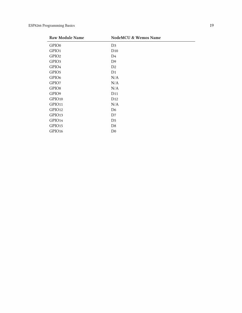
If you are using a NodeMCU things get a little bit more complicated. The original creators of theNodeMCU LUA firmware and the development module of the same name had the idea to give thepins different names. They are called D0, D1, etc. That by itself would not be confusing yet but theyare not using the same digits, e.g. GPIO1 is not equal to D1. Here is a table to map the pins:
ESP8266 Programming Basics 19
Raw Module Name NodeMCU &Wemos Name
GPIO0 D3GPIO1 D10GPIO2 D4GPIO3 D9GPIO4 D2GPIO5 D1GPIO6 N/AGPIO7 N/AGPIO8 N/AGPIO9 D11GPIO10 D12GPIO11 N/AGPIO12 D6GPIO13 D7GPIO14 D5GPIO15 D8GPIO16 D0

ESP8266 Programming Basics 20
NodeMCU DevKit Pin Map https://github.com/nodemcu/nodemcu-devkit-v1.0
Exercise 04.02: Can’t touch this!?In this exercise you are going to read from the button on your NodeMCU labelled withFLASH. This button is connected to the D3 pin. Put the D3 pin to input mode in the setup()method and read from the pin repeatedly in the loop() and write the results to the console.
Exercise 04.03: Led it shine!Let’s control an LED! Your NodeMCU has one built in and it is connected to D0. Like in theprevious example set the pin to the correct mode and then toggle it once per second.

ESP8266 Programming Basics 21
Exercise 04.04: Every breath you take! (Bonusfor Experts)Pure blinking is boring. We want our little ESP8266 to live! Control the intensity of the LEDand make it look as if the ESP8266 was breathing. Note: if the LED was on another pin thanD0 we would use pulse width modulation (PWM) and the writeAnalog(PIN, INTENSITY)
method. But this feature is not available on D0 so you will have to do this in your code.
Interrupts
Depending on your age you might remember interrupts from your PC. They were always importantto get your sound card to play beautiful music. The ESP8266 can also be controlled by interrupts. Inthe previous exercises we were checking regularly for the state of a GPIO pin. This is fine if you arenot doing anything else in the main loop. But you might miss a change in a state if it is very short,and that is were the interrupts can help. With an interrupt handler you can tell the processor thatyou are interested in a specific type of change and a given pin. This is how it works:
1 void buttonPressed() {
2 ...
3 }
4
5 void setup() {
6 pinMode(PIN, INPUT);
7 attachInterrupt(digitalPinToInterrupt(PIN), buttonPressed, CHANGE);
8 }
buttonPressed() is a method without parameters that gets called when there is a change on PIN.Instead of CHANGE you can also use RISING which triggers the callback when the pin changes fromLOW to HIGH, or FALLING for a change in the opposite direction. Please do not execute long tasks inthe callback method. The ESP’s watchdog will reset the processor if calling the interrupt takes toomuch time. You should not do much more than changing a flag.
Exercise 04.05: I don’t want to miss a thing!In this exercise we will setup an interrupt and turn an LED on and off with every press tothe button. See what happens when you use different interrupt modes like RISING, FALLINGand CHANGE.

ESP8266 Programming Basics 22
Measuring analog signals
So far we can read and write the digital states HIGHand LOW, but what if we want to deal with analogsignals? The ESP has one Analog To Digital Converter (ADC) which can be used to measure voltagein the range 0 - 1V. To do that use the following command:
1 unsigned value = analogRead(A0);
You can also use the ADC to measure the input voltage without any additional wiring. You have toinstruct the processor that you want to measure the supply voltage rather than the value on A0 witha special command outside the setup() and loop() method. Here is an example:
1 ADC_MODE(ADC_VCC);
2
3 void setup() {
4 Serial.begin(115200);
5 }
6
7 void loop() {
8 Serial.println(ESP.getVcc());
9 delay(500);
10 }
WiFi
The last few chapters were all about built-in functions of the Arduino/ESP8266 platform. Now wewill start using libraries which are part of the platform and are already installed. So how can we usethe WiFi module of the ESP8266? First of all you need to know that the ESP8266 can operate as aWiFi client (like a smartphone or laptop) and/or as an access point (like a WiFi router or extender).You can set this mode with:
1 WiFi.mode(m);
where mmust be one of the following modes: WIFI_AP (access point), WIFI_STA (client), WIFI_AP_STA(AP and client) or WIFI_OFF.
Now let’s connect to your access point:
1 WiFi.begin(WIFI_SSID, WIFI_PWD);
This will connect you to an access point given its SSID and the password. Please note that this callis not blocking. This means that the code will immediately proceed to the next instruction whetherthe ESP successfully connects to the access point or not.
ESP8266 Programming Basics 23
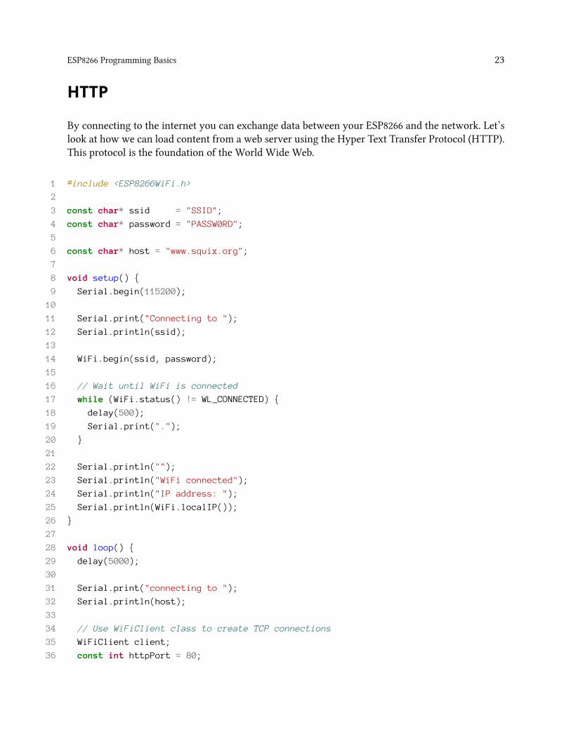
HTTP
By connecting to the internet you can exchange data between your ESP8266 and the network. Let’slook at how we can load content from a web server using the Hyper Text Transfer Protocol (HTTP).This protocol is the foundation of the World Wide Web.
1 #include <ESP8266WiFi.h>
2
3 const char* ssid = "SSID";
4 const char* password = "PASSW0RD";
5
6 const char* host = "www.squix.org";
7
8 void setup() {
9 Serial.begin(115200);
10
11 Serial.print("Connecting to ");
12 Serial.println(ssid);
13
14 WiFi.begin(ssid, password);
15
16 // Wait until WiFi is connected
17 while (WiFi.status() != WL_CONNECTED) {
18 delay(500);
19 Serial.print(".");
20 }
21
22 Serial.println("");
23 Serial.println("WiFi connected");
24 Serial.println("IP address: ");
25 Serial.println(WiFi.localIP());
26 }
27
28 void loop() {
29 delay(5000);
30
31 Serial.print("connecting to ");
32 Serial.println(host);
33
34 // Use WiFiClient class to create TCP connections
35 WiFiClient client;
36 const int httpPort = 80;

ESP8266 Programming Basics 24
37 if (!client.connect(host, httpPort)) {
38 Serial.println("connection failed");
39 return;
40 }
41
42 // We now create a URI for the request
43 String url = "/guide/";
44
45 Serial.print("Requesting URL: ");
46 Serial.println(url);
47
48 // This will send the request to the server
49 client.print(String("GET ") + url + " HTTP/1.1\r\n" +
50 "Host: " + host + "\r\n" +
51 "Connection: close\r\n\r\n");
52
53 unsigned long timeout = millis();
54 while (client.available() == 0) {
55 if (millis() - timeout > 5000) {
56 Serial.println(">>> Client Timeout !");
57 client.stop();
58 return;
59 }
60 }
61
62 // Read all the lines of the reply from server and print them to Serial
63 while(client.available()){
64 String line = client.readStringUntil('\r');
65 Serial.print(line);
66 }
67
68 }
How does this work? First we define the SSID and password of the WiFi access point we want toconnect to. Please note that there are better ways to do that. The WiFiManager (https://github.com/tzapu/WiFiManager) for instance starts the ESP8266 as an access point if it cannot connect to anySSID. You then use your smartphone to configure the WiFi credentials and there is no need to hardcode these into your firmware. But for the sake of simplicity let’s ignore this here.
On line 14 we start connecting to the defined access point and wait until the connection isestablished. After all there is no point to send requests to a server if the network connection isnot confirmed yet.
Line 49 sends the request to the server. The command GET /guide/ HTTP/1.1\r\n might look

ESP8266 Programming Basics 25
strange to you. This is how your browser talks to the web server. GET is the command for thewebserver, /guide/ is the resource on the server we want to get and HTTP/1.1 is the protocol thatwe are using. If you are interested how this works in detail have a look at this Wikipedia article:https://en.wikipedia.org/wiki/Hypertext_Transfer_Protocol.
On line 63 we print out the response line by line as long as there is text coming in.
Sadly this is quite complicated. Especially if we want to add encryption in the form of SSL to theconnection. This protects your data and makes sure that you are talking to the right server. With thefollowing command we can verify that the host matches the given SHA1 fingerprint.
1 if (client.verify(fingerprint, host)) {
2 Serial.println("certificate matches");
3 } else {
4 Serial.println("certificate doesn't match");
5 return;
6 }
How can you find this fingerprint? Your browser can help you with this. I will show it with Chrome.First open the page you need the fingerprint for, in my case www.google.ch. Then click on the littlelock symbol and then on Details:
A click on View Certificate will bring up the detail window about Google’s certificate:

ESP8266 Programming Basics 26
Scroll down to the bottom of the window and copy the value behind SHA1. This is the fingerprint toverify that you are actually talking to www.google.ch.
Exercise 04.06: Better safe than sorry!In this exercise we will start with the same program as I included earlier in this chapter.But now you are going to change the code to receive the search site from google on a securechannel. Complete the following tasks:
1. Change the host from www.squix.org to www.google.ch
2. Get the SHA1 fingerprint for www.google.ch3. Add a check that this fingerprint matches www.google.ch

The ESP8266 WeatherStationIn this chapter we will get theWeatherStation to run. We will install several libraries used for settingup access to the internet, for reading and parsing the data from the service providing your localweather forecasts, as well as a library to display the data on the OLED display. Then we will adjustthe WeatherStation code to display your local weather information and get a so-called API key toaccess the weather forecast service.
Installing the libraries
Libraries: If you are new to programming you might ask what libraries are. When wedevelop programs we use libraries to not have to invent the wheel over and over again.Libraries contain functionality that might be used in different places without creatingcopies of code which is hard to maintain. So for you libraries are a wonderful thing: youcan concentrate on the things that really matter to you. In the case of the WeatherStationthey provide a lot of functionality which normally would take you a lot of time to writeyourself.
In order to get the WeatherStation to compile you will have to download three libraries. The firstlibrary is the WeatherStation itself. This will give you some new entries in the Example menu of theArduino IDE. The second one is to read and understand the data which the program gets from theweather forecast service. And the third is needed to use the beautiful OLED display.
Go to Sketch > Include Library… > Manage Libraries… and install the following three libraries.Make sure that you always have the latest version of the libraries installed. Users have reportedmany issues which could be reduced by simply updating the library. Also make sure that you onlyhave one version of each of the libraries installed.
ESP8266 Weather Station Library

The ESP8266 WeatherStation 28
SSD1306 OLED Library
Json Streaming Parser Library
Open the Weather Station Example
You have now installed the three required libraries. OftenArduino libraries contain example sketcheswhich behave like a template to kick-start your project. If you have alreadyworked with the ArduinoIDE you might have used other demo sketches before. In the last chapter we used the Wifi ScannerSketch. Nowwe are going to use theWeatherStation template to get started. Go to File > Examples
> ESP8266 Weather Station > WeatherStationDemo Save the new sketch with a good name in alocation you will remember - but leave it open.
Getting the Wunderground API Key
API (Key): What is an API and what is an API Key? Application Programming Interfaces(APIs) are a well-defined way on how one piece of code can talk to another. This can be onthe same device, but often refers to the communication between two devices connectedby a network. For the WeatherStation we need to get current and forecast data in amachine-readable format. To do this we will call the API of a service calledWunderground.Wunderground has different price plans and we will use the Free plan which has somelimitations to distinguish it from the per-pay plan. To have better control over the userswho access the service we will have to get a short text value - the API key - before we cancall it. You should treat API keys like a password and be careful with them. For instance,do not post them to a forum, and don’t commit them to a public code repository. If you doyour key may be cancelled, and all your projects will fail!

The ESP8266 WeatherStation 29
To get the Wunderground API key go to https://www.wunderground.com/weather/api/d/pricing.html and pick the “Stratus Developer” plan. Then get your API key from this page:
Wunderground API Page
If you should forget your key you can always come back and get it here.
Configuring the Weather Station
Earlier when you chose the WeatherStation example you created a copy of the code included in thelibrary. This code needs to be adapted so that it works for you. There are better options than puttingconfiguration into your code: we could for instance offer a web interface where you could configureyour settings. This would be much better since you could change values without changing the code,which would require compiling a new firmware and sending it over to the device. But to get startedwe will try to keep things simple…
• Let’s start with theWiFi Settings. Replace yourssid with the name of your WiFi network andyourpassw0rd with its password. I had problems with a network that contained a dash (“-“)in the SSID. If you are having problems consider this hint…
• Next is theupdate interval. This value specifies how often theweather data should be updatedfrom the internet. The default is 600 seconds (10 minutes). In my experience this is a goodvalue, because you don’t have unlimited requests in your free Wunderground API accountand the weather doesn’t change so often anyway.
• Now to theDisplay Settings. If you attach the display as I show in the next chapter you don’thave to change anything here. D3 and D4 are the pin names in the NodeMCU module. If youget compilation errors about them make sure that you have set your board to NodeMCU V1.0,if that is the module you are using. If you have another board just replace the pin numberswith the proper pin number, e.g. 5 or 6.
• Use the Time Client Settings section to adjust your local time zone offset compared to theUTC time zone. It also allows a half-hour offset, thanks to the user who lives in such a timezone and made me implement that. (Ignorance is bliss until you get confronted with it…)

The ESP8266 WeatherStation 30
• In the Wunderground section you can now use the API key you received in the previoussection. Also set the country and city of the place you want to show. To figure out which val-ues work you can modify this URL: http://api.wunderground.com/api/3APIKEY/conditions/q/CA/San_Francisco.json and replace APIKEYwith yours and CA and San_Franciscowith yourstate or country and city.
For the moment ignore the ThingSpeak settings. You might use it in a future project (have a look atthe “More Projects” chapter). Now we are almost ready to get the weather station running on theESP8266 for the first time. But we need to wire the display to the NodeMCU first.
Connecting the Hardware
The WeatherStation Kit comes with an OLED display that has four connectors: VCC, GND, SCL andSDA. They have the following meaning:
• VCC and GND are the power supply of the display. VCC is the positive supply voltage and GND
stands for “ground”. They will be connected to 3V3 and GND on the NodeMCU board• SCL and SDA are the data lines of the I2C protocol. SCL stands for Serial Clock and SDA forSerial Data.
In the following diagram I used a breadboard and male-to-male jumpers to connect the components.But you can also connect them directly with four (colored) female-to-female jumpers. They comewith the WeatherStation Kit. Just peel the first four wires off of the bundle and connect themaccording to the picture. The colors do not matter.

The ESP8266 WeatherStation 31
Wiring the Weather Station
Please note: there are versions of the OLED display with swapped GND and VCC pins. Be careful toconnect them according to the printed labels, not (necessarily) this diagram!
NodeMCU Pin OLED Display Pin
3V3 VCCGND GNDD3 SDAD4 SCL
As mentioned earlier, there exists a little confusion about the pin names. The Arduino IDE usesthe GPIO number given by the chip. The NodeMCU team who designed the board changed thepin naming for their LUA firmware. If you are programming a NodeMCU module you can use theprinted D# names. If you use a generic ESP8266 module then you have to use the correspondingGPIO numbers. Here is a table of the mapping:

The ESP8266 WeatherStation 32
NodeMCU Index ESP8266 Internal NodeMCU Index ESP8266 Internal
D0 GPIO16 D7 GPIO13D1 GPIO5 D8 GPIO5D2 GPIO4 D9 GPIO3D3 GPIO0 D10 GPIO1D4 GPIO2 D11 GPIO9D5 GPIO14 D12 GPIO10D6 GPIO12
The NodeMCU Index is the name on the board, whereas the ESP8266 Internal column is the one youuse in the Arduino IDE code: e.g. D5 on the board is pin GPIO14 in C/C++.
First Run
Now we’re all set to run the WeatherStation software for the first time. Click on the Upload arrowand wait until the compilation and the transfer have ended. Now you should see the OLED displaylighting up and displaying a WiFi icon. The module should now be trying to acquire access to thewireless network you have defined earlier.
This is just the beginning. In the next chapter I’ll give you some ideas of what else you can buildwith the WeatherStation hardware.
Summary
If everything went well you now have a working ESP8266 WeatherStation. Congratulations! Let’slook back what we did in this chapter:
1. We used the WeatherStation example and created a working copy for us. All changes will beapplied to the copy, not the original example. If you accidentally make your code unusableyou can always go back to the example and start with a fresh copy.
2. We installed several libraries by using the Arduino IDE Library Manager. Libraries help us toreuse code or binaries in many places without using barely maintainable copy/paste code.
3. We created an API key from Wunderground. Every time we call the Wunderground API toupdate weather data we will send this key along so that Wunderground knows who we are.Many service providers use a similar scheme to control and limit usage of their services.
4. We changed a few lines in the code to configure the WiFi settings, update interval, displaypins, timezone and the API key for Wunderground.
5. We connected the OLED display and the ESP8266 and uploaded the firmware.

The WeatherStation Code ExplainedIn this chapter we will have a look at the building blocks of the WeatherStation. This project is arelatively complex piece of code and I hope to improve this chapter over time with new details.Please consider subscribing at https://blog.squix.org/subscribe to get notified about updates.
The JSON Streaming Parser
You might not know it but the most important puzzle piece for the WeatherStation project is a thingcalled a streaming parser. What is a streaming parser? You are most certainly using parsers everyday. A parser is a piece of code that analyses an input (text, document) by reading in its content.To do that the parser has knowledge about the structure of the text, sometimes called a syntax. Thesyntax is like the grammar of your natural language. A web browser you are using to read newsuses an HTML parser to understand the tags that are downloaded from the webserver and then putinto a visualization with formatted text, pictures and links.
So now that we roughly understand what a parser is the next question would be what is a streamingparser? With a modern smartphone or desktop computer we often don’t need streaming parsersanymore, we use document object model parsers (DOM) parsers instead. A DOM parser creates atree-like structure of the document it parses, keeps this structure in memory and makes it availablefor the code that does something meaningful with it. DOM parsers are very easy to use, fast andconvenient. But this convenience comes at the price of memory requirements. The DOM parserneeds a lot of memory, since it keeps the whole document in memory until it is no longer used. Ifyou have a lot of RAM and your documents are not that big this is perfectly fine. But if the documentsare big compared to the available (heap) memory you might run into a serious problem.
Imagine the parser to be something like a water meter andwe are comparing now two different typesof meters. A water meter which works like a DOM parser needs a bucket and measures the amountof water by filling the bucket and then measuring the weight of the water in the bucket. If thereis a lot of water then the bucket must be big. A water meter which works like a streaming parsermeasures the water while it flows through and doesn’t care what happens to the water afterwards.The bucket in this analogy is the heap or working memory of your microcontroller, the water is thestream of bits and bytes that you receive, either from the file system or from a remote server. And theparser does not just measure the amount of bits and bytes but also tries to understand the content.The streaming parser doesn’t care how big the document (or the amount of water) is, it just takes outwhat it needs from the stream. Streaming parsers are also referred to as event-based parsers sincethey react to certain events in the data stream. DOM parsers are referred to as tree-based parserssince they build a full representation of the document in the tree-like structure. In an HTML treethe html element would be the root of the tree, and the body tag a fork in that tree.

The WeatherStation Code Explained 34
The Grammar
The following image describes the grammar of a valid JSON object in a very concise way. It meansthat a JSON object knows three basic types:
• object• array and• value
JSON grammar
Objects always start and end with curly brackets. They can be either empty (line to the top) orcontain string/value pairs, separated by a colon. These pairs can be repeated by adding a comma

The WeatherStation Code Explained 35
between them. Arrays start and end with square brackets. They can be either empty or contain avalue. At this point we don’t know yet what a value is. Values in an array can be repeated and mustbe separated by a comma. Values were already used for the two previous definitions and here liesthe power of this kind of grammar: because a value can contain a simple text, a number, an object(yes, the object we defined before!!!), an array (also defined before), booleans or a null value.
This is so powerful because we are reusing the definitions and we are nesting them within eachother: an object can contain a value, a value can contain an array or an object. And finally an arraycan contain a value, repeatedly! Isn’t this beautiful?
The JSON Streaming Parser Library
Why would we want to use a streaming parser on the ESP8266? Embedded devices usually havevery limited resources available. One scarce resource is the heap memory. Many of the REST APIsI am using in my projects provide big response objects, but we are usually just interested in a smallfraction of it. As mentioned earlier, a tree-based parser would load the whole document intomemoryand make it available once the document stream has ended. And this would just crash the ESP8266pretty quickly; it does not have the resources to keep 200kb on the heap.
This made me port a PHP JSON parser over to C++ and make it available as a library, mostly to beused in my own projects. Let’s have a look at the header file of the JsonListener:
1 class JsonListener {
2 public:
3 virtual void whitespace(char c) = 0;
4 virtual void startDocument() = 0;
5 virtual void key(String key) = 0;
6 virtual void value(String value) = 0;
7 virtual void endArray() = 0;
8 virtual void endObject() = 0;
9 virtual void endDocument() = 0;
10 virtual void startArray() = 0;
11 virtual void startObject() = 0;
12 };
The methods here are callback methods which will get invoked if the respective event happens whileparsing the document. Let’s start with an example. For the JSON object {“name”: “Eichhorn”} weget the following invocations:
• startDocument(): we start receiving a json document• startObject(): the json object starts with “{“• key(“name”): the parser detected a key object which contains “name”
The WeatherStation Code Explained 36
• value(“Eichhorn”): the parser detected a value containing “Eichhorn”• endObject(): the object ends with “}”• endDocument(): the stream of data ends and so does the document
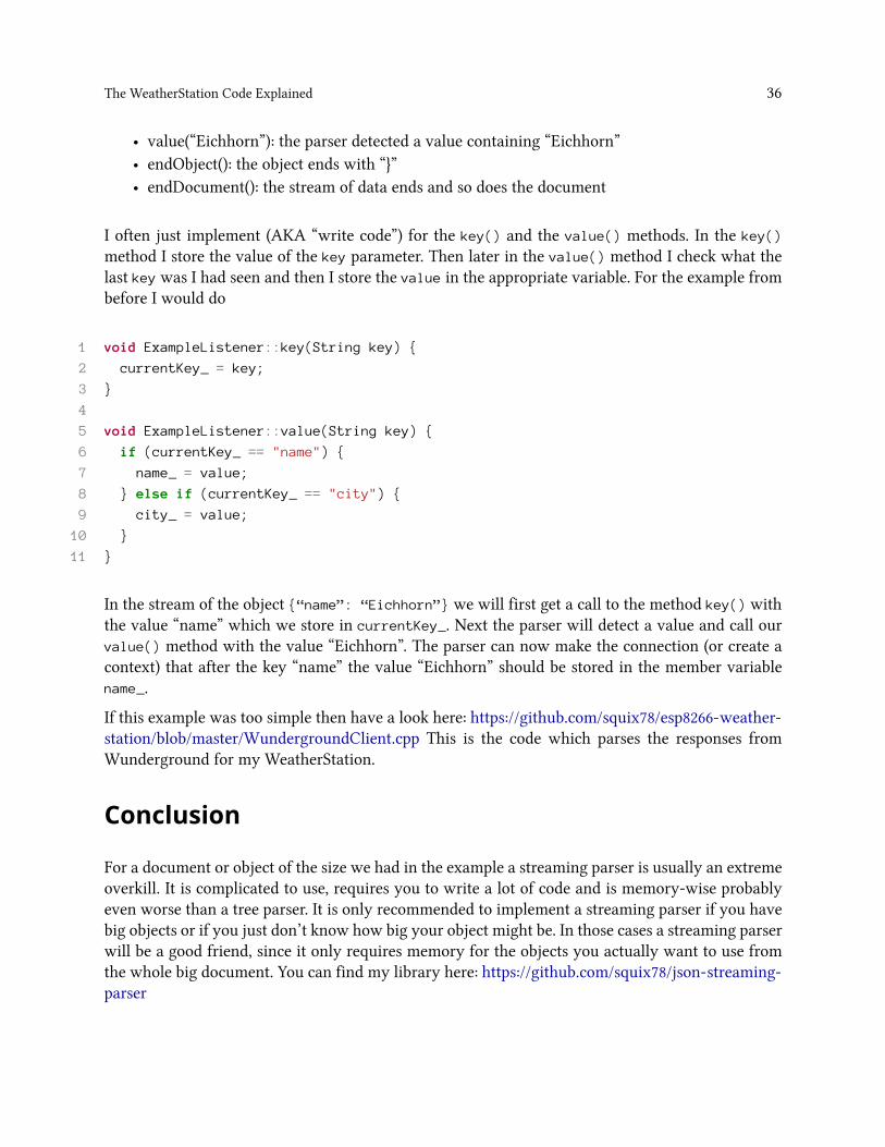
I often just implement (AKA “write code”) for the key() and the value() methods. In the key()
method I store the value of the key parameter. Then later in the value() method I check what thelast key was I had seen and then I store the value in the appropriate variable. For the example frombefore I would do
1 void ExampleListener::key(String key) {
2 currentKey_ = key;
3 }
4
5 void ExampleListener::value(String key) {
6 if (currentKey_ == "name") {
7 name_ = value;
8 } else if (currentKey_ == "city") {
9 city_ = value;
10 }
11 }
In the stream of the object {“name”: “Eichhorn”} we will first get a call to the method key() withthe value “name” which we store in currentKey_. Next the parser will detect a value and call ourvalue() method with the value “Eichhorn”. The parser can now make the connection (or create acontext) that after the key “name” the value “Eichhorn” should be stored in the member variablename_.
If this example was too simple then have a look here: https://github.com/squix78/esp8266-weather-station/blob/master/WundergroundClient.cpp This is the code which parses the responses fromWunderground for my WeatherStation.
Conclusion
For a document or object of the size we had in the example a streaming parser is usually an extremeoverkill. It is complicated to use, requires you to write a lot of code and is memory-wise probablyeven worse than a tree parser. It is only recommended to implement a streaming parser if you havebig objects or if you just don’t know how big your object might be. In those cases a streaming parserwill be a good friend, since it only requires memory for the objects you actually want to use fromthe whole big document. You can find my library here: https://github.com/squix78/json-streaming-parser

Collecting and Displaying Local DataSo far we have created a device which connects to the internet and uses an API to fetch weatherdata. But this is not really an Internet-of-Things application; after all we are just displaying data. Inthis chapter we will change that.
The Climate Node Setup
This project will enable you to collect humidity and temperature in one room of your house orapartment and display the values in another room on the WeatherStation. In order to do so you willneed additional hardware which is not included in the basic WeatherStation Starter Kit:
• An additional ESP8266 module, ideally a NodeMCU• a DHT11 or DHT22 humidity and temperature breakout module
I will call this combo “The Climate Node”. Now use the female-to-female jumpers to connect themlike this:
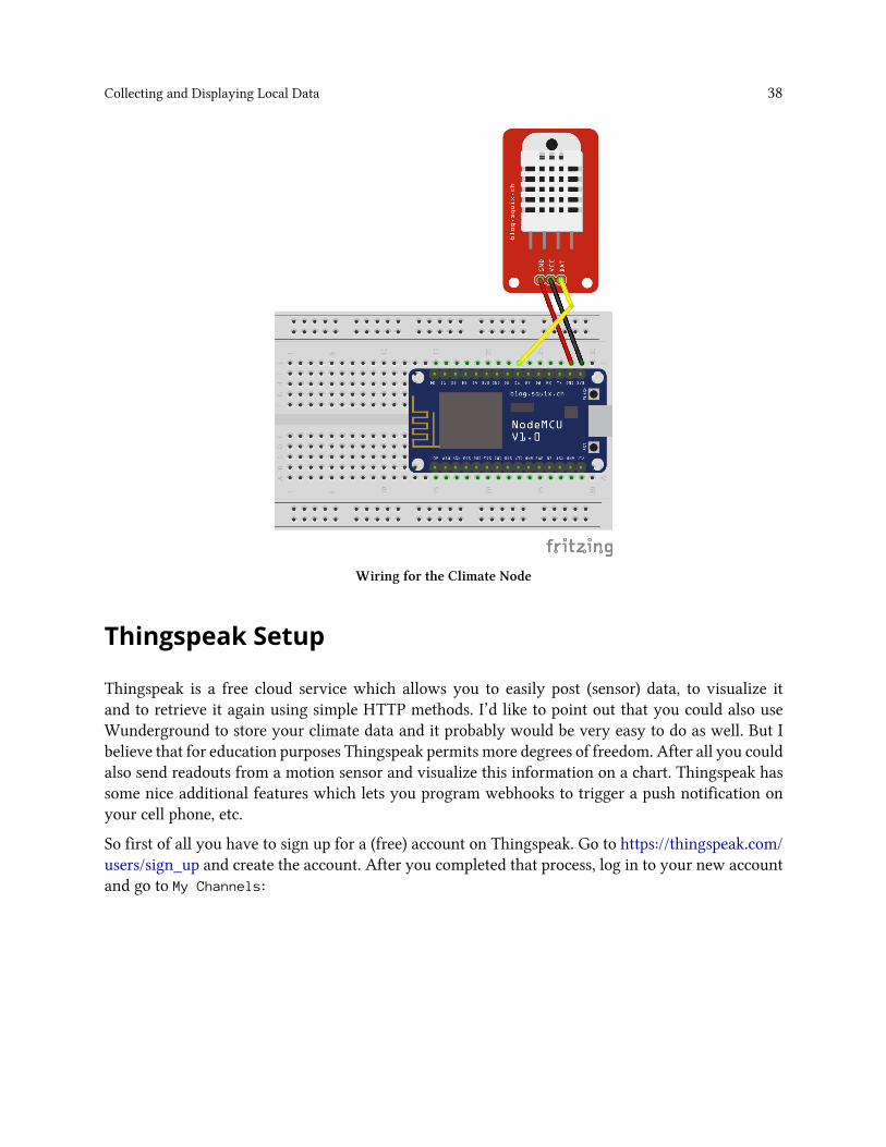
Collecting and Displaying Local Data 38
Wiring for the Climate Node
Thingspeak Setup
Thingspeak is a free cloud service which allows you to easily post (sensor) data, to visualize itand to retrieve it again using simple HTTP methods. I’d like to point out that you could also useWunderground to store your climate data and it probably would be very easy to do as well. But Ibelieve that for education purposes Thingspeak permits more degrees of freedom. After all you couldalso send readouts from a motion sensor and visualize this information on a chart. Thingspeak hassome nice additional features which lets you program webhooks to trigger a push notification onyour cell phone, etc.
So first of all you have to sign up for a (free) account on Thingspeak. Go to https://thingspeak.com/users/sign_up and create the account. After you completed that process, log in to your new accountand go to My Channels:

Collecting and Displaying Local Data 39
Navigate to My Channel
Then you click on the New Channel button, and fill out the form:
Fill out the New Channel Form
Explanation: The name just helps you to recognize your channel among many others that you mightcreate over time. The important parts are the field names. These names will later show up in thechart and with this you are telling Thingspeak that the value you send later with the field1 attributeshould be displayed as “Temperature”.
Now navigate to the API Keys tab and note the two generated keys:

Collecting and Displaying Local Data 40
Thingspeak API keys
The first one will allow you to write to this channel in Thingspeak, and the second one will allowyou to read from it. Treat them as secrets and with care. Others might be able to spam your channelor to “steal” your data. We will use these keys soon enough… Also note the channel ID on top of thescreen, in my case 76642.

Collecting and Displaying Local Data 41
Programming the Climate Node
Now we have all the ingredients to post the climate data to Thingspeak. We just have to programthe ESP8266 accordingly. Go to https://github.com/squix78/esp8266-dht-thingspeak-logger anddownload the code as a Zip file (or optionally do a GitHub checkout).
Now adapt the settings to your needs: In particular the Wifi settings and the Thingspeak API keyhave to be updated. Take the Write API key from the previous step. For testing you might also playwith the update interval which is a number in seconds. Please be aware that the minimum updateinterval in Thingspeak is about 15 seconds. Pick a smaller interval and your updates will be ignored.Now flash your program to the Node MCU and your Climate Node should start logging. To checkthe results you can go back to Thingspeak and look at the charts:

Collecting and Displaying Local Data 42
The Charts of your Climate Node

Collecting and Displaying Local Data 43
Displaying the data on the WeatherStation
Now to the real easy part. Like a cook in the TV kitchen I have prepared this step a long timeago (possibly to your confusion;-)). The WeatherStationDemo that comes as an example with theWeatherStation library already contains everything needed to display your own Climate Node data!
Look for these lines in the demo and replace the read api key and the channel ID with the ones yougot in the Thingspeak step:
1 //Thingspeak Settings
2 const String THINGSPEAK_CHANNEL_ID = "67284";
3 const String THINGSPEAK_API_READ_KEY = "L2VIW20QVNZJBLAK";
If you didn’t remove the climate node section in your weather station code you just need to flashyour WeatherStation with the updated API key and channel ID and voilà: you just successfully sentthe temperature and humidity data from the next room once around the world just to display it ona tiny OLED display. I know some people (including my wife) who wouldn’t be impressed by thatat all;-).
Explanation: This last step might have been a bit confusing, since the TV cook had preparedeverything hours before the show actually started, so here’s the summary in slow motion: theWeather Station library now comes with a class called ThingspeakClient which does all thelegwork. You pass in the channel id and API key and it downloads a JSON object and picks out justthe last data set, since we are currently interested only in that. Have a look at https://github.com/squix78/esp8266-weather-station/blob/master/ThingspeakClient.cpp to understand what happensand maybe adapt/extend it to your needs. Why not display the chart of the last 24 hours on theOLED display?

More ProjectsIn the last chapters you successfully set up the development environment to program the ESP8266and got your first Internet-of-Things device running. While this chapter concludes this GettingStarted Guide I hope it is just the beginning of many interesting IoT projects you will build.
The ESP8266 PlaneSpotter
The ESP8266 PlaneSpotter is an additional project that you can build with the same hardware youused for the WeatherStation. After entering your coordinates it displays information on airplaneswhich enter the airspace defined by your parameters. I built this fun project because I see airplanesstarting and landing from the nearby airport of Zurich. Since starting FlightRadar24 on my iPhoneis not nearly as nerdy as building a dedicated device I went to work.
The ESP8266 PlaneSpotter in Action
The PlaneSpotter uses the currently free API of adsbexchange.com to fetch information on airplanesclose to the given coordinates every 30 seconds. Adsbexchange gets its data from hundreds of low-cost repurposed DVB-T dongles which receive the ADS-B signal transmitted by aircraft. Since datacoverage in my area was not so good at the time I built my own receiver with a Raspberry Pi and aUSD $10 USB TV dongle.
To build this project you can use the PlaneSpotterDemo which comes with the WeatherStationlibrary: File > Examples > ESP8266 Weather Station > PlaneSpotterDemo
If you want to try out the Platformio IDE there is also a separate project on Github:

More Projects 45
• Blog Post: http://blog.squix.org/2016/07/esp8266-based-plane-spotter-how-to.html• Code: https://github.com/squix78/esp8266-plane-spotter
The ESP8266 WorldClock
The WorldClock is yet another simple project which you can build with the WeatherStationhardware - and you already have a demo installed in your Arduino editor. Just go to File >
Examples > ESP8266 Weather Station > WorldClockDemo
The ESP8266 World Clock