Embed Size (px)
Citation preview
A Subsidiary of
0
000
Most Widely Accepted and Trusted
ICC-ES Report ESR-3067 Reissued 06/2015
This report is subject to renewal 06/2016.
ICC-ES | (800) 423-6587 | (562) 699-0543 | www.icc-es.org
ICC-ES Evaluation Reports are not to be construed as representing aesthetics or any other attributes not specifically addressed, nor are they to be construed as an endorsement of the subject of the report or a recommendation for its use. There is no warranty by ICC Evaluation Service, LLC, express or implied, as to any finding or other matter in this report, or as to any product covered by the report.
Copyright © 2015
“2014 Recipient of Prestigious Western States Seismic Policy Council (WSSPC) Award in Excellence”
Look for the trusted marks of Conformity!
DIVISION: 03 00 00—CONCRETE SECTION: 03 16 00—CONCRETE ANCHORS
DIVISION: 05 00 00—METALS SECTION: 05 05 19—POST-INSTALLED CONCRETE ANCHORS
REPORT HOLDER:
POWERS FASTENERS, INC.
701 EAST JOPPA ROAD TOWSON, MARYLAND 21286
EVALUATION SUBJECT:
POWERS ATOMIC+ UNDERCUT ANCHORS IN CRACKED
AND UNCRACKED CONCRETE
ICC-ES Evaluation Reports are not to be construed as representing aesthetics or any other attributes not specifically addressed, nor are they to be construed as an endorsement of the subject of the report or a recommendation for its use. There is no warranty by ICC Evaluation Service, LLC, express or implied, as to any finding or other matter in this report, or as to any product covered by the report.
Copyright © 2015 Page 1 of 11 1000
ICC-ES Evaluation Report ESR-3067* Reissued June 2015 This report is subject to renewal June 2016.
www.icc-es.org | (800) 423-6587 | (562) 699-0543 A Subsidiary of the International Code Council ®
DIVISION: 03 00 00—CONCRETE Section: 03 16 000—Concrete Anchors DIVISION: 05 00 00—METALS Section: 05 05 19—Post-Installed Concrete Anchors REPORT HOLDER: POWERS FASTENERS, INC. 701 EAST JOPPA ROAD TOWSON, MARYLAND 21286 (800) 524-3244 www.powers.com [email protected] ADDITIONAL LISTEE: DEWALT (STANLEY BLACK & DECKER) 701 EAST JOPPA ROAD TOWSON, MARYLAND 21286 (800) 433-9258 www.dewalt.com/anchors EVALUATION SUBJECT: POWERS ATOMIC+ UNDERCUT ANCHORS IN CRACKED AND UNCRACKED CONCRETE 1.0 EVALUATION SCOPE
Compliance with the following codes:
2015, 2012, 2009, and 2006 International Building Code® (IBC)
2015, 2012, 2009, and 2006 International Residential Code® (IRC)
2013 Abu Dhabi International Building Code (ADIBC)† †The ADIBC is based on the 2009 IBC. 2009 IBC code sections referenced in this report are the same sections in the ADIBC.
Property evaluated:
Structural
2.0 USES
The Powers Atomic+ Undercut Anchors is used to resist static, wind, and seismic tension and shear loads in cracked and uncracked normal-weight and sand-lightweight concrete having a specified compressive strength, f′c, of 2,500 psi to 8,500 psi (17.2 MPa to 58.6 MPa). The Atomic+ anchors comply as anchors installed in hardened concrete as described in Section 1901.3 of the 2015 IBC, Section 1909 of the 2012 IBC, and
Section 1912 of the 2009 and 2006 IBC. The anchors are an alternative to cast-in-place anchors described in Section 1908 of the 2012 IBC, and Section 1911 of the 2009 and 2006 IBC. The anchors may also be used where an engineered design is submitted in accordance with Section R301.1.3 of the IRC.
3.0 DESCRIPTION
3.1 General:
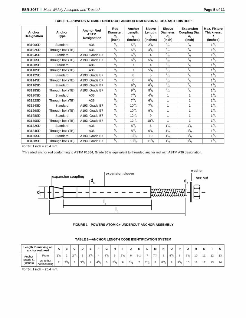
The Powers Atomic+ Undercut Anchors are displacement controlled undercut anchors. The Powers Atomic+ Undercut Anchors are comprised of five components as shown in Figure 1. The expanded anchor sleeve creates a mechanical interlock with the surrounding concrete. The Powers Atomic+ Undercut Anchors are available in standard (A36 and A193 designations) and through- bolted (A36-TB and A193-TB designations) versions with component dimensions as listed in Table 1. Sizes available include 3/8-inch (9.5 mm), 1/2-inch (12.7 mm), 5/8-inch (15.9 mm), and 3/4-inch (19.1 mm) diameters and various lengths. Table 1 shows anchor dimensions.
3.2 Anchor Materials:
3.2.1 Threaded Rods: The steel threaded rods used with the low-strength (A36 designation) anchors are ASTM A36 (F1554 Grade 36) low carbon steel and have a minimum 0.0002-inch (5 µm) zinc plating in accordance with ASTM B633, Type I. The steel threaded rods used with the high-strength (A193 designation) anchors comply with ASTM A193 Grade B7 and have a minimum 0.0002-inch (5 µm) yellow zinc plating in accordance with ASTM B633, Type II. A painted red setting mark (used for visual setting control) is provided on the threaded rod of both the low- and high-strength anchors.
3.2.2 Sleeves: The steel expansion sleeves comply with ASTM A513 Type 5 ERW DOM, with a minimum yield strength of 70,000 psi (483 MPa) and a minimum tensile strength of 80,000 psi (552 MPa). The sleeves have a minimum 0.0002-inch-thick (5 µm) yellow zinc plating in accordance with ASTM B633, Type II.
3.2.3 Coupling: The steel expansion couplings comply with ASTM A108 Type 12L14.
3.2.4 Nut and Washer: The hex nuts comply with ASTM A563, Grade A. The washers comply with ASTM F844.
3.3 Concrete:
Normal-weight and sand-lightweight concrete must conform to Sections 1903 and 1905 of the IBC, as applicable.
*Revised August 2015
ESR-3067 | Most Widely Accepted and Trusted Page 2 of 11 4.0 DESIGN AND INSTALLATION
4.1 Strength Design:
4.1.1 Design strength of anchors complying with the 2015 IBC, as well as Section R301.1.3 of the 2015 IRC must be determined in accordance with ACI 318-14 Chapter 17 and this report.
Design strength of anchors complying with the 2012 IBC and Section R301.1.3 of the 2012 IRC, must be determined in accordance with ACI 318-11 Appendix D and this report.
Design strength of anchors complying with the 2009 IBC and Section R301.1.3 of 2009 IRC must be in accordance with ACI 318-08 Appendix D and this report.
Design strength of anchors complying with the 2006 IBC and Section R301.1.3 of 2006 IRC must be in accordance with ACI 318-05 Appendix D and this report.
Design examples according to the 2015 IBC and 2012 IBC are given in Figures 5, 6, and 7 of this report. Design parameters are described in Tables 4 and 5 of this report and are based on the 2015 IBC (ACI 318-14) and 2012 IBC (ACI 318-11) unless noted otherwise in Sections 4.1.1 through 4.1.12. The strength design of anchors must comply with ACI 318-14 17.3.1 or ACI 318-11 D.4.1, except as required in ACI 318-14 17.2.3 or ACI 318-11 D.3.3, as applicable.
Strength reduction factors, , as given in ACI 318-14 17.3.3 or ACI 318-11 D.4.3, as applicable, and Table 4 must be used for load combinations calculated in accordance with Section 1605.2 of the IBC and Section 5.3 of ACI 318-14 or Section 9.2 of ACI 318-11, as applicable. Strength reduction factors, , as given in ACI 318-11 D.4.4 must be used for load combinations calculated in accordance with ACI 318-11 Appendix C.
The value of f′c used in the calculations must be limited to a maximum of 8,000 psi (55.2 MPa), in accordance with ACI 318-14 17.2.7 or ACI 318-11 D.3.7, as applicable.
4.1.2 Requirements for Static Steel Strength in Tension, Nsa: The nominal steel strength of a single anchor in tension, Nsa, must be calculated in accordance with ACI 318-14 17.4.2.1 or ACI 318-11 D.5.1.2, as applicable. The resulting values of Nsa are described in Table 4 of this report. Strength reduction factors, , corresponding to ductile steel elements may be used.
4.1.3 Requirements for Static Concrete Breakout Strength in Tension, Ncb or Ncbg: The nominal concrete breakout strength of a single anchor or group of anchors in tension, Ncb and Ncbg, respectively, must be calculated in accordance with ACI 318-14 17.4.2 or ACI 318-11 D.5.2, as applicable, and modifications as described in this section. The basic concrete breakout strength of a single anchor in tension in regions where analysis indicates cracking, Nb, must be calculated according to ACI 318-14 17.4.2.2 or ACI 318-11 D.5.2.2, as applicable, using the values of hef and kcr as described in Table 4 of this report. Concrete breakout strength in tension in regions where analysis indicates no cracking in accordance with ACI 318-14 17.4.2.6 or ACI 318-11 D.5.2.6, as applicable, must be calculated with Ψc,N = 1.0 and using the value of kuncr as given in Table 4 of this report.
4.1.4 Requirements for Static Pullout Strength in Tension, Npn: The nominal pullout strength of a single anchor or a group of anchors in tension, in accordance with ACI 318-14 17.4.3 or ACI 318-11 D.5.3, as applicable, in cracked concrete, Np,cr, is given in Table 4 of this report. For all design cases, Ψc,P =1.0. In accordance with ACI 318-14 17.4.3.2 or ACI 318-11 D.5.3.2, as applicable, the
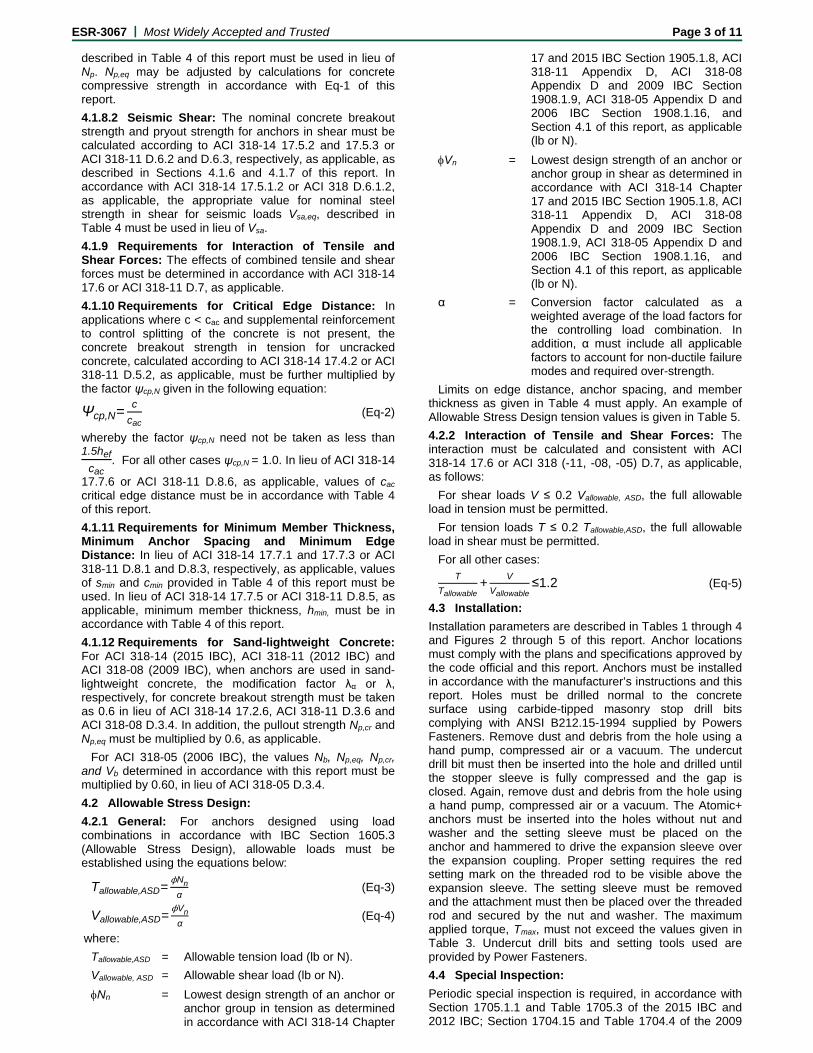
nominal pullout strength in cracked concrete must be adjusted by calculation according to Eq-1:
, , , (lb, psi) (Eq-1)
, , . (N, MPa)
In uncracked concrete, pullout strength does not control and therefore need not be evaluated.
4.1.5 Requirements for Static Steel Strength in Shear, Vsa: The nominal steel strength in shear, Vsa, of a single anchor in accordance with ACI 318-14 17.5.1.2 or ACI 318-11 D.6.1.2, as applicable, is given in Table 4 for the standard type and through-bolt type anchors and must be used in lieu of the values derived by calculation from ACI 318-14 Eq. 17.5.1.2b or ACI 318-11 Eq. D-29, as applicable. Strength reduction factors, , corresponding to ductile steel elements must be used.
4.1.6 Requirements for Static Concrete Breakout Strength in Shear, Vcb or Vcbg: The nominal static concrete breakout strength of a single anchor or a group of anchors in shear, Vcb or Vcbg, respectively, must be calculated in accordance with ACI 318-14 17.5.2 or ACI 318-11 D.6.2, as applicable, with modifications as described in this section. The basic concrete breakout strength of a single anchor in shear must be calculated in accordance with ACI 318-14 17.5.2.2 or ACI 318-11 D.6.2.2, as applicable, where the value of le used in ACI 318-14 Eq. 17.5.2.2a or ACI 318-11 Eq. D-33, as applicable, must be taken as hef, but no greater than 8da, for the anchors with one tubular shell over full length of the embedment depth; or the value of le used in ACI 318-14 Eq. 17.5.2.2a or ACI 318-11 Eq. D-33, as applicable, must be taken as 2da for the anchors with a distance sleeve separated from the expansion sleeve.
4.1.7 Requirements for Static Concrete Pryout Strength in Shear, Vcp or Vcpg: The nominal static concrete pryout strength of a single anchor or a group of anchors in shear, Vcp or Vcpg, respectively, must be calculated in accordance with ACI 318-14 17.5.3 or ACI 318-11 D.6.3, as applicable, modified by using the value kcp provided in Table 4 and the value Ncb and Ncbg as calculated in Section 4.1.3 of this report.
4.1.8 Requirements for Seismic Design: General: For load combinations including seismic, the design must be performed in accordance with ACi 318-14 17.2.3 or ACI 318-11 D.3.3, as applicable. Modifications to ACI 318-14 17.2.3 shall be applied under Section 1905.1.8 of the 2015 IBC. For the 2012 IBC, Section 1905.1.9 shall be omitted. Modifications to ACI 318 D.3.3 must be applied under Section 1908.1.9 of the 2009 IBC or Section 1908.1.16 of the 2006 IBC, as applicable.
The A36, A36-TB, A193, and A193-TB designated anchors comply with ACI 318-14 2.3 or ACI 318-11 D.1, as applicable, as ductile steel elements and must be designed in accordance with ACI 318-14, 17.2.3.4, 17.2.3.5, 17.2.3.6 or 17.2.3.7; ACI 318-11 D.3.3.4, D.3.3.5, D.3.3.6, and D.3.3.7; ACI 318-08 D.3.3.4, D.3.3.5, or D.3.3.6; or ACI 318-05 D.3.3.4 or D.3.3.5, as applicable.
4.1.8.1 Seismic Tension: The nominal steel strength and nominal concrete breakout strength for anchors in tension must be calculated in accordance with ACI 318-14 17.4.1 and 17.4.2 or ACI 318-11 D.5.1 and D.5.2, respectively, as applicable, as described in Sections 4.1.2 and 4.1.3 of this report. In accordance with ACI 318-14 17.4.3.2 or ACI 318-11 D.5.3.2, as applicable, the appropriate value for pullout strength in tension for seismic loads, Np,eq,
ESR-3067 | Most Widely Accepted and Trusted Page 3 of 11
described in Table 4 of this report must be used in lieu of Np. Np,eq may be adjusted by calculations for concrete compressive strength in accordance with Eq-1 of this report.
4.1.8.2 Seismic Shear: The nominal concrete breakout strength and pryout strength for anchors in shear must be calculated according to ACI 318-14 17.5.2 and 17.5.3 or ACI 318-11 D.6.2 and D.6.3, respectively, as applicable, as described in Sections 4.1.6 and 4.1.7 of this report. In accordance with ACI 318-14 17.5.1.2 or ACI 318 D.6.1.2, as applicable, the appropriate value for nominal steel strength in shear for seismic loads Vsa,eq, described in Table 4 must be used in lieu of Vsa.
4.1.9 Requirements for Interaction of Tensile and Shear Forces: The effects of combined tensile and shear forces must be determined in accordance with ACI 318-14 17.6 or ACI 318-11 D.7, as applicable.
4.1.10 Requirements for Critical Edge Distance: In applications where c < cac and supplemental reinforcement to control splitting of the concrete is not present, the concrete breakout strength in tension for uncracked concrete, calculated according to ACI 318-14 17.4.2 or ACI 318-11 D.5.2, as applicable, must be further multiplied by the factor ψcp,N given in the following equation:
Ψcp,N=c
cac (Eq-2)
whereby the factor ψcp,N need not be taken as less than 1.5hef
cac. For all other cases ψcp,N = 1.0. In lieu of ACI 318-14
17.7.6 or ACI 318-11 D.8.6, as applicable, values of cac critical edge distance must be in accordance with Table 4 of this report.
4.1.11 Requirements for Minimum Member Thickness, Minimum Anchor Spacing and Minimum Edge Distance: In lieu of ACI 318-14 17.7.1 and 17.7.3 or ACI 318-11 D.8.1 and D.8.3, respectively, as applicable, values of smin and cmin provided in Table 4 of this report must be used. In lieu of ACI 318-14 17.7.5 or ACI 318-11 D.8.5, as applicable, minimum member thickness, hmin, must be in accordance with Table 4 of this report.
4.1.12 Requirements for Sand-lightweight Concrete: For ACI 318-14 (2015 IBC), ACI 318-11 (2012 IBC) and ACI 318-08 (2009 IBC), when anchors are used in sand-lightweight concrete, the modification factor λα or λ, respectively, for concrete breakout strength must be taken as 0.6 in lieu of ACI 318-14 17.2.6, ACI 318-11 D.3.6 and ACI 318-08 D.3.4. In addition, the pullout strength Np,cr and Np,eq must be multiplied by 0.6, as applicable.
For ACI 318-05 (2006 IBC), the values Nb, Np,eq, Np,cr, and Vb determined in accordance with this report must be multiplied by 0.60, in lieu of ACI 318-05 D.3.4.
4.2 Allowable Stress Design:
4.2.1 General: For anchors designed using load combinations in accordance with IBC Section 1605.3 (Allowable Stress Design), allowable loads must be established using the equations below:
Tallowable,ASD=ϕNn
α (Eq-3)
Vallowable,ASD=ϕVn
α (Eq-4)
where:
Tallowable,ASD = Allowable tension load (lb or N).
Vallowable, ASD = Allowable shear load (lb or N).
Nn = Lowest design strength of an anchor or anchor group in tension as determined in accordance with ACI 318-14 Chapter
17 and 2015 IBC Section 1905.1.8, ACI 318-11 Appendix D, ACI 318-08 Appendix D and 2009 IBC Section 1908.1.9, ACI 318-05 Appendix D and 2006 IBC Section 1908.1.16, and Section 4.1 of this report, as applicable (lb or N).
Vn = Lowest design strength of an anchor or anchor group in shear as determined in accordance with ACI 318-14 Chapter 17 and 2015 IBC Section 1905.1.8, ACI 318-11 Appendix D, ACI 318-08 Appendix D and 2009 IBC Section 1908.1.9, ACI 318-05 Appendix D and 2006 IBC Section 1908.1.16, and Section 4.1 of this report, as applicable (lb or N).
α = Conversion factor calculated as a weighted average of the load factors for the controlling load combination. In addition, α must include all applicable factors to account for non-ductile failure modes and required over-strength.
Limits on edge distance, anchor spacing, and member thickness as given in Table 4 must apply. An example of Allowable Stress Design tension values is given in Table 5.
4.2.2 Interaction of Tensile and Shear Forces: The interaction must be calculated and consistent with ACI 318-14 17.6 or ACI 318 (-11, -08, -05) D.7, as applicable, as follows:
For shear loads V ≤ 0.2 Vallowable, ASD, the full allowable load in tension must be permitted.
For tension loads T ≤ 0.2 Tallowable,ASD, the full allowable load in shear must be permitted.
For all other cases: T
Tallowable+
V
Vallowable≤1.2 (Eq-5)
4.3 Installation:
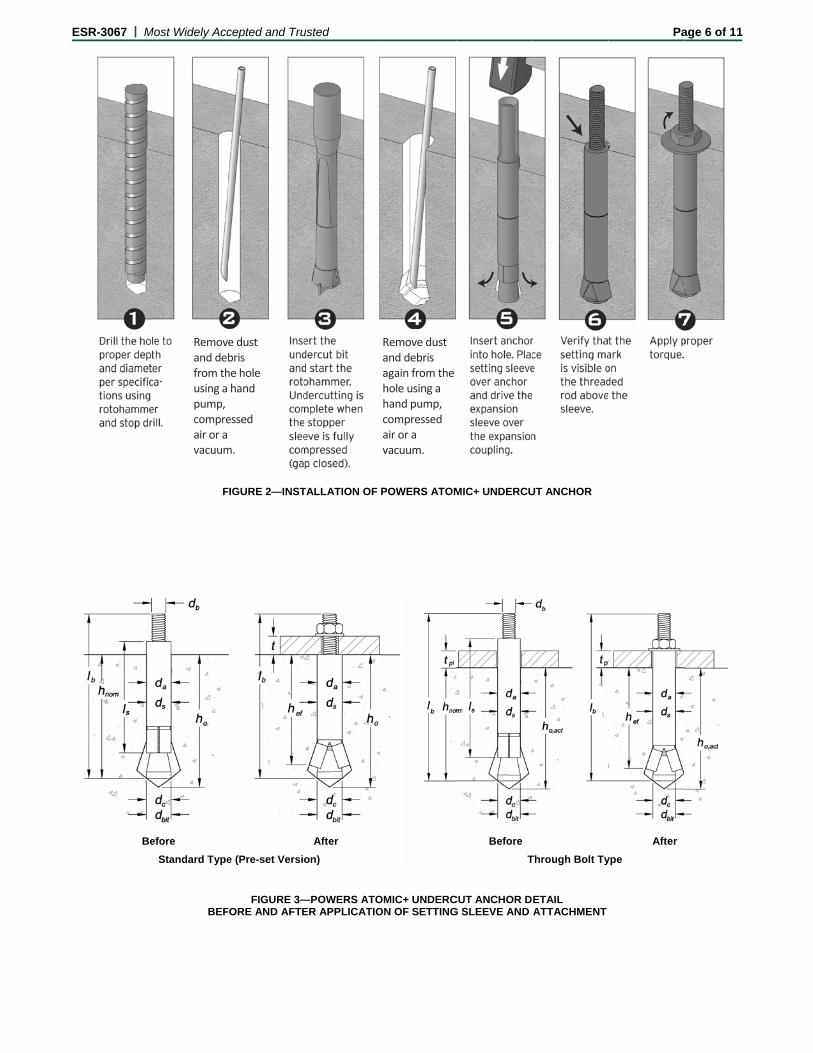
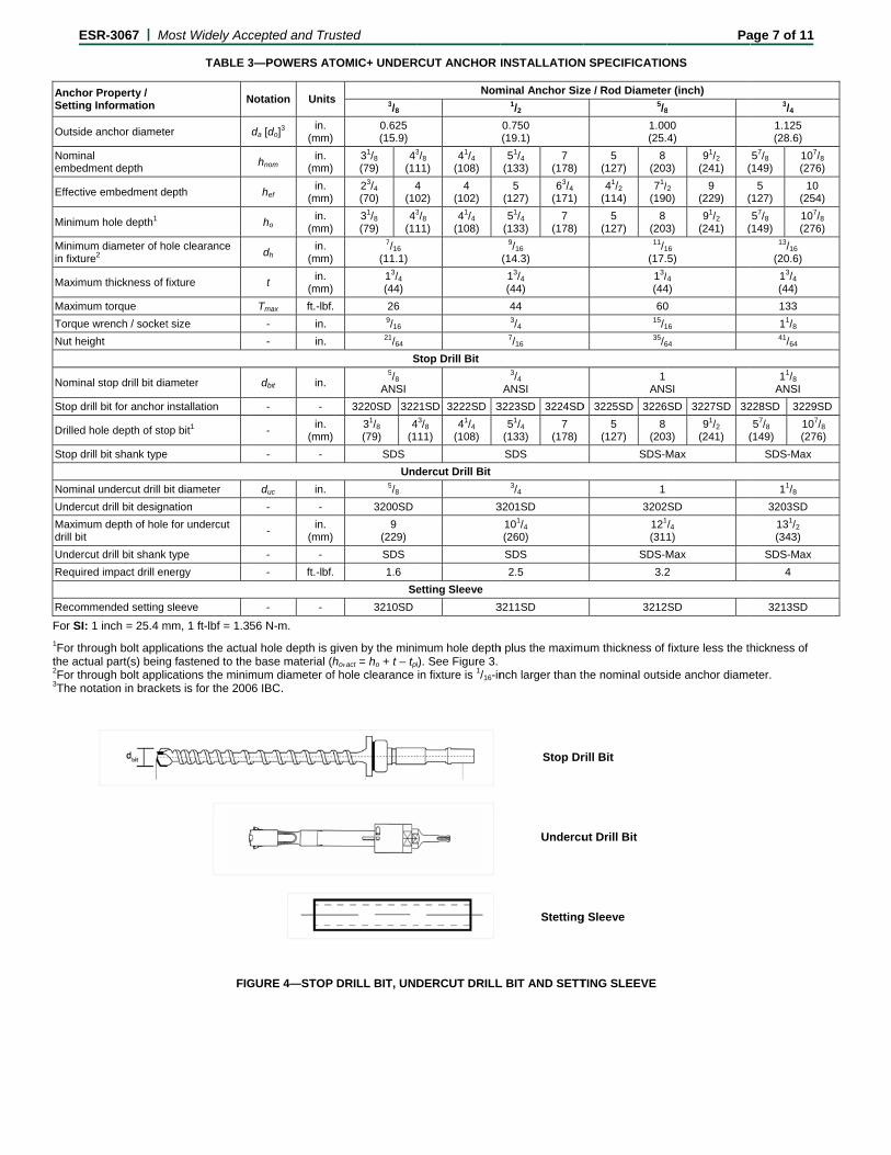
Installation parameters are described in Tables 1 through 4 and Figures 2 through 5 of this report. Anchor locations must comply with the plans and specifications approved by the code official and this report. Anchors must be installed in accordance with the manufacturer’s instructions and this report. Holes must be drilled normal to the concrete surface using carbide-tipped masonry stop drill bits complying with ANSI B212.15-1994 supplied by Powers Fasteners. Remove dust and debris from the hole using a hand pump, compressed air or a vacuum. The undercut drill bit must then be inserted into the hole and drilled until the stopper sleeve is fully compressed and the gap is closed. Again, remove dust and debris from the hole using a hand pump, compressed air or a vacuum. The Atomic+ anchors must be inserted into the holes without nut and washer and the setting sleeve must be placed on the anchor and hammered to drive the expansion sleeve over the expansion coupling. Proper setting requires the red setting mark on the threaded rod to be visible above the expansion sleeve. The setting sleeve must be removed and the attachment must then be placed over the threaded rod and secured by the nut and washer. The maximum applied torque, Tmax, must not exceed the values given in Table 3. Undercut drill bits and setting tools used are provided by Power Fasteners.
4.4 Special Inspection:
Periodic special inspection is required, in accordance with Section 1705.1.1 and Table 1705.3 of the 2015 IBC and 2012 IBC; Section 1704.15 and Table 1704.4 of the 2009
ESR-3067 | Most Widely Accepted and Trusted Page 4 of 11
IBC; or Section 1704.13 of the 2006 IBC, as applicable. The special inspector must make periodic inspections during anchor installation to verify anchor type, anchor dimensions, concrete type, concrete compressive strength, hole dimensions, hole cleaning procedure, anchor spacing, edge distances, concrete thickness, anchor embedment, tightening torque and adherence to the manufacturer’s printed installation instructions. The special inspector must be present as often as required in accordance with the “statement of special inspection.” Under the IBC, additional requirements as set forth in Chapter 17 must be observed, where applicable.
5.0 CONDITIONS OF USE
The Powers Atomic+ Undercut Anchors described in this report comply with, or are suitable alternatives to what is specified in, those codes listed in Section 1.0 of this report, subject to the following conditions:
5.1 Anchor sizes, dimensions, and minimum embedment depths are as set forth in the tables of this report.
5.2 The anchors must be installed in accordance with the manufacturer’s published installation instructions and this report. In cases of a conflict, this report governs.
5.3 Anchors must be limited to use in concrete with a specified strength, f′c, from 2,500 to 8,500 psi (17.2 to 58.6 MPa).
5.4 The values of f′c used for calculation purposes must not exceed 8,000 psi (55.1 MPa).
5.5 Strength design values must be established in accordance with Section 4.1 of this report.
5.6 Allowable stress design values must be established in accordance with Section 4.2 of this report.
5.7 Anchor spacing and edge distance, as well as minimum member thickness, must comply with Table 4 of this report.
5.8 Prior to installation, calculations and details demonstrating compliance with this report must be submitted to the code official for approval. The calculations and details must be prepared by a registered design professional where required by the statutes of the jurisdiction in which the project is to be constructed.
5.9 Since an ICC-ES acceptance criteria for evaluating data to determine the performance of undercut anchors subjected to fatigue or shock loading is unavailable at this time, the use of these anchors under these conditions is beyond the scope of the report.
5.10 Anchors may be installed in regions of concrete where cracking has occurred or where analysis indicates cracking may occur (ft > fr), subject to the conditions of this report.
5.11 Anchors may be used to resist short-term loading due to wind or seismic forces, subject to the conditions of this report.
5.12 Where not otherwise prohibited in the code, anchors are permitted for installation in fire-resistance rated construction provided that at least one of the following conditions is fulfilled:
Anchors are used to resist wind or seismic forces only.
Anchors that support a fire-resistance-rated envelope or a fire-resistance-rated membrane are protected by approved fire-resistance-rated materials, or have been evaluated for resistance to fire exposure in accordance with recognized standards.
Anchors are used to support nonstructural elements.
5.13 Use of zinc-coated carbon steel anchors must be limited to dry, interior locations.
5.14 Special inspection must be provided in accordance with Section 4.4.
5.15 Anchors are manufactured under an approved quality control program with inspections by ICC-ES.
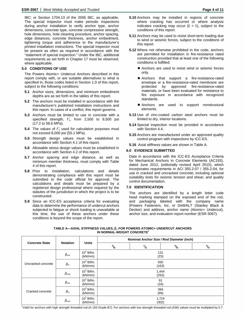
5.16 Axial stiffness values are shown in Table A.
6.0 EVIDENCE SUBMITTED
Data in accordance with the ICC-ES Acceptance Criteria for Mechanical Anchors in Concrete Elements (AC193), dated June 2012, (editorially revised April 2015), which incorporates requirements in ACI 355.2-07 / 355.2-04, for use in cracked and uncracked concrete; including optional suitability tests for seismic tension and shear; and quality control documentation.
7.0 IDENTIFICATION
The anchors are identified by a length letter code head marking stamped on the exposed end of the rod, and packaging labeled with the company name (Powers Fasteners, Inc. or DeWALT (Stanley Black & Decker) and address, anchor name (Atomic+ Undercut), anchor size, and evaluation report number (ESR-3067).
TABLE A—AXIAL STIFFNESS VALUES, , FOR POWERS ATOMIC+ UNDERCUT ANCHORS IN NORMAL-WEIGHT CONCRETE1
Concrete State Notation Units Nominal Anchor Size / Rod Diameter (inch)
3/8 1/2
5/8 3/4
Uncracked concrete
βmin 103 lbf/in. (kN/mm)
131 (23)
βm 103 lbf/in. (kN/mm)
930 (163)
βmax 103 lbf/in. (kN/mm)
1,444 (253)
Cracked concrete
βmin 103 lbf/in. (kN/mm)
91 (16)
βm 103 lbf/in. (kN/mm)
394 (69)
βmax 103 lbf/in. (kN/mm)
1,724 (302)
1Valid for anchors with high strength threaded rod (A 193 Grade B7). For anchors with low strength threaded rod (A36) values must be multiplied by 0.7.
E
F
1T
F
ESR-3067 | M
Anchor Designation
03100SD
03102SD
03104SD
03106SD
03108SD
03110SD
03112SD
03114SD
03116SD
03118SD
03120SD
03122SD
03124SD
03126SD
03128SD
03130SD
03132SD
03134SD
03136SD
03138SD
For SI: 1 inch = 2
Threaded ancho
Length ID markinanchor rod hea
Anchor length, lb, (inches)
Fro
Up tonot inc
For SI: 1 inch = 2
Most Widely Acc
TABLE 1—
Anchor Type
Standard
Through bolt (
Standard
Through bolt (
Standard
Through bolt (
Standard
Through bolt (
Standard
Through bolt (
Standard
Through bolt (
Standard
Through bolt (
Standard
Through bolt (
Standard
Through bolt (
Standard
Through bolt (
25.4 mm.
or rod conforming
ng on ad
A B
om 11/2 2
o but luding
2 21/2
25.4 mm.
cepted and Tru
—POWERS ATO
AnchoAST
Design
A3
(TB) A3
A193, G
(TB) A193, G
A3
(TB) A3
A193, G
(TB) A193, G
A193, G
(TB) A193, G
A3
(TB) A3
A193, G
(TB) A193, G
A193, G
(TB) A193, G
A3
(TB) A3
A193, G
(TB) A193, G
g to ASTM F1554
FIGURE 1—P
TABLE 2—A
C D E
21/2 3 31/2
3 31/2 4
usted
OMIC+ UNDERC
or Rod TM nation
RoDiam
d(inc
36 3/
36 3/
rade B7 3/
rade B7 3/
36 1/
36 1/
rade B7 1/
rade B7 1/
rade B7 1/
rade B7 1/
36 5/
36 5/
rade B7 5/
rade B7 5/
rade B7 5/
rade B7 5/
36 3/
36 3/
rade B7 3/
rade B7 3/
4, Grade 36 is eq
POWERS ATOM
ANCHOR LENG
F G H
2 4 41/2 5
41/2 5 51
CUT ANCHOR D
od meter,db ch)
AnchorLength
lb
(inches
/8 51/2
/8 51/2
/8 63/4
/8 63/4
/2 7
/2 7
/2 8
/2 8
/2 93/4
/2 93/4
/8 73/4
/8 73/4
/8 103/4
/8 103/4
/8 121/4
/8 121/4
/4 85/8
/4 85/8
/4 135/8
/4 135/8
quivalent to threa
MIC+ UNDERCUT
GTH CODE IDEN
H I J
5 51/2 6 6
/2 6 61/2
DIMENSIONAL C
r h,
s)
Sleeve Length,
ls (inches)
D
23/4
41/2
4
53/4
4
53/4
5
63/4
63/4
81/2
41/2
61/4
71/2
91/4
9
103/4
5
63/4
10
113/4
aded anchor rod
T ANCHOR ASS
NTIFICATION SY
K L M
61/2 7 71/2
7 71/2 8
CHARACTERIST
Sleeve Diameter,
ds (inch)
ExCou
5/8 5/8 5/8 5/8 3/4 3/4 3/4 3/4 3/4 3/4
1
1
1
1
1
1
11/8
11/8
11/8
11/8
with ASTM A36
SEMBLY
YSTEM
N O P
8 81/2 9
81/2 9 91/2
Pa
TICS1
xpansion upling Dia.,
dc (inch)
MaT
5/8 5/8 5/8 5/8 3/4 3/4 3/4 3/4 3/4 3/4
1
1
1
1
1
1
11/8
11/8
11/8
11/8
designation.
Q R S
91/2 10 11
10 11 12
age 5 of 11
ax. Fixture hickness,
t (inches)
13/4
13/4
13/4
13/4
13/4
13/4
13/4
13/4
13/4
13/4
13/4
13/4
13/4
13/4
13/4
13/4
13/4
13/4
13/4
13/4
T U
12 13
13 14
E ESR-3067 | M
Be
Most Widely Acc
F
efore
Standard Type
BEF
Removand debfrom thusing a pump, compreair or a vacuum
cepted and Tru
FIGURE 2—INST
e (Pre-set Versio
FIGURE 3—FORE AND AFTE
e dust bris he hole hand
essed
m.
usted
TALLATION OF
After
on)
—POWERS ATOER APPLICATIO
POWERS ATOM
OMIC+ UNDERCON OF SETTING
Remove dust and debris again from the hole using a hand pump, compressed air or a vacuum.
MIC+ UNDERCU
Before
T
CUT ANCHOR DG SLEEVE AND
UT ANCHOR
Through Bolt Ty
ETAIL ATTACHMENT
Pa
After
ype
age 6 of 11
E
AnchoSettin
Outsid
Nominembed
Effect
Minim
Minimin fixtu
Maxim
Maxim
Torqu
Nut he
Nomin
Stop d
Drilled
Stop d
Nomin
Under
Maximdrill bi
Under
Requi
Recom
For SI
1For ththe ac2For th3The n
ESR-3067 | M
or Property / ng Information
de anchor diamete
nal dment depth
ive embedment d
um hole depth1
um diameter of houre2
mum thickness of f
mum torque
e wrench / socket
eight
nal stop drill bit dia
drill bit for anchor
d hole depth of sto
drill bit shank type
nal undercut drill b
rcut drill bit design
mum depth of holet
rcut drill bit shank
red impact drill en
mmended setting
I: 1 inch = 25.4 m
hrough bolt applictual part(s) beinghrough bolt applinotation in bracke
Most Widely Acc
TABLE 3
N
er
epth
ole clearance
fixture
t size
ameter
installation
op bit1
e
bit diameter
nation
e for undercut
type
nergy
sleeve
mm, 1 ft-lbf = 1.35
cations the actuag fastened to thecations the minimets is for the 200
Sto
FIG
cepted and Tru
3—POWERS AT
Notation Units
da [do]3
in. (mm)
hnom in.
(mm)
hef in.
(mm)
ho in.
(mm)
dh in.
(mm)
t in.
(mm)
Tmax ft.-lbf.
- in.
- in.
dbit in.
- -
- in.
(mm)
- -
duc in.
- -
- in.
(mm)
- -
- ft.-lbf.
- -
56 N-m.
al hole depth is ge base material (hmum diameter of06 IBC.
op
GURE 4—STOP
usted
TOMIC+ UNDER
s 3/8
0.625(15.9)
31/8 (79)
43
(11
23/4 (70)
4(10
31/8 (79)
43
(117/16
(11.1)
13/4
(44)
26 9/16 21/64
S5/8
ANSI
3220SD 322
31/8 (79)
4(1
SDS
Und5/8
3200SD
9 (229)
SDS
1.6
Se
3210SD
given by the miniho,act = ho + t – tpl
f hole clearance
DRILL BIT, UN
RCUT ANCHOR
Nom
3/8
11) 41/4
(108)
4 02)
4 (102)
3/8
11) 41/4
(108)
Stop Drill Bit
21SD 3222SD 3
43/8
11) 41/4
(108)
dercut Drill Bit
3
etting Sleeve
3
mum hole depthl). See Figure 3.in fixture is 1/16-in
DERCUT DRILL
INSTALLATION
minal Anchor Siz1/2
0.750 (19.1)
51/4
(133) 7
(178)
5 (127)
63/4(171)
51/4
(133) 7
(178) 9/16
(14.3)
13/4
(44)
44 3/4 7/16
3/4
ANSI
3223SD 3224SD
51/4
(133) 7
(178)
SDS
3/4
3201SD
101/4
(260)
SDS
2.5
3211SD
h plus the maxim
nch larger than t
L BIT AND SETT
Undercu
Stop Dr
Stetting
N SPECIFICATIO
ze / Rod Diamete5/8
1.00(25.
5 (127)
8 (203
41/2 (114)
71/(190
5 (127)
8 (20311/1
(17.
13/(44
6015/135/6
1 ANS
D 3225SD 3226
5 (127)
8 (203
SDS-M
1
3202
121
(311
SDS-M
3.2
3212
um thickness of
he nominal outsi
TING SLEEVE
ut Drill Bit
rill Bit
g Sleeve
Pa
ONS
r (inch)
8
00 4)
3) 91/2
(241) (
/2 0)
9 (229) (
3) 91/2
(241) (
6 5)
/4
4)
0
6
64
SI
SD 3227SD 32
3) 91/2
(241) (
Max
SD
/4
1)
Max
2
SD
fixture less the t
ide anchor diame
age 7 of 11
3/4
1.125 (28.6)
57/8
(149) 107/8
(276)
5 (127)
10 (254)
57/8
(149) 107/8
(276) 13/16
(20.6)
13/4
(44)
133
11/8 41/64
11/8
ANSI
228SD 3229SD
57/8
(149) 107/8
(276)
SDS-Max
11/8
3203SD
131/2
(343)
SDS-Max
4
3213SD
hickness of
eter.
ESR-3067 | Most Widely Accepted and Trusted Page 8 of 11
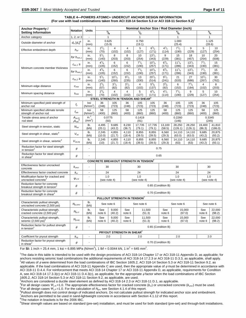
TABLE 4—POWERS ATOMIC+ UNDERCUT ANCHOR DESIGN INFORMATION (For use with load combinations taken from ACI 318-14 Section 5.3 or ACI 318-11 Section 9.2)1
Anchor Property / Setting Information
Notation Units Nominal Anchor Size / Rod Diameter (inch)
3/8 1/2
5/8 3/4
Anchor category 1, 2, or 3 - 1 1 1 1
Outside diameter of anchor da [do]8
in. (mm)
0.625 (15.9)
0.750 (19.1)
1.000 (25.4)
1.125 (28.6)
Effective embedment depth hef in.
(mm) 23/4 (70)
4 (102)
4 (102)
5 (127)
63/4 (171)
41/2 (114)
71/2 (190)
9 (229)
5 (127)
10 (254)
Minimum concrete member thickness
for hmin,1 in.
(mm) 51/2
(140) 8
(203) 8
(203) 10
(254) 131/2 (343)
9 (229)
15 (381)
18 (457)
10 (254)
20 (508)
cac,1 ≥ in.
(mm) 41/8
(105) 6
(152) 6
(152) 71/2
(190) 101/8 (257)
63/4 (171)
111/4 (286)
131/2 (343)
71/2 (190)
15 (381)
for hmin,2 in.
(mm) 43/8
(105) 6
(152) 6
(152) 71/2
(190) 101/8 (257)
63/4 (171)
111/4 (286)
131/2 (343)
71/2 (190)
15 (381)
cac,2 ≥ in.
(mm) 51/2
(140) 101/4 (260)
91/4 (235)
13 (330)
201/4 (514)
91/2 (241)
21 (533)
27 (686)
101/2 (267)
30 (762)
Minimum edge distance cmin in.
(mm) 21/4 (57)
31/4 (82)
31/4 (82)
4 (102)
53/8 (137)
33/8 (92)
6 (152)
71/4 (184)
4 (102)
8 (203)
Minimum spacing distance smin in.
(mm) 23/4 (70)
4 (102)
4 (102)
5 (127)
63/4 (171)
41/2 (114)
71/2 (190)
9 (229)
5 (127)
10 (254)
STEEL STRENGTH IN TENSION AND SHEAR3
Minimum specified yield strength of anchor rod fy
ksi (N/mm2)
36 (248)
105 (723)
36 (248)
105 (723)
105 (723)
36 (248)
105 (723)
105 (723)
36 (248)
105 (723)
Minimum specified ultimate tensile strength of anchor rod futa
ksi (N/mm2)
58 (400)
125 (860)
58 (400)
125 (860)
125 (860)
58 (400)
125 (860)
125 (860)
58 (400)
125 (860)
Tensile stress area of anchor rod steel
Ase,N
[Ase]8
in.2 (mm2)
0.0775 (50)
0.1419 (91)
0.2260 (146)
0.3345 (245)
Steel strength in tension, static Nsa lb.
(kN) 4,495 (20.1)
9,685 (43.2)
8,230 (36.7)
17,735 (79.1)
17,735 (79.1)
13,100 (58.5)
28,250 (126.1)
28,250 (126.1)
19,400 (86.3)
41,810 (186.0)
Steel strength in shear, static9 Vsa lb.
(kN) 2,245 (10.0)
4,855 (21.7)
4,110 (18.4)
8,855 (39.5)
8,855 (39.5)
6,560 (29.3)
14,110 (63.0)
14,110 (63.0)
9,685 (43.2)
20,875 (93.2)
Steel strength in shear, seismic9 Vsa,eq lb.
(kN) 2,245 (10)
4,855 (21.7)
4,110 (18.4)
8,855 (39.5)
8,855 (39.5)
6,560 (29.3)
14,110 (63)
14,110 (63)
9,685 (43.2)
20,875 (93.1)
Reduction factor for steel strength in tension2 - 0.75
Reduction factor for steel strength in shear2 - 0.65
CONCRETE BREAKOUT STRENGTH IN TENSION7
Effectiveness factor uncracked concrete kuncr - 30 30 30 30
Effectiveness factor cracked concrete kcr - 24 24 24 24
Modification factor for cracked and uncracked concrete4 ψc,N
- 1.0 (see note 4)
1.0 (see note 4)
1.0 (see note 4)
1.0 (see note 4)
Reduction factor for concrete breakout strength in tension2 - 0.65 (Condition B)
Reduction factor for concrete breakout strength in shear2 - 0.70 (Condition B)
PULLOUT STRENGTH IN TENSION7
Characteristic pullout strength, uncracked concrete (2,500 psi) Np,uncr
lb. (kN)
See note 6 See note 6 See note 6 See note 6
Characteristic pullout strength, cracked concrete (2,500 psi)5 Np,cr
lb. (kN)
See note 6
9,000 (40.2)
See note 6
11,500 (51.3)
See note 6
15,000 (67.0)
See note 6
22,000 (98.2)
Characteristic pullout strength, seismic (2,500 psi)5 Np,eq
lb. (kN)
See note 6
9,000 (40.2)
See note 6
11,500 (51.3)
See note 6
15,000 (67.0)
See note 6
22,000 (98.2)
Reduction factor for pullout strength in tension2 - 0.65 (Condition B)
PRYOUT STRENGTH IN SHEAR7
Coefficient for pryout strength kcp - 2.0 2.0 2.0 2.0
Reduction factor for pryout strength in shear2 - 0.70 (Condition B)
For SI: 1 inch = 25.4 mm, 1 ksi = 6.895 MPa (N/mm2), 1 lbf = 0.0044 kN, 1 in2 = 645 mm2.
1The data in this table is intended to be used with the design provisions of ACI 318-14 Chapter 17 or ACI 318-11 Appendix D, as applicable; for anchors resisting seismic load combinations the additional requirements of ACI 318-14 17.2.3 or ACI 318-11 D.3.3, as applicable, shall apply. 2All values of were determined from the load combinations of IBC Section 1605.2, ACI 318-14 Section 5.3 or ACI 318-11 Section 9.2, as applicable. If the load combinations of ACI 318-11 Appendix C are used, then the appropriate value of must be determined in accordance with ACI 318-11 D.4.4. For reinforcement that meets ACI 318-14 Chapter 17 or ACI 318-11 Appendix D, as applicable, requirements for Condition A, see ACI 318-14 17.3.3(c) or ACI 318-11 D.4.3(c), as applicable, for the appropriate factor when the load combinations of IBC Section 1605.2, ACI 318-14 Section 5.3 or ACI 318-11 Section 9.2, as applicable, are used. 3Anchors are considered a ductile steel element as defined by ACI 318-14 2.3 or ACI 318-11 D.1, as applicable. 4For all design cases Ψc,N =1.0. The appropriate effectiveness factor for cracked concrete (kcr) or uncracked concrete (kuncr) must be used. 5For all design cases Ψc,P =1.0. For the calculation of Npn, see Section 4.1.4 of this report. 6Pullout strength does not control design of indicated anchors. Do not calculate pullout strength for indicated anchor size and embedment. 7Anchors are permitted to be used in sand-lightweight concrete in accordance with Section 4.1.12 of this report. 8The notation in brackets is for the 2006 IBC. 9Shear strength values are based on standard (pre-set) installation, and must be used for both standard (pre-set) and through-bolt installations.
E
F
1
2
3
4
5
6
7 8 9
a
G
C
ESR-3067 | M
TA
Nominal Anch(inch)
3/8
1/2
5/8
3/4
For SI: 1 inch = 2
Single anchor wConcrete determLoad combinatio30% dead load aCalculation of wf’c = 2,500 psi (nca1 = ca2 ≥ cac. h ≥ hmin. Values are for C
applicable, is not
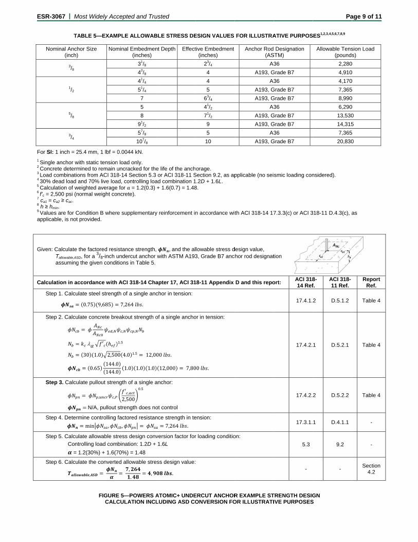
Given: Calculate Tallowable,AS
assuming
Calculation in ac
Step 1. Calcu
Step 2. Calcu
Step 3. Calcu
Step 4. Determ
Step 5. Calcu
Cont
=
Step 6. Calcu
Most Widely Acc
ABLE 5—EXAM
hor Size Nom
25.4 mm, 1 lbf = 0
with static tensionmined to remain uons from ACI 318and 70% live loa
weighted averagenormal weight co
Condition B whereprovided.
the factored resi
SD, for a 3/8-inch u
g the given condit
ccordance with
late steel strengt
0.75 9,685
late concrete bre
,
′
30 1.0 2,50
0.65144.0144.0
ulate pullout stren
, ,
N/A, pullout
mine controlling
min ,
late allowable st
trolling load com
1.2(30%) + 1.6(7
late the converte
,
FIGURECALC
cepted and Tru
PLE ALLOWAB
minal Embedmen(inches)
31/8
43/8
41/4
51/4
7
5
8
91/2
57/8
107/8
0.0044 kN.
n load only. uncracked for the8-14 Section 5.3
ad, controlling loa for α = 1.2(0.3) ncrete).
e supplementary
istance strength,undercut anchor tions in Table 5.
ACI 318-14 Cha
th of a single anc
7,264 .
eakout strength o
, ,
.
0 4.0 . 12,00
00
1.0 1.0 1.0
ngth of a single a
′ ,2,500
.
strength does no
factored resistan
,
ress design conv
bination: 1.2D +
70%) = 1.48
ed allowable stre
,.
,
E 5—POWERS ACULATION INCL
usted
BLE STRESS DE
nt Depth Effect
e life of the anchor ACI 318-11 S
ad combination 1+ 1.6(0.7) = 1.48
y reinforcement in
, and the alwith ASTM A193
apter 17, ACI 31
chor in tension:
of a single ancho
00 .
12,000 7,80
anchor:
ot control
nce strength in te
7,264 .
version factor for
1.6L
ess design value:
.
ATOMIC+ UNDELUDING ASD CO
ESIGN VALUES
tive Embedment(inches)
23/4
4
4
5
63/4
41/2
71/2
9
5
10
orage. Section 9.2, as ap
.2D + 1.6L. 8.
n accordance wi
lowable stress d3, Grade B7 anc
8-11 Appendix
or in tension:
00 .
ension:
r loading conditio
ERCUT ANCHORONVERSION FO
FOR ILLUSTRA
Anchor Rod (AS
A3
A193, G
A3
A193, G
A193, G
A3
A193, G
A193, G
A3
A193, G
pplicable (no sei
th ACI 318-14 17
design value, chor rod designat
D and this repo
on:
R EXAMPLE STOR ILLUSTRATI
ATIVE PURPOS
Designation STM)
36
Grade B7
36
Grade B7
Grade B7
36
Grade B7
Grade B7
36
Grade B7
smic loading con
7.3.3(c) or ACI 3
tion
ort: ACI 31814 Ref
17.4.1.
17.4.2.
17.4.2.
17.3.1.
5.3
-
TRENGTH DESIGIVE PURPOSES
Pa
SES1,2,3,4,5,6,7,8,9
Allowable Tens(pounds
2,280
4,910
4,170
7,365
8,990
6,290
13,530
14,315
7,365
20,830
nsidered).
318-11 D.4.3(c), a
8-f.
ACI 318-11 Ref.
2 D.5.1.2
1 D.5.2.1
2 D.5.2.2
1 D.4.1.1
9.2
-
GN S
age 9 of 11
sion Load s)
0
0
0
5
0
0
0
5
5
0
as
Report
Ref.
Table 4
Table 4
Table 4
-
-
Section 4.2
E
GivTwo Con No (C17.3Assseisrigid ha =hef =sa =ca1 =ca2 ≥
Calc
Ste
Ste
Ste
Ste
Ste
Ste
Ste
Ste
ca,m
Ste
Ste
Ste
Ste
Ste
Ste
ESR-3067 | M
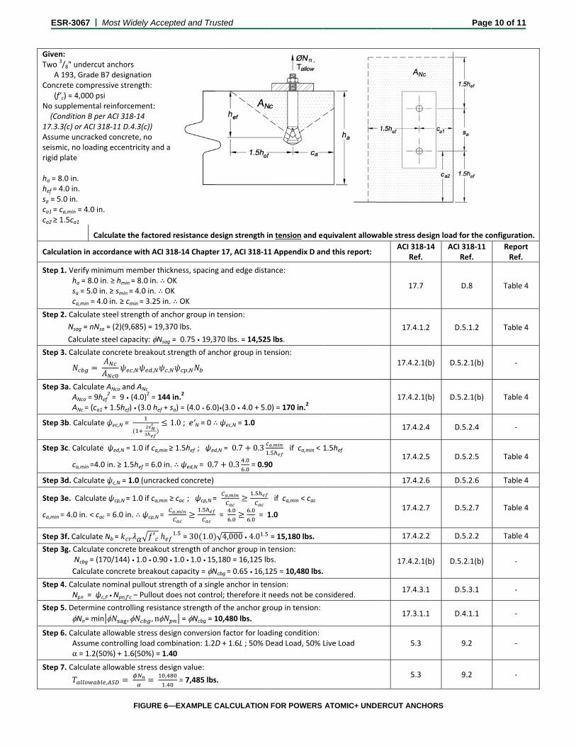
ven: o 3/8" undercut aA 193, Grade B7ncrete compress(f’c) = 4,000 psi supplemental reCondition B per A3.3(c) or ACI 318ume uncracked smic, no loadingd plate
= 8.0 in. = 4.0 in. = 5.0 in. = ca,min = 4.0 in. ≥ 1.5ca1
Calc
culation in acco
p 1. Verify minimha = 8.0 in.sa = 5.0 in. ca,min = 4.0
p 2. Calculate st
Nsag = nNsa =
Calculate st
p 3. Calculate co
p 3a. Calculate AANco = 9hef
2
ANc = (ca1 +
p 3b. Calculate ψ
p 3c. Calculate
ca,min =4.0 i
p 3d. Calculate ψ
p 3e. Calculate
min = 4.0 in. < cac =
p 3f. Calculate N
p 3g. Calculate c Ncbg = (170
Calculate c
p 4. Calculate noNpn = ψc,P
p 5. Determine
Nn= min
p 6. Calculate alAssume coα = 1.2(50%
p 7. Calculate al
,
Most Widely Acc
anchors 7 designation sive strength:
einforcement: ACI 318‐14 8‐11 D.4.3(c)) concrete, no eccentricity and
ulate the factor
rdance with AC
mum member th. ≥ hmin = 8.0 in. ∴≥ smin = 4.0 in. ∴in. ≥ cmin = 3.25
teel strength of a
= (2)(9,685) = 19
eel capacity: Noncrete breakou
, ,
ANco and ANc 2 = 9 • (4.0)2 = 1 1.5hef) • (3.0 hef
ψec,N =
ψed,N = 1.0 if ca,m
in. ≥ 1.5hef = 6.0
ψc,N = 1.0 (uncra
ψcp,N = 1.0 if ca,m
= 6.0 in. ∴ ψcp,N =
Nb = ′
concrete breako0/144) • 1.0 • 0.9
concrete breako
ominal pullout s
P • Npn,f’c – Pullout
controlling resis
, , n
lowable stress dontrolling load co%) + 1.6(50%) =
lowable stress d
FIGURE
cepted and Tru
d a
red resistance de
I 318‐14 Chapte
hickness, spacing∴ OK ∴ OK in. ∴ OK
anchor group in
9,370 lbs.
Nsag = 0.75 • 19,3
ut strength of an
, ,
44 in.2
f + sa) = (4.0 + 6.0
1.0 ; e’N = 0 ∴
min ≥ 1.5hef ; ψed
in. ∴ ψed,N = 0.7
acked concrete)
min ≥ cac ; ψcp,N =
= , .
. = 30 1.0
out strength of a90 • 1.0 • 1.0 • 15
ut capacity = Ntrength of a singt does not contr
tance strength o
= Ncbg = 1
design conversioombination: 1.2D1.40
design value: ,
. = 7,485 lbs
6—EXAMPLE C
usted
esign strength in
er 17, ACI 318‐11
g and edge dista
tension:
370 lbs. = 14,525
chor group in te
0)•(3.0 • 4.0 + 5.0
∴ ψec,N = 1.0
d,N = 0.7 0.3
7 0.3.
. = 0.90
= , .
= .
.
.
. = 1
√4,000 • 4.0 .
nchor group in t,180 = 16,125 lb
Ncbg = 0.65 • 16,1
gle anchor in tenrol; therefore it n
of the anchor gr
10,480 lbs.
on factor for loadD + 1.6L ; 50% D
s.
CALCULATION
n tension and eq
1 Appendix D an
ance:
5 lbs.
ension:
0) = 170 in.2
,
. if ca,min < 1
0
if ca,min < cac
1.0
= 15,180 lbs.
tension: bs.
25 = 10,480 lbs.
nsion: needs not be co
oup in tension:
ding condition:Dead Load, 50% L
FOR POWERS
quivalent allow
nd this report:
1.5hef
nsidered.
Live Load
ATOMIC+ UND
wable stress desi
ACI 318‐14Ref.
17.7
17.4.1.2
17.4.2.1(b
17.4.2.1(b
17.4.2.4
17.4.2.5
17.4.2.6
17.4.2.7
17.4.2.2
17.4.2.1(b
17.4.3.1
17.3.1.1
5.3
5.3
ERCUT ANCHO
Pag
gn load for the
4 ACI 318‐11Ref.
D.8
D.5.1.2
b) D.5.2.1(b)
b) D.5.2.1(b)
D.5.2.4
D.5.2.5
D.5.2.6
D.5.2.7
D.5.2.2
b) D.5.2.1(b)
D.5.3.1
D.4.1.1
9.2
9.2
ORS
ge 10 of 11
configuration.
1 Report Ref.
Table 4
Table 4
‐
Table 4
‐
Table 4
Table 4
Table 4
Table 4
‐
‐
‐
‐
‐
E
GivTwo Con No (C17.3Assseisrigid
ha =hef =sa =ca1 =ca2 ≥
Calc
Ste
Ste
Ste
Ste
Ste
Ste
Ste
Ste
Ste
Ste
Ste
Ste
Ste
Ste
ESR-3067 | M
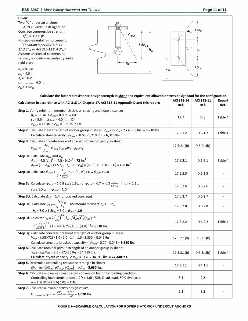
ven: o 3/8" undercut aA 193, Grade B7ncrete compress(f’c) = 3,000 psi supplemental reCondition B per A3.3(c) or ACI 318ume uncracked smic, no loadingd plate
= 8.0 in. = 4.0 in. = 5.0 in. = ca,min = 4.0 in. ≥ 1.5ca1
Calc
culation in acco
p 1. Verify minimha = 8.0 in.sa = 5.0 in. ca,min = 4.0
p 2. Calculate st
Calculate s
p 3. Calculate co
p 3a. Calculate AAVco = 4.5 (AVc = (1.5 c
p 3b. Calculate ψ
p 3c. Calculate
ca2 ≥ 1.5 ca
p 3d. Calculate ψ
p 3e. Calculate
ha = 8.0 ≥
p 3f. Calculate V
7.
.
p 3g. Calculate cVcbg = (108
Calculate c
p 4. Calculate noVcpg=kcpNCalculate p
p 5. Determine
Vn= min p 6. Calculate al
Controllingα = 1.2(30%
p 7. Calculate al
,
Most Widely Acc
anchors 7 designation sive strength:
einforcement: ACI 318‐14 8‐11 D.4.3(c)) concrete, no eccentricity and
ulate the factor
rdance with AC
mum member th. ≥ hmin = 8.0 in. ∴≥ smin = 4.0 in. ∴in. ≥ cmin = 3.25
teel strength of a
steel capacity:
oncrete breakou
, ,
AVco and AVc (ca1)
2 = 4.5 • (4.0ca1) • (1.5 ca1 + sa
ψec,V =
ψed,V = 1.0 if ca2
1 ∴ ψed,V = 1.0
ψc,V = 1.4 (uncra
ψh,V = . ;
≥ 1.5ca1 = 6.0 ∴ ψ
Vb = 7.
.1.0 √0.625√
concrete breako8/72) • 1.0 • 1.0 •
concrete breako
ominal pryout stNcbg= 2.0 • 17,45pryout capacity:
controlling resis
, , lowable stress dg load combinat%) + 1.6(70%) =
lowable stress d
,
FIGURE
cepted and Tru
d a
red resistance de
I 318‐14 Chapte
hickness, spacing∴ OK ∴ OK in. ∴ OK
anchor group in
Vsag = 0.65 • 9,7
ut strength of an
, ,
0)2 = 72 in.2
+ 1.5 ca1) = (6.0)
1.0 ; e’V = 0 ∴
≥ 1.5ca1 ; ψed,V
acked concrete)
for members w
ψh,V = 1.0
′
√4000 4.0 . =
out strength of a1.4 • 1.0 • 3,830
ut capacity = Vtrength of an an5 lbs = 34,915 lb
Vcpg = 0.70 • 3
tance strength i
= Vcbg = 5,6
design conversioion: 1.2D + 1.6L 1.40
design value:
. = 4,020 lbs.
7—EXAMPLE C
usted
esign strength in
er 17, ACI 318‐11
g and edge dista
shear: Vsag = n•V
710 lbs. = 6,310 l
chor group in sh
)(6.0 + 6.0 + 6.0)
ψec,V = 1.0
= 0.7 0.3.
here ha < 1.5ca1
.
3,830 lbs.
nchor group in s= 8,045 lbs.
Vcbg = 0.70 • 8,045
chor group in shbs.34,915 lbs. = 24,
n shear:
30 lbs.
on factor for load; 50% Dead Loa
CALCULATION
n shear and equ
1 Appendix D an
ance:
Vsa = 2 • 4,855 lb
bs.
hear:
= 108 in.2
if ca2 < 1.5ca
shear:
5 = 5,630 lbs.
hear:
,440 lbs.
ding condition:d, 50% Live Load
FOR POWERS
uivalent allowab
nd this report:
bs. = 9,710 lbs.
a1
d
ATOMIC+ UND
ble stress design
ACI 318‐Ref.
17.7
17.5.1.2
17.5.2.1(
17.5.2.1
17.5.2.5
17.5.2.6
17.5.2.7
17.5.2.8
17.5.2.2
17.5.2.1(
17.5.3.1(
17.3.1.1
5.3
5.3
ERCUT ANCHO
Pag
n load for the co
14 ACI 318‐1Ref.
D.8
2 D.6.1.2
(b) D.6.2.1(b
1 D.6.2.1
5 D.6.2.5
6 D.6.2.6
7 D.6.2.7
8 D.6.2.8
2 D.6.2.2
(b) D.6.2.1(b
(b) D.6.3.1(b
1 D.4.1.1
9.2
9.2
ORS
ge 11 of 11
onfiguration.
11 Report Ref.
Table 4
Table 4
b) ‐
Table 4
‐
‐
‐
‐
Table 4
b) ‐
b) Table 4
‐
‐
‐