Embed Size (px)
Citation preview
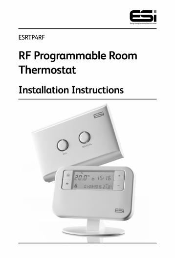
ESRTP4RF
RF Programmable Room Thermostat
Installation Instructions

Thank you for choosing ESi Controls.
All our products are tested in the UK so we are confident this product will reach you in perfect condition and give you many years of service. However, for additional peace of mind, we recommend you register your product online at www.esicontrols.co.uk/warranty for your extended warranty.
2
Installation Instructions1 Technical Specification 1.1 Programmable room thermostat 6 Receiver 6
2 Installation Instructions 2.1 Installation 7 2.2 General Safety 7 2.3 Maintenance 8 2.4 Safety Notice 8 2.5 Fitting the Programmable Room Thermostat 8 2.6 Fitting the Receiver 9 2.7 Commissioning/Configuring 10 2.8 Wiring Diagram (Receiver) 11
3 Technical Settings 3.1 Setting TPI, Delayed & Optimum Start 12 3.2 Setting Sensitivity/Swing and Calibration 13 3.3 Setting the Landlord Service & Time Events 13 3.4 Lockout feature 15 3.5 Setting the Installer Lockout feature 15
Contents
3

4
5
Installation Instructions
6
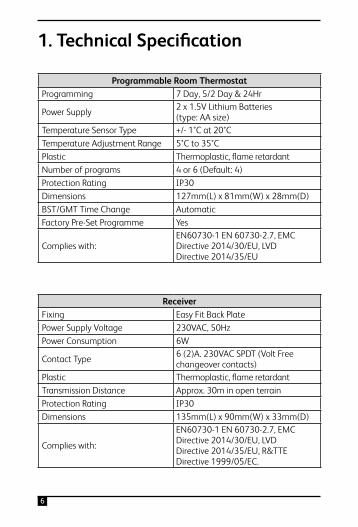
Programmable Room ThermostatProgramming 7 Day, 5/2 Day & 24Hr
Power Supply 2 x 1.5V Lithium Batteries(type: AA size)
Temperature Sensor Type +/- 1°C at 20°CTemperature Adjustment Range 5°C to 35°CPlastic Thermoplastic, flame retardantNumber of programs 4 or 6 (Default: 4)Protection Rating IP30Dimensions 127mm(L) x 81mm(W) x 28mm(D)BST/GMT Time Change AutomaticFactory Pre-Set Programme Yes
Complies with:EN60730-1 EN 60730-2.7, EMCDirective 2014/30/EU, LVDDirective 2014/35/EU
ReceiverFixing Easy Fit Back PlatePower Supply Voltage 230VAC, 50HzPower Consumption 6W
Contact Type 6 (2)A. 230VAC SPDT (Volt Freechangeover contacts)
Plastic Thermoplastic, flame retardantTransmission Distance Approx. 30m in open terrainProtection Rating IP30Dimensions 135mm(L) x 90mm(W) x 33mm(D)
Complies with:
EN60730-1 EN 60730-2.7, EMCDirective 2014/30/EU, LVDDirective 2014/35/EU, R&TTEDirective 1999/05/EC.
1. Technical Specification
7
2. Installation
2.1 Installation Safety InstructionsThe unit must be installed by a suitably qualified person in accordance with the latest IEE Wiring Regulations.
Isolate mains supply before commencing installation. Please read all instructions before proceeding.
Ensure that the fixed wiring connections to the mains supply is via a fuse rated at not more than 6 amps and class ‘A’ switch having a contact separation of a minimum of 3mm in all poles. The recommended cable sizes are 1.0mm sqr or 1.5mm sqr. No earth connection is required as the product is double insulated but ensure continuity of earth throughout the system.
2.2 General Safety InstructionsWhen fitting batteries, do not mix old and new batteries together. Do not use rechargeable batteries.
This product complies with the essential requirements of the following EC Directives:
• Electro-Magnetic Compatibility Directive 2014/30/EU
• Low Voltage Directive 2014/35/EU
• EC Marking Directive 93/68/EEC
• R&TTE Directive 1999/05/EC
8
1.5m
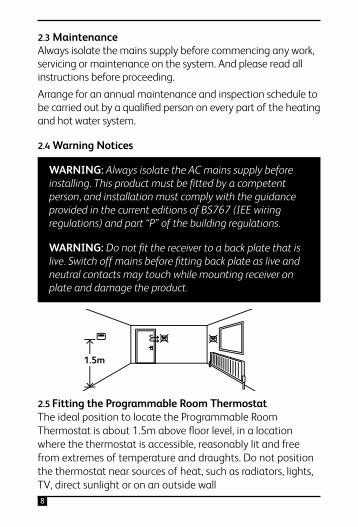
2.4 Warning Notices
WARNING: Always isolate the AC mains supply before installing. This product must be fitted by a competent person, and installation must comply with the guidance provided in the current editions of BS767 (IEE wiring regulations) and part “P” of the building regulations.
WARNING: Do not fit the receiver to a back plate that islive. Switch off mains before fitting back plate as live and neutral contacts may touch while mounting receiver on plate and damage the product.
2.5 Fitting the Programmable Room ThermostatThe ideal position to locate the Programmable Room Thermostat is about 1.5m above floor level, in a location where the thermostat is accessible, reasonably lit and free from extremes of temperature and draughts. Do not position the thermostat near sources of heat, such as radiators, lights, TV, direct sunlight or on an outside wall
2.3 MaintenanceAlways isolate the mains supply before commencing any work, servicing or maintenance on the system. And please read all instructions before proceeding.Arrange for an annual maintenance and inspection schedule to be carried out by a qualified person on every part of the heating and hot water system.
9
Installation 1. Remove the front cover using a flat screwdriver in the
two holes at the top of the programmer and separate from back plate.
2. If required, fix the back plate directly on the wall using suitable wall plugs and screws or mount over existing wall box. Replace the thermostat onto the back plate, securing the bottom of the thermostat first and clicking the thermostat into place. Alternatively, use the stand provided.
3. Insert the 2 x AA batteries provided in the battery compartment on the front of the thermostat, underneath the facia. The Programmable Room Thermostat is now installed and will automatically start to control the room temperature according to the factory pre-set programme as shown in the User Instructions. The display shows the correct time and date which is automatically set together with the actual room temperature.
2.6 Fitting the ReceiverInstallation 1. Loosen the screws on the back-plate and remove from
the Unit.
2. Fix the back-plate, terminals at the top, either direct onto a flat wall using wall plugs and screws or on a flush mounting single conduit box. Route the wires through the back of the wall plate and fit the wires to the wall-plate in accordance with the relevant diagram and in accordance with I.E.E. regulations.
3. Fit the Unit onto back-plate and tighten the screws.
4. Ensure an appropriate fuse is fitted to the circuit before reconnecting to the mains supply.
10
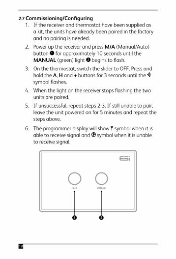
2.7 Commissioning/Configuring 1. If the receiver and thermostat have been supplied as
a kit, the units have already been paired in the factory and no pairing is needed.
2. Power up the receiver and press M/A (Manual/Auto) button 1 for approximately 10 seconds until the MANUAL (green) light 2 begins to flash.
3. On the thermostat, switch the slider to OFF. Press and hold the A, H and + buttons for 3 seconds until the symbol flashes.
4. When the light on the receiver stops flashing the two units are paired.
5. If unsuccessful, repeat steps 2-3. If still unable to pair, leave the unit powered on for 5 minutes and repeat the steps above.
6. The programmer display will show symbol when it is able to receive signal and symbol when it is unable to receive signal.
M/A MANUAL
1 2
11
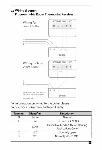
2.8 Wiring diagram Programmable Room Thermostat Receiver
Terminal Identifier DescriptionN Neutral NeutralL Live Live Feed (230V AC)
1 COM Linked Live Feed (230V AC Heating Applications Only)
2 N/O Normally open3 N/C Normally closed (NC)
Wiring for basic 230V boiler
N.B. DO NOT use a link wire on volt free or low voltage boilers
Terminal 2 is SL
LN
For information on wiring to the boiler please contact your boiler manufacturer directly!
N L
N L 1 2 3
RECEIVER BACKPLATE
BOILER
Wiring for combi boiler
LN
For information on wiring to the boiler please contact your boiler manufacturer directly!
BOILER
N L T1 T2
N L 1 2 3
RECEIVER BACKPLATE
For information on wiring to the boiler please contact your boiler manufacturer directly!
12
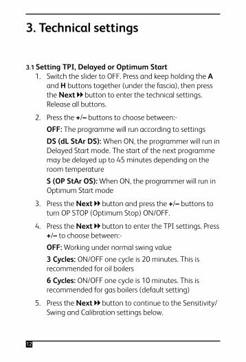
3.1 Setting TPI, Delayed or Optimum Start 1. Switch the slider to OFF. Press and keep holding the A
and H buttons together (under the fascia), then press the Next button to enter the technical settings. Release all buttons.
2. Press the +/– buttons to choose between:-
OFF: The programme will run according to settings
DS (dL StAr DS): When ON, the programmer will run in Delayed Start mode. The start of the next programme may be delayed up to 45 minutes depending on the room temperature
S (OP StAr OS): When ON, the programmer will run in Optimum Start mode
3. Press the Next button and press the +/– buttons to turn OP STOP (Optimum Stop) ON/OFF.
4. Press the Next button to enter the TPI settings. Press +/– to choose between:-
OFF: Working under normal swing value
3 Cycles: ON/OFF one cycle is 20 minutes. This is recommended for oil boilers
6 Cycles: ON/OFF one cycle is 10 minutes. This is recommended for gas boilers (default setting)
5. Press the Next button to continue to the Sensitivity/Swing and Calibration settings below.
3. Technical settings
13
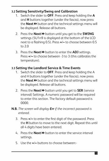
3.2 Setting Sensitivity/Swing and Calibration 1. Switch the slider to OFF. Press and keep holding the A
and H buttons together (under the fascia), now press the Next button and the technical settings menu will be displayed. Release all buttons.
2. Press the Next button until you get to the SWING settings (5U1n9 is displayed at the bottom of the LCD next to a flashing 0.5). Press +/– to choose between 0.5 to 2.0
3. Press the Next button to enter the ADJ settings. Press +/– to choose between -3 to 3 (this calibrates the temperature).
3.3 Setting the Landlord Service & Time Events 1. Switch the slider to OFF. Press and keep holding the A
and H buttons together (under the fascia), now press the Next button and the technical settings menu will be displayed. Release all buttons.
2. Press the Next button until you get to SER (service interval) Settings. A numeric password will be required to enter this section. The factory default password is 0000.
N.B. The screen will display Err if the incorrect password is entered.
3. Press +/– to enter the first digit of the password. Press the H button to move to the next digit. Repeat this until all 4 digits have been entered.
4. Press the Next button to enter the service interval settings.
5. Use the +/– buttons to choose between:-
14
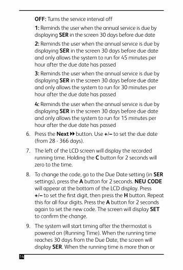
OFF: Turns the service interval off
1: Reminds the user when the annual service is due by displaying SER in the screen 30 days before due date
2: Reminds the user when the annual service is due by displaying SER in the screen 30 days before due date and only allows the system to run for 45 minutes per hour after the due date has passed
3: Reminds the user when the annual service is due by displaying SER in the screen 30 days before due date and only allows the system to run for 30 minutes per hour after the due date has passed
4: Reminds the user when the annual service is due by displaying SER in the screen 30 days before due date and only allows the system to run for 15 minutes per hour after the due date has passed
6. Press the Next button. Use +/– to set the due date (from 28 - 366 days).
7. The left of the LCD screen will display the recorded running time. Holding the C button for 2 seconds will zero to the time.
8. To change the code, go to the Due Date setting (in SER settings), press the A button for 2 seconds. NEU CODE will appear at the bottom of the LCD display. Press +/– to set the first digit, then press the H button. Repeat this for all four digits. Press the A button for 2 seconds again to set the new code. The screen will display SET to confirm the change.
9. The system will start timing after the thermostat is powered on (Running Time). When the running time reaches 30 days from the Due Date, the screen will display SER. When the running time is more than or
15
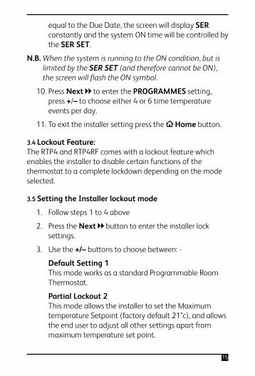
equal to the Due Date, the screen will display SER constantly and the system ON time will be controlled by the SER SET.
N.B. When the system is running to the ON condition, but is limited by the SER SET (and therefore cannot be ON), the screen will flash the ON symbol.
10. Press Next to enter the PROGRAMMES setting, press +/– to choose either 4 or 6 time temperature events per day.
11. To exit the installer setting press the Home button.
3.4 Lockout Feature: The RTP4 and RTP4RF comes with a lockout feature which enables the installer to disable certain functions of the thermostat to a complete lockdown depending on the mode selected.
3.5 Setting the Installer lockout mode
1. Follow steps 1 to 4 above
2. Press the Next button to enter the installer lock settings.
3. Use the +/– buttons to choose between: -
Default Setting 1 This mode works as a standard Programmable Room Thermostat.
Partial Lockout 2 This mode allows the installer to set the Maximum temperature Setpoint (factory default 21°c), and allows the end user to adjust all other settings apart from maximum temperature set point.
16
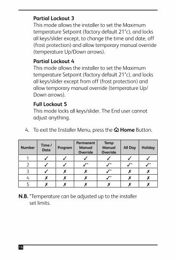
Partial Lockout 3 This mode allows the installer to set the Maximum temperature Setpoint (factory default 21°c), and locks all keys/slider except, to change the time and date, off (frost protection) and allow temporary manual override (temperature Up/Down arrows).
Partial Lockout 4 This mode allows the installer to set the Maximum temperature Setpoint (factory default 21°c), and locks all keys/slider except from off (frost protection) and allow temporary manual override (temperature Up/Down arrows).
Full Lockout 5 This mode locks all keys/slider. The End user cannot adjust anything.
4. To exit the Installer Menu, press the Home Button.
N.B. *Temperature can be adjusted up to the installer set limits.
Number Time / Date Program
Permanent Manual Override
Temp Manual Override
All Day Holiday
1 ✓ ✓ ✓ ✓ ✓ ✓
2 ✓ ✓ ✓* ✓* ✓* ✓*3 ✓ ✗ ✗ ✓* ✗ ✗
4 ✗ ✗ ✗ ✓* ✗ ✗
5 ✗ ✗ ✗ ✗ ✗ ✗

17
18
WARNING: Interference with sealed parts renders the guarantee void.
In the interests of continuous product improvement we reserve the right to alter designs, specifications and materials without prior notice and cannot accept liability for errors.

19
We are continuously developing our products to bring you the very latest in energy saving technology and simplicity. However, should you have any questions setting up your controls please email us at [email protected].

Version 6.10.1