Embed Size (px)
Citation preview
Essential tools for Clinical Cardiovascular MRI
Raja Muthupillai, PhD,DABMP, DABRDirector of Imaging Research
Department of Diagnostic and Interventional Radiology
Baylor St Luke’s Medical Center,Houston, TX 77030

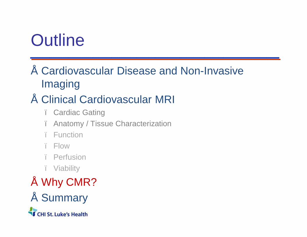
Outline
• Cardiovascular Disease and Non-Invasive Imaging
• Clinical Cardiovascular MRI– Cardiac Gating– Anatomy– Function– Flow– Perfusion– Viability
• Why CMR?• Summary

Cost of Heart Disease : Lives
610,000 deaths per year;1 in 4 deaths; ~50% due to CAD ;109 Billion USD
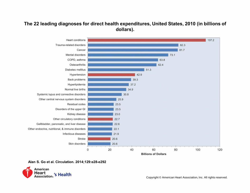
The 22 leading diagnoses for direct health expenditures, United States, 2010 (in billions of dollars).
Alan S. Go et al. Circulation. 2014;129:e28-e292
Copyright © American Heart Association, Inc. All rights reserved.

Percentage breakdown of deaths attributable to
cardiovascular disease (United States: 2010).
Alan S. Go et al. Circulation. 2014;129:e28-e292Heart Disease and Stroke Statistics—2014 Update
Copyright © American Heart Association, Inc. All rights reserved.
What we need to see?
• Congenital Anomalies• Coronaries• Coronary Blood Flow
• Perfusion• Myocardium
• Infections• Viability• Infiltrative Processes
• Cardiac vessels• Valves• Functional Information• …

Cardiac Imaging Modalities: Echo
Echocardiography
Echocardiography
Strengths:
Real-time, InexpensiveWall motionValvular functionBlood flow velocity
Limitations:
Need for acoustic windowsLimited coverageSingle contrast mechanism
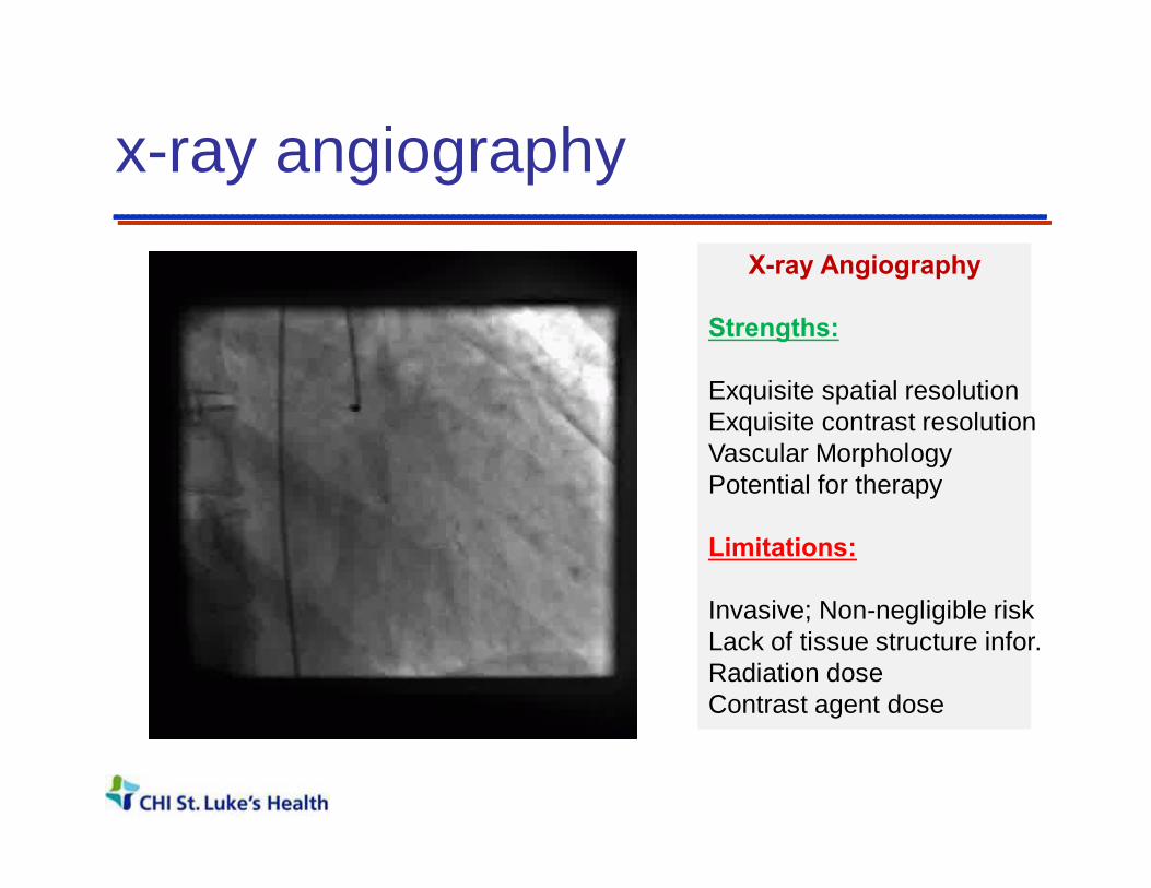
x-ray angiographyX-ray Angiography
Strengths:
Exquisite spatial resolutionExquisite contrast resolutionVascular MorphologyPotential for therapy
Limitations:
Invasive; Non-negligible riskLack of tissue structure infor.Radiation doseContrast agent dose

x-ray computed tomographyX-ray CT
Strengths:
High Spatial resolutionExquisite contrast resolutionCardiac AnatomyCalcificationsSurgical PlanningFast
Limitations:Cardiac FunctionValve FunctionRadiation doseContrast agent dose

Nuclear ScintigraphyNuclear Scintigraphy
Strengths:
Exquisite sensitivityFunctional Imaging methodPerfusion and Viability
Limitations:
Modest Spatial ResolutionLack of tissue structure infor.Radiation dose
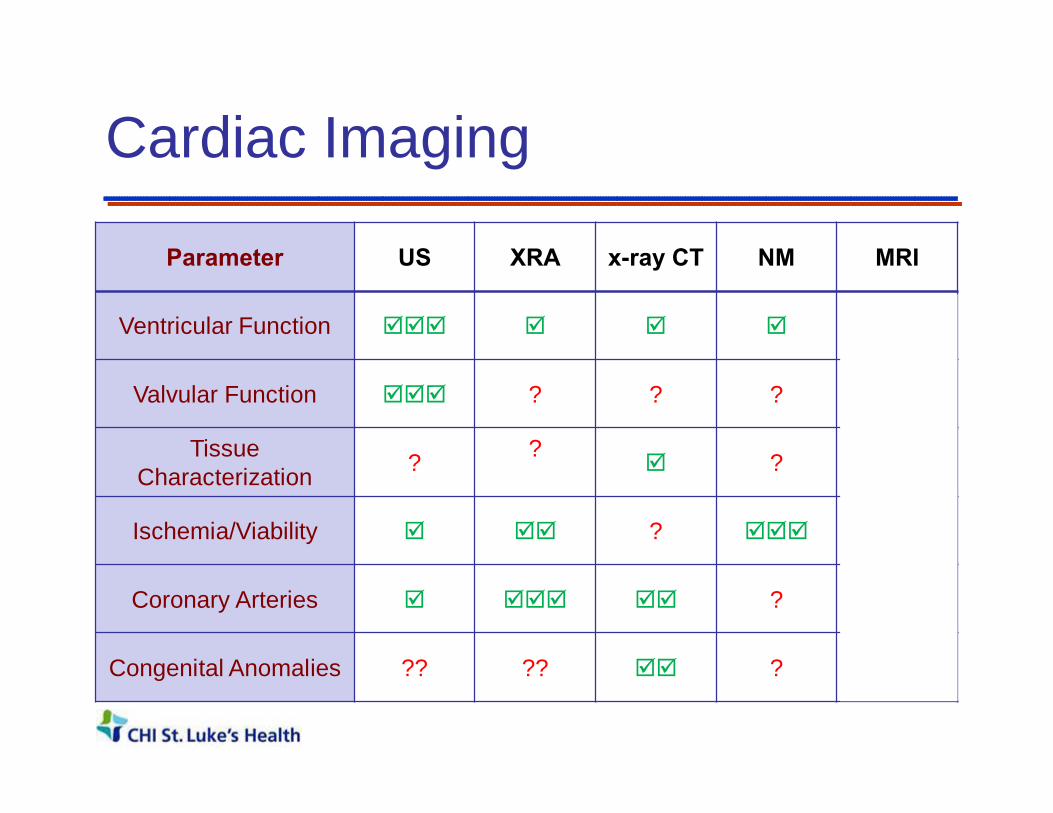
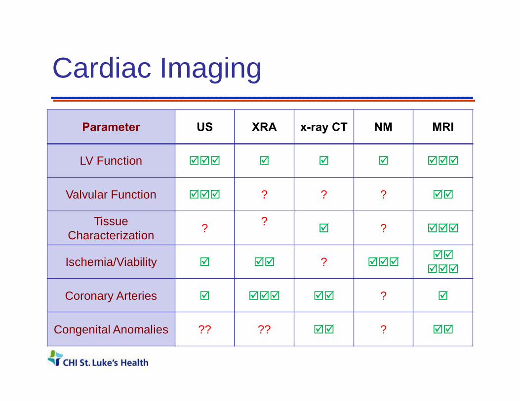
Cardiac Imaging
Parameter US XRA x-ray CT NM MRI
Ventricular Function þþþ þ þ þ þþþ
Valvular Function þþþ ? ? ? þþ
Tissue Characterization ? ?
þ ? þþþ
Ischemia/Viability þ þþ ? þþþ þþ
Coronary Arteries þ þþþ þþ ? þ
Congenital Anomalies ?? ?? þþ ? þþ
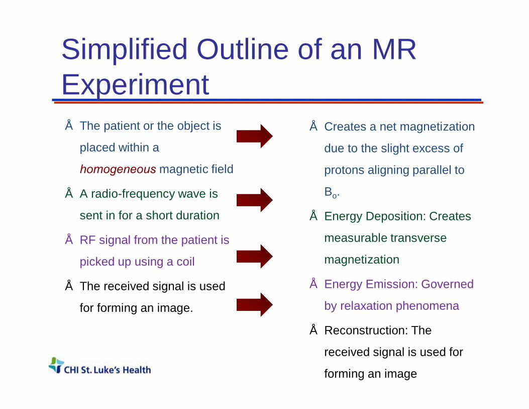
Simplified Outline of an MR Experiment• The patient or the object is
placed within a
homogeneous magnetic field
• A radio-frequency wave is
sent in for a short duration
• RF signal from the patient is
picked up using a coil
• The received signal is used
for forming an image.
• Creates a net magnetization
due to the slight excess of
protons aligning parallel to
Bo.
• Energy Deposition: Creates
measurable transverse
magnetization
• Energy Emission: Governed
by relaxation phenomena
• Reconstruction: The
received signal is used for
forming an image

• Simple 2DFT Imaging:
Time between phase encoding steps : TR(~ of 100s of ms ; T1 relaxation time)
Time from excitation to Readout : TE(~ of 10s of ms ; T2 relaxation time)
Repeat the experiment over several TR( Allows for longitudinal relaxation between
phase encoding steps)
Conventional 2DFT MR imaging
kx
ky

Assumption: Consistency of Data

Outline
• Cardiovascular Disease and Non-Invasive Imaging
• Clinical Cardiovascular MRI– Cardiac Gating– Anatomy– Function– Flow– Perfusion– Viability
• Why CMR?• Summary
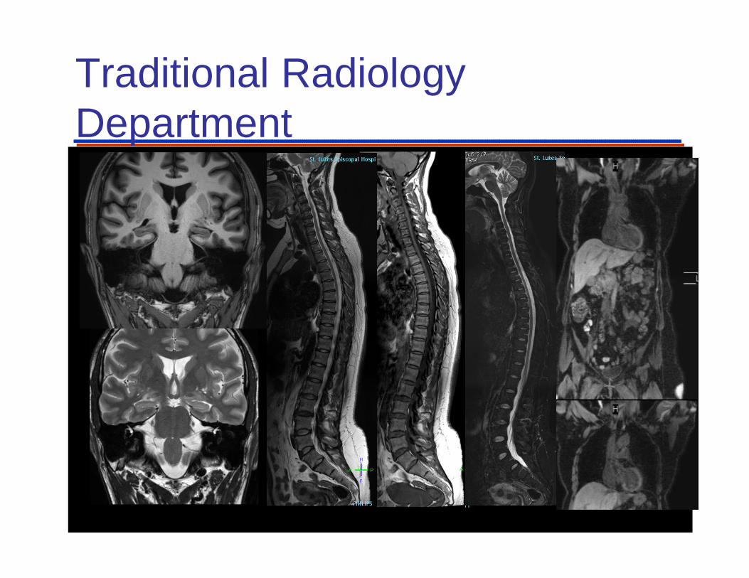
Traditional Radiology Department

1. Cardiac Synchronization
Heart moves substantially with
Cardiac Pulsation ( ~ 1 Hz)
and
Respiration (0.05 Hz)
T1 relaxation rates ~ 1 Hz
Time scale of MR is on theorder of seconds to minutes
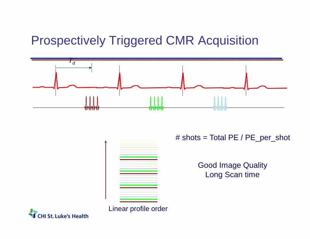
Prospectively Triggered CMR Acquisition
# shots = Total PE / PE_per_shot
Td
Good Image QualityLong Scan time
Linear profile order

ECG Synchronization: Gating
Gw Gw Gw
• Maintains Steady State - Continuous RF excitation• No flashing artifact• Single or Multi-phase images• Low SNR / Time consuming (often used in FQ studies)
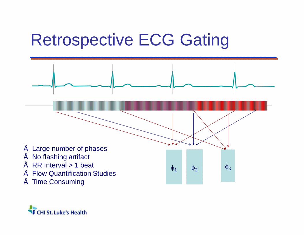
Retrospective ECG Gating
• Large number of phases• No flashing artifact• RR Interval > 1 beat• Flow Quantification Studies• Time Consuming
φ1 φ2 φ3

Outline
• Cardiovascular Disease and Non-Invasive Imaging
• Clinical Cardiovascular MRI– Cardiac Gating– Anatomy / Tissue Characterization– Function– Flow– Perfusion– Viability
• Why CMR?• Summary
(2) Myocardial Morphology: Black Blood Imaging Techniques• Blood Appears Black / Dark• High Anatomic Detail• Typically Spin Echo Methods
– Spin Echo– Turbo Spin Echo (TSE)– Inversion Recovery TSE
• Diastolic Images (Diastole)• Cardiac Triggered Sequences• Rely on blood flow (Outflow)
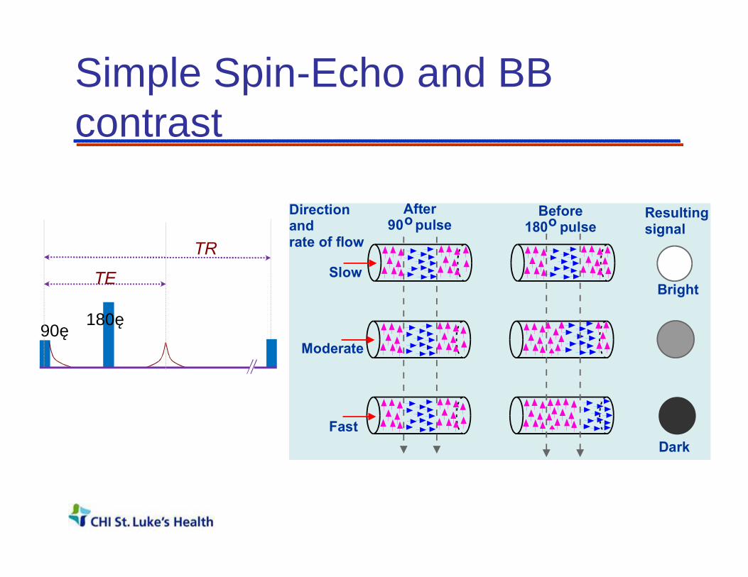
Simple Spin-Echo and BB contrast
Directionandrate of flow
Resultingsignal
Bright
Dark
Slow
Moderate
Fast
Before180 pulseo
After90 pulseo
90˚180˚
TR
TE
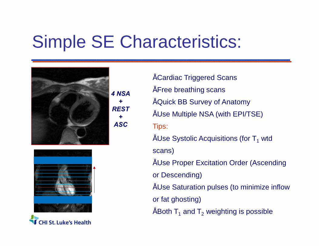
Simple SE Characteristics:
4 NSA+
REST+
ASC
• Cardiac Triggered Scans
• Free breathing scans
• Quick BB Survey of Anatomy
• Use Multiple NSA (with EPI/TSE)
Tips:
• Use Systolic Acquisitions (for T1 wtd
scans)
• Use Proper Excitation Order (Ascending
or Descending)
• Use Saturation pulses (to minimize inflow
or fat ghosting)
• Both T1 and T2 weighting is possible
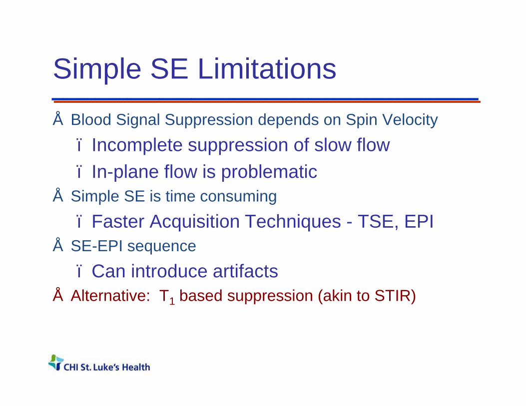
Simple SE Limitations• Blood Signal Suppression depends on Spin Velocity
– Incomplete suppression of slow flow– In-plane flow is problematic
• Simple SE is time consuming– Faster Acquisition Techniques - TSE, EPI
• SE-EPI sequence– Can introduce artifacts
• Alternative: T1 based suppression (akin to STIR)

Double Inversion BB Imaging MyocardiumBlood
• The first non-selective inversion inverts everything
• The second selective inversion pulse re-inverts the signal within slice
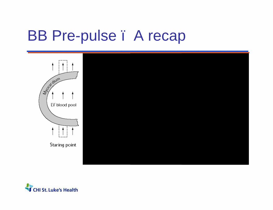
BB Pre-pulse – A recap
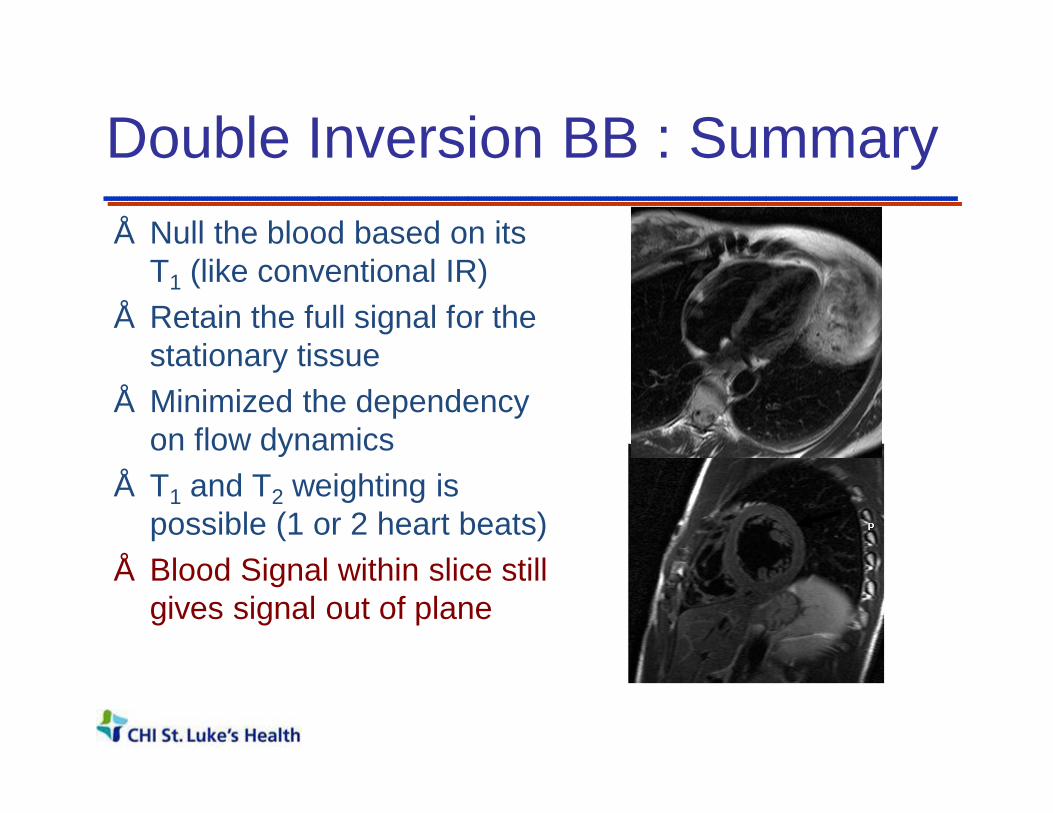
Double Inversion BB : Summary • Null the blood based on its
T1 (like conventional IR)• Retain the full signal for the
stationary tissue• Minimized the dependency
on flow dynamics• T1 and T2 weighting is
possible (1 or 2 heart beats)• Blood Signal within slice still
gives signal out of plane

Edema “Weighted” Imaging Vs T2 mapping in AMI
Acute Myocardial Infarction ModelEvaluation of stem cell therapy
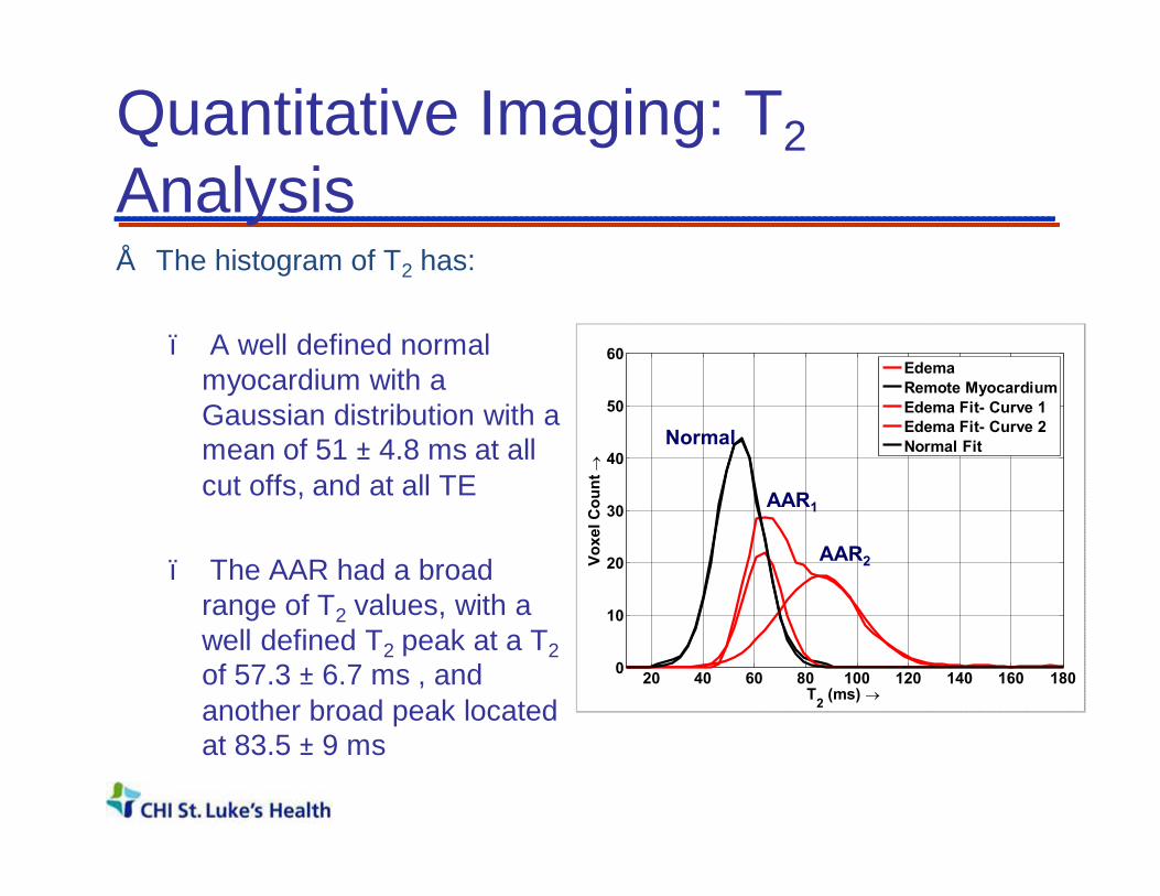
Quantitative Imaging: T2Analysis• The histogram of T2 has:
– A well defined normal myocardium with a Gaussian distribution with a mean of 51 ± 4.8 ms at all cut offs, and at all TE
– The AAR had a broad range of T2 values, with a well defined T2 peak at a T2of 57.3 ± 6.7 ms , and another broad peak located at 83.5 ± 9 ms
20 40 60 80 100 120 140 160 1800
10
20
30
40
50
60
T2 (ms) →
Voxe
l Cou
nt →
EdemaRemote MyocardiumEdema Fit- Curve 1Edema Fit- Curve 2Normal FitNormal
AAR2
AAR1

Cardiac Mass - Tissue Characterization:Lipomatous Hypertrophy of the Interatrial Septum/Right Atrium
Dual-IR Fast T2 +Fat Supp. Post Gd. + Fat Supp.

Fat Suppression - Triple IR
Double IR Triple IR
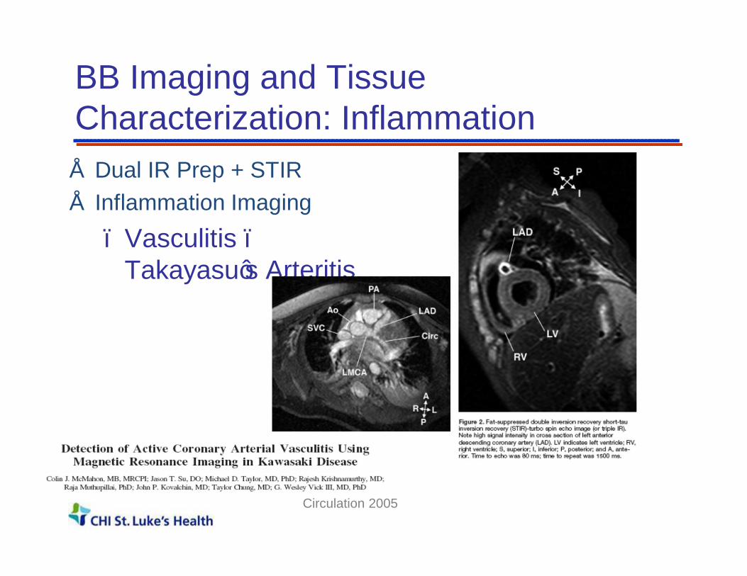
BB Imaging and Tissue Characterization: Inflammation• Dual IR Prep + STIR• Inflammation Imaging
– Vasculitis –Takayasu’s Arteritis
Circulation 2005

CMR Morphologic Assessment• Size/Shape of heart and vessels
• Freely angulated field of view; Large field of view
• Soft tissue contrast:– Tumor Characterization– Inflammation, Edema– Quantitative imaging

Outline
• Cardiovascular Disease and Non-Invasive Imaging
• Clinical Cardiovascular MRI– Cardiac Gating– Anatomy / Tissue Characterization– Function– Flow– Perfusion– Viability
• Why CMR?• Summary

Gradient Echo Basics
• After one RF pulse, FID• After two or more RF pulses, we
get an FID + Spin Echo • When the transverse
magnetization is spoiled or destroyed, we get T1-FFE or spoiled gradient echo
• When it is preserved carefully we get TrueFISP, or bFFE.
• The preservation is done by carefully balancing the gradient areas along all axis to be zero for each TR
α-pulse
T2* (intra-voxel)
Echo
TE
Gradient0
T2*
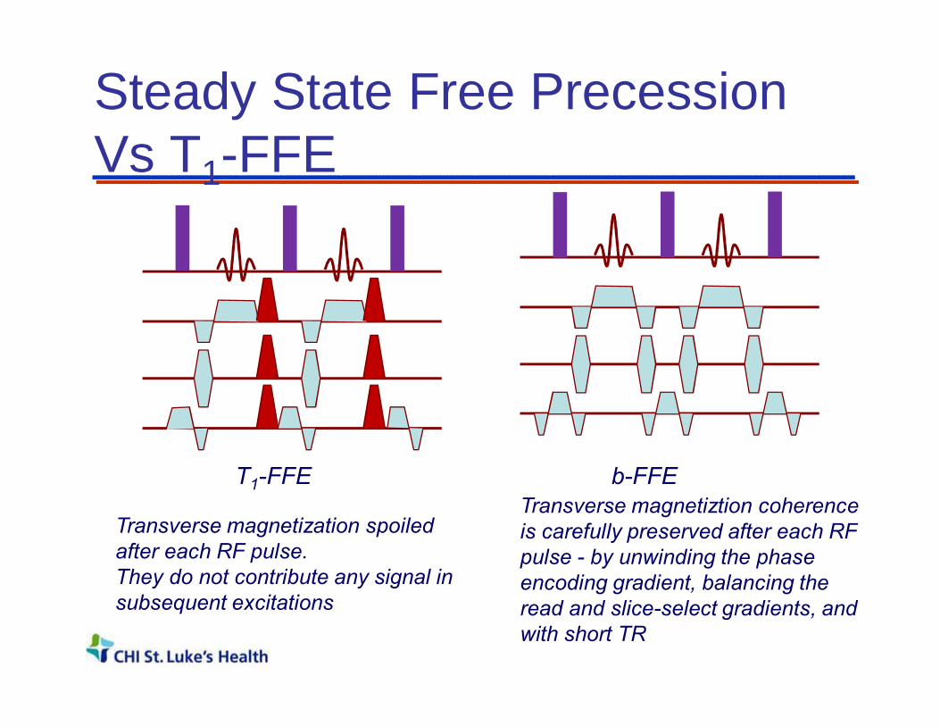
Steady State Free Precession Vs T1-FFE
T1-FFE
Transverse magnetization spoiled after each RF pulse.They do not contribute any signal in subsequent excitations
b-FFETransverse magnetiztion coherence is carefully preserved after each RF pulse - by unwinding the phase encoding gradient, balancing the read and slice-select gradients, and with short TR
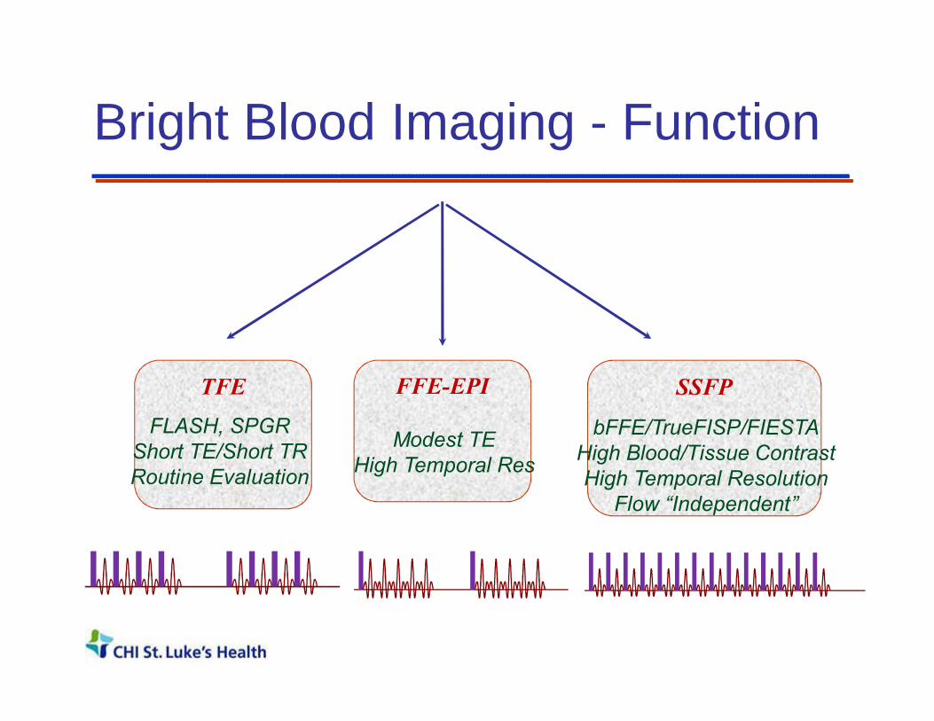
Bright Blood Imaging - Function
TFE SSFPFFE-EPI
FLASH, SPGRShort TE/Short TRRoutine Evaluation
Modest TEHigh Temporal Res
bFFE/TrueFISP/FIESTAHigh Blood/Tissue ContrastHigh Temporal Resolution
Flow “Independent”
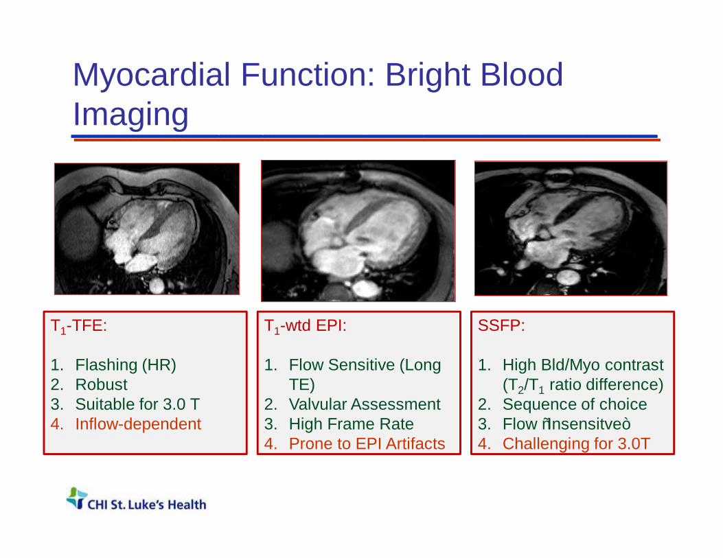
Myocardial Function: Bright Blood Imaging
T1-TFE:
1. Flashing (HR)2. Robust3. Suitable for 3.0 T4. Inflow-dependent
T1-wtd EPI:
1. Flow Sensitive (Long TE)
2. Valvular Assessment3. High Frame Rate4. Prone to EPI Artifacts
SSFP:
1. High Bld/Myo contrast(T2/T1 ratio difference)
2. Sequence of choice3. Flow “Insensitve” 4. Challenging for 3.0T

SSFP – Field Homogeneity Requirements
TR=3.3 msec TR=3.6 msec
TR=4.0 msec TR=5.0 msec
• SNR independent of TR• Shortest possible TR• Requires high field
homogeneity• Autoshim /Use shim
volumes if necessary!• Typical TR <= 4 msec

LV function Evaluation
End Diastolic Volume (EDV)End Systolic Volume (ESV)Stroke Volume (SV)Ejection Fraction (EF (%))Cardiac Mass
Regional Wall motion information

Why is this important?• CMR is highly reproducible; • Devoid of geometric assumptions• Both RV and LV volumes
To detectn req.
forEcho
n req. forMR
10 ml change in EDV 66 13
10 ml change inESV 82 12
10 gm change in LV mass 194 20
3% change in EF 73 7
In heart failure patients; power = 0.9p < 0.05
Outline
• Cardiovascular Disease and Non-Invasive Imaging
• Clinical Cardiovascular MRI– Cardiac Gating– Anatomy / Tissue Characterization– Function– Flow– Perfusion– Viability
• Why CMR?• Summary

Myocardial Function
Myocardial Ischemia – Overview
MechanicalDysfunction
ReversibleInjury
IrreversibleInjury
Normal Resting Mechanical Function
Stunning andHibernation
Is it ischemic? Stress Test?

Some Definitions
Ischemia: Impaired blood supply; inducible defect with stress
Stunning: Transient Mechanical Dysfunction due to acute ischemic insult
Hibernation: Adaptation to chronic ischemia via down-regulation.
Cell death: Loss of cell membrane integrity –irreversible injury either via apoptosis or necrosis.

0 50 1000
1
2
3
4
% Lumen narrowing ->
Rest
Stress
Myocardial Blood Flow Reserve
Stress Perfusion
Viability
QualitativeAnalysis

MR Perfusion Measurement• Changes in T1 caused by
Gd-DTPA during first pass
indicate microvascular flow.
• At low concentrations, T1
changes are linearly
related to concentration of
Gd-DTPA.
• The SI in a T1 weighted
sequence can therefore be
linked to the concentration
of Gd-DTPA.

Perfusion Analysis :
MR signal
timeTTPT0
S0
Myocardial signal
Bloodpool
LVMU
MU
LVS0
RMU = x 100%
MUS0
LVMULVS0
• Mean upslope• Relative mean
upslope• Time to arrival• Time to peak• Peak enhancement• Relative peak
enhancement

Myocellular matrix: Before Injury
Distribution volume For Extracellular agent (0.3)
Intact Myocytes

Irreversible Injury : Distribution volume (Vd) for Gd goes up
Distribution volume forExtracellular agent
Intact Myocytes
Injured Myocytes

Myocellular Injury and Vd
• Loss of cell membrane integrity
– Increased Distribution volume for Gadolinium• Chronic Case
– Increased deposition of fibrous tissue – Collagen matrix
– Increased distribution volume for an extracellular contrast medium
• Differential Accumulation of Extravascular agent

Delayed-Enhancement MRI

Myocardial Viability MRI• High Contrast
Resolution
• Transmurality of Infarction
• Well validated
• Clinically Simple to Use
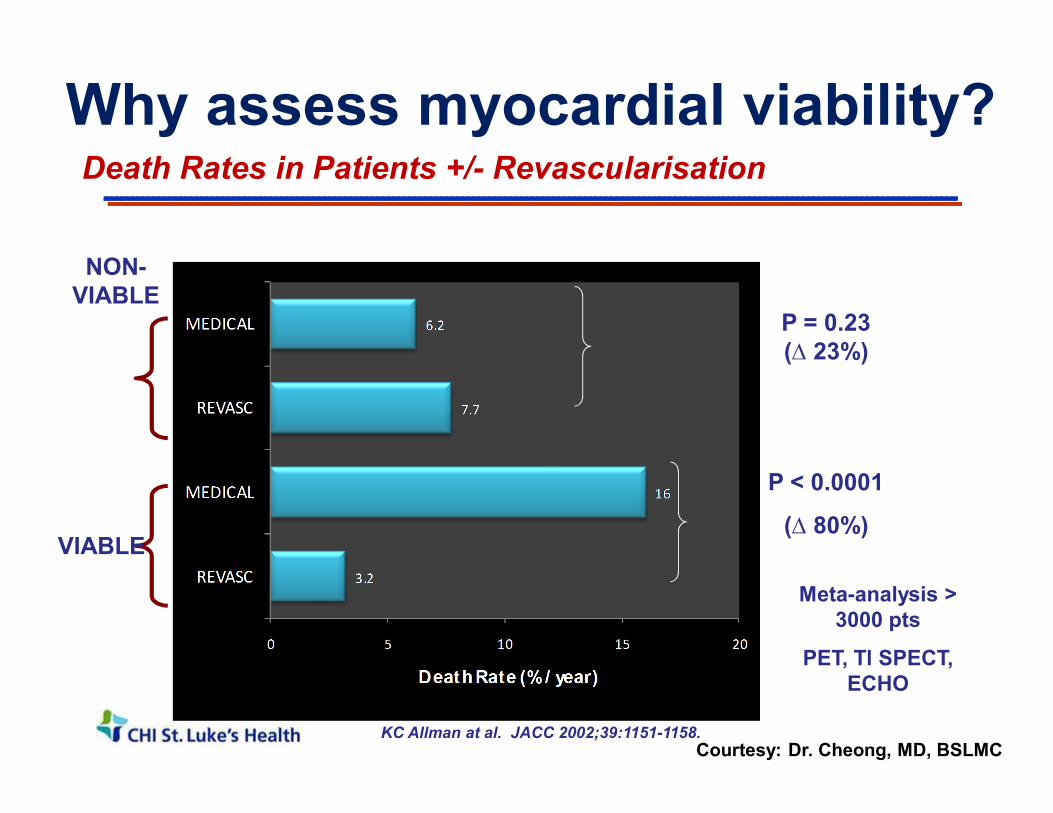
Death Rates in Patients +/- Revascularisation
VIABLE
NON-VIABLE
P = 0.23 (∆ 23%)
P < 0.0001
(∆ 80%)
KC Allman at al. JACC 2002;39:1151-1158.
Meta-analysis > 3000 pts
PET, Tl SPECT, ECHO
Why assess myocardial viability?
Courtesy: Dr. Cheong, MD, BSLMC

SLEH MV Trial : Segmental Wall Motion
Accepted for publication, JACC 2013
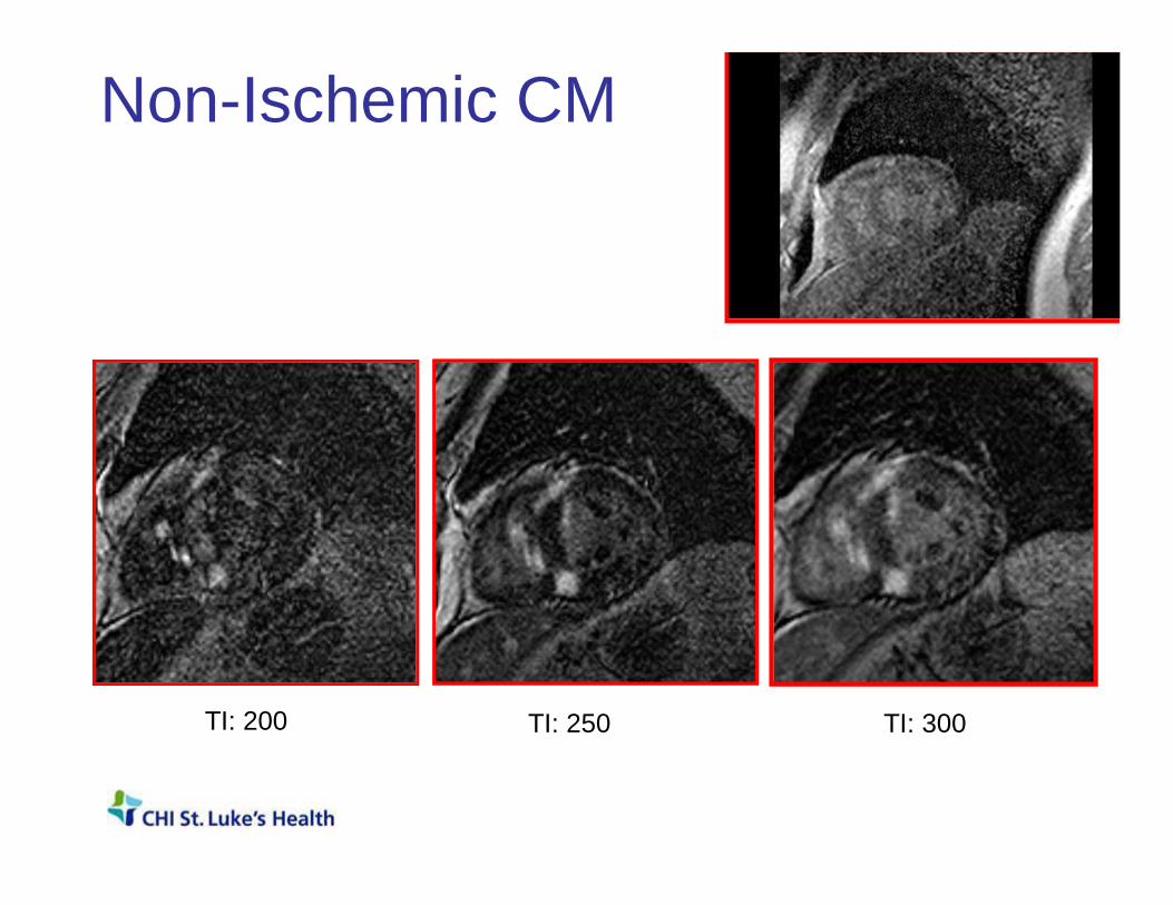
Non-Ischemic CM
TI: 250TI: 200 TI: 300
CMR and Viability• Simple technique to use
– IV line and MR contrast• High contrast resolution• Transmurality of Infarction
– Guides clinical decision making• Ischemic Cardiomyopathy
– Acute and Chronic MI• Non-ischemic cardiomyopathy
– Comprehensive Evaluation (T2, T1, T1ρ etc.)
Outline
• Cardiovascular Disease and Non-Invasive Imaging
• Clinical Cardiovascular MRI– Cardiac Gating– Anatomy / Tissue Characterization– Function– Flow– Perfusion– Viability
• Why CMR?• Summary
Cardiac Imaging
Parameter US XRA x-ray CT NM MRI
LV Function þþþ þ þ þ þþþ
Valvular Function þþþ ? ? ? þþ
Tissue Characterization ? ?
þ ? þþþ
Ischemia/Viability þ þþ ? þþþþþþþþ
Coronary Arteries þ þþþ þþ ? þ
Congenital Anomalies ?? ?? þþ ? þþ
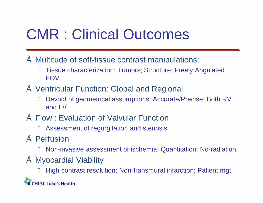
CMR : Clinical Outcomes• Multitude of soft-tissue contrast manipulations:
– Tissue characterization; Tumors; Structure; Freely Angulated FOV
• Ventricular Function: Global and Regional– Devoid of geometrical assumptions; Accurate/Precise; Both RV
and LV
• Flow : Evaluation of Valvular Function– Assessment of regurgitation and stenosis
• Perfusion– Non-invasive assessment of ischemia; Quantitation; No-radiation
• Myocardial Viability– High contrast resolution; Non-transmural infarction; Patient mgt.

CMR: Impediments• Cumbersome technology; Time consuming
• Not suitable for claustrophobic patients
• Not suitable (at the moment) for patients with pacemakers
• Requires Expertise : Technologist / Clinician / Physics
• Radiology / Cardiology Practice Cultures

Thank you!


Phase contrast MRA: Principles
Directionof nuclearmagneticmoment
Direction of appliedmagnetic field
B0
oB αω
Precessional Frequency is proportional to field gradient.
t
φ
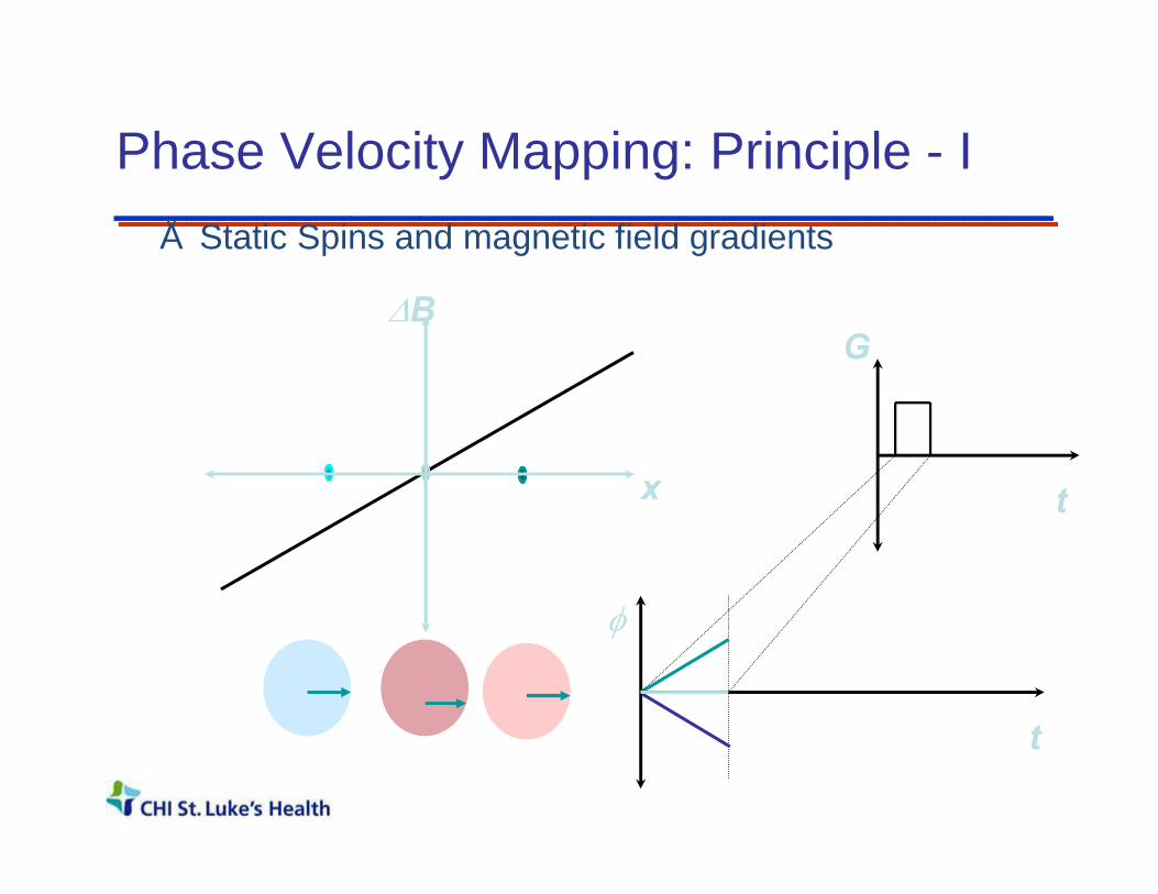
Phase Velocity Mapping: Principle - I• Static Spins and magnetic field gradients
x
∆BG
t

Phase Velocity Mapping: Principle - 2• Static Spins and magnetic field gradients
x
G∆B
t
t
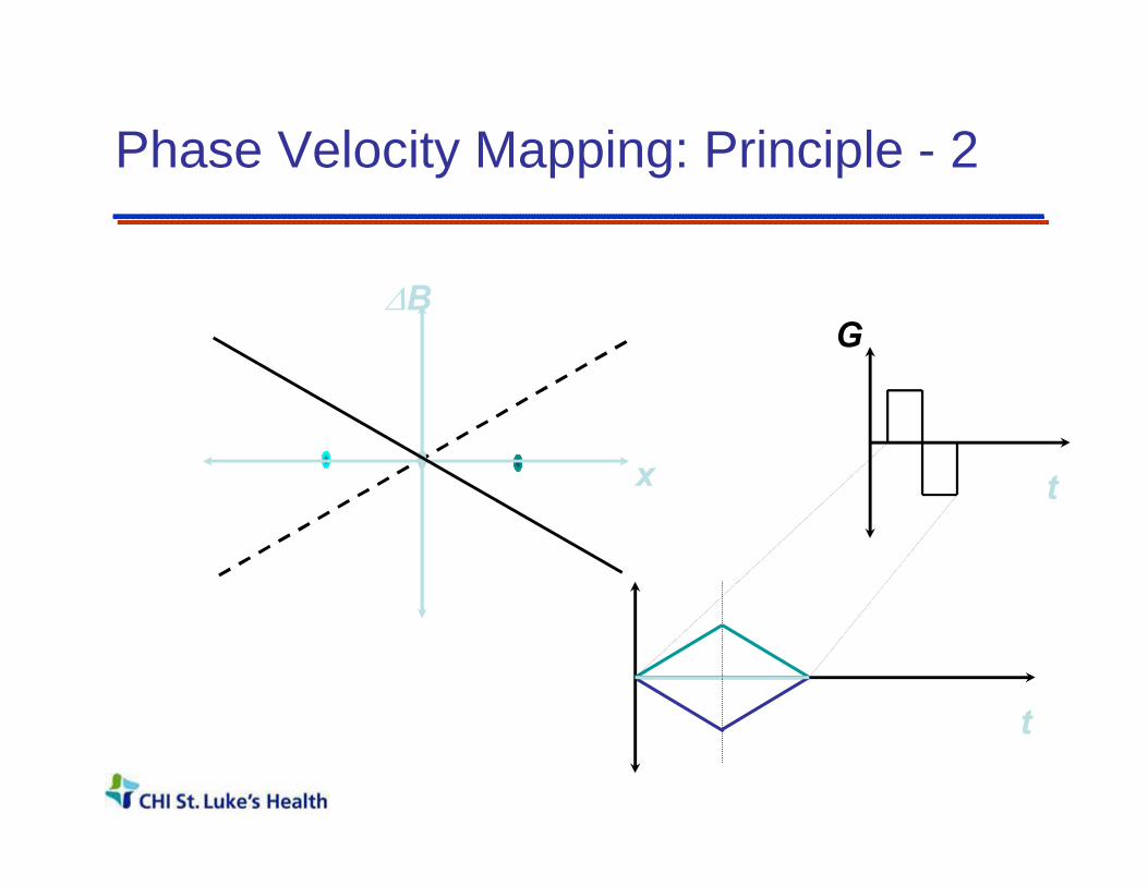
Phase Velocity Mapping: Principle - 2
x
G∆B
t
t

Static spins do not accrue phase in the presence of bipolar gradients (or any other gradient with a zero net area)!

Phase Velocity Mapping: Principle - 3
x
G∆B
t
t
t1 t2x1t0
t1
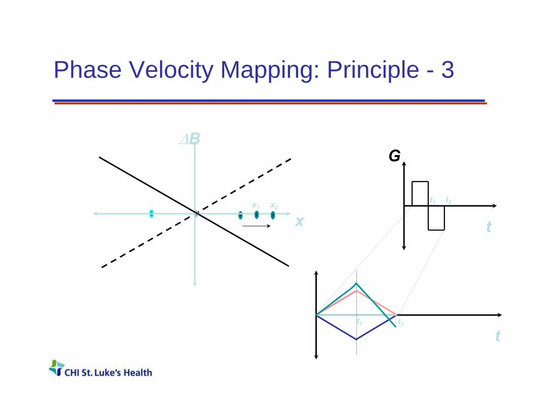
Phase Velocity Mapping: Principle - 3
x
G∆B
t
t
t1 t2x1 x2
t1 t2
Spins moving in the direction of a bi-polar gradient do accumulate a net phase shift.

Concept of Velocity Aliasing0 cm/s
180 cm/s
-45 cm/s +45 cm/s
-90 cm/s +90 cm/s
-135 cm/s +135 cm/s
+210 cm/sOr
- 150 cm/s?
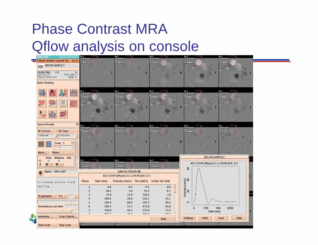
Phase Contrast MRA Qflow analysis on console

Phase Contrast : Key Points• Amplitude of Velocity
(Speed)
• Direction of Velocity (Vector)
• Strength of Velocity Encoding : (Venc)
• Shape of flow wave form
MR Angiography, Peak Velocity, Pressure gradient
Regurgitation, Flow shunts, etc.
Aliasing, Visualization of arteries/veins
Wall-shear stress; Systemic Physiology

Functional MRI for pre-surgical planning
Foot Movement Visual System
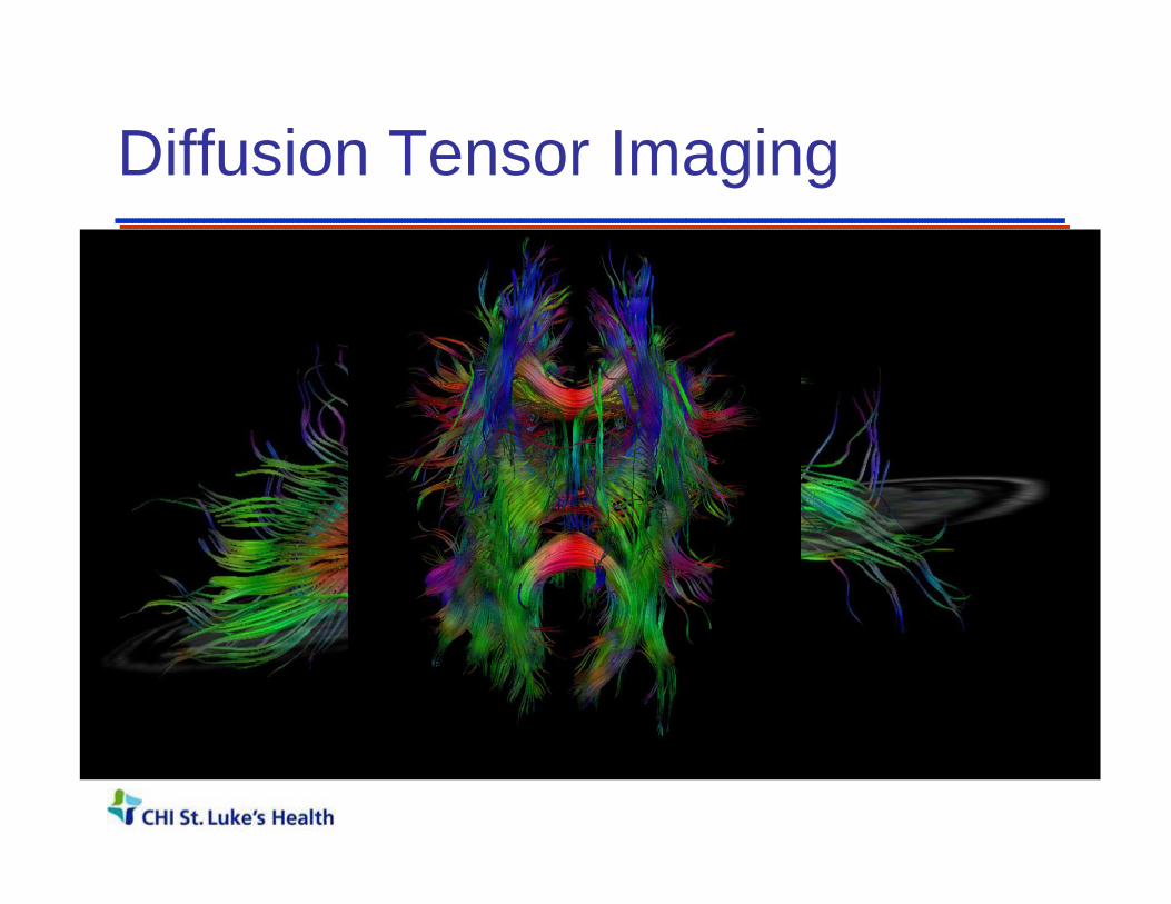
Diffusion Tensor Imaging
Thank you!