Embed Size (px)
Citation preview
A,
ESSO LABORATO.RIBIS5 T A NDA RD O,1IL DB HV ItLOP M BNT 0 OM PAN Y
PROCES I1 VISION
a'F
1ta A r t N -7 !1 OAJ S E
,~~~ ~ A,, . N"- DoY~
PROGRESS ROPORT
..... _ _ t ON
STUDY OF COMBUSTORS
-FOR SUPERSONIC RAM JET
(ODS PROJECT)
FOR PERIOD NOVEMBER 1,1945 -JANUARY 31', 1946
THIS DOCUMENT CONTAINS INFORMATION AFFECTINGTHE NATIONAL DEFENSE OF THE UNITED STATESWITHIN THE MEANING OF THE ESPIONAGE ACT. 50U. 5.,C., 31 AND, *,, ITS TRANSMISSION OR THEREVELATION OF ITS CONTENTS IN ANY MANNER TOAM IIMMITwrnr ) 09 SON IS FROHIBITtD BY LAW
a " .7: - .
... ...... : JAN 1 97 1IllREPORT PDN.- 4136 DISTRISUTION O t-HiSFEBRUARY 10, 1946 DOCUMENT IS UNLIMITED L1LU
/
]DISCLAIMERl NOTICE
COW °
THIS DOCUMENT IS BEST
QUALITY AVAILABLE. THE COPY
FURNISHED TO DTIC CONTAINED
A SIGNIFICANT NUMBER OF
PAGES WHICH DO NOT
REPRODUCE LEGIBLY.
E SSO0 L ABO0RA TO0R IE S
STANDARD OIL DEVELOPMENT COMPANY
PROCESS DIVISION
PROGRESS REPORT
ON
STUDY OF COMBUSTORS FOR SUPERSONIC RAM-JET(ODS PROJECT)
FOR PERIOD NOVEMBER 1, 194f5 -JANUARY 31, 194f6
REPORT BY: REPORT PDN-4i136
k'r.LONWLLL~'DATE: FEBRUARY 10, 194f6
~4~r.fA.~-SOD PROJECT: 31888~%.P. EAMES CONTRACT NORD-9233__ __ __ (BUMBLEBEE PROJECT)
R'. L. YAHNKEJ
IDISTRI13UT1O IMI114Dpocis .ENT
TABLE OF CONTENTS
Page No.
SUMMARY. . . . . . . . , . . . . , o . . . . 1
INTRODUCTION . . .. . . . . . . . 9 . . . . . 2
FACILITIES . . . . . . . . . . . . . . . . . . 2
EXPERIMENT AL WORK. . . . . . . . . . . . . . . . 8
1. Pressure and Ignition Studies . . . . . . 8
2. Burner Performance . . . * . . . . o o * 14
3. Drag of the Burner Interior. . . , . . . 20
FUTURE PROGRAM ........ . ....... 22
APPENDIX . . .. . . . o . . . . . . , . . . . . 23
1. System for Numbering Burners .o..... 23
2. Fuel Inspection. , . ........ . . . 25
3. Detailed Burner Test Data
PDN 4136
SMMARY
The' burner facilities at the Standard Oil Development Comp-Pany at Bayway, New Jersey, became available for test work in Decem-ber, 1945. These facilities essentially consist of a compressor andfurnace capabl.e of supplying up to 13# air/sec. at a maximum tempera-ture of 600 0F., two test cells with a common control room, and a smalloffice building. This equipment is being used to study 6 inch burners,
Previous work on gutter type flame holders carried out atthe Forest Grove Station of Johns Hopkins University demonstratedthat smooth and fairly efficient burning was obtained, but that igni-tion w~s difficult above an air rate of 9 lbs./sec. To burn at Ligherrates it was necessary to ignite at a low air rate and increase theamount of air after combustion had been previously iniated. In thepresent work, investigation of the air pressure at variou. points inthese burners before combustion started showed that immediately down-stream from the flame holder the pressure was below atmospheric andthe velocity above sonic. Since it is known that low pressure makesignition difficult an effort was made to ignite in a zone of higherpressure. This was accomplished by placing two flame holders in seriesand igniting at the uostream flame holder where the pressure was higherdue to the effect of the downstream flame holder. Using this principle,burners capable of spark ignition over a wide range of air/fuel ratiosat an air rate of 11 lbs./sec. have been developed. These burnersdevelop approximately 80% of theoretical thrust at 15:1 air/fuel ratioand 85% of theoretical thrust at 22:1 air/fuel ratio. The air specific
impulse is about 150 lbs. per lbs. of air/sec. at an air/fuel ratio or15:1. The actual thrust under these conditions is about 1000-1100 pounds.
The drag of the atomizing section, the ignition section andthe burner walls, as determined from thrust and pressure measurementsduring burning at 15:1 air/fuel ratio and 11 lbs./sec. of air, amountsto about 11% of the thrust develo-ped or about 4 p.s.i. for one of theburners.
While a spark, tracer 'or some other source of. ignition isnecessary to initiate burning, maintenance of combustion does notdepend on these ignition sources, and burning, once started, will con-
UtSue W.IVOU u"8916t
Investigation of this type of burner is being continued withthe immediate objective of developing a model suitable for flighttesting. In parallel with this program a study of the influence ofchanges in gedmetry of the design is being made in order to arrive ata better understanding of the variables that determin# such charac-teristics as efficiency, ease of ignition and range of air/fuel ratioover which smooth burning can be obtained.
PDN 4136
INTRODUCTION
This report covers the work done by the Standard Oil Develop-ment Company on ram-jet burners for the Navy Bureau of Ordnance underContract NOrd-9233 during November, December, 1945 and January, 1946.
The testing facilities at Bayway, New Jersey are being con-structed under Contract NOrd-(F)1414, were made available for testwork in December, 1945. The data given in this report were obtainedwith these facilities while the data in two previous reports (PDN3980 dated October 10, 1945 and PDN 4050 dated November 10, 1945)were obtained at the Forest Grove Station of the Johns Hopkins Univer-sity's Applied Physics Laboratory.
The work on gutter type flame holders reported in PDN 3980and PDN 4050 demonstrated that this system was capable of givingsmooth and efficient burning, but that at high air rates ignition wasdifficult. Although large oxy-ethylene pilot flames were used andthe geometry of the flame holder was varied, ignition could not be ob-tained at air rates over 9 lbs./sec. However, if combustion wasstarted at an air rate below 9 lbs./sec. the air rate could be in-creased above this value without losing combustion. It was alsoshown that once combustion was initiated it could be maintained with-out the pilot. It was found that the combustion efficiency dependedon flame holder design as well as fuel distribution and tail pipelength.
This report describes the results of testing several flameholder and fuel injector designs. These various designs were testedin an effort to improve ignition characteristics and combustion ef-ficiency over that of previous models.
FACILITIES
Air is supplied to the facilities at Bayvway by a steamdriven turbo-compressor; steam and other utilities being supplied bythe Bayway Refinery of the Standard Oil Company of New Jersey. Elevenpounds a second of air is supplied at a pressure of 93 p.s.i. andsomewhat larger quantities can be supplied at a lower pressure. Theair, leaving the compressor at a temperature of approximately 2400F.,can be heated to 6000F. in a gas frad furnace. From the furnace theair passes through a metering orifice and a paeumatically operatedcontrol valve into either of two test cells (only one of which is inoperation at present), Burners in these cells exhaust directly intothe atmosphere through 8 ft. square openings which can be- closed whenthe burler is not in operation. The office building and the controlroom are of sound resistant construction.
PDN 4136
d ~ v ~ 4 ~ ) ~ - r ~ ' A ~ ~ y T - ' > '. -
-3-
Fuels are stored in two 10,000 gal, and two 1,000 gal, tanks.They are supplied to the burner f~rom three 75 gal* blow cases whichcan be pressured to 300 p.s.i. with inert gas.
£ Figure 1 is a photograph of the comapressor house, the furnaceand the building containing the two test cells and thle control room.The air line leading from the furnace to the roof of' this building andinto the two test cells can be seen. The openings of the test cells inthe low laboratory building are visible. The large black building con-tains the compressor end its auxiliary equioment.
ADN413
Figure 2 shows the instrument Danel. At the left of thepanel the fuel flow is indicated by four armored rotameters in seriescovering a range from .05 to 1.0 lbs./sec. To the right of the rota-meters, aIr pressure, temperature and rate are recorded and controlled.On the right of the panel is a bank of manometers and several pressure
3 gauges for studying presstres at various points in the burner. Thrustand one pressure are automatically recorded, and temperatures are in-dicated by an electronic potentiometer.
4IGURE 2
PDN 4136
-5-
Figure 3 is a diagramiatic sketch showing the technique cfmeasuring thrust. The burner is mounted on rollers and is connectedto the air supply by flexible tubing so that it is free to move in adirection parallel to its axis. The thrust of the burner is trans-mitted to a lever which transmits the force to a commercial positioncontroller. This position controller holds the lever in one oositionby opposing its force with air pressure behind a diaDhragm. This airpressure is recorded on the instrument panel. The instrument is cali-brated by means of weights which can be connected to the burner bypulleys. This type of thrust meter gives a measure of the momentum ofthe gases leaving the tail pipe. The increase of momentum of the gasesdue to combustion rather than the momentum of the gases leaving theburner is of interest in this study; so the thrusts reported here arethe thrust meter reading less the momentum of the air entering the com-bustion zone. This measurement is not influenced by drag in the equip-ment. Pressure measurements in addition to the thrust measurement arenecessary to determine the internal drag.
FIGURE 3 AIR SUPPLY-
FLEXIBLE PIPE
BURNER----,,, DIRECTION OF THRUST
"_________.______ ______ _TO MANOME'ER* III __ _ __ _ __ _ __ _ __ _ _
SCHEMATIC DIAGRAM OF BURNER ARRANGEMENT
PDN 4136
CO.
C--
EXPERIMEMI'AL WORK
A disgrammatic sketch of the burner is shown in Figure 4.The air flows through an inner body diffuser suo'orted by vanes whichtend to damp out rotation that might be in the entering air stream.Fuel is injoated immediately after the inner body and approximately20 inches is allowed for mixing of fuel and air. The mixing sectionis followed by one or more flame holders and a tail pioe - generallyfour feet in length. Pressure taps are located at various Points alongthe burner. A photograph of a burner mounted for testing is shown inFigure 5. This burner, made of flanged sections of 6 inch pipe, ismounted on rollers and is connected to the air sunply by means of aflexible pipe which can be seen in the upper left portion of the ohoto-graph. The wires leading to the tail pioe are thermocouples and thecopoer tubes are oressure taos.
The runs reported here were mode with No. 1 solvent naphtha,the insoections of which may be.found in the anoendix.
Several combinations of diffusers, fuel injection systemsand flame holders were used. A number system has been devised toidentify the components in the combinations, and a descriotion of thissystem can be found in the aooendix.
FIGURE 4
FUEL INJECTION NO FLAME HOLDER
THRU VENTURIS NO 2 FLAME HOLDER- \ ,VARIABLE LENGTH
PRESSURE TA
-SUPPORTING VANES WHICH -- 7-1 - 1V IrgI,,u
SERVE AS STRAIGHTENING SECTION -VARIABLE LENGTHMIXING ZONE
SCHEMATIC DIAGRAM OF BURNER MODEL
PDI; 4136
-7-
II
zG)
7U77PD 43
-8-
1. Pressure and Ignition Studies
The results given in'ihe previous progress reoort (PDN 4050,dated November 10, 1945) covering work carried out at the Forest Grove
Station at Johns Hopkins University demonstrated that ignition with
the single V-gutter flame holder was difficult at high air rates. It
was demonstrated that increasing the intensity of the ignition source
would increase the air rate at v.,hich ignition cold be obtained, but
that these gains were small with the hydrogen and ethylene-oxygenpilot flames employed.
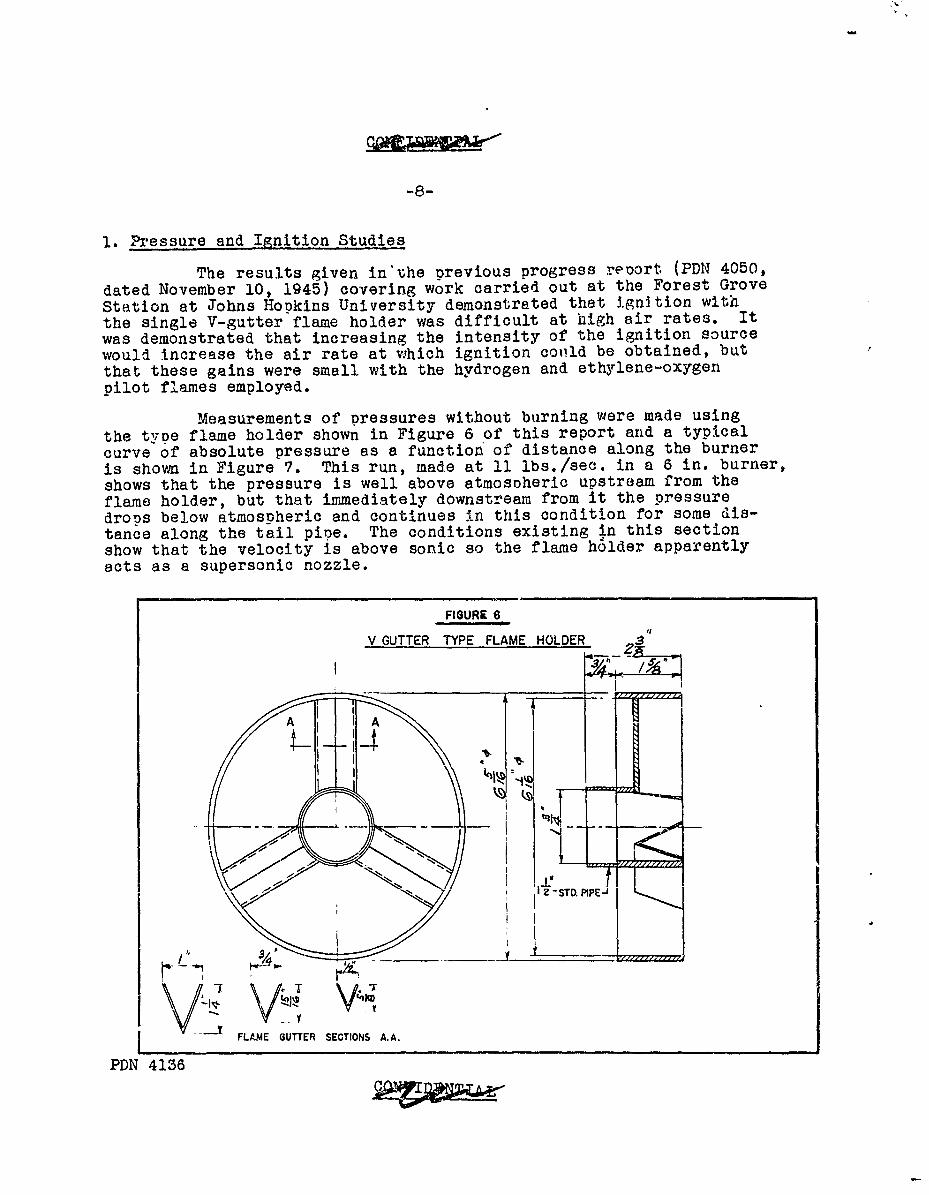
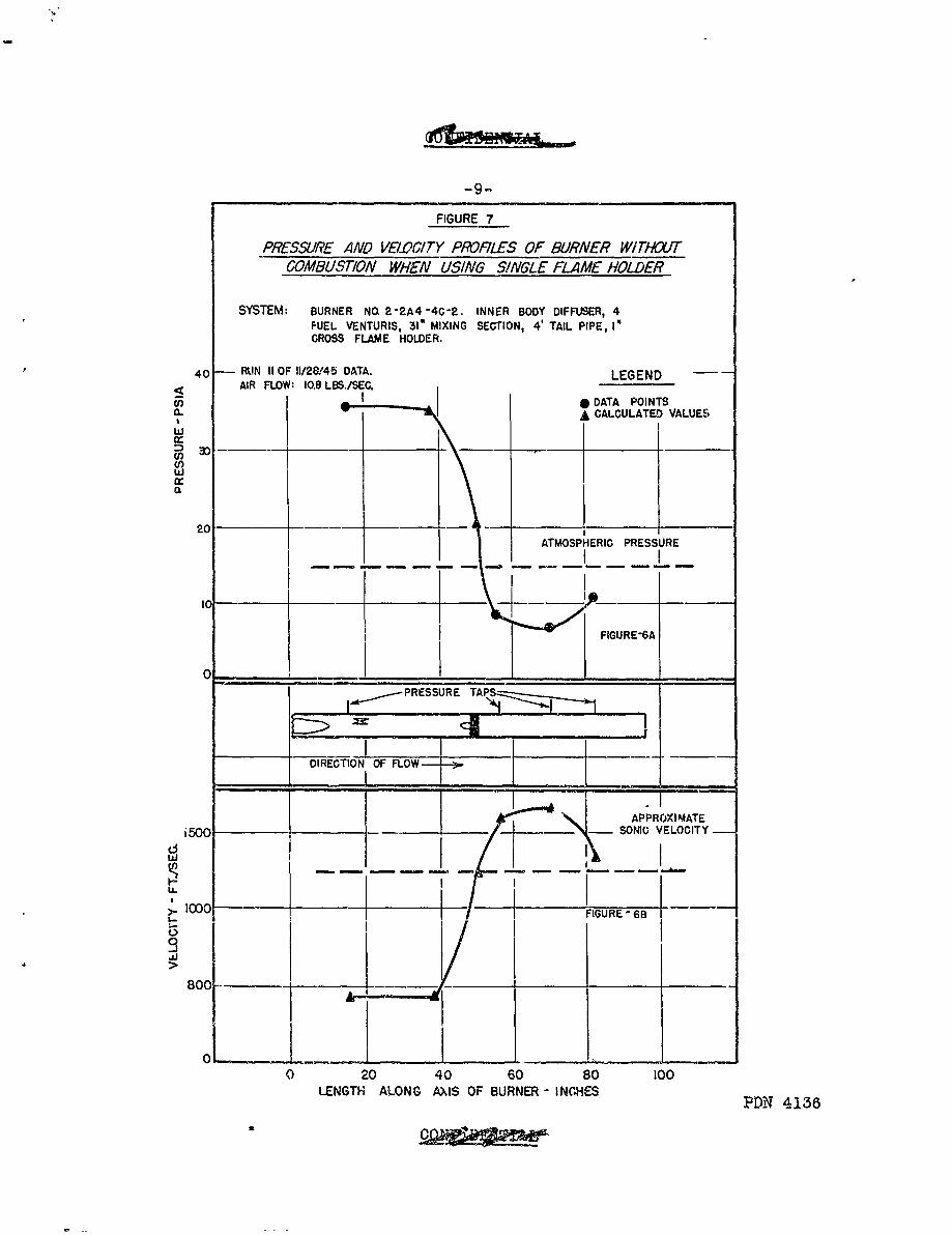
Measurements of pressures without burning were made usingthe type flame holder shown in Figure 6 of this report and a typicalcurve of absolute pressure as a function'of distance along the burneris shown in Figure 7. This run, made at 11 lbs./sec. in a 6 in. burner,shows that the pressure is well above atmosoheric upstream from theflame holder, but that immediately downstream from it the pressure
drops below atmospheric and continues in this condition for some dis-
tance along the tail pioe. The conditions existing in this sectionshow that the velocity is above sonic so the flame h6lder apparentlyects as a supersonic nozzle.
FIGURE 6
V GUTTER TYPE FLAME HOLDER 3
A A
_ I_ . ___
FLAME GUTTER SECTIONS A.A.
PDN 4136
-9-
FIGURE 7
PRESSURE AND VELOCITY PROFILES OF BURNER W/TAHUTCOMBUSTION WHEN USING S!NGLE FLAME HOLDER
SYSTEM: BURNER NO. 2-2A4 -4C-2. INNER BODY DIFFUSER, 4FUEL VENTURIS, 31" MIXING SECTION, 4' TAIL PIPE, I*GROSS FLAME HOLDER.
40 RUN II OF 11/28,45 DATA. LEGENDAIR FLOW: 10.8 LBS./SEC.
U) DATA POINTSa. -- A CALCULATED VALUES
0:
a)
20
ATMOSPHERIC PRESSURE
FIGURE-6A
0
-.- PRESSURE TAPS
DIRECTION OF FLOW
APPROXI MATEi500 -SONIG VELOCITY
ci
IO00 FIGURE 6B
>
800 -l 1----- --
0CI
0 20 40 60 80 100LENGTH ALONG AXIS OF BURNER - INCHES ?DN 4138
10-
It is known that the spontaneous ignition temperature ofthis type of fuel increases rapidly as the pressure is decreasedbelow one atmosphere; so it was surmised that low pressure immediatelydownstream from the flame holder was at least partly responsible forthe ignition difficulties.
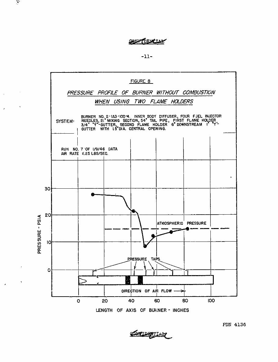
In an effort to initiate ignition in a zone of higher pres-sure a burner was tried with two flame holders in series with the pointof ignitlon in the central cavity of the upstream flame holder. Pres-sure as a function of distance along the burner for such a system isshown in Figure 8. It can be seen that the pressure is above atmos-pheric between the two flame holders, and that it drops below atmos-pheric downstream from the downstream flame holder. It was found thata spark placed in the center of the upstream flame holder gave re-liable ignition at an air rate of 11 lbs./sec. while with a singleflame hol~er ignition could not be obtained at this air rate evenwith large heat inputs from a pilot flame. With this type of burnerthe spark was not needed once combustion was established.
PDN 4136
a
-ll-
FIGURE 8
PRESSURE PROFILE OF BURNER WITHOUT COMBUSTION
WHEN USING TWO FLAME HOLDERS
BURNER NO. 2-IA3IOD-4. INNER BODY DIFFUSER, FOUR FJEL INJECTORSYSTEM: NEEDLES. 21 MIXING SECTION, 54" TAIL PIPE, FIRST FLAME HOLDER
3/4' ""'-GUTTER, SECOND FLAME HOLDER 6" DOWNSTREAM I* Y"-GUTTER WITH L5 DIA. CENTRAL OPENING.
RUN NO. 7'OF 1/9/46 DATAAIR RATE 11.25 LBS/SEC.
30
4 20 'iATMOSPHER.G PRESSURE
I I0wcc
w
PRESSURE TAPS
IIDIRECTION OF AIR FLOW -- i
0 20 40 60 80 100
LENGTH OF AXIS OF BURNER - INCHES
PDN 4136
-12-
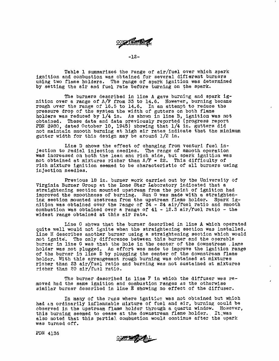
Table 1 summarizes the range of air/fuel over which sparkignition and combustion was obtained for several different burnersusing two flame holders. The range of spark ignition was determinedby setting the air and fuel rate before turning on the spark.
The burners described in line A gave burning and spark ig-nition over a range of A/F from 33 to 14.6. Howeer, burning becamerough uver the range of 16.5 to 14.6. In an attempt to reduce thepressure drop of the system the width of gutters on both flameholders was reduced by 1/4 in. As shown in line B, ignition was notobtained. These data and data previously reported (progress reportPDN 3980, dated October 10, 1945) showing that 1/4 in. gutters didnot maintain smooth burning at high air rates indicate that the minimumgutter width for this design may be around 1/2 in.
Line D shows the effect of changing from venturi fuel in-jection to radial injection needles. The range of smooth operationwas increased on both the lean and rich side, but spark ignition wasnot obtained at mixtures richer than A/F - 22. This difficulty ofrich mixture ignition seemed to be characteristic of all burners usinginjection needles.
Previous 18 in. burner work carried out by the University ofVirginia Burner Group at the lone Star Laboratory indicated that astraightening section mounted upstream from the point of ignition hadimproved the smoothness of burning. Run G was made with a straighten-ing section mounted upstream from the upstream flame holder. Spark ig-nition was obtained over the range of 34 - 24 air/fuel ratio and smoothcombustion was obtained over a rangs of 41 - 12.3 air/fuel ratio -. thewidest range obtained at this air rate.
Line C shows that the burner described in line A which operatedquite well would not ignite when the straightening section was installed.Line H describes another burner using a straightening section which wouldnot ignite. The only difference between this burner and the operableburner in line G was that the hole in the center of the downstream lameholder was not plugged. An effort was made to improve the ignition rangeof the burner in line D by plugging the center of the downstream flameholder. With this arrangement rough burning was obtained at mixturesricher than 23 air/fuel ratio and burning was not sustained at mixturesricher than 20 air/fuel ratio.
The burner described in line F in which the diffuser was re-moved had the same ignition and combustion ranges as the otherwisesimilar burner described in line E showing no effect of the diffuser.
In many of the runs where ignition was not obtained but whichhad Ln ordinarily inflammable mixture of fuel and air, burning could beobserved in the upstream flame holder through a quartz window. However,this burning seemed to cease at the downstream flame holder.. It-wasalso noted that this partial. combustion would continue after the uparkwas turned off.
PDN 4136
C' ' LO
-13-
0 0 0
.10 '0 1 4 r. c C2 l .
00.H er 0 0 N Cj N
W544
0O 0o 0 0 C- ~
r_- to
a! c t to) to N0
z ) om - 4N N -.0
0 ~ 4)
4) 04oo 0
0 10
F) 0 co Z t
.43
0 .- 4 4; ~ 4 -
o 0 C
0
co C3 C: z 0l cH V~ 0. 0 CD0I
o co 0 0 0 o a 0
1) 0 Ml 14 'd M(D54 0 0 0 0D .
o3 0 j 43 4- 0. A 3 0 0 .4 40 4- 44 4- 4 4 0 0 4P 0 0
S = 0 0 z 011 0 - 05 0 oo
co 0
C) t. -4 r 0 0 0 0 00 I.3 54 5 4 4U 5'04U
0l 0 0 00 0.0 $4) ) 4 ) 40 40 4
o0 E- A4~ 0 0 0 0-4 0-C-
0 : -4 .4 4 .-4 .-4 a- te..
42 4' 43 N. 043
ro. ai t a.
0 0 1 0 r-co- $4- A5 4 4 . 4 4 .) I
;4 4) 0 3 4.) C) .c+i4 " ) 43m
43 404 p0 )4) 4 4)4 m )4 55C 0 .30 001 00 c4) w obo t) l to 0
to 14 r.~ (D
C~~t 10t4) -
S0 0w to. 0 0O 0 -d.4 0.4 'rl 54 5 54 4 r 4 544 544)
0 04 0 OU 0 0 00U 0
0 0 0 0 0 0 0 0 0
0 ~ ~ ~ ~ ~ ~ ~ D 4136W o .) otO.4'
ci A02 - S S 3.- C-4 0
-14-
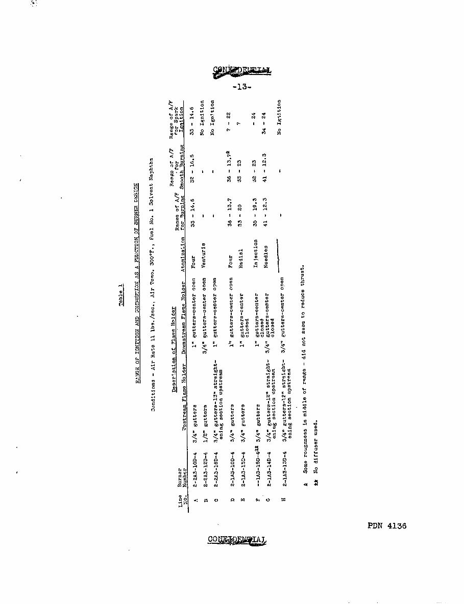
2. Burner Performance
Information on burner perrormance based on thrust measure-ments is available for some of the later runs. The thrust meter usedin these runs measured the momentum of the jet leaving the tail pipe.The thrust discussed in this report is the thrust meter reading minusthe momentum of the unburned mixture just before initiation of com-bustion. This momentum is estimated from the flow rate, pressure andtemperature of the fuel-air mixture.
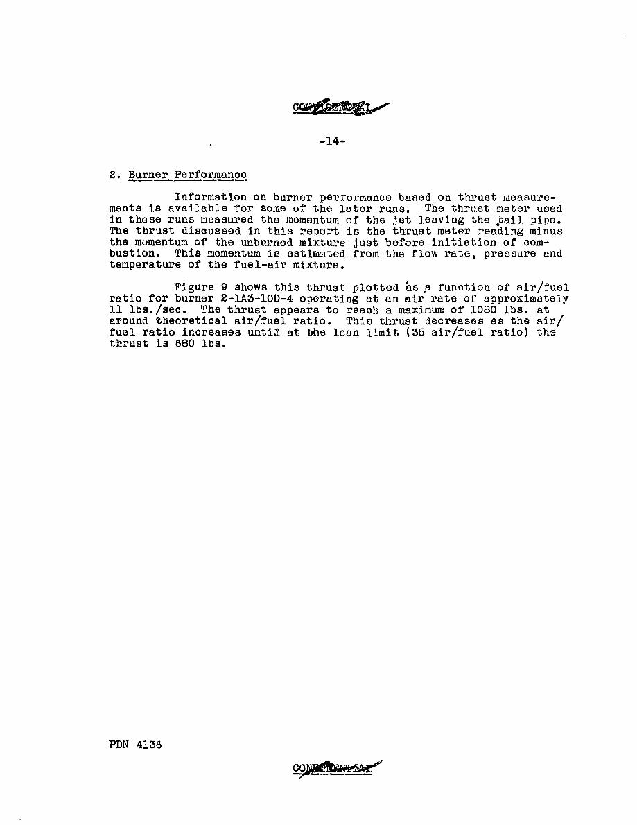
Figure 9 shows this thrust plotted as a function of sir/fuelratio for burner 2-1A3-1OD-4 operating at an air rate of approximately11 lbs./sec. The thrust appears to reach a maximum of 1080 lbs. ataround theoretical air/fuel ratio. This thrust decreases as the air/fuel ratio increases until at the lean limit (35 air/fuel ratio) th3thrust is 680 lbs.
PDN 4136
-15-
FIGURE 9
THRUST OF BURNER WITH TWO FLAME HOLDER
BURNER NO.2-IA3- IOD-4. INNER BODY DIFFUSER, FOUR FUEL INJECTORNEEDLES, 21" MIXING SECTION, 54" TAIL PIPE, FIRST FLAME HLDER 3/4"
SYSTEM, ,Y"-GUTTER, SECOND FLAME HOLDER 6" DOWNSTREAM I" Yo-GUTTERWITH L5" DIA. CENTRAL OPENING.
DATA OF 1/9/46 -AIR FLOWS 10.73-11.19 LBS/SEC.
1200 -
1000 1
800
.600
400
200
PDN 4156
10 20 30 40AIR/FUEL RATIO
-IO-
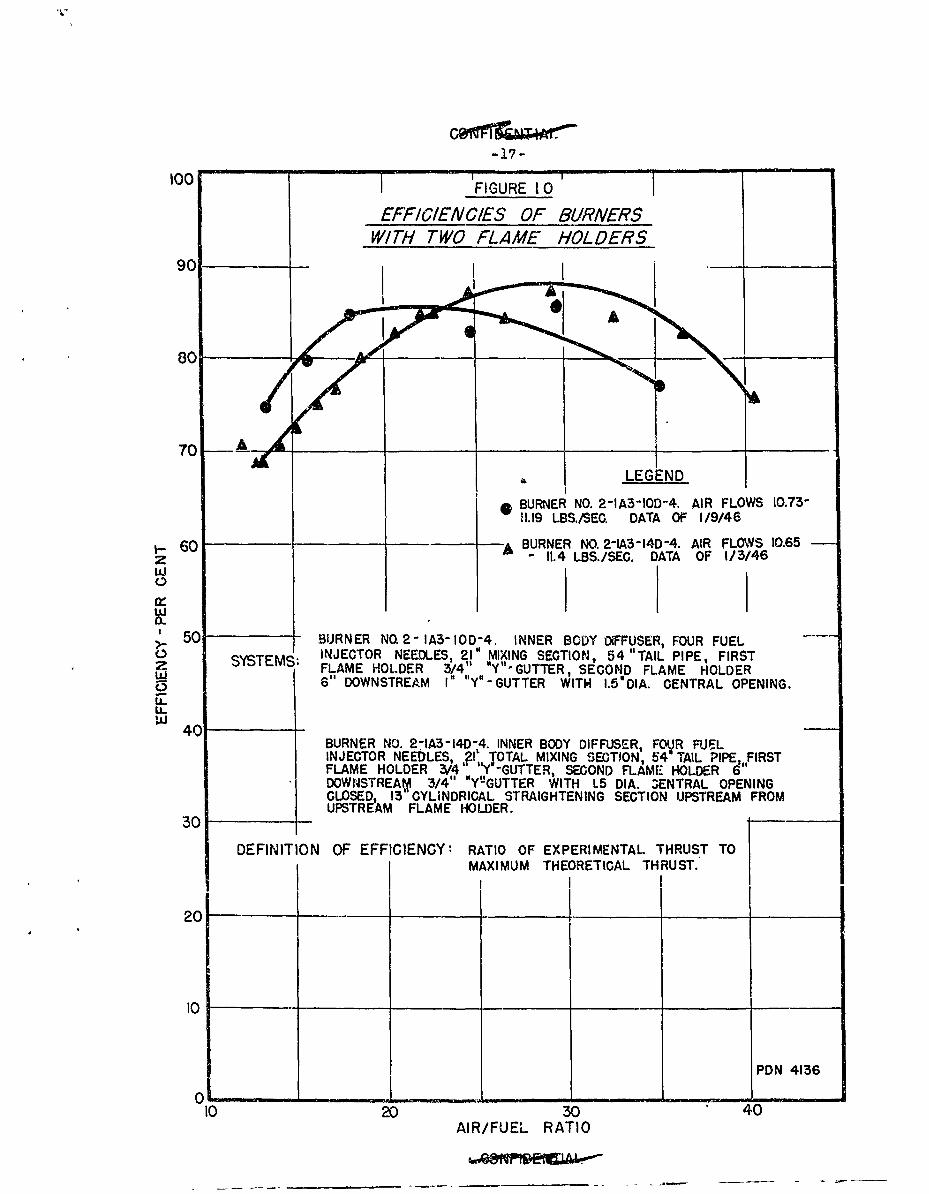
The maximum thrust obtainab!G from the air and fuel rate em-ployed has been calculated assuming an equilibrium mixture, no heat .losses end adiabatic expansion of the jet to atmospheric pressure. InFigure 10 the ratio of measured thrust to this theoretical thrust isplotted as a function of air/fael ratio for two burners. :This ef-ficiency denends primarily on the completeness of mixing and combus-tion and on the efficiency of expansion of the jet.
The two burners used to obtain the data in Figure 10 arequite similar except that the burner whose Derformance is representedby the triangles had a straightening section upstream from the upstreamflame holder and its downstream flame holder had 3/4 in. gutters in-stead of the 1 in. gutters used in the other burner. In the region ofrich mixtures it can be seen that the addition of the straighteningsection and narrowing of the gutters resulted in a lower efficiency al-though a wider range of operation was obtained and efficiency was bet-ter for lean mixtures. It was observed that the burner with thestraightening section gave much lower tail pipe temDerature than theothers. With this burner extended operation at theoretical air/fuGlratio did not seem to harm the tail pipe while with Vhe other burner,operation for a oeriod of much more than a minute was likely to destroyit.
PDN 4136
100 TFIGURE 10
EFFICIEN CIES OF BURNERSWITH rwo FLAME HOLDERS
70 A
*BURNER NO. 2-IA3IO0D-4. AIR FLOWS 10.73-11.19 LBS./SEC. DATA OF 1/9/46
1- 60 BAEURNER NO. 2-tA3-140-4. AIR FLOWS 10.65z -11.4 LBS./SEC. DATA OF 1/3/46w0
50 BURNER NO.2- IA3- IOD-4. INNER BODY DiFFUSER, FOUR FUELSYSTMS;INJECTOR NEEDLES, 21" MIXING SECTION, 54 "TAIL PIPE, FIRSTSYSTMS.FLAME HOL.DER 3/4", syll GUTTER, SECOND FLAME HOLDER
w ~6" DOWNSTREAM I" N' -GUTTER WITH I.5'DIA. CENTRAL OPENING.U-u-
IAJ 401BURNER NO. 2-1A3-I40-4. INNER BODY DIFFUSER, FOVR FUJELINJECTOR NEEDLES ?I' TOTAL MIXING SECTION, 64 TAIL PIPE,FIRSTFLAME HOLDER 3/4 ''Y -GUTTER, SECOND FLAME HOLDER 6DOWNSTREA , 3/4" V-GUTTER WITH L5 DIA. 3ENTRAL OPENINGCLOSED, 13' CYLINDRICAL STRAIGHTENING SECTION UPSTREAM FROMUPSTREAM FLAME HOLDER.
30
DEFINITION OF EFFICIENCY: RATIO OF EXPERIMENTAL THRUST TOMAXIMUM THEORETICAL THRUST.
20 -_____ __ _
PDN 4136
10 20 30 40AIR/FUEL RATIO
-18-
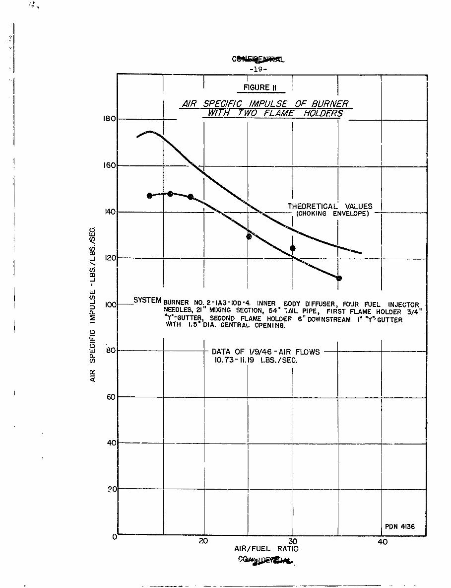
In Figure 11 air specific impulse is plotted as a function ofair/fuel ratio. Air snecific imoulse is defined as:
Am
Yhere P is the absolute pressure of the unburned mixture which is neces-3ary to give the thrust observed if there is no friction in the system.
0 is the gas density corresponding tc the above pressure at the tent-perature before initiation of combustion.
r is: the velocity of the gas under the above conditions.
is the burner area at the point of the above conditions.
a is the rate of air flow in mass/unit time.
The units used gave the air specific impulse in lbs./lb./sec.1'he theoretical curve was calculated assuming combustion to equilibriulnd adiabatic expansion of the jet with no heat losses in the system.
Air specific impulse, a number related to thrust per lb. ofiir, is of value in studying the overall performance of a ram-jet andias been adopted by JHU for representing burner data. With this)articular burner the maximum air specific impulse was 148 lbs./lb./sec.t'-other burner (2-LA3-10D-4) gave a maximum value of 151.
PDN 4136
*FGURE II
AIR SPECIF/C IMPULSE OF BURNER180 WITH TWO FLAME HOLDERS
160 _ _ __ _ _
O THEORETICAL VALUES
140 (CHOKING ENVELOPE) -
CjA
-i
Jlo -0 SYSTEM BURNER NO.2-1A3-10D-4. INNER BODY DIFFUSER, FOUR FUEL INJECTORD NEEDLES, 21" MIXING SECTION, 540 "AlL PIPE, FIRST FLAME HOLDER 3/4"_ "Y'-GUTTER, SECOND FLAME HOLDER 6" DOWNSTREAM I" "Y"GUTTER
WITH 1.5' DIA. CENTRAL OPENING.0
w 80 - DATA OF 1/9/46 - AIR FLOWScnO 10.73-11.19 LBS./SEC.n,-
60
40
-Ji PDN 4136
20 30 40AIR/FUEL RATIO
-20-
3. Dra of the Burner Interior
A pressure measurement upstream from tho Luel injection com-bined with the thrust measurement made ossible the oaloulation of thetotal drag of the fuel injectior system, the ignition and flame holdersystems and the burner walls under the conditions existing during burning.
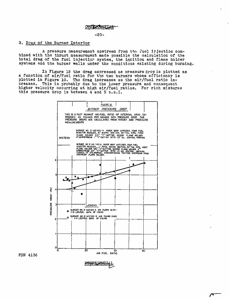
In Figure 12 the drag expressed as pressure drop is plotted asa function of air/fuel ratio for the two burners whose efficiency isplotted in Figure 10. The drag increases as the air/fuel ratio in-creases. This is probably due to the lower pressure and consequenthigher velocity occurring at high air/fuel ratios. For rich mixturesthis pressure drop is between 4 and 5 p.s.i.
FIURE 12
BUNER PRESSURE DROP
THIS IS A PLOT AGAINST AIR/FUEL RATIO OF INTERNAL DRAG EX-PRESSED AS POUNDS PER SQUARE INCH PRESSURE DROP THEPRESSURE DROPS ARE CALCULATED FROM THRUST AND PRESSUREMEASUREMENTS
BURNER NO 2-1A3-100-4 INNER BODY DIFFUSER, FOUR FUELINJECTOR NEEDLES, 21- MIXING SEC*;ION, 54"TAL PIPE, FIRSTFAME HOLDER 314- "Y -GUTTER, SE ONr FLAME HO.DER
SYSTEMS- 6 DOWNSTREAM ]'Y'-Gf'ER WITH 1.5 " I ENTRAL OPENING
BRNER NO 2-1A5-1404 INNER BODY DIFFUSER, FLJR FUELINJECTOR NEEDLES -i' TOTAL MIXING SECTION, 54"TAL PIPE, FIRSTFLAME HOLDER 34 ."Y.'GUTTER SECOND FLAME HOLDER 6DOWNSTREAI Z,4 Y GUTTER WITH 1.5 DIA CENTRAL OPENINGCLOSED 13 CYLINDRICAL STRAIGHTENING SECTION UPSTREAM FROMUPSTRE.& FLAME HOLUDR.
4 -__
00
Cr,,. 3 - LEGEND -t
BURNER NO. 2 -IA3-IOD-4 AIR FLOWS 10.7311.19 LBS/SEC. DATA OF 19/46
BURNER NO. 2-1A3-140 -4 AIR FLOWS 10.65-- A 114 LES/SEC. DATA OF 1/3/46
I II I
0 20 0 40
PDN 4136 AIR FUEL RATIO
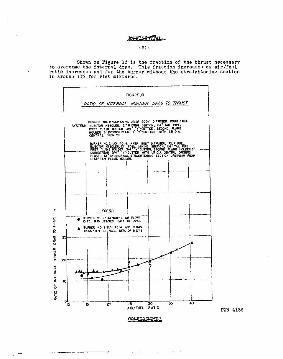
Shown on Figure 13 is the fraction of the thrust necessaryto overcome the internal drag. This fraction increases as air/fuelratio increases and for the burner without the straightening sectionis around 110% for rich mixtures.
FIGURE 13
RATIO OF lA/ERNAL BLURNER DRAG 70 T*PJST
BURNER NO. 21IA3100D-4. INNER BODY DIFFUSER, FOUR FUELSY~STEM: INJECTOR NEEDLES,, 2I' MIXING SECTION, 54' TAIL PIPE,
FIRST FLAME HOLDER 314" PYL~GUTTER , SECOND FLAMEHOLDER 6" DOWNSTREAM '1' "Yl'IGUTTER WITH 1. 5 DI A.CENTRAL OPENING.
BURNER NQ 2-1A3-14D,4. INNER BODY DIFFUSER, FOVR FUELINJECTOR W~EDLES, 21' TO14 ,IX ING SECTION 54 TAIL PIPEFIRST -LAME HOLqt ,3/4 Y GUTTER SECON6 FLAME HOLDER 6DOWNSTREAM V/4' Y - GUTTER WITH 15 DIA. CENTRAL OPENINGCLOSED, 13' CYI.INDRICAL STRAIGHTENING SECTION UPSTREAM FROMUPSTREAM FLAME HOLDER.
L EG END
*BURNER NO, 2-IA3-I0D-4. AIR FLOWS0.73 -11 19 LBS/SEC. DATA OF I$'46
ABURNER NO, 2-A3-14D-4. AIR FLOWS10.65-11.4 LBS/SEC. DTA OF 1/3/46
20
1 00j
-f
101 0253 54AI/FELRAI
35N 403
............... A.R/FUEL ... ATIO.......
CONFIDENTIAL
-22-
FUTURE PROGRAM
The immediate program will be devoted to adapting thegu'ter type of flame holder to flying mcdel testing. The programwill include the study of flare ignition in this tyie of flameholder, and a study of its performance with the Cobra diffuser.It is planned that some tests of the Cobra ignition system will bemade to give comparative results.
The data in the section on oressure and ignition studiesemphasize the sensitivity of these burners to changes in the flowpattern of the air. These changes are not sufficiently well under-stood to enable reliable prediction of the effect of changing thegeometry of the burner. Some of the work in the immediate futurewill be devoted to this asoect cf the problem.
PDN 4136
CONFIDENTIAL
-23-
APPENDIX
1. System for Numbering Burners
A system which designates each section by a number has been
adopted.
The sections designated by separate numbers are:
1. Diffuser section2. Atomizing and mixing section3. Flame holder and pilot4. Tail pipe section
Since these numbers will run into two or more figures theywill be separated by dashes. The order of the numbers is that of thepreceeding list.
1. Diffuser Section
2. This section consists of a 5'-2" piece offlanged pipe containing a wooden body 4" in diameter and tapered toa point at the ends. ?See Figure 5)
2. Atomizing and Mixing Section
2A4, Four 1-1/2" venturis with upstream injectionat their throat are mounted with one in the center and the other threearranged on the corners of an equilateral triangle about tile centerone. The distance between the fuel injection and the flame holder is31 inches.
2A3. Same as above except that the distance be-tween fuel injection and flame holder is 21 inches.
1A3. Same as above except that radial injectionneedles were used instead of venturis.
3. Flame Holder Section
Three types of flame holders were used to make upthe-various combinations reported here.
4. This flame holdir, shown in Figure 2 of theOctober progress report (PDN -3980) has 3ne inch gutters arranged in theshape of a cross.
Figure 6 of this report describes the type known asY-gutter flame holders; the gutters are arranged in the shape of a "Y".
PDN 4136
CONFIDENTIAL
-24-
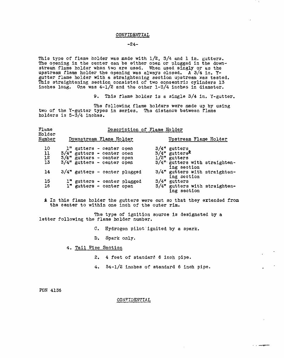
This type of flame holder was made with 1/2, 3/4 and 1 in. gutters.The opening in the center can be either open or plugged in the down-stream flame holder when two are used. When used singly or as theupstream flame holder the opening was always closed. A 3/4 in. Y-gutter flame holder with a straightening section upstream was tested.This straightening section consisted of two concentric cylinders 13inches long. One was 4-1/2 and the other 1-3/4 inches in diameter.
9. This flame holder is a single 3/4 in. Y-gutter.
The following flame holders were made up by usingtwo of the Y-gutter types in series. The distance between flameholders is 5-3/4 inches.
Flame Description of Flame HolderHolderNumber Downstream Flame Holder UDstream Flame Holder
10 1" gutters - center open 3/4" gutters11 3/4" gutters - center ooen 3/4" guttersl12 3/4" gutters - center open 1/2" gutters13 3/4" gutters - center open 3/4" gutters with straighten-
ing section14 3/4" gutters - center plugged 3/4" gutters with straighten-
ing section15 1" gutters - center plugged 3/4" gutters16 1" gutters - center open 3/4" gutters with straighten-
ing section
A In this flame holder the gutters were cut so that they extended fromthe center to within one inch of the outer rim.
The type of ignition source is designated by a
letter following the flame holder number.
C. Hydrogen pilot ignited by a spark.
D. Spark only.
4. Tail Pipe Section
2. 4 feet of standard 6 inch pipe.
4. 54-1/2 inches of standard 6 inch pipe.
PDN 4136
CON FIDENTIAL
-25-
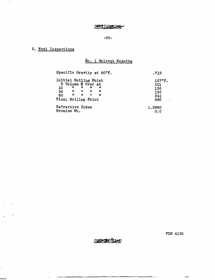
2. Fuel Inspections
No. I Solvent Napitha
Specific Gravity at 600F. .715
Initial Boiling Point 127 0F.5 Volume % Over at 151
10 " " " 15650 19090 241
Final Boiling Point 286
Refractive Index 1.3980Bromine No. 0.0
PDN 4136
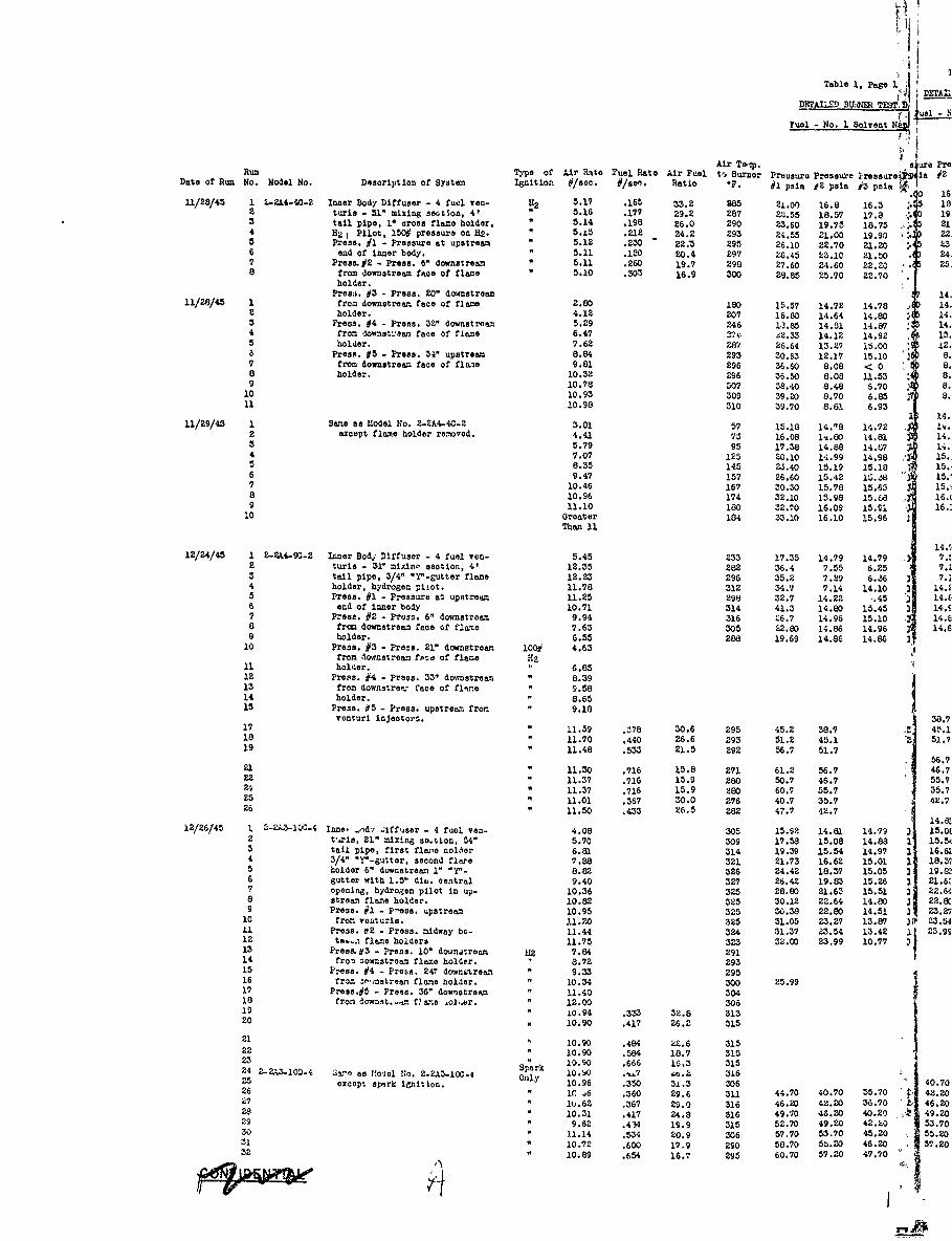
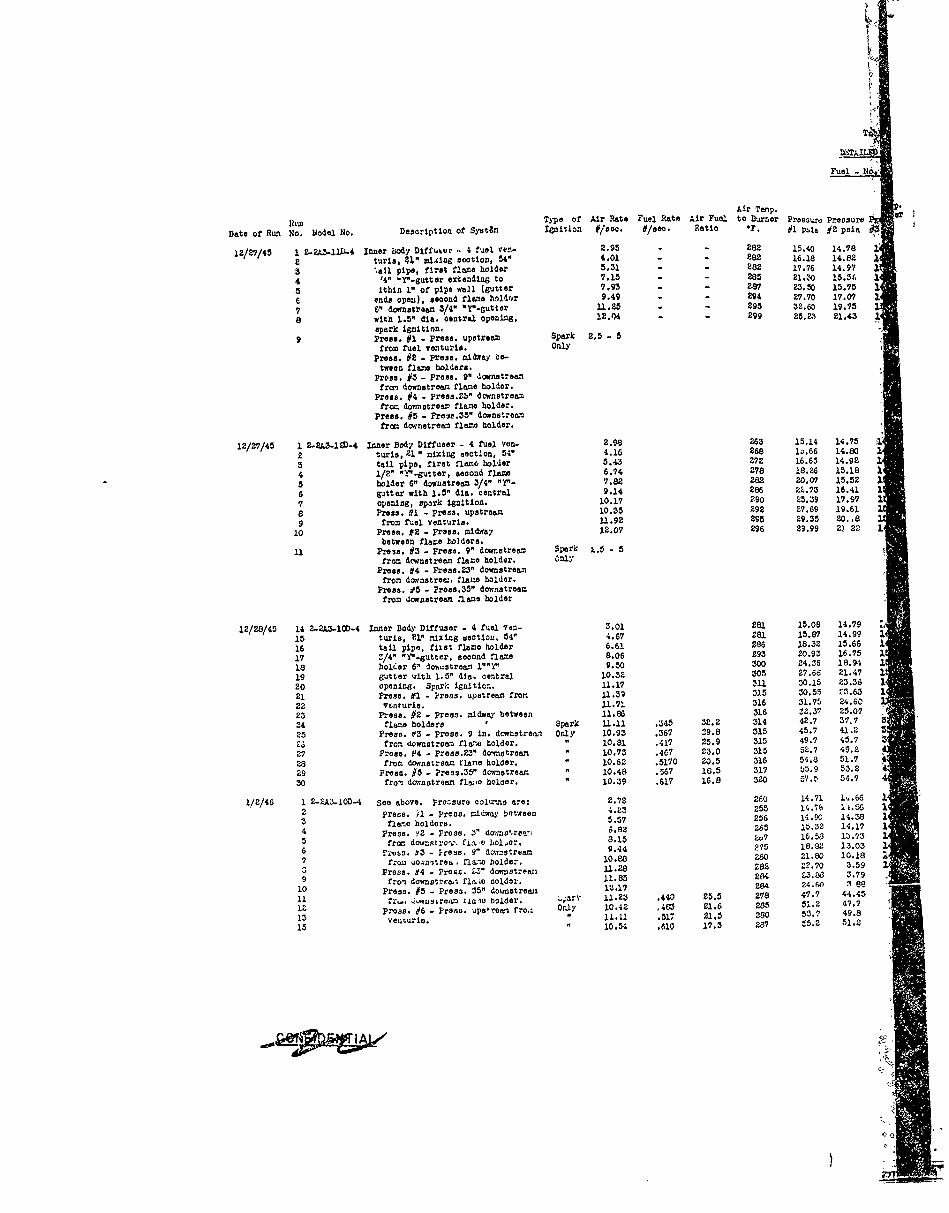
Table 1, Page 1,;4M h-Y -- B+ E TEST,, LETAI
DETAILE' BU.8~2 .11). _
Pul - No. 1 Solvent Na
Air Tep. u PRun Type of Air Rate Fuel Rate Air Fuel to Burner Pressure Pressure Ir eaure" ? i 2Date or Run No. Model No. Description of System Ignition #/sos. #/se.. Ratio *F. #i psia 2 ple #3 psia le
11/28/45 1 L-2A44-O-2 Inner Body Diffuser - 4 fuel van- H 5.17 .166 33.2 285 2.00 16.8 16.3 ..452 turis - 51" mixing se4t0on, 4' 5.16 .177 29.2 287 P-.55 18.57 17.8 0 193 tail pipe, 1" cross flame holder, " 5.14 .198 26.0 290 23.60 19.75 18.75 5. 214 H2 I Pilot, 151# pressure on H2. " 5.13 .212 24.2 293 24.55 21.00 19.90 :. 225 Press. #i - Pressure at upstream " 5.12 .230 22.3 295 26.10 22.70 21.0 5 36 end of inner body. " 5.11 .150 20.4 297 26.45 L3.10 21.50 . 247 Pros.Y2 - Press. 6" downstream " 5.11 .260 19.7 298 27.60 24.60 22.20 . 258 from downstream face of flame " 5.10 .303 16.9 300 28.85 25.70 22.70
holder.
Pree,. #3 - Press. 20" dawnstream 1411/28/45 1 from downstream face of flame 2.80 180 15.57 14.72 14.78 142 holder. 4.12 207 16.80 14.64 14.80 143 Press. #4 - Press. 32" downstroam 5.29 246 1,3.85 14.51 14.87 144 from downat'.en face of flame 6.47 2 1 32.33 14.12 14.92 135 holder. 7.62 2W? 26.64 13.29 i5.00 126 Press. #5 - Press. 34" upotrean 8.84 293 30.93 12.17 15.10 87 from downstream face of flze 9.81 296 56.60 8.08 < 0 88 holder. 10.32 296 36.50 8.08 11.53 4 89 10.78 Z07 38.40 8.48 6.70 1 8
10 10.93 309 39.20 8.70 6.85 5.11 10.98 310 39.70 8.81 6.93
1 14.11/29/45 1 Same as Model No. 2-2A4-4C-2 3.01 57 15.18 14.18 14.72 . 1'.
2 except flame holder re.oved. 4.41 73 16.08 1..80 14.81 143 5.79 95 17.38 14.88 14.67 14.4 7.07 125 20,10 14.99 14.98 ' 15.5 8.35 145 2.5.40 15.19 15.18 15.6 9.47 157 26.60 15.42 L;._ 15.7 10.46 167 30.30 15.78 15.63 15.8 10.96 174 32.10 15.98 15.68 16.9 11.10 180 32.70 16.09 15.9i 16.10 Greater 184 33.10 16.10 15.96 1
Than 11
14.12/24/45 1 2-ZA4-9G-2 Inner Bodj Diffuser - 4 fuel yen- 5.45 233 17.35 14.79 14.79 7.2 turis - 31" mixin, section, 4' 12.35 282 36.4 7.55 6.25 7.3 tail pipe, 3/4" "Y"-gutter flame 12.23 296 35.2 7.29 6..6 3 7.;4 holder, hydrogen piot. 11.78 312 34.7 7.14 14.10 3 14.;5 Press. #1 - Preesure at upstream 11.25 298 32.7 14.22 .45 ) 1.6 end of inner body 10.71 314 41.3 14.30 15.45 3 14.7 Fr.eos. #2 - Preoss. 6" downstream 9.94 316 26.7 14.96 15.10 14.18 from downstream face of flaeo 7.63 305 22.80 14.86 14.96 14J9 holder. 6.55 288 19.69 14.86 14.8610 Prone. #3 - Press. 21" downstream 100# 4.63
from downstream fece of flame H2
11 holder. 6.8512 Press. #4 - Press. 33" downstream " 8.3913 from downotre. face of flano " 9.5814 holder. " 8.6515 Press. 05 - Press. upstream from " 9.10
venturi injectors.17 " Zi.59 .z78 30.6 295 45.2 38.7 45.318 " 11.70 .440 26.6 293 51.2 45.1 51.119 " 11.48 .533 21.5 292 56.7 51.7
56.721 " 11.30 .716 15.8 271 61.2 56.7 46.722" 11.37 .716 15.9 280 50.7 46.7 55.724 " 11.37 .716 15.9 280 60.7 55.7 35.725 " 11.01 .367 30.0 276 40.7 35.7 42.726 ". 11.50 .4,33 26.5 282 47.7 42.7
14.a12/26/45 1 --ZA3-j. -4 Inns, .ndv .iff'iser - 4 fuel ven- 4.08 305 15.92 14.81 14.79 2 15.02 tVn'l, 21" mixing sotion, 34" 5.70 309 17.58 15.08 14.83 1 15.53 tail pipe, first flae noldor 6.81 314 19.39 15.54 14.97 2 16.64 3/4" "r-guttor, second flare 7.88 321 21.73 16.62 15.01 1 18.a5 holder 6" downstream 1" "'- 8.82 326 24.42 18.37 15.05 2 19.86 gutter with 1.51 dia. central 9.40 327 26.42 19.85 15.26 1 21.67 opening, hydrogen pilot in up- 10.36 325 28.80 21.63 15.51 2 22.6,8 strean flame holder. 10.82 325 30.12 22.64 14.80 3 22.9 Press. #1 - P"ess. upstream 10.95 325 30.38 22.80 14.51 2 23.210 from vonturis. X1.20 325 31.05 23.27 13.87 1 23.5,
11 Press. f2 - Press. nidway be- 11.44 324 31.37 23.54 13.42 2. 23.9112 tw., flame holders 11.75 323 32.00 23.99 10.77 2113 Preos. &3 - Press. 10" do inatream 112 7.84 291 114 fro? Qowrntroam flame holder. 1 8.72 29315 Press. #4 - Press. 24 do*nitream " 9.33 29516 from a-'rastrean flame holder. " 10.34 300 25.9917 Preso.#5 - Press. 36" dowustream " 11.40 30418 from downet ),. ea."o +oJ'.er. " 12.00 30619 " W0.94 .333 32.6 31320 10.90 .417 26.2 315
21 10.90 .484 U2.6 31522 " 10.90 .584 18.7 3152 " 10.90 .666 16.3 31524 2-2A3-IOD.4 - as l.o'kol No. 212A3-100-4 O0. 0 ..7 '.k. 316Sien 1llN.2Z31C4 Only 40.7025 except apnrk i nition. 10.96 .350 3L.3 30626 " I, 6 .360 29.6 311 44.70 40.70 35.7027 " 1j.6
2 .367 29.0 316 46.20 4Z.20 36.70 46.20
28 10.31 .417 24.8 316 49.70 46.20 40.20 49.2029 " 9.62 .434 19.9 315 52.70 49.20 42.20 53.7030 - 11.14 .534 20.9 306 57.70 53.70 45.20 55.2031 " 10.72 .600 17.9 290 58.70 55. 20 46.20 57.2032 " 10.89 .654 16.7 295 60.70 59.20 47.'10
Table1, Page Flm eLEM=I.! MIMI) TIST DATAj !us) - No. 1 Solvent Na, tha
Ratio
Air Sp. to Theoreticala ure Pressure prelsure ?r'seuro Pressure Preossure Thrust Sp.Thruet Efficiency ImPulso ical - Air
roe sa J2 pala J3 peie 44 psia j5 pfia r6 psia # #/$/Boo. % #//r/toc. Sp.Impul1e % Notes and Conentaa 16.8 16.3 15.65 19.85 60.8 392 26.2
18.5? 17,8 16.65 21.60 108.8 615 41.819.75 18.75 17.35 22.70 144.5 730 50.621.00 19.90 18.10 23.70 177.8 838 58.422.70 21.20 18.90 '25.30 230.3 1002 71.5L3.10 21.b0 19.15 26.60 242.7 972 70.5 Pipe red24.60 22.20 19.25 27.00 296.0 1138 83.625.70 22.70 19.40 28.20 334.7 1107 84.8 Pipe quite red, pips very
hot for two feet.
14.72 14.78 14.73 15.2814.64 14.80 14.79 16.1014.51 14.87 14.82 17.6314.12 14.92 14.85 20.4413.27 15.00 14.92 24.3212.17 15.10 15.03 28.228.08 < 0 <. 0 33.058.08 11.53 14.48 33.78.48 6.70 12.72 35.28.70 6.85 10.75 35.78.81 6.93 6.95 36.4
14.78 14.72 14.71 14.881.80 14.81 14.78 15.1214.38 14.8? 14.80 15.8014.99 14.98 14.89 17.1215.19 15.18 14.99 18.9115.42 15.38 15.10 21.2015.78 15.65 15.30 2?7.6215.98 15.88 15.43 25.1016.09 15.91 15:49 25.7016.10 15.96 15.56 25.74
14.79 14.79 14.78 16.297.55 6.25 7.46 31.557.29 6.36 14.7 20.207.14 14.10 15.29 2$.5a14.22 15.45 15.31 28.7914.87 15.45 15.30 27.7014.96 1b.10 15.05 22.8014.86 14.96 14.96 19.8714.86 14.86 14.86 17.72
Ignited
IgnitedIgnitedDid not 1gniteIgnitedDid not igtiet
38.7 30.19 43.7 745 370 72.6 1 Values of Thrust,4.1 34.45 49.7 950 2158 84.0 Specific Thruet51.7 55.7 1158 2170 92.3 end Efficiency
may be solewhat56.7 59.7 1339 1868 92.3 high. Rich Limit46.7 54.7 1059 1478 72.7 >Ignition was55.7 59.7 0 8 initiated at low Rich Limit35.7 39.7 657 1791 68.4 air rates and burner Lean Limit42.7 46.7 879 2027 178.6 then brought up to
indicated air r~te.14.61 14.79 14.81 14.7815.08 14.88 14.92 14.8815.54 14.97 lb.04 14.98
1 16.62 15.01 15.19 15.1018.37 15.05 15.37 15.2419.e3 15.26 15.54 15.3921.63 15.51 15.78 15.5822.64 14.80 15.80 15.18
a 22.80 14.51 15.78 15 6923.27 13.87 15.87 15.75
123.54 13.42 15.9? 15.711 23.99 10.77 15.90 15.n6
IgnitedIgnitedIgnited~ignitedZIgnited
IgnitedIgnitedSet Rates end IgnitedPilot with Spark.
Anterwitt.it Burniag Starts40.70 35.70 30.18 26.67 691.5 1921 75.0 1 Thrint,6p.Thruot eod Smooth Burning Starts42.20 36.70 30 81 9b.93 727.9 1990 78.3 E 2fficienc figures
" i 46.20 40.20 32.50 28.60 845.0 2030 6b.7 may be so'eWhat low,2 49.20 42.20 29.64 915.0 1892 89.5 o siaco they do not
53.70 45.20 31.87 1025.0 1924 83.9 tako into account- 55.20 46.20 31.78 1067.0 1771 83.6 cor.t.,ution ocur-57.20 47.70 3,02 1114.0 1705 82.9 ring between flame
holders.
PDN413
Air Tamp.Type of Air Rate Fuel Rate Air Fuel to Burner Pressure pressure
Date of Run No. Uodel No. Description of Syst&m Ignition #/00. #/Sea. Ratio "F. #i PbA #2 psia Z
12/27/45 1 &g.tA-31lI4 Inner body Diffueor - 4 fuel ven- 2.95 - 282 15.40 14.78 3,2 turs, 4" milag section, 54" 4.01 - - 282 16.18 14,82 33 ,all pipe, first flame holder 5.31 - - 282 17.76 14,97 3.4 14" 'Y"-sutter extending to 7.15 - 285 21.30 15.34
5 ithin 1" of pipe wall (gutter 7.93 - - 207 23,50 15.75
C ends open), second flsar hol4or 9.49 - - 4 27.70 17.07 3.7V6 downstream 3/4- O".gutter 11.21- - - 295 32.603 19.75 3
8 with 1.5" die. central opening. 12.04 - - 299 25.23 21.43 .
spark Ignition.9 Press, #1 - Press. upstream Spark 2.5 - 5
from fuel venturld. Only
Press. #2 - press. midx be-tweec flare holders.
Press. #3 - Press. 9" downstreamfrom downstream flame holder.
Press. #4 - press.23" dcwnstreamfrom downstrear flame holder.
Press. #5 - Press.35" downstreamfrom downstrea= flame holder.
12/27/45 1 2-2A3-19D-4 Inner Body Diffuser - 4 fuel yen- 2.98 263 15.14 14.75
2 turis,21 " mixing section, 54" 4.16 268 lo.66 14.80 1
3 tail pipe, first flamo holder 5.43 272 16.65 14.92 3.4 1/2" "Y"-gUtter, second flaw 6.74 278 18.26 15.18
5 holder 6" downstream 3/4" "Y"- 7.82 282 20.07 15.52 3.6 gtter with 1.5" din. central 9.14 286 2i.73 16.41 3.
7 opening, spark ignition. 10.17 290 25.39 17.97
8 Press. ff1 - press, upstream 10.35 292 27.69 19.61
9 from fuel venturis. 11.92 295 29.35 20. -8 1
10 Press. #2 - press. midway 12.07 296 29.99 2) 22 1between flame holders.
11 Press. #3 - press. 9" downstream Spark 2.6 - 5from downstream flame holder. Cnly
Press. #4 - Fress.23" downstreamfrom dcunstree:, flame holder.
Press. e5 - Press.35" downstreamfrom downstream flame holder
12/28/45 14 2-Z.3-0-4 Inner Body Diffuser . 4 fuel van- 3.01 g81 15.08 14.79 ,15 turn , R1" mi.xing section, 54" 4.67 281 15.87 14.99 1
16 tail pipe, fist flame holder 6.61 286 18.32 15.66 3.17 Z/4" "'"-gutter, second flame 8.06 293 20.93 16.75 2.
18 holCer 6" dovwstream 1""Y" 9.50 300 24.36 18.94 1
19 gutter with 1.5" die. central 10.32 305 27.68 21.47 1
20 opening. Spar: igniticn. 11.17 311 30.15 23.36 1
21 Press. Al - press. upstream from 11.3' D15 30.55 2.63 1
22 vcnturis. L1.71 316 31.75 24.60
23 Press. #2 - press, midway between 11.86 316 12.23 25.07
24 flame holders I Spark 11.11 .345 32.2 314 42.7 37.7 5
25 Press. #3 - press. 9 in. downstrae Only 10.93 .367 29.8 315 45.7 41.2 3
z from downstream flwro holder. " 10.81 .417 25.9 315 49.7 45.7 5
27 Press. 14 - Preas.23" downstrean " 10.73 .467 23.0 315 52.7 49.2
28 from downstream flane bolder. " 10.62 .5170 20.5 316 54.8 51.7
29 Press. #5 - Press.35" downstream " 10.48 .567 10.5 317 b5.9 53.2
30 fro downstreem fla;,o holer. " 10.39 .617 16.8 320 57.5 54.7
1/2/46 1 2-2A3-IOD-4 sea above. Proesure colun4no are: 2.72 260 14.71 i.,.66 I
2 Press. 1 - Press. midway between 4.23 255 1.7; l.56 2.
3 flaoe holders. 5.57 256 14.90 14.38 1
4 Press. ,2 - Press. 3" dAotrean- 6.82 265 15.32 14.17 35frm downstc% . flao holer. 8.15 Lb? 16.58 13.73 2
6 pruvs. h-3 - kress. 9" dronstream 9.44 285 18.82 13.03 1
7 from uo.7n-tre;., flvo holde.-. 10.80 280 21.80 10.18
9 Press. ff4 - prose. L" dovristream 11.28 2 Z2.70 3.59fro downstreai flnio colder. 11.83 2,34 23.80 3.79
10 Press. #5 - Press. 35" downstrem 1;2.17 264 24.F0 . 881I fr,,, Lis~reiu Ila's holder. .;arr 11.85 .440 25.5 218 47.7 44.45
1z press. #6 - Press. upsarem fro.a Only 10.42 '46 21.6 205 51.2 47.7
13 ven1.11. " 11.11 .317 21.3 280 53.7 49.8
15 " 10.54 .610 17.3 287 !5.2 51.2
A
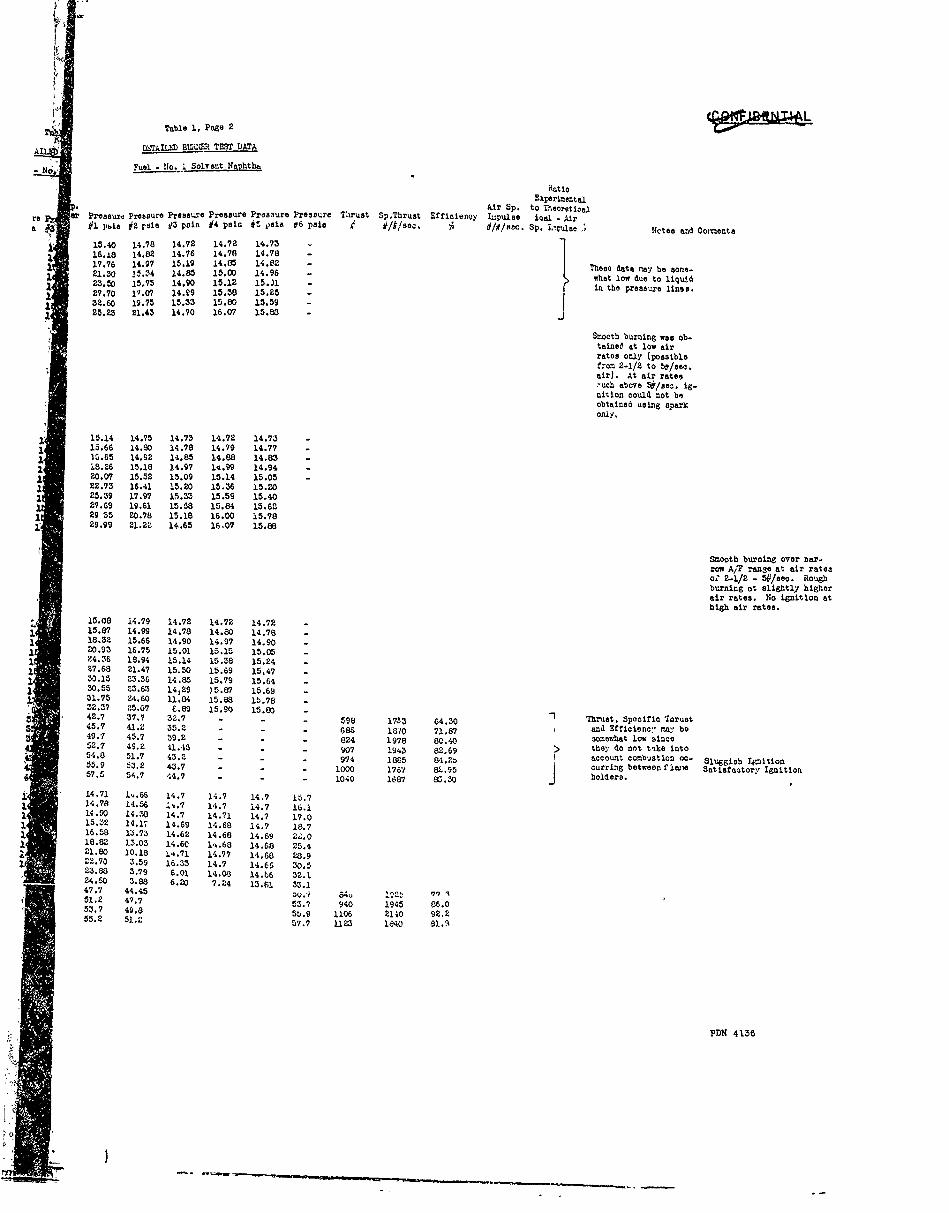
Table 1, Page 2
ADMAILM BMUM TEST DATA
F 8uel - No. I Solvent N ht
Ratio
ExperizentalAir Sp. to Thjoratioal
re pressure Proesure Pressure Pressure Prosiure Pressure Thrust SpThrust Efricieney Iupulse ial - Aira #1 pia #2 rata 3 pain #4 pooin iti a 06 d #lkise. Pa i1s1o. Sp. Apulse .; Ncte and Co'iventa
15.40 14.78 14.72 14.72 14.75 7
16.18 14.82 14.76 14.78 14.78 -17.76 14.97 15.19 14.85 14.82 e-21.30 i.54 14.8 MD 14.96 - Tesawhat low due to liquid
23.50 15.75 14.90 15.12 15.)11 - l ue to liquid
27.70 11.07 14.T9 15.58 15.25 -
52.60 19.75 15.33 15.80 15.59 -25.23 21.45 14.70 16.07 15.80 -
Stooth burning was ob-tained at low airrates only (possible
trom 2-1/2 to .l/seo.air). At air rates,uch above 5&/seo. ig-nition could not biobtained using aparionly,
15.14 14.75 14.73 14.72 14.73 -15.66 14.80 14.78 14.79 14.77 -la.65 14.92 14.85 14.88 14.85 -18.26 15.18 14.97 14.99 14.94 -20.07 15.52 15.09 15.14 15.05 -22.75 16.41 15.20 15.36 15.2025.59 17.97 15.5 15.59 15.4027.69 19.61 15.58 15.84 15.6229 55 20.78 15.18 16.00 15.7829.99 21.22 14.65 16,07 15.88
Smooth burning over ar-
row A,F ranse at air rateao' 2-1/2 - 5#/sec. Houghburning at slightly higherair rates. No ignition athigh air rates.
15.08 14.79 14.72 14.72 14.7215.87 14.99 14.78 14.80 14.7818.32 15.66 14.90 14.97 14.9020.95 16.75 15.01 15.15 15.0524.06 18.94 15.14 15.38 15.2427.68 21.47 15.50 15.69 15.4730.15 25.56 14.85 15.79 15.6430.55 23.63 14.29 )5.87 15.6951.75 24,60 11.84 15.88 1b.7832.57 25.07 F.89 15.90 15.80 T42.7 37.7 52.7 - - - 598 1735 64.30 Thrust, Sponitic Thrust45.7 41.2 55.2 - - - 686 1870 71.87 and Efficien:, may, be5 49.7 45.7 39.2 - - - 824 1978 80.40 somewhat low 3ince52.7 49.2 11,15 - - - 907 19'.3 82.69 > they do not tlke into54.8 51.7 43.2 - - 974 1885 84.20 account combustion 00- Sluggish Ignition55.9 53.2 43.7 - - - OO 1767 81.95 curring betweon f lane Satligctorv Ignition57.5 54.7 44.7 - - - 1040 1687 S530 holders.
14.71 1,.66 14.7 14.7 14.7 15.714.78 14.56 ;i..7 14.7 14.7 16.114.90 14.38 14.7 14.71 14.7 17.015.32 14.17 14.69 14.68 14.7 18.716.58 13.73 14.62 14.68 14.69 Z..018.82 13.03 14.60 1..68 14.68 25.421.80 10.18 14.71 14.77 14.60 20.922.70 3.59 16.55 14.7 14.66 30,523.88 3.79 6.01 14.08 14.b6 32.124.60 3.88 6.20 7.Z4 13.61 55.147.7 44.45 nu.1 6;4 _12t
1 9
51.2 47.7 53.? 940 1945 86.05.7 49.8 5b.9 1106 2140 92.255.2 51.2 57.7 1125 140 81.3
PDN 41356
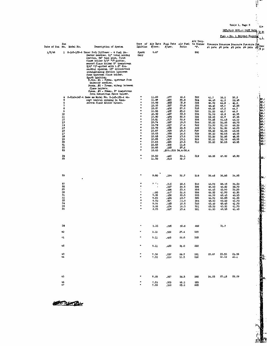
Tablo 1, Page 3
l87fldID BZ3 T=2 DA BI1
Fuel - No. I Solvent No tI 1Air Teip.
Run Typo of Mir Rate Fuel Rate Air Fuel to Burner Pressure Pressure Presoure Preaoure 16Date of Run No. Model No. Desription of System Ignitlon #/seo. 0/see. Ratio IF. ff psia J2 psia #3 pais #4 pain r si
1/3/46 1 2-IA3-13D-4 Inner Bc4y Diffuser - 4 fual in.- Spark 6.67 280gector needles. £I" total mixing onlysection, 54' tail pipe, firstflame holder 3/4" "Y"-gutter,second flame holder 6" downstream3/4" .Y"-gutter with 1.5" did.central opening, 13" cylindricalstraightening seootion upstreamfrom upstream flame holder.8 rk icnition.Pe.s #1 - Press. upstream frcinjector needles.
Press. #2 - Press. midway bftweenflame holders,
Proew, #3 - Preas. 3" downstreamfron downstream flame holoer.
4 2..A3-l0- Same as Model No. 2-L-13D-4 eox- 11.22 .277 to.6 302 41.7 38.2 37.55 oept central opening In down- " 11.00 .300 36.8 304 44.45 41.2 38.456 strewn flame holder closed. " 10.98 .363 .2.9 305 46.70 44.2 . C,7 10.93 .367 29.8 305 48.45 45.7 42.958 " 10.87 .400 27.2 305 49.95 47.2 44.7 ".9 " 10.83 .433 25.0 305 51.20 48.7 46.210 " 10.0 .467 23.2 306 51.70 49.2 46.9511 " 10.80 .484 22.3 306 52.20 49.7 47.4512 " 10.81 .517 20.9 306 52.95 50.45 48.2013 " 10.74 .567 19.0 306 53.20 50.95 48.70
14 " 10.72 .617 17.4 302 53.70 51.20 49.20
15 " 10.70 .650 16.5 308 53.70 51.20 49.20 9.:16 " 10.67 .700 15.2 307 53.20 50.95 48.9517 " 10.65 .750 14.2 309 53.20 50.95 48.9518 " 10.65 .784 13.6 309 53.20 50.95 48.9519 " 10.65 .817 13.1 309 53.20 50.70 48.95 48.20 " 10.65 .866 12.3 310 53.20 50.95 48.95
21 " 10.65 .900 11.822 " 10.65 .283 37.6
23 " 10.65 .277-.310 34.4-38.4
24 10.60 .440 24.1 319 49.95 47.20 45.2025 " 11.20 .518 21.7
26 9.00 .294 M0.7 318 39.45 36.95 34.95
27 - '- .316 28.6 310 40.70 38.45 36.2026 " .367 24.5 309 42.95 40.20 38.7029 .384 23.4 308 43.45 40.70 39.2030 . .00 .417 21.6 306 44.20 41.70 40.2031 " 9.02 .450 20.5 305 44.70 42.45 40.9532 9.03 .484 18.7 305 44.70 42.95 41.2033 9.03 .53. 26.9 304 45.20 43.20 41.70 .34 9.04 .>3 15.5 302 45.20 43.45 41.7035 9.02 .634 14.3 301 45.20 43.20 41.7036 8.95 .667 13.4 301 44.95 42.95 41.45
38 9.35 .282 33.0 282 31.7
40 9.11 .333 27.4 283
41 " 9.11 .400 22.0 283
42 " 9.11 .433 21.0 283
43 7.38 .257 28.7 281 23.67 22.55 21.96
4-4 " .32 .202 26ZS ZC.9o.0.
45 " 7.55 .267 28.3 282 24.25 23.18 22.29
46 " 7.55 .300 25.2 283
47 7.55 .300 25.2 283
II
"3Ie 1, Page 3
BT LiATA k
t- 1 Solvent Naph RatioE1ped renta
adure Air Sp. to Theoreticalp ae ressure Pressure Pressure Pressure Thrust Sp.Thrust Efficiency Impulse ieal Air
-' pase #4 pain J5 peia 06 pain i '/#/ceo. % i/R/seO. Sp. Impulse Notes and ComtenteUax. Air Rate et whichignition could be ob-teied. Narrow Air
Fuel linits. lanitionwas obtained at very
low air rates.
systtmPress. wropO-lca. fromTheoretical621 Press.ULasuraeents
pai
.5 618 2230 73.3 5.8U.45 698 2580 78.5 5.75
774 2325 82.5 5.443.95 82 2265 FK5.4 5.2544.7 876 2190 84.0 5.154$.2 916 2115 83.8 5.10.95 935 2000 82.0 4.6 Rates sat, then47.45 952 1965 81.5 4.9 spark thrown on4.20 994 1885 80.2 4.85 to teat ignition.48.70 987 1740 77.5 4.700p.2 0 95 1615 75.2 4.849.20 993 1530 73.5 4.98.95 989 1415 71.0 4.55.95 9b9 1320 69.4 6. b
48.95 985 1255 68.0 4.7.95 V80 1200 69.2 4.8
S48.95 985 1135 71.5 4.65
Lost Ignition-Rich LimitNo Ignitiou
Lean Iguition obtained at9 Continuous Buraing 34.4 and lost at Z8.4.20 879 2000 84.0I
Sputtered for onenminutebefore taidng hold. Sel1flame started in upstreamfiame holder %ben saprk wasthrown on, but full iezi-tion could not be obtained.
.95 619 2105 89.2 Lean ignition obtained at
A/? 30.6 and lost at A/P39.4.
6.20 644 2040 88.0.70 691 1885 85.5
9.20 699 1820 83.9 Continuous Burning Rough Burning.20 720 1725 81.8.95 742 1650 79.11
S1.20 750 1550 77.51.70 767 1435 75.2.70 771 1320 72.1 I
1.70 771 1215 69.6.45 750 1120 66.7 Lost Ignition-Rich Limit
Thrust, 3p.oifio Thrust andEfficiency slightly lowsirne calculated trom pres-aura downstream from down-
stream flame holder.Sputtered for about a ninute
before obtalning full ignition.Sputtered several seconds,
luel Rates set, is- then ignited.nited with spark. Snall flame in upstream
flame holder but no co-plate ignition.Small f.am in upstreamflaw holder but no com-plet* ignition.
I0.t 304 1510 81.1 bn intion obtained at A/1Y0 8.7 and lost at A/Y 36.5.
Thrust, Specific Thrust andZffioienoy slightly lowsince calculated from pres.sure downstream from down-stream flame holder..29 455 1705 83.5 ooth burning once burn-lug was obtained.
Very rough near rich limit.Shutting fuel out of centerinjection needle d11 notU'prove operat ion.
PVN 4176
I; -.-
Tabll
DETAILEDI)Fuol - No.
Air Temp.
Run Type of Air Rate Fuel Rete Air Fuel to Burner Pressure Pressure
Date of Run No. Model No. Description of System I6nition #/seo. d/sec. Ratio *F. #1 psia #2 pain
1/4/46 2 2-1A3-14D-4 Systen is s1.e as above, pressure 2.87 275 15.17 14.73 1 i3 Columns are as follows: 4.00 273 15.61 14.89 1
4 Press. #1 - Pr,ess. upstream from 5.35 274 16.33 14.98 15.17
5 injection nedles. 6.69 276 17.59 15.28 15.61
6 Press.02 - Press. midwa/ between 8.0 282 19.52 16.13 16337 flame holders. 9.18 287 22.06 17.93 17.59
8 Press.#3 - Press. 3" downstream 10.31 290 24.99 20.24 9.529 from flame holder. 11.13 290 26.00 21.90 2
10 Press. ,4 - Press. 9" downstream l.2 85 27.20 22.1 24.II from flaen holder. 11.57 134 27.69 22.01 26.99
12 Press. #' - Press. 23" downstream 11.93 284 28.38 23.16
13 from flame holder. 12.05 25 28.62 2J. 27.
Press. d6 - Press. 35" doswtreo 27.6
from fl -.:e holder. 28.62
1/4/46 2 2-1A-13-4 Sao description of this system above. 3.08 284 15.1 14,73 Pressure colu'ns are as follows: o.37 285 lb.08 14.721
4 Press. #I - Press. u',strm fro: 8.03 290 15.71 14.405 inject or needles. 9.40 294 2i.20 1011.
6 Press. j2 - Press. midwa,- between 10.36 295 23.62 10 .l .717 flane holders 10.25 295 25.20 17.57 21.20
8 Press. #3 - Press. 3" acwstrext, 11.82 296 26.40 18.45
9 fro doustresm fl.o holder. 12.00 296 26.00 18.8:2p 2
12 Press. 44 - -ress. 9" donstre Spark 6.56 300
from downstream flare holder. Only
Press. #5 - Press.23" dcwnstream
fron downstream flens holder.Press. #6 - Pross.35" downstreamfrom downstream flame holder.
1/4/46 1 2-IAS-15D-4 Inner Body Diffuser - 4 fuel in-. 2.80 296 14.72 14 62
2 Jector neeles, 21" mixing 3.97 293 14.71 14. VJ
3 seotion, 54" tal pipe, first 5.20 293 15.18 l. 30 4.72
4 flns holder 3/4" "'Y-euttor, 6.63 295 16.07 13.7. 4.71
5 second flo holder 6" downstream 7.99 298 10.10 Ii.M 8 18
6 1" "Y"-guttor .ith I.5" die. 9.11 300 k0.44 11.05 6.07
7 central opening closed. Spark 10.11 300 22.72 9.45
8 init)on. 10.33 302 23.27 8.75 0
9 Press. #1 - Press. midway between 10.82 304 24.40 6.25 .
10 flame holders. 11.85 305 26.57 6 W 2.72
11 Prems.t2 - Press. 3" donstrem 11.95 305 27.20 696
from downtream flame holder. 4.40
Press.3 - Press. 9" downstream 6.57
from downstream iflane holder. 7.20
Presa.v4 - Press.23" downstreamfrom dotnstream flame holder.
Press.#5 - Preos.35" (,ownstreamfrom downstream flame holder.
Press. #6 - Press. upstreamfrom i/ject;r noodles.
1/7/46 2 None.lA3- Sane as Model No. 2-1A3-15D-4 ex- 3.04 295 14.62 14.73
3 15D-4 capt no diffuser (inner oody 4.76 292 14.42 14.92
4 removed). 6.17 289 14.03 15.51
5 Pressure columns are also the 7.48 286 12.79 17.08 4.62
6 sane as listou for Lodel No. 8.85 286 15.88 4.64 14.01
7 2-1A-15D-4. 10.11 286 22.47 9.24 12.79
8 10.86 27 24.&5 6.79
9 1.18 290 24.82 6.96
10 1.55 292 25.57 7.16 47
12 Spark 10.90 .440 24.8 300 45.50 49.20 .82
13 " 1.85 .500 25.7 295
14 " 11.25 .610 18.5 293
15 " 11.08 See Notes 300
16 I.-.1 .440 25.3 295
17 " ...2 .5w. 2.2
10 11.12 .610 18.2
19 " 11.08 See Notes 300
1/8/46 1 2-.A'5-D-4 See description of B!urer 11.10 Hot Nocordou 297
No. O- S1 b so ,. o2 " 11.10 Not giecormod 297
3 " 11.10 Not tecorded 297 -
11.05 Son Notes 305
11.0- .440 25.2 300
AO .. i-h-A
B Table 1, Page 4
DETAILED BU--i 'MrZT DATA
Fuel - No. I Solvent Nauhtha
RatioExperimental
Air Sp. to TheoreticalPressure Pressure Pressure Pressure Pressure i reL,- ire Thrust Sp.Thrust Efficiency Lnp gse iceal - Air# psl #2 psia d3 psia #4 psia AS sin t6 ploa , #/W/soc. O li//sec. Sp. Implse % Notes and Co-mente
15.17 14.73 14.7 14.72 11.1 14.7115.61 14.89 14.69 14.72 1;.7 11.?16.33 14.98 14.66 14.73 14.7 11.717.59 15.28 1,..58 14.72 14.7 1-.7119.52 16.13 14.23 14.73 141.7 i1-7122.06 17.93 13.15 14.71 1"*.72 11.7324.99 20.24 10.83 14.91 1 i.'7 14.7926.80 21.90 4.14 13.16 14.74 14. ;.427.20 22.1b 4. q 1E.10 l-.73 14.8127.69 22.61 4.3. 5.60 14.47 14.7328.58 23.16 4.44 5.81 10.E8 14.40
28.62 23.37 4.,18 5.86 6.74 14.08
15.1 14.7 14.7 11.72 Ie.7 14.716.08 14.72 14.60 1..73 14.7 14.719.71 14.40 14.50 1,..74 14.69 14.721.20 15.01 13.6I1 14.0 14.72 14.7223.62 16.51 1.3.4. 14.89 14.0 14.7725.20 17.57 12.07 15.07 14.88 14.8026.40 18.45 8.4C 14.47 14.89 14.8426.60 18.82 i' ._4 I1 • 67 I1-.89 14.•65
Ignition coili ot bu ob-tainied above this airrate, thsOrn1"ir'..%nobservations of 1/3/.-,6on this burner.
14.72 14.62 14.70 14.7 14.71 15.1114.71 1.bO 14.71 11.70 14.71 15.695.18 14.30 !4.7E 114.70 14.7AL 16.6516.07 1 3.30 14.70 14.71 14.71 18.5c
i8.10 11.81 14.61 14.69 14.72 U,..44 i.0s 14.78 14.77 14.77 21.44
2.72 9.45 14.55 14.70 14.77 26.671.7 8.75 14.23 14.66 14.
75 27.93
4.40 6.25 5.42 14.34 11.60, 29.206.57 6.82 5.91 6.40 7.38 31.57
Ml.20 6.96 6.06 6.59 7.40 32.39
4.62 14.73 14.72 14.7 14.7 15.344.42 14.92 14.73 14.7 14.7 16.4S4.03 15.51 14.73 14.69 14.72 18.002.79 17.08 14., 14.69 14.72 20.73
15.88 4.64 14.75 14.74 14.75 24.132.47 9.24 14.39 14.70 14.74 27.464.25 6.79 5.76 11.02 14.36 29.804.82 6.96 5.89 6.44 13.31 30.33.57 7.16 6.05 6.64 9.83 31.153.50 49.20 52.80 864 2175 89.5 1 Air and Fuel Rates sot, Ignition after only a
then iLpited with fe seconds.
spark only. Smooth flano In upstreamflane holder but ralnportion of fuel did not
No flaro in upstreamiflano holder - no ignition.
Continuous Burning Full ignition at A/? ratio19.3 to 35.0. Smoothburnln o7, A/F ratio of22.9 to 32.3.
Three injection noodles Prompt ignitica.used. Air and fuel Full ignition after aboutrates sot, then Ig- 5 seconds.nited with spark only. Ver small flame in upstream
flame holder-no Ignition.Three injection needles Full ignition at A/F ratioused, 4 in. place - or 18.2 to 35.0. Smoothcontinuous burning, burning at A/F ratio of
22.9 to 30.9.Four injection needles Ignition after only a few
used. seconds.Air and fuel rates Smooth flame in upstreamsot, then Ignited flame holder but the main
> ;> ith spark only. portion of the fuel wasI I not ignited.
No flano in upstream flameholder - no Ignition.
Continuous burning. FuLL ignition at A/F ratioof 19.5 to 33.2. Smoothburning over A/F ratios of22.9 to 32.7.
Threo injection needles Prompt Ignition.usedf 4 In place.
PDN 4 1:6
'0
T
Table 1, P
UOTAILED BUW6tFue1 - No. 1 SolvWi
7Pros
Air Temp.Run Type of Air Rate Fuel Rate Air Fwil to Burner Pxesure Pressure Press
Date of Run No. Model No. Description of System Ignition #/sec. #/sec. Ratio *F. #1 psla #2 pale #3 ps
1/8/46 6 2-lA3-lb.-4 S , description of Burner Spark 11.08 .500 22.2 300 -
No. 2-LA3-15D-4 above. Only7 " 11.08 .610 18,1 300
" 11.10 See Notes 297
14.
141/9/46 1 2-1A3-1CD-4 Inner Body Diffuser - 4 fuel In- 2.80 291 14.68 14.64 14.7X .:
2 jector needles, 21" miing 4.78 289 14.72 14.50 14.7, 12.3 section, 54" tail pipe, first 6.53 290 14.91 14.17 14.72.'* 12.4 flane holder 3/4" "Y"-gutter, 7.63 291 15.44 13.78 14.73
' 8.
5 second flame holder 6" down- 9.20 295 17.46 12.94 14.66;6 stream I" "Y"-Iutter with 10.45 300 19.81 12.56 14.8.1 8.7 1.5" dia. central opening. 11.23 306 21.43 8.44 12.04 ' 44.8 Spark ignition. 11.63 309 22.16 8.75 6.42'9 Press. #1 - Press. milway be- 12.12 309 22.76 8.98 6.60'
12 tween flame holders. Spark 11.03 .440 25.2 299 47.7 44.0Press. #2 - Press. 3" down- Only
14 steam from downstrem flame " 11.38 .610 18.7 306holder.Press. j3 - Press. 9" downstraam
15 from downstream £1s€e holder. 10.46-10.71 308Press. #4 - Pres.23" downstreamfrcm downstrea. flame holder. 1/
PIess. #5 - Press.35" downstreamfrom downstream f'lamae holder.
Press. #6 - Press. upstream from
fuel injectors. 5136
17 " 10.75 .705 13.7 306 54.0 51.2018 11.19 .317 35.3 306 39.5 36:.4 4119 " 10.73 .666 16.1 306 53.4 50.7so " 10.80 .583 16.5 307 52.3 49.8
" 11.04 .367 30.1 307 44.7 41.5
" 11.30 .667 16.9 30744
511/10/46 2 2-2AZ-1OD-4 inner Body Diffuser - 4 fuel yen- " 10.85 .440 24.7 300 48.4 44.9
3 turie, 21" nixing section, 54" " 10.75 .500 21.5 :102 52.0 48.25 tail pipe, first flame holder " 10.68 .610 17.5 304 55.2 51.2
3/4"."YO-gutter, second flame6 holder 6" downstream 1" "Y"- " 10.67 .730 14.6 304
gutter with 1.5" dia. centralopening. Spark ignition.Press. #1 - Press. midway be-
twoon flame holders.Press. #2 - Press. 3" downstreamfrom downstream flane holder.
Press. #6 - Press. upstreamfro= venturis.
8 2-2A3-1D-4 Inner Body Diffuser - 4 fuel ven- 11.08turis, 21" mixing section, 54"tail pipe, first flame holder3/4" 1. -sutter, second flameholder 6 4cnstrem 1" "r"e-gutter with A.5" die. centralopening. 13" cylindricalstraightening section upstreanfrom upsv ram flame holder. 4Spark ignition. 4
1/14/46 3 2-2A3-lCD-4 . above. Pronuro colunn are: .440 24.9 297 49.0 45.0 52.6 r5 Press. #i - Press. midway be- 1 .560 1.9D 297 52.4 4 55.3
tween flame holrs. 10.65 .610 17.45 297
Press. J2 - Press. 3" downstreamfrom downstream flame holder.
Presb. #3 - Press. upstreafrom venturic.
Table 1, Page o
P I~ U5E 2TDZ
1I NO. -1 Solvent Naphtha
Ratio
1EperiventalAir Sp. to Theoretical
Pressure Preasurs Pressure Pressure Pressure Thrust Sp.Thruat Ifficienoy Impulse Iasl - Air#2 psia #3 pals e
4 p3ia #5 psaI 16 psia # #/#/seo. % #/#/se. Sp. Inpulae % Notes and Coents
JJ used. 4 in place. seconde.
-Air and fuel rates set, No flane in upstreamthen ignited .with spark flare holder - no igni-
J only. tion.Continuou3 burning. Full Ignition at A/? ratio
of 20.9
to 34.1. Smooth
burning over A/' ratio of22.2 to 31.0
14.64 14.71 14.7 14.7 15.0814.50 14.71 14.7 14.7 15.93 System
14.17 14.72 14.7 14.7 17.35 Press. Drop
13.78 14.73 14.7 14.7 19.18 Celod. from
1 2.?4 14.66 14.7 14.72 22.29 Theoretical
12.56 14.81 14.72 14.78 25.40 and Press.. 8.44 12.04 14.69 14.75 27.41 1easurements
8.75 6.42 14.11 14.66 29.07 psi
48 8.98 6.60 9.25 14.29 29.132 44.0 51.2 897 2040 83.0 130 90.2 5.7 Air Fuel RattO set, FW ignited after a few1 then ignited with seconds.i.601 J spark. Small unsteady flame in
upstream flame holder.No full Ignition.
Full Ignition over A/Fratio of 13.3 to 35.0.
Smooth burning over A/1ratio of 29.4 to 35.0;13.3 to 19.3.
Resonant over A/F ratio
of 19.3 to 27.9 -particularly bad 22.7to 25.4.
51.20 56.3 1075 1375 75.3 147 84.0 4.7 Smooth burning.36.4 43.5 684 2160 77.3 11 88.5 5.3 Smooth burning.50.7 55.7 1075 1610 80.3 148 88.4 4.1 Smooth burning. •49.8 55.0 1063 1825 84.7 146 91.9 3.7 'Looth burning.41.5 47.8 823 22ZO 85.7 123 92.0 4.8 Smooth burning.
Small unsteady flame in
upstream flame holder.no full ignition.
44.9 52.0 927 2110 87.1 136 91.4 U Air Fuel Rates se;, Prompt Ignition - smooth48.2 55.2 1032 2065 W. 144 0.4 then ignited with burning.51.2 58.1 1089 1785 85.2 151 92.9 zpark. Burning eooth after a
few seconds.Prompt igniton but verv
rough -urning.
No full ignjtion. Smallflame in upstream flameholder over A/P ratios of20.1 to 51.1.
45.0 52.6 945 2150 87.7 Air Fuel Rates set, Smooth burning.40.2 55.3 1020 2040 88.0 then ignited wlth Smooth burning.
6spar. Rough burning.
.3
PDN 4136
2 I
cm,
3 0 C
crl N N*4
CO.-4 0 %k0 co
tu qr 4 04 P :
Hw 0 4-)
** 0O +C3H0 +
o 414-'34-g
O 4,3 0 14035Cq-4 -4 3
p4"d
0 o 4+3 A4 R
P,:
4JN 4'
4 V-3 0C
CD PC 4a GH
vs i NJ0 0 n
00 W
'- 3 0 4 J
0 - r *0 4
0 cagoCD Cl4C
C3-4 H C 2CP4 4
4. r, z 3
;i+ -. -t $
A4j ~ c to~ 0 g
ecfV 4-' 3o 0 3 0 0 q.Oaka


![INDEX [] · Air Cleaners/Accessories ... Block Filler ... Thrust Buttons/Plates..... 62,192,201,206,361,385 Canopy, Pit](https://img.pdfslide.net/doc/110x75/5b206dd27f8b9a8e448b4c81/index-air-cleanersaccessories-block-filler-thrust-buttonsplates.jpg)