Embed Size (px)
Citation preview

FEL Conf., Daejeon, 08/2015 1 [email protected]
Estimate of FEL Gain Length in the Presence of
e-beam Collective Effects
S. Di Mitri1, S. Spampinati2
1Elettra Sincrotrone Trieste 2Univ. of Liverpool, Cockroft Inst.
FEL Conf., Daejeon, 08/2015 [email protected] 2
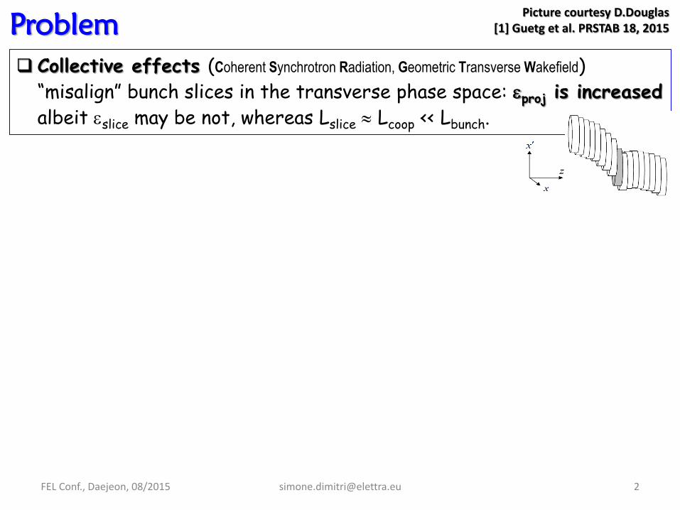
Problem
Collective effects (Coherent Synchrotron Radiation, Geometric Transverse Wakefield)
“misalign” bunch slices in the transverse phase space: proj is increased
albeit slice may be not, whereas Lslice Lcoop << Lbunch.
Picture courtesy D.Douglas [1] Guetg et al. PRSTAB 18, 2015

FEL Conf., Daejeon, 08/2015 [email protected] 3
Problem
Collective effects (Coherent Synchrotron Radiation, Geometric Transverse Wakefield)
“misalign” bunch slices in the transverse phase space: proj is increased
albeit slice may be not, whereas Lslice Lcoop << Lbunch.
This is the picture we have in mind:
Picture courtesy D.Douglas [1] Guetg et al. PRSTAB 18, 2015

FEL Conf., Daejeon, 08/2015 [email protected] 4
Problem
Collective effects (Coherent Synchrotron Radiation, Geometric Transverse Wakefield)
“misalign” bunch slices in the transverse phase space: proj is increased
albeit slice may be not, whereas Lslice Lcoop << Lbunch.
This is the picture we have in mind:
iproj ,
Picture courtesy D.Douglas [1] Guetg et al. PRSTAB 18, 2015
iprojfproj ,,
FEL Conf., Daejeon, 08/2015 [email protected] 5
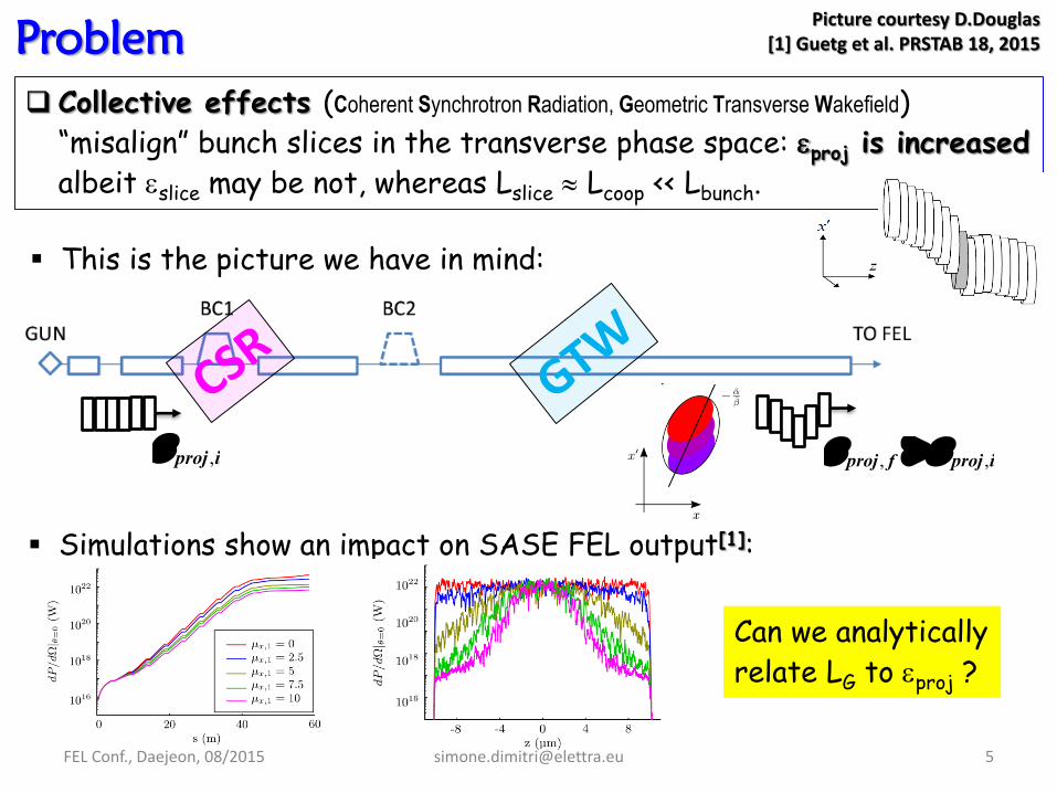
Problem
Collective effects (Coherent Synchrotron Radiation, Geometric Transverse Wakefield)
“misalign” bunch slices in the transverse phase space: proj is increased
albeit slice may be not, whereas Lslice Lcoop << Lbunch.
This is the picture we have in mind:
iproj ,
Picture courtesy D.Douglas [1] Guetg et al. PRSTAB 18, 2015
Can we analytically
relate LG to proj ?
Simulations show an impact on SASE FEL output[1]:
iprojfproj ,,
FEL Conf., Daejeon, 08/2015 [email protected] 6
Single Kick Error (Dipole-like)
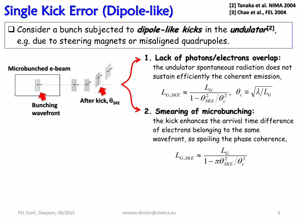
Consider a bunch subjected to dipole-like kicks in the undulator[2],
e.g. due to steering magnets or misaligned quadrupoles.
[2] Tanaka et al. NIMA 2004 [3] Chae et al., FEL 2004
Microbunched e-beam
Bunching wavefront
After kick, SKE
1. Lack of photons/electrons overlap: the undulator spontaneous radiation does not
sustain efficiently the coherent emission,
2. Smearing of microbunching: the kick enhances the arrival time difference
of electrons belonging to the same
wavefront, so spoiling the phase coherence,
22, 1 cSKE
GSKEG
LL
,1 22,
cSKE
GSKEG
LL
Gc L
FEL Conf., Daejeon, 08/2015 [email protected] 7
Single Kick Error (Dipole-like)
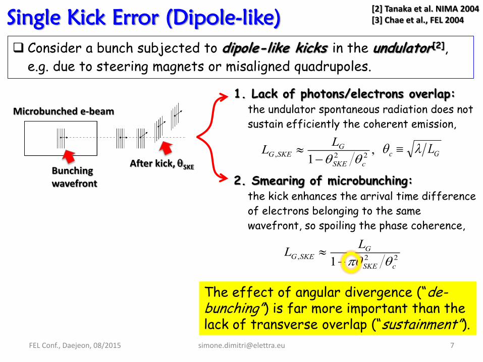
Consider a bunch subjected to dipole-like kicks in the undulator[2],
e.g. due to steering magnets or misaligned quadrupoles.
[2] Tanaka et al. NIMA 2004 [3] Chae et al., FEL 2004
Microbunched e-beam
Bunching wavefront
After kick, SKE
1. Lack of photons/electrons overlap: the undulator spontaneous radiation does not
sustain efficiently the coherent emission,
2. Smearing of microbunching: the kick enhances the arrival time difference
of electrons belonging to the same
wavefront, so spoiling the phase coherence,
22, 1 cSKE
GSKEG
LL
,1 22,
cSKE
GSKEG
LL
Gc L
The effect of angular divergence (“de-bunching”) is far more important than the lack of transverse overlap (“sustainment”).
FEL Conf., Daejeon, 08/2015 [email protected] 8
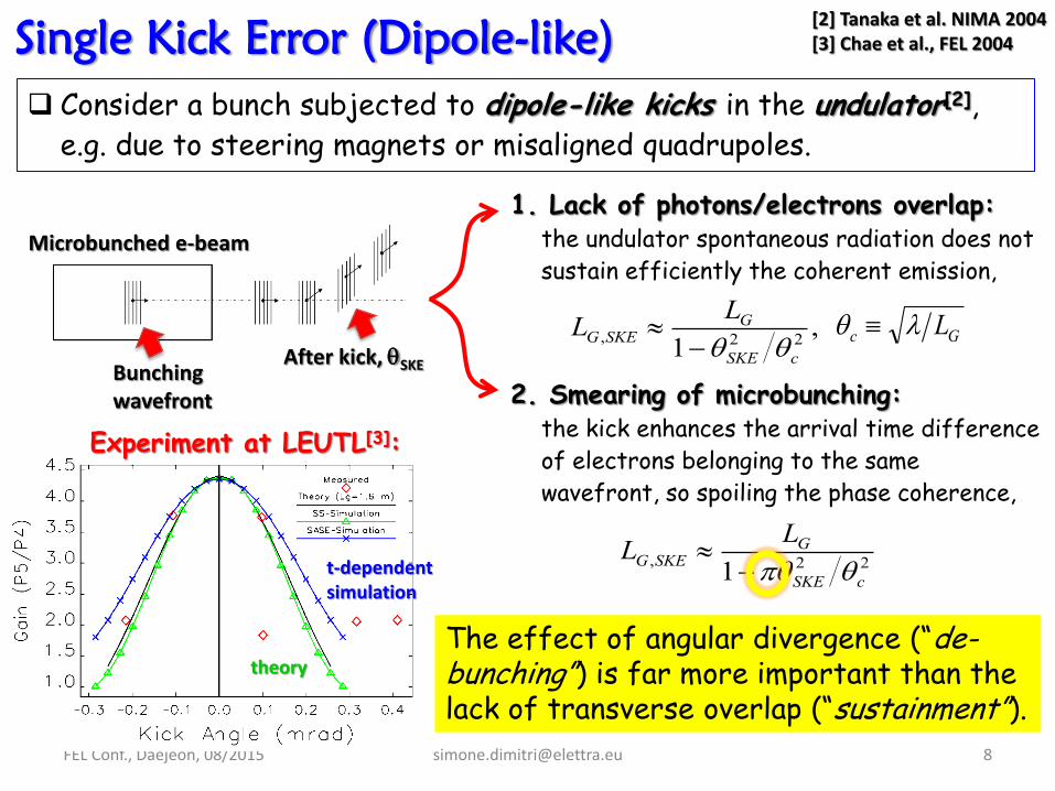
Single Kick Error (Dipole-like)
Consider a bunch subjected to dipole-like kicks in the undulator[2],
e.g. due to steering magnets or misaligned quadrupoles.
[2] Tanaka et al. NIMA 2004 [3] Chae et al., FEL 2004
Microbunched e-beam
Bunching wavefront
After kick, SKE
1. Lack of photons/electrons overlap: the undulator spontaneous radiation does not
sustain efficiently the coherent emission,
2. Smearing of microbunching: the kick enhances the arrival time difference
of electrons belonging to the same
wavefront, so spoiling the phase coherence,
22, 1 cSKE
GSKEG
LL
,1 22,
cSKE
GSKEG
LL
Gc L
The effect of angular divergence (“de-bunching”) is far more important than the lack of transverse overlap (“sustainment”).
Experiment at LEUTL[3]:
t-dependent simulation
theory

FEL Conf., Daejeon, 08/2015 [email protected] 9
We now consider error kicks that affect individual slices, e.g. from
CSR in a dipole, and from GTW in an RF cavity.
0,
2
0,0,
20,1,
'1'det
x
xx
xxx
xxxx
xx
Projected Emittance Growth
The “-matrix” provides an RMS estimate of proj induced by those
perturbations. For a single angular error (x’):
Consider the uncorrelated sum of m-consecutive CSR kicks in magnetic
compressors and GTW kicks in the linac. The resultant projected
emittance, e.g. at the undulator, turns out to be:
Twiss functions are at the location of the perturbation
...11
1,0,,
m
iin
infn P

FEL Conf., Daejeon, 08/2015 [email protected] 10
We now consider error kicks that affect individual slices, e.g. from
CSR in a dipole, and from GTW in an RF cavity.
0,
2
0,0,
20,1,
'1'det
x
xx
xxx
xxxx
xx
RMS kick averaged over all the slices.
Projected Emittance Growth
The “-matrix” provides an RMS estimate of proj induced by those
perturbations. For a single angular error (x’):
Consider the uncorrelated sum of m-consecutive CSR kicks in magnetic
compressors and GTW kicks in the linac. The resultant projected
emittance, e.g. at the undulator, turns out to be:
Twiss functions are at the location of the perturbation
...11
1,0,,
m
iin
infn P
We will evaluate
this later.
...11
1,,,
m
iin
iinfn P
FEL Conf., Daejeon, 08/2015 [email protected] 12
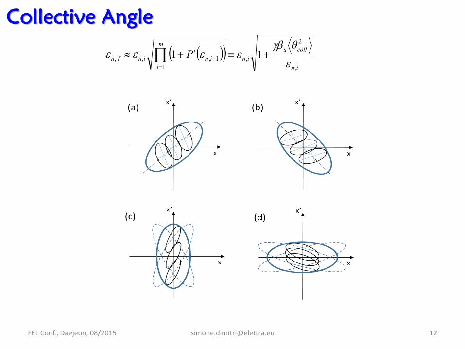
Collective Angle
in
colluin
,
2
, 1

...11
1,,,
m
iin
iinfn P
FEL Conf., Daejeon, 08/2015 [email protected] 13
Collective Angle
This is solely determined by the linac dynamics.
in
colluin
,
2
, 1
This is the resultant angular spread of the bunch slices’ centroids.
This is <> in the undulator.

...11
1,,,
m
iin
iinfn P
FEL Conf., Daejeon, 08/2015 [email protected] 14
Collective Angle
02 coll
In the UNDULATOR, if the beam is matched to a SMALL u, the slices are largely dispersed in angle:
02 coll
If the beam is matched to a LARGE u, the slices overlap in angle:
AFTER the kick(s), the slices follow different trajectories in phase space, but the projected emittance is preserved:
ctecoll 2
We expect a BIG impact on FEL gain
We expect a SMALL impact on FEL gain
This is solely determined by the linac dynamics.
In the LINAC, two slices are displaced along the direction of the kick.
The slice emittance is unperturbed, while the projected is enlarged.
in
colluin
,
2
, 1
This is the resultant angular spread of the bunch slices’ centroids.
This is <> in the undulator.

FEL Conf., Daejeon, 08/2015 [email protected] 15
3-D Gain Length
in
colluinfn
,
2
,, 1
22, 1 cSKE
GSKEG
LL
)],(1[ ,3, yxGDG LL
DGth L 3, ,1 22
3,,
thcoll
DGcollG
LL
We propose[7]:
[7] Di Mitri, Spampinati, PRSTAB 17, 2014
Single-slice dynamics
De-bunching
Projected dynamics

FEL Conf., Daejeon, 08/2015 [email protected] 16
3-D Gain Length
in
colluinfn
,
2
,, 1
22, 1 cSKE
GSKEG
LL
)],(1[ ,3, yxGDG LL
DGth L 3, ,1 22
3,,
thcoll
DGcollG
LL
We propose[7]:
[7] Di Mitri, Spampinati, PRSTAB 17, 2014
Single-slice dynamics
De-bunching
Projected dynamics
This depicts the SLICE dynamics
This depicts the PROJECTED dynamics

FEL Conf., Daejeon, 08/2015 [email protected] 17
3-D Gain Length
in
colluinfn
,
2
,, 1
22, 1 cSKE
GSKEG
LL
)],(1[ ,3, yxGDG LL
DGth L 3, ,1 22
3,,
thcoll
DGcollG
LL
We propose[7]:
[7] Di Mitri, Spampinati, PRSTAB 17, 2014
Single-slice dynamics
De-bunching
Projected dynamics
Theory vs. GENESIS simulations: 1) --- n,proj = n,slice = 0.5 m
2) --- n,proj = n,slice = 2.3 m
3) --- n,proj = 2.3 m > n,slice = 0.5 m
Intuitively, we expect LG of 3)
in between that of 1) and 2);
confirmed by simulations.
u := (<x><y>)1/2; the scan spans
different scenarios of radiation
diffraction.
E = 1.8 GeV
I= 3.0 kA
u = 2 cm
K=√2 = 0.1%
FEL = 1.6 nm
This depicts the SLICE dynamics
This depicts the PROJECTED dynamics

FEL Conf., Daejeon, 08/2015 [email protected] 18
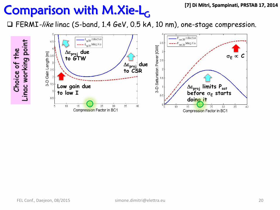
Comparison with M.Xie-LG
FERMI-like linac (S-band, 1.4 GeV, 0.5 kA, 10 nm), one-stage compression. C
hoi
ce o
f th
e
Lin
ac w
orki
ng p
oint
[7] Di Mitri, Spampinati, PRSTAB 17, 2014

Low gain due to low I
proj due to CSR
proj due to GTW E C
proj limits Psat before E starts doing it
FEL Conf., Daejeon, 08/2015 [email protected] 19
Comparison with M.Xie-LG
FERMI-like linac (S-band, 1.4 GeV, 0.5 kA, 10 nm), one-stage compression. C
hoi
ce o
f th
e
Lin
ac w
orki
ng p
oint
[7] Di Mitri, Spampinati, PRSTAB 17, 2014
Low gain due to low I
proj due to CSR
proj due to GTW E C
proj limits Psat before E starts doing it
FEL Conf., Daejeon, 08/2015 [email protected] 20
Comparison with M.Xie-LG
FERMI-like linac (S-band, 1.4 GeV, 0.5 kA, 10 nm), one-stage compression. C
hoi
ce o
f th
e
Lin
ac w
orki
ng p
oint
[7] Di Mitri, Spampinati, PRSTAB 17, 2014

CSR strength
GTW
str
en
gth
FE
L S
ens
itiv
ity
to L
inac
sett
ing
CSR strength
GTW
str
en
gth
CSR strength
GTW
str
en
gth
Bn,6D
LG,coll Psat,coll
Low gain due to low I
proj due to CSR
proj due to GTW E C
proj limits Psat before E starts doing it
FEL Conf., Daejeon, 08/2015 [email protected] 21
Comparison with M.Xie-LG
FERMI-like linac (S-band, 1.4 GeV, 0.5 kA, 10 nm), one-stage compression. C
hoi
ce o
f th
e
Lin
ac w
orki
ng p
oint
[7] Di Mitri, Spampinati, PRSTAB 17, 2014

CSR strength
GTW
str
en
gth
FE
L S
ens
itiv
ity
to L
inac
sett
ing
CSR strength
GTW
str
en
gth
CSR strength
GTW
str
en
gth
Bn,6D
LG,coll Psat,coll
Low gain due to low I
proj due to CSR
proj due to GTW E C
proj limits Psat before E starts doing it
FEL Conf., Daejeon, 08/2015 [email protected] 22
Comparison with M.Xie-LG
FERMI-like linac (S-band, 1.4 GeV, 0.5 kA, 10 nm), one-stage compression. C
hoi
ce o
f th
e
Lin
ac w
orki
ng p
oint
[7] Di Mitri, Spampinati, PRSTAB 17, 2014
5-D BRIGHTNESS vs. COMPRESSION FACTOR
FEL Conf., Daejeon, 08/2015 [email protected] 23
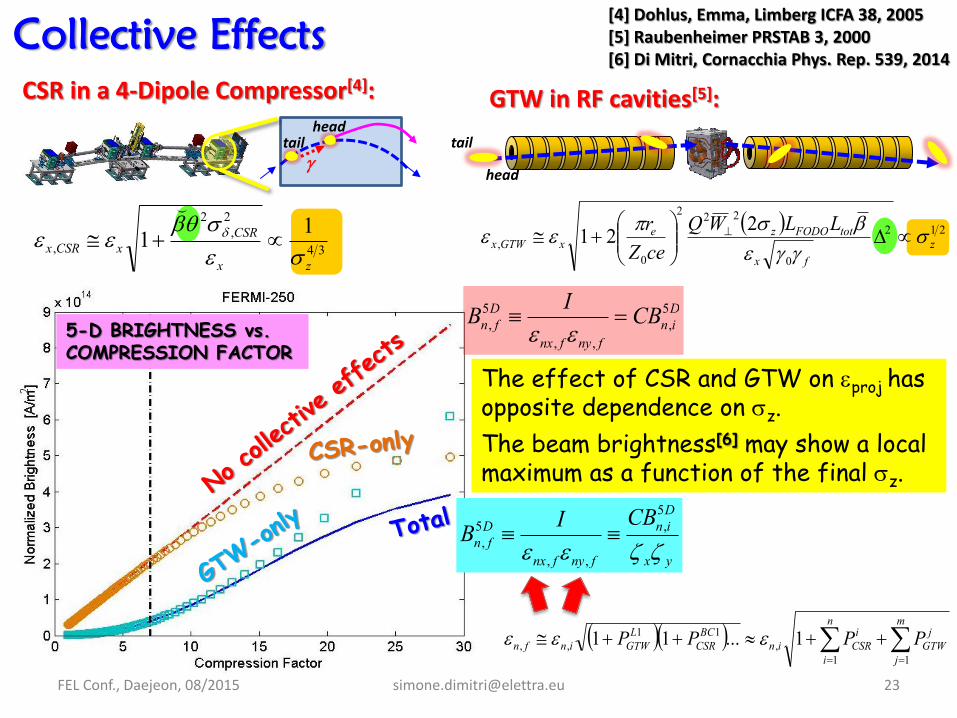
Collective Effects
tail head
CSR in a 4-Dipole Compressor[4]: GTW in RF cavities[5]:
yx
Din
fnyfnx
Dfn
CBIB
5,
,,
5,
[4] Dohlus, Emma, Limberg ICFA 38, 2005 [5] Raubenheimer PRSTAB 3, 2000 [6] Di Mitri, Cornacchia Phys. Rep. 539, 2014
head
tail
The effect of CSR and GTW on proj has opposite dependence on z.
The beam brightness[6] may show a local maximum as a function of the final z.
m
j
jGTW
n
i
iCSRin
BCCSR
LGTWinfn PPPP
11,
11,, 1...11
212
0
222
0,
221 zfx
totFODOzexGTWx
LLWQceZr
34
2,
2
,11zx
CSRxCSRx
Din
fnyfnx
Dfn CBIB 5
,,,
5,

FEL Conf., Daejeon, 08/2015 [email protected] 24
Conclusions
LG,coll aims to include the beam projected dynamics. A deviation 10%
was found vs. 3-D time-dependent simulations, over a wide range of u.
When proj > slice, a considerable deviation from M.Xie-LG appears.
This suggests a larger u for optimum FEL performance.
The model can be used either for tuning of the accelerator in order
to maximize the FEL performance, or for specifying the FEL tolerance
on the beam projected emittance, vs. the undulator optics.
Further numerical studies will assess the limits of the proposed model:
<2coll> neglects correlations between consecutive CSR and GTW kicks.
the “-factor” in LG,coll might actually depend on e-beam parameters.
Psat and Lsat were re-scaled to the 1-D model.

FEL Conf., Daejeon, 08/2015 [email protected] 25
Acknowledgements
A special thank to my collaborator, S. Spampinati
W. Fawley and E. Allaria are acknowledged for instructive
discussions and suggestions.
This work was funded by the FERMI project of Elettra Sincrotrone
Trieste.
Thank You for Your attention


![Owner Cost Estimate Reviews - Cost · PDF file4 Estimate Review by Estimate Classification AACE International (AACE) Recommended Practice No. 18R-97 [1] outlines the Cost Estimate](https://img.pdfslide.net/doc/110x75/5a716d007f8b9aa2538ce01e/owner-cost-estimate-reviews-cost-engineeringwwwicosteorgwp-contentuploads20100992final-paper-icec-2pdf.jpg)