Embed Size (px)
Citation preview
1
ESTUARINE AND COASTAL SEDIMENTATION PROBLEMS1
Leo C. van RijnDelft Hydraulics and University of Utrecht, The Netherlands. Email: [email protected]
Abstract: This Keynote Lecture addresses engineering sedimentation problems in estuarine and coastalenvironments and practical solutions of these problems based on the results of field measurements, laboratoryscale models and numerical models.The three most basic design rules are: (1) try to understand the physical system based on available field data;perform new field measurements if the existing field data set is not sufficient (do not reduce on the budget forfield measurements); (2) try to estimate the morphological effects of engineering works based on simple methods(rules of thumb, simplified models, analogy models, i.e. comparison with similar cases elsewhere); and (3) usedetailed models for finetuning and determination of uncertainties (sensitivity study trying to find the mostinfluencial parameters).Engineering works should be designed in a such way that side effects (sand trapping, sand starvation, downdrifterosion) are minimum. Furthermore, engineering works should be designed and constructed or built in harmonyrather than in conflict with nature. This ‘building with nature’ approach requires a profound understanding ofthe sediment transport processes in morphological systems.Keywords: Sedimentation, sediment transport, morphological modelling
1. INTRODUCTIONThis lecture addresses sedimentation and erosion engineering problems in estuaries andcoastal seas and practical solutions of these problems based on the results of fieldmeasurements, laboratory scale models and numerical models.Often, the sedimentation problem is a critical element in the economic feasibility of a project,particularly when each year relatively large quantities of sediment material have to be dredgedand disposed at farfield locations.Although engineering projects are aimed at solving problems, it has long been known thatthese projects can also contribute to creating problems at other nearby locations (side effects).Erosion often occurs in places where sediment cannot be supplied by nature in sufficientquantities because it is trapped in another part of the system. The trapping can be due tonatural causes or due to manmade changes in the system. Dredging of ship channels,construction of jetties, groynes and seawalls always results in the redistribution of sand withinthe local system. Engineering works should be designed in a such way that side effects (sandtrapping, sand starvation, downdrift erosion) are minimum. Dramatic examples of side effectsare presented by Douglas et al. (2003), who state that about 1 billion m3 (109 m3) of sand areremoved from the beaches of America by engineering works during the past century.Nourishment and bypassing of sand are often required to mitigate the inavoidable sideeffectsof engineering works. It is important to emphasize that engineering works should be designedand constructed or built in harmony rather than in conflict with nature. This ‘building withnature’ approach requires a profound understanding of the sediment transport processes inmorphological systems (Van Rijn, 2005).
2. SEDIMENTATION PROBLEMS
Human interference in hydraulic systems often is necessary to maintain and extend economicactivities related ports and associated navigation channels. In many situations engineeringstructures are required to stabilize the shoreline, shoals and inlets, to reduce sedimentation, toprevent or reduce erosion, or to increase the channel depth to allow larger vessels entering theharbour basin. Coastal protection against floods and navigability are the most basic problems inmany estuaries in the world.
1 International Journal of Sediment Research, Vol. 20, No. 1, p. 3951

2
Examples of engineering works in estuaries and coastal systems are shown in Figure 1.
Figure 1 Examples of manmade structures in river, eastuary and coastal systems
Sedimentation problems generally occur at locations where the sediment transporting capacityof the hydraulic system is reduced due to the decrease of the steady (currents) and oscillatory(waves) flow velocities and related turbulent motions. Examples are: the expansion of the flowdepth and width due to natural variations or artificial measures (dredging), the presence ofvortex or eddy zones, flow separation zones, dead water zones and lee zones of structures.Expansions of the navigational depth will reduce velocities inducing shoaling. Similarly, theexpansion of the width of turning and mooring basins inside a harbour area will reducevelocities stimulating shoaling conditions. Piers or piling structures create eddies resulting inincreased shoaling.Sedimentation problems are most often associated with human interference in the physicalsystem such as the construction of artificial structures or the dredging of sediment from thebed to increase the flow depth or width. However, sedimentation (as well as erosion) also is abasic phenomenon of nature dealing with loose sediments within the transporting cycle fromsource to sink locations. Natural sedimentation areas are known as shoals, flats, banks, sheets,bars, etc. Human interference in these natural sedimentation areas will always lead torelatively large maintenance cost and should therefore be avoided as much as possible.
Sedimentation problems in estuaries and coastal seas are herein classified, as follows:
Channel sedimentation Basin sedimentation Shoreline sedimentation1) Navigation channels;2) Inlet channels;3) Entrance channels ofharbours, docks and waterintakes;4) Trenches for tunnels,pipelines and cables;
1) Harbour and port basins,Docks2) Open settling basins, turningand mooring basins, mining pits3) Water intake basins;4) Flood plains and reservoirs.
1) Updrift area of groynes andbreakwaters normal to shore;2) leeside area of offshorebreakwaters parallel to shore.
Shoal
Reservoir
Groynes
Training wall
Harbour
Navigation channel
Jetty
Waves
Tidal flow
River flow
Offshorebreakwater
Waves

3
2.1 Navigation channelsPorts are of vital importance for the economy of coastal countries. The increasing draft ofvessels requires the dredging of deepdraft channels connecting the port to deep water.Generally, these channels suffer from sedimentation requiring mainenance dredging to ensuresafe passage of the ships under most conditions. The costs related to capital and maintenancedredging often are critical in the economic functioning of ports. Therefore, the channel shouldbe designed in such a way that sedimentation is minimum.When the flow passes a channel, the velocities decrease due to the increase of the waterdepths in the channel and hence the transport capacity of bed load and suspended loaddecreases. As a result the bedload particles and a certain amount of the suspended sedimentparticles will be deposited in the channel (see Figure 2).
Figure 2 Channel sedimentation (plan view and crosssections)
When waves are present, this process is considerably enhanced due to the sediment stirringaction of the wave motions in the nearbed region resulting in larger sediment concentrations,which are subsequently transported by the flow.Factors enhancing sedimentation, are:· deep and wide channel;· orientation almost normal to the flow;· strong flows and large waves passing the channel;· fine sediment (fine sand and mud);· alignment through shoaling areas.Natural navigation channels in estuaries often suffer from the generation of bars/shoals at thetransition of flooddomiated and ebbdominated channels.
UNIDIRECTIONAL FLOW
TIDAL FLOW
Bed level at time T
FLOW
PLAN VIEW OF CHANNEL

4
2.2 Inlet channelsNatural tidal inlet channels generally suffer from heavy sedimentation due to waveinducedlongshore input of sediments thereby reducing the navigability of the channel. Jetties (longdamlike structures) are commonly build to eliminate the input of sediment by the longshorecurrent, creating an inlet channel (see Figure 3). The jetties should be so long that thesedimentation at the entrance of the channel due to longshore bypassing of sediments isminimum. Sediment accumulation will generally take place on the updrift side of the jetties anderosion on the downdrift side. Mechanical bypassing of sediment may be required to reducedowndrift erosion.
Figure 3 Sedimentation of inlets, entrances and intakes (plan view)
Jetty design requires the following considerations to reduce sedimentation:· the length of the jetties should extend beyond the littoral transport zone;· the jetty spacing should be narrow, but not leading to excessively large channel velocities
undermining the jetties (wide jetties may lead to shoaling and meandering of the channel);· the jetties should be impermeable to prevent lateral passage of water and littoral
sediments;· the jetties should be parallel, rather than curved or tapered (narrow entrance, channel
widening); parallel jetties tend to confine the ebb flow, raising ebb velocities and therbyflushing sediment out of the channel into the sea;
· three jetties creating two parallel channels, may be build to separate the inlet channel fromthe river outflow;
· a settling basin/trap may be dredged at the entrance of the channel as a bufffer forsedimentation to ensure navigability of the channel.
Tidal flow
Jetties
Tidal flow
HARBOUR ENTRANCE
TIDAL INLET CHANNEL
WATER INTAKEINLET
Tidal flow
DOCK ENTRANCEINTAKE INLET
Flow

5
2.3 Entrance channels of harbours, docks and water intakesThe entrance to a harbour basin, dock or water intake basin generally suffers fromsedimentation due to the reduction of flow velocities and wave activity (see Figure 3). Often, acirculation cell is generated in the entrance of the basin due to the geometry involved, whichattracts sediments by exchange processes with the main flow system outside the entrance. Thebreakwaters should be streamlined or training walls may be built to reduce eddies and deadwater areas. Harbour entrances should never be built on the inside of bends, where naturalshoaling processes (point bars) generally occur.
Figure 4 Deposition patternsTop: River flow; deposition (point bars) near inner bend; erosion (pools) near outer
bendBottom: Tidal flow; deposition (flats) near inner channel bends and between channels
(shoal)Entrance design requires the following considerations to reduce sedimentation:· the entrance should not be located in shallow depth on the inside of a bend or close to
other natural shoaling areas (see Figure 4);· the entrance should be narrow and streamlined to reduce the generation of eddies, and
circulation zones;· the breakwaters should be impermeable to prevent lateral passage of water and sediments;· a settling basin/trap may be dredged at the entrance of the channel as a buffer for
sedimentation.
River inflow
Shoalinflo
Flatinflo
EbbFlood
Ebb Flood
Propagation of tidal wave
Point bar(shallow area)
Point bar
Pool(deep area)
Pool
Bar
A
Crosssection A
Thalweg
6
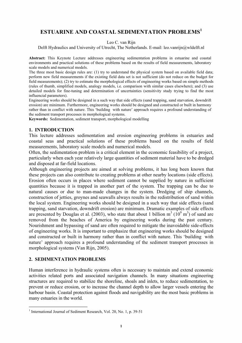
2.4 Trenches for tunnels, pipelines and cablesSmall scale trenches for pipelines and cables (Figure 5) are characterised by relatively smalldimensions; width of about 2 to 10 m and depth of 1 to 2 m, while the side slopes may be rathersteep (1 to 3), depending on soil conditions. These trenches generally have a triangular shapedue to the construction method (plowing). The depth of such a trench often only is a fraction ofthe water depth resulting in flow separation and the generation of vortex cells inside the majorpart of the trench area. In mobile bed conditions (surf zone near beach) the trench should havea considerable overwidth to serve as a buffer for sediment trapped in the period betweentrenching and pipe/cable laying.Tunnel trenches have dimensions similar to those of navigation channels and show the samesedimentation patterns.
Figure 5 Trenches for pipelines, cables and tunnels
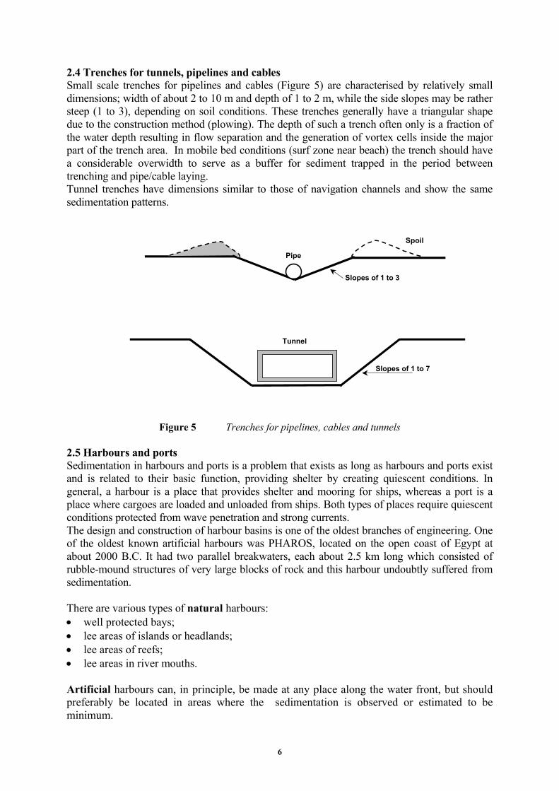
2.5 Harbours and portsSedimentation in harbours and ports is a problem that exists as long as harbours and ports existand is related to their basic function, providing shelter by creating quiescent conditions. Ingeneral, a harbour is a place that provides shelter and mooring for ships, whereas a port is aplace where cargoes are loaded and unloaded from ships. Both types of places require quiescentconditions protected from wave penetration and strong currents.The design and construction of harbour basins is one of the oldest branches of engineering. Oneof the oldest known artificial harbours was PHAROS, located on the open coast of Egypt atabout 2000 B.C. It had two parallel breakwaters, each about 2.5 km long which consisted ofrubblemound structures of very large blocks of rock and this harbour undoubtly suffered fromsedimentation.
There are various types of natural harbours:· well protected bays;· lee areas of islands or headlands;· lee areas of reefs;· lee areas in river mouths.
Artificial harbours can, in principle, be made at any place along the water front, but shouldpreferably be located in areas where the sedimentation is observed or estimated to beminimum.
Pipe
Spoil
Tunnel
Slopes of 1 to 7
Slopes of 1 to 3

7
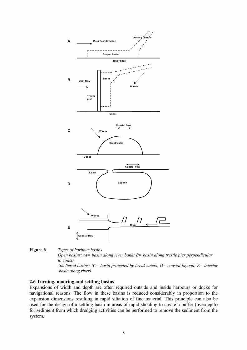
Artificial harbour basins can be classified into:· open basins; basins or berthing places which are open to flow and/ or waves; these basins
can be situated in nearshore coastal areas and along river banks, see Figure 6; the basingenerally is substantially deeper than the surrounding area so that an acces channel isrequired for vessels to enter the basin; mooring is only possible in conditions with weakcrosscurrents and mild wave motions;
· sheltered basins (enclosed); these types of enclosed basins are typified by a singleentrance to reduce the flow and wave motion as much as possible; three subclasses can beidentified: coastal basin with a controlled entrance, generally consisting of twinarmedbreakwaters or jetties (Figure 6); the breakwaters may block the longshore sedimenttransport requiring sediment bypassing methods; eddies and turbulence may produced inthe entrance; a semienclosed basin is obtained when only one breakwater or jetty ispresent on the updrift side; coastal dredged lagoon with an uncontrolled entrance (Figure 6), which may migratealong the shore or may suffer from severe sedimentation due to waveinduced processesor may even be closed by waveinduced sedimentation during storms; the entrance maysuffer from migrating channels and bars; relatively strong currents may be present due totidal filling of the basin; entrance may also be controlled by jetties interior basin (docks) along esturial or river channels (Figure 6) and/or lakes; eddies aregenerally present in the entrance area, where sedimentation of silty and muddy materialsusually is maximum.
The most important and difficult part of a sheltered harbour basin is the entrance. Manyharbour entrances have been found to be difficult for ships to navigate owing to currents,waves and morphology (sedimentation).
In previous centuries many harbours suffered from heavy sedimentation threatening theeconomic functioning of the harbour. Some harbours deteriorated completely due to heavysedimentation in the entrance area of the basin. For example, the harbour of Amsterdam (TheNetherlands) located in the southwestern part of an inner sea (former South Sea) was one ofthe most powerful harbours in the world in the 16th and 17th centuries, but lost its dominatingposition due to problematic sedimentation processes which could not be solved at that time.Owing to better dredges, it is now possible to keep almost each harbour entrance at therequired navigation level, although this may be a financial burden on the economicperformance of a harbour suffering from heavy sedimentation.From observed sedimentation rates it can be concluded that harbour sedimentation in freshwater conditions is much less (factor 5) than in salt and brackish water conditions. Thegeneration of stratified flow with a clear salt water wedge is a well known phenomenon in thetidal zone of major rivers ( tidal volume about equal to fresh water volume over tidal period).The maximum silt and mud concentrations are generally found in the area where the edge ofthe salt water front is moving up and down the river channel. This zone where soft fluid mudlayers are formed due to deposition at slack tides (especially neap tides) is known as theturbidity maximum. Harbour basins should preferably be situated outside this zone to avoidthat the deposited fluid mud layers penetrate into nearby harbour basins.
8
A
B
C
D
E
Main flow direction
River bank
Main flow
Waves
Coast
Trestlepier
Access channel
Coastal flow
River
Waves
Coast
Waves
Coastal flow
Coast
Lagoon
Breakwater
Coastal flow
Deeper basin
Basin
Figure 6 Types of harbour basinsOpen basins: (A= basin along river bank; B= basin along trestle pier perpendicularto coast)Sheltered basins: (C= basin protected by breakwaters, D= coastal lagoon; E= interiorbasin along river)
2.6 Turning, mooring and settling basinsExpansions of width and depth are often required outside and inside harbours or docks fornavigational reasons. The flow in these basins is reduced considerably in proportion to theexpansion dimensions resulting in rapid siltation of fine material. This principle can also beused for the design of a settling basin in areas of rapid shoaling to create a buffer (overdepth)for sediment from which dredging activities can be performed to remove the sediment from thesystem.

9
Figure 7 Shoreline accretion and erosion near coastal structures (plan view)
2.7 ShorelinesShorelines may suffer from largescale and smallscale sedimentation and erosion processes.Structures such as groynes or breakwaters perpendicular or oblique to the shoreline (Figure 7)will lead to sedimentation on the updrift side of the structure due to the blocking of thesediment transport (currentinduced and waveinduced transport of sediment). Similarly,sedimentation will occur in the lee of a shoreparallel breakwater (Figure 7). Generally,erosion will take place on the downdrift side, because the sediment transport will gradually
WAVES
OFFSHORE BREAKWATERENTRANCE INTAKE INLET
erosion
sedimentation
WAVES Flow
SEDIMENTATION AND EROSION NEAR INLET
WAVES
Flow
SEDIMENTATION AND EROSION NEAR GROYNES
erosion

10
restore itself eroding sediment particles from the downdrift side. Mechanical bypassing ofsediment may be necessary to deal with the downdrift erosion near structures.Large scale shoreline sedimentation and erosion generally are caused by:· episodic flood or storminduced processes;· obstruction of the sediment transport processes due to the presence of natural barriers or
artificial barriers;· fluctuations in sediment supply and transport;· onshore/offshoredirected sediment transport to or away from the shoreline;· mining/dredging and dumping of sediment.The available options to deal with typical erosion problems, are: (1) to accept retreat in areaswhere the shorelines/banks are wide and high; (2) to maintain the shoreline at a fixed position(by hard and/or soft structures or by dredging activities) and (3) to bring the shoreline forward byreclaiming land.
3 APPROACH OF THE SEDIMENTATION PROBLEMS
3.1 ApproachThe general approach to solve sedimentation and erosion problems consists of the followingmajor elements:1. Specification of the problem and definition of wider context (socioeconomic, legal,
political, environmental, administrative aspects, etc.).2. Formulation of general objectives and desired state of knowledge,
required level of accuracy, available time and budget.
3. Determination of problem dimensions and analysis of physical system (current state ofknowledge), relevant user functions, physical parameters of interest, space and time scales involved, state of the system (indicators). existing knowledge (literature, charts, interviews).
4. Formulation of hypotheses related to problem,5. Generation of alternative solutions and cost estimates,
selection and application of tools (existing databases, measurements/monitoring,models), application of specialist knowledge.
6. Selection of optimum solution.
The three most basic rules are:1. try to understand the physical system based on available field data; perform new field
measurements if the existing field data set is not sufficient (do not reduce on thebudget for field measurements);
2. try to estimate the morphological effects of engineering works based on simplemethods (rules of thumb, simplified models, analogy models, i.e. comparison withsimilar cases elsewhere);
3. use detailed models for finetuning and determination of uncertainties (sensitivitystudy trying to find the most influencial parameters).

11
3.2 Analysis of the physical systemOne of the most important activities within an engineering approach is a sound analysis of thephysical system considered, involving:· Geometry and scales of the system,
plan shape of coast, dimensions of shoals and bed forms, depths of natural channels, sediment composition and distribution, time scales of natural sedimentation and erosion patterns (migration rates), dredging volumes.
· Tides and currents, vertical tidal ranges (micro<1 m, meso1 to 4 m, macro> 4 m), peak current velocities of flood and ebb phases (incl. velocity profiles), duration and asymmetry of flood and ebb phases, penetration length into estuary, residual (tideaveraged) flow velocities, threedimensional flow patterns (flow in bends, stratified flow), winddriven currents.
· Sediment transport, bed forms (type and dimensions), mud, silt and sand concentration profiles, suspended size composition (sand), percentatages of mud and organic material, insitu settling velocities (for mud),
· Wave climate, dominant wind and wave direction, frequency and intensity of storms, types of coastal exposure (open, sheltered or exposed), presence of breaker bars.
· River discharge, frequency and intensity of flood waves, water levels and flow strenghts, presence of upstream control structures (weirs, barrages and reservors).
· Estuary phenomena stratification effects (salt wedge) near outlet, turbidity maximum (null zone), tidal flats and shoals (migration rates), flood and ebb channel crossings, tidal ebb delta and migrating mouth bars.
3.3 ToolsThe tools available for solving problems are:· existing databases,· measurements and monitoring (field studies),· numerical and or physical modelling.Field studies comprise:· Hydrodynamic measurements,
water level recordings, current velocity at fixed positions, current velocity profiling (ADCP method) from moving vessel, discharge measurements across main channels,

12
float trackings of curved streamlines, wave field close to shore.
· Sediment transport measurements, types and composition of sediment (mud, silt, sand, gravel, mixtures), critical bedshear stresses for erosion and deposition (mud), settling velocity (flocculation of mud), bed load transport in lowest 0.1 m of water column, sediment concentrations at various levels above bed, bulk density of bed material (consolidation of mud).
· Morphology, bathymetry as function of time, bed form trackings, sedimentation and erosion volumes from bathymetry data.
Laboratory scale models consist of:· Fixed bed engineering or design models,
tide levels and flow patterns, nearshore wave conditions, configuration of structures, strength of structures (breakwaters),
· Movable bed engineering models, valuable for smallscale 3D phenomena (local scour and deposition patterns), scale effects due to incorrect representation of sediment mobility and bed forms, laboratory effects due to space limitations and simplified boundary conditions,
· Process models, data for understanding of physics involved, data for calibration and validation of numerical models, systematic variation of parameters, immediate and repeatable results of experiments.
Mathematical models consist of:· 1 dimensional models (1D),
suitable for rivers and network system of ebb and flood channels in estuaries (nonstratified), suitable for longshore coastal flows, crosssectionintegrated equations, sediment transport capacity formulae, advantages: easy to apply, good results for tide levels and discharges, long termmorphology, disadvantages:poor results for local currents; no information of lateral morphology,
· 2 dimensionalvertical models (2DV), suitable for modelling of streamtubes (information of streamtubes from 2DH model), vertical structure of velocity and sediment concentration is included, space and time lag effects are included, advantages: easy to apply, operational on PC, long term estimates, disadvantages: schematization into streamtubes required, geometry of each tube mustbe known,
· 2 dimensionalhorizontal models (2DH), suitable for coastal seas and estuaries, depthaveraged mass and momentum equations in two horizontal directions,

13
depthaveraged suspended sediment equations (including lag effects), flooding and drying procedures, curvilinear grid for efficient computations, nesting of models for detailed computations, advantages: standard tool, operational on advanced PC, easy to combine with wavemodels, disadvantages: not for very irregular geometry, not for stratified flow, not forsecondary flow,
· 3 dimensional models (3D), mass and momentum in three coordinates (hydrostatic pressure is generallyassumed), curvilinear grid for efficient computations, advantages: all effects included (stratified and nonstratified flow, secondary flow),many details, disadvantages: not easy to apply (not much experience), only for local problems,short duration.
Sedimentation predictions can only be done accurately, if there is sufficient understanding ofthe physical processes based on field measurements. These types of measurements requireexperienced personnel to handle the sophisticated electronic instruments under extremeconditions and are often expensive to cover the long term natural variations of the hydraulicsystem considered. Fixed bed laboratory scale models can be operated to determine the localflow and wave fields; movable bed models may be applied to get information of local, smallscale morphological developments near structures. The results of these laboratory modelssuffer, however, from scale errors and interpretation errors related to the schematized boundaryconditions. Mathematical models donot suffer from scale effects, but the interpretation errorsdue to simplified model formulations and boundary conditions also limit the use of modelresults. Mathematical models are relatively easy to use but are not particularly cheap to operate,as many runs performed by experts are required to get a good feeling of the most importantparameters and uncertainties involved.
3.4 Mathematical models and guidelinesModels available for morphological predictions can roughly be divided into two groups:· Behaviouroriented models, including:
simple engineering rules, statistical models, equilibrium river regime models, equilibrium coastal profile models, advectiondiffusion type models, plan shape shoreline models,
· Processbased models, including: longitudinal river bed models, crossshore coastal profile models, network estuary models, area models (initial sedimentation/erosion, sequential morphodynamic models).
The applicability ranges of processrelated and behaviourrelated models are given in Table 1.
Behaviouroriented models have long been used in engineering practice. Many of thesemodels are however oversimplifications of complex systems that are poorly understood.

14
Illustrative arguments are: (1) poor assumptions and important omissions in modelformulations, (2) use of relationships of questionable validity, (3) crude representation ofboundary conditions, (4) incorrect model calibration and verification and (5) unknown modeluncertainties.
Profile and Area models are the two main generic types of processbased models. Bed levelchanges follow from numerical solution of the mass conservation balance.Profile models consider the physical processes in one (streamwise or crosssectionwise)direction, assuming uniformity in the other direction. The flood and ebb channels in an estuarysystem can be simulated by a network of 1D bed profile models.Area models are 2dimensional horizontal (or quasi 3dimensional) models consisting of, andlinking, a number of submodels describing the wave field, the tide, wind and wavedrivenflow field, the sediment transport fluxes and the bed evolution in a loop (feed back) system.Various numerical upscaling techniques are available to regularly extrapolate the morphologicalbed evolution from the computed bed levels at intermediate time steps. Using this upscalingtechnique (Rapid Assessment Method, RAM), the prediction horizon can be extended to about50 years.Fully 3Dmodels describing the currents on a threedimensional grid are in an early stage ofdevelopment, but the application possibilities of these models for realistic cases are rapidlyincreasing owing to improved computer technology.In any modelling approach, assumptions are being made regarding the natural system(alongshore uniform or not) and the physics included (sort of processes included and type ofsimplification). These assumptions limit the application of a model to specific spatial andtemporal scales.
SPATIAL ANDTEMPORALSCALES
STORMS MONTHSTOSEASONS
1 TO 5YEARS
5 TO 10YEARS
10 TO 100YEARS
0 10 KM
Coastal profilemodels
Areamodels (2DH)
Area models ((quasi) 3D)
Behaviouroriented
Coastal profilemodels
Areamodels (2DH; RAM)
models
10 100 KM River bed Network estuary
Behaviouroriented
models (1D)models (1D)
modelsTable 1 Applicability ranges of processrelated and behaviourrelated models
Basic questions for coastal managers are:· What type of model should be used (processbased or behaviouroriented model)?· When to select a Line model, Profile model or an Area model? Is the site considered
sufficiently uniform to warrant the use of a crossshore Profile model? Are morphologicalchanges due to rip currents important?

15
· What is the uncertainty in the model predictions? What is the bandwidth around thepredictions given all the possible values of free model parameters? How does the bandwidth(‘model variability’) compare to the natural variability in morphological change?
· What is the prediction horizon of the model? What are the most relevant time and spatialscales for modelling?
Model users should have a basic understanding of the main sources of model uncertainty,being:· errors in input data (schematization errors of past, present and future conditions),· errors in model formulations (model parameter settings, including processes not
modelled),· extrapolation errors using the model outside its validity range,· accumulation of errors through the simulation time.Various methods are available to quantify the uncertainties involved:· use local field data to validate the model for the problem considered and express the
results in objective statistical parameters and/or state indicators,· use multiple runs varying input data and model parameter settings (sensitivity runs),· identify worst case scenarios (most extreme extrapolation cases),· use probabilistic methods to present results in terms of mean values and standard errors at
a certain level of confidence.The model results should always be evaluated with respect to the natural variability of thephysical system at the relevant time and space scales involved. For example, the long termerosion of the coast may be relatively small, but the short term variability of the sand volumein the nearshore zone may be relatively large due to storm sequential effects. Modelpredictions of this parameter (sand volume in nearshore zone) are only meaningful if themodel variability (due to variation of model settings) is smaller than the natural variability.The selection of the most appropriate model approach for the problem at hand often is adifficult decision for the manager in charge, depending on many things such as: spatial andtemporal scales involved, available boundary data (bathymetry and hydrodynamics), accuracyand capability of existing models, available budget, etc. Models generally are in a certainstage of development and the model specialist always suggests to improve the model beforeactually applying it on the problem at hand. This dualism between model improvement by thespecialist and model application by the generalist can be overcome by making a ‘snapshot’evaluation of the existing model (see Figure 8).The ‘snapshot’ of what a model in its present state can do, first of all helps model users(modellers) to show how a model study should be set up, what data are required and how theresults can be usefully interpreted. Secondly it will identify the (un)certainties in the modelpredictions. This helps the modellers to identify strengths and weaknesses of their models andto suggest future improvements. It also helps the coastal managers to see how the modelresults can improve their understanding of the system. The model results should be presentedin terms of relevant State Indicators (SI’s). Morphological data should be as much as possibleaggregated to bulk volumes in relevant zones. In an ideal situation, a model prediction ofrelevant aspects of a pilot case should be made at the beginning of the project, with the meansthen available including estimated (un)certainties. At the end of the project a similarprediction should be made with the hopefully improved means (better model, better boundarydata based on additional measurements).The achieved reduction of the uncertainties (or possibly their improved estimation) could be ameasure of the project’s success.

16
Figure 8 Evaluation of enduseroriented model development
Guidelines for model application are:· select relevant State Indicators, such as:
characteristic current velocities; focus on low tide for maximum currents; characteristic bed levels, water depths at specific locations bulk sand volumes in selected zones (precise bed levels cannot be simulated accurately);
· use standard settings for initial runs;· apply additional calibration of model settings using measured bathymetry (if available) for
storm, seasonal and decadal time scales;· apply sensitivity computations to estimate the effects of model settings and input wave/
current/sediment conditions; identify worst case scenarios; select appropriate time scales;· use probabilistic methods to present results;· evaluate results in comparison with natural variability;· use appropriate safety margins.
ACKNOWLEDGEMENTSDelft Hydraulics is gratefully acknowledged for providing the means to compose this Keynote Lecture and toparticipate in the Nineth International Symposium on River Sedimentationin in Yichang, China.
REFERENCESDouglas, S. et al. 2003. The amount of sand removed from America’s beaches by engineering works, Coastal
Sediments, Florida, USAVan Rijn, L.C., 2005, Principles of Sedimentation and Erosion Engineering in Rivers, Estuaries and Coastal Seas,
600 p., incl. toolkit on CDROM. Aqua Publications (WWW.AQUAPUBLICATIONS.NL), The Netherlands
Modellers
End users
Scientists
‘Snapshot evaluation’
End userrequirements
Practicalcapabilities
NewformulationsShort
comingsPractical
suggestions
Modelimprovements
Model development cycle
Evaluation
Testing
Development