Embed Size (px)
Citation preview

ET 200SP Motor Starter:Reading and writingdata sets with HMIconnection
ET 200SP / Motor starter:
https://support.industry.siemens.com/cs/ww/de/view/109750305
SiemensIndustryOnlineSupport

Warranty and Liability
ET 200SP MotorstarterEntry-ID: 109750305, V1.1, 12/2017 2
ãS
iem
ens
AG
2017
All
right
sre
serv
ed
Warranty and Liability
Note The Application Examples are not binding and do not claim to be complete regarding thecircuits shown, equipping and any eventuality. The Application Examples do not representcustomer-specific solutions. They are only intended to provide support for typicalapplications. You are responsible for ensuring that the described products are usedcorrectly. These Application Examples do not relieve you of the responsibility to use safepractices in application, installation, operation and maintenance. When using theseApplication Examples, you recognize that we cannot be made liable for anydamage/claims beyond the liability clause described. We reserve the right to makechanges to these Application Examples at any time without prior notice.If there are any deviations between the recommendations provided in these ApplicationExamples and other Siemens publications – e.g. Catalogs – the contents of the otherdocuments have priority.
We do not accept any liability for the information contained in this document.Any claims against us – based on whatever legal reason – resulting from the use ofthe examples, information, programs, engineering and performance data etc.,described in this Application Example shall be excluded. Such an exclusion shallnot apply in the case of mandatory liability, e.g. under the German Product LiabilityAct (“Produkthaftungsgesetz”), in case of intent, gross negligence, or injury of life,body or health, guarantee for the quality of a product, fraudulent concealment of adeficiency or breach of a condition which goes to the root of the contract(“wesentliche Vertragspflichten”). The damages for a breach of a substantialcontractual obligation are, however, limited to the foreseeable damage, typical forthe type of contract, except in the event of intent or gross negligence or injury tolife, body or health. The above provisions do not imply a change of the burden ofproof to your detriment.Any form of duplication or distribution of these Application Examples or excerptshereof is prohibited without the expressed consent of the Siemens AG.
Securityinforma-tion
Siemens provides products and solutions with industrial security functions that support thesecure operation of plants, systems, machines and networks.In order to protect plants, systems, machines and networks against cyber threats, it isnecessary to implement – and continuously maintain – a holistic, state-of-the-art industrialsecurity concept. Siemens’ products and solutions only form one element of such aconcept.Customer is responsible to prevent unauthorized access to its plants, systems, machinesand networks. Systems, machines and components should only be connected to theenterprise network or the internet if and to the extent necessary and with appropriatesecurity measures (e.g. use of firewalls and network segmentation) in place.Additionally, Siemens’ guidance on appropriate security measures should be taken intoaccount. For more information about industrial security, please visithttp://www.siemens.com/industrialsecurity.
Siemens’ products and solutions undergo continuous development to make them moresecure. Siemens strongly recommends to apply product updates as soon as available andto always use the latest product versions. Use of product versions that are no longersupported, and failure to apply latest updates may increase customer’s exposure to cyberthreats.To stay informed about product updates, subscribe to the Siemens Industrial SecurityRSS Feed under http://www.siemens.com/industrialsecurity.

Table of Contents
ET 200SP MotorstarterEntry-ID: 109750305, V1.1, 12/2017 3
ãS
iem
ens
AG
2017
All
right
sre
serv
ed
Table of ContentsWarranty and Liability .............................................................................................. 21 Introduction .................................................................................................... 4
1.1 Overview ........................................................................................... 41.2 Mode of operation .............................................................................. 41.3 Components used ............................................................................. 5
2 Engineering .................................................................................................... 6
2.1 Setup of control system ..................................................................... 62.2 Configuration and settings ................................................................. 6
3 Block description ........................................................................................... 7
3.1 Program structure .............................................................................. 73.1.1 “MstarterSelect [FB1]” ........................................................................ 93.1.2 “MotorCurrentFromPll[FC3]” ............................................................ 113.1.3 “MeasuredValues [FC2]” .................................................................. 123.1.4 “Statistic [FC4]” and “SecToTime [FB40]” ......................................... 133.1.5 “RdRecWrRec [FB5]” ....................................................................... 143.1.6 “ConversionLogbook [FC1]” ............................................................. 163.1.7 Controlling the process image of the outputs .................................... 16
4 Operating the application example .............................................................. 17
4.1 Overview ......................................................................................... 174.2 Operation ........................................................................................ 184.2.1 Toolbar ............................................................................................ 184.2.2 System diagnostics window ............................................................. 184.2.3 Using faceplates .............................................................................. 194.2.4 Selecting the motor starter ............................................................... 194.2.5 Motor control ................................................................................... 214.2.6 Change parameters ......................................................................... 224.2.7 Device logbooks .............................................................................. 244.2.8 Device diagnostics ........................................................................... 264.2.9 Measured values ............................................................................. 284.2.10 Statistics .......................................................................................... 294.2.11 System & support ............................................................................ 30
5 Other setup options ..................................................................................... 316 Appendix ....................................................................................................... 32
6.1 Service & support ............................................................................ 326.2 Links and literature .......................................................................... 336.3 Change documentation .................................................................... 33

1 Introduction
ET 200SP MotorstarterEntry-ID: 109750305, V1.1, 12/2017 4
ãS
iem
ens
AG
2017
All
right
sre
serv
ed
1 Introduction1.1 Overview
This application example offers you the possibility to acyclically query and, ifnecessary, change all available data sets and parameters of the ET200SP motorstarter (3RK1308-0**00-0CP0) via a panel and during operation.The following figure shows the setup of the components used in the applicationexample.Figure 1-1 setup of the application example
PROFINET IE
ET 200SP SystemCPU 1513-1 PN Comfort Panel TP700
1.2 Mode of operation
The parameters of the ET 200SP motor starter can be read or written via data sets.These data sets are read via the RDREC function and written via the WRRECfunction.More information on the setup of the different data structures can be found in themanual of the ET 200SP motor starter (see /5/).In this application example, reading and writing the data sets is exemplarydemonstrated by using two different motor starter types. The functions areexecuted with a direct starter 0.9-3 A (3RK1 308-0AC00-0CP0) and a reversingstarter 0.3-1 A (3RK1 308-0BB00-0CP0). The functions of the application examplecan be executed for all types of the ET 200SP motor starter (also F starters).To facilitate the use of the data sets, this application example uses the data typesfor the ET 200SP motor starter. These data types can be found in the IndustryOnline Support (see /6/).For the understanding of the application example, the following knowledge isassumed and therefore not further explained in the application example:· TIA Portal and WinCC configuration software· Basics of STEP 7 programming· Programming in SCL

1 Introduction
ET 200SP MotorstarterEntry-ID: 109750305, V1.1, 12/2017 5
ãS
iem
ens
AG
2017
All
right
sre
serv
ed
1.3 Components used
This application example was created with the following hardware and softwarecomponents:Table 1-1 Hardware components
Component Number
Article number Note
CPU 1513-1 PN 1 6ES7513-1AL00-0AB0 FW V1.8; Alternatively,any other S7-1500 CPUas of firmware FW V1.8can also be used.
4MB Memory Card 1 6ES7954-8LC02-0AA0ET 200SP IM 155-6 PNST
1 6ES7155-6AU00-0BN0 FW V3.3
ET 200SP Base Unit,Typ A0
1 6ES7193-6BP00-0BA0 Empty Base Unit, due tosystem setup of the ET200SP motor starter
ET 200SP Base UnitCover
1 6ES7133-6CV15-1AM0 Cover for the emptyBase Unit
ET 200SP Motor starterDS 0.9-3A HF
1 3RK1308-0AC00-0CP0 FW V1.0
ET 200SP Base Unit formotor starter MS1
1 3RK1908-0AP00-0AP0 Base Unit with 24V andfeed-in system 400V
ET 200SP Motor starterRS 0.3-1A HF
1 3RK1308-0BB00-0CP0 FW V1.1
ET 200SP Base Unit formotor starter MS4
1 3RK1908-0AP00-0DP0 Base Unit without feed-in
ET 200SP energy buscover
1 3RK1908-1DA00-2BP0
ET 200SP Motor starter3DI/LC module
2 3RK1908-1AA00-0BP0
ET 200SP server module 1 6ES7193-6PA00-0AA0SIMATIC Comfort PanelTP700 Comfort
1 6AV2124-0GC01-0AX0 FW V14.0.1.0
Table 1-2 Software components
Component Number Article number Note
STEP 7 PROFESSIONALV14 SP1
1 6ES7822-1..04-.. Alternatively, a smallerpackage is also possible.
WinCC Engineering V14SP1
1 6AV210.-....4-0 Can be used with WinCCComfort and higher.
This application example consists of the following components:Table 1-3
Component File name Note
Project 109750305_ET200SPMS_Rd_Wr_PROJ_V11.zip Created withV14 SP1
Library 109750305_ET200SPMS_Rd_Wr_LIB_V11.zipDocumentation 109750305_ET200SPMS_Rd_Wr_DOC_V11_en.pdf This document

2 Engineering
ET 200SP MotorstarterEntry-ID: 109750305, V1.1, 12/2017 6
ãS
iem
ens
AG
2017
All
right
sre
serv
ed
2 Engineering2.1 Setup of control system
The control system setup from the network view in TIA Portal is exemplary shownin the following figure and may vary from your configuration.Figure 2Structure of control system
2.2 Configuration and settings
Trouble-free use of the ET 200SP motor starter requires that you use an emptymodule in front and on the left of the first motor starter.More information about the system structure with the ET 200SP motor starter canbe found in the “SIMATIC ET 200SP Distributed I/O System” system manual(\7\).The empty module must be regarded as empty slot also in the hardwareconfiguration.Figure 2-1 Hardware configuration ET 200SP System
3 Block description
ET 200SP MotorstarterEntry-ID: 109750305, V1.1, 12/2017 7
ãS
iem
ens
AG
2017
All
right
sre
serv
ed
3 Block description3.1 Program structure
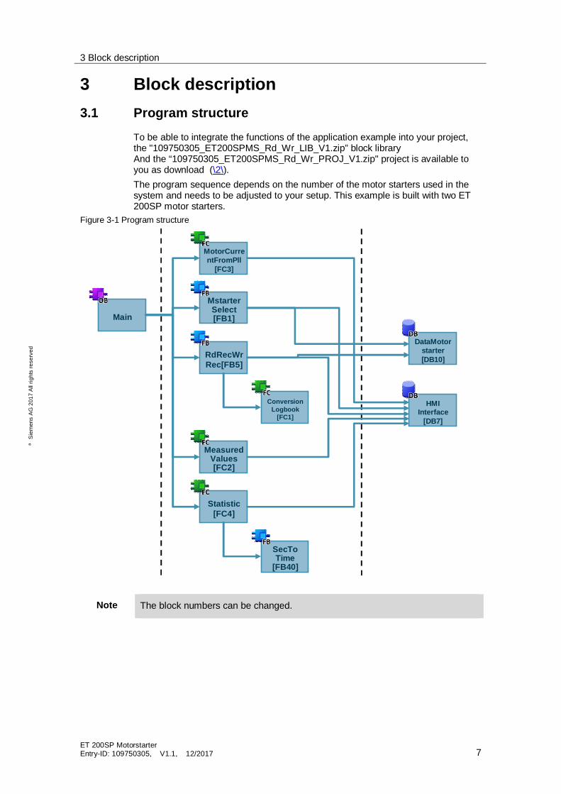
To be able to integrate the functions of the application example into your project,the "109750305_ET200SPMS_Rd_Wr_LIB_V1.zip” block libraryAnd the “109750305_ET200SPMS_Rd_Wr_PROJ_V1.zip" project is available toyou as download (\2\).The program sequence depends on the number of the motor starters used in thesystem and needs to be adjusted to your setup. This example is built with two ET200SP motor starters.
Figure 3-1 Program structure
Main
MotorCurrentFromPll
[FC3]
MstarterSelect[FB1]
RdRecWrRec[FB5]
ConversionLogbook
[FC1]
Statistic[FC4]
MeasuredValues[FC2]
SecToTime
[FB40]
HMIInterface
[DB7]
DataMotorstarter[DB10]
Note The block numbers can be changed.
3 Block description
ET 200SP MotorstarterEntry-ID: 109750305, V1.1, 12/2017 8
ãS
iem
ens
AG
2017
All
right
sre
serv
ed
The “109750305_ET200SPMS_Rd_Wr_LIB_V1.zip” block library offers thefollowing contents:· HMI_1: this is the complete HMI project· PLC data types: in this folder all data types created for the project have been
integrated· PLC program blocks: this folder contains all the program blocks, FBs, FCs and
DBs necessary for the creation of this application example· PLC tags: Contains the created tag chart for the example
To facilitate the use of the data sets, this application example uses the data typesfor the ET 200SP motor starter. These data types can be found in the IndustryOnline Support (see /6/).The “typeDataMotorStarter” data type has been newly created for the example. Inthis data type, all available data types for the ET 200SP motor starter have beenintegrated. It serves to assign the data of the ET 200SP motor starter, that arestored in “DataMotorstarter[DB10]”.The “typeFpLogbook” data type has also been newly created for the example andconsists of 21 entries which represent the scope of the logbooks and are nested inthe “typeDataMotorStarter” data type. The entries of the “typeFpLogbook” data typeagain subdivide into a “typeFpLogbookEntry” data type. It contains the informationof object number, day, hours, minutes and seconds which are calculated in the“ConversionLogbook [FC1]” and stored on the “DataMotorstarter [DB10]” datablock.In the following chapters, the program blocks are explained.

3 Block description
ET 200SP MotorstarterEntry-ID: 109750305, V1.1, 12/2017 9
ãS
iem
ens
AG
2017
All
right
sre
serv
ed
3.1.1 “MstarterSelect [FB1]”
Via the “MstarterSelect [FB1]” function block, the information from the HMI, whichmotor starter is currently selected at the panel, is transmitted. Additionally, theprocess image of the inputs is read in in this block.The following figure shows the call of the “MstarterSelect” block.Figure 3-2 Interconnected “MstarterSelect” FB1
The activation of the process image of the outputs is done separately in the OB1,so that there will not be any double accesses of the outputs in the further course ofyour application, see chapter 3.1.7 “Controlling the process image of the “.The “MstarterSelect” function block has the following inputs and inputs/outputs:Table 3-1 Inputs and inputs/outputs of the “MstarterSelect” FB
Name Data type Description
selectedStarter Int Here, the panel reads in the information about whichmotor starter has been selected.
motorStarterInput1 "LPD_typeMotorStarterIn"
Input address of the respective ET 200SP motorstarter. In this example, the process image of theinputs for the motor starter has been stored in theglobal tag chart on the “motorStarter1/2In” tags withthe “LPD_typeMotorStarterIn” data type. The statusof the inputs is stored on the “dataMotorstarter”output tag in the block.
motorStarterInput2 "LPD_typeMotorStarterIn"
dataMotorstarter Array[0..1] of“typeDataMotorStarter”
Contains the information of the motor starters that arestored after the RDREC or WRREC request.

3 Block description
ET 200SP MotorstarterEntry-ID: 109750305, V1.1, 12/2017 10
ãS
iem
ens
AG
2017
All
right
sre
serv
ed
The “MstarterSelect” block has the following outputs:Table 3-2 Outputs of “MstarterSelect” FB
Name Datatype
Description
reqMstarter1 Bool Serve as trigger, so that upon selecting a motor starter atthe HMI, all data sets are read out once consecutivelyand the current information from the data sets aredisplayed on the HMI.
reqMstarter2 Bool
dataMotorstarterIndexK
Int Index for the HMI. This way, the data of the selectedmotor starter are accessed via a multiplex tag at the HMI.
Note If you use more than two ET 200SP motor starters in your system setup, youneed to extend the block with further inputs and outputs.
The following figure exemplary shows, how the program needs to be adjusted forthe use of 20 ET 200SP motor starters.
Figure 3-3 Exemplary program extension “MstarterSelect” [FB1]

3 Block description
ET 200SP MotorstarterEntry-ID: 109750305, V1.1, 12/2017 11
ãS
iem
ens
AG
2017
All
right
sre
serv
ed
3.1.2 “MotorCurrentFromPll[FC3]”
With the function “MotorCurrentFromPII[FC3]”, a real motor current is calculated bythe 6bit values in the process image of the motor starter’s inputs, which display thecurrent motor current in percentage. (PII stands for Process Image of Inputs)The Figure below shows the call of the “MotorCurrentFromPII” function.Figure 3-4 Interconnected “MotorCurrentFromPII” FC3
The function has the following inputs and inputs/outputs:Table 3-3 Inputs and inputs/outputs of the “MotorCurrentFromPII” FC
Name Data type Description
inProcessValStarter1 Byte Address of input byte that reflects the motorcurrent from the process image of the motorstarter’s inputs.inProcessValStarter2 Byte
selectedStarter Int Here, the information from the “HMIInterface” DBis read out, which motor starter is currently active.
dataMotorstarter Array[0..1] of"typeDataMotorStarter"
Contains the information of the motor starters thatare stored after the RDREC or WRREC request.
The function has the following outputs:Table 3-4 Outputs of "MotorCurrentFromPll” FC
Name Datatype
Description
relativCurrentOfSelectedStarter%
Real Current value of the selected motor starter in percent.
absCurrentOfSelectedStarter
Real Absolute current value of the selected motor starter.
Note If you use more than two ET 200SP motor starters in your system setup, youneed to extend the block with further inputs and outputs.
The following figure exemplary shows, how the program needs to be adjusted forthe use of 20 ET 200SP motor starters.
3 Block description
ET 200SP MotorstarterEntry-ID: 109750305, V1.1, 12/2017 12
ãS
iem
ens
AG
2017
All
right
sre
serv
ed
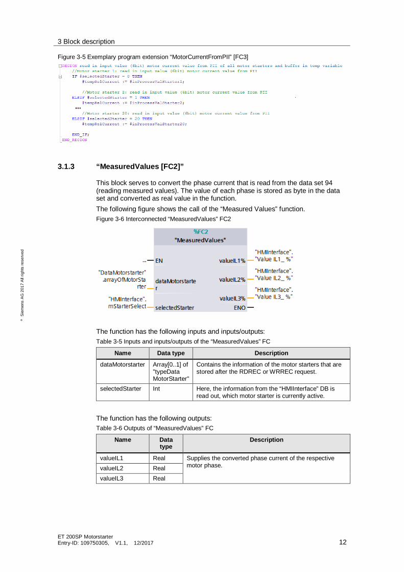
Figure 3-5 Exemplary program extension “MotorCurrentFromPII” [FC3]
3.1.3 “MeasuredValues [FC2]”
This block serves to convert the phase current that is read from the data set 94(reading measured values). The value of each phase is stored as byte in the dataset and converted as real value in the function.The following figure shows the call of the “Measured Values” function.Figure 3-6 Interconnected “MeasuredValues” FC2
The function has the following inputs and inputs/outputs:Table 3-5 Inputs and inputs/outputs of the “MeasuredValues” FC
Name Data type Description
dataMotorstarter Array[0..1] of"typeDataMotorStarter"
Contains the information of the motor starters that arestored after the RDREC or WRREC request.
selectedStarter Int Here, the information from the “HMIInterface” DB isread out, which motor starter is currently active.
The function has the following outputs:Table 3-6 Outputs of “MeasuredValues” FC
Name Datatype
Description
valueIL1 Real Supplies the converted phase current of the respectivemotor phase.valueIL2 Real
valueIL3 Real

3 Block description
ET 200SP MotorstarterEntry-ID: 109750305, V1.1, 12/2017 13
ãS
iem
ens
AG
2017
All
right
sre
serv
ed
3.1.4 “Statistic [FC4]” and “SecToTime [FB40]”
In the “Statistic [FC4]” block, the operating hours counter (which is read from thedata set 95 as second value) is converted into days, hours, minutes and seconds.The conversion is done via the “SecToTime [FB40]” function block that is called upin this block. The basic function of the “SecToTime [FB40]” block was taken fromthe “MillisecToTime” function(\8\).The converted values are transferred to the HMI via the “HMIInterface” DB.The following figure shows the interconnected “Statistic” block.Figure 3-7 Interconnected “Statistic” FC4
The block has the following inputs:Table 3-7 Inputs and inputs of “Statistic” FB
Name Data type Description
dataMotorstarter Array[0..1] of"typeDataMotorStarter"
Contains the information of the motor starters that arestored after the RDREC or WRREC request.
selectedStarter Int Here, the information from the “HMIInterface” DB isread out, which motor starter is currently active.
The block has the following outputs:Table 3-8 Outputs of “Statistic” FB
Name Datatype
Description
ohDay Int supplies the calculated day value from the operating hourscounter
ohHours Int supplies the calculated hour value from the operatinghours counter
ohMin Int supplies the calculated second value from the operatinghours counter
ohSec Int supplies the calculated minute value from the operatinghours counter
3 Block description
ET 200SP MotorstarterEntry-ID: 109750305, V1.1, 12/2017 14
ãS
iem
ens
AG
2017
All
right
sre
serv
ed
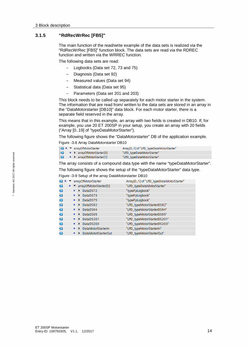
3.1.5 “RdRecWrRec [FB5]”
The main function of the read/write example of the data sets is realized via the“RdRecWrRec [FB5]” function block. The data sets are read via the RDRECfunction and written via the WRREC function.The following data sets are read:
– Logbooks (Data set 72, 73 and 75)– Diagnosis (Data set 92)– Measured values (Data set 94)– Statistical data (Data set 95)– Parameters (Data set 201 and 203)
This block needs to be called up separately for each motor starter in the system.The information that are read from/ written to the data sets are stored in an array inthe “DataMotorstarter [DB10]” data block. For each motor starter, there is aseparate field reserved in the array.This means that in this example, an array with two fields is created in DB10. If, forexample, you use 20 ET 200SP in your setup, you create an array with 20 fields(“Array [0..19] of "typeDataMotorStarter”).The following figure shows the “DataMotorstarter” DB of the application example.Figure -3-8 Array DataMotorstarter DB10
The array consists of a compound data type with the name “typeDataMotorStarter”.The following figure shows the setup of the “typeDataMotorStarter” data type.Figure -3-9 Setup of the array DataMotorstarter DB10
3 Block description
ET 200SP MotorstarterEntry-ID: 109750305, V1.1, 12/2017 15
ãS
iem
ens
AG
2017
All
right
sre
serv
ed
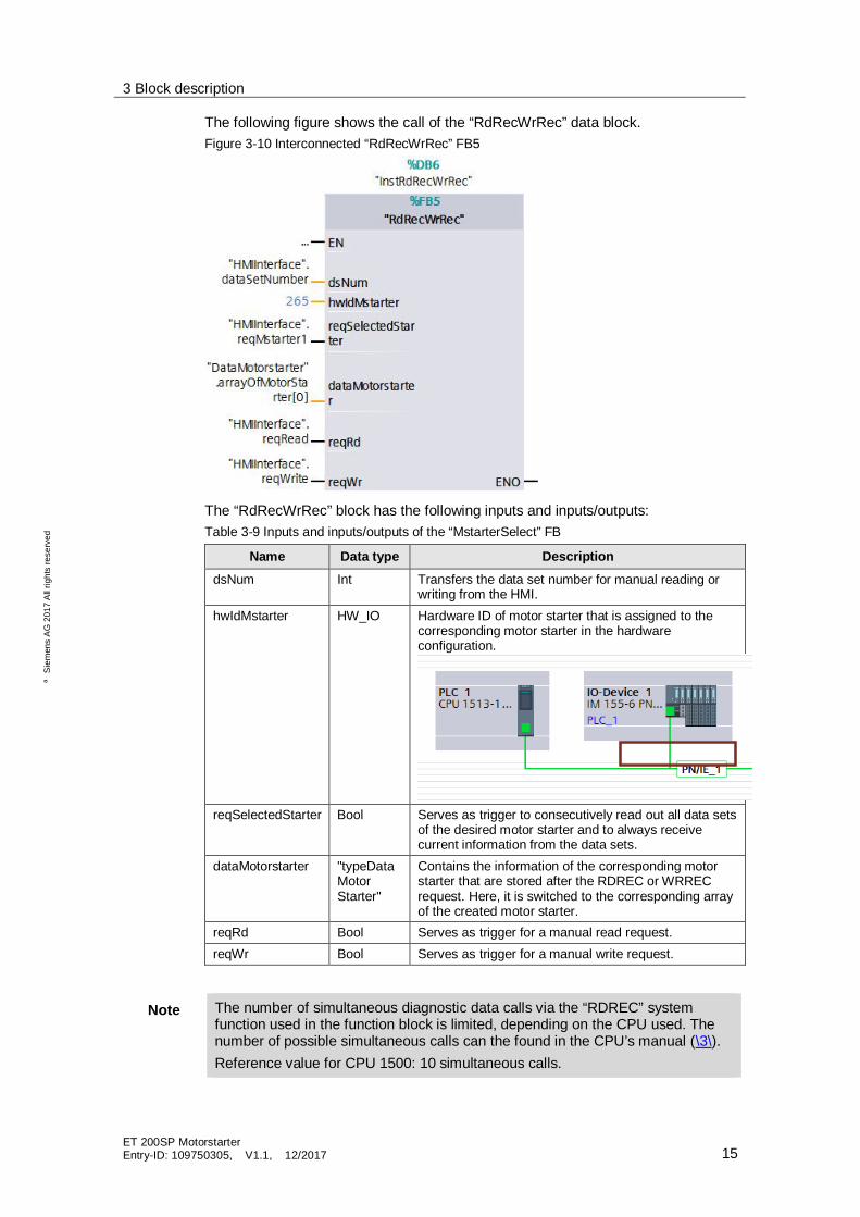
The following figure shows the call of the “RdRecWrRec” data block.Figure 3-10 Interconnected “RdRecWrRec” FB5
The “RdRecWrRec” block has the following inputs and inputs/outputs:Table 3-9 Inputs and inputs/outputs of the “MstarterSelect” FB
Name Data type DescriptiondsNum Int Transfers the data set number for manual reading or
writing from the HMI.hwIdMstarter HW_IO Hardware ID of motor starter that is assigned to the
corresponding motor starter in the hardwareconfiguration.
reqSelectedStarter Bool Serves as trigger to consecutively read out all data setsof the desired motor starter and to always receivecurrent information from the data sets.
dataMotorstarter "typeDataMotorStarter"
Contains the information of the corresponding motorstarter that are stored after the RDREC or WRRECrequest. Here, it is switched to the corresponding arrayof the created motor starter.
reqRd Bool Serves as trigger for a manual read request.reqWr Bool Serves as trigger for a manual write request.
Note The number of simultaneous diagnostic data calls via the “RDREC” systemfunction used in the function block is limited, depending on the CPU used. Thenumber of possible simultaneous calls can the found in the CPU’s manual (\3\).Reference value for CPU 1500: 10 simultaneous calls.

3 Block description
ET 200SP MotorstarterEntry-ID: 109750305, V1.1, 12/2017 16
ãS
iem
ens
AG
2017
All
right
sre
serv
ed
3.1.6 “ConversionLogbook [FC1]”
During the read-out of the motor starter’s logbooks, the operating hours of thedevice and an object number for each event are read. The operating hours counteris specified as second value. To make a precise statement as to when an eventtook place, this second value is converted into days, hours, minutes and secondsin the “ConversionLogbook[FC1]” function. After the read-out of the logbooksDS72, DS73 and DS75, the block is called up in the “RdRecWrRec [FB5]” functionblock.
3.1.7 Controlling the process image of the outputs
In order to make sure that there are no simultaneous accesses to the processimage of the ET 200SP motor starters’ outputs from multiple points, the outputs areindividually described in OB1. This way, you can integrate your additional switchingconditions at this interface for your application.In this example, the process image of the outputs for the motor starter has beenstored in the global tag chart on the “motorStarter1/2Out” tags with the“LPD_typeMotorStarterOut” data type.To be able to switch the outputs via the HMI image “motor control”, the outputs ofthe used motor starter need to be switched in OB1. If you use more than two ET200SP motor starters in your system setup, you need to extend the switchingaccordingly.The following figure shows the interconnection of the process image of the outputs,using the example of “motorStarter1Out”.Figure 3-11 Exemplary switching of the process image of the outputs

4 Operating the application example
ET 200SP MotorstarterEntry-ID: 109750305, V1.1, 12/2017 17
ãS
iem
ens
AG
2017
All
right
sre
serv
ed
4 Operating the application example4.1 Overview
The following figure shows the start screen of the HMI.Figure 4-1 Start screen on HMI
The HMI project consists of 6 screens. These screens display the read informationfrom the data sets of the used ET 200SP motor starter. Besides the systemdiagnostics window, a start, a system and a support screen are also integrated.In the following, it will be described in detail how to operate the individual screens.

4 Operating the application example
ET 200SP MotorstarterEntry-ID: 109750305, V1.1, 12/2017 18
ãS
iem
ens
AG
2017
All
right
sre
serv
ed
4.2 Operation
4.2.1 Toolbar
The individual screens are selected via the toolbar on the right. It is possible toaccess the following screens from anywhere:
· Start screen· Motor control· Change parameters· Device logbooks· Device diagnosis· Measured values· Statistics· System· Support
4.2.2 System diagnostics window
A diagnostics button to call up the system diagnostics window is integrated in thetoolbar.Figure 4-2 Button to call up the system diagnostics
The System diagnostics window offers you an overview of all available devices inyour plant. You navigate directly to the cause of the error and to the respectivedevice. You have access to all diagnostics-capable devices which you haveconfigured in the "Devices & Networks" editor.Figure 4-3 Extract from the “System diagnostics window”

4 Operating the application example
ET 200SP MotorstarterEntry-ID: 109750305, V1.1, 12/2017 19
ãS
iem
ens
AG
2017
All
right
sre
serv
ed
4.2.3 Using faceplates
In this application example, the contents of the HMI screens are generated asfaceplates. A faceplate is a block that makes it easier for you to connect theindividual process tags to the HMI. You also get the advantage of being able to usethe faceplate for several panels and to adjust it for each panel size.Further information on faceplates can be found in the Industry Online Support(\9\).To connect the process tags to the faceplate, click on the faceplate and go to“Interface”. Now, all process tags to be connected are displayed.Figure 4-4 Interface for the faceplate
4.2.4 Selecting the motor starter
To receive the correct values of the desired motor starter, you need to select amotor starter after selecting an HMI screen. To do this, there is a dropdown menuin the upper right corner.Figure 4-5 Selecting motor starter 1
To expand the display and integrate further motor starters into this selection field,and to adjust the names for your application, the dropdown menu can be adjustedat “Screen templates > Template_Topic > Properties.Figure 4-6 Editing the dropdown menu

4 Operating the application example
ET 200SP MotorstarterEntry-ID: 109750305, V1.1, 12/2017 20
ãS
iem
ens
AG
2017
All
right
sre
serv
ed
If you now open the text list “motorselection”, you can add further motor starters tothe selection by adding new entries to the text list (“Add new”).Figure 4-7 Expanding the “motorselection” text list
The value for “Starter1” = 0 and “Starter2” = 1 is stored in the “HMIInterface” DB inthe “mStarterSelect” tags and interconnected at several program blocks.

4 Operating the application example
ET 200SP MotorstarterEntry-ID: 109750305, V1.1, 12/2017 21
ãS
iem
ens
AG
2017
All
right
sre
serv
ed
4.2.5 Motor control
The following figure shows the HMI screen “Motor control”.Figure 4-8 HMI screen “Motor control”
In the HMI screen “motor control”, the process image of the motor starter’s inputsas well as the process image of the outputs is shown. This provides you with thestatus of the selected motor starter and allows you to activate it manually, or resetan error. Additionally, the current motor current is displayed in % and as real valuein [A] in the upper screen area.
Note The process image of the inputs and outputs are connected to the panel asmultiplex tags (DataMotorstarter_k.DataMotorStarterIn,DataMotorstarter_k.DataMotorStarterOut). Please note that the “Symbolicmultiplexing” is available only for TIA Portal version V 14 and higher.

4 Operating the application example
ET 200SP MotorstarterEntry-ID: 109750305, V1.1, 12/2017 22
ãS
iem
ens
AG
2017
All
right
sre
serv
ed
4.2.6 Change parameters
The following figure shows the HMI screen “Change parameters”.Figure 4-9 HMI screen “Change parameters”
In the HMI screen “Change parameters”, you have the option of adjusting the ratedoperational current Ie. The entered value of the rated operational current needs tobe in the value range of the selected motor starter, otherwise, the parameter willnot be accepted. This means that, for an ET 200SP motor starter DS 0.9-3A (3RK1308-0AC00-0CP0), only values between 0.9 - 3 can be entered. Parameterscannot be written during motor operation. For a parameter change, the motorneeds to be stopped and the local manual operation needs to be deactivated.Additionally, the parameters “Response to residual current detection” and“Response to asymmetry” can be changed between “Warn” and “Tripping”.Figure 4-10 Changing the parameters “Residual current detection” and “Asymmetry”
Note Please note that after a CPU restart or after module missing, the writtendevice parameter are written over again by the original parameterizationfrom the hardware configuration.

4 Operating the application example
ET 200SP MotorstarterEntry-ID: 109750305, V1.1, 12/2017 23
ãS
iem
ens
AG
2017
All
right
sre
serv
ed
You will see this note if you want to write the parameter.
Abbildung 4-11

4 Operating the application example
ET 200SP MotorstarterEntry-ID: 109750305, V1.1, 12/2017 24
ãS
iem
ens
AG
2017
All
right
sre
serv
ed
4.2.7 Device logbooks
The following figure shows the HMI screen “Device logbooks”.Figure 4-12 HMI screen “Device logbooks - Logbook ‘events’”
There are 3 different logbooks for the ET 200SP motor starter:· DS72 logbook device errors· DS73 logbook triggering operations· DS75 logbook events
In the HMI screen “Device logbooks”, all 3 variants can be found. The logbooks canbe navigated through via the arrow keys in the lower right corner. For each enteredevent, the time is additionally displayed in days, hours, minutes and seconds. Thisis the operating hours counter in the device, which means that the exact time ofwhen an event occurred in the device will be recorded.In the logbooks “Events” and “Triggering operations”, most entries will usually befound, which is why the view starts with the logbook “Events”, followed by thelogbook “Triggering operations” and finally the logbook “Device errors”. It may wellbe that there are no entries in the logbook “Device errors”. Here, errors that occurin the hardware are entered.
Note The logbook entries are connected to the panel as multiplex tags. Please notethat the “Symbolic multiplexing” is available only for TIA Portal version V 14 andhigher.

4 Operating the application example
ET 200SP MotorstarterEntry-ID: 109750305, V1.1, 12/2017 25
ãS
iem
ens
AG
2017
All
right
sre
serv
ed
The following figure shows the HMI screen “Device logbooks”.Figure 4-13 HMI screen “Triggering operations”
The following figure shows the HMI screen “Device logbook during a device error”.Figure 4-14 HMI screen logbook “Device errors”
4 Operating the application example
ET 200SP MotorstarterEntry-ID: 109750305, V1.1, 12/2017 26
ãS
iem
ens
AG
2017
All
right
sre
serv
ed
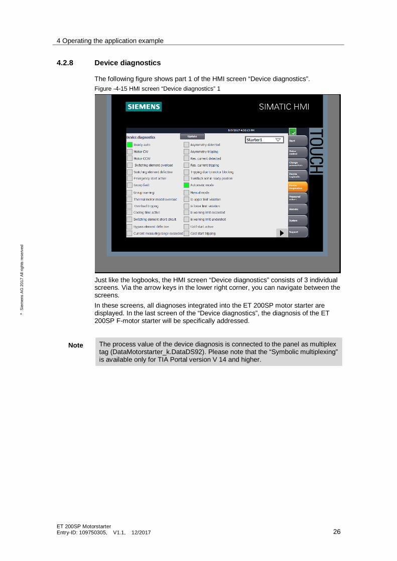
4.2.8 Device diagnostics
The following figure shows part 1 of the HMI screen “Device diagnostics”.Figure -4-15 HMI screen “Device diagnostics” 1
Just like the logbooks, the HMI screen “Device diagnostics” consists of 3 individualscreens. Via the arrow keys in the lower right corner, you can navigate between thescreens.In these screens, all diagnoses integrated into the ET 200SP motor starter aredisplayed. In the last screen of the “Device diagnostics”, the diagnosis of the ET200SP F-motor starter will be specifically addressed.
Note The process value of the device diagnosis is connected to the panel as multiplextag (DataMotorstarter_k.DataDS92). Please note that the “Symbolic multiplexing”is available only for TIA Portal version V 14 and higher.

4 Operating the application example
ET 200SP MotorstarterEntry-ID: 109750305, V1.1, 12/2017 27
ãS
iem
ens
AG
2017
All
right
sre
serv
ed
The following figure shows part 2 of the HMI screen “Device diagnostics”.Figure -4-16 HMI screen “Device diagnostics” 2
From the DS92, a faulty parameter number can also be read. Here, numericalvalues that reflect object numbers are entered. The interpretation can be done withthe device manual of the ET 200SP motor starter (\5\).Figure 4-17 Output of a faulty parameter number

4 Operating the application example
ET 200SP MotorstarterEntry-ID: 109750305, V1.1, 12/2017 28
ãS
iem
ens
AG
2017
All
right
sre
serv
ed
The following figure shows the HMI screen “Device diagnostics” of the F-motorstarter.Figure -4-18 HMI screen “Device diagnostics F-motor starter”
4.2.9 Measured values
The following figure shows the HMI screen “Measured values”.Figure 4-19 HMI screen “Read measured values”

4 Operating the application example
ET 200SP MotorstarterEntry-ID: 109750305, V1.1, 12/2017 29
ãS
iem
ens
AG
2017
All
right
sre
serv
ed
In the HMI screen “Measured values”, the information from the data set 94 aredisplayed. The different phase currents can be viewed in % as well as in [A] so thatyou can assess the occupancy rate of the individual subordinate actuators.The displayed data are not displayed cyclically, however, they can be updated viathe “Update” button.
Note If you integrate a cyclic evaluation of the data into your project, please note thatthis affects the cycle time of the OB1.
4.2.10 Statistics
The following figure shows the HMI screen “Statistics”.Figure 4-20 HMI screen “Read statistics”
In the HMI screen “Statistics”, the information from data set 95 are displayed. It isevaluated, how often the motor starter has been activated (in clockwise or anti-clockwise rotation), how high the maximum motor current in [A] is, and differenttripping conditions are also counted. The operating hours counter of the device isspecified in days, hours, minutes and seconds.The displayed data are not displayed cyclically, however, they can be updated viathe “Update” button.
Note If you integrate a cyclic evaluation of the data into your project, please note thatthis affects the cycle time of the OB1.

4 Operating the application example
ET 200SP MotorstarterEntry-ID: 109750305, V1.1, 12/2017 30
ãS
iem
ens
AG
2017
All
right
sre
serv
ed
4.2.11 System & support
The following figure shows the HMI screens “System” and “Support”.Figure 4-21 HMI screens "System" and "Support"
The HMI screens "System" and "Support” are integrated into the project asassistance. No functions of the ET 200SP motor starter are displayed in thesescreens.Under “Support” and “System”, you also have the option of switching between theGerman and English language.

5 Other setup options
ET 200SP MotorstarterEntry-ID: 109750305, V1.1, 12/2017 31
ãS
iem
ens
AG
2017
All
right
sre
serv
ed
5 Other setup optionsThe setup shown in this application example is not mandatory. Your system mayvary from this setup and can be structured individually. Two possible variants aredescribed below:The following figure shows a variant with an S7-1500 F-CPU as well as standardand failsafe motor startersFigure 5-1 Example: Standard and Failsafe ET 200SP motor starters with S7-1500 F-CPU
ET 200SP SystemCPU 1516F-3PN/DP
PROFINET IE
Comfort Panel TP700
The following figure shows a variant with an ET 200SP CPU as well as standardand failsafe motor startersFigure 5-2 Example: Standard and failsafe ET 200SP motor starters centrally on ET 200SP
CPU
ET 200 SP CPU System
PROFINET IE
Comfort Panel TP700

6 Appendix
ET 200SP MotorstarterEntry-ID: 109750305, V1.1, 12/2017 32
ãS
iem
ens
AG
2017
All
right
sre
serv
ed
6 Appendix6.1 Service & support
Industry Online SupportDo you have any questions or need support?Siemens Industry Online Support offers access to our entire service and supportknow-how as well as to our services.Siemens Industry Online Support is the central address for information on ourproducts, solutions and services.Product information, manuals, downloads, FAQs and application examples – allinformation is accessible with just a few mouse clicks athttps://support.industry.siemens.com
Technical SupportSiemens Industry's Technical Support offers quick and competent supportregarding all technical queries with numerous tailor-made offers – from basic support right up to individual support contracts.Please address your requests to the Technical Support via the web form:www.siemens.com/industry/supportrequests
Service offerOur service offer comprises, among other things, the following services:· Product Training· Plant Data Services· Spare Parts Services· Repair Services· On Site and Maintenance Services· Retrofit and Modernization Services· Service Programs and AgreementsDetailed information on our service offer is available in the Service Catalog:https://support.industry.siemens.com/cs/sc
Industry Online Support appThanks to the "Siemens Industry Online Support" app, you will get optimumsupport even when you are on the move. The app is available for Apple iOS,Android and Windows Phone.https://support.industry.siemens.com/cs/ww/en/sc/2067
6 Appendix
ET 200SP MotorstarterEntry-ID: 109750305, V1.1, 12/2017 33
ãS
iem
ens
AG
2017
All
right
sre
serv
ed
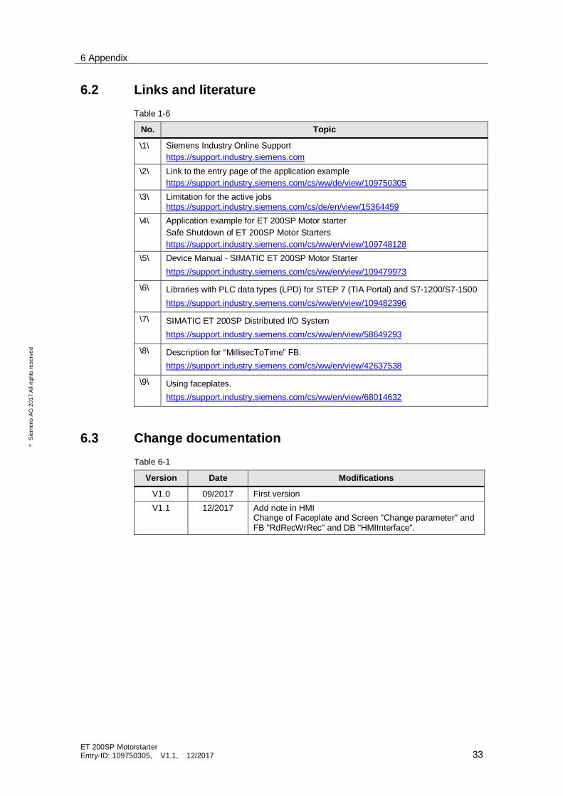
6.2 Links and literatureTable 1-6
No. Topic
\1\ Siemens Industry Online Supporthttps://support.industry.siemens.com
\2\ Link to the entry page of the application examplehttps://support.industry.siemens.com/cs/ww/de/view/109750305
\3\ Limitation for the active jobshttps://support.industry.siemens.com/cs/de/en/view/15364459
\4\ Application example for ET 200SP Motor starterSafe Shutdown of ET 200SP Motor Startershttps://support.industry.siemens.com/cs/ww/en/view/109748128
\5\ Device Manual - SIMATIC ET 200SP Motor Starterhttps://support.industry.siemens.com/cs/ww/en/view/109479973
\6\ Libraries with PLC data types (LPD) for STEP 7 (TIA Portal) and S7-1200/S7-1500https://support.industry.siemens.com/cs/ww/en/view/109482396
\7\ SIMATIC ET 200SP Distributed I/O Systemhttps://support.industry.siemens.com/cs/ww/en/view/58649293
\8\ Description for “MillisecToTime” FB.https://support.industry.siemens.com/cs/ww/en/view/42637538
\9\ Using faceplates.https://support.industry.siemens.com/cs/ww/en/view/68014632
6.3 Change documentationTable 6-1
Version Date Modifications
V1.0 09/2017 First versionV1.1 12/2017 Add note in HMI
Change of Faceplate and Screen "Change parameter" andFB "RdRecWrRec" and DB "HMIInterface".


![PILOT TONE DETECTION MODULE VX-200SP-2 ...3 1. GENErAL DESCrIPTION [VX-200SP-2] The VX-200SP-2 is an audio signal output module of the VX-2000 system with speaker line pilot tone detection](https://img.pdfslide.net/doc/110x75/5fe8671170ebfb54a6199e1c/pilot-tone-detection-module-vx-200sp-2-3-1-general-description-vx-200sp-2.jpg)