Embed Size (px)
Citation preview
User Manual For ET-BASE AVR (ATmega8535)
-1- WWW.ETT.CO.THETT CO., LTD.
ET-BASE AVR (ATmega8535)
ET-BASE AVR which is AVR Board Microcontroller from ATMEL has MCU No. Atmega8535 40 Pin in circuit. Board ET-BASE AVR uses MCU resources as main and I/O PORT are arranged as PORT PA, PB, PC, PD with PORT to download program, it is easy to use. Moreover, there’s additional Driver RS-232 circuit in board for using with RS232 Serial Port easily.
SPECIFICATIONS
• Support AVR Microcontroller 40 PIN No. AT90S8535, ATmega8535, ATmega16, ATmega163 • Run Crystal 8 MHz • 4-CH.I/O PORT 10 PIN : PORT-PA, PORT-PB, PORT-PC, PORT-PD • Port ET-PSPI Download for Program MCU • 1-CH. RS232 Serial Port • LED Display: Red Color for Power, Green color for Download and Yellow color for Self Test • Power Supply +5V DC and GND
STRUCTURE OF BOARD
3 5
10
71
1415
11
2
12
8
6
169
4
13
User Manual For ET-BASE AVR (ATmega8535)
-2- WWW.ETT.CO.THETT CO., LTD.
• No.1 is Port for connecting with Power supply +5V DC
1 2
GND
+5V
• No.2 is Jumper be able to select for connecting between LED of No. 16 or PORT PB0 as in the
picture LED/PB0
• No.3 is Reset Switch • No.4 is AVR Microcontroller 40 Pin No. AT90S8535/mega8535/mega16/mega163 • No.5 is Jumper be able to select for connecting between RS232 or I/O Port (PD0, PD1) as in the
picture PD1
PD0
I/O
RS232
• No.6 and No.7 are Connecting Point of Power Supply +5V and GND chronologically • No.8, 9, 10, and 11 are 4-CH.I/O Port: PORT-PC, PORT-PA, PORT-PB and PORT-PD
chronologically
PC2PC4PC6
+VCC
PC3PC5PC7GND
PC1PC0
PORT-PC[0..7]
PA2PA4PA6
+VCC
PA3PA5PA7GND
PA1PA0
PORT-PA[0..7]
PB2PB4PB6
+VCC
PB3PB5PB7GND
PB1PB0
PORT-PB[0..7]
PD2PD4PD6
+VCC
PD3PD5PD7GND
PD1PD0
PORT-PD[0..7]
• No.12 is PORT ET-PSPI DOWNLOAD for connecting ET-CAB10PIN to program HEX FILE into AVR and are arranged as in the picture
NCNC
MISOMOSI
NCSSRESSCK
GND+VCC
ET-PSPI DOWNLOAD
User Manual For ET-BASE AVR (ATmega8535)
-3- WWW.ETT.CO.THETT CO., LTD.
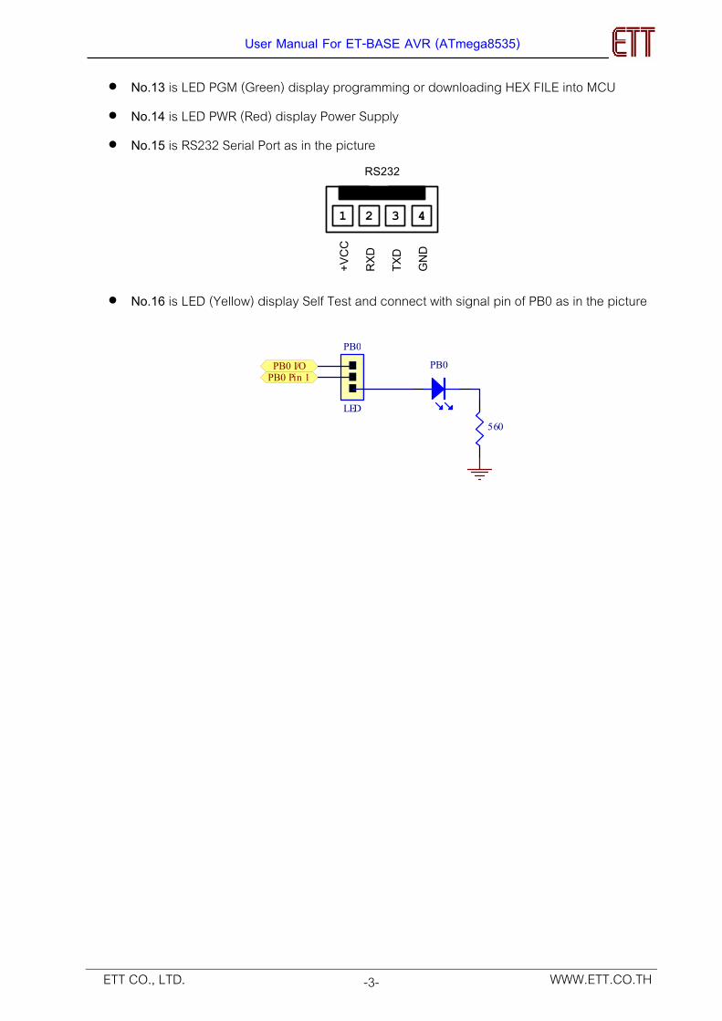
• No.13 is LED PGM (Green) display programming or downloading HEX FILE into MCU • No.14 is LED PWR (Red) display Power Supply • No.15 is RS232 Serial Port as in the picture
2 41 3
+VCC
RXD
TXD
GND
RS232
• No.16 is LED (Yellow) display Self Test and connect with signal pin of PB0 as in the picture
560
PB0PB0 Pin 1PB0 I/O
LED
PB0
User Manual For ET-BASE AVR (ATmega8535)
-4- WWW.ETT.CO.THETT CO., LTD.
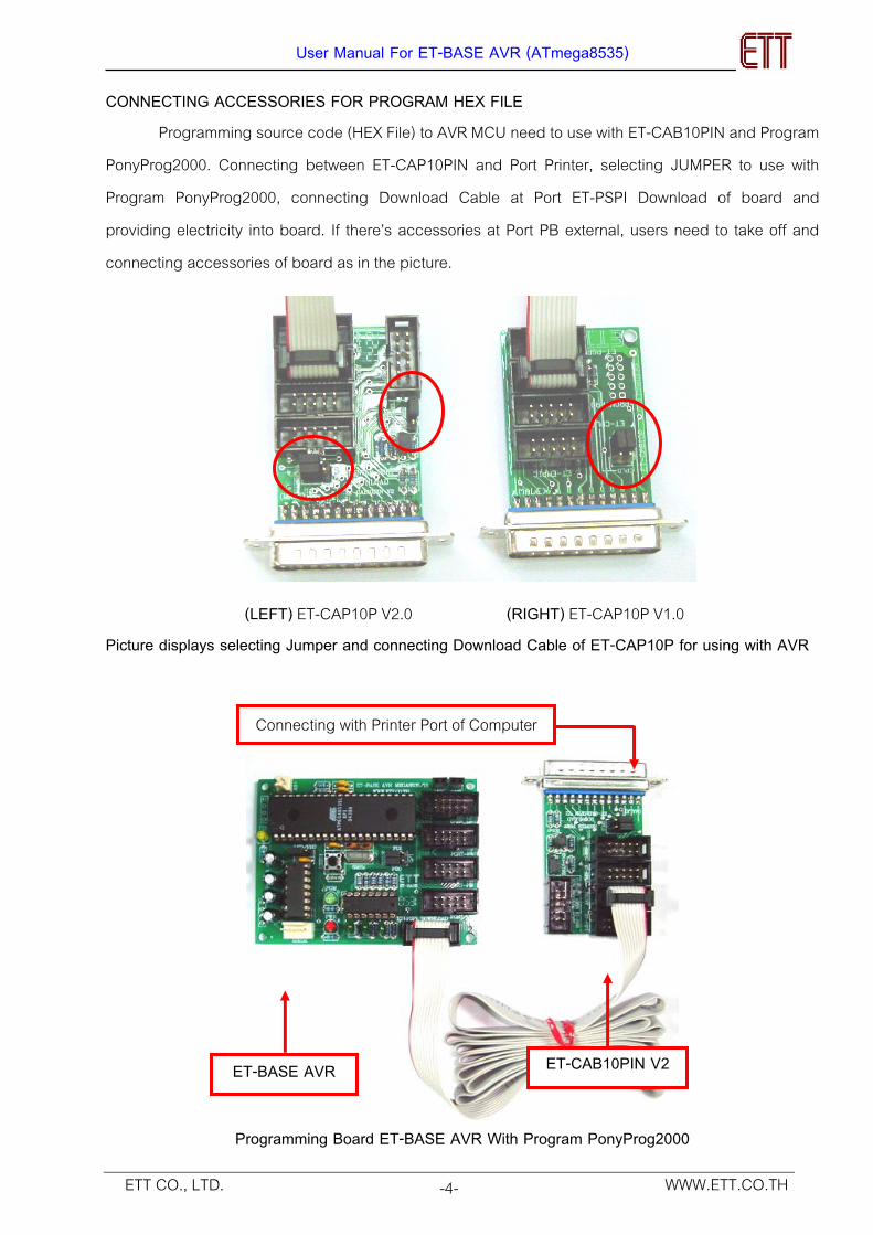
CONNECTING ACCESSORIES FOR PROGRAM HEX FILE Programming source code (HEX File) to AVR MCU need to use with ET-CAB10PIN and Program PonyProg2000. Connecting between ET-CAP10PIN and Port Printer, selecting JUMPER to use with Program PonyProg2000, connecting Download Cable at Port ET-PSPI Download of board and providing electricity into board. If there’s accessories at Port PB external, users need to take off and connecting accessories of board as in the picture.
(LEFT) ET-CAP10P V2.0 (RIGHT) ET-CAP10P V1.0 Picture displays selecting Jumper and connecting Download Cable of ET-CAP10P for using with AVR
Programming Board ET-BASE AVR With Program PonyProg2000
ET-CAB10PIN V2 ET-BASE AVR
Connecting with Printer Port of Computer
User Manual For ET-BASE AVR (ATmega8535)
-5- WWW.ETT.CO.THETT CO., LTD.
DOWNLOAD HEX File to MCU
PROGRAM PonyProg2000 which is Program Download HEX FILE into CPU AVR as Serial
programming is able to use with ETT AVR Board well. Users can learn them from HELP of program and in this case we would like to introduction the proceeding of SETUP PROGRAM PonyProg2000 for using with ETT AVR Board. It is able to use with all ETT AVR Board.
In case of using CPU AVR No. ATmega8535 and ATmega16, there’s one notice to be careful. Because structure inside of ATmega8535 has various Fuse Bit for set condition of running CPU and some Fuse Bit is effect on Download Serial Programming. If users set Fuse Bit incorrectly, it won’t program into CPU with Download Serial programming, users need to correct Fuse Bit with Program Parallel Programming CPU AVR for using ETT Board with Program PonyProg2000, users need to set option as following;
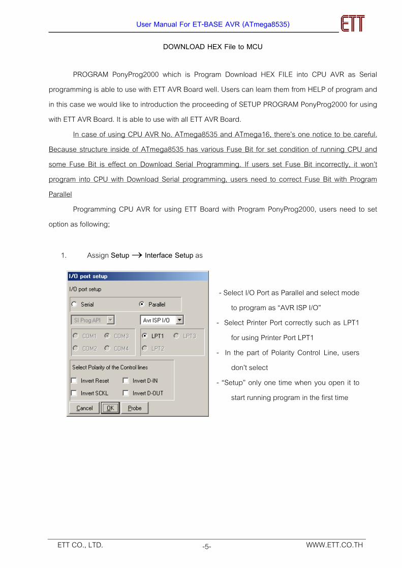
1. Assign Setup → Interface Setup as
- Select I/O Port as Parallel and select mode
to program as “AVR ISP I/O” - Select Printer Port correctly such as LPT1
for using Printer Port LPT1 - In the part of Polarity Control Line, users
don’t select - “Setup” only one time when you open it to
start running program in the first time
User Manual For ET-BASE AVR (ATmega8535)
-6- WWW.ETT.CO.THETT CO., LTD.
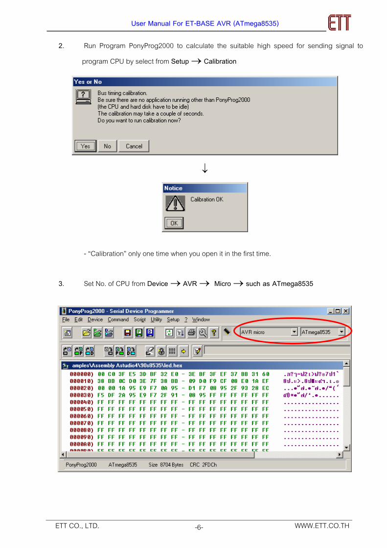
2. Run Program PonyProg2000 to calculate the suitable high speed for sending signal to
program CPU by select from Setup → Calibration
↓
- “Calibration” only one time when you open it in the first time.
3. Set No. of CPU from Device → AVR → Micro → such as ATmega8535
User Manual For ET-BASE AVR (ATmega8535)
-7- WWW.ETT.CO.THETT CO., LTD.
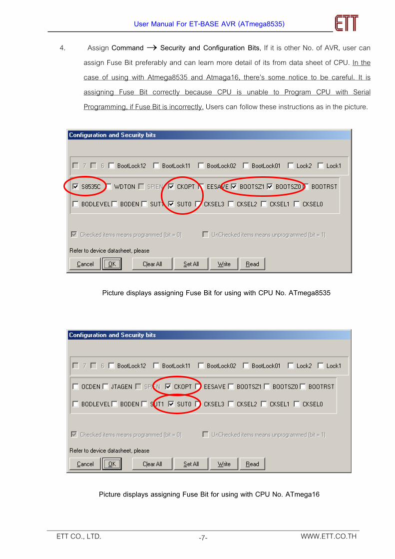
4. Assign Command → Security and Configuration Bits, If it is other No. of AVR, user can
assign Fuse Bit preferably and can learn more detail of its from data sheet of CPU. In the case of using with Atmega8535 and Atmaga16, there’s some notice to be careful. It is assigning Fuse Bit correctly because CPU is unable to Program CPU with Serial Programming, if Fuse Bit is incorrectly. Users can follow these instructions as in the picture.
Picture displays assigning Fuse Bit for using with CPU No. ATmega8535
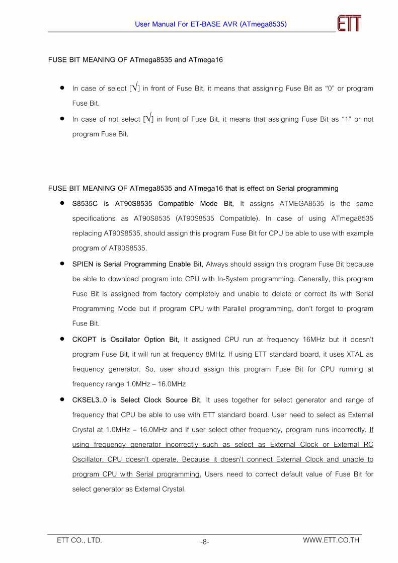
Picture displays assigning Fuse Bit for using with CPU No. ATmega16
User Manual For ET-BASE AVR (ATmega8535)
-8- WWW.ETT.CO.THETT CO., LTD.
FUSE BIT MEANING OF ATmega8535 and ATmega16
• In case of select [√] in front of Fuse Bit, it means that assigning Fuse Bit as “0” or program Fuse Bit.
• In case of not select [√] in front of Fuse Bit, it means that assigning Fuse Bit as “1” or not program Fuse Bit.
FUSE BIT MEANING OF ATmega8535 and ATmega16 that is effect on Serial programming
• S8535C is AT90S8535 Compatible Mode Bit, It assigns ATMEGA8535 is the same specifications as AT90S8535 (AT90S8535 Compatible). In case of using ATmega8535 replacing AT90S8535, should assign this program Fuse Bit for CPU be able to use with example program of AT90S8535.
• SPIEN is Serial Programming Enable Bit, Always should assign this program Fuse Bit because be able to download program into CPU with In-System programming. Generally, this program Fuse Bit is assigned from factory completely and unable to delete or correct its with Serial Programming Mode but if program CPU with Parallel programming, don’t forget to program Fuse Bit.
• CKOPT is Oscillator Option Bit, It assigned CPU run at frequency 16MHz but it doesn’t program Fuse Bit, it will run at frequency 8MHz. If using ETT standard board, it uses XTAL as frequency generator. So, user should assign this program Fuse Bit for CPU running at frequency range 1.0MHz – 16.0MHz
• CKSEL3..0 is Select Clock Source Bit, It uses together for select generator and range of frequency that CPU be able to use with ETT standard board. User need to select as External Crystal at 1.0MHz – 16.0MHz and if user select other frequency, program runs incorrectly. If using frequency generator incorrectly such as select as External Clock or External RC Oscillator, CPU doesn’t operate. Because it doesn’t connect External Clock and unable to program CPU with Serial programming. Users need to correct default value of Fuse Bit for select generator as External Crystal.
User Manual For ET-BASE AVR (ATmega8535)
-9- WWW.ETT.CO.THETT CO., LTD.
Frequency Generator of AVR Atmega8535 and ATmega16
Setting Fuse Bit ของ CKSEL[3…0] (0=Program,1=Un-Program)
Ex te rna l Crys ta l /Ceramic Resona to r 1111-1010 External Low Frequency Crystal 1001 External RC Oscillator 1000-0101 Calibrated Internal RC Oscillator 0100-0001 External Clock 0000
Table displays Frequency of Fuse Bit CKSEL [3..0]
REMARKS - Value “1”. It means that not program Fuse Bit and doesn’t tick [√] any mark in front of
Fuse Bit. - Value “0”. It means that program Fuse Bit and ticks mark [√]in front of Fuse Bit. - In case of using with Atmega8535, user need to program Fuse Bit of S8535C for
ATmega8535 is the same specifications as AT90S8535. - Should program Fuse Bit of CKOPT at Frequency 1.0MHz – 16.00MHz - Not allowed to program Fuse Bit of CKSEL [3..0] because its operation is incorrect. For
example, if all program Fuse Bit of CKSEL [3..0] is “0”, after written value to Fuse Bit by Program PonyProg2000 completely. CPU is unable to use with ETT board and unable to program Fuse Bite with Serial programming. Because circuit of External Crystal stop to run and be able to use with External Clock only but ETT board uses with circuit External Crystal only. So, users need to correct CPU with Parallel program and it will use program Fuse Bit with Serial Programming.
- Position Fuse Bit of Lock [2..1] be able to assign preferably
User Manual For ET-BASE AVR (ATmega8535)
-10- WWW.ETT.CO.THETT CO., LTD.
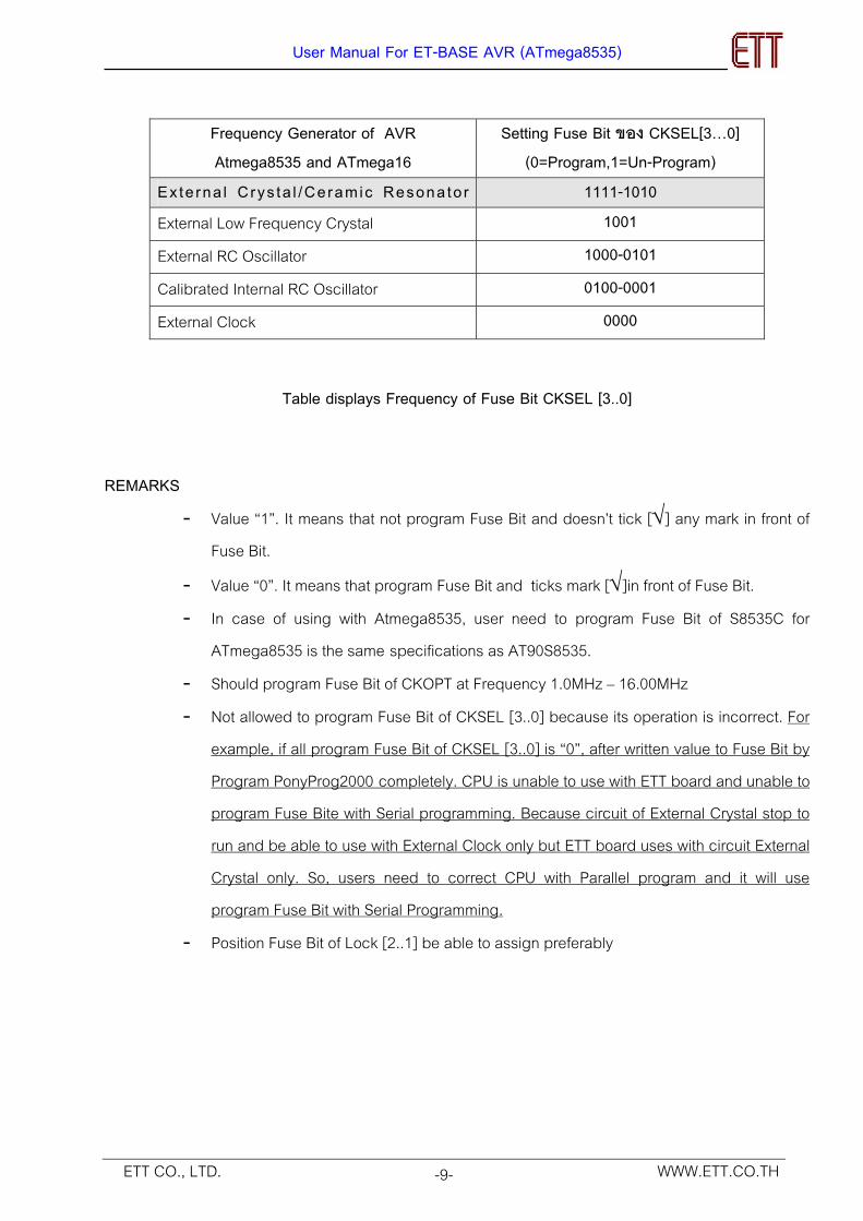
5. Select Command → Program Option as;
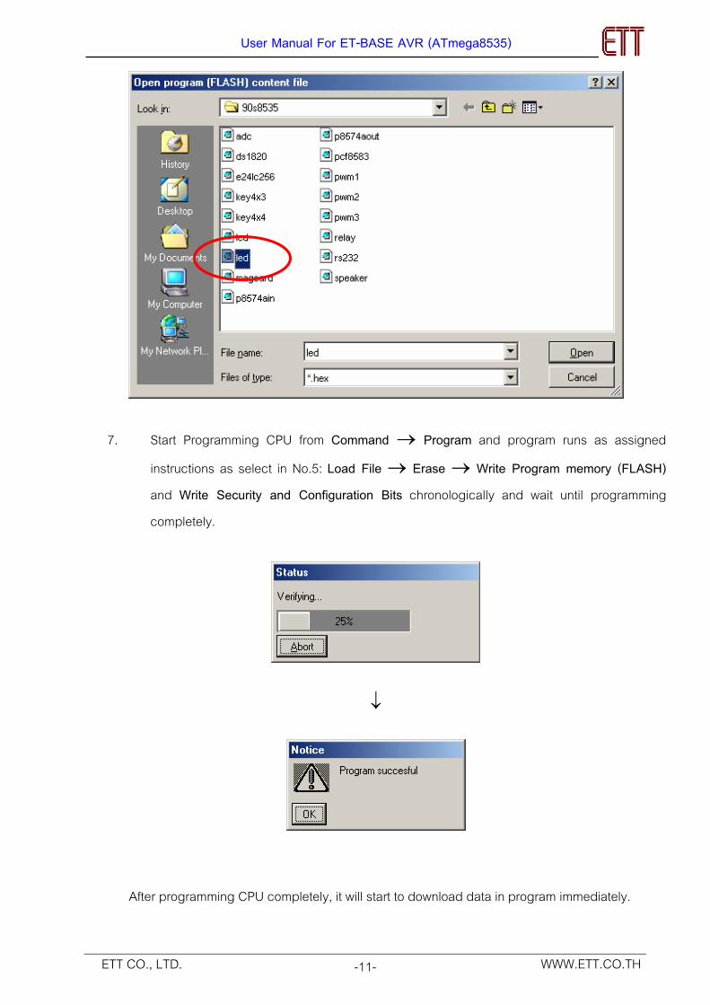
6. Open file for Programming CPU from File → Open Program (FLASH) File → with set name and address of HEX FILE completely
↓
User Manual For ET-BASE AVR (ATmega8535)
-11- WWW.ETT.CO.THETT CO., LTD.
7. Start Programming CPU from Command → Program and program runs as assigned instructions as select in No.5: Load File → Erase → Write Program memory (FLASH) and Write Security and Configuration Bits chronologically and wait until programming completely.
↓
After programming CPU completely, it will start to download data in program immediately.
User Manual For ET-BASE AVR (ATmega8535)
-12- WWW.ETT.CO.THETT CO., LTD.
BEGINNING CHECK IN CASE OF UNABLE DOWNLOAD PROGRAM
If there’s some error in proceeding of programming CPU, user can check as following; • Read all User Manual and Manual of Download Program AVR with PonyProg2000 • Check all connecting of cable and download Program with PonyProg2000 by using with
Cable Download ET-CAP10PIN of ETT and need to assign Jumper as PonyProg correctly
• Check Power Supply of board • Check all default values of Program for download PonyProg2000 • Check all signal Port PORT-PB of CPU connect with external accessories while
downloading or not. For example, connecting with LED or signal from PORT-PB connecting with other circuit while downloading.

![AVR - dl.melec.irdl.melec.ir/download/pdf/AVR/CodeVision-Fusebit[Melec.ir].pdf · AVR AVR AVR AVR 01 CodeVision CKSEL3..0 Device Clocking Option CKSEL3..0 External Crystal/Ceramic](https://img.pdfslide.net/doc/110x75/5cf6e10d88c99387248bfc0e/avr-dlmelecirdlmelecirdownloadpdfavrcodevision-fusebitmelecirpdf.jpg)