Embed Size (px)
Citation preview

Federal DemocraticRepublic of Ethiopia
≠ EDICT OF GOVERNMENT ±In order to promote public education and public safety, equal justice for all, a better informed citizenry, the rule of law, world trade and world peace, this legal document is hereby made available on a noncommercial basis, as it is the right of all humans to know and speak the laws that govern them.
ET ISO 13822 (2010) (English): Basesfor design of structures -- Assessmentof existing structures

©ESA

This Ethiopian Standard has been prepared under the direction of the Technical Committee for Building structures and elements of building (TC 42) and published by the Ethiopian Standards Agency (ESA). The standard is identical with ISO published by ( ). For the purpose of this Ethiopian Standard , the adopted text shall be modified as follows. The phrase “International Standard” shall be read as “Ethiopian Standard”; and A full stop (.) shall substitute comma (,) as decimal marker.
ISO 13822:201 (E)
1
Bases for design of structures �— Assessment of existing structures
1 Scope
This International Standard provides general requirements and procedures for the assessment of existing structures (buildings, bridges, industrial structures, etc.) based on the principles of structural reliability and consequences of failure. It is based on ISO 2394.
It is applicable to the assessment of any type of existing structure that was originally designed, analysed and specified based on accepted engineering principles and/or design rules, as well as structures constructed on the basis of good workmanship, historic experience and accepted professional practice. The assessment can be initiated under the following circumstances:
! an anticipated change in use or extension of design working life;
! a reliability check (e.g. for earthquakes, increased traffic actions) as required by authorities, insurance companies, owners, etc.;
! structural deterioration due to time-dependent actions (e.g. corrosion, fatigue);
! structural damage by accidental actions (see ISO 2394).
This International Standard is also applicable to heritage structures provided additional considerations shown in Annex I are taken into account.
This International Standard is applicable to existing structures of any material, although specific adaptation can be required depending on the type of material, such as concrete, steel, timber, masonry, etc.
This International Standard provides principles regarding actions and environmental influences. Further detailed considerations are necessary for accidental actions such as fire and earthquake.
NOTE Fire resistance requires properties different from those for structural safety and integrity. Also fire hazards can be created by change in use. Special requirements are necessary for seismic hazards taking the dynamic action and structural response into account.
This International Standard is intended to serve as a basis for preparing national standards or codes of practice in accordance with current engineering practice and the economic conditions.
2 Normative references
The following referenced documents are indispensable for the application of this document. For dated references, only the edition cited applies. For undated references, the latest edition of the referenced document (including any amendments) applies.
ISO 2394:1998, General principles on reliability for structures
ISO 13822:201 (E)
2
3 Terms and definitions
For the purposes of this document, the terms and definitions given in ISO 2394 and the following apply.
NOTE See also Annex A.
3.1 assessment set of activities performed in order to verify the reliability of an existing structure for future use
3.2 damage unfavourable change in the condition of a structure that can affect structural performance
3.3 deterioration process that adversely affects the structural performance, including reliability over time due to
! naturally occurring chemical, physical or biological actions,
! repeated action such as those causing fatigue
! normal or severe environmental influences
! wear due to use, or
! improper operation and maintenance of the structure.
3.4 deterioration model mathematical model that describes structural performance as a function of time, taking deterioration into account
3.5 inspection on-site non-destructive examination to establish the present condition of the structure
3.6 investigation collection and evaluation of information through inspection, document search, load testing and other testing
3.7 load testing test of the structure or part thereof by loading to evaluate its behaviour or properties, or to predict its load bearing capacity
3.8 maintenance routine intervention to preserve appropriate structural performance
3.9 material properties mechanical, physical or chemical properties of structural materials
3.10 monitoring frequent or continuous, normally long-term, observation or measurement of structural conditions or actions
ISO 13822:201 (E)
3
3.11 reference period chosen period of time which is used as a basis for assessing values of variable actions, time-dependent material properties, etc.
NOTE The remaining working life or the minimum standard period for safety of an existing structure can be taken as a reference period (see Annex F).
3.12 rehabilitation work required to repair, and possibly upgrade, an existing structure
3.13 remaining working life period for which an existing structure is intended/expected to operate with planned maintenance
3.14 repair, verb <of a structure> improve the condition of a structure by restoring or replacing existing components that have been damaged.
3.15 safety plan plan specifying the performance objectives, the scenarios to be considered for the structure, and all present and future measures (design, construction, or operation such as monitoring) to ensure the safety of the structure
3.16 structural performance qualitative or quantitative representation of the behaviour of a structure (e.g. load bearing capacity, stiffness) in terms of its safety and serviceability
3.17 target reliability level level of reliability required to ensure acceptable safety and serviceability
3.18 upgrading modifications to an existing structure to improve its structural performance
3.19 utilization plan plan containing the intended use (or uses) of the structure, and listing the operational conditions of the structure including maintenance requirements, and the corresponding performance requirements
4 General framework of assessment
4.1 Objectives
The objective of the assessment of an existing structure in terms of its required future structural performance shall be specified in consultation with the client (the owner, the authority, insurance companies, etc.) based on the following performance levels:
a) safety performance level, which provides appropriate safety for the users of the structure;
b) continued function performance level, which provides continued function for special structures such as hospitals, communication buildings or key bridges in the event of an earthquake, impact, or other foreseen hazard;
ISO 13822:201 (E)
4
c) special performance requirements of the client related to property protection (economic loss) or serviceability. The level of this performance is generally based on life cycle cost and special functional requirements.
4.2 Procedure
The procedure depends on the assessment objectives (see 4.1), and on specific circumstances (e.g. the availability of the design documents, the observation of damage, the use of the structure). A site visit is recommended prior to initiating the procedure.
The assessment is carried out taking into account the actual conditions of the structures (see the flowchart in Annex B) and is composed in general of steps a) to f):
a) specification of the assessment objectives;
b) scenarios;
c) preliminary assessment:
1) study of documents and other evidence,
2) preliminary inspection,
3) preliminary checks,
4) decisions on immediate actions,
5) recommendation for detailed assessment;
d) detailed assessment:
1) detailed documentary search and review,
2) detailed inspection and material testing,
3) determination of actions,
4) determination of properties of the structures,
5) structural analysis,
6) verification;
e) results of assessment:
1) report,
2) conceptual design of construction interventions,
3) control of risk;
f) repetition of the sequence if necessary.
The procedure outlined above may be applied to both the assessment of one specific structure and the assessment of a group of structures.
ISO 13822:201 (E)
5
4.3 Specification of the assessment objectives
At the outset, the objective of the assessment of the structure shall be clearly specified in terms of its future performance in an agreement between the client, the authorities when relevant and the assessing engineer (see 4.1). The required future performance shall be specified in the utilization plan and safety plan.
4.4 Scenario
Scenarios related to a change in structural conditions or actions should be specified in the safety plan in order to identify possible critical situations for the structure. Each scenario is characterized by a predominant process or action and, where appropriate, by one or more accompanying processes or actions. The identification of scenarios represents the basis for the assessment and design of interventions to be taken to ensure structural safety and serviceability.
4.5 Preliminary assessment
4.5.1 Study of documents and other evidence
Design and inspection documents contain important information that is necessary for a thorough assessment of an existing structure. It shall be verified that the documents are correct and, in that context, they are updated to include information of any previous intervention to the structure. Other evidence, such as the occurrence of significant environmental or seismic actions, large actions, changes in soil conditions, corrosion, and misuse of the structure, shall be recorded and documented.
4.5.2 Preliminary inspection
The aim of a preliminary inspection is to identify the structural system and possible damage of the structure by visual observation with simple tools. The information collected is related to aspects such as surface characteristics, visible deformations, cracks, spalling, corrosion, etc. The results of the preliminary inspection are expressed in terms of a qualitative grading of structural conditions (e.g. none, minor, moderate, severe, destructive, unknown) for possible damage.
4.5.3 Preliminary checks
The purpose of the preliminary checks is to identify the critical deficiencies related to the future safety and serviceability of the structure with a view to focussing resources on these aspects in subsequent assessment. Based on these results, it is then judged whether or not a further investigation is necessary.
4.5.4 Decisions on immediate actions
When the preliminary inspections and/or checks clearly indicate that the structure is in a potentially dangerous condition, it is necessary to report to the client that interventions should be taken immediately to reduce the danger with respect to public safety. If there is uncertainty, the critical deficiencies should be assessed immediately and actions taken, if necessary.
4.5.5 Recommendations for detailed assessment
The preliminary checks may clearly show the specific deficiencies of the structure, or that the structure is reliable for its intended use over the remaining working life, in which case a detailed assessment is not required. Where there is uncertainty in the actions, action effects or properties of the structure, a detailed assessment should be recommended in accordance with 4.6.
ISO 13822:20 (E)
6
4.6 Detailed assessment
4.6.1 Detailed documentary search and review
The following documents, if available, should be reviewed:
! drawings, specifications, structural calculations, construction records, inspection and maintenance records, details of modifications;
! regulations and by-laws, codes of practice and standards that were used for constructing the structure;
! topography, subsoil conditions, groundwater level at the site.
4.6.2 Detailed inspection and material testing
The details and dimensions of the structure as well as characteristic values of material properties can be obtained from design documents, provided that the documents exist and that there is no reason for doubt. In case of any doubts, details and dimensions of components and properties of materials assumed for the analysis shall be determined from a detailed inspection and material testing. The planning of such an inspection is based on information that is already available. The detailed quantitative inspection results in a set of updated values or distributions for certain relevant parameters that affect the properties of the structure (see Annex C).
4.6.3 Determination of action
Actions and in particular environmental actions on structures shall be determined by analysis in accordance with ISO 2394, taking into account provisions laid down in the safety plan and utilisation plan.
4.6.4 Determination of properties of the structures
Testing of the structure is used to measure its properties and/or to predict a load bearing capacity when other approaches such as detailed structural analysis or inspection alone do not provide clear indication or have failed to demonstrate adequate structural reliability (see Annex D).
4.6.5 Structural analysis
Structural analysis in accordance with ISO 2394 shall be carried out to determine the effects of the actions on the structure. The capacity of structural components to resist action effects shall also be determined. The deterioration of an existing structure shall be taken into consideration. When deterioration of an existing structure is observed, the reliability assessment of the structure becomes a time-dependent deterioration problem as described in ISO 2394, and an appropriate analysis method shall be used. In the case of deteriorated structures, it is essential to understand the causes for the observed damage or malfunction.
Some examples of appropriate analysis methods to assess time-dependent reliability can be found in Annex E.
NOTE For deterioration, it is often more practical to use service-life predictors (such as S-N curves for fatigue or time-to spalling models for corrosion of reinforcement) based on test data.
4.6.6 Verification
The verification of an existing structure should normally be carried out to ensure a target reliability level that represents the required level of structural performance (see 4.1 and Annex F). Current codes or codes equivalent to ISO 2394 that have produced sufficient reliability over a long period of application may be used. Former codes that were valid at the time of construction of an existing structure should be used as informative documents. Alternatively, verification may be based on satisfactory past performance (see Clause 8).
ISO 13822:201 (E)
7
4.7 Results of assessment
4.7.1 Report
The results of assessment shall be documented in a report (see Annex G for example).
4.7.2 Conceptual design of construction interventions
If the structural safety or serviceability is shown to be inadequate, the results of the assessment should be used to recommend construction interventions for repair, rehabilitation or upgrading of the structure to perform in accordance with the objective of the assessment for its remaining working life (see Annex H).
4.7.3 Control of risk
An alternative approach to construction interventions, which may be appropriate in some circumstances, is to control or modify the risk. Various measures to control the risk environment include imposing load restrictions, altering aspects of the use of the structure, and implementing some form of in-service monitoring and control regime.
5 Data for assessment
5.1 General
Data for assessment should be related to the material properties, structural properties, dimensions, and other conditions as actually established for the existing structure, and to previous and/or future actions to the structure.
NOTE Current codes are normally design codes and therefore they may not be appropriate for use directly for assessment of existing structures. However they should be considered for the assessment. As discussed in Clause 7 and Annex F, reduced service life and target reliability level may be considered for an existing structure. Furthermore, refined analyses, testing and a consideration of the actual behaviour of a structure may help in this respect.
5.2 Actions and environmental influences
5.2.1 Actions
Actions shall be determined in accordance with current codes. Changes of actions caused by the change in use or modification of an existing structure shall be taken into consideration.
5.2.2 Environmental influences
Environmental influences of a physical, chemical or biological nature that may have an effect on the material properties of an existing structure shall be taken into account. Changes in environmental influences as a result of change in use or modification of an existing structure shall be taken into consideration.
5.2.3 Original drawings and design specifications
The actions and environmental influences for which the structure was originally designed may be determined from drawings and design specifications when there is no uncertainty about their validity.
5.2.4 Inspection
Environmental influences should be determined by inspection in cases of uncertainty. In such cases, some types of actions may also be determined by inspection.
ISO 13822:201 (E)
8
5.2.5 Site-specific data
It can be advantageous to consider the specific characteristics of a structure or its surrounding or to observe actions when determining actions and environmental influences. It is important to adjust for long-term and extreme effects that cannot be measured directly when collecting information on actions and environmental influences.
5.3 Material properties
5.3.1 Actual material properties
Material properties used in the assessment shall be the estimated actual material properties of the existing structure, not material properties specified in the original design of the structure or in a code or standard. The material properties shall be assessed by considering deterioration and possible influences of actions (e.g. fire) during the history of the structure.
5.3.2 Original drawings and design specifications
Material properties may be determined from drawings and design specifications when there is no uncertainty about their validity.
5.3.3 Material testing
In cases of uncertainty, material properties should be determined by testing, including non-destructive or destructive material testing. The testing should be planned to produce data which is of direct concern to the required safety and serviceability of the structure as shown by structural analysis. The use of the structure and the environmental influences on the structure shall be taken into account.
5.3.4 Sampling and testing procedure
Sampling and testing methods should be in accordance with the relevant International Standards. Sampling locations and methods that can jeopardize structural reliability shall be avoided. Repair and/or reinforcement shall be carried out immediately after sampling.
5.3.5 Analysis of test results
When samples are tested, the material properties of the structure shall be determined, statistically if possible, from the test results.
5.4 Properties of the structure
5.4.1 Testing for static and dynamic properties of structure
If the properties of the structure are not sufficiently understood or if it is not feasible to establish the required dimensions and material properties by measurement, testing of the structure can be required to define structural properties. Dynamic testing shall be carried out if the dynamic properties of an existing structure are required and are not available from other sources (see Annex D).
5.4.2 Geotechnical investigation
Geotechnical and subsoil influences on structural behaviour shall be investigated.
5.5 Dimensions
5.5.1 Actual dimensions
In determining dimensions of components in an existing structure, the actual dimensions should be used.
ISO 13822:201 (E)
9
5.5.2 Determination of dimensions
Dimensions may be determined from drawings and design specifications when there is no uncertainty about their validity. In cases of uncertainty, dimensions should be determined by inspection and measurement.
6 Structural analysis
6.1 Models
Structural performance shall be analysed using models that reliably represent the actions on the structure, the behaviour of the structure, and the resistance of its components. The analytical model should reflect the actual condition of the existing structure.
6.2 Limit states
The structure shall be analysed for the ultimate limit states and serviceability limit states, using the basic variables and taking account of relevant deterioration processes.
6.3 Basic variables
The following basic variables for use in structural analysis shall be determined by updating information about the actual condition of the structure:
a) actions;
b) material properties and geotechnical conditions;
c) dimensions of the structural components and subsoil geometry;
d) model uncertainties.
6.4 Model uncertainties
The uncertainty associated with the validity and accuracy of the models should be considered during assessment, either by adopting appropriate partial factors in deterministic verifications or by introducing additional random variables representing model uncertainties in reliability analyses.
6.5 Conversion factors
Conversion factors reflecting the influence of shape and size effect of specimens, temperature, moisture, duration-of-load effects, etc., shall be taken into account.
6.6 Uncertainty about the condition of components
When an existing structure is analysed, the level of knowledge about the condition of components shall be taken into account. This may be achieved by adjusting the assumed variability in either the load carrying capacity of the components or the dimensions of their cross sections, depending on the type of structure.
6.7 Deterioration models
When deterioration of an existing structure is observed, the deterioration mechanisms shall be identified and a deterioration model predicting the future performance of the structure shall be determined on the basis of theoretical or experimental investigation, inspection, and experience.
ISO 13822:201 (E)
10
7 Verification
7.1 Bases
The assessment of an existing structure shall be based on the verification of structural safety and serviceability.
7.2 Reliability assessment
The reliability assessment shall be made taking into account the remaining working life of an existing structure, the reference period, and changes in the environment of a structure associated with an anticipated change in use.
Economic, social and sustainability considerations result in a greater differentiation in structural reliability for assessment of existing structures than for the design of new structures.
7.3 Limit states
Verifications shall be based on the limit state concept. Attention should be paid to both the ultimate and serviceability limit states. Verification may be carried out using partial safety factor or structural reliability methods with consideration of structural system and ductility of components.
Partial safety factors given in current codes may be modified to take into account the inspection and test results (concerning, for example, quality of workmanship, conditions of maintenance and strength variation of materials).
7.4 Plausibility check
The conclusion from the assessment shall withstand a plausibility check. In particular, discrepancies between the results of structural analysis (e.g. insufficient safety) and the real structural condition (e.g. no sign of distress or failure, satisfactory structural performance) shall be explained.
NOTE Many engineering models are conservative and cannot always be used directly to explain an actual situation. See also Clause 8.
7.5 Target reliability level
The target reliability level used for verification can be taken as the level of reliability implied by acceptance criteria defined in proven and accepted design codes. The acceptance criteria shall be stated together with clearly defined limit state functions and specific models of the basic variables.
The target reliability level can also be established taking into account the required performance level for the structure (see 4.1), the reference period and possible failure consequences. Lower target reliability levels for existing structures may be used if they can be justified on the basis of socio-economic criteria (see Annex F).
8 Assessment based on satisfactory past performance
8.1 Assessment of safety
Structures designed and constructed based on earlier codes, or designed and constructed in accordance with good construction practice when no codes applied, may be considered safe to resist actions other than accidental actions (including earthquakes) provided that
! careful inspection does not reveal any evidence of significant damage, distress or deterioration;
! the structural system is reviewed, including investigation of critical details and checking them for stress transfer;
ISO 13822:201 (E)
11
! the structure has demonstrated satisfactory performance for a sufficiently long period of time for extreme actions due to use and for the occurrence of environmental effects;
! predicted deterioration taking into account the present condition and planned maintenance ensures sufficient durability; and
! there have been no changes for a sufficiently long period of time that can significantly increase the actions on the structure or affect its durability, and no such changes are anticipated.
NOTE If quantitative detailed information is available, satisfactory past performance against accidental actions (including earthquakes) can be taken into account.
8.2 Assessment of serviceability
Structures designed and constructed based on earlier codes, or designed and constructed in accordance with good construction practice when no codes applied, may be considered serviceable for future use provided that
! careful inspection does not reveal any evidence of significant damage, distress, deterioration or displacement;
! the structure has demonstrated satisfactory performance for a sufficiently long period of time for damage, distress, deterioration, displacement or vibration to occur;
! there will be no changes to the structure or in its use that can significantly alter the actions including environmental actions on the structure or part thereof; and
! predicted deterioration taking into account the present condition and planned maintenance ensures sufficient durability.
9 Interventions
Responding to the requirements defined in the utilization plan, assessment of existing structures can result in several possible interventions including repair, rehabilitation, performance monitoring and maintenance of critical components, upgrading (see Annex H), and demolition. The cost and risk associated with each of the interventions should be estimated.
10 Report
10.1 General
Assessment of an existing structure is typically carried out in a manner involving a number of phases of work. Some form of report is usually required at the end of each phase of the work. Certain aspects of the final report, which should be issued upon the completion of the assessment, are given in 10.2 to 10.8.
10.2 Conclusions
Clear conclusions with regard to the objective of the assessment in terms of performance requirement (see 4.3) and the scenarios (see 4.4) should be stated after careful assessment of structural reliability and cost of interventions as well as public safety, structure preservation and life cycle cost.
10.3 Sufficient reliability
If the existing structure is verified to have sufficient reliability, no further action is required.
ISO 13822:201 (E)
12
10.4 Insufficient reliability
If an assessment concludes that the reliability of a structure is insufficient, appropriate interventions should be proposed.
10.5 Recommendations for interventions
Recommendations for possible construction and/or operational interventions that are available to the client as a logical follow-up to the conclusions should be presented. While the engineer should indicate a preferred solution, it should be noted that it is the client who makes the final decision on interventions. Temporary intervention for unsafe conditions can also be required immediately.
10.6 Inspection and maintenance plan
In all cases, an inspection and maintenance plan during the remaining working life should be specified depending on the results of assessment and the utilisation plan and submitted to the client. The date or conditions for the next assessment should be recommended.
10.7 Documented information
All the information obtained in the assessment should be documented in a report for the client, including the objective of the assessment, name of engineer (or firm), description of the structure, methods and results of the assessment, as well as recommendations for relevant further steps, if necessary (see Annex G).
10.8 Reporting style
The report shall be concise and clear. A recommended report format is indicated in Annex G.
11 Judgement and decision
11.1 Decision
The final decision on interventions, based on engineering judgement and the recommendations in the report and considering all the information available, is made by the client in collaboration or in consultation with the relevant authority.
NOTE If the client does not respond in reasonable time in matters of public safety, the engineer might have the legal duty to inform the relevant authority.
11.2 Change in use
An important change in use of the structure made after the assessment invalidates the recommendations proposed in the report.
ISO 13822:201 (E)
13
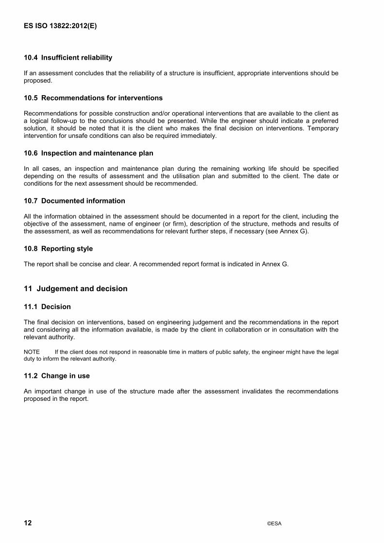
Annex A (informative)
Hierarchy of terms
ISO 13822:201 (E)
14
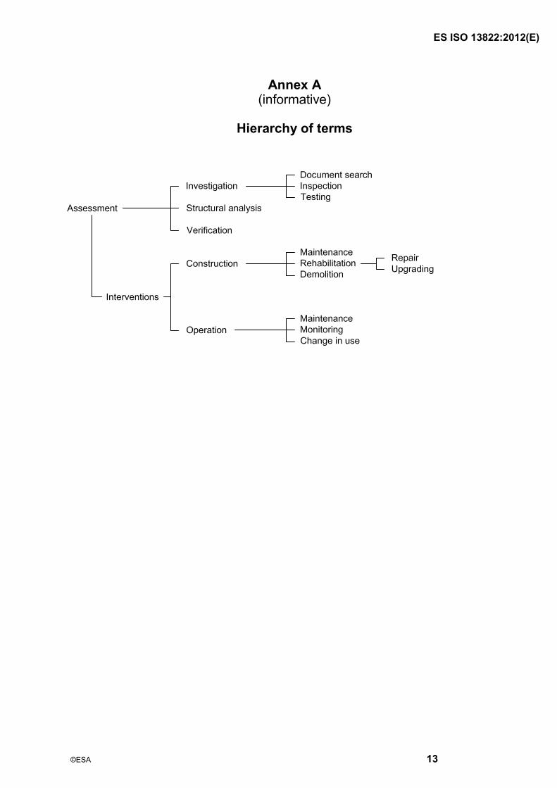
Annex B (informative)
Flowchart for the general assessment of existing structures
ISO 13822:201 (E)
15
Annex C (informative)
Updating of measured quantities
C.1 Types of inspection
C.1.1 An investigation of an existing structure is intended to update the knowledge about the condition (state) of the structure with respect to a number of aspects. Often, the first impression of the condition of a structure is based on a qualitative inspection. The description of possible damage of the structure is in verbal terms like �“none�”, �“minor�”, �“moderate�”, �“severe�”, �“destructive�”, �“unknown�”. Decisions based on such observation are made in a purely intuitive way by experts. A better judgement on the structure can be made on the basis of quantitative inspections that characterize the current properties of the structural components. For all inspection techniques, one should have information on the probability of detecting damage, if present, and on the accuracy of the results.
C.1.2 Proof loading or load testing is a special kind of quantitative inspection. The purpose may be to prove that a particular structural component is fit for use. It can also be desired to get indications of a larger group of components. For further information, see Annex D.
C.1.3 Also, investigations of actions can help in the assessment. The investigation depends on the type of actions. For permanent actions, such as the weight of the structure itself, dimensions and/or densities should be measured. For offshore structures, one can check the local wave climate. For wind actions on structures of special shape, the shape coefficients can be measured in a wind tunnel. For industrial loads, measurements can indicate differences from the original design assumptions. Of course, one should be careful; actions in codes are intended to represent the maximum in, say, 50 year values, which can be measured directly.
C.2 Evaluation of inspection results
C.2.1 Given the result of an investigation, there is a requirement to update the properties and reliability estimates of the structure. Two different methods can be distinguished:
a) direct updating of the structural failure probability;
b) updating of the (multivariate) probability distribution of the random variables.
The second method can be used to derive updated design values for use in the partial-factor format and for comparing directly with limit values (cracks, displacements).
When evaluating the inspection results of a certain structural member, it should be kept in mind that these results can also affect the reliability of other members or even members of other structures. For instance, the detection of cracking or corrosion in one member makes the presence of cracks and corrosion in other similar members more likely.
C.2.2 Direct updating of the structural failure probability [C.2.1 a)] can formally be carried out using the basic relationship from probability theory given in Equation (C.1):
{ }{ | } { }
P F IP F I
P I"= (C.1)
where
F designates a local or global structural failure;
ISO 13822:201 (E)
16
I designates the inspection information, for instance �“the fatigue crack at joint B is smaller than the detection limit�”;
indicates the intersection of two events;
| indicates �“conditional upon�”.
The denominator P{I} in Equation (C.1) is a normalizing constant, which follows from Equation (C.2):
P{F | I} + P{S | I} = 1,0 (C.2)
where S stands for �“non-failure�” or �“survival�”.
C.2.3 The updating procedure of the multivariate or individual probability distributions [C.2.1 b)] is given formally by Equation (C.3):
fX(x| I ) = C P{ I | x} fX(x) (C.3)
where
X is a basic variable or statistical parameter;
I is an inspection result [as in Equation (C.1)];
fX(x) is the probability density of X before updating;
C is a normalising constant;
fX(x | I ) is the probability density of X after updating with information I;
P{ I |x} is the likelihood to find information I for given value x of X.
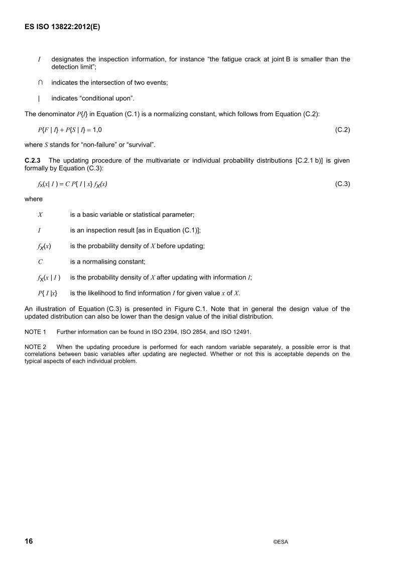
An illustration of Equation (C.3) is presented in Figure C.1. Note that in general the design value of the updated distribution can also be lower than the design value of the initial distribution.
NOTE 1 Further information can be found in ISO 2394, ISO 2854, and ISO 12491.
NOTE 2 When the updating procedure is performed for each random variable separately, a possible error is that correlations between basic variables after updating are neglected. Whether or not this is acceptable depends on the typical aspects of each individual problem.
ISO 13822:201 (E)
17
Key 1 initial distribution 2 updated distribution
Figure C.1 �— Original and updated probability density function for an inspected variable X
C.2.4 Once updated distributions for the basic variables in the structure have been found, one can calculate the updated failure probability P{F|I} by performing a probabilistic analysis. A more practical procedure is to determine updated design values for each random variable. For a resistance parameter X, the design value can be obtained from Equation (C.4) for a normal random variable and from Equation (C.5) for a lognormal random variable(see ISO 2394):
xd = µ (1 # $% V) (C.4)
xd = µ exp(#$% & # 0,5& 2) (C.5)
where
xd is updated design value for X;
µ is updated mean value;
$ is probabilistic influence coefficient;
% is target reliability index;
V is updated coefficient of variation;
& 2 is equal to ln(1 + V2).
The value of the target reliability index % is discussed in Annex F; the values of $ can be taken as equal to those commonly used for new structures (0,7 for the dominating load parameter; 0,8 for the dominating resistance parameter; and 0,3 for non-dominating variables in accordance with ISO 2394).
ISO 13822:201 (E)
18
As an alternative procedure, one can also determine first a characteristic value, xk, using Equation (C.6) for a normal random variable and Equation (C.7) for a lognormal random variable, and calculate the design value by applying the appropriate partial factor ' m as given in Equation (C.8)
xk = µ (1 # kV) (C.6)
xk = µ exp(#k& # 0,5& 2) (C.7)
xd = xk /' m (C.8)
The value k = 1,64 is usually used. It can be helpful to consider both methods and to use the most conservative result.
For loads and geomechanical properties, a similar procedure may be applied, but usually other distribution types are more appropriate.
After the evaluation of the updated design values, one may check the structural reliability using the standard procedure for new structures. It should be verified that, based on the design material and geometrical properties, no relevant limit state is reached when the design actions are applied to the structure.
C.3 Example
The idea behind this example is based on the testing procedure for timber for new structures. The example is presented only as an illustration of the theory. Equations and numbers have been highly simplified. It should be noted that, in particular for deteriorated structures, it is necessary to choose the data with much care.
Consider a simply supported timber beam loaded by a point load, Q, in its mid-span. The safety margin for such a beam is given by Equation (C.9)
S 4M Wf QL= # (C.9)
The designation of all variables and the numerical values used in this example are presented in Table C.1. All random variables are assumed to be normally distributed.
Table C.1 �— Data used in example
X Designation Unit Mean c.o.v. Value of xk
L Span metres 4 �— 4
W Plastic section modulus cubic metres 0,0104 �— 0,0104
I Moment of inertia metres to the fourth power 0,0002 �— 0,0002
Q Load kilonewtons 100 0,2 100
f Material strength megapascals 20 0,15 15
E Modulus of elasticity gigapascals 30 0,15 30
Failure of the beam corresponds to the event �“MS < 0�”. Using standard reliability techniques (see ISO 2394), one can evaluate a failure probability as P{MS < 0} = 0,0028. The corresponding reliability index is % = 2,77. This may be considered as being too low (see Annex F). For a semi-probabilistic judgement of the reliability, one can use the characteristic values in the last column of Table C.1. The standard requirement is as given by Equation (C. 10):
k F k
m 4Wf Q L''
> (C.10)
ISO 13822:20 (E)
19
where
'm is the partial resistance factor;
' F is the partial load factor.
Substituting 'm = 1,2 and ' F = 1,5 into Equation (C.10) one obtains the following values:
k
m
(0,010 4) (15)1,2
0,130 MNm130 kNm
Wf'
=
==
(C.11)
F k (1,5) (100) (4)4 4
150 kNm
Q L' =
= (C.12)
Therefore, the timber beam considered in this example does not satisfy the requirement expressed by Equation (C.10).
Next, assume that the beam is proof loaded by a deterministic load, Qt = 50 kN, and that a deflection of 9 mm be measured. According to the theory of elasticity, the deflection is given by Equation (C.13)
u = Qt L3/48EI (C.13)
which means that, equivalently, E may be estimated as in Equation (C.14):
E = Qt L3/48Iu (C.14)
= (50)(43)/(48)(0,0002)(0,009)
= 37 GPa
This indicates that the beam is stiffer than average. Since for timber, stiffness and strength show a positive correlation, this test result also indicates a more reliable resistance. Let the correlation between E and f be quantified as (E,f = 0,5. Using standard equations from the theory of the multi-dimensional normal distribution, one can derive an �“updated�” mean and standard deviation for the strength f as given in Equations (C.15) and (C.16) respectively:
37 GPa ,37
37 3020 (0,5) (3,0)4,5
22 MPa
Ef E f ff E
E
µµ µ ( &&=#= +
#= +
=
(C.15)
237 GPa ,1
2,6 MPaf E ff E& & (= = #
= (C.16)

ISO 13822:201 (E)
20
Given the updated distribution for f, one can calculate the failure probability, P{MS < 0|test result}, as being 0,000 08 corresponding to % = 3,76, which may be considered as sufficient. In a partial factor verification, one can update the characteristic value for f as given in Equation (C.17):
k test result test result1,64
22 (1,64)(2,6)18 MPa
f ff µ &= #
= #=
(C.17)
This raises Wfk/'m from 130 kNm to 153 kNm, which is also sufficient. It should be noted that the updating given by Equation (C.15) and (C.16) is valid only for the considered beam.
ISO 13822:201 (E)
21
Annex D (informative)
Testing for static and dynamic properties of structures
D.1 Objectives
D.1.1 Many kinds of field testing are useful for assessment of static and dynamic properties of existing structures (e.g. a horizontal loading test or a forced vibration test of a complete structure, a vertical loading test or a forced vibration test of components of a structure, a horizontal or vertical micro-tremor measurement of a structure). Load testing of a complete structure is costly and time-consuming. However, there can be some structures that are not amenable to calculation. In such cases, the only way to assess the properties of the structure is to carry out field tests.
D.1.2 Testing for the static and dynamic properties of structures may be selected as a part of an assessment provided there is a satisfactory reason, such as the following.
a) The testing is useful in providing additional evidence including cases when deterioration of structural components has occurred, when there is a change of use, or when construction has not been carried out in accordance with the design drawings and specifications.
b) When calculations cannot be completed with confidence, load testing and vibration testing can provide an improved understanding of the actual behaviour of the structure, which cannot be obtained in any other way.
c) Structural components forming part of an existing structure behave differently from the behaviour assumed during the design.
D.1.3 Testing for static and dynamic properties of structures should have clear objectives. Examples of the objectives are
a) to predict directly the ultimate resistance or to establish serviceability properties of structural parts,
b) to obtain specific material properties,
c) to examine the behaviour of existing structures or structural components,
d) to identify system parameters used for verification of analysis, such as fundamental period, damping factor, and
e) to evaluate the load bearing capacity of structure by a specific load test, i.e. proof loading.
D.1.4 Testing for static and dynamic properties of the structures may be selected if the following conditions are met.
a) The testing is conducted in such a manner as to prevent sudden and uncontrollable collapse during the test.
b) Load sharing among structural components should be taken into consideration. Load sharing can occur such that adjacent components also act in resisting the applied load when a single component is loaded. Load sharing also influences the dynamic properties of the structure.
c) It is important in the load testing and vibration testing that the structure be exposed and accessible for visual inspection before, during and after the test.
d) The influence of temperature changes on the instrumentation should be considered.
ISO 13822:201 (E)
22
D.2 Test planning
D.2.1 Agreement to test plan
Prior to the execution of the testing, a test plan should be agreed with the client and testing organization. In the test plan, the objective of the test and all specifications necessary for the selection of the test specimens, and the execution of the tests and the test evaluation should be clearly stated. In particular, the plan of the test should include descriptions of the items described in D.2.2 to D.2.8.
D.2.2 Scope of test plan
Information required from the test should be clearly stated, for example the required properties, the influence of certain parameters varied during the test and the range of validity.
D.2.3 Expected behaviour
It is essential to present a description of all properties and circumstances that can influence the behaviour at the limit state under consideration, (e.g. geometrical parameters and their tolerances, material properties, scale effects and environmental influences). Modes of failure and/or calculation models with the corresponding variables should be described. When the prediction of the critical failure modes expected in the test is extremely doubtful, the test plan should be developed on the basis of accompanying pilot tests.
D.2.4 Specification of test specimen
The properties of the test specimen should be specified, in particular, the dimensions, sampling procedures and restraints. Normally, the aim should be for a representative sample in the statistical sense.
D.2.5 Static and dynamic loading and vibration specifications
Loading procedure and environmental influences in the test should be specified, in particular, loading points, loading paths in time and space, excitation locations, excitation forces, temperatures, loading by deformation or force control, etc. Loading paths and excitation forces should be selected such that they are representative for the anticipated scope of application of the structural component. Account should be taken of possible unfavourable effects of those actions that are considered in calculations in comparable cases. Interaction of actions with structural response should be considered where relevant.
D.2.6 Measurements plan
Prior to the execution of the test, a list should be made of all relevant properties of each individual test specimen, (e.g. time histories of displacements, velocities, accelerations, strains, forces and pressures, required frequency and accuracy of measurements and measuring devices). Similarly, a plan of observation points and methods for observation and recording should be made. Depending on the type of test, it is recommended to have some measurements available simultaneously during the test.
D.2.7 Testing arrangement
Special attention should be given to measures to ensure sufficient strength and stiffness of the loading and supporting rigs, and clearance for deflections, etc.
D.2.8 Consent
In all cases, consent should always be obtained from the client (owner, authority, insurance companies, etc.), and full consideration should be given to any possible adverse effects on the structure or occupants. The consent of local authorities can also be required.
ISO 13822:201 (E)
23
D.3 Evaluation of test results
D.3.1 The measurement of the static, dynamic or both properties obtained in the test should be compared with those predicted by analytical models. When a large deviation from the prediction occurs, the reason should be investigated and explained, involving additional tests if necessary.
D.3.2 Where relevant, the evaluation of test results should be on the basis of statistical methods. In principle, the test should lead to a statistical distribution for the pre-selected unknown variables, including the statistical uncertainties. Based on this distribution, design values, characteristic values and partial safety factors for use in partial coefficient design can be derived. Only the characteristic value can be derived while the partial factor is taken from normal design procedure.
D.3.3 If the test results depend on the load duration or history, amplitude of dynamic response, volume or scale, environmental influences, or other non-structural effects, the analytical model should take these items into account by use of appropriate factors, non-linearity and scaling rules.
D.3.4 When the test results are evaluated as valid, their extrapolation can be applied to cover other loading paths or excitation forces although this requires additional information (e.g. from experiences of previous tests or analytical studies).
D.4 Test report
It is recommended to report the test results using the content outlined in Annex G. It can be appropriate to report the test results separately or to put them in an annex to the main report.
ISO 13822:201 (E)
24
Annex E (informative)
Assessment of time-dependent reliability
E.1 Introduction
When assessing the reliability and remaining working life of existing structures, the effect of time variations both in the strength, due to, for example, deterioration, and the load characteristics should be taken into account. When only the load varies in time, the method described in ISO 2394 and Reference [3] may be used for the assessment. For time-variant reliability problems where the resistance is deteriorating and the loading is time invariant, the reliability assessment may be performed by considering the strength characteristics corresponding to the end of the working life of the structure. When both the strength characteristics and the load characteristics vary with time, the assessment requires special consideration as described in this annex.
E.2 Terms and definitions
For the purposes of this annex, the following terms and definitions apply.
E.2.1 load characteristics qualitative and quantitative description of load intensity, which can vary in time, such as the duration, interval, and occurrence rate of the load events and their intensity at any point in time
E.2.2 non-homogeneous random vector process X(t) random function of time such that for any point in time the values of the elements Xi of the vector are random variables
NOTE The statistical characteristics of Xi in a non-homogeneous random vector process vary with time.
E.2.3 strength characteristics qualitative and quantitative description of the strength of a structure or a structural component, which can vary in time, such as the mean value and standard deviation of strength
E.2.4 threshold limit value, which can be a function of time, beyond which a structure or a structural component is in an unfavourable state
E.3 Strength characteristics that vary slowly with time
E.3.1 When the strength is slowly deteriorating and the load characteristics vary with time, the reliability assessment in principle can be addressed as a first passage problem of a non-homogeneous random vector process (see Reference [3]). Figure E.1 illustrates the process schematically. In spite of the simplicity of concept, considerable simplifications are needed in most practical applications.
ISO 13822:201 (E)
25
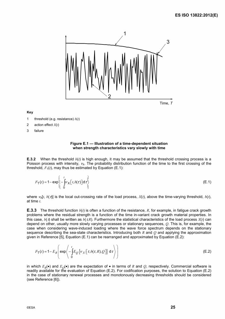
Key
1 threshold (e.g. resistance) b(t)
2 action effect X(t)
3 failure
Figure E.1 �— Illustration of a time-dependent situation when strength characteristics vary slowly with time
E.3.2 When the threshold b(t) is high enough, it may be assumed that the threshold crossing process is a Poisson process with intensity, )X. The probability distribution function of the time to the first crossing of the threshold, FT(t), may thus be estimated by Equation (E.1):
T X0
( ) 1 exp , ( ) dt
F t t b) * *= # # (E.1)
where )X[t, b(*)] is the local out-crossing rate of the load process, X(t), above the time-varying threshold, b(t), at time t.
E.3.3 The threshold function b(t) is often a function of the resistance, R, for example, in fatigue crack growth problems where the residual strength is a function of the time in-variant crack growth material properties. In this case, b(*) shall be written as b(*,R). Furthermore the statistical characteristics of the load process X(t) can depend on other, usually more slowly varying processes or stationary sequences, Q. This is, for example, the case when considering wave-induced loading where the wave force spectrum depends on the stationary sequence describing the sea-state characteristics. Introducing both R and Q and applying the approximation given in Reference [5], Equation (E.1) can be rearranged and approximated by Equation (E.2):
{ }T0
( ) 1 exp , ( , ), dt
R Q XF t E E b R Q) * * *= # # (E.2)
in which ER(•) and EQ(•) are the expectation of • in terms of R and Q, respectively. Commercial software is readily available for the evaluation of Equation (E.2). For codification purposes, the solution to Equation (E.2) in the case of stationary renewal processes and monotonously decreasing thresholds should be considered (see Reference [6]).
ISO 13822:201 (E)
26
E.3.4 When the hazard function, h(t), defined as the conditional probability of failure that failure occurs in the interval (t, t + dt], given that the structure has survived up to t is available, the probability distribution function of the time to failure can be expressed as given by Equation (E.3) (see Reference [4]):
T0
( ) 1 exp ( )dt
F t h * *= # # (E.3)
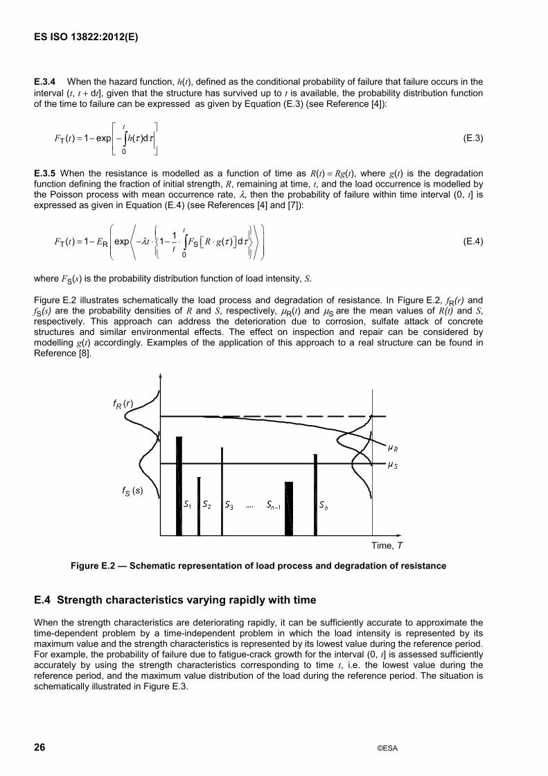
E.3.5 When the resistance is modelled as a function of time as R(t) = Rg(t), where g(t) is the degradation function defining the fraction of initial strength, R, remaining at time, t, and the load occurrence is modelled by the Poisson process with mean occurrence rate, +, then the probability of failure within time interval (0, t] is expressed as given in Equation (E.4) (see References [4] and [7]):
T R S0
1( ) 1 exp 1 ( ) dt
F t E t F R gt
+ * *= # # , # , , (E.4)
where FS(s) is the probability distribution function of load intensity, S.
Figure E.2 illustrates schematically the load process and degradation of resistance. In Figure E.2, fR(r) and fS(s) are the probability densities of R and S, respectively, µR(t) and µS are the mean values of R(t) and S, respectively. This approach can address the deterioration due to corrosion, sulfate attack of concrete structures and similar environmental effects. The effect on inspection and repair can be considered by modelling g(t) accordingly. Examples of the application of this approach to a real structure can be found in Reference [8].
Figure E.2 �— Schematic representation of load process and degradation of resistance
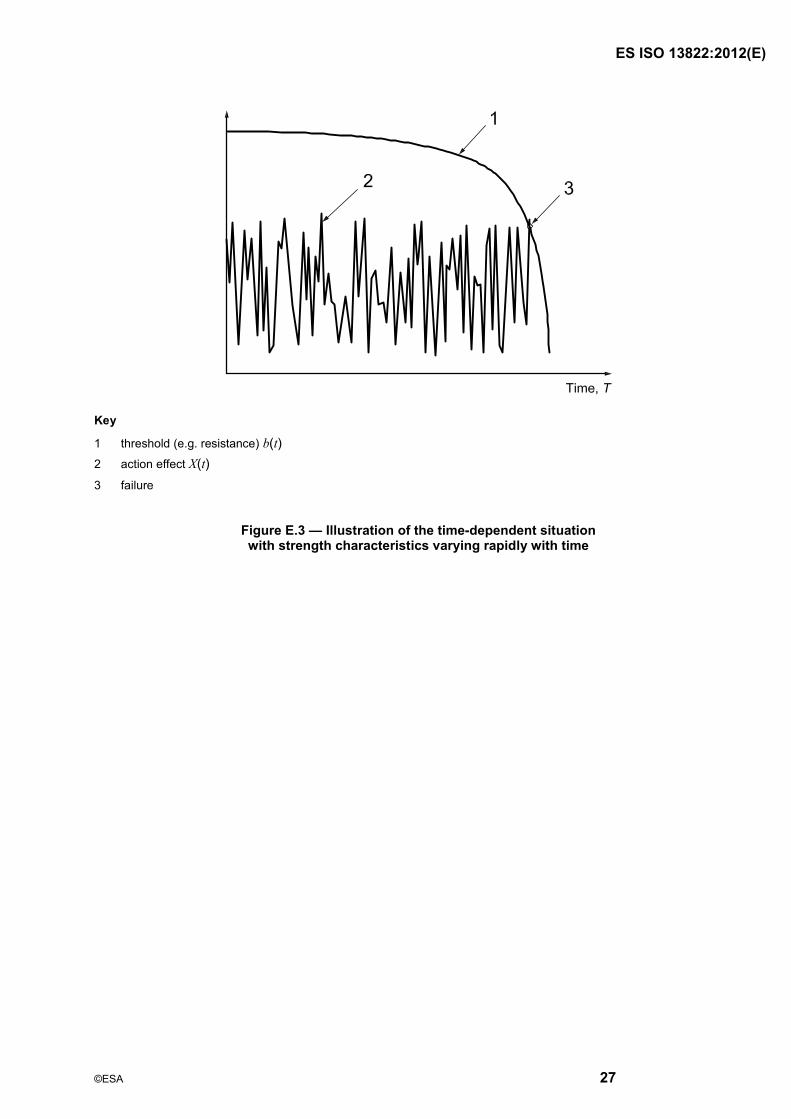
E.4 Strength characteristics varying rapidly with time
When the strength characteristics are deteriorating rapidly, it can be sufficiently accurate to approximate the time-dependent problem by a time-independent problem in which the load intensity is represented by its maximum value and the strength characteristics is represented by its lowest value during the reference period. For example, the probability of failure due to fatigue-crack growth for the interval (0, t] is assessed sufficiently accurately by using the strength characteristics corresponding to time t, i.e. the lowest value during the reference period, and the maximum value distribution of the load during the reference period. The situation is schematically illustrated in Figure E.3.
ISO 13822:201 (E)
27
Key
1 threshold (e.g. resistance) b(t) 2 action effect X(t) 3 failure
Figure E.3 �— Illustration of the time-dependent situation with strength characteristics varying rapidly with time
ISO 13822:201 (E)
28
Annex F (informative)
Target reliability level
F.1 General
The structure should be adequately modelled and the limit state functions should be clearly defined in order to determine the reliability requirements.
The target reliability level used for verification of an existing structure can be determined based on calibration with the current code, the concept of the minimum total expected cost, and/or the comparison with other social risks. The requirements should also reflect the type and importance of the structure, possible failure consequences and socio-economical criteria.
Although in ISO 2394 the performance requirements of safety and serviceability for the assessment of existing structures are, in principle, the same as for the design of new structures, there are some fundamental differences between these two activities affecting the differentiation in structural reliability, namely the following.
a) Economic considerations: The incremental cost between acceptance and upgrading the existing structure can be very large, whereas the incremental cost of increasing the safety of a structural design is generally very small, consequently conservative generic criteria are used in design standards.
b) Social considerations: These include disruption (or even displacement) of occupants and activities, also heritage values, considerations that do not affect the structural design of new structures.
c) Sustainability considerations: Reduction of waste and recycling, considerations of less importance in the design of new structures
As a consequence the goal of �“minimum structural intervention�”, which makes as much use as possible of the existing materials in the structure, applies for most existing structures of normal occupancy and use.
F.2 Reliability requirements
F.2.1 Reliability requirements for an existing structure, as well as for a new structure, may adequately be expressed in terms of the reliability index, %, where % is defined as given in Equation (F.1):
% = #- #1(Pf) (F.1)
where
- (.) is the standard normal probability distribution function;
Pf is the failure probability corresponding to a specified reference period.
The remaining working life determined at the assessment is considered as a reference period for an existing structure for serviceability and fatigue, while design working life is often considered as a reference period for a new structure. A shorter reference period can be reasonable for the ultimate limit states. The target reliability indices may be chosen in accordance with the current codes, if such are provided, otherwise the values given in Table F.1 are intended as illustrations for assessment of existing structures (see ISO 2394:1998, E.4).
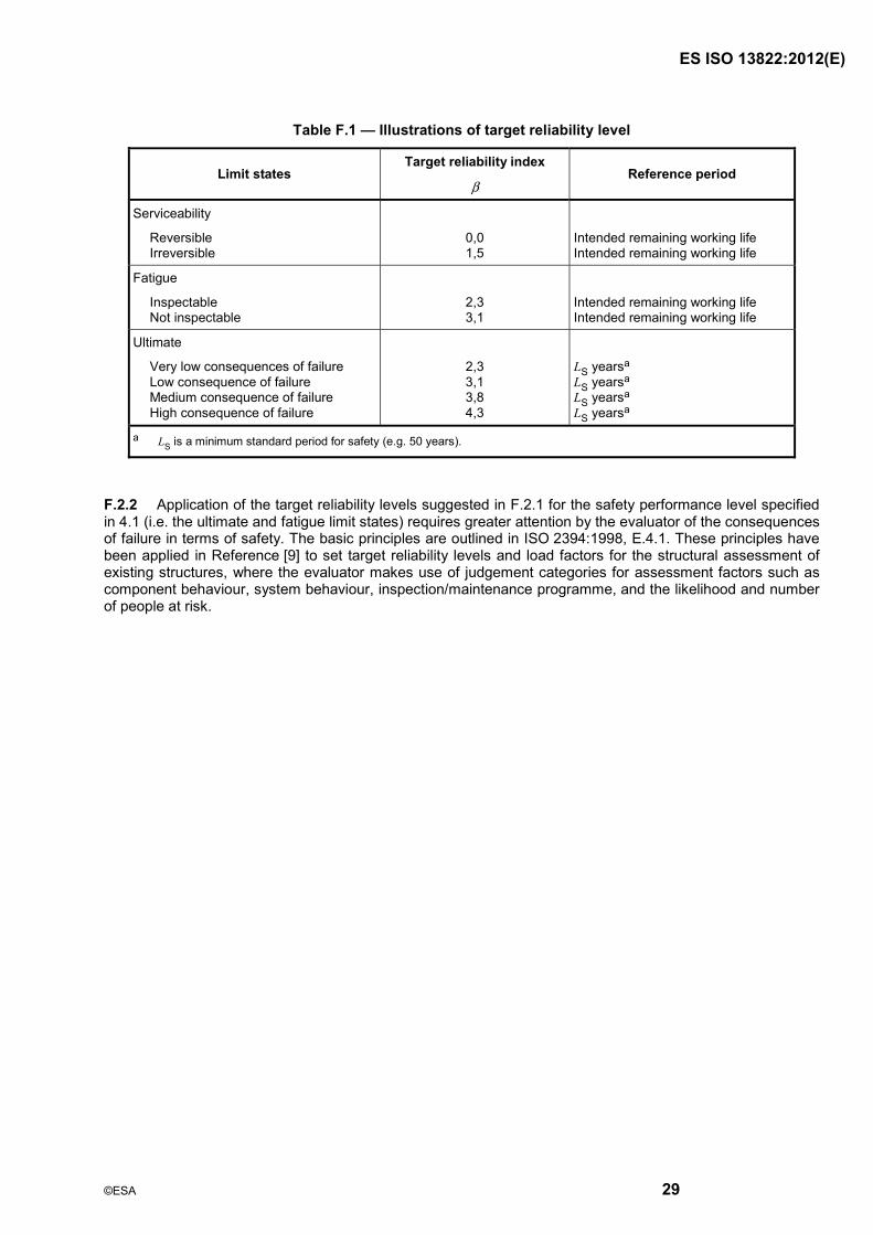
ISO 13822:201 (E)
29
Table F.1 �— Illustrations of target reliability level
Limit states Target reliability index
% Reference period
Serviceability
Reversible Irreversible
0,0 1,5
Intended remaining working life Intended remaining working life
Fatigue
Inspectable Not inspectable
2,3 3,1
Intended remaining working life Intended remaining working life
Ultimate
Very low consequences of failure Low consequence of failure Medium consequence of failure High consequence of failure
2,3 3,1 3,8 4,3
LS yearsa LS yearsa LS yearsa LS yearsa
a LS is a minimum standard period for safety (e.g. 50 years).
F.2.2 Application of the target reliability levels suggested in F.2.1 for the safety performance level specified in 4.1 (i.e. the ultimate and fatigue limit states) requires greater attention by the evaluator of the consequences of failure in terms of safety. The basic principles are outlined in ISO 2394:1998, E.4.1. These principles have been applied in Reference [9] to set target reliability levels and load factors for the structural assessment of existing structures, where the evaluator makes use of judgement categories for assessment factors such as component behaviour, system behaviour, inspection/maintenance programme, and the likelihood and number of people at risk.
ISO 13822:201 (E)
30
Annex G (informative)
Test report format
G.1 Title page
The following items should be stated: title; date; client; and author (full name and address of engineer and/or firm).
G.2 Name of engineer and/or firm
The names of the people who carried out the assessment should be stated, together with those of the client's representatives and others who were in attendance.
G.3 Synopsis
One, or at most two pages, in plain, succinct language, should be used to summarize the problem, the significant features of investigations carried out, and the principal conclusions and recommendations, including any important reservations and/or exclusions.
G.4 Table of contents
The following should be included:
a) scope of assessment;
b) description of the structure;
c) investigation:
! document examined,
! inspection items,
! sampling and testing procedure,
! test results;
d) analysis;
e) verification;
f) discussion of evidence;
g) review of intervention options;
h) conclusions and recommendations;
i) reference documents and literature;
j) annexes.
ISO 13822:201 (E)
© ISO 2010 �– All rights reserved 31
G.5 Scope of assessment
This should specify the reasons for the assessment and the scope of the work, as agreed between the client and the engineer. The procedure for the assessment should be described (see Annex B), and all activities for the assessment should be reported. The utilization plan and the safety plan should be specified.
G.6 Description of the structure
The following items should be described: name, address and structural system, together with any drawings. This should be made brief and pictorial. Also, a history of the structure's original construction, subsequent alterations, past and present use should be given.
G.7 Investigation
G.7.1 Documents examined
The documents made available to the engineer should be listed, together with their source (e.g. clients' or solicitors' letters, drawings and/or reports by others, sent by the client).
G.7.2 Inspection items
It can be important to make it clear that an adequate number of inspections were made by adequately qualified people. Any limitations on the effectiveness of the inspections, due to circumstances beyond the engineer's control, should be indicated.
G.7.3 Sampling and testing procedure
The nature and number of samples taken on each occasion and the dates when such samples were taken should be stated together with the location where they were taken. The name of the laboratory should be given, together with the contractual arrangements for sampling and testing. The purpose and nature of the tests/analyses should be stated, followed by a resume of the results. Copies of the laboratory reports should be provided as an annex. In a case of load testing, the test plan and other documents should be provided in an annex.
G.8 Analysis
The type of calculation carried out and the criteria against which the results have been judged should be stated. The findings should be summarised. Detailed calculations may be reproduced in an annex.
G.9 Verification
The verification of structural safety and serviceability should be carried out as described in Clause 7.
G.10 Discussion of evidence
As the heading indicates, this is the item under which one discusses the importance of each of the findings described under G.11 and G.12, and, in particular, their relevance to the objectives of the assessment. Any uncertainties remaining after the investigation and any needs for further checks should be stated here.
ISO 13822:201 (E)
32
G.11 Review of intervention options
The possible options of interventions should be reviewed. The estimated cost associated with each of the options may be provided.
G.12 Conclusions and recommendations
G.12.1 Conclusions
These should be firm and reasoned judgements reached after careful assessment of the information obtained. It is prudent to discuss briefly the accuracy and limitations of the methods employed and the true significance of the findings. Every conclusion should be based on matters contained in the preceding sections of the report.
G.12.2 Recommendations
Courses of action that are available to the client as a logical follow-up to the conclusions should be briefly described. Brief ideas about the cost for the courses should also be given. The remaining working life, inspection and maintenance planning and next date for assessment should be specified.
G.12.3 Annexes
The following items should be provided: drawings, photographs, laboratory reports, calculations, etc.
ISO 13822:201 (E)
33
Annex H (informative)
Design of upgrading
H.1 Reasons for upgrading
Intervention for upgrading may be carried out for a number of reasons including the following:
a) strengthening to improve the ultimate limit state performance of specific structural elements or the overall structure;
b) enhancement of some aspect of elemental or overall serviceability performance;
c) remedies to compensate for the effects of current or anticipated structural deterioration;
d) preventive measures to avoid or minimize future structural deterioration.
NOTE Upgrading is outside the scope of this International Standard. This informative annex is included for completeness of the coverage.
H.2 Methods of upgrading
There are a variety of ways by which interventions for upgrading can be implemented. An individual scheme may utilize a combination of methods to achieve different objectives. These include the following generic approaches:
a) modification of structural capacity or some other structural performance parameter of specific structural elements or the overall structure (e.g. increase in section size by overlay or application of additional material, provision of supplementary reinforcement, plate bonding or introduction of prestressing);
b) introduction of additional structural components (e.g. provision of a supplementary structural frame or members to reduce the proportion of the current or future actions carried by the existing structure, introduction of stay cables or external stressing altering the load path);
c) modification of boundary conditions or methods of support (e.g. fixing joints to provide structural continuity, introducing joints);
d) application of coatings, membranes or some other types of barrier for modifying local environmental influences (e.g. by means of over-cladding, insulation or another form of enclosure) to minimize future deterioration and so enhance durability.
H.3 Design of upgrading
H.3.1 It is necessary that the objectives of an individual scheme be clearly identified, together with any associated constraints that can affect the choice of methodology for implementing the upgrading. It is essential to ensure that sufficient information is available to enable undertaking the design of the upgrade with confidence. It can be necessary to obtain additional information to supplement that obtained during earlier phases of the assessment process.
H.3.2 It is generally necessary to assess structural performance for the ultimate limit states. However, it can be necessary to give consideration to the performance for the appropriate serviceability limit states, as well as for structural integrity, the effects of fire, durability, time-dependent behaviour and measures required to ensure that additions or modifications to the structure act effectively with the existing structural elements.
ISO 13822:201 (E)
34
H.3.3 The choice of a particular upgrading method usually depends on the special circumstances relating to the use of the structure in question. Design of the proposed intervention is generally an iterative process. The proposed intervention normally is expected to be sympathetic to the nature and form of the existing structure, taking account of any special architectural or heritage perspectives. In addition to technical and engineering matters, it is also often necessary to compare for the various upgrading options on the basis of a cost-benefit evaluation over the anticipated remaining working life of the structure.
H.3.4 The performance of an existing structure that has experienced appreciable deterioration can differ significantly from that of the original structure. Severe deterioration can affect structural performance in a number of ways, for example reducing ductility and altering the failure mode at the ultimate limit state.
H.3.5 Relative stiffness and time-dependent effects often influence the degree of load sharing between existing and new structural elements. Structural modifications can also change the path by which actions are transferred through the structure. It is essential that due account be taken of this and that appropriate evaluations be made of all structural elements forming the load path to the foundations.
H.4 Planning, phasing and control of upgrading works
H.4.1 The type of intervention depends on the function of the structure and structural elements concerned, with different approaches often being employed for elements acting in compression, tension or bending.
H.4.2 Planning of the upgrading construction process, including the provision of temporary supports, should be carried out in co-operation with all parties to ensure the stability and integrity of the structure during all phases of construction. Deviations from the planned process should be evaluated by the designer of the upgrading to ensure that the stability and integrity of the structure is maintained at all times. The designer works should seek to anticipate any significant changes that can potentially arise in the stability and robustness of the structure as the works are undertaken. The essence of this information should be conveyed to those responsible for undertaking the works. In programming the upgrading works, the designer should recognize important divisions in the work and identify periods or phases of work that can involve particular hazards. Deviations from the planned sequence of working should be carefully evaluated to assess any structural implications that they can have.
H.4.3 It can also be necessary to implement some form of structural monitoring as a means of assisting in the control and management of the upgrading works. A special monitoring system can be necessary where complex and involved structural works are being undertaken. It is essential that sufficient resources are applied not only to factors such as instrumentation requirements, but also to factors associated with processing and interpretation of the data, and the management of the information from the monitoring system.
H.5 Other considerations
H.5.1 It is necessary that any proposed upgrading works comply with relevant health and safety guidelines and related statutory requirements. These can not only apply to the construction process, but also possibly impose wider duties in relation to the general public. Consideration should also be given to materials in the existing structure (e.g. asbestos-based products, etc.) that can be disturbed by the proposed upgrading.
H.5.2 Consideration should be given to disruptions in the use of the structure associated with a particular intervention methodology.
H.5.3 A quality plan should be established for the proposed upgrading, while giving consideration to all processes and actions concerned with its design and implementation. All processes requiring documented procedures should be identified with separate identification of those processes, the results of which cannot be verified by subsequent inspection and testing of the product. Actions that it is necessary to take with respect to non-conforming product should be specified, together with subsequent corrective actions which should be implemented.
ISO 13822:201 (E)
© 35
Annex I (informative)
Heritage structures
I.1 Introduction
The purpose of this annex on heritage structures is to provide additional considerations for the application of this International Standard to heritage structures. This annex shall be read in conjunction with all of the sections of this International Standard.
This annex is based on the premise that a structure can have cultural and heritage value in itself. Heritage structures should be preserved for their own sake and not merely as supports for the rest of the historic material. It follows that the integrity of the existing structure should be respected during any intervention.
NOTE Discussion of these issues is provided in References [10] to [14].
I.2 Fundamentals
I.2.1 Assessment of heritage structures
The assessment of a heritage structure includes two aspects: that concerning its structural performance, familiar to engineers, and that concerning its value as a cultural resource. These two aspects shall both be taken into account in any decision involving possible structural interventions and should therefore be carried out in tandem.
I.2.2 Heritage value
The heritage value of an historic structure resides in the authenticity and integrity of its character-defining elements. To retain authenticity and integrity, the structure shall be preserved, as far as possible, with its original materials and structural concept.
NOTE 1 The structure itself often represents an important aspect of the culture of its period: the construction knowledge, technology, and skills of a given time represent a legacy to future generations. There are numerous examples of exceptional heritage structures while other heritage structures are typical structural designs of their time, but nonetheless are critical to the cultural resource in their supporting role to other character-defining elements, such as architectural material or paintings.
NOTE 2 Judgments about heritage value and authenticity can differ from culture to culture, and thus, there are no fixed criteria. In some geographical areas, keeping alive traditional construction practice is privileged over the conservation of original materials.
I.2.3 Limitation of structural intervention
An over-cautious approach to structural assessment should be avoided because it can lead to unnecessary structural interventions and result in loss or major alteration of heritage character-defining elements and, ultimately, in the loss of authenticity and historic significance of the cultural resource. Furthermore, excessive scope of intervention can add unnecessary cost and compromise the viability of a conservation project, and eventually jeopardize the existence of a cultural resource.
NOTE In the case of historic resources, the commemorative integrity of an historic site can be threatened by unjustified structural interventions.
ISO 13822:201 (E)
36
I.3 Terms and definitions
For the purposes of this annex the following terms and definitions have been added, supplementing those in the core document, to reflect activities related to heritage structures.
I.3.1 character-defining elements historic materials, forms, locations, spatial configurations, morphology, concept and details, structural design, uses and cultural associations that contribute to the heritage value of a structure that shall be retained in order to preserve its heritage value
NOTE 1 Some elements of the structure have significance because they provide evidence of ancient construction technologies and skills. In such cases, they can be classed as character-defining elements.
NOTE 2 Significant subsequent historic changes and alterations, imperfections and damage can be identified as character-defining elements, and are to be respected provided that they do not compromise the safety requirements.
I.3.2 conservation all actions or processes that are aimed at safeguarding the character-defining elements of a cultural resource so as to retain its heritage value and extend its physical life
NOTE 1 Several words are used over the world to describe the action and process of safeguarding and extending the life of a cultural resource: conservation, preservation, and restoration. Conservation has been used by UNESCO and World Heritage.
NOTE 2 Conservation is composed of a variety of intervention activities (shown in Annex A) depending on the character-defining elements in which the respect for heritage value is an important consideration.
I.3.3 cultural resource structure, building, landscape, archaeological site, or other engineering works, that have been formally recognized for its heritage value
I.3.4 heritage documents any pre-existing documents related to the heritage structure
I.3.5 heritage record record made in the present to describe the existing states of the heritage structure
I.3.6 heritage structure existing structure or structural component of a heritage resource that has been recognized by the appropriate authorities for its heritage value
NOTE Heritage structures can include all kinds of buildings, bridges and civil engineering works including their foundations.
I.3.7 heritage value aesthetic, historic, scientific, cultural, social or spiritual importance or significance for past, present, and future generations and that should be embodied in its character-defining elements
I.3.8 historical report summary derived from heritage documents that identify the nature of the original construction process and technologies, all subsequent alterations and any significant events that have caused structural damage

ISO 13822:201 (E)
37
I.3.9 incremental approach step-by-step procedure in which the behaviour of the structure is monitored at each step and the acquired data are then used to provide the basis for further action
I.3.10 minimal intervention intervention that balances safety requirements with the protection of character-defining elements, ensuring the least harm to heritage values.
I.4 General framework of assessment
I.4.1 Objectives
In the case of heritage structures, the special performance levels mentioned in 4.1 c) shall include the conservation of the heritage value and character-defining elements. This performance level is attained through minimal intervention as defined in I.3.10.
The required structural performance shall be consistent with objectives listed in 4.1 of the core document:
a) safety performance level for the users;
b) serviceability performance level related also to the protection of the cultural resources.
I.4.2 Procedure
For heritage structures the procedure listed in 4.2 is appropriate provided that the particularities listed in I.4.3 to I.4.6 are taken into consideration.
Structural assessment for heritage structures should be generally carried out in collaboration with a multi-disciplinary team that includes specialists, such as engineers (structural, geotechnical, etc.), architect, landscape architect, heritage recorder, archaeologist, historian, cultural resource manager, interpreter, material scientist, conservator, geophysicist, etc. While the structural engineer should deliver a specific structural evaluation report, the ramifications of this report should be discussed within the multi-disciplinary team and decision generally reached by consensus.
I.4.3 Specification of assessment objectives
A precise specification of investigative procedures and analysis is often impossible at the outset and the agreement between the client and engineer shall allow for revisions and extensions as required.
I.4.4 Preliminary assessment
I.4.4.1 Scope
Preliminary assessment shall be carried out to identify possible problems requiring urgent intervention and to plan the detailed assessment. The preliminary assessment shall be carried out within the frame of the multidisciplinary team of experts and should consider, as far as possible, available heritage documents.
I.4.4.2 Preliminary inspection
When essential for the preliminary assessment, the possibility of inspection by opening up of the structure or, preferably, by non destructive testing (NDT) or minor destructive testing (MDT) can be considered. The engineer shall consult with the relevant heritage professionals to obtain approval prior to any opening up.
ISO 13822:201 (E)
38
I.4.4.3 Monitoring
Monitoring by means of simple devices should be considered as measures to detect possible active problems requiring immediate actions. Monitoring during preliminary assessment can contribute to the planning of later monitoring during detailed assessment.
I.4.4.4 Preliminary checks
In addition to the safety and serviceability of the structure as stated in the body of this International Standard, the preliminary check should also identify critical deficiencies related to the conservation of character-defining elements.
I.4.4.5 Immediate actions
In addition to the immediate actions described in 4.5.4, when character-defining elements are in immediate danger this should be reported to the client and to any heritage resource manager. Any interim interventions necessary to ensure the stability of the structure shall not cause damage to heritage character.
I.4.4.6 Recommendations for detailed assessment
Recommendations for detailed assessment should be made when there is evidence that character-defining elements may be endangered in the long term.
I.4.5 Detailed assessment
I.4.5.1 Scope
The scope of the detailed assessment shall be defined by the preliminary assessment, which shall identify those aspects of either the history or the properties of the structure that cannot be adequately described at the preliminary stage.
I.4.5.2 Historical report
An historical report for heritage structures is essential. This should identify the nature of the original construction, all subsequent alterations and any significant events that have caused structural damage. In general, cultural resource specialists (such as historians or archaeologists) should be employed to produce this report. The engineer shall assist them in the identification and interpretation of structurally meaningful documents. Where no such specialist is employed, the engineer should include historical information in their assessment report and, therefore, be responsible for the identification and interpretation of heritage documents.
NOTE Historical reports are not produced for structural purposes. They generally provide useful information, but as they can also be misleading and contain information difficult to interpret, it is necessary that they be carefully evaluated.
I.4.5.3 Detailed documentary search and review
In addition to the activities listed in the core document, a history of the use of the heritage structure affecting its past environmental conditions should be documented. As well as visual inspection, this may need to draw upon such sources as oral history, historic photographs, as well as maintenance or other records.
I.4.5.4 Heritage record
Heritage records shall be produced by specialists. This should normally be carried out before the detailed assessment or during the preliminary assessment.
Records should be made in such a way that they can be used as the basis for reporting structural condition observations, structural modelling and for conceptual design drawings of construction interventions.
ISO 13822:201 (E)
39
I.4.5.5 Detailed inspection
A detailed visual and tactile inspection should be carried out. Representative samples of hidden elements should be inspected. Openings should be carried out in stages, step-by-step only when analysis indicates that further openings are necessary. The potential gain in information obtained by either dismantling or opening to access hidden features shall outweigh the loss of heritage value.
Dismantling and rebuilding to ascertain the capacity of hidden elements may be carried out
a) if it is recognized by the cultural heritage management authorities as part of the traditional method for repair and maintenance, or
b) if it is absolutely necessary to ensure safety and serviceability.
I.4.5.6 Sampling
Samples taken for materials testing should be kept to a minimum and generally restricted to those parts of the structure that have the least heritage value.
I.4.5.7 Preferred testing methods
NDT and MDT should be used. Historic structural assemblies are typically complex and non-homogeneous. NDT tests should be carried out by qualified specialists, assisted by the engineer or heritage professional, to ensure proper calibration of instrumentation and interpretation of the results. In some cases, destructive tests can be necessary to calibrate NDT.
NOTE NDT and MDT aim to determine physical, mechanical and chemical characteristic of materials, in-situ stresses, mechanical properties of assemblies, and the presence of discontinuities. Recent developments in software and instrumentation have increased significantly the effectiveness of NDT.
I.4.5.8 Destructive testing
Destructive tests causing significant damage to character-defining elements should only be used when absolutely necessary, either to obtain information that cannot be acquired by other means or to calibrate NDTs, preferably in inconspicuous areas and without affecting character-defining elements. However, as described above, the potential gain in information obtained shall outweigh the loss of heritage value, i.e. the losses resulting from the tests should be less than those that would be caused by the more severe interventions necessitated by poorer understanding of the structure.
I.4.5.9 Monitoring
Monitoring shall be carried out to improve the understanding of the behaviour of the structure over time. Both structural and environmental parameters should be recorded to correlate causes and effects.
I.4.5.10 Determination of structural properties
Testing to determine the properties and/or load bearing capacity of the structure shall be planned in consultation with the heritage management professionals. The requirement for the test and any possible adverse effects on the heritage structures shall be clearly identified.
I.4.5.11 Structural analysis
Structural analysis should take into consideration the uncertainties resulting from
a) incomplete data,
b) greater age factors,
c) damage and deformation,
ISO 13822:201 (E)
40
d) limited knowledge of ancient structural systems, and
e) variability of material properties.
Therefore, it can be necessary to consider more than one structural model. When the models fail to demonstrate sufficient reliability of the structure, it can be necessary to carry out additional testing of materials and structural properties or monitoring, incorporating the results in a revised structural analysis.
NOTE The information gained through this incremental procedure can be used to gradually improve the understanding and modelling of the structure.
I.4.5.12 Verification
The reliability level for verification on heritage structure shall balance safety and serviceability considerations with the protection of heritage value.
I.4.6 Results of assessment
I.4.6.1 Report
In addition to the report format presented in Annex G, the points referred to in I.10.1 should be included.
I.4.6.2 Conceptual design of interventions
Further to 4.7.2, recommendations that safeguard the character-defining elements of the structure should be provided.
I.4.6.3 Control of risk
When adopting measures to control or modify the risk considered here as the expected consequences of unfavourable events, their effects on the heritage value shall be assessed.
I.5 Data for assessment
I.5.1 General
As specified in Clause 5, investigation shall encompass materials, actions, environment, existing documents, and other relevant aspects. Particular attention shall be given to investigation of records on the past performance of the structure.
I.5.2 Site conditions
Historical reports should be consulted to determine any significant changes that can have affected the site conditions.
Any information of noteworthy actions in the records, such as natural disasters and environmental influence from which the heritage structure suffered, should be surveyed.
I.5.3 Authenticity of foundation
From the point of view of conservation, foundations are not different from the rest of the structure and should be assessed and rehabilitated taking into consideration their heritage value. This involves the requirement to identify their authenticity and character-defining elements.
NOTE Foundation settlement of the heritage structures can be dependent upon complex consolidation processes which occurred in the past.
ISO 13822:201 (E)
41
I.6 Structural analysis
I.6.1 Purpose of structural analysis
In addition to the purposes identified in 4.6.5, structural analysis of heritage structures should explain the effects of past actions on the structure and the effects of previous alterations.
I.6.2 Limit states
Besides commonly used ultimate limit states and serviceability limit states, specific serviceability limit states for preserving heritage value of the structures, such as deformation against artistic paintings and materials, shall be considered.
I.6.3 Models
I.6.3.1 Models of heritage structures
Models of heritage structures should ideally satisfy the requirements of 4.6.5 and 6.1 regarding the accurate representation of actions, geometry and material properties, while also taking into account any alterations and deterioration, including those caused by both natural phenomena and human interventions.
I.6.3.2 Deterioration models
When deterioration of heritage structures is considered, long-term, time-dependent deterioration processes and change in environmental conditions should be taken into account.
I.6.3.3 Calibration and validation of models
Models shall be calibrated and validated using the available evidence on the performance and condition of the structure. The use of quantitative methods that simulate historical events should be considered as measures of model calibration. Historical information, as well as inspection and monitoring, shall be used to validate the predictions of analytical models.
NOTE NDT or MDT as described in I.4.5.7 can be useful for model validation. For instance, on-site stress measurements can be used to verify stress levels predicted by models.
I.6.4 Comparative approach
Comparison with a number of similar constructions whose behaviour is already understood can be used to obtain insight on the performance and capacity of a structure.
Comparison with structures that have already experienced severe effects is particularly useful in assessing seismic performance. The reliability of the analysis can increase with the number of structures observed and the similitude between these and the case under examination. Similitude should encompass both structure and actions.
I.6.5 Historical approach
A historical approach should be based upon the response of the structure under the significant events experienced (including earthquakes and other extraordinary natural or anthropogenic actions). Effort shall be made to understand and characterize both the historical causes (or actions) and the building's responses.
Information on historic modifications, repairs or strengthening that can have altered its performance should also be collected.
ISO 13822:201 (E)
42
I.6.6 Model uncertainties
Significant uncertainty can remain in spite of the calibration effort due to factors such as heterogeneity of materials, hidden construction details, real extent of deterioration or the limitation of information gathered by direct inspection. Using a comparative and historical approach, engineering judgment should supplement results of structural analysis to overcome this uncertainty.
NOTE The adoption of either partial factors or random variables representing model uncertainties discussed in 6.4 of the core document might not be realistically applicable to heritage structures. In such cases, additional evidence obtained from complementary activities (comparative analysis, analysis of historical information) can, through engineering judgment, reduce the uncertainty.
I.7 Verification
I.7.1 Reliability assessment
The reliability assessment of heritage structures shall be made for a reference period considering possible conservation. The remaining working life as described in 7.2 should be determined taking into consideration that heritage structures are safeguarded for their heritage value.
I.7.2 Plausibility check
The plausibility check shall be carried out as a part of the activities leading to the validation of the models as mentioned in I.6.3. Explanation of discrepancies shall lead to improvement of the models.
I.7.3 Target reliability level
The target reliability level chosen for verification shall balance safety considerations with the protection of heritage value.
In some cases, the protection of heritage value can require the acceptance of a different reliability level, lower than that implicit in accepted design codes. In these cases, parallel measures such as restricted use or provision of alternate escape route should be adopted to limit the consequences of a failure on people or cultural contents.
NOTE Annex F and 7.5 are also applicable to heritage structures as they recognize the fundamental differences between the design of new buildings and the assessment of existing structures. Furthermore, Annex F specifically identifies the requirement to consider the heritage values when establishing the target reliability level.
I.8 Assessment based on satisfactory past performance
As described in Clause 8, past performance based assessment can be acceptable for heritage structures for the limit states identified in I.6.2.
Past performance based assessment can be carried out in spite of the existence of stabilized damage. However, monitoring should be used to ascertain the stabilized character of damage.
I.9 Interventions
I.9.1 Scenarios
Scenarios for interventions shall respect heritage values. The heritage values normally place severe restrictions on possible interventions and, therefore, more than one scenario should be assessed.
ISO 13822:201 (E)
43
I.9.2 Minimal intervention
Intervention should be kept to the minimum level that meets structural requirements in order to ensure the least harm to heritage values.
Compatible materials: Material used for interventions should be compatible with the original material in terms of mechanical, chemical and other characteristics, and should maintain these characteristics in the long term. They should not have harmful effects, such as causing corrosion or decay.
Integrated plan: Intervention should be the result of an integrated plan to meet architectural, structural, and functional requirements.
Distinctive historic features: The removal or alteration of any historic material or distinctive architectural features should be avoided wherever possible.
I.9.3 Incremental approach
When more time is required to define optimum conservation strategy, intervention should adopt an incremental or step-by-step approach beginning with a minimum level of intervention, with the possible adoption of subsequent supplementary or corrective measures.
I.9.4 Removable measures
Where possible, any measures adopted should be �“removable�” so that they can be removed and replaced with more suitable measures required.
I.10 Report
I.10.1 Report contents
In addition to the report format presented in Annex G, the following points should be added:
a) historical report;
b) heritage records;
c) inspection methodology and results;
d) monitoring methodology and results;
e) heritage considerations;
f) limitations of assessment.
I.10.2 Review of intervention options
The review of intervention options should include assessment of impact on heritage value.
ISO 13822:201 (E)
44
Bibliography
[1] ISO 2854, Statistical interpretation of data �— Techniques of estimation and tests relating to means and variances
[2] ISO 12491, Statistical methods for quality control of building materials and components
[3] Joint Committee on Structural Safety, Background Documentation, Eurocode 1 (ENV 1991) Part 1: Basis of Design
[4] Melchers, R.E. Structural Reliability; Analysis and Prediction. ELLIS HORWOOD, 1987
[5] Schall, G., Faber, M.H. and Rackwitz, R. �“The Ergodicity Assumption for Sea States in the Reliability Assessment of Offshore Structure�“. Proceedings, Journal of Offshore Mechanics and Arctic Engineering, Transact. ASME 113:3, pp. 241-246, 1991
[6] [Rackwitz, R. �“A Concept for Deriving Partial Safety Factors for Time Variant Reliability�”. Proceedings to ESREL '97, Advances in Safety and Reliability, pp. 1295-1305, Lisbon,1997
[7] Mori, Y and Ellingwood, B. �“Reliability-based Service Life Assessment of Aging Concrete Structures�”. Journal of Structural Engineering, ASCE, Vol.119, No.5, pp. 1600-1621,1993
[8] Enright, M.P. and Frangopol, D.M. �“Service-Life Prediction of Deteriorating Concrete Bridges�”. Journal of Structural Engineering, ASCE, Vol.124, No.3, pp. 309-317,1998
[9] Allen, D.E. �“Safety Criteria for Evaluation of Existing Structures�“. IABSE Colloquium: Remaining Structural Capacity, Copenhagen, 1993, pp. 77-84
[10] �“International Charter for the Conservation and Restoration of Monuments and Sites [The Venice Charter]�“ (1964) / ICOMOS
[11] �“The Nara Document on Authenticity�” (1994) / ICOMOS: ratified at Nara Conference on Authenticity in Relation to the World Heritage Convention, held at Nara, Japan, from 1-6 November 1994
[12] �“Recommendations for the analysis, conservation and structural restoration of architectural heritage�” (2003) / ICOMOS-ISCARSAH.
[13] ICOMOS Charter �“Principles for the analysis, conservation and structural restoration of architectural heritage �— 2003�” (2003) / ICOMOS: ratified by the ICOMOS 14th General Assembly, in Victoria Falls, Zimbabwe, October 2003
[14] �“Guidelines for evaluating and mitigation of seismic risk to cultural heritage (1997)/ [Gangemi Editore, Roma (English version)]�” / Ministry for Cultural Heritage and Activities, Italian Government
NOTE 1 Authenticity was defined in the Venice Charter [10] of 1964 as heritage composed from original material, original position, original design as well as original procedure. Later in 1994, the concept of the authenticity was expanded by the Nara Document on Authenticity [11] to cover various methods characterized by region to which the heritage belongs.
ISCARSAH (International Scientific Committee on Analysis and Restoration of Structures of Architectural Heritage, ICOMOS), worked out to create a guide of conservation of heritage structures [12] and the document was ratified by the ICOMOS 14th General Assembly, in Victoria Falls, Zimbabwe, October 2003 [13].
NOTE 2 The Ministry of Cultural Heritage and Activities of Italian Government had been working on creating guidelines for evaluating and mitigation of seismic risk since 2003 and completed in 2006. The result was published before its formal adoption as �“Guidelines for evaluating and mitigation of seismic risk�” in 2007 [14] to public. They intend to stimulate an open debate regarding the issue.

The Head Office of ESA is at Addis Ababa.
011-‐ 646 06 85, 011-‐ 646 05 65 011-‐646 08 80 2310 Addis Ababa, Ethiopia
E-‐mail: [email protected], Website: www.ethiostandards.org
Organization and Objectives
The Ethiopian Standards Agency (ESA) is the national standards body of Ethiopia established in 2010 based on regulation No. 193/2010.ESA is established due to the restructuring of Quality and Standards Authority of Ethiopia (QSAE) which was established in 1970.
ESA’s objectives are:-
Develop Ethiopian standards and establish a system that enable to check weather goods and services are in compliance with the required standards, Facilitate the country’s technology transfer through the use of standards, Develop national standards for local products and services so as to make them competitive in the international market.
Ethiopian Standards
The Ethiopian Standards are developed by national technical committees which are composed of different stakeholders consisting of educational Institutions, research institutes, government organizations, certification, inspection, and testing organizations, regulatory bodies, consumer association etc. The requirements and/ or recommendations contained in Ethiopian Standards are consensus based that reflects the interest of the TC representatives and also of comments received from the public and other sources. Ethiopian Standards are approved by the National Standardization Council and are kept under continuous review after publication and updated regularly to take account of latest scientific and technological changes. Orders for all Ethiopian Standards, International Standard and ASTM standards, including electronic versions, should be addressed to the Documentation and Publication Team at the Head office and Branch (Liaisons) offices. A catalogue of Ethiopian Standards is also available freely and can be accessed in from our website.
ESA has the copyright of all its publications. No part of these publications may be reproduced in any form without the prior permission in writing of ESA. International Involvement ESA, representing Ethiopia, is a member of the International Organization for Standardization (ISO), and Codex Alimentarius Commission (CODEX). It also maintains close working relations with the international Electro-technical Commission (IEC) and American Society for Testing and Materials (ASTM).It is a founding member of the African Regional Organization for standardization (ARSO).
More Information?
Contact us at the following address.
Standard Mark
Eth
iopi
an S
tand
ards
Age
ncy

ISO 13822:2010(E)
ICS 91.080.01 Price based on 44 pages
© ISO 2010 �– All rights reserved