Embed Size (px)
Citation preview
ETABS v9.6
LINEAR AND NONLINEAR STATIC AND DYNAMIC ANALYSIS
AND DESIGN OF BUILDING SYSTEMS FOR STEEL, CONCRETE AND MASONRY. STRUCTURAL AND EARTHQUAKE ENGINEERING SOFTWARE
Win 2000/ XP / Vista
HIGHRISE BUILDINGS, MULTIPLE TOWER BUILDINGS, RIGID OR SEMI-RIGID DIAPHRAGMS, RAMPS AND PARKING STRUCTURES, MEZZANINE FLOORS, STEPPED DIAPHRAGM SYSTEMS, LINEAR AND NONLINEAR STATIC AND DYNAMIC ANALYSIS AND DESIGN OF BUILDING SYSTEMS INCLUDING NONSYMETRICAL-GENERAL SHAPED STRUCTURES. FULL 3D BUILDING MODEL, STEEL AND CONCRETE FRAME DESIGN, CONCRETE SHEAR WALL AND SLAB DESIGN, STAGGERED TRUSS BUILDINGS DESIGN, STEEL JOIST DESIGN. DESIGN OPTIMIZATION, CONSTRUCTION SEQUENCE LOADING. RESPONSE SPECTRUM ANALYSIS, LINEAR and NONLINEAR TIME HISTORY ANALYSIS, STATIC PUSHOVER ANALYSIS, BASE ISOLATORS, VISCOUS DAMPERS, STRUCTURAL POUNDING, EARTHQUAKE SIMULATION, STAGED CONSTRUCTION. ETABS IS THE SOLUTION, WHETHER YOU ARE DESIGNING A SIMPLE 2D FRAME or PERFORMING A DYNAMIC ANALYSIS OF A COMPLEX HIGHRISE THAT UTILIZES NONLINEAR DAMPERS FOR INTERSTORY DRIFT CONTROL OR DESIGNING THE HIGHEST BUILDING OF THE WORLD.
TTHHIISS IISS EETTAABBSS
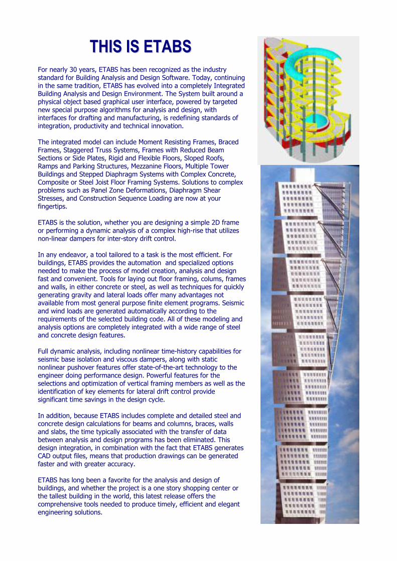
For nearly 30 years, ETABS has been recognized as the industry standard for Building Analysis and Design Software. Today, continuing in the same tradition, ETABS has evolved into a completely Integrated Building Analysis and Design Environment. The System built around a physical object based graphical user interface, powered by targeted new special purpose algorithms for analysis and design, with interfaces for drafting and manufacturing, is redefining standards of integration, productivity and technical innovation. The integrated model can include Moment Resisting Frames, Braced Frames, Staggered Truss Systems, Frames with Reduced Beam Sections or Side Plates, Rigid and Flexible Floors, Sloped Roofs, Ramps and Parking Structures, Mezzanine Floors, Multiple Tower Buildings and Stepped Diaphragm Systems with Complex Concrete, Composite or Steel Joist Floor Framing Systems. Solutions to complex problems such as Panel Zone Deformations, Diaphragm Shear Stresses, and Construction Sequence Loading are now at your fingertips. ETABS is the solution, whether you are designing a simple 2D frame or performing a dynamic analysis of a complex high-rise that utilizes non-linear dampers for inter-story drift control. In any endeavor, a tool tailored to a task is the most efficient. For buildings, ETABS provides the automation and specialized options needed to make the process of model creation, analysis and design fast and convenient. Tools for laying out floor framing, colums, frames and walls, in either concrete or steel, as well as techniques for quickly generating gravity and lateral loads offer many advantages not available from most general purpose finite element programs. Seismic and wind loads are generated automatically according to the requirements of the selected building code. All of these modeling and analysis options are completely integrated with a wide range of steel and concrete design features. Full dynamic analysis, including nonlinear time-history capabilities for seismic base isolation and viscous dampers, along with static nonlinear pushover features offer state-of-the-art technology to the engineer doing performance design. Powerful features for the selections and optimization of vertical framing members as well as the identification of key elements for lateral drift control provide significant time savings in the design cycle. In addition, because ETABS includes complete and detailed steel and concrete design calculations for beams and columns, braces, walls and slabs, the time typically associated with the transfer of data between analysis and design programs has been eliminated. This design integration, in combination with the fact that ETABS generates CAD output files, means that production drawings can be generated faster and with greater accuracy. ETABS has long been a favorite for the analysis and design of buildings, and whether the project is a one story shopping center or the tallest building in the world, this latest release offers the comprehensive tools needed to produce timely, efficient and elegant engineering solutions.
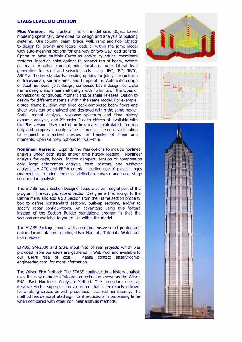
ETABS LEVEL DEFINITION Plus Version: No practical limit on model size. Object based modeling specifically developed for design and analysis of building systems. Use column, beam, brace, wall, ramp and floor objects to design for gravity and lateral loads all within the same model with auto-meshing options for one-way or two-way load transfer. Option to have multiple Cartesian and/or cylindrical coordinate systems. Insertion point options to connect top of beam, bottom of beam or other cardinal point locations. Auto lateral load generation for wind and seismic loads using UBC, IBC, NBCC, ASCE and other standards. Loading options for joint, line (uniform or trapezoidal), surface area, and temperature. Automatic design of steel members, joist design, composite beam design, concrete frame design, and shear wall design with no limits on the types of connections: continuous, moment and/or shear releases. Option to design for different materials within the same model. For example, a steel frame building with filled deck composite beam floors and shear walls can be analyzed and designed within the same model. Static, modal analysis, response spectrum and time history dynamic analysis, and 2nd order P-delta effects all available with the Plus version. User control on how mass is calculated. Tension only and compression only frame elements. Line constraint option to connect mismatched meshes for transfer of shear and moments. Open GL view options for walk-thru. Nonlinear Version: Expands the Plus options to include nonlinear analysis under both static and/or time history loading. Nonlinear analysis for gaps, hooks, friction dampers, tension or compression only, large deformation analysis, base isolators, and pushover analysis per ATC and FEMA criteria including use of plastic hinges (moment vs. rotation, force vs. deflection curves), and basic stage construction analysis.
The ETABS has a Section Designer feature as an integral part of the program. The way you access Section Designer is that you go to the Define menu and add a SD Section from the Frame section property box to define nonstandard sections, built-up sections, and/or to specify rebar configurations. An advantage using this feature instead of the Section Builder standalone program is that the sections are available to you to use within the model. The ETABS Package comes with a comprehensive set of printed and online documentation including: User Manuals, Tutorials, Watch and Learn Videos. ETABS, SAP2000 and SAFE input files of real projects which was provided from our users are gathered in Web-Pool and available to our users free of cost. Please contact [email protected] for more information. The Wilson FNA Method: The ETABS nonlinear time history analysis uses the new numerical Integration technique known as the Wilson FNA (Fast Nonlinear Analysis) Method. The procedure uses an iterative vector superposition algorithm that is extremely efficient for analzing structures with predefined, localized nonlinearity. The method has demonstrated significant reductions in processing times when compared with other nonlinear analysis methods.
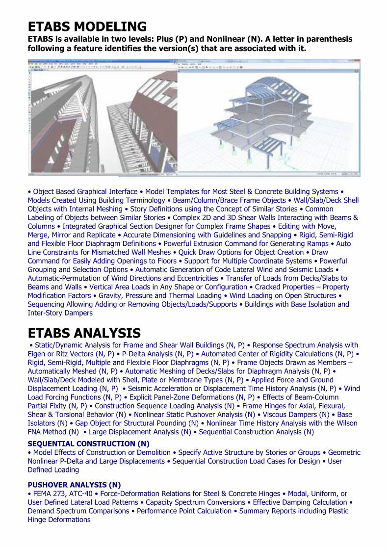
ETABS MODELING ETABS is available in two levels: Plus (P) and Nonlinear (N). A letter in parenthesis following a feature identifies the version(s) that are associated with it.
• Object Based Graphical Interface • Model Templates for Most Steel & Concrete Building Systems • Models Created Using Building Terminology • Beam/Column/Brace Frame Objects • Wall/Slab/Deck Shell Objects with Internal Meshing • Story Definitions using the Concept of Similar Stories • Common Labeling of Objects between Similar Stories • Complex 2D and 3D Shear Walls Interacting with Beams & Columns • Integrated Graphical Section Designer for Complex Frame Shapes • Editing with Move, Merge, Mirror and Replicate • Accurate Dimensioning with Guidelines and Snapping • Rigid, Semi-Rigid and Flexible Floor Diaphragm Definitions • Powerful Extrusion Command for Generating Ramps • Auto Line Constraints for Mismatched Wall Meshes • Quick Draw Options for Object Creation • Draw Command for Easily Adding Openings to Floors • Support for Multiple Coordinate Systems • Powerful Grouping and Selection Options • Automatic Generation of Code Lateral Wind and Seismic Loads • Automatic-Permutation of Wind Directions and Eccentricities • Transfer of Loads from Decks/Slabs to Beams and Walls • Vertical Area Loads in Any Shape or Configuration • Cracked Properties – Property Modification Factors • Gravity, Pressure and Thermal Loading • Wind Loading on Open Structures • Sequencing Allowing Adding or Removing Objects/Loads/Supports • Buildings with Base Isolation and Inter-Story Dampers
ETABS ANALYSIS • Static/Dynamic Analysis for Frame and Shear Wall Buildings (N, P) • Response Spectrum Analysis with Eigen or Ritz Vectors (N, P) • P-Delta Analysis (N, P) • Automated Center of Rigidity Calculations (N, P) • Rigid, Semi-Rigid, Multiple and Flexible Floor Diaphragms (N, P) • Frame Objects Drawn as Members – Automatically Meshed (N, P) • Automatic Meshing of Decks/Slabs for Diaphragm Analysis (N, P) • Wall/Slab/Deck Modeled with Shell, Plate or Membrane Types (N, P) • Applied Force and Ground Displacement Loading (N, P) • Seismic Acceleration or Displacement Time History Analysis (N, P) • Wind Load Forcing Functions (N, P) • Explicit Panel-Zone Deformations (N, P) • Effects of Beam-Column Partial Fixity (N, P) • Construction Sequence Loading Analysis (N) • Frame Hinges for Axial, Flexural, Shear & Torsional Behavior (N) • Nonlinear Static Pushover Analysis (N) • Viscous Dampers (N) • Base Isolators (N) • Gap Object for Structural Pounding (N) • Nonlinear Time History Analysis with the Wilson FNA Method (N) • Large Displacement Analysis (N) • Sequential Construction Analysis (N)
SEQUENTIAL CONSTRUCTION (N) • Model Effects of Construction or Demolition • Specify Active Structure by Stories or Groups • Geometric Nonlinear P-Delta and Large Displacements • Sequential Construction Load Cases for Design • User Defined Loading
PUSHOVER ANALYSIS (N) • FEMA 273, ATC-40 • Force-Deformation Relations for Steel & Concrete Hinges • Modal, Uniform, or User Defined Lateral Load Patterns • Capacity Spectrum Conversions • Effective Damping Calculation • Demand Spectrum Comparisons • Performance Point Calculation • Summary Reports including Plastic Hinge Deformations
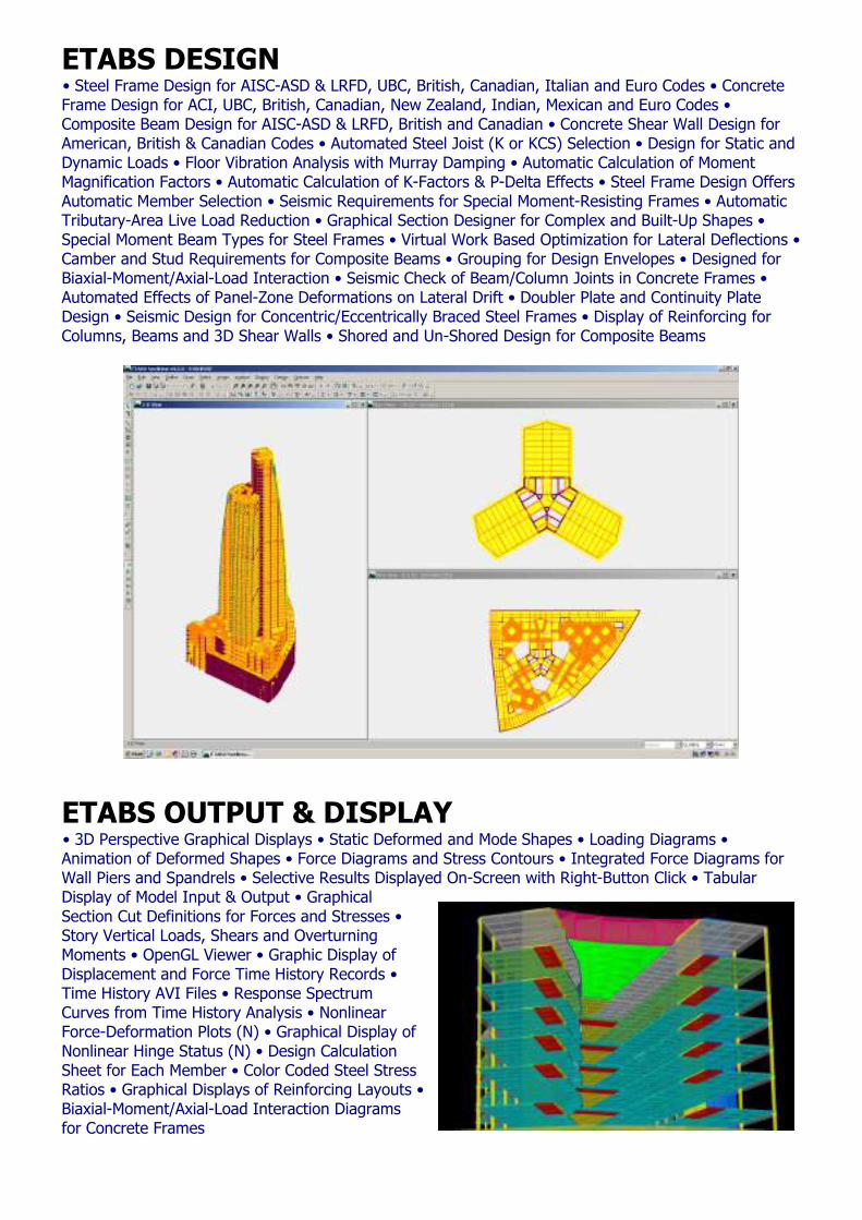
ETABS DESIGN • Steel Frame Design for AISC-ASD & LRFD, UBC, British, Canadian, Italian and Euro Codes • Concrete Frame Design for ACI, UBC, British, Canadian, New Zealand, Indian, Mexican and Euro Codes • Composite Beam Design for AISC-ASD & LRFD, British and Canadian • Concrete Shear Wall Design for American, British & Canadian Codes • Automated Steel Joist (K or KCS) Selection • Design for Static and Dynamic Loads • Floor Vibration Analysis with Murray Damping • Automatic Calculation of Moment Magnification Factors • Automatic Calculation of K-Factors & P-Delta Effects • Steel Frame Design Offers Automatic Member Selection • Seismic Requirements for Special Moment-Resisting Frames • Automatic Tributary-Area Live Load Reduction • Graphical Section Designer for Complex and Built-Up Shapes • Special Moment Beam Types for Steel Frames • Virtual Work Based Optimization for Lateral Deflections • Camber and Stud Requirements for Composite Beams • Grouping for Design Envelopes • Designed for Biaxial-Moment/Axial-Load Interaction • Seismic Check of Beam/Column Joints in Concrete Frames • Automated Effects of Panel-Zone Deformations on Lateral Drift • Doubler Plate and Continuity Plate Design • Seismic Design for Concentric/Eccentrically Braced Steel Frames • Display of Reinforcing for Columns, Beams and 3D Shear Walls • Shored and Un-Shored Design for Composite Beams
ETABS OUTPUT & DISPLAY • 3D Perspective Graphical Displays • Static Deformed and Mode Shapes • Loading Diagrams • Animation of Deformed Shapes • Force Diagrams and Stress Contours • Integrated Force Diagrams for Wall Piers and Spandrels • Selective Results Displayed On-Screen with Right-Button Click • Tabular Display of Model Input & Output • Graphical Section Cut Definitions for Forces and Stresses • Story Vertical Loads, Shears and Overturning Moments • OpenGL Viewer • Graphic Display of Displacement and Force Time History Records • Time History AVI Files • Response Spectrum Curves from Time History Analysis • Nonlinear Force-Deformation Plots (N) • Graphical Display of Nonlinear Hinge Status (N) • Design Calculation Sheet for Each Member • Color Coded Steel Stress Ratios • Graphical Displays of Reinforcing Layouts • Biaxial-Moment/Axial-Load Interaction Diagrams for Concrete Frames
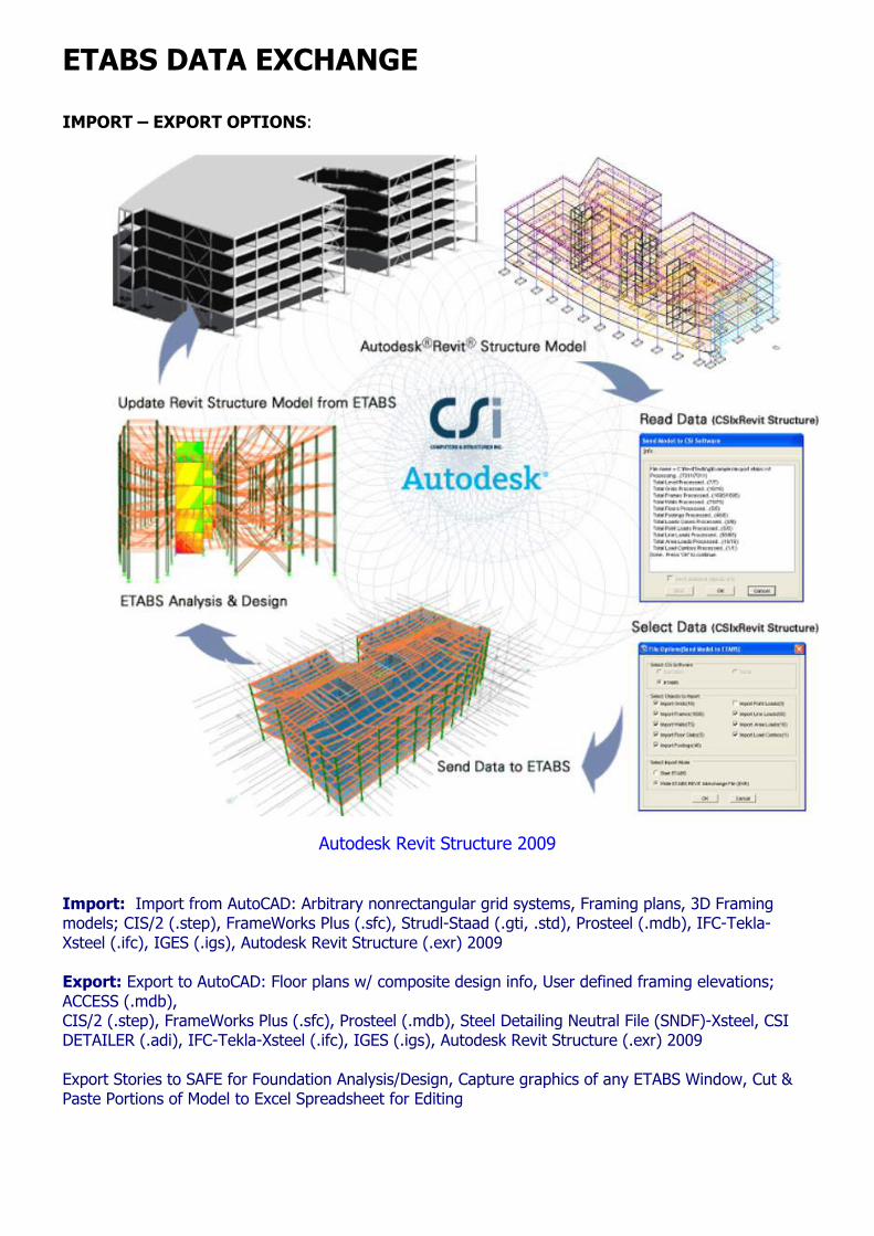
ETABS DATA EXCHANGE
IMPORT – EXPORT OPTIONS:
Autodesk Revit Structure 2009 Import: Import from AutoCAD: Arbitrary nonrectangular grid systems, Framing plans, 3D Framing models; CIS/2 (.step), FrameWorks Plus (.sfc), Strudl-Staad (.gti, .std), Prosteel (.mdb), IFC-Tekla-Xsteel (.ifc), IGES (.igs), Autodesk Revit Structure (.exr) 2009 Export: Export to AutoCAD: Floor plans w/ composite design info, User defined framing elevations; ACCESS (.mdb), CIS/2 (.step), FrameWorks Plus (.sfc), Prosteel (.mdb), Steel Detailing Neutral File (SNDF)-Xsteel, CSI DETAILER (.adi), IFC-Tekla-Xsteel (.ifc), IGES (.igs), Autodesk Revit Structure (.exr) 2009 Export Stories to SAFE for Foundation Analysis/Design, Capture graphics of any ETABS Window, Cut & Paste Portions of Model to Excel Spreadsheet for Editing
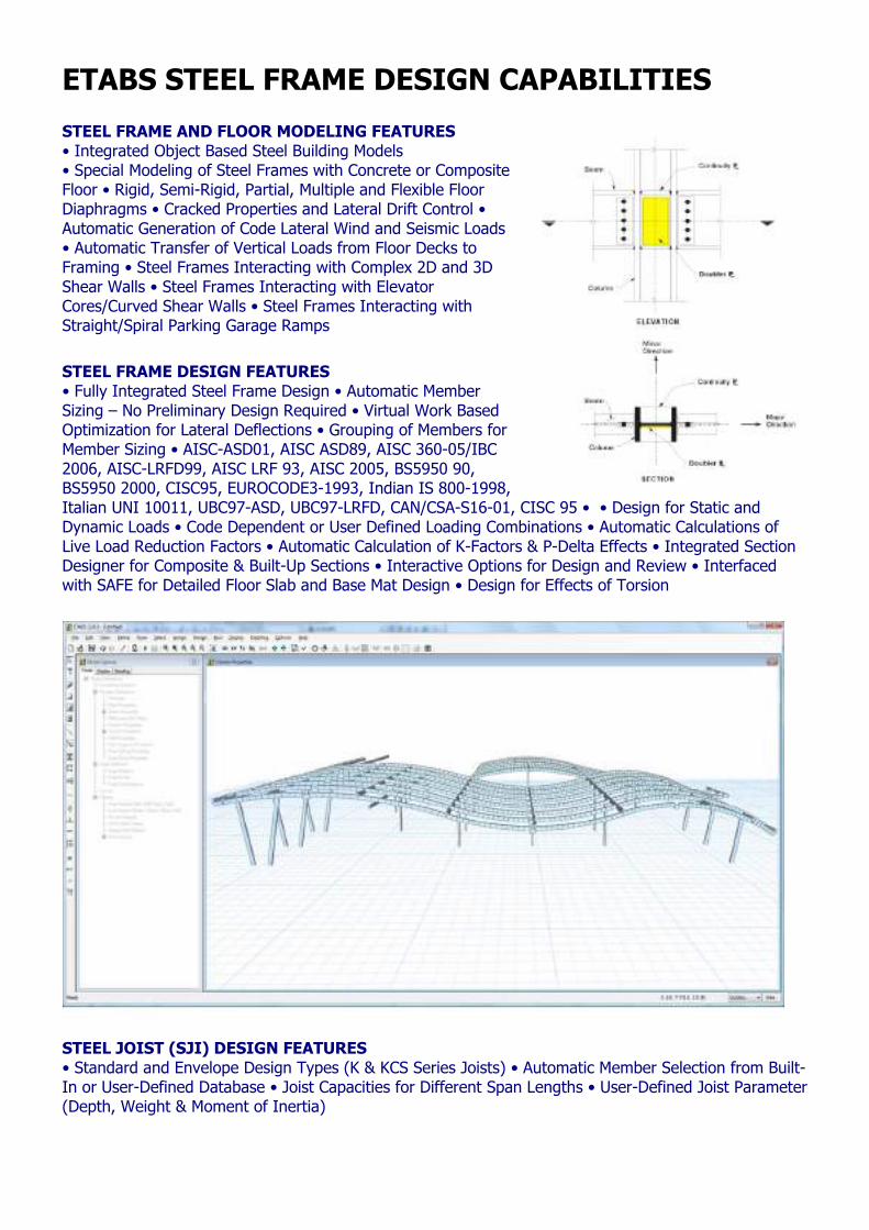
ETABS STEEL FRAME DESIGN CAPABILITIES
STEEL FRAME AND FLOOR MODELING FEATURES • Integrated Object Based Steel Building Models • Special Modeling of Steel Frames with Concrete or Composite Floor • Rigid, Semi-Rigid, Partial, Multiple and Flexible Floor Diaphragms • Cracked Properties and Lateral Drift Control • Automatic Generation of Code Lateral Wind and Seismic Loads • Automatic Transfer of Vertical Loads from Floor Decks to Framing • Steel Frames Interacting with Complex 2D and 3D Shear Walls • Steel Frames Interacting with Elevator Cores/Curved Shear Walls • Steel Frames Interacting with Straight/Spiral Parking Garage Ramps
STEEL FRAME DESIGN FEATURES • Fully Integrated Steel Frame Design • Automatic Member Sizing – No Preliminary Design Required • Virtual Work Based Optimization for Lateral Deflections • Grouping of Members for Member Sizing • AISC-ASD01, AISC ASD89, AISC 360-05/IBC 2006, AISC-LRFD99, AISC LRF 93, AISC 2005, BS5950 90, BS5950 2000, CISC95, EUROCODE3-1993, Indian IS 800-1998, Italian UNI 10011, UBC97-ASD, UBC97-LRFD, CAN/CSA-S16-01, CISC 95 • • Design for Static and Dynamic Loads • Code Dependent or User Defined Loading Combinations • Automatic Calculations of Live Load Reduction Factors • Automatic Calculation of K-Factors & P-Delta Effects • Integrated Section Designer for Composite & Built-Up Sections • Interactive Options for Design and Review • Interfaced with SAFE for Detailed Floor Slab and Base Mat Design • Design for Effects of Torsion
STEEL JOIST (SJI) DESIGN FEATURES • Standard and Envelope Design Types (K & KCS Series Joists) • Automatic Member Selection from Built-In or User-Defined Database • Joist Capacities for Different Span Lengths • User-Defined Joist Parameter (Depth, Weight & Moment of Inertia)
STEEL SEISMIC FRAME DESIGN FEATURES • Response Spectrum and Time History Based Structural Dynamics • Seismic Requirements for Special Moment-Resisting Frames • Seismic Requirements for Concentric/Eccentrically Braced Frames • Check of Panel-Zones for Doubler and Continuity Plates • Design of Intermediate/Special Moment-Resisting Frames • Interactive Evaluation of Floor Diaphragm Shears Using Section Cuts • Diaphragm Flexibility Effects to Obtain Chord & Collector Forces • Effects of Accidental Torsion with Centers of Rigidity
STEEL FRAME DESIGN OUTPUT FEATURES • Controlling Steel Member Sizes • Color Coded Controlling Steel Stress Ratios • Doubler Plate And Continuity Plate Design • Connection Design Forces • Design Data in Database Format
STEEL DETAILING FEATURES • TEKLA • IFC • CIS2 • Steel Detailing Neutral File • ProSteel 3D • Revit Structure • SAFE
POWER FEATURES FOR STEEL STRUCTURES • Effects of Construction Sequence Loading (N) • Automated Effects of Panel-Zone Deformations on Lateral Drift • Meshing Techniques for Interacting Shear Walls and Floors • Models Using Line Constraints • Eccentricities Due to Changes in Member Dimensions • Analytical Effects of Member Centerline Offsets In 3D • Effects of Beam-Column Partial Fixity • Three-Dimensional Pushover Analysis (N) • Buildings with Base Isolation and Inter-Story Dampers (N) • Element-Based P-Delta Effects for Local Buckling Instabilities (N) • Data Exchange with Detailing Packages
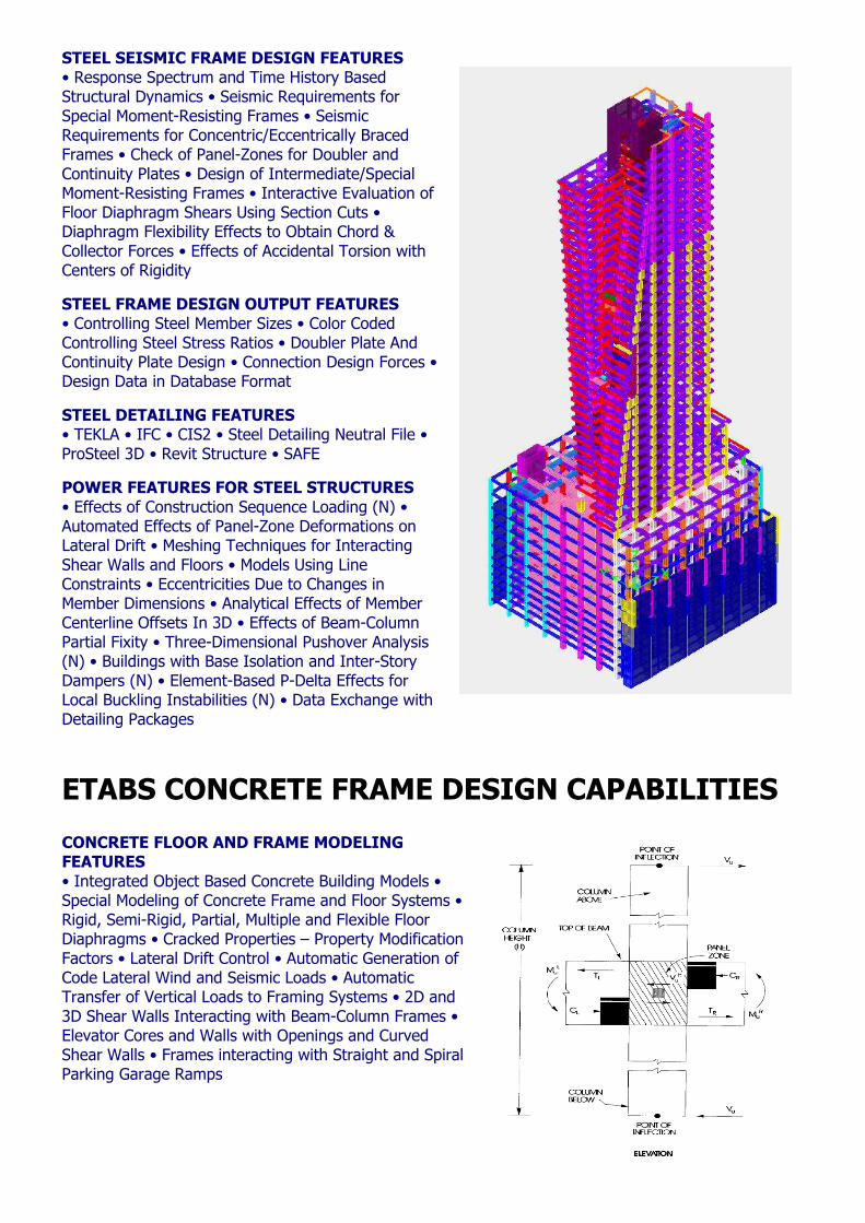
ETABS CONCRETE FRAME DESIGN CAPABILITIES
CONCRETE FLOOR AND FRAME MODELING FEATURES • Integrated Object Based Concrete Building Models • Special Modeling of Concrete Frame and Floor Systems • Rigid, Semi-Rigid, Partial, Multiple and Flexible Floor Diaphragms • Cracked Properties – Property Modification Factors • Lateral Drift Control • Automatic Generation of Code Lateral Wind and Seismic Loads • Automatic Transfer of Vertical Loads to Framing Systems • 2D and 3D Shear Walls Interacting with Beam-Column Frames • Elevator Cores and Walls with Openings and Curved Shear Walls • Frames interacting with Straight and Spiral Parking Garage Ramps
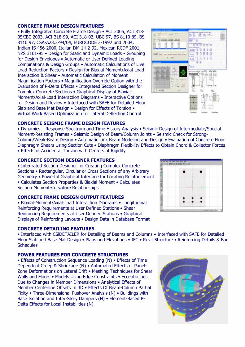
CONCRETE FRAME DESIGN FEATURES • Fully Integrated Concrete Frame Design • ACI 2005, ACI 318-05/IBC 2003, ACI 318-99, ACI 318-02, UBC 97, BS 8110 89, BS 8110 97, CSA-A23.3-94/04, EUROCODE 2-1992 und 2004, Indian IS 456-2000, Italian DM 14-2-92, Mexican RCDF 2001, NZS 3101-95 • Design for Static and Dynamic Loads • Grouping for Design Envelopes • Automatic or User Defined Loading Combinations & Design Groups • Automatic Calculations of Live Load Reduction Factors • Design for Biaxial-Moment/Axial-Load Interaction & Shear • Automatic Calculation of Moment Magnification Factors • Magnification Override Option with the Evaluation of P-Delta Effects • Integrated Section Designer for Complex Concrete Sections • Graphical Display of Biaxial-Moment/Axial-Load Interaction Diagrams • Interactive Options for Design and Review • Interfaced with SAFE for Detailed Floor Slab and Base Mat Design • Design for Effects of Torsion • Virtual Work Based Optimization for Lateral Deflection Control
CONCRETE SEISMIC FRAME DESIGN FEATURES • Dynamics – Response Spectrum and Time History Analysis • Seismic Design of Intermediate/Special Moment-Resisting Frames • Seismic Design of Beam/Column Joints • Seismic Check for Strong-Column/Weak-Beam Design • Automatic Link Beam Modeling and Design • Evaluation of Concrete Floor Diaphragm Shears Using Section Cuts • Diaphragm Flexibility Effects to Obtain Chord & Collector Forces • Effects of Accidental Torsion with Centers of Rigidity
CONCRETE SECTION DESIGNER FEATURES • Integrated Section Designer for Creating Complex Concrete Sections • Rectangular, Circular or Cross Sections of any Arbitrary Geometry • Powerful Graphical Interface for Locating Reinforcement • Calculates Section Properties & Biaxial Moment • Calculates Section Moment-Curvature Relationships
CONCRETE FRAME DESIGN OUTPUT FEATURES • Biaxial-Moment/Axial-Load Interaction Diagrams • Longitudinal Reinforcing Requirements at User Defined Stations • Shear Reinforcing Requirements at User Defined Stations • Graphical Displays of Reinforcing Layouts • Design Data in Database Format
CONCRETE DETAILING FEATURES • Interfaced with CSiDETAILER for Detailing of Beams and Columns • Interfaced with SAFE for Detailed Floor Slab and Base Mat Design • Plans and Elevations • IFC • Revit Structure • Reinforcing Details & Bar Schedules
POWER FEATURES FOR CONCRETE STRUCTURES • Effects of Construction Sequence Loading (N) • Effects of Time Dependent Creep & Shrinkage (N) • Automated Effects of Panel-Zone Deformations on Lateral Drift • Meshing Techniques for Shear Walls and Floors • Models Using Edge Constraints • Eccentricities Due to Changes in Member Dimensions • Analytical Effects of Member Centerline Offsets In 3D • Effects Of Beam-Column Partial Fixity • Three-Dimensional Pushover Analysis (N) • Buildings with Base Isolation and Inter-Story Dampers (N) • Element-Based P-Delta Effects for Local Instabilities (N)
ETABS CONCRETE SHEAR WALL DESIGN CAPABILITIES
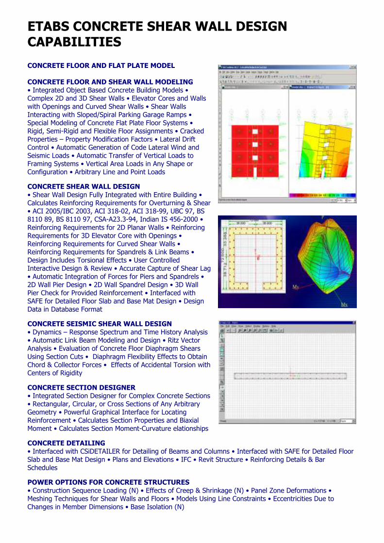
CONCRETE FLOOR AND FLAT PLATE MODEL CONCRETE FLOOR AND SHEAR WALL MODELING • Integrated Object Based Concrete Building Models • Complex 2D and 3D Shear Walls • Elevator Cores and Walls with Openings and Curved Shear Walls • Shear Walls Interacting with Sloped/Spiral Parking Garage Ramps • Special Modeling of Concrete Flat Plate Floor Systems • Rigid, Semi-Rigid and Flexible Floor Assignments • Cracked Properties – Property Modification Factors • Lateral Drift Control • Automatic Generation of Code Lateral Wind and Seismic Loads • Automatic Transfer of Vertical Loads to Framing Systems • Vertical Area Loads in Any Shape or Configuration • Arbitrary Line and Point Loads
CONCRETE SHEAR WALL DESIGN • Shear Wall Design Fully Integrated with Entire Building • Calculates Reinforcing Requirements for Overturning & Shear • ACI 2005/IBC 2003, ACI 318-02, ACI 318-99, UBC 97, BS 8110 89, BS 8110 97, CSA-A23.3-94, Indian IS 456-2000 • Reinforcing Requirements for 2D Planar Walls • Reinforcing Requirements for 3D Elevator Core with Openings • Reinforcing Requirements for Curved Shear Walls • Reinforcing Requirements for Spandrels & Link Beams • Design Includes Torsional Effects • User Controlled Interactive Design & Review • Accurate Capture of Shear Lag • Automatic Integration of Forces for Piers and Spandrels • 2D Wall Pier Design • 2D Wall Spandrel Design • 3D Wall Pier Check for Provided Reinforcement • Interfaced with SAFE for Detailed Floor Slab and Base Mat Design • Design Data in Database Format
CONCRETE SEISMIC SHEAR WALL DESIGN • Dynamics – Response Spectrum and Time History Analysis • Automatic Link Beam Modeling and Design • Ritz Vector Analysis • Evaluation of Concrete Floor Diaphragm Shears Using Section Cuts • Diaphragm Flexibility Effects to Obtain Chord & Collector Forces • Effects of Accidental Torsion with Centers of Rigidity
CONCRETE SECTION DESIGNER • Integrated Section Designer for Complex Concrete Sections • Rectangular, Circular, or Cross Sections of Any Arbitrary Geometry • Powerful Graphical Interface for Locating Reinforcement • Calculates Section Properties and Biaxial Moment • Calculates Section Moment-Curvature elationships
CONCRETE DETAILING • Interfaced with CSiDETAILER for Detailing of Beams and Columns • Interfaced with SAFE for Detailed Floor Slab and Base Mat Design • Plans and Elevations • IFC • Revit Structure • Reinforcing Details & Bar Schedules
POWER OPTIONS FOR CONCRETE STRUCTURES • Construction Sequence Loading (N) • Effects of Creep & Shrinkage (N) • Panel Zone Deformations • Meshing Techniques for Shear Walls and Floors • Models Using Line Constraints • Eccentricities Due to Changes in Member Dimensions • Base Isolation (N)
ETABS — PARKING STRUCTURES
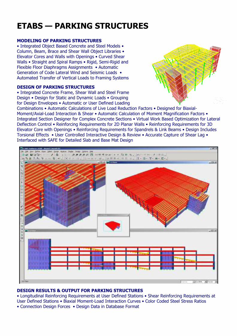
MODELING OF PARKING STRUCTURES • Integrated Object Based Concrete and Steel Models • Column, Beam, Brace and Shear Wall Object Libraries • Elevator Cores and Walls with Openings • Curved Shear Walls • Straight and Spiral Ramps • Rigid, Semi-Rigid and Flexible Floor Diaphragms Assignments • Automatic Generation of Code Lateral Wind and Seismic Loads • Automated Transfer of Vertical Loads to Framing Systems
DESIGN OF PARKING STRUCTURES • Integrated Concrete Frame, Shear Wall and Steel Frame Design • Design for Static and Dynamic Loads • Grouping for Design Envelopes • Automatic or User Defined Loading Combinations • Automatic Calculations of Live Load Reduction Factors • Designed for Biaxial-Moment/Axial-Load Interaction & Shear • Automatic Calculation of Moment Magnification Factors • Integrated Section Designer for Complex Concrete Sections • Virtual Work Based Optimization for Lateral Deflection Control • Reinforcing Requirements for 2D Planar Walls • Reinforcing Requirements for 3D Elevator Core with Openings • Reinforcing Requirements for Spandrels & Link Beams • Design Includes Torsional Effects • User Controlled Interactive Design & Review • Accurate Capture of Shear Lag • Interfaced with SAFE for Detailed Slab and Base Mat Design
DESIGN RESULTS & OUTPUT FOR PARKING STRUCTURES • Longitudinal Reinforcing Requirements at User Defined Stations • Shear Reinforcing Requirements at User Defined Stations • Biaxial Moment-Load Interaction Curves • Color Coded Steel Stress Ratios • Connection Design Forces • Design Data in Database Format
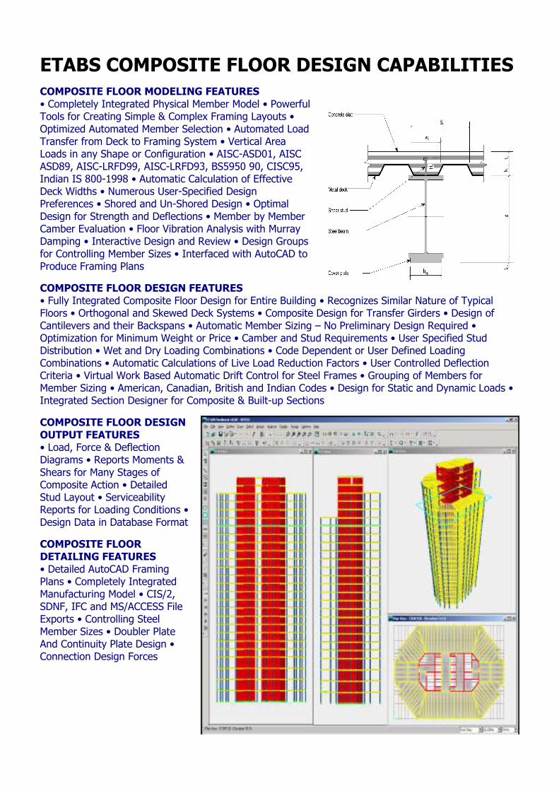
ETABS COMPOSITE FLOOR DESIGN CAPABILITIES COMPOSITE FLOOR MODELING FEATURES • Completely Integrated Physical Member Model • Powerful Tools for Creating Simple & Complex Framing Layouts • Optimized Automated Member Selection • Automated Load Transfer from Deck to Framing System • Vertical Area Loads in any Shape or Configuration • AISC-ASD01, AISC ASD89, AISC-LRFD99, AISC-LRFD93, BS5950 90, CISC95, Indian IS 800-1998 • Automatic Calculation of Effective Deck Widths • Numerous User-Specified Design Preferences • Shored and Un-Shored Design • Optimal Design for Strength and Deflections • Member by Member Camber Evaluation • Floor Vibration Analysis with Murray Damping • Interactive Design and Review • Design Groups for Controlling Member Sizes • Interfaced with AutoCAD to Produce Framing Plans
COMPOSITE FLOOR DESIGN FEATURES • Fully Integrated Composite Floor Design for Entire Building • Recognizes Similar Nature of Typical Floors • Orthogonal and Skewed Deck Systems • Composite Design for Transfer Girders • Design of Cantilevers and their Backspans • Automatic Member Sizing – No Preliminary Design Required • Optimization for Minimum Weight or Price • Camber and Stud Requirements • User Specified Stud Distribution • Wet and Dry Loading Combinations • Code Dependent or User Defined Loading Combinations • Automatic Calculations of Live Load Reduction Factors • User Controlled Deflection Criteria • Virtual Work Based Automatic Drift Control for Steel Frames • Grouping of Members for Member Sizing • American, Canadian, British and Indian Codes • Design for Static and Dynamic Loads • Integrated Section Designer for Composite & Built-up Sections
COMPOSITE FLOOR DESIGN OUTPUT FEATURES • Load, Force & Deflection Diagrams • Reports Moments & Shears for Many Stages of Composite Action • Detailed Stud Layout • Serviceability Reports for Loading Conditions • Design Data in Database Format
COMPOSITE FLOOR DETAILING FEATURES • Detailed AutoCAD Framing Plans • Completely Integrated Manufacturing Model • CIS/2, SDNF, IFC and MS/ACCESS File Exports • Controlling Steel Member Sizes • Doubler Plate And Continuity Plate Design • Connection Design Forces
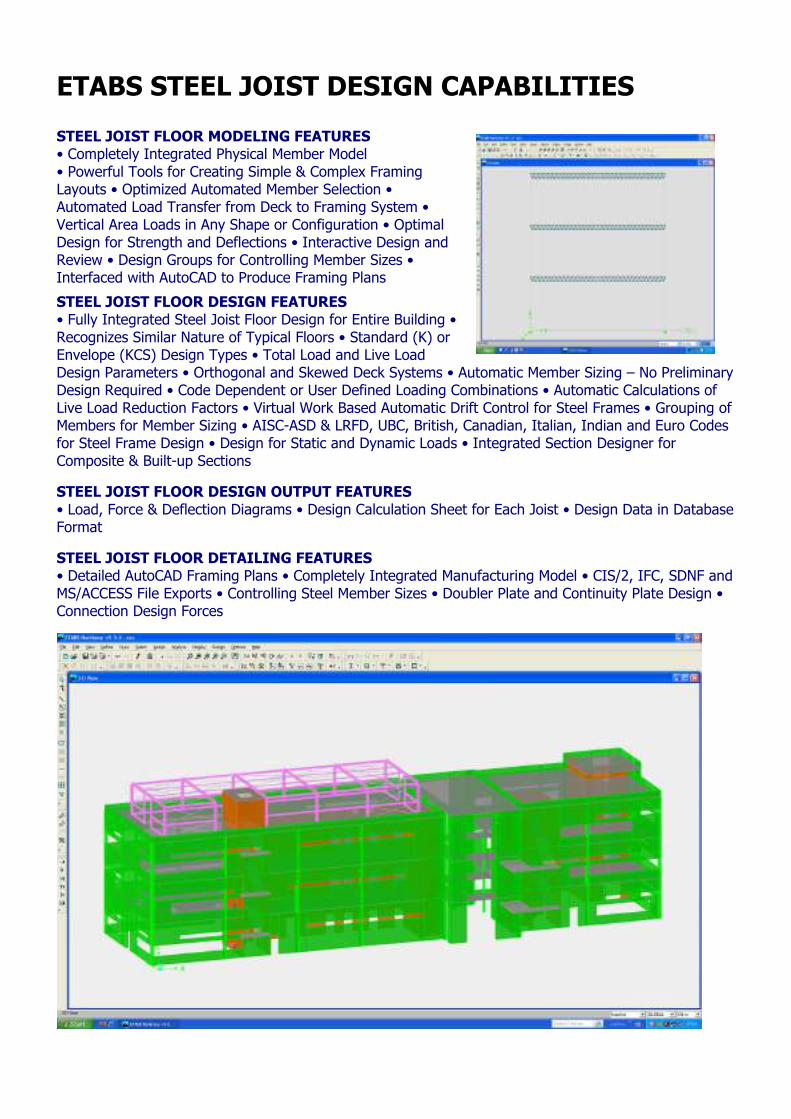
ETABS STEEL JOIST DESIGN CAPABILITIES STEEL JOIST FLOOR MODELING FEATURES • Completely Integrated Physical Member Model • Powerful Tools for Creating Simple & Complex Framing Layouts • Optimized Automated Member Selection • Automated Load Transfer from Deck to Framing System • Vertical Area Loads in Any Shape or Configuration • Optimal Design for Strength and Deflections • Interactive Design and Review • Design Groups for Controlling Member Sizes • Interfaced with AutoCAD to Produce Framing Plans
STEEL JOIST FLOOR DESIGN FEATURES • Fully Integrated Steel Joist Floor Design for Entire Building • Recognizes Similar Nature of Typical Floors • Standard (K) or Envelope (KCS) Design Types • Total Load and Live Load Design Parameters • Orthogonal and Skewed Deck Systems • Automatic Member Sizing – No Preliminary Design Required • Code Dependent or User Defined Loading Combinations • Automatic Calculations of Live Load Reduction Factors • Virtual Work Based Automatic Drift Control for Steel Frames • Grouping of Members for Member Sizing • AISC-ASD & LRFD, UBC, British, Canadian, Italian, Indian and Euro Codes for Steel Frame Design • Design for Static and Dynamic Loads • Integrated Section Designer for Composite & Built-up Sections
STEEL JOIST FLOOR DESIGN OUTPUT FEATURES • Load, Force & Deflection Diagrams • Design Calculation Sheet for Each Joist • Design Data in Database Format
STEEL JOIST FLOOR DETAILING FEATURES • Detailed AutoCAD Framing Plans • Completely Integrated Manufacturing Model • CIS/2, IFC, SDNF and MS/ACCESS File Exports • Controlling Steel Member Sizes • Doubler Plate and Continuity Plate Design • Connection Design Forces
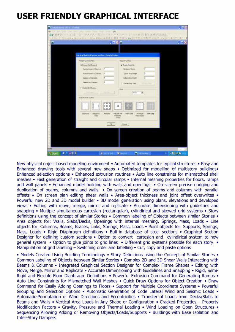
USER FRIENDLY GRAPHICAL INTERFACE
New physical object based modeling enviroment • Automated templates for typical structures • Easy and Enhanced drawing tools with several new snaps • Optimized for modelling of multistory buildings• Enhanced selection options • Enhanced extrusion routines • Auto line constraints for mismatched shell meshes • Fast generation of straight and circular ramps • Internal meshing properties for floors, ramps and wall panels • Enhanced model building with walls and openings • On screen precise nudging and duplication of beams, columns and walls • On screen creation of beams and columns with parallel offsets • On screen plan editing shear walls • Area-object thickness and joint offset overwrites • Powerful new 2D and 3D model builder • 3D model generation using plans, elevations and developed views • Editing with move, merge, mirror and replicate • Accurate dimensioning with guidelines and snapping • Multiple simultaneous cartesian (rectangular), cylindirical and skewed grid systems • Story definitions using the concept of similar Stories • Common labeling of Objects between similar Stories • Area objects for: Walls, Slabs/Decks, Openings with internal meshing, Springs, Mass, Loads • Line objects for: Columns, Beams, Braces, Links, Springs, Mass, Loads • Point objects for: Supports, Springs, Mass, Loads • Rigid Diaphragm definitions • Bult-in database of steel sections • Graphical Section Designer for defining custom sections • Option to convert cartesian and cylindirical system to new general system • Option to glue joints to grid lines • Different grid systems possible for each story • Manipulation of grid labelling – Switching order and labelling • Cut, copy and paste options
• Models Created Using Building Terminology • Story Definitions using the Concept of Similar Stories • Common Labeling of Objects between Similar Stories • Complex 2D and 3D Shear Walls Interacting with Beams & Columns • Integrated Graphical Section Designer for Complex Frame Shapes • Editing with Move, Merge, Mirror and Replicate • Accurate Dimensioning with Guidelines and Snapping • Rigid, Semi-Rigid and Flexible Floor Diaphragm Definitions • Powerful Extrusion Command for Generating Ramps • Auto Line Constraints for Mismatched Wall Meshes • Quick Draw Options for Object Creation • Draw Command for Easily Adding Openings to Floors • Support for Multiple Coordinate Systems • Powerful Grouping and Selection Options • Automatic Generation of Code Lateral Wind and Seismic Loads • Automatic-Permutation of Wind Directions and Eccentricities • Transfer of Loads from Decks/Slabs to Beams and Walls • Vertical Area Loads in Any Shape or Configuration • Cracked Properties – Property Modification Factors • Gravity, Pressure and Thermal Loading • Wind Loading on Open Structures • Sequencing Allowing Adding or Removing Objects/Loads/Supports • Buildings with Base Isolation and Inter-Story Dampers
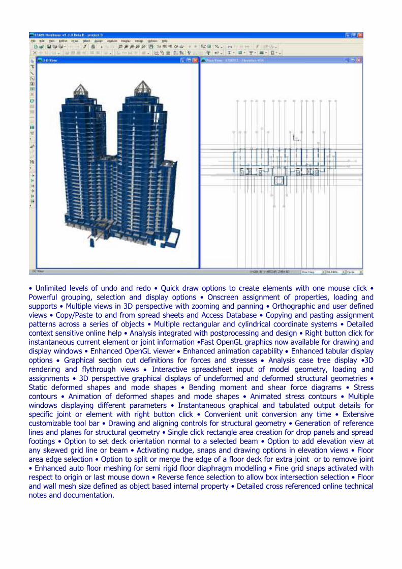
• Unlimited levels of undo and redo • Quick draw options to create elements with one mouse click • Powerful grouping, selection and display options • Onscreen assignment of properties, loading and supports • Multiple views in 3D perspective with zooming and panning • Orthographic and user defined views • Copy/Paste to and from spread sheets and Access Database • Copying and pasting assignment patterns across a series of objects • Multiple rectangular and cylindrical coordinate systems • Detailed context sensitive online help • Analysis integrated with postprocessing and design • Right button click for instantaneous current element or joint information •Fast OpenGL graphics now available for drawing and display windows • Enhanced OpenGL viewer • Enhanced animation capability • Enhanced tabular display options • Graphical section cut definitions for forces and stresses • Analysis case tree display •3D rendering and flythrough views • Interactive spreadsheet input of model geometry, loading and assignments • 3D perspective graphical displays of undeformed and deformed structural geometries • Static deformed shapes and mode shapes • Bending moment and shear force diagrams • Stress contours • Animation of deformed shapes and mode shapes • Animated stress contours • Multiple windows displaying different parameters • Instantaneous graphical and tabulated output details for specific joint or element with right button click • Convenient unit conversion any time • Extensive customizable tool bar • Drawing and aligning controls for structural geometry • Generation of reference lines and planes for structural geometry • Single click rectangle area creation for drop panels and spread footings • Option to set deck orientation normal to a selected beam • Option to add elevation view at any skewed grid line or beam • Activating nudge, snaps and drawing options in elevation views • Floor area edge selection • Option to split or merge the edge of a floor deck for extra joint or to remove joint • Enhanced auto floor meshing for semi rigid floor diaphragm modelling • Fine grid snaps activated with respect to origin or last mouse down • Reverse fence selection to allow box intersection selection • Floor and wall mesh size defined as object based internal property • Detailed cross referenced online technical notes and documentation.
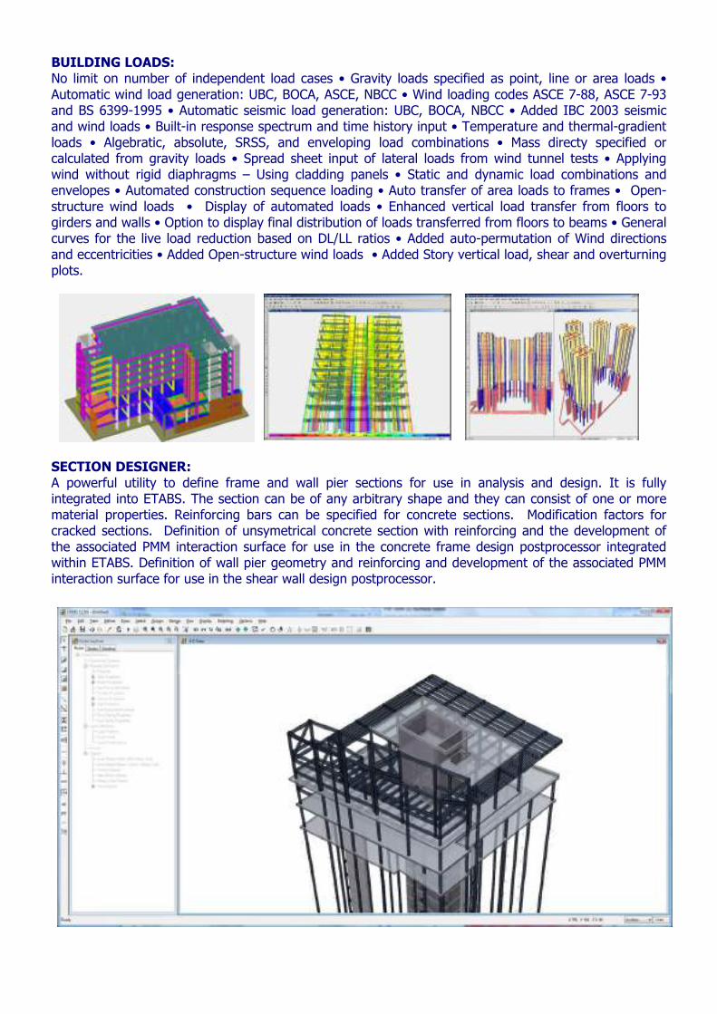
BUILDING LOADS: No limit on number of independent load cases • Gravity loads specified as point, line or area loads • Automatic wind load generation: UBC, BOCA, ASCE, NBCC • Wind loading codes ASCE 7-88, ASCE 7-93 and BS 6399-1995 • Automatic seismic load generation: UBC, BOCA, NBCC • Added IBC 2003 seismic and wind loads • Built-in response spectrum and time history input • Temperature and thermal-gradient loads • Algebratic, absolute, SRSS, and enveloping load combinations • Mass directy specified or calculated from gravity loads • Spread sheet input of lateral loads from wind tunnel tests • Applying wind without rigid diaphragms – Using cladding panels • Static and dynamic load combinations and envelopes • Automated construction sequence loading • Auto transfer of area loads to frames • Open-structure wind loads • Display of automated loads • Enhanced vertical load transfer from floors to girders and walls • Option to display final distribution of loads transferred from floors to beams • General curves for the live load reduction based on DL/LL ratios • Added auto-permutation of Wind directions and eccentricities • Added Open-structure wind loads • Added Story vertical load, shear and overturning plots.
SECTION DESIGNER: A powerful utility to define frame and wall pier sections for use in analysis and design. It is fully integrated into ETABS. The section can be of any arbitrary shape and they can consist of one or more material properties. Reinforcing bars can be specified for concrete sections. Modification factors for cracked sections. Definition of unsymetrical concrete section with reinforcing and the development of the associated PMM interaction surface for use in the concrete frame design postprocessor integrated within ETABS. Definition of wall pier geometry and reinforcing and development of the associated PMM interaction surface for use in the shear wall design postprocessor.
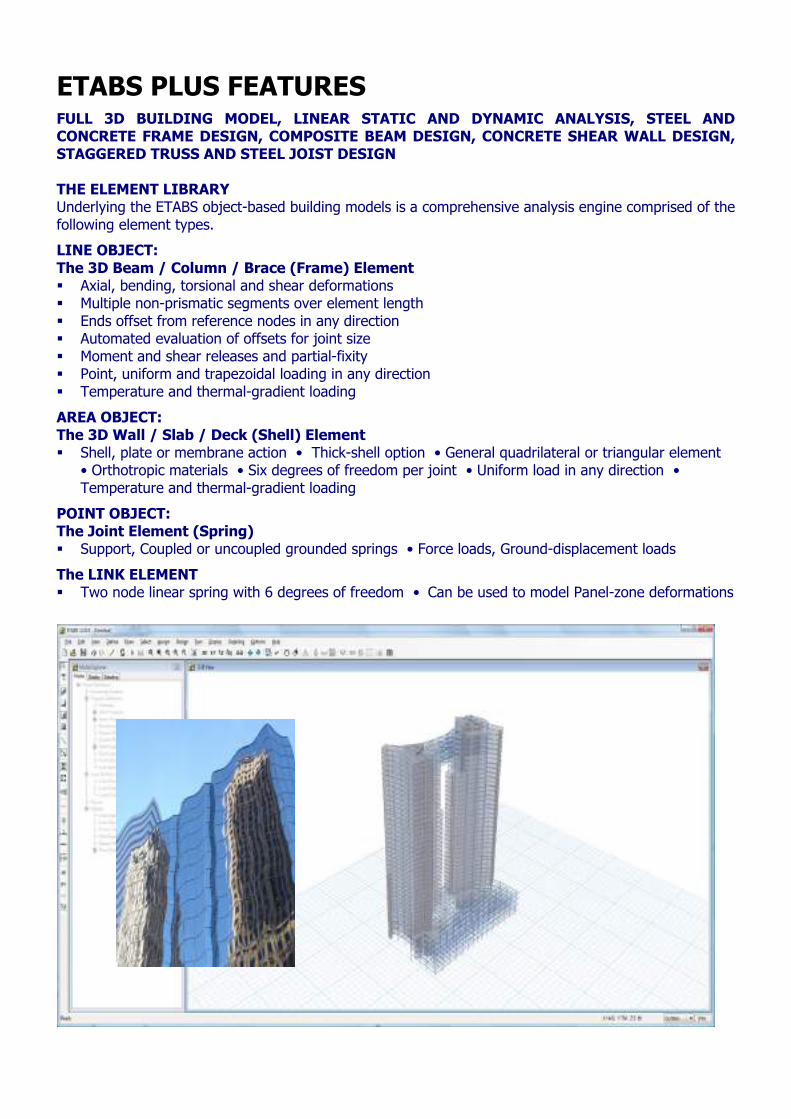
ETABS PLUS FEATURES
FULL 3D BUILDING MODEL, LINEAR STATIC AND DYNAMIC ANALYSIS, STEEL AND CONCRETE FRAME DESIGN, COMPOSITE BEAM DESIGN, CONCRETE SHEAR WALL DESIGN, STAGGERED TRUSS AND STEEL JOIST DESIGN THE ELEMENT LIBRARY Underlying the ETABS object-based building models is a comprehensive analysis engine comprised of the following element types.
LINE OBJECT: The 3D Beam / Column / Brace (Frame) Element Axial, bending, torsional and shear deformations Multiple non-prismatic segments over element length Ends offset from reference nodes in any direction Automated evaluation of offsets for joint size Moment and shear releases and partial-fixity Point, uniform and trapezoidal loading in any direction Temperature and thermal-gradient loading
AREA OBJECT: The 3D Wall / Slab / Deck (Shell) Element Shell, plate or membrane action • Thick-shell option • General quadrilateral or triangular element
• Orthotropic materials • Six degrees of freedom per joint • Uniform load in any direction • Temperature and thermal-gradient loading
POINT OBJECT: The Joint Element (Spring) Support, Coupled or uncoupled grounded springs • Force loads, Ground-displacement loads
The LINK ELEMENT Two node linear spring with 6 degrees of freedom • Can be used to model Panel-zone deformations
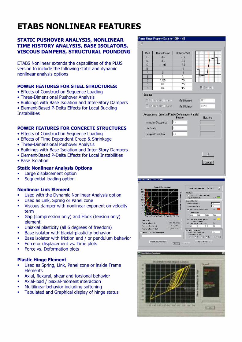
ETABS NONLINEAR FEATURES STATIC PUSHOVER ANALYSIS, NONLINEAR TIME HISTORY ANALYSIS, BASE ISOLATORS, VISCOUS DAMPERS, STRUCTURAL POUNDING ETABS Nonlinear extends the capabilities of the PLUS version to include the following static and dynamic nonlinear analysis options
POWER FEATURES FOR STEEL STRUCTURES: • Effects of Construction Sequence Loading • Three-Dimensional Pushover Analysis • Buildings with Base Isolation and Inter-Story Dampers • Element-Based P-Delta Effects for Local Buckling Instabilities
POWER FEATURES FOR CONCRETE STRUCTURES • Effects of Construction Sequence Loading • Effects of Time Dependent Creep & Shrinkage • Three-Dimensional Pushover Analysis • Buildings with Base Isolation and Inter-Story Dampers • Element-Based P-Delta Effects for Local Instabilities • Base Isolation
Static Nonlinear Analysis Options Large displacement option Sequential loading option
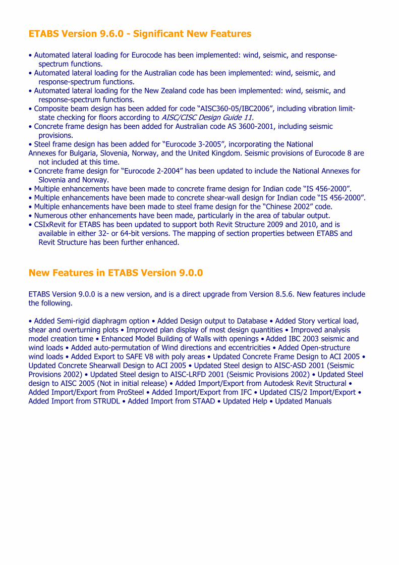
Nonlinear Link Element Used with the Dynamic Nonlinear Analysis option Used as Link, Spring or Panel zone Viscous damper with nonlinear exponent on velocity
term Gap (compression only) and Hook (tension only)
element Uniaxial plasticity (all 6 degrees of freedom) Base isolator with biaxial-plasticity behavior Base isolator with friction and / or pendulum behavior Force or displacement vs. Time plots Force vs. Deformation plots
Plastic Hinge Element Used as Spring, Link, Panel zone or inside Frame
Elements Axial, flexural, shear and torsional behavior Axial-load / biaxial-moment interaction Multilinear behavior including softening Tabulated and Graphical display of hinge status
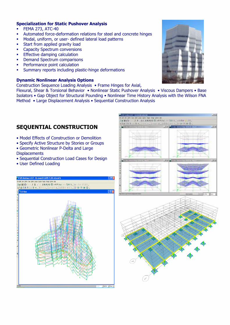
Specialization for Static Pushover Analysis FEMA 273, ATC-40 Automated force-deformation relations for steel and concrete hinges Modal, uniform, or user- defined lateral load patterns Start from applied gravity load Capacity Spectrum conversions Effective damping calculation Demand Spectrum comparisons Performance point calculation Summary reports including plastic-hinge deformations
Dynamic Nonlinear Analysis Options Construction Sequence Loading Analysis • Frame Hinges for Axial, Flexural, Shear & Torsional Behavior • Nonlinear Static Pushover Analysis • Viscous Dampers • Base Isolators • Gap Object for Structural Pounding • Nonlinear Time History Analysis with the Wilson FNA Method • Large Displacement Analysis • Sequential Construction Analysis
SEQUENTIAL CONSTRUCTION • Model Effects of Construction or Demolition • Specify Active Structure by Stories or Groups • Geometric Nonlinear P-Delta and Large Displacements • Sequential Construction Load Cases for Design • User Defined Loading
ETABS Version 9.6.0 - Significant New Features • Automated lateral loading for Eurocode has been implemented: wind, seismic, and response-
spectrum functions. • Automated lateral loading for the Australian code has been implemented: wind, seismic, and
response-spectrum functions. • Automated lateral loading for the New Zealand code has been implemented: wind, seismic, and
response-spectrum functions. • Composite beam design has been added for code “AISC360-05/IBC2006”, including vibration limit-
state checking for floors according to AISC/CISC Design Guide 11. • Concrete frame design has been added for Australian code AS 3600-2001, including seismic
provisions. • Steel frame design has been added for “Eurocode 3-2005”, incorporating the National Annexes for Bulgaria, Slovenia, Norway, and the United Kingdom. Seismic provisions of Eurocode 8 are
not included at this time. • Concrete frame design for “Eurocode 2-2004” has been updated to include the National Annexes for
Slovenia and Norway. • Multiple enhancements have been made to concrete frame design for Indian code “IS 456-2000”. • Multiple enhancements have been made to concrete shear-wall design for Indian code “IS 456-2000”. • Multiple enhancements have been made to steel frame design for the “Chinese 2002” code. • Numerous other enhancements have been made, particularly in the area of tabular output. • CSIxRevit for ETABS has been updated to support both Revit Structure 2009 and 2010, and is
available in either 32- or 64-bit versions. The mapping of section properties between ETABS and Revit Structure has been further enhanced.
New Features in ETABS Version 9.0.0 ETABS Version 9.0.0 is a new version, and is a direct upgrade from Version 8.5.6. New features include the following. • Added Semi-rigid diaphragm option • Added Design output to Database • Added Story vertical load, shear and overturning plots • Improved plan display of most design quantities • Improved analysis model creation time • Enhanced Model Building of Walls with openings • Added IBC 2003 seismic and wind loads • Added auto-permutation of Wind directions and eccentricities • Added Open-structure wind loads • Added Export to SAFE V8 with poly areas • Updated Concrete Frame Design to ACI 2005 • Updated Concrete Shearwall Design to ACI 2005 • Updated Steel design to AISC-ASD 2001 (Seismic Provisions 2002) • Updated Steel design to AISC-LRFD 2001 (Seismic Provisions 2002) • Updated Steel design to AISC 2005 (Not in initial release) • Added Import/Export from Autodesk Revit Structural • Added Import/Export from ProSteel • Added Import/Export from IFC • Updated CIS/2 Import/Export • Added Import from STRUDL • Added Import from STAAD • Updated Help • Updated Manuals
Distributor: COMPUTERS & ENGINEERING Engineering Software Consulting and Provision Center
Holzmühler Weg 87-89, D-35457 Lollar - Germany Tel: 0049 (0) 6406 73667 Fax: 0049 (0) 6406 4745
E-Mail: [email protected] http://www.comp-engineering.com
Download Trial versions: www.comp-engineering.com/download.htm