Embed Size (px)
Citation preview
In-line Pump
Etaline PumpDrive 2 /Etaline PumpDrive 2 Eco
Type Series Booklet

Legal information/Copyright
Type Series Booklet Etaline PumpDrive 2 / Etaline PumpDrive 2 Eco
All rights reserved. The contents provided herein must neither be distributed, copied, reproduced,edited or processed for any other purpose, nor otherwise transmitted, published or made available toa third party without the manufacturer's express written consent.
Subject to technical modification without prior notice.
© KSB Aktiengesellschaft, Frankenthal 27.10.2014
Contents
Heating / Air-conditioning / Ventilation ..........................................................................................................4
In-line Pump with Motor-mounted Variable Speed System ......................................................................................... 4
Etaline PumpDrive 2 / Etaline PumpDrive 2 Eco ...................................................................................................... 4
Main applications ................................................................................................................................................ 4
Fluids handled ...................................................................................................................................................... 4
Operating data .................................................................................................................................................... 4
Designation .......................................................................................................................................................... 4
Design details ....................................................................................................................................................... 4
Coating and preservation ................................................................................................................................... 5
Product benefits .................................................................................................................................................. 5
Certifications ........................................................................................................................................................ 5
Product information as per Regulation No. 547/2012 (for water pumps with a maximum shaft power of150 kW) implementing "Ecodesign" Directive 2009/125/EC ............................................................................. 5
Acceptance tests / warranty ................................................................................................................................ 5
Project planning information ............................................................................................................................. 6
Programme overview / selection tables ............................................................................................................. 9
Pressure and temperature limits ....................................................................................................................... 12
Materials ............................................................................................................................................................ 13
Technical data .................................................................................................................................................... 13
Selection charts ................................................................................................................................................. 16
Dimensions and connections ............................................................................................................................ 17
Flange design ..................................................................................................................................................... 22
Flange dimensions ............................................................................................................................................. 22
Typical installation positions ............................................................................................................................. 23
Accessories ......................................................................................................................................................... 25
Detailed designation (Etaline only) .................................................................................................................. 26
PumpMeter .............................................................................................................................................................. 28
General description ........................................................................................................................................... 28
Main applications .............................................................................................................................................. 28
Technical data .................................................................................................................................................... 28
Materials ............................................................................................................................................................ 28
Product benefits ................................................................................................................................................ 28
Functions ............................................................................................................................................................ 29
Design variants .................................................................................................................................................. 30
Electrical connections ........................................................................................................................................ 31
Dimensions ......................................................................................................................................................... 31
Contents
3
Heating / Air-conditioning / Ventilation
In-line Pump with Motor-mounted Variable SpeedSystem
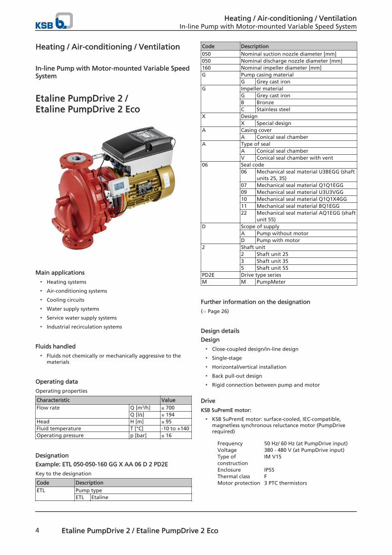
Etaline PumpDrive 2 /Etaline PumpDrive 2 Eco
Main applications
▪ Heating systems
▪ Air-conditioning systems
▪ Cooling circuits
▪ Water supply systems
▪ Service water supply systems
▪ Industrial recirculation systems
Fluids handled
▪ Fluids not chemically or mechanically aggressive to thematerials
Operating data
Operating properties
Characteristic ValueFlow rate Q [m3/h] ≤ 700
Q [l/s] ≤ 194Head H [m] ≤ 95Fluid temperature T [°C] -10 to +140Operating pressure p [bar] ≤ 16
Designation
Example: ETL 050-050-160 GG X AA 06 D 2 PD2E
Key to the designation
Code DescriptionETL Pump type
ETL Etaline
Code Description050 Nominal suction nozzle diameter [mm]050 Nominal discharge nozzle diameter [mm]160 Nominal impeller diameter [mm]G Pump casing material
G Grey cast ironG Impeller material
G Grey cast ironB BronzeC Stainless steel
X DesignX Special design
A Casing coverA Conical seal chamber
A Type of sealA Conical seal chamberV Conical seal chamber with vent
06 Seal code06 Mechanical seal material U3BEGG (shaft
units 25, 35)07 Mechanical seal material Q1Q1EGG09 Mechanical seal material U3U3VGG10 Mechanical seal material Q1Q1X4GG11 Mechanical seal material BQ1EGG22 Mechanical seal material AQ1EGG (shaft
unit 55)D Scope of supply
A Pump without motorD Pump with motor
2 Shaft unit2 Shaft unit 253 Shaft unit 355 Shaft unit 55
PD2E Drive type seriesM M PumpMeter
Further information on the designation
(⇨ Page 26)
Design details
Design
▪ Close-coupled design/in-line design
▪ Single-stage
▪ Horizontal/vertical installation
▪ Back pull-out design
▪ Rigid connection between pump and motor
Drive
KSB SuPremE motor:
▪ KSB SuPremE motor: surface-cooled, IEC-compatible,magnetless synchronous reluctance motor (PumpDriverequired)
Frequency 50 Hz/ 60 Hz (at PumpDrive input)Voltage 380 - 480 V (at PumpDrive input)Type ofconstruction
IM V15
Enclosure IP55Thermal class FMotor protection 3 PTC thermistors
Heating / Air-conditioning / VentilationIn-line Pump with Motor-mounted Variable Speed System
4 Etaline PumpDrive 2 / Etaline PumpDrive 2 Eco
Mode ofoperation
Continuous operation S1
Efficiency class IE4, as per IEC/CD 60034-30 Ed.2
The motors differ as follows:
▪ KSB SuPremE B1with terminal box for connection to wall- or cabinet-mounted PumpDrive 1 or PumpDrive 2 / PumpDrive R
▪ KSB SuPremE B2equipped for being fitted with a motor-mountedPumpDrive 2
Types of construction
Type of construction Shaftcentreline
height[mm]
Mountingarrangement
IM ...Flange type1) Foot
None with 71 - 225 B3FF with 71 - 225 V15
without 71 - 160 V1FT with - -
without up to 132 V18
Asynchronous motor:
▪ KSB/Siemens surface-cooled IEC frame three-phase currentsquirrel-cage motor
Winding Up to 2.2 kW: 220-240 V/ 380-420 VFrom 3 kW: 380-420 V/ 660-725 V
Type ofconstruction
Up to 4 kW: IM V1From 5.5 kW: IM V15
Enclosure IP55
Thermal class F
Motor protection: 3 PTC thermistors
Efficiency class: IE2 or IE3
Mode ofoperation
Continuous operation S1
PumpDrive:
Mains voltage 3 ~ 380 V AC -10 % to 480 V AC +10%
Mains frequency 50 - 60 Hz ± 2 %
Enclosure IP55
Shaft seal
▪ Standardised mechanical seal to EN 12756
Bearings
▪ Radial ball bearings in the motor housing
▪ Grease lubrication
Coating and preservation
▪ Coating and preservation to KSB standard
Product benefits
▪ Maximum energy efficiency through demand-drivenoperation in combination with KSB SuPremE IE4 motor
▪ PumpDrive perfectly matched to pump and motor bydefault factory parameter settings
▪ Space-saving owing to motor-mounted variable speedsystem up to 45 kW
▪ Pump operation made fully transparent with PumpMeter
Certifications
This product is subject to the provisions of the "Ecodesign"Directive 2009/125/EC and meets, as a minimum, the ecodesignrequirements established in 2013 for water pumps with amaximum shaft power of 150 kW as per Regulation (EU)No. 547/2012.
Product information as per Regulation No. 547/2012 (forwater pumps with a maximum shaft power of 150 kW)implementing "Ecodesign" Directive 2009/125/EC
▪ Minimum efficiency index: see data sheet
▪ The benchmark for the most efficient water pumps is MEI≥ 0.70.
▪ Year of construction: see data sheet
▪ Manufacturer’s name or trade mark, commercialregistration number and place of manufacture: see datasheet or order documentation
▪ Product’s type and size identificator: see data sheet
▪ Hydraulic pump efficiency (%) with trimmed impeller: seedata sheet
▪ Pump performance curves, including efficiencycharacteristics: see documented characteristic curve
▪ The efficiency of a pump with a trimmed impeller isusually lower than that of a pump with full impellerdiameter. Trimming of the impeller will adapt the pumpto a fixed duty point, leading to reduced energyconsumption. The minimum efficiency index (MEI) is basedon the full impeller diameter.
▪ Operation of this water pump with variable duty pointsmay be more efficient and economic when controlled, forexample, by the use of a variable speed drive that matchesthe pump duty to the system.
▪ Information relevant for disassembly, recycling or disposalat end of life: see installation/operating manual
▪ Information on benchmark efficiency or benchmarkefficiency graph for MEI = 0.7 (0.4) for the pump based onthe model shown in the Figure are available at: http://www.europump.org/efficiencycharts
Acceptance tests / warranty
The following acceptance tests may be performed at asurcharge:
▪ Materials testing
– Test report 2.2
▪ Final inspection
– Inspection certificate 3.1 to EN 10204
▪ Hydraulic test
– The duty point of each pump is guaranteed accordingto ISO 9906/2B or ISO 9906/3B.
– NPSH test
▪ Other inspections/tests on request
Warranties
1) Designations to EN 50347
Heating / Air-conditioning / VentilationIn-line Pump with Motor-mounted Variable Speed System
Etaline PumpDrive 2 / Etaline PumpDrive 2 Eco 5
▪ Warranties are given within the scope of the valid deliveryconditions.
Project planning information
Selecting power/connection cables
Unshielded cables can be used as power cables.
The power cables must be designed with a cross-sectionsuitable for the nominal mains current.
If a mains contactor is used in the power cable (before thefrequency inverter), this must be configured for an AC1 dutyrating; the rated current values of the frequency inverters usedare added and the result is increased by 15 %.
Power/connection cable properties
Size Power Cable gland for Nominalcurrent2)
, mains
Max
imu
m c
ore
cro
ss-s
ecti
on
Cab
le c
ross
-sec
tio
nK
SB m
oto
r ca
ble
Mai
ns
po
wer
cab
le
Sen
sor
cab
le
Mo
tor
cab
le
PTC
th
erm
isto
r[kW] [A] [mm²]
A
.. 000K37 .. 0,37 M25
M16
M25
M16 1,4 2,5 1,5.. 000K55 .. 0,55 2,0.. 000K75 .. 0,75 2,7..001K10.. 1,1 3,7
B .. 001K50 .. 1,5 M25 M16 M25 M16 5,2 2,5.. 002K20 .. 2,2 6,3.. 003K00 .. 3 8,4.. 004K00 .. 4 10,4
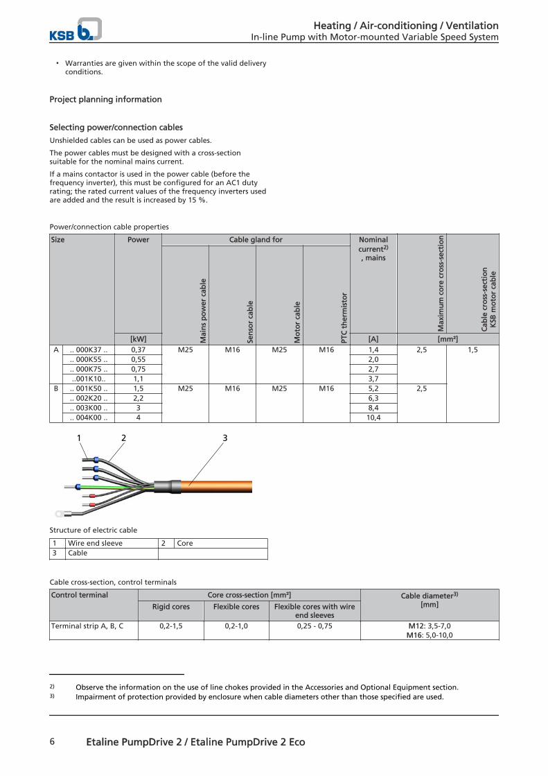
1 2 3
Structure of electric cable
1 Wire end sleeve 2 Core3 Cable
Cable cross-section, control terminals
Control terminal Core cross-section [mm²] Cable diameter3)
[mm]Rigid cores Flexible cores Flexible cores with wireend sleeves
Terminal strip A, B, C 0,2-1,5 0,2-1,0 0,25 - 0,75 M12: 3,5-7,0M16: 5,0-10,0
2) Observe the information on the use of line chokes provided in the Accessories and Optional Equipment section.3) Impairment of protection provided by enclosure when cable diameters other than those specified are used.
Heating / Air-conditioning / VentilationIn-line Pump with Motor-mounted Variable Speed System
6 Etaline PumpDrive 2 / Etaline PumpDrive 2 Eco
Length of motor connection cable
If the frequency inverter is not mounted on the motor to becontrolled, longer motor connection cables may be required.The stray capacitance of the connection cables may result inhigh-frequency discharge currents flowing to ground. The sumof the discharge currents and motor current may exceed theoutput-side rated current of the frequency inverter. This willactivate the frequency inverter's protection equipment and themotor will be stopped. The following motor connection cablesare recommended depending on the power range:
Length of motor connection cable
Power range [kW]
Maximum cablelength
[m]
Stray capacitance [nF]
≤ 7.5 (Class B) 5 ≤ 5
Output filter
If longer connection cables than those listed above arerequired or the connection cable's stray capacitance valueexceeds the above values, we recommend installing a suitableoutput filter between the frequency inverter and the motor tobe controlled. These filters reduce the voltage ramp-up time ofthe frequency inverter output voltages and limit their peaks.
Electrical protection device
Back-up fuses
Provide three fast-acting fuses in the mains power supply tothe frequency inverter. The fuse size must be suitable for thenominal mains current supplied to the frequency inverter.
Motor protection switch
Separate motor protection is not required because thefrequency inverter has its own safety devices (e.g. electronicovercurrent trip). Set any motor protection switches fitted to aminimum of 1.4 times the nominal (mains) current.
Residual current device
If fixed connections and appropriate supplementary earthingare used (cf. DIN VDE 0160), RCDs are not mandatory forfrequency inverters.
If residual current devices (RCDs) are used, three-phasefrequency inverters must in accordance with DIN VDE 0160 beconnected via universal AC/DC sensitive residual current devices(RCDs), as potential direct-current components may causestandard AC sensitive RCDs to either fail to respond or responderroneously.
Residual current device to be selected
Size Rated currentA and B 150 mA
If you are using a long shielded cable for the mains/motorconnection, the residual-current monitoring device may betriggered by the discharge current that flows to earth(triggered by the carrier frequency). Remedies: Replace theRCD (residual current device) or lower the response limit.
Information on electromagnetic compatibility
Electromagnetic interference from other electrical devices canaffect the frequency inverter. Interference can also begenerated by the frequency inverter itself, however.
Interference emitted by the frequency inverter is generallyconducted through the motor connection cables. Thefollowing measures are proposed for RFI suppression:
▪ Shielded motor connection cables for line lengths > 70 cm(especially recommended for frequency inverters with lowpower ratings)
▪ Made from a single piece of formed metal cable ductingwith a minimum coverage of 80 % (if shielded connectioncables cannot be used)
Use different earth bus bars for the control cable and mainspower/motor connection cables.
The shield on the power cable/connection cable must consist ofa single piece and be earthed at both ends either just on theappropriate earth terminal or on the earth bus bar (do notconnect it to the earth bus bar in the control cabinet).
The shielded cable ensures that the high-frequency current,which normally flows as a discharge current from the motorhousing to earth or between the individual conductors, flowsthrough the shielding.
The shield for the control cable (connection on the frequencyinverter side only) also serves as protection against radiatedemission.
If using shielded cables, use a wide contact face for thedifferent earth connections to ensure greater interferenceimmunity.
In applications with long shielded motor cables, provideadditional reactive resistors or output filters to compensate thecapacitive stray current to earth and reduce the rate of voltagerise on the motor. These measures help reduce radiointerference further. Using just ferrite rings or reactive resistorsdoes not ensure compliance with the limit values defined inthe EMC directive.
NOTE! If you are using shielded cables that are longer than10 m, check the stray capacitance to ensure that the diffusionbetween the phases or to earth is not excessive, which couldcause the frequency inverter to stop.
Route control cable and mains power/motor connection cablesin separate cable ducts.
When routing the control cable observe a minimum distance of0.3 metres between the control cable and the mains power/motor connection cables.
If you cannot avoid crossing control and mains power/motorconnection cables, you should cross them at 90 degrees to eachother.
Earth connection
The frequency inverter must be properly earthed.
To ensure greater interference immunity, a wide contact face isrequired for the different earth connections.
On cabinet-mounted models, use two separate copper earthbus bars (mains power/motor connection and controlconnection bar) with a suitable size and cross-section forearthing the frequency inverter. All the earth conductors areconnected to these.
The bars are connected to the earthing system at one pointonly.
The control cabinet is then earthed via the mains earthingsystem.
Heating / Air-conditioning / VentilationIn-line Pump with Motor-mounted Variable Speed System
Etaline PumpDrive 2 / Etaline PumpDrive 2 Eco 7
Output filter
L1L2L3
L CX
CY R'
R
PE
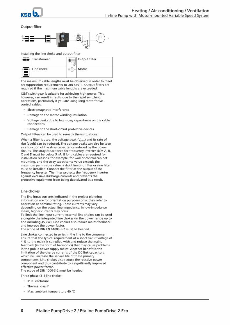
Installing the line choke and output filter
TransformerL
PE
CX
CY R'
R Output filter
Line choke Motor
The maximum cable lengths must be observed in order to meetRFI suppression requirements to DIN 55011. Output filters arerequired if the maximum cable lengths are exceeded.
IGBT switchgear is suitable for achieving high power. This,however, can result in faults due to the rapid switchingoperations, particularly if you are using long motor/drivecontrol cables:
▪ Electromagnetic interference
▪ Damage to the motor winding insulation
▪ Voltage peaks due to high stray capacitance on the cableconnections
▪ Damage to the short-circuit protective devices
Output filters can be used to remedy these situations:
When a filter is used, the voltage peak (Vpeak) and its rate ofrise (dv/dt) can be reduced. The voltage peaks can also be seenas a function of the stray capacitance induced by the powercircuits. The stray capacitance for frequency inverter sizes A, B,C and D must be below 5 nF. If long cables are required forinstallation reasons, for example, for wall or control cabinetmounting, and the stray capacitance value exceeds themaximum permissible value, a dv/dt limiting filter or sine filtermust be installed. Connect the filter at the output of thefrequency inverter. The filter protects the frequency inverteragainst excessive discharge currents and prevents theprotective equipment from being deactivated as a result.
Line chokes
The line input currents indicated in the project planninginformation are for orientation purposes only; they refer tooperation at nominal rating. These currents may varydepending on the actual line impedance. In low-impedancemains, higher currents may occur. To limit the line input current, external line chokes can be usedalongside the integrated line chokes (in the power range up toand including 45 kW). Line chokes also reduce mains feedbackand improve the power factor. The scope of DIN EN 61000-3-2 must be heeded.
Line chokes connected in series in the line to the consumerensure that the typical requirement of a short circuit voltage of4 % to the mains is complied with and reduce the mainsfeedback (in the form of harmonics) that may cause problemsin the public power supply mains. Another benefit is thelimitation of the charge currents of the DC link capacitors,which will increase the service life of these primarycomponents. Line chokes also reduce the reactive powercomponent and thus contribute to a significantly improvedeffective power factor. The scope of DIN 1000-3-2 must be heeded.
Three-phase (3~) line choke:
▪ IP 00 enclosure
▪ Thermal class F
▪ Max. ambient temperature 40 °C
Heating / Air-conditioning / VentilationIn-line Pump with Motor-mounted Variable Speed System
8 Etaline PumpDrive 2 / Etaline PumpDrive 2 Eco
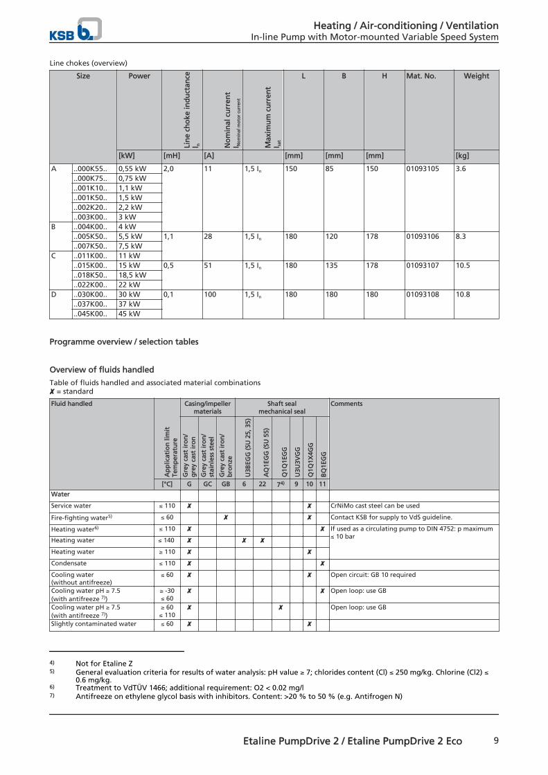
Line chokes (overview)
Size Power
Lin
e ch
oke
ind
uct
ance
l n No
min
al c
urr
ent
I No
min
al m
oto
r cu
rren
t
Max
imu
m c
urr
ent
I sat
L B H Mat. No. Weight
[kW] [mH] [A] [mm] [mm] [mm] [kg]
A ..000K55.. 0,55 kW 2,0 11 1,5 In 150 85 150 01093105 3.6..000K75.. 0,75 kW..001K10.. 1,1 kW..001K50.. 1,5 kW..002K20.. 2,2 kW..003K00.. 3 kW
B ..004K00.. 4 kW..005K50.. 5,5 kW 1,1 28 1,5 In 180 120 178 01093106 8.3..007K50.. 7,5 kW
C ..011K00.. 11 kW..015K00.. 15 kW 0,5 51 1,5 In 180 135 178 01093107 10.5..018K50.. 18,5 kW..022K00.. 22 kW
D ..030K00.. 30 kW 0,1 100 1,5 In 180 180 180 01093108 10.8..037K00.. 37 kW..045K00.. 45 kW
Programme overview / selection tables
Overview of fluids handled
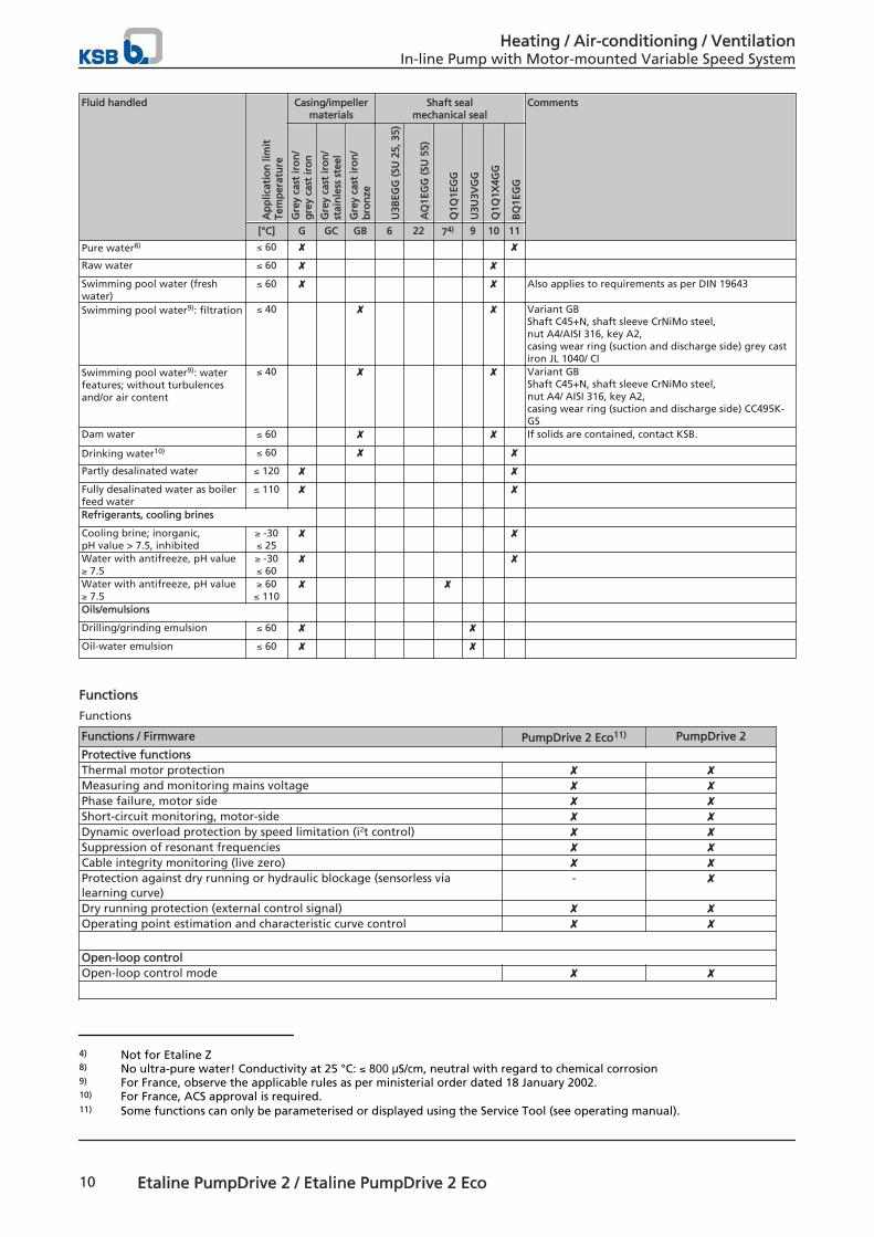
Table of fluids handled and associated material combinations ✘ = standard
Fluid handled
Ap
plic
atio
n li
mit
Tem
per
atu
re
Casing/impellermaterials
Shaft sealmechanical seal
Comments
Gre
y ca
st ir
on
/g
rey
cast
iro
n
Gre
y ca
st ir
on
/st
ain
less
ste
el
Gre
y ca
st ir
on
/b
ron
ze
U3B
EGG
(SU
25,
35)
AQ
1EG
G (
SU 5
5)
Q1Q
1EG
G
U3U
3VG
G
Q1Q
1X4G
G
BQ
1EG
G
[°C] G GC GB 6 22 74) 9 10 11
Water Service water ≤ 110 ✘ ✘ CrNiMo cast steel can be used
Fire-fighting water5) ≤ 60 ✘ ✘ Contact KSB for supply to VdS guideline.
Heating water6) ≤ 110 ✘ ✘ If used as a circulating pump to DIN 4752: p maximum≤ 10 bar
Heating water ≤ 140 ✘ ✘ ✘ Heating water ≥ 110 ✘ ✘ Condensate ≤ 110 ✘ ✘ Cooling water(without antifreeze)
≤ 60 ✘ ✘ Open circuit: GB 10 required
Cooling water pH ≥ 7.5(with antifreeze 7))
≥ -30≤ 60
✘ ✘ Open loop: use GB
Cooling water pH ≥ 7.5(with antifreeze 7))
≥ 60≤ 110
✘ ✘ Open loop: use GB
Slightly contaminated water ≤ 60 ✘ ✘
4) Not for Etaline Z5) General evaluation criteria for results of water analysis: pH value ≥ 7; chlorides content (Cl) ≤ 250 mg/kg. Chlorine (Cl2) ≤
0.6 mg/kg.6) Treatment to VdTÜV 1466; additional requirement: O2 < 0.02 mg/l7) Antifreeze on ethylene glycol basis with inhibitors. Content: >20 % to 50 % (e.g. Antifrogen N)
Heating / Air-conditioning / VentilationIn-line Pump with Motor-mounted Variable Speed System
Etaline PumpDrive 2 / Etaline PumpDrive 2 Eco 9
Fluid handled
Ap
plic
atio
n li
mit
Tem
per
atu
re
Casing/impellermaterials
Shaft sealmechanical seal
Comments
Gre
y ca
st ir
on
/g
rey
cast
iro
n
Gre
y ca
st ir
on
/st
ain
less
ste
el
Gre
y ca
st ir
on
/b
ron
ze
U3B
EGG
(SU
25,
35)
AQ
1EG
G (
SU 5
5)
Q1Q
1EG
G
U3U
3VG
G
Q1Q
1X4G
G
BQ
1EG
G
[°C] G GC GB 6 22 74) 9 10 11
Pure water8) ≤ 60 ✘ ✘ Raw water ≤ 60 ✘ ✘ Swimming pool water (freshwater)
≤ 60 ✘ ✘ Also applies to requirements as per DIN 19643
Swimming pool water9): filtration ≤ 40 ✘ ✘ Variant GBShaft C45+N, shaft sleeve CrNiMo steel, nut A4/AISI 316, key A2, casing wear ring (suction and discharge side) grey castiron JL 1040/ CI
Swimming pool water9): waterfeatures; without turbulencesand/or air content
≤ 40 ✘ ✘ Variant GBShaft C45+N, shaft sleeve CrNiMo steel, nut A4/ AISI 316, key A2, casing wear ring (suction and discharge side) CC495K-GS
Dam water ≤ 60 ✘ ✘ If solids are contained, contact KSB.
Drinking water10) ≤ 60 ✘ ✘ Partly desalinated water ≤ 120 ✘ ✘ Fully desalinated water as boilerfeed water
≤ 110 ✘ ✘ Refrigerants, cooling brines Cooling brine; inorganic, pH value > 7.5, inhibited
≥ -30≤ 25
✘ ✘ Water with antifreeze, pH value≥ 7.5
≥ -30≤ 60
✘ ✘ Water with antifreeze, pH value≥ 7.5
≥ 60≤ 110
✘ ✘ Oils/emulsions Drilling/grinding emulsion ≤ 60 ✘ ✘ Oil-water emulsion ≤ 60 ✘ ✘
Functions
Functions
Functions / Firmware PumpDrive 2 Eco11) PumpDrive 2
Protective functionsThermal motor protection ✘ ✘Measuring and monitoring mains voltage ✘ ✘Phase failure, motor side ✘ ✘Short-circuit monitoring, motor-side ✘ ✘Dynamic overload protection by speed limitation (i2t control) ✘ ✘Suppression of resonant frequencies ✘ ✘Cable integrity monitoring (live zero) ✘ ✘Protection against dry running or hydraulic blockage (sensorless vialearning curve)
- ✘
Dry running protection (external control signal) ✘ ✘Operating point estimation and characteristic curve control ✘ ✘ Open-loop controlOpen-loop control mode ✘ ✘
4) Not for Etaline Z8) No ultra-pure water! Conductivity at 25 °C: ≤ 800 μS/cm, neutral with regard to chemical corrosion9) For France, observe the applicable rules as per ministerial order dated 18 January 2002.10) For France, ACS approval is required.11) Some functions can only be parameterised or displayed using the Service Tool (see operating manual).
Heating / Air-conditioning / VentilationIn-line Pump with Motor-mounted Variable Speed System
10 Etaline PumpDrive 2 / Etaline PumpDrive 2 Eco
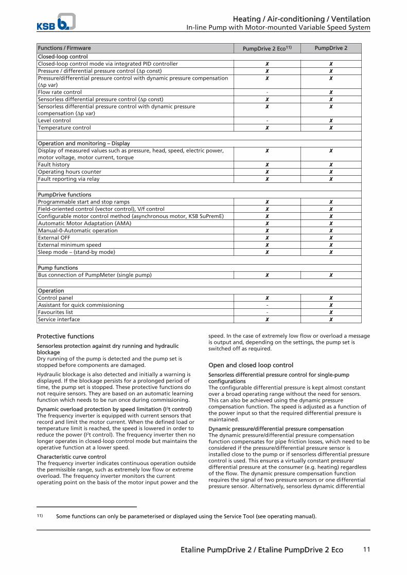
Functions / Firmware PumpDrive 2 Eco11) PumpDrive 2
Closed-loop controlClosed-loop control mode via integrated PID controller ✘ ✘Pressure / differential pressure control (∆p const) ✘ ✘Pressure/differential pressure control with dynamic pressure compensation(∆p var)
✘ ✘
Flow rate control - ✘Sensorless differential pressure control (∆p const) ✘ ✘Sensorless differential pressure control with dynamic pressurecompensation (∆p var)
✘ ✘
Level control - ✘Temperature control ✘ ✘ Operation and monitoring – DisplayDisplay of measured values such as pressure, head, speed, electric power,motor voltage, motor current, torque
✘ ✘
Fault history ✘ ✘Operating hours counter ✘ ✘Fault reporting via relay ✘ ✘ PumpDrive functionsProgrammable start and stop ramps ✘ ✘Field-oriented control (vector control), V/f control ✘ ✘Configurable motor control method (asynchronous motor, KSB SuPremE) ✘ ✘Automatic Motor Adaptation (AMA) ✘ ✘Manual-0-Automatic operation ✘ ✘External OFF ✘ ✘External minimum speed ✘ ✘Sleep mode – (stand-by mode) ✘ ✘ Pump functionsBus connection of PumpMeter (single pump) ✘ ✘ OperationControl panel ✘ ✘Assistant for quick commissioning - ✘Favourites list - ✘Service interface ✘ ✘
Protective functions
Sensorless protection against dry running and hydraulicblockageDry running of the pump is detected and the pump set isstopped before components are damaged.
Hydraulic blockage is also detected and initially a warning isdisplayed. If the blockage persists for a prolonged period oftime, the pump set is stopped. These protective functions donot require sensors. They are based on an automatic learningfunction which needs to be run once during commissioning.
Dynamic overload protection by speed limitation (I2t control) The frequency inverter is equipped with current sensors thatrecord and limit the motor current. When the defined load ortemperature limit is reached, the speed is lowered in order toreduce the power (I2t control). The frequency inverter then nolonger operates in closed-loop control mode but maintains theoperative function at a lower speed.
Characteristic curve controlThe frequency inverter indicates continuous operation outsidethe permissible range, such as extremely low flow or extremeoverload. The frequency inverter monitors the currentoperating point on the basis of the motor input power and the
speed. In the case of extremely low flow or overload a messageis output and, depending on the settings, the pump set isswitched off as required.
Open and closed loop control
Sensorless differential pressure control for single-pumpconfigurationsThe configurable differential pressure is kept almost constantover a broad operating range without the need for sensors.This can also be achieved using the dynamic pressurecompensation function. The speed is adjusted as a function ofthe power input so that the required differential pressure ismaintained.
Dynamic pressure/differential pressure compensationThe dynamic pressure/differential pressure compensationfunction compensates for pipe friction losses, which need to beconsidered if the pressure/differential pressure sensor isinstalled close to the pump or if sensorless differential pressurecontrol is used. This ensures a virtually constant pressure/differential pressure at the consumer (e.g. heating) regardlessof the flow. The dynamic pressure compensation functionrequires the signal of two pressure sensors or one differentialpressure sensor. Alternatively, sensorless dynamic differential
11) Some functions can only be parameterised or displayed using the Service Tool (see operating manual).
Heating / Air-conditioning / VentilationIn-line Pump with Motor-mounted Variable Speed System
Etaline PumpDrive 2 / Etaline PumpDrive 2 Eco 11
pressure compensation can be used. The differential pressuresetpoint is increased as a function of the (estimated ormeasured) flow rate or the speed.
Operation and monitoring
DisplayVarious physical data, such as the pressure, flow rate, speed,motor voltage, motor current, electric power, torque andothers, can be displayed using the control panel or the servicesoftware.
Message historyThe last 100 messages of the frequency inverter can be viewed.All messages are provided with a time stamp (real-time clock).
Statistics function The frequency inverter generates utilisationstatistics on the pump operating hours, drive runtime andnumber of start-ups.
Frequency inverter functions
Motor control methodThe frequency inverter's motor control method can be set foreither an asynchronous motor or the KSB SuPremE motor.
Automatic motor adaptationAutomatic motor adaptation (AMA) is a method for measuringthe electric parameters of the motor with the motor being at astandstill. The frequency inverter's motor control method isoptimised to ensure optimum motor performance andefficiency.
Stand-by mode (sleep mode)Sleep mode allows the single or multiple pump system to beswitched on and off in line with demand. If sleep mode isactivated, the frequency inverter stops the pump in the case oflow flow rates, i.e. when the low flow limit or stop speed isreached. In pressure control applications, an accumulator canbe filled during brief operation with an increased setpointprior to stopping. If a drop in pressure and, thus, a flow raterequirement are detected, the pump restarts.
Pump functions
Direct connection of PumpMeterIn single-pump configurations, PumpMeter can be connectedto the frequency inverter via the Modbus interface using theM12 connector. Once they are connected, the frequencyinverter and PumpMeter can automatically exchange all thedata required for initialisation (pump characteristic curve,sensor data, etc.). This enables easy and straightforwardcommissioning/start-up, even in retrofit applications.
Pressure and temperature limits
Pressure and temperature limits of the pump
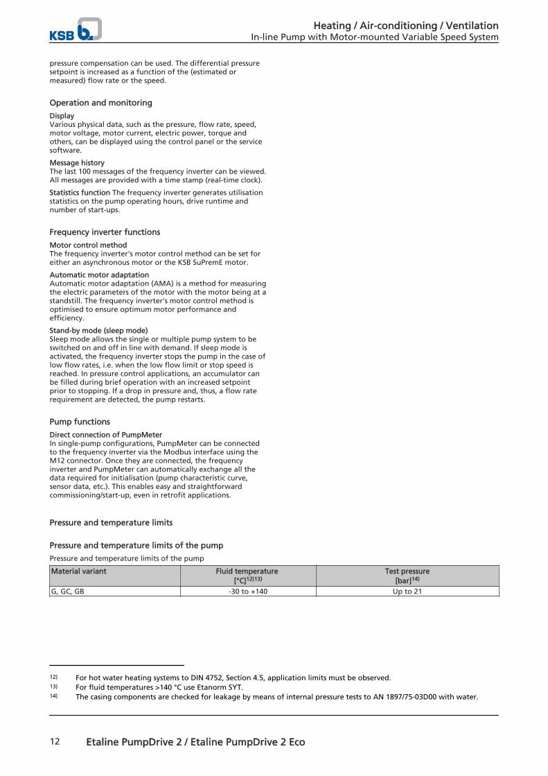
Pressure and temperature limits of the pump
Material variant Fluid temperature [°C]12)13)
Test pressure[bar]14)
G, GC, GB -30 to +140 Up to 21
12) For hot water heating systems to DIN 4752, Section 4.5, application limits must be observed.13) For fluid temperatures >140 °C use Etanorm SYT.14) The casing components are checked for leakage by means of internal pressure tests to AN 1897/75-03D00 with water.
Heating / Air-conditioning / VentilationIn-line Pump with Motor-mounted Variable Speed System
12 Etaline PumpDrive 2 / Etaline PumpDrive 2 Eco
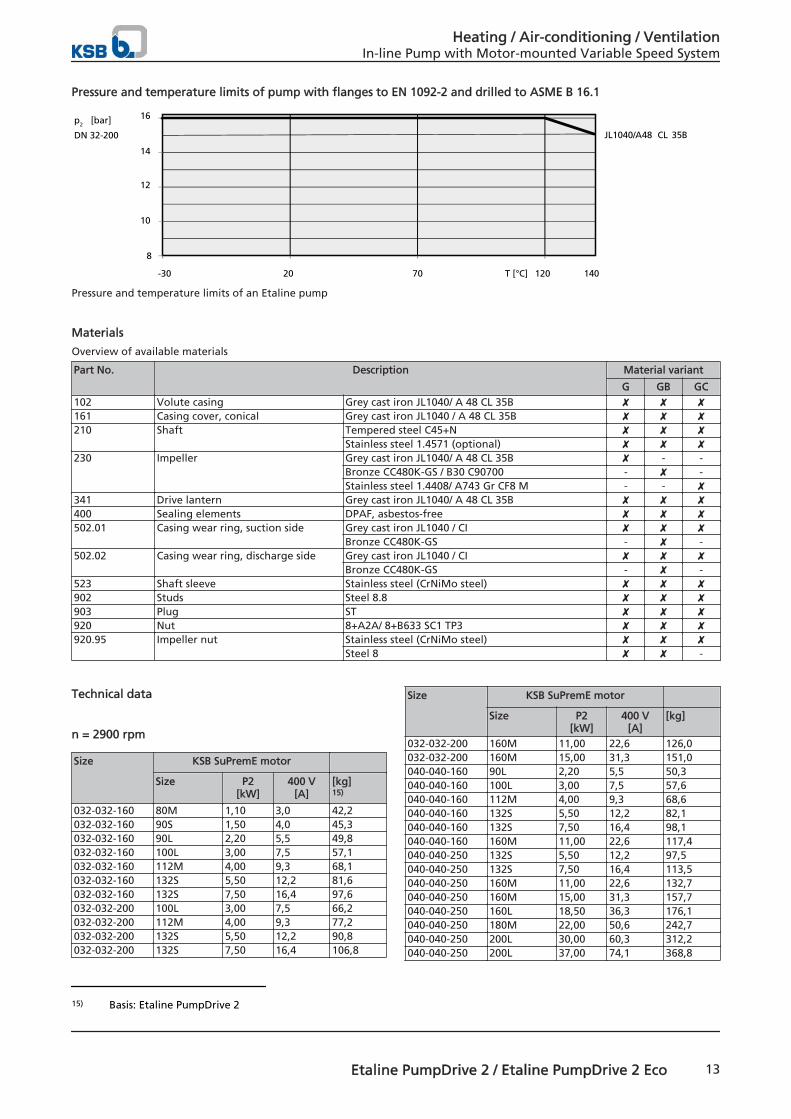
Pressure and temperature limits of pump with flanges to EN 1092-2 and drilled to ASME B 16.1
8
10
12
14
16
-30 20 70 120 140
p2
DN 32-200
[bar] JL1040/A48 CL 35B
T [°C]
Pressure and temperature limits of an Etaline pump
Materials
Overview of available materials
Part No. Description Material variant
G GB GC102 Volute casing Grey cast iron JL1040/ A 48 CL 35B ✘ ✘ ✘161 Casing cover, conical Grey cast iron JL1040 / A 48 CL 35B ✘ ✘ ✘210 Shaft Tempered steel C45+N ✘ ✘ ✘
Stainless steel 1.4571 (optional) ✘ ✘ ✘230 Impeller Grey cast iron JL1040/ A 48 CL 35B ✘ - -
Bronze CC480K-GS / B30 C90700 - ✘ -Stainless steel 1.4408/ A743 Gr CF8 M - - ✘
341 Drive lantern Grey cast iron JL1040/ A 48 CL 35B ✘ ✘ ✘400 Sealing elements DPAF, asbestos-free ✘ ✘ ✘502.01 Casing wear ring, suction side Grey cast iron JL1040 / CI ✘ ✘ ✘
Bronze CC480K-GS - ✘ -502.02 Casing wear ring, discharge side Grey cast iron JL1040 / CI ✘ ✘ ✘
Bronze CC480K-GS - ✘ -523 Shaft sleeve Stainless steel (CrNiMo steel) ✘ ✘ ✘902 Studs Steel 8.8 ✘ ✘ ✘903 Plug ST ✘ ✘ ✘920 Nut 8+A2A/ 8+B633 SC1 TP3 ✘ ✘ ✘920.95 Impeller nut Stainless steel (CrNiMo steel) ✘ ✘ ✘
Steel 8 ✘ ✘ -
Technical data
n = 2900 rpm
Size KSB SuPremE motor Size P2
[kW]400 V
[A][kg]15)
032-032-160 80M 1,10 3,0 42,2032-032-160 90S 1,50 4,0 45,3032-032-160 90L 2,20 5,5 49,8032-032-160 100L 3,00 7,5 57,1032-032-160 112M 4,00 9,3 68,1032-032-160 132S 5,50 12,2 81,6032-032-160 132S 7,50 16,4 97,6032-032-200 100L 3,00 7,5 66,2032-032-200 112M 4,00 9,3 77,2032-032-200 132S 5,50 12,2 90,8032-032-200 132S 7,50 16,4 106,8
Size KSB SuPremE motor Size P2
[kW]400 V
[A][kg]
032-032-200 160M 11,00 22,6 126,0032-032-200 160M 15,00 31,3 151,0040-040-160 90L 2,20 5,5 50,3040-040-160 100L 3,00 7,5 57,6040-040-160 112M 4,00 9,3 68,6040-040-160 132S 5,50 12,2 82,1040-040-160 132S 7,50 16,4 98,1040-040-160 160M 11,00 22,6 117,4040-040-250 132S 5,50 12,2 97,5040-040-250 132S 7,50 16,4 113,5040-040-250 160M 11,00 22,6 132,7040-040-250 160M 15,00 31,3 157,7040-040-250 160L 18,50 36,3 176,1040-040-250 180M 22,00 50,6 242,7040-040-250 200L 30,00 60,3 312,2040-040-250 200L 37,00 74,1 368,8
15) Basis: Etaline PumpDrive 2
Heating / Air-conditioning / VentilationIn-line Pump with Motor-mounted Variable Speed System
Etaline PumpDrive 2 / Etaline PumpDrive 2 Eco 13
Size KSB SuPremE motor Size P2
[kW]400 V
[A][kg]15)
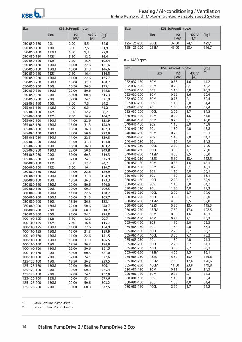
050-050-160 90L 2,20 5,5 54,6050-050-160 100L 3,00 7,5 61,9050-050-160 112M 4,00 9,3 72,9050-050-160 132S 5,50 12,2 86,4050-050-160 132S 7,50 16,4 102,4050-050-160 160M 11,00 22,6 121,6050-050-160 160M 15,00 31,3 146,6050-050-250 132S 7,50 16,4 116,5050-050-250 160M 11,00 22,6 135,7050-050-250 160M 15,00 31,3 160,7050-050-250 160L 18,50 36,3 179,1050-050-250 180M 22,00 50,6 245,8050-050-250 200L 30,00 60,3 315,3050-050-250 200L 37,00 74,1 371,9065-065-160 100L 3,00 7,5 64,2065-065-160 112M 4,00 9,3 75,2065-065-160 132S 5,50 12,2 88,7065-065-160 132S 7,50 16,4 104,7065-065-160 160M 11,00 22,6 123,9065-065-160 160M 15,00 31,3 148,9065-065-160 160L 18,50 36,3 167,3065-065-160 180M 22,00 50,6 233,9065-065-250 160M 11,00 22,6 139,8065-065-250 160M 15,00 31,3 164,8065-065-250 160L 18,50 36,3 183,2065-065-250 180M 22,00 50,6 249,8065-065-250 200L 30,00 60,3 319,3065-065-250 200L 37,00 74,1 375,9080-080-160 132S 5,50 12,2 94,7080-080-160 132S 7,50 16,4 110,7080-080-160 160M 11,00 22,6 129,9080-080-160 160M 15,00 31,3 154,9080-080-160 160L 18,50 36,3 173,3080-080-160 180M 22,00 50,6 240,0080-080-160 200L 30,00 60,3 309,5080-080-200 160M 11,00 22,6 138,7080-080-200 160M 15,00 31,3 163,7080-080-200 160L 18,50 36,3 182,1080-080-200 180M 22,00 50,6 248,7080-080-200 200L 30,00 60,3 318,2080-080-200 200L 37,00 74,1 374,8100-100-125 132S 5,50 12,2 99,7100-100-125 132S 7,50 16,4 115,7100-100-125 160M 11,00 22,6 134,9100-100-125 160M 15,00 31,3 159,9100-100-160 160M 11,00 22,6 141,5100-100-160 160M 15,00 31,3 166,5100-100-160 160L 18,50 36,3 184,9100-100-160 180M 22,00 50,6 251,5100-100-160 200L 30,00 60,3 321,0100-100-160 200L 37,00 74,1 377,6125-125-160 160L 18,50 36,3 239,5125-125-160 180M 22,00 50,6 306,1125-125-160 200L 30,00 60,3 375,4125-125-160 200L 37,00 74,1 432,0125-125-160 225M 45,00 93,4 579,6125-125-200 180M 22,00 50,6 303,2125-125-200 200L 30,00 60,3 372,5
Size KSB SuPremE motor Size P2
[kW]400 V
[A][kg]
125-125-200 200L 37,00 74,1 429,1125-125-200 225M 45,00 93,4 576,7
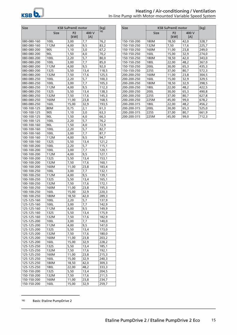
n = 1450 rpm
Size KSB SuPremE motor [kg]16)
Size P2[kW]
400 V[A]
032-032-160 80M 0,55 1,6 41,2032-032-160 80M 0,75 2,1 43,2032-032-160 90S 1,10 3,0 45,3032-032-200 80M 0,55 1,6 50,4032-032-200 80M 0,75 2,1 52,4032-032-200 90S 1,10 3,0 54,4032-032-200 90L 1,50 4,0 57,4032-032-200 100L 2,20 5,7 67,2040-040-160 80M 0,55 1,6 41,8040-040-160 80M 0,75 2,1 43,8040-040-160 90S 1,10 3,0 45,8040-040-160 90L 1,50 4,0 48,8040-040-250 80M 0,75 2,1 59,1040-040-250 90S 1,10 3,0 61,2040-040-250 90L 1,50 4,0 64,2040-040-250 100L 2,20 5,7 74,0040-040-250 100L 3,00 7,7 79,0040-040-250 112M 4,00 9,5 86,0040-040-250 132S 5,50 13,4 112,5050-050-160 80M 0,55 1,6 46,1050-050-160 80M 0,75 2,1 48,1050-050-160 90S 1,10 3,0 50,1050-050-160 90L 1,50 4,0 53,1050-050-160 100L 2,20 5,7 62,9050-050-250 90S 1,10 3,0 64,2050-050-250 90L 1,50 4,0 67,2050-050-250 100L 2,20 5,7 77,0050-050-250 100L 3,00 7,7 92,0050-050-250 112M 4,00 9,5 89,0050-050-250 132S 5,50 13,4 115,5050-050-250 132M 7,50 17,6 122,5065-065-160 80M 0,55 1,6 48,3065-065-160 80M 0,75 2,1 50,3065-065-160 90S 1,10 3,0 52,3065-065-160 90L 1,50 4,0 55,3065-065-160 100L 2,20 5,7 65,2065-065-160 100L 3,00 7,7 70,2065-065-250 90L 1,50 4,0 71,3065-065-250 100L 2,20 5,7 81,1065-065-250 100L 3,00 7,7 86,1065-065-250 112M 4,00 9,5 93,1065-065-250 132S 5,50 13,4 119,6065-065-250 132M 7,50 17,6 126,6065-065-250 160M 11,00 23,8 149,8080-080-160 80M 0,55 1,6 54,3080-080-160 80M 0,75 2,1 56,3080-080-160 90S 1,10 3,0 58,4080-080-160 90L 1,50 4,0 61,4080-080-160 100L 2,20 5,7 71,2
15) Basis: Etaline PumpDrive 216) Basis: Etaline PumpDrive 2
Heating / Air-conditioning / VentilationIn-line Pump with Motor-mounted Variable Speed System
14 Etaline PumpDrive 2 / Etaline PumpDrive 2 Eco
Size KSB SuPremE motor [kg]16)
Size P2[kW]
400 V[A]
080-080-160 100L 3,00 7,7 76,2080-080-160 112M 4,00 9,5 83,2080-080-200 90S 1,10 3,0 67,2080-080-200 90L 1,50 4,0 70,2080-080-200 100L 2,20 5,7 80,0080-080-200 100L 3,00 7,7 85,0080-080-200 112M 4,00 9,5 92,0080-080-200 132S 5,50 13,4 118,5080-080-200 132M 7,50 17,6 125,5080-080-250 100L 2,20 5,7 100,3080-080-250 100L 3,00 7,7 105,3080-080-250 112M 4,00 9,5 112,3080-080-250 132S 5,50 13,4 138,3080-080-250 132M 7,50 17,6 145,3080-080-250 160M 11,00 23,8 168,5080-080-250 160L 15,00 32,9 193,5100-100-125 80M 0,75 2,1 61,3100-100-125 90S 1,10 3,0 63,3100-100-125 90L 1,50 4,0 66,3100-100-125 100L 2,20 5,7 76,2100-100-160 90L 1,50 4,0 72,9100-100-160 100L 2,20 5,7 82,7100-100-160 100L 3,00 7,7 87,7100-100-160 112M 4,00 9,5 94,7100-100-160 132S 5,50 13,4 121,2100-100-200 100L 2,20 5,7 115,1100-100-200 100L 3,00 7,7 120,1100-100-200 112M 4,00 9,5 127,1100-100-200 132S 5,50 13,4 153,1100-100-200 132M 7,50 17,6 160,1100-100-200 160M 11,00 23,8 183,4100-100-250 100L 3,00 7,7 132,1100-100-250 112M 4,00 9,5 139,1100-100-250 132S 5,50 13,4 165,1100-100-250 132M 7,50 17,6 172,1100-100-250 160M 11,00 23,8 195,3100-100-250 160L 15,00 32,9 220,3100-100-250 180M 18,50 42,0 289,3125-125-160 100L 2,20 5,7 137,9125-125-160 100L 3,00 7,7 142,9125-125-160 112M 4,00 9,5 149,9125-125-160 132S 5,50 13,4 175,9125-125-160 132M 7,50 17,6 182,9125-125-200 100L 3,00 7,7 140,0125-125-200 112M 4,00 9,5 147,0125-125-200 132S 5,50 13,4 173,0125-125-200 132M 7,50 17,6 180,0125-125-200 160M 11,00 23,8 203,2125-125-200 160L 15,00 32,9 228,2125-125-250 132S 5,50 13,4 185,1125-125-250 132M 7,50 17,6 192,1125-125-250 160M 11,00 23,8 215,3125-125-250 160L 15,00 32,9 240,3125-125-250 180M 18,50 42,0 309,3125-125-250 180L 22,00 48,2 333,3150-150-200 132S 5,50 13,4 204,5150-150-200 132M 7,50 17,6 211,5150-150-200 160M 11,00 23,8 234,7150-150-200 160L 15,00 32,9 259,7
Size KSB SuPremE motor [kg]
Size P2[kW]
400 V[A]
150-150-200 180M 18,50 42,0 328,7150-150-250 132M 7,50 17,6 225,7150-150-250 160M 11,00 23,8 249,0150-150-250 160L 15,00 32,9 274,0150-150-250 180M 18,50 42,0 343,0150-150-250 180L 22,00 48,2 367,0150-150-250 200L 30,00 65,3 435,3150-150-250 225S 37,00 80,7 572,3200-200-250 160M 11,00 23,8 304,5200-200-250 160L 15,00 32,9 329,5200-200-250 180M 18,50 32,9 398,5200-200-250 180L 22,00 48,2 422,5200-200-250 200L 30,00 65,3 490,8200-200-250 225S 37,00 80,7 627,8200-200-250 225M 45,00 99,0 678,2200-200-315 180L 22,00 48,2 456,2200-200-315 200L 30,00 65,3 525,0200-200-315 225S 37,00 80,7 661,9200-200-315 225M 45,00 99,0 712,3
16) Basis: Etaline PumpDrive 2
Heating / Air-conditioning / VentilationIn-line Pump with Motor-mounted Variable Speed System
Etaline PumpDrive 2 / Etaline PumpDrive 2 Eco 15
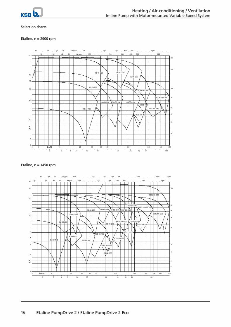
Selection charts
Etaline, n = 2900 rpm
H[m]
Q[m³/h]4 5 10 20 30 40 50 100 200 300 400Q[m³/h]
20 30 40 50 100 200 300 400 500 1000US.gpm
20 30 40 50 100 200 300 400 500 1000IM.gpm
4
5
10
20
30
40
50
100
H[m]
20
30
40
50
100
200
300
ft
2 3 4 5 10 20 30 40 50 100l/s
125-125-160
100-100-160
80-80-200
80-80-160
100-100-125
65-65-250
65-65-160
50-50-250
50-50-16040-40-160
40-40-250
32-32-200
32-32-160
Etaline, n = 1450 rpm
H[m]
Q[m³/h]5 10 20 30 40 50 100 200 300 400 500 700Q[m³/h]
30 40 50 100 200 300 400 500 1000 2000 3000US.gpm
20 30 40 50 100 200 300 400 500 1000 2000IM.gpm
1
2
3
4
5
10
20
30
40
H[m]
4
5
10
20
30
40
50
100
ft
2 3 4 5 10 20 30 40 50 100l/s
200-200-315
80-80-160
200-200-250
150-150-250
150-150-200
125-125-250
125-125-200
125-125-160
100-100-250
100-100-200
100-100-160
80-80-250
80-80-200
100-100-125
65-65-250
65-65-160
50-50-250
50-50-160
40-40-160
32-32-160
40-40-250
32-32-200
Heating / Air-conditioning / VentilationIn-line Pump with Motor-mounted Variable Speed System
16 Etaline PumpDrive 2 / Etaline PumpDrive 2 Eco
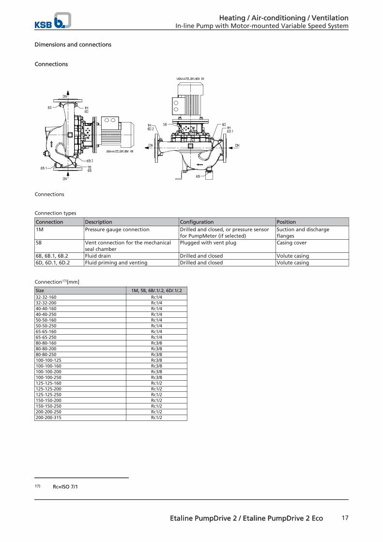
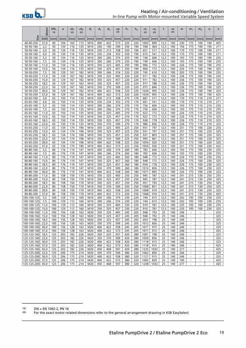
Dimensions and connections
Connections
Connections
Connection types
Connection Description Configuration Position1M Pressure gauge connection Drilled and closed, or pressure sensor
for PumpMeter (if selected)Suction and dischargeflanges
5B Vent connection for the mechanicalseal chamber
Plugged with vent plug Casing cover
6B, 6B.1, 6B.2 Fluid drain Drilled and closed Volute casing6D, 6D.1, 6D.2 Fluid priming and venting Drilled and closed Volute casing
Connection17)[mm]
Size 1M, 5B, 6B/.1/.2, 6D/.1/.2
32-32-160 Rc1/432-32-200 Rc1/440-40-160 Rc1/440-40-250 Rc1/450-50-160 Rc1/450-50-250 Rc1/465-65-160 Rc1/465-65-250 Rc1/480-80-160 Rc3/880-80-200 Rc3/880-80-250 Rc3/8100-100-125 Rc3/8100-100-160 Rc3/8100-100-200 Rc3/8100-100-250 Rc3/8125-125-160 Rc1/2125-125-200 Rc1/2125-125-250 Rc1/2150-150-200 Rc1/2150-150-250 Rc1/2200-200-250 Rc1/2200-200-315 Rc1/2
17) Rc=ISO 7/1
Heating / Air-conditioning / VentilationIn-line Pump with Motor-mounted Variable Speed System
Etaline PumpDrive 2 / Etaline PumpDrive 2 Eco 17
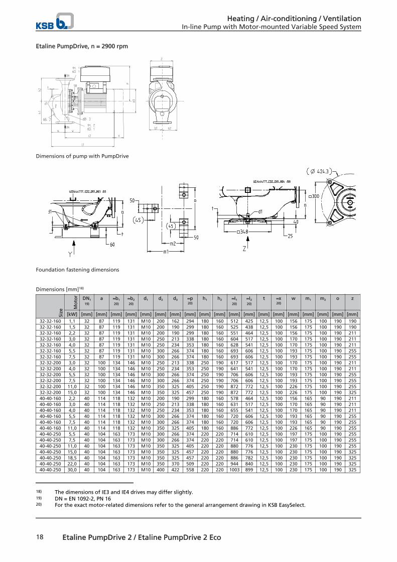
Etaline PumpDrive, n = 2900 rpm
Dimensions of pump with PumpDrive
Foundation fastening dimensions
Dimensions [mm]18)
Size
Mo
tor DN1
19)
a ≈b1
20)
≈b2
20)
d1 d2 d3 ≈p20)
h1 h2 ≈I1
20)
≈I2
20)
t ≈x20)
w m1 m2 o z
[kW] [mm] [mm] [mm] [mm] [mm] [mm] [mm] [mm] [mm] [mm] [mm] [mm] [mm] [mm] [mm] [mm] [mm] [mm] [mm]
32-32-160 1,1 32 87 119 131 M10 200 162 294 180 160 512 425 12,5 100 156 175 100 190 19032-32-160 1,5 32 87 119 131 M10 200 190 299 180 160 525 438 12,5 100 156 175 100 190 19032-32-160 2,2 32 87 119 131 M10 200 190 299 180 160 551 464 12,5 100 156 175 100 190 21132-32-160 3,0 32 87 119 131 M10 250 213 338 180 160 604 517 12,5 100 170 175 100 190 21132-32-160 4,0 32 87 119 131 M10 250 234 353 180 160 628 541 12,5 100 170 175 100 190 21132-32-160 5,5 32 87 119 131 M10 300 266 374 180 160 693 606 12,5 100 193 175 100 190 25532-32-160 7,5 32 87 119 131 M10 300 266 374 180 160 693 606 12,5 100 193 175 100 190 25532-32-200 3,0 32 100 134 146 M10 250 213 338 250 190 617 517 12,5 100 170 175 100 190 21132-32-200 4,0 32 100 134 146 M10 250 234 353 250 190 641 541 12,5 100 170 175 100 190 21132-32-200 5,5 32 100 134 146 M10 300 266 374 250 190 706 606 12,5 100 193 175 100 190 25532-32-200 7,5 32 100 134 146 M10 300 266 374 250 190 706 606 12,5 100 193 175 100 190 25532-32-200 11,0 32 100 134 146 M10 350 325 405 250 190 872 772 12,5 100 226 175 100 190 25532-32-200 15,0 32 100 134 146 M10 350 325 457 250 190 872 772 12,5 100 226 175 100 190 32540-40-160 2,2 40 114 118 132 M10 200 190 299 180 160 578 464 12,5 100 156 165 90 190 21140-40-160 3,0 40 114 118 132 M10 250 213 338 180 160 631 517 12,5 100 170 165 90 190 21140-40-160 4,0 40 114 118 132 M10 250 234 353 180 160 655 541 12,5 100 170 165 90 190 21140-40-160 5,5 40 114 118 132 M10 300 266 374 180 160 720 606 12,5 100 193 165 90 190 25540-40-160 7,5 40 114 118 132 M10 300 266 374 180 160 720 606 12,5 100 193 165 90 190 25540-40-160 11,0 40 114 118 132 M10 350 325 405 180 160 886 772 12,5 100 226 165 90 190 25540-40-250 5,5 40 104 163 173 M10 300 266 374 220 220 714 610 12,5 100 197 175 100 190 25540-40-250 7,5 40 104 163 173 M10 300 266 374 220 220 714 610 12,5 100 197 175 100 190 25540-40-250 11,0 40 104 163 173 M10 350 325 405 220 220 880 776 12,5 100 230 175 100 190 25540-40-250 15,0 40 104 163 173 M10 350 325 457 220 220 880 776 12,5 100 230 175 100 190 32540-40-250 18,5 40 104 163 173 M10 350 325 457 220 220 886 782 12,5 100 230 175 100 190 32540-40-250 22,0 40 104 163 173 M10 350 370 509 220 220 944 840 12,5 100 230 175 100 190 32540-40-250 30,0 40 104 163 173 M10 400 422 558 220 220 1003 899 12,5 100 230 175 100 190 325
18) The dimensions of IE3 and IE4 drives may differ slightly.19) DN = EN 1092-2, PN 1620) For the exact motor-related dimensions refer to the general arrangement drawing in KSB EasySelect.
Heating / Air-conditioning / VentilationIn-line Pump with Motor-mounted Variable Speed System
18 Etaline PumpDrive 2 / Etaline PumpDrive 2 Eco
Size
Mo
tor DN1
19)
a ≈b1
20)
≈b2
20)
d1 d2 d3 ≈p20)
h1 h2 ≈I1
20)
≈I2
20)
t ≈x20)
w m1 m2 o z
[kW] [mm] [mm] [mm] [mm] [mm] [mm] [mm] [mm] [mm] [mm] [mm] [mm] [mm] [mm] [mm] [mm] [mm] [mm] [mm]
40-40-250 37,0 40 104 163 173 M10 400 422 573 220 220 1003 899 12,5 100 230 175 100 190 42550-50-160 2,2 50 134 116 135 M10 200 190 299 250 190 598 464 12,5 100 156 175 100 190 21150-50-160 3,0 50 134 116 135 M10 250 213 338 250 190 651 517 12,5 100 170 175 100 190 21150-50-160 4,0 50 134 116 135 M10 250 234 353 250 190 675 541 12,5 100 170 175 100 190 21150-50-160 5,5 50 134 116 135 M10 300 266 374 250 190 740 606 12,5 100 193 175 100 190 25550-50-160 7,5 50 134 116 135 M10 300 266 374 250 190 740 606 12,5 100 193 175 100 190 25550-50-160 11,0 50 134 116 135 M10 350 325 405 250 190 906 772 12,5 100 226 175 100 190 25550-50-160 15,0 50 134 116 135 M10 350 325 457 250 190 906 772 12,5 100 226 175 100 190 32550-50-250 7,5 50 129 167 182 M10 300 266 374 220 220 745 616 12,5 100 203 175 100 190 25550-50-250 11,0 50 129 167 182 M10 350 325 405 220 220 911 782 12,5 100 236 175 100 190 25550-50-250 15,0 50 129 167 182 M10 350 325 457 220 220 911 782 12,5 100 236 175 100 190 32550-50-250 18,5 50 129 167 182 M10 350 325 457 220 220 917 788 12,5 100 236 175 100 190 32550-50-250 22,0 50 129 167 182 M10 350 370 509 220 220 975 846 12,5 100 236 175 100 190 32550-50-250 30,0 50 129 167 182 M10 400 422 558 220 220 1034 905 12,5 100 236 175 100 190 32550-50-250 37,0 50 129 167 182 M10 400 422 573 220 220 1034 905 12,5 100 236 175 100 190 42565-65-160 3,0 65 150 114 135 M10 250 213 338 270 170 667 517 12,5 100 170 175 110 210 21165-65-160 4,0 65 150 114 135 M10 250 234 353 270 170 691 541 12,5 100 170 175 110 210 21165-65-160 5,5 65 150 114 135 M10 300 266 374 270 170 756 606 12,5 100 193 175 110 210 25565-65-160 7,5 65 150 114 135 M10 300 266 374 270 170 756 606 12,5 100 193 175 110 210 25565-65-160 11,0 65 150 114 135 M10 350 325 405 270 170 922 772 12,5 100 226 175 110 210 25565-65-160 15,0 65 150 114 135 M10 350 325 457 270 170 922 772 12,5 100 226 175 110 210 32565-65-160 18,5 65 150 114 135 M10 350 325 457 270 170 928 778 12,5 100 226 175 110 210 32565-65-160 22,0 65 150 114 135 M10 350 370 509 270 170 986 836 12,5 100 226 175 110 210 32565-65-250 11,0 65 134 174 196 M10 350 325 405 225 250 931 797 12,5 100 251 175 100 220 25565-65-250 15,0 65 134 174 196 M10 350 325 457 225 250 931 797 12,5 100 251 175 100 220 32565-65-250 18,5 65 134 174 196 M10 350 325 457 225 250 937 803 12,5 100 251 175 100 220 32565-65-250 22,0 65 134 174 196 M10 350 370 509 225 250 995 861 12,5 100 251 175 100 220 32565-65-250 30,0 65 134 174 196 M10 400 422 558 225 250 1054 920 12,5 100 251 175 100 220 32565-65-250 37,0 65 134 174 196 M10 400 422 573 225 250 1054 920 12,5 100 251 175 100 220 42580-80-160 5,5 80 176 119 147 M10 300 266 374 260 180 782 606 12,5 100 193 175 100 230 25580-80-160 7,5 80 176 119 147 M10 300 266 374 260 180 782 606 12,5 100 193 175 100 230 25580-80-160 11,0 80 176 119 147 M10 350 325 405 260 180 948 772 12,5 100 226 175 100 230 25580-80-160 15,0 80 176 119 147 M10 350 325 457 260 180 948 772 12,5 100 226 175 100 230 32580-80-160 18,5 80 176 119 147 M10 350 325 457 260 180 954 778 12,5 100 226 175 100 230 32580-80-160 22,0 80 176 119 147 M10 350 370 509 260 180 1012 836 12,5 100 226 175 100 230 32580-80-160 30,0 80 176 119 147 M10 400 422 558 260 180 1071 895 12,5 100 226 175 100 230 32580-80-200 11,0 80 158 150 170 M10 350 325 405 250 250 945 787 12,5 140 241 215 130 250 25580-80-200 15,0 80 158 150 170 M10 350 325 457 250 250 945 787 12,5 140 241 215 130 250 32580-80-200 18,5 80 158 150 170 M10 350 325 457 250 250 951 793 12,5 140 241 215 130 250 32580-80-200 22,0 80 158 150 170 M10 350 370 509 250 250 1009 851 12,5 140 241 215 130 250 32580-80-200 30,0 80 158 150 170 M10 400 422 558 250 250 1068 910 12,5 140 241 215 130 250 32580-80-200 37,0 80 158 150 170 M10 400 422 573 250 250 1068 910 12,5 140 241 215 130 250 425
100-100-125 5,5 100 129 112 160 M10 300 266 374 230 220 744 615 12,5 100 202 195 100 230 255100-100-125 7,5 100 129 112 160 M10 300 266 374 230 220 744 615 12,5 100 202 195 100 230 255100-100-125 11,0 100 129 112 160 M10 350 325 405 230 220 910 781 12,5 100 235 195 100 230 255100-100-125 15,0 100 129 112 160 M10 350 325 457 230 220 910 781 12,5 100 235 195 100 230 325100-100-160 11,0 100 156 128 163 M20 350 325 405 245 205 948 792 25 140 246 - - - 255100-100-160 15,0 100 156 128 163 M20 350 325 457 245 205 948 792 25 140 246 - - - 325100-100-160 18,5 100 156 128 163 M20 350 325 457 245 205 954 798 25 140 246 - - - 325100-100-160 22,0 100 156 128 163 M20 350 370 509 245 205 1012 856 25 140 246 - - - 325100-100-160 30,0 100 156 128 163 M20 400 422 558 245 205 1071 915 25 140 246 - - - 325100-100-160 37,0 100 156 128 163 M20 400 422 573 245 205 1071 915 25 140 246 - - - 425125-125-160 18,5 125 203 182 226 M20 350 325 457 420 280 1001 798 25 140 246 - - - 325125-125-160 22,0 125 203 182 226 M20 350 370 509 420 280 1059 856 25 140 246 - - - 325125-125-160 30,0 125 203 182 226 M20 400 422 558 420 280 1118 915 25 140 246 - - - 325125-125-160 37,0 125 203 182 226 M20 400 422 573 420 280 1118 915 25 140 246 - - - 425125-125-160 45,0 125 203 182 226 M20 450 468 597 420 280 1235 1032 25 140 277 - - - 425125-125-200 22,0 125 206 175 214 M20 350 370 509 380 320 1062 856 25 140 246 - - - 325125-125-200 30,0 125 206 175 214 M20 400 422 558 380 320 1121 915 25 140 246 - - - 325125-125-200 37,0 125 206 175 214 M20 400 422 573 380 320 1065 859 25 140 190 - - - 425125-125-200 45,0 125 206 175 214 M20 450 468 597 380 320 1238 1032 25 140 277 - - - 425
19) DN = EN 1092-2, PN 1620) For the exact motor-related dimensions refer to the general arrangement drawing in KSB EasySelect.
Heating / Air-conditioning / VentilationIn-line Pump with Motor-mounted Variable Speed System
Etaline PumpDrive 2 / Etaline PumpDrive 2 Eco 19
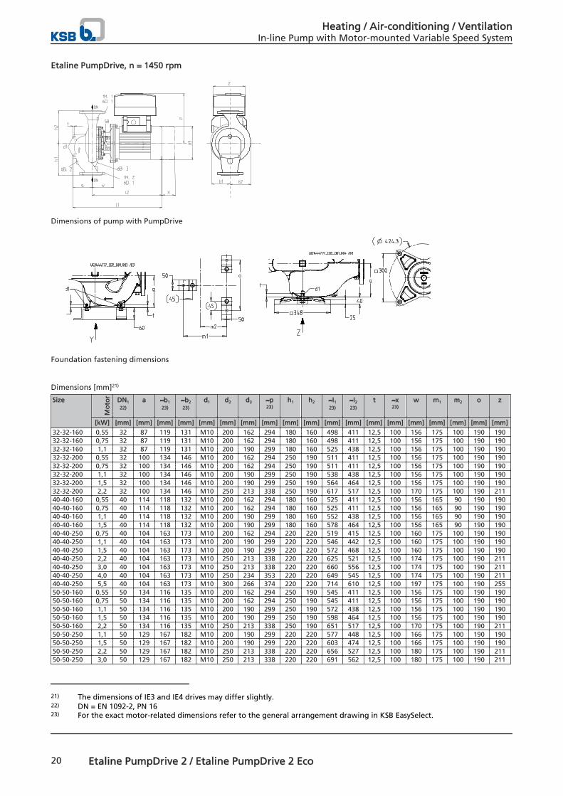
Etaline PumpDrive, n = 1450 rpm
Dimensions of pump with PumpDrive
Foundation fastening dimensions
Dimensions [mm]21)
Size
Mo
tor DN1
22)
a ≈b1
23)
≈b2
23)
d1 d2 d3 ≈p23)
h1 h2 ≈I1
23)
≈I2
23)
t ≈x23)
w m1 m2 o z
[kW] [mm] [mm] [mm] [mm] [mm] [mm] [mm] [mm] [mm] [mm] [mm] [mm] [mm] [mm] [mm] [mm] [mm] [mm] [mm]
32-32-160 0,55 32 87 119 131 M10 200 162 294 180 160 498 411 12,5 100 156 175 100 190 19032-32-160 0,75 32 87 119 131 M10 200 162 294 180 160 498 411 12,5 100 156 175 100 190 19032-32-160 1,1 32 87 119 131 M10 200 190 299 180 160 525 438 12,5 100 156 175 100 190 19032-32-200 0,55 32 100 134 146 M10 200 162 294 250 190 511 411 12,5 100 156 175 100 190 19032-32-200 0,75 32 100 134 146 M10 200 162 294 250 190 511 411 12,5 100 156 175 100 190 19032-32-200 1,1 32 100 134 146 M10 200 190 299 250 190 538 438 12,5 100 156 175 100 190 19032-32-200 1,5 32 100 134 146 M10 200 190 299 250 190 564 464 12,5 100 156 175 100 190 19032-32-200 2,2 32 100 134 146 M10 250 213 338 250 190 617 517 12,5 100 170 175 100 190 21140-40-160 0,55 40 114 118 132 M10 200 162 294 180 160 525 411 12,5 100 156 165 90 190 19040-40-160 0,75 40 114 118 132 M10 200 162 294 180 160 525 411 12,5 100 156 165 90 190 19040-40-160 1,1 40 114 118 132 M10 200 190 299 180 160 552 438 12,5 100 156 165 90 190 19040-40-160 1,5 40 114 118 132 M10 200 190 299 180 160 578 464 12,5 100 156 165 90 190 19040-40-250 0,75 40 104 163 173 M10 200 162 294 220 220 519 415 12,5 100 160 175 100 190 19040-40-250 1,1 40 104 163 173 M10 200 190 299 220 220 546 442 12,5 100 160 175 100 190 19040-40-250 1,5 40 104 163 173 M10 200 190 299 220 220 572 468 12,5 100 160 175 100 190 19040-40-250 2,2 40 104 163 173 M10 250 213 338 220 220 625 521 12,5 100 174 175 100 190 21140-40-250 3,0 40 104 163 173 M10 250 213 338 220 220 660 556 12,5 100 174 175 100 190 21140-40-250 4,0 40 104 163 173 M10 250 234 353 220 220 649 545 12,5 100 174 175 100 190 21140-40-250 5,5 40 104 163 173 M10 300 266 374 220 220 714 610 12,5 100 197 175 100 190 25550-50-160 0,55 50 134 116 135 M10 200 162 294 250 190 545 411 12,5 100 156 175 100 190 19050-50-160 0,75 50 134 116 135 M10 200 162 294 250 190 545 411 12,5 100 156 175 100 190 19050-50-160 1,1 50 134 116 135 M10 200 190 299 250 190 572 438 12,5 100 156 175 100 190 19050-50-160 1,5 50 134 116 135 M10 200 190 299 250 190 598 464 12,5 100 156 175 100 190 19050-50-160 2,2 50 134 116 135 M10 250 213 338 250 190 651 517 12,5 100 170 175 100 190 21150-50-250 1,1 50 129 167 182 M10 200 190 299 220 220 577 448 12,5 100 166 175 100 190 19050-50-250 1,5 50 129 167 182 M10 200 190 299 220 220 603 474 12,5 100 166 175 100 190 19050-50-250 2,2 50 129 167 182 M10 250 213 338 220 220 656 527 12,5 100 180 175 100 190 21150-50-250 3,0 50 129 167 182 M10 250 213 338 220 220 691 562 12,5 100 180 175 100 190 211
21) The dimensions of IE3 and IE4 drives may differ slightly.22) DN = EN 1092-2, PN 1623) For the exact motor-related dimensions refer to the general arrangement drawing in KSB EasySelect.
Heating / Air-conditioning / VentilationIn-line Pump with Motor-mounted Variable Speed System
20 Etaline PumpDrive 2 / Etaline PumpDrive 2 Eco
Size
Mo
tor DN1
22)
a ≈b1
23)
≈b2
23)
d1 d2 d3 ≈p23)
h1 h2 ≈I1
23)
≈I2
23)
t ≈x23)
w m1 m2 o z
[kW] [mm] [mm] [mm] [mm] [mm] [mm] [mm] [mm] [mm] [mm] [mm] [mm] [mm] [mm] [mm] [mm] [mm] [mm] [mm]
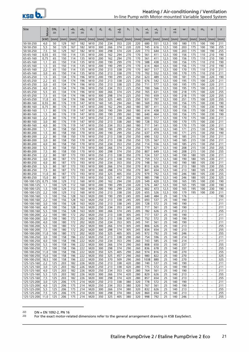
50-50-250 4,0 50 129 167 182 M10 250 234 353 220 220 680 551 12,5 100 180 175 100 190 21150-50-250 5,5 50 129 167 182 M10 300 266 374 220 220 745 616 12,5 100 203 175 100 190 25550-50-250 7,5 50 129 167 182 M10 300 298 374 220 220 773 644 12,5 100 203 175 100 190 25565-65-160 0,55 65 150 114 135 M10 200 162 294 270 170 561 411 12,5 100 156 175 110 210 19065-65-160 0,75 65 150 114 135 M10 200 162 294 270 170 561 411 12,5 100 156 175 110 210 19065-65-160 1,1 65 150 114 135 M10 200 190 299 270 170 588 438 12,5 100 156 175 110 210 19065-65-160 1,5 65 150 114 135 M10 200 190 299 270 170 614 464 12,5 100 156 175 110 210 19065-65-160 2,2 65 150 114 135 M10 250 213 338 270 170 667 517 12,5 100 170 175 110 210 21165-65-160 3,0 65 150 114 135 M10 250 213 338 270 170 702 552 12,5 100 170 175 110 210 21165-65-250 1,5 65 134 174 196 M10 200 190 299 225 250 623 489 12,5 100 181 175 100 220 19065-65-250 2,2 65 134 174 196 M10 250 213 338 225 250 676 542 12,5 100 195 175 100 220 21165-65-250 3,0 65 134 174 196 M10 250 213 338 225 250 711 577 12,5 100 195 175 100 220 21165-65-250 4,0 65 134 174 196 M10 250 234 353 225 250 700 566 12,5 100 195 175 100 220 21165-65-250 5,5 65 134 174 196 M10 300 266 374 225 250 765 631 12,5 100 218 175 100 220 25565-65-250 7,5 65 134 174 196 M10 300 298 374 225 250 793 659 12,5 100 218 175 100 220 25565-65-250 11,0 65 134 174 196 M10 350 325 405 225 250 931 797 12,5 100 251 175 100 220 25580-80-160 0,55 80 176 119 147 M10 160 145 294 260 180 569 393 12,5 100 156 175 100 230 19080-80-160 0,75 80 176 119 147 M10 200 162 294 260 180 587 411 12,5 100 156 175 100 230 19080-80-160 1,1 80 176 119 147 M10 200 190 299 260 180 614 438 12,5 100 156 175 100 230 19080-80-160 1,5 80 176 119 147 M10 200 190 299 260 180 640 464 12,5 100 156 175 100 230 19080-80-160 2,2 80 176 119 147 M10 250 213 338 260 180 693 517 12,5 100 170 175 100 230 21180-80-160 3,0 80 176 119 147 M10 250 213 338 260 180 728 552 12,5 100 170 175 100 230 21180-80-160 4,0 80 176 119 147 M10 250 234 353 260 180 717 541 12,5 100 170 175 100 230 21180-80-200 1,1 80 158 150 170 M10 200 190 299 250 250 611 453 12,5 140 171 215 130 250 19080-80-200 1,5 80 158 150 170 M10 200 190 299 250 250 637 479 12,5 140 171 215 130 250 19080-80-200 2,2 80 158 150 170 M10 250 213 338 250 250 690 532 12,5 140 185 215 130 250 21180-80-200 3,0 80 158 150 170 M10 250 213 338 250 250 725 567 12,5 140 185 215 130 250 21180-80-200 4,0 80 158 150 170 M10 250 234 353 250 250 714 556 12,5 140 185 215 130 250 21180-80-200 5,5 80 158 150 170 M10 300 266 374 250 250 779 621 12,5 140 208 215 130 250 25580-80-200 7,5 80 158 150 170 M10 300 298 374 250 250 807 649 12,5 140 208 215 130 250 25580-80-250 2,2 80 187 173 193 M10 250 213 338 350 270 724 537 12,5 140 190 180 105 230 21180-80-250 3,0 80 187 173 193 M10 250 213 338 350 270 759 572 12,5 140 190 180 105 230 21180-80-250 4,0 80 187 173 193 M10 250 234 353 350 270 748 561 12,5 140 190 180 105 230 21180-80-250 5,5 80 187 173 193 M10 300 266 374 350 270 813 626 12,5 140 213 180 105 230 25580-80-250 7,5 80 187 173 193 M10 300 298 374 350 270 841 654 12,5 140 213 180 105 230 25580-80-250 11,0 80 187 173 193 M10 350 325 405 350 270 979 792 12,5 140 246 180 105 230 25580-80-250 15,0 80 187 173 193 M10 350 325 457 350 270 985 798 12,5 140 246 180 105 230 325100-100-125 0,75 100 129 112 160 M10 200 162 294 230 220 549 420 12,5 100 165 195 100 230 190100-100-125 1,1 100 129 112 160 M10 200 190 299 230 220 576 447 12,5 100 165 195 100 230 190100-100-125 1,5 100 129 112 160 M10 200 190 299 230 220 602 473 12,5 100 165 195 100 230 190100-100-125 2,2 100 129 112 160 M10 250 213 338 230 220 655 526 12,5 100 179 195 100 230 211100-100-160 1,5 100 156 128 163 M20 200 190 299 245 205 640 484 25 140 176 - - - 190100-100-160 2,2 100 156 128 163 M20 250 213 338 245 205 693 537 25 140 190 - - - 211100-100-160 3,0 100 156 128 163 M20 250 213 338 245 205 728 572 25 140 190 - - - 211100-100-160 4,0 100 156 128 163 M20 250 234 353 245 205 717 561 25 140 190 - - - 211100-100-160 5,5 100 156 128 163 M20 300 266 374 245 205 782 626 25 140 213 - - - 255100-100-200 2,2 100 180 172 202 M20 250 213 338 305 245 717 537 25 140 190 - - - 211100-100-200 3,0 100 180 172 202 M20 250 213 338 305 245 752 572 25 140 190 - - - 211100-100-200 4,0 100 180 172 202 M20 250 234 353 305 245 741 561 25 140 190 - - - 211100-100-200 5,5 100 180 172 202 M20 300 266 374 305 245 806 626 25 140 213 - - - 255100-100-200 7,5 100 180 172 202 M20 300 298 374 305 245 834 654 25 140 213 - - - 255100-100-200 11,0 100 180 172 202 M20 350 325 405 305 245 972 792 25 140 246 - - - 255100-100-250 3,0 100 158 196 222 M20 250 213 338 290 260 754 596 25 140 214 - - - 211100-100-250 4,0 100 158 196 222 M20 250 234 353 290 260 743 585 25 140 214 - - - 211100-100-250 5,5 100 158 196 222 M20 300 266 374 290 260 808 650 25 140 237 - - - 255100-100-250 7,5 100 158 196 222 M20 300 298 374 290 260 836 678 25 140 237 - - - 255100-100-250 11,0 100 158 196 222 M20 350 325 405 290 260 974 816 25 140 270 - - - 255100-100-250 15,0 100 158 196 222 M20 350 325 457 290 260 980 822 25 140 270 - - - 325100-100-250 18,5 100 158 196 222 M20 350 370 509 290 260 1038 880 25 140 270 - - - 325125-125-160 2,2 125 203 182 226 M20 250 213 338 420 280 740 537 25 140 190 - - - 211125-125-160 3,0 125 203 182 226 M20 250 213 338 420 280 775 572 25 140 190 - - - 211125-125-160 4,0 125 203 182 226 M20 250 234 353 420 280 764 561 25 140 190 - - - 211125-125-160 5,5 125 203 182 226 M20 300 266 374 420 280 829 626 25 140 213 - - - 255125-125-160 7,5 125 203 182 226 M20 300 298 374 420 280 857 654 25 140 213 - - - 255125-125-200 3,0 125 206 175 214 M20 250 213 338 380 320 778 572 25 140 190 - - - 211125-125-200 4,0 125 206 175 214 M20 250 234 353 380 320 767 561 25 140 190 - - - 211125-125-200 5,5 125 206 175 214 M20 300 266 374 380 320 832 626 25 140 213 - - - 255125-125-200 7,5 125 206 175 214 M20 300 298 374 380 320 860 654 25 140 213 - - - 255125-125-200 11,0 125 206 175 214 M20 350 325 405 380 320 998 792 25 140 246 - - - 255
22) DN = EN 1092-2, PN 1623) For the exact motor-related dimensions refer to the general arrangement drawing in KSB EasySelect.
Heating / Air-conditioning / VentilationIn-line Pump with Motor-mounted Variable Speed System
Etaline PumpDrive 2 / Etaline PumpDrive 2 Eco 21
Size
Mo
tor DN1
22)
a ≈b1
23)
≈b2
23)
d1 d2 d3 ≈p23)
h1 h2 ≈I1
23)
≈I2
23)
t ≈x23)
w m1 m2 o z
[kW] [mm] [mm] [mm] [mm] [mm] [mm] [mm] [mm] [mm] [mm] [mm] [mm] [mm] [mm] [mm] [mm] [mm] [mm] [mm]
125-125-200 15,0 125 206 175 214 M20 350 325 457 380 320 1004 798 25 140 246 - - - 325125-125-250 5,5 125 210 188 219 M20 300 266 374 380 320 836 626 25 140 213 - - - 255125-125-250 7,5 125 210 188 219 M20 300 298 374 380 320 864 654 25 140 213 - - - 255125-125-250 11,0 125 210 188 219 M20 350 325 405 380 320 1002 792 25 140 246 - - - 255125-125-250 15,0 125 210 188 219 M20 350 325 457 380 320 1008 798 25 140 246 - - - 325125-125-250 18,5 125 210 188 219 M20 350 370 509 380 320 1066 856 25 140 246 - - - 325125-125-250 22,0 125 210 188 219 M20 350 370 509 380 320 1066 856 25 140 246 - - - 325150-150-200 5,5 150 230 187 240 M20 300 266 374 385 315 856 626 25 140 213 - - - 255150-150-200 7,5 150 230 187 240 M20 300 298 374 385 315 884 654 25 140 213 - - - 255150-150-200 11,0 150 230 187 240 M20 350 325 405 385 315 1022 792 25 140 246 - - - 255150-150-200 15,0 150 230 187 240 M20 350 325 457 385 315 1028 798 25 140 246 - - - 325150-150-200 18,5 150 230 187 240 M20 350 370 509 385 315 1086 856 25 140 246 - - - 325150-150-250 7,5 150 222 226 275 M20 300 298 374 370 330 891 669 25 140 228 - - - 255150-150-250 11,0 150 222 226 275 M20 350 325 405 370 330 1029 807 25 140 261 - - - 255150-150-250 15,0 150 222 226 275 M20 350 325 457 370 330 1035 813 25 140 261 - - - 325150-150-250 18,5 150 222 226 275 M20 350 370 509 370 330 1093 871 25 140 261 - - - 325150-150-250 22,0 150 222 226 275 M20 350 370 509 370 330 1093 871 25 140 261 - - - 325150-150-250 30,0 150 222 226 275 M20 400 422 558 370 330 1152 930 25 140 261 - - - 325150-150-250 37,0 150 222 226 275 M20 450 460 597 370 330 1209 987 25 140 292 - - - 425200-200-250 11,0 200 222 233 303 M20 350 325 405 400 400 1067 845 25 140 299 - - - 255200-200-250 15,0 200 222 233 303 M20 350 325 457 400 400 1073 851 25 140 299 - - - 325200-200-250 18,5 200 222 233 303 M20 350 370 509 400 400 1131 909 25 140 299 - - - 325200-200-250 22,0 200 222 233 303 M20 350 370 509 400 400 1131 909 25 140 299 - - - 325200-200-250 30,0 200 222 233 303 M20 400 422 558 400 400 1190 968 25 140 299 - - - 325200-200-250 37,0 200 222 233 303 M20 450 460 597 400 400 1247 1025 25 140 330 - - - 425200-200-250 45,0 200 222 233 303 M20 450 468 597 400 400 1277 1055 25 140 330 - - - 425200-200-315 22,0 200 255 259 318 M20 350 370 509 490 410 1141 886 25 140 276 - - - 325200-200-315 30,0 200 255 259 318 M20 400 422 558 490 410 1200 945 25 140 276 - - - 325200-200-315 37,0 200 255 259 318 M20 450 460 597 490 410 1257 1002 25 140 307 - - - 425200-200-315 45,0 200 255 259 318 M20 450 468 597 490 410 1287 1032 25 140 307 - - - 425
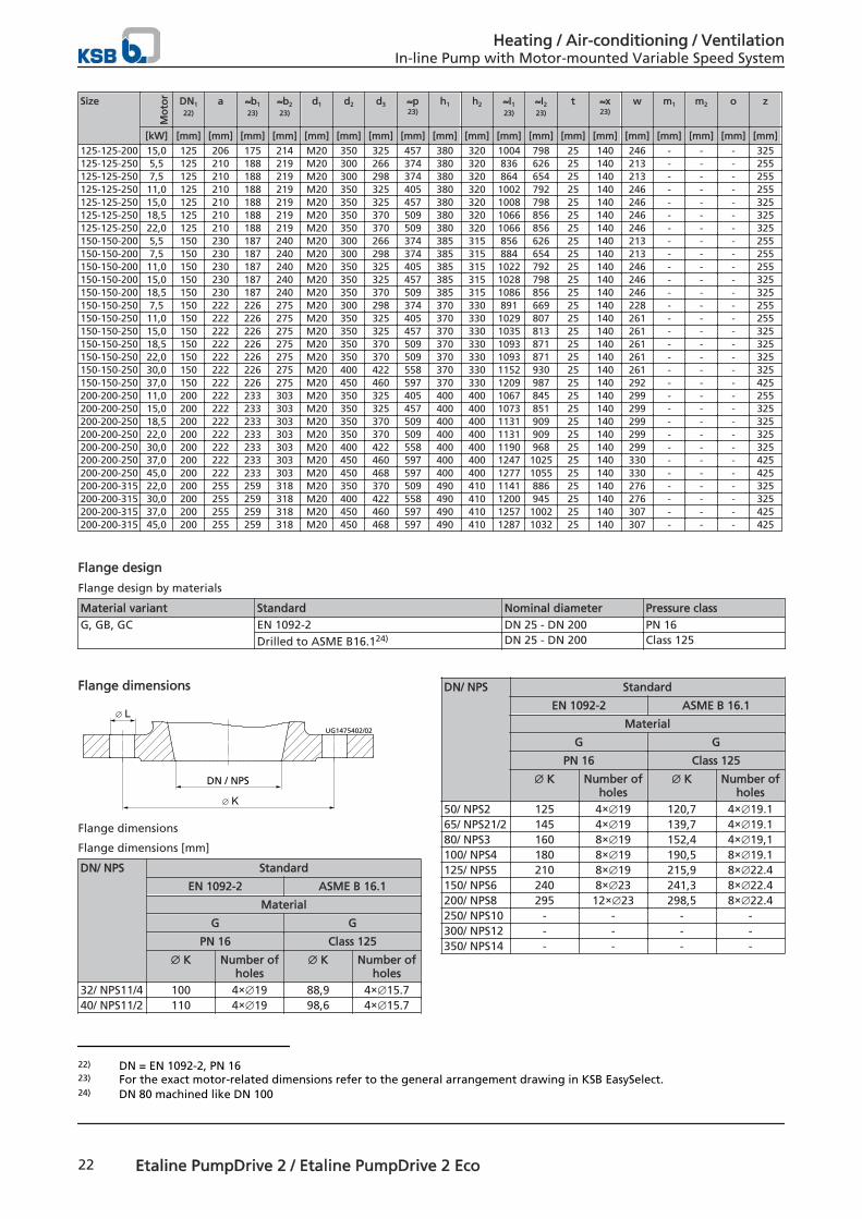
Flange design
Flange design by materials
Material variant Standard Nominal diameter Pressure classG, GB, GC EN 1092-2 DN 25 - DN 200 PN 16
Drilled to ASME B16.124) DN 25 - DN 200 Class 125
Flange dimensions
∅ L
∅ K
DN / NPS
UG1475402/02
Flange dimensions
Flange dimensions [mm]
DN/ NPS Standard
EN 1092-2 ASME B 16.1
Material
G G
PN 16 Class 125
∅ K Number ofholes
∅ K Number ofholes
32/ NPS11/4 100 4×∅19 88,9 4×∅15.740/ NPS11/2 110 4×∅19 98,6 4×∅15.7
DN/ NPS Standard
EN 1092-2 ASME B 16.1
Material
G G
PN 16 Class 125
∅ K Number ofholes
∅ K Number ofholes
50/ NPS2 125 4×∅19 120,7 4×∅19.165/ NPS21/2 145 4×∅19 139,7 4×∅19.180/ NPS3 160 8×∅19 152,4 4×∅19,1100/ NPS4 180 8×∅19 190,5 8×∅19.1125/ NPS5 210 8×∅19 215,9 8×∅22.4150/ NPS6 240 8×∅23 241,3 8×∅22.4200/ NPS8 295 12×∅23 298,5 8×∅22.4250/ NPS10 - - - -300/ NPS12 - - - -350/ NPS14 - - - -
22) DN = EN 1092-2, PN 1623) For the exact motor-related dimensions refer to the general arrangement drawing in KSB EasySelect.24) DN 80 machined like DN 100
Heating / Air-conditioning / VentilationIn-line Pump with Motor-mounted Variable Speed System
22 Etaline PumpDrive 2 / Etaline PumpDrive 2 Eco
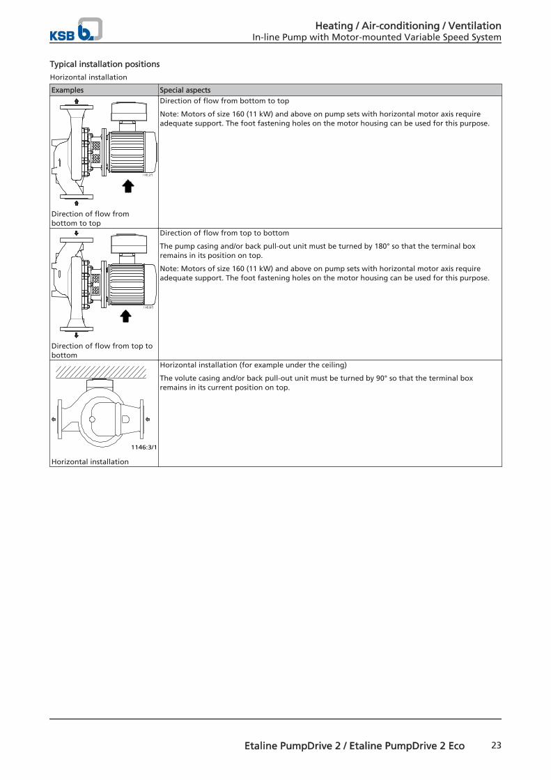
Typical installation positions
Horizontal installation
Examples Special aspects
Direction of flow frombottom to top
Direction of flow from bottom to top
Note: Motors of size 160 (11 kW) and above on pump sets with horizontal motor axis requireadequate support. The foot fastening holes on the motor housing can be used for this purpose.
Direction of flow from top tobottom
Direction of flow from top to bottom
The pump casing and/or back pull-out unit must be turned by 180° so that the terminal boxremains in its position on top.
Note: Motors of size 160 (11 kW) and above on pump sets with horizontal motor axis requireadequate support. The foot fastening holes on the motor housing can be used for this purpose.
1146:3/1
Horizontal installation
Horizontal installation (for example under the ceiling)
The volute casing and/or back pull-out unit must be turned by 90° so that the terminal boxremains in its current position on top.
Heating / Air-conditioning / VentilationIn-line Pump with Motor-mounted Variable Speed System
Etaline PumpDrive 2 / Etaline PumpDrive 2 Eco 23
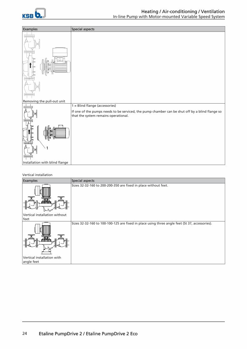
Examples Special aspects
Removing the pull-out unit
1
Installation with blind flange
1 = Blind flange (accessories)
If one of the pumps needs to be serviced, the pump chamber can be shut off by a blind flange sothat the system remains operational.
Vertical installation
Examples Special aspects
Vertical installation withoutfeet
Sizes 32-32-160 to 200-200-350 are fixed in place without feet.
Vertical installation withangle feet
Sizes 32-32-160 to 100-100-125 are fixed in place using three angle feet (St 37, accessories).
Heating / Air-conditioning / VentilationIn-line Pump with Motor-mounted Variable Speed System
24 Etaline PumpDrive 2 / Etaline PumpDrive 2 Eco
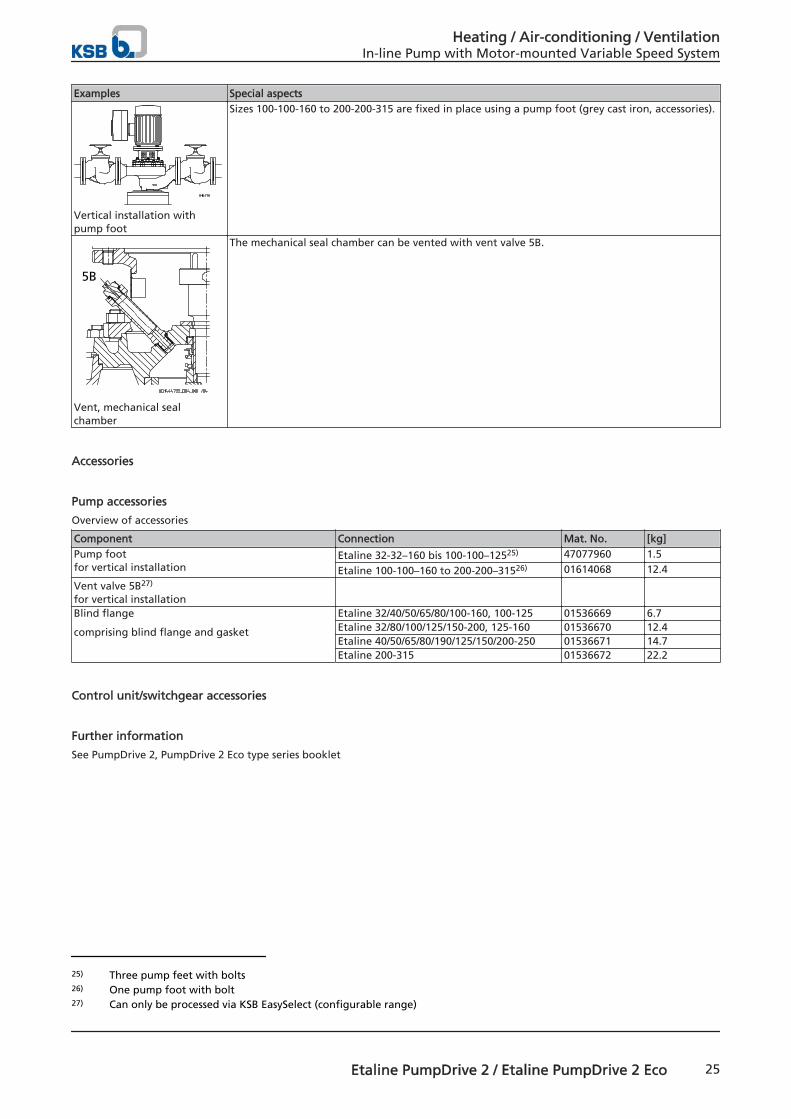
Examples Special aspects
Vertical installation withpump foot
Sizes 100-100-160 to 200-200-315 are fixed in place using a pump foot (grey cast iron, accessories).
5B
Vent, mechanical sealchamber
The mechanical seal chamber can be vented with vent valve 5B.
Accessories
Pump accessories
Overview of accessories
Component Connection Mat. No. [kg]Pump footfor vertical installation
Etaline 32-32–160 bis 100-100–12525) 47077960 1.5
Etaline 100-100–160 to 200-200–31526) 01614068 12.4
Vent valve 5B27)
for vertical installation
Blind flange
comprising blind flange and gasket
Etaline 32/40/50/65/80/100-160, 100-125 01536669 6.7Etaline 32/80/100/125/150-200, 125-160 01536670 12.4Etaline 40/50/65/80/190/125/150/200-250 01536671 14.7Etaline 200-315 01536672 22.2
Control unit/switchgear accessories
Further information
See PumpDrive 2, PumpDrive 2 Eco type series booklet
25) Three pump feet with bolts26) One pump foot with bolt27) Can only be processed via KSB EasySelect (configurable range)
Heating / Air-conditioning / VentilationIn-line Pump with Motor-mounted Variable Speed System
Etaline PumpDrive 2 / Etaline PumpDrive 2 Eco 25
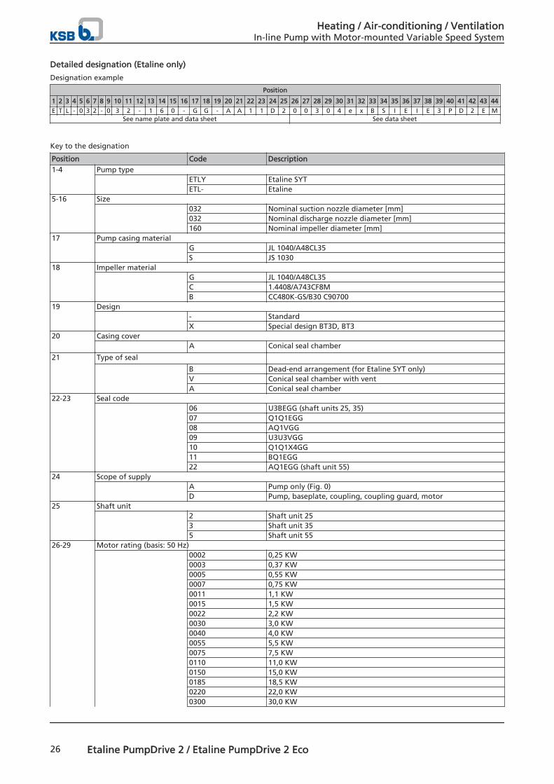
Detailed designation (Etaline only)
Designation example
Position
1 2 3 4 5 6 7 8 9 10 11 12 13 14 15 16 17 18 19 20 21 22 23 24 25 26 27 28 29 30 31 32 33 34 35 36 37 38 39 40 41 42 43 44
E T L - 0 3 2 - 0 3 2 - 1 6 0 - G G - A A 1 1 D 2 0 0 3 0 4 e x B S I E I E 3 P D 2 E MSee name plate and data sheet See data sheet
Key to the designation
Position Code Description1-4 Pump type
ETLY Etaline SYTETL- Etaline
5-16 Size 032 Nominal suction nozzle diameter [mm]
032 Nominal discharge nozzle diameter [mm]160 Nominal impeller diameter [mm]
17 Pump casing material G JL 1040/A48CL35
S JS 103018 Impeller material
G JL 1040/A48CL35C 1.4408/A743CF8MB CC480K-GS/B30 C90700
19 Design - Standard
X Special design BT3D, BT320 Casing cover
A Conical seal chamber
21 Type of seal B Dead-end arrangement (for Etaline SYT only)
V Conical seal chamber with ventA Conical seal chamber
22-23 Seal code 06 U3BEGG (shaft units 25, 35)
07 Q1Q1EGG08 AQ1VGG09 U3U3VGG10 Q1Q1X4GG11 BQ1EGG22 AQ1EGG (shaft unit 55)
24 Scope of supply A Pump only (Fig. 0)
D Pump, baseplate, coupling, coupling guard, motor25 Shaft unit
2 Shaft unit 253 Shaft unit 355 Shaft unit 55
26-29 Motor rating (basis: 50 Hz) 0002 0,25 KW
0003 0,37 KW0005 0,55 KW0007 0,75 KW0011 1,1 KW0015 1,5 KW0022 2,2 KW0030 3,0 KW0040 4,0 KW0055 5,5 KW0075 7,5 KW0110 11,0 KW0150 15,0 KW0185 18,5 KW0220 22,0 KW0300 30,0 KW
Heating / Air-conditioning / VentilationIn-line Pump with Motor-mounted Variable Speed System
26 Etaline PumpDrive 2 / Etaline PumpDrive 2 Eco
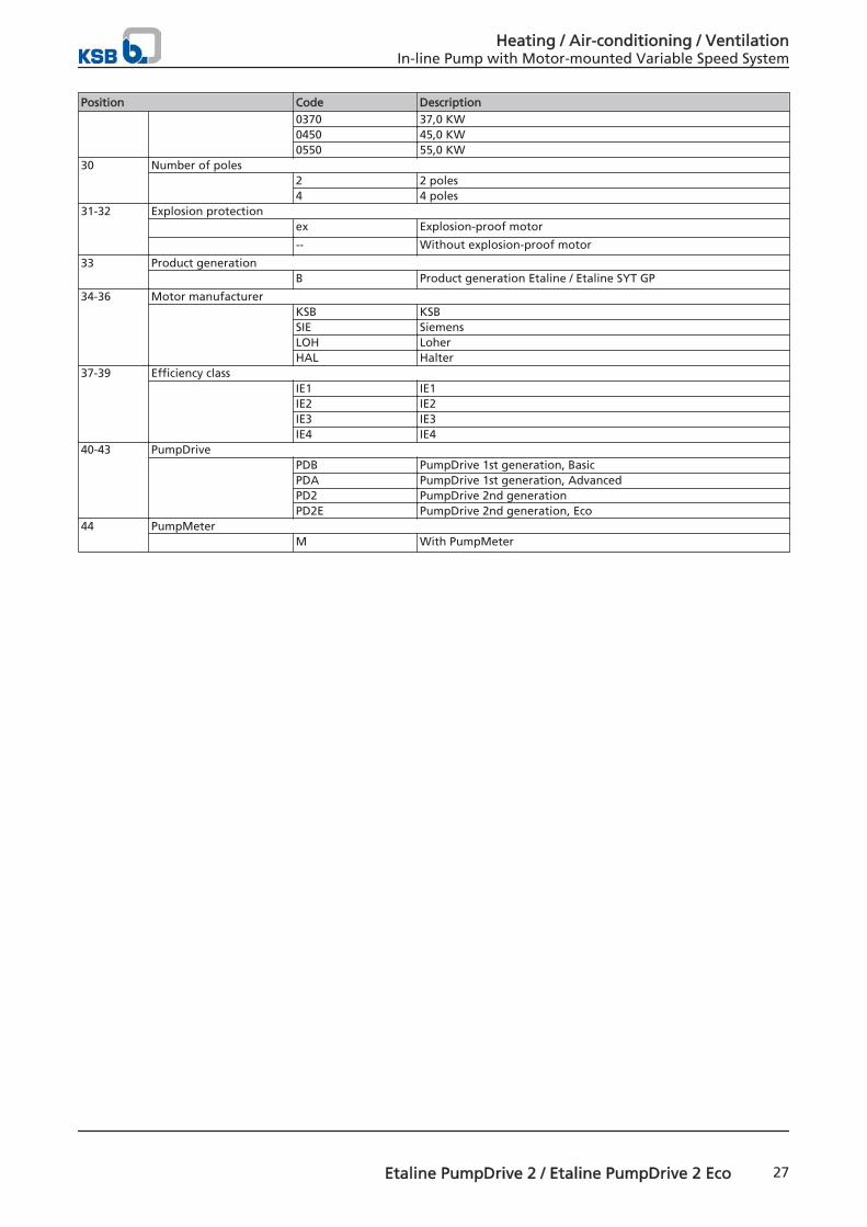
Position Code Description0370 37,0 KW0450 45,0 KW0550 55,0 KW
30 Number of poles 2 2 poles
4 4 poles31-32 Explosion protection
ex Explosion-proof motor
-- Without explosion-proof motor
33 Product generation B Product generation Etaline / Etaline SYT GP
34-36 Motor manufacturer KSB KSB
SIE SiemensLOH LoherHAL Halter
37-39 Efficiency class IE1 IE1
IE2 IE2IE3 IE3IE4 IE4
40-43 PumpDrive PDB PumpDrive 1st generation, Basic
PDA PumpDrive 1st generation, AdvancedPD2 PumpDrive 2nd generationPD2E PumpDrive 2nd generation, Eco
44 PumpMeter M With PumpMeter
Heating / Air-conditioning / VentilationIn-line Pump with Motor-mounted Variable Speed System
Etaline PumpDrive 2 / Etaline PumpDrive 2 Eco 27
PumpMeter
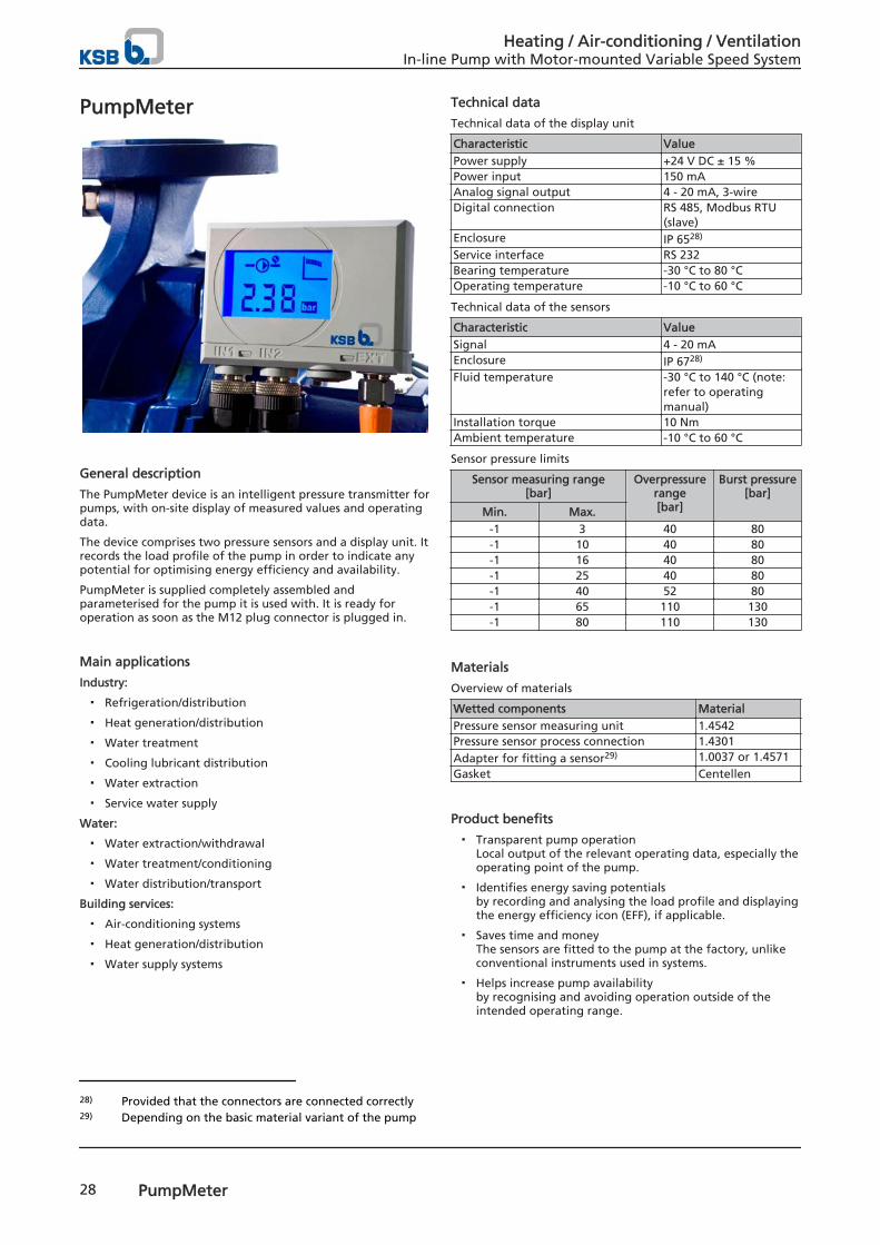
General description
The PumpMeter device is an intelligent pressure transmitter forpumps, with on-site display of measured values and operatingdata.
The device comprises two pressure sensors and a display unit. Itrecords the load profile of the pump in order to indicate anypotential for optimising energy efficiency and availability.
PumpMeter is supplied completely assembled andparameterised for the pump it is used with. It is ready foroperation as soon as the M12 plug connector is plugged in.
Main applications
Industry:
▪ Refrigeration/distribution
▪ Heat generation/distribution
▪ Water treatment
▪ Cooling lubricant distribution
▪ Water extraction
▪ Service water supply
Water:
▪ Water extraction/withdrawal
▪ Water treatment/conditioning
▪ Water distribution/transport
Building services:
▪ Air-conditioning systems
▪ Heat generation/distribution
▪ Water supply systems
Technical data
Technical data of the display unit
Characteristic ValuePower supply +24 V DC ± 15 %Power input 150 mAAnalog signal output 4 - 20 mA, 3-wireDigital connection RS 485, Modbus RTU
(slave)Enclosure IP 6528)
Service interface RS 232Bearing temperature -30 °C to 80 °COperating temperature -10 °C to 60 °C
Technical data of the sensors
Characteristic ValueSignal 4 - 20 mAEnclosure IP 6728)
Fluid temperature -30 °C to 140 °C (note:refer to operatingmanual)
Installation torque 10 NmAmbient temperature -10 °C to 60 °C
Sensor pressure limits
Sensor measuring range[bar]
Overpressurerange[bar]
Burst pressure[bar]
Min. Max.-1 3 40 80-1 10 40 80-1 16 40 80-1 25 40 80-1 40 52 80-1 65 110 130-1 80 110 130
Materials
Overview of materials
Wetted components MaterialPressure sensor measuring unit 1.4542Pressure sensor process connection 1.4301Adapter for fitting a sensor29) 1.0037 or 1.4571Gasket Centellen
Product benefits
▪ Transparent pump operationLocal output of the relevant operating data, especially theoperating point of the pump.
▪ Identifies energy saving potentialsby recording and analysing the load profile and displayingthe energy efficiency icon (EFF), if applicable.
▪ Saves time and moneyThe sensors are fitted to the pump at the factory, unlikeconventional instruments used in systems.
▪ Helps increase pump availabilityby recognising and avoiding operation outside of theintended operating range.
28) Provided that the connectors are connected correctly29) Depending on the basic material variant of the pump
Heating / Air-conditioning / VentilationIn-line Pump with Motor-mounted Variable Speed System
28 PumpMeter
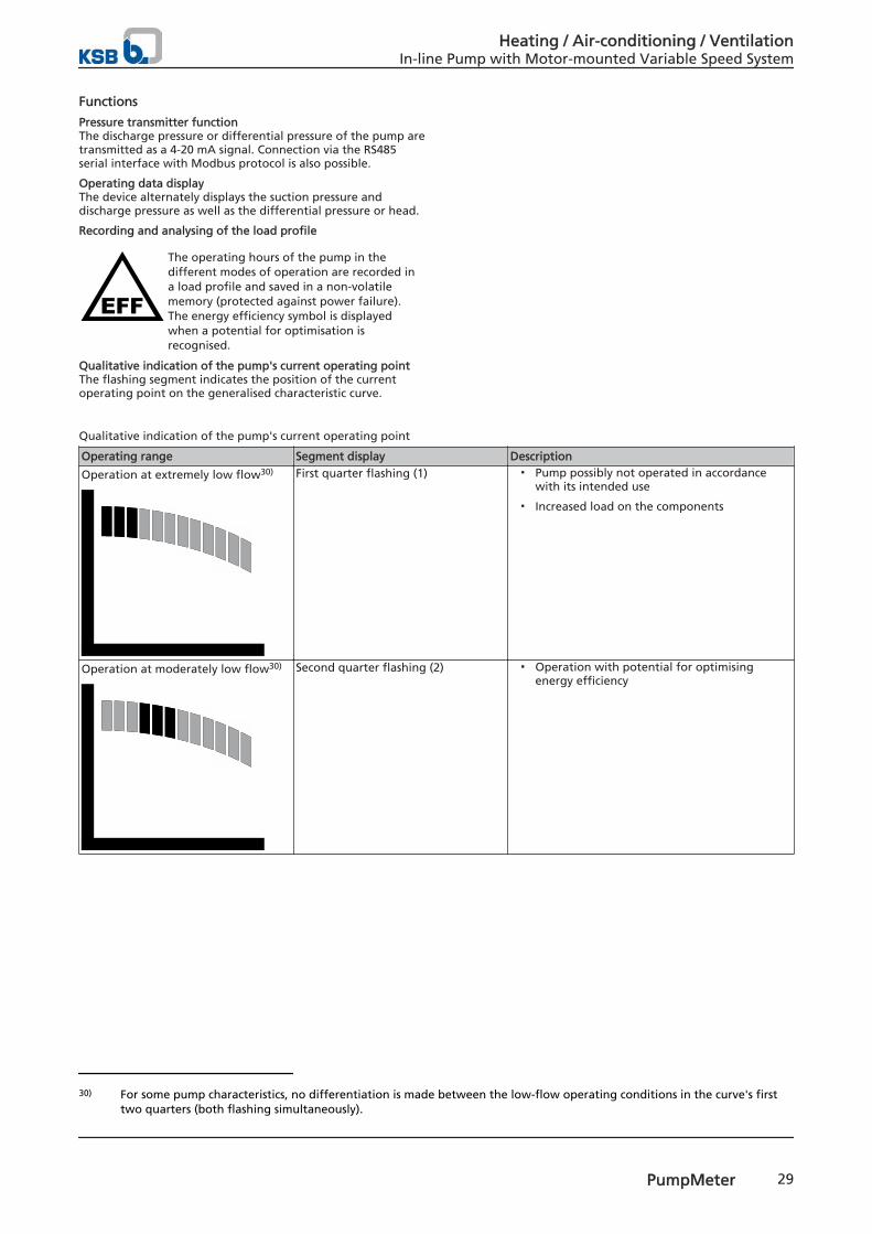
Functions
Pressure transmitter functionThe discharge pressure or differential pressure of the pump aretransmitted as a 4-20 mA signal. Connection via the RS485serial interface with Modbus protocol is also possible.
Operating data displayThe device alternately displays the suction pressure anddischarge pressure as well as the differential pressure or head.
Recording and analysing of the load profile
The operating hours of the pump in thedifferent modes of operation are recorded ina load profile and saved in a non-volatilememory (protected against power failure).The energy efficiency symbol is displayedwhen a potential for optimisation isrecognised.
Qualitative indication of the pump's current operating pointThe flashing segment indicates the position of the currentoperating point on the generalised characteristic curve.
Qualitative indication of the pump's current operating point
Operating range Segment display Description
Operation at extremely low flow30) First quarter flashing (1) ▪ Pump possibly not operated in accordancewith its intended use
▪ Increased load on the components
Operation at moderately low flow30) Second quarter flashing (2) ▪ Operation with potential for optimisingenergy efficiency
30) For some pump characteristics, no differentiation is made between the low-flow operating conditions in the curve's firsttwo quarters (both flashing simultaneously).
Heating / Air-conditioning / VentilationIn-line Pump with Motor-mounted Variable Speed System
PumpMeter 29
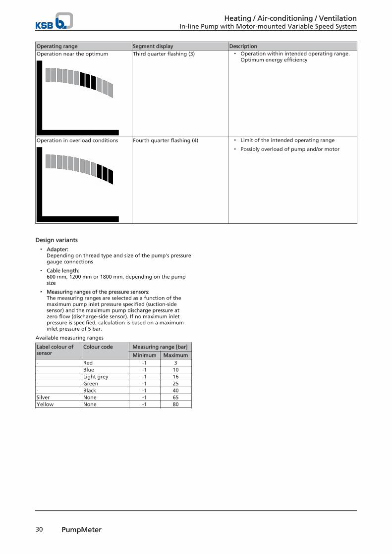
Operating range Segment display DescriptionOperation near the optimum Third quarter flashing (3) ▪ Operation within intended operating range.
Optimum energy efficiency
Operation in overload conditions Fourth quarter flashing (4) ▪ Limit of the intended operating range
▪ Possibly overload of pump and/or motor
Design variants
▪ Adapter:Depending on thread type and size of the pump's pressuregauge connections
▪ Cable length:600 mm, 1200 mm or 1800 mm, depending on the pumpsize
▪ Measuring ranges of the pressure sensors:The measuring ranges are selected as a function of themaximum pump inlet pressure specified (suction-sidesensor) and the maximum pump discharge pressure atzero flow (discharge-side sensor). If no maximum inletpressure is specified, calculation is based on a maximuminlet pressure of 5 bar.
Available measuring ranges
Label colour ofsensor
Colour code Measuring range [bar]
Minimum Maximum- Red -1 3- Blue -1 10- Light grey -1 16- Green -1 25- Black -1 40Silver None -1 65Yellow None -1 80
Heating / Air-conditioning / VentilationIn-line Pump with Motor-mounted Variable Speed System
30 PumpMeter
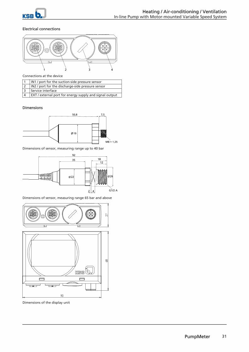
Electrical connections
1
1 2 3 4
2
34
1 2
34
Connections at the device
1 IN1 / port for the suction-side pressure sensor2 IN2 / port for the discharge-side pressure sensor3 Service interface4 EXT / external port for energy supply and signal output
Dimensions
50,8
M8 × 1,25
7,5
19
Dimensions of sensor, measuring range up to 40 bar
92
35
22
1812
42
26
G1/2 A
Dimensions of sensor, measuring range 65 bar and above
Dimensions of the display unit
Heating / Air-conditioning / VentilationIn-line Pump with Motor-mounted Variable Speed System
PumpMeter 31

1159
.52/
01-EN
27.1
0.20
14
KSB Aktiengesellschaft67225 Frankenthal • Johann-Klein-Str. 9 • 67227 Frankenthal (Germany)Tel. +49 6233 86-0 • Fax +49 6233 86-3401www.ksb.com