Embed Size (px)
Citation preview
[Fire Research 2017; 1:16] [page 7]
Buckling behavior of cold-formed steel columnsat both ambient temperatureand simulated fire conditionsHélder D. Craveiro, João Paulo C. Rodrigues, Luís M. LaímInstitute for Sustainability andInnovation in Structural Engineering,University of Coimbra, Coimbra, Portugal
Abstract
Cold-formed steel (CFS) profiles with a widerange of cross-section shapes are commonlyused in building construction industry.Nowadays several cross-sections can be builtusing the available standard single sections(C, U, Σ, etc.), namely open built-up and closedbuilt-up cross-sections. This paper reports anextensive experimental investigation on thebehavior of single and built-up cold-formedsteel columns at both ambient and simulatedfire conditions considering the effect ofrestraint to thermal elongation. The bucklingbehavior, ultimate loads and failure modes, ofdifferent types of CFS columns at both ambientand simulated fire conditions with restraint tothermal elongation, are presented and com-pared. Regarding the buckling tests at ambienttemperature it was observed that the use ofbuilt-up cross-sections ensures significantlyhigher values of buckling loads. Especially forthe built-up cross-sections the failure modeswere characterized by the interaction of indi-vidual buckling modes, namely flexural aboutthe minor axis, distortional and local buckling.Regarding the fire tests, it is clear that thesame levels of restraint used in the experi-mental investigation induce different rates inthe generated restraining forces due to ther-mal elongation of the columns. Another con-clusion that can be drawn from the results isthat by increasing the level of restraint to ther-mal elongation the failure of the columns iscontrolled by the generated restraining forces,whereas for lower levels of restraint the tem-perature plays a more important role. Hence,higher levels of imposed restraint to thermalelongation will lead to higher values of gener-ated restraining forces and eventually to lowervalues of critical temperature and time.
Introduction
There have been some significant develop-ments in cold-formed steel (CFS) structures
over the past few decades, mainly due toimproving technology of manufacture (higherquality steels, more complex section shapes,improved forming technology) and corrosionprotection. This leads to greater competitive-ness of this structural solution that has beentranslated into an increasing market sharethroughout the world. In the past few decades’researchers have been focused on thebehaviour of cold-formed steel structures.Regarding the behaviour of CFS columns,research has been mainly focused on open sec-tions, such as plain and lipped channels, chan-nels with simple and complex edge stiffeners,with and without holes, and angles.1-4 Morerecently built-up members have also beeninvestigated by some researchers. Built-upcross-sections present several advantageswhen compared with single sections. A built-up section can span more distance, present ahigher load bearing capacity and higher tor-sional stiffness.4 Also the use of built-up cross-sections can be a major economic advantagesince all manufacture process remains thesame.5 Usually this type of cross-sections isbuilt using self-drilling screws or seam weld.6
At ambient temperature some research con-cerning the ultimate load-carrying capacity ofbuilt-up closed CFS columns has been conduct-ed.7
However, so far, design methodologies pre-sented in current design codes are still poorespecially for built-up columns under fire situ-ation. Traditionally two design methods areused, the Effective Width Method (EWM) usedglobally and the Direct Strength Method(DSM)8 used in North America, Australia/NewZealand. The EN 1993-1-3:20069 only predictsthat the buckling resistance of a closed built-up cross-section should be determined usingthe buckling curve b in association with thebasic yield strength fyb, and buckling curve c inassociation with the average yield strength fya
provided that Aeff = Ag.Regarding fire design the methods present-
ed in the EN 1993-1-2:200510 for hot-rolled steelmembers are also applicable to cold-formedsteel members with class 4 cross-sections. Alsothe EN 1993-1-2:200510 for class 4 cross-sec-tions limits the critical temperature to 350ºC.Regarding the fire behaviour of cold-formedsteel columns considering the influence ofrestraint to thermal elongation the investiga-tions is still scarce. In a real building in case offire it is most likely that a column may be sub-jected to thermal elongation. Since that col-umn is restrained by the surrounding struc-ture this particular column will be subjected toadditional compressive forces that are gener-ated due to the fact that the free thermal elon-gation is restrained by the surrounding struc-ture. This phenomenon may lead to prematurefailure. Hence, it is clear that the effect of
restraint to thermal elongation in cold-formedsteel columns should be thoroughly studied.
To sum up, an extensive experimentalinvestigation on the buckling behaviour of CFScolumns at both ambient and simulated fireconditions was undertaken. Four cross-sectionshapes, two end-support conditions were test-ed in ambient temperature buckling tests. Inthe fire tests the same cross-section shapeswere tested as well as two levels of service load(30 and 50% Nb,Rd) and restraint to thermalelongation.
Materials and Methods
Test specimensAll specimens consisted of one or more CFS
profiles, namely plain channels (U) and lippedchannel (C) profiles (Figure 1). All profileswere fabricated with S280GD+Z structuralsteel, hot dip galvanized with zinc on eachside, and with yield strength of 280 MPa and anultimate tensile strength of 360 MPa. Usingthe single sections it was possible to combinethem to fabricate built-up cross-sections usingself-drilling screws Hilti S-6.3×19MD03Z. Thelength of all profiles was 2950 mm and the
Fire Research 2017; volume 1:16
Correspondence: Hélder D. Craveiro, Institute forSustainability and Innovation in StructuralEngineering, University of Coimbra, rua LuísReis Santos, 3030788 Coimbra, Portugal. Tel: +351.912168154 - Fax: +351.239797123. E-mail: [email protected]
Key words: Built-up; Cold-formed steel; Column;Buckling; Experimental.
Acknowledgements: the authors gratefullyacknowledge the Portuguese Foundation forScience and Technology-FCT (www.fct.mctes.pt)and the cold-formed steel profile maker Perfisa(www.perfisa.net) for their support under theframework of the research projectPTDC/ECM/116859/2010, as well as to the HumanPotential Operational Programme (POPH), theEuropean social fund and national strategic refer-ence framework (QREN). This work was also sup-ported by FCT, within ISISE, projectUID/ECI/04029/2013.
Received for publication: 17 April 2016.Accepted for publication: 15 November 2016.
This work is licensed under a Creative CommonsAttribution 4.0 License (by-nc 4.0).
©Copyright H.D. Craveiro et al., 2017Licensee PAGEPress, ItalyFire Research 2017; 1:16doi:10.4081/fire.2017.16
Non co
mmercial
use o
nly
[page 8] [Fire Research 2017; 1:16]
spacing of the fasteners along the length of thecolumn was 725 mm. In both bukling tests andfire tests each cross-section tested was instru-mented with strain gauges and thermocouples,respectively. In the buckling tests the straingauges were placed in several points of thecross-section at mid-height of each CFS col-umn tested. In the fire tests thermocoupleswere positioned in different points of thecross-section and in five different sectionsalong the length of the column.
Test set-up for buckling testsThe test set-up specifically designed for con-
ducting buckling tests on CFS columns is thor-oughly described in this section. With thisexperimental system it was attempted to simu-late both pin and fixed-ended conditions inorder to assess lower and upper bounds of thebuckling load of the tested CFS columns. Theexperimental test set-up comprised a 2D reac-tion steel frame (i), a concrete footing (ii), thedesigned end-support devices (iii), load cellused to measure the applied load (iv), thehydraulic jack (v) used to apply the load to theCFS column, the servo hydraulic central unitW+B NSPA700/DIG2000 (vi) and the data acqui-sition system TML TDS-530 (vii) (Figure 2).
Test set-up for fire tests withrestraint to thermal elongation
The experimental set-up comprised a twodimensional (2D) reaction steel frame (i inFigure 3a and b) and a three dimensional (3D)restraining steel frame adaptable for differentlevels of stiffness (ii in Figure 3a and b) inorder to simulate the axial and rotationalrestraint imposed by the surrounding struc-ture to a CFS column (vi) in fire. To achievethe desired levels of stiffness of the surround-ing structure, in order to provide axial androtational restraint (K1 to K4) to the thermalelongation of the CFS columns, two different3D restraining frames were used in the exper-imental tests. In order to confirm the levels ofstiffness, in addition to the experimental tests,some numerical simulations were carried out.Replacing the CFS column by a hydraulic jack aconstant load was applied to the restraining
frame and the respective vertical nodal (pointof intersection of the top beams of the 3Drestraining frame) displacement measured.The obtained values were also confirmed withthe values of the restraining forces and axialdisplacements registered in the fire resistancetests of CFS columns. The rotational stiffnessof both restraining frames (RF.1 and RF.2) wasdetermined through numerical simulationsusing the finite element software Abaqus.From calculations and for the restrainingframe with axial stiffness of 3 kN/mm a rota-tional stiffness of 9253 kN.m/rad and 2196
kN.m/rad was obtained. For the restrainingframe with an axial stiffness of 13 kN/mm arotational stiffness of 37237 kN.m/rad and12620 kN.m/rad was obtained, respectivelyabout the minor and major axis of the CFS col-umn.
The connections between the peripheralcolumns and the top beams of the restrainingframe were made with threaded rods. Ahydraulic jack, placed in the 2D reactionframe, was used to apply the serviceability load(iii in Figure 3a and b). The thermal actionwas applied by a vertical modular electric fur-
Article
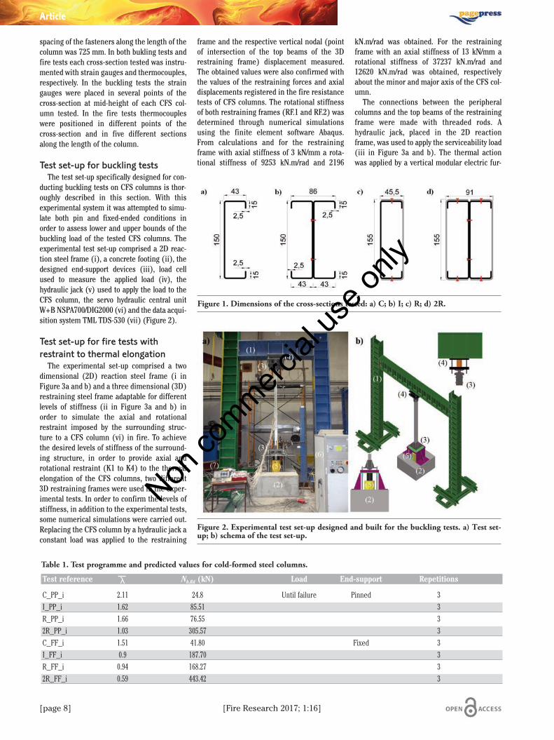
Table 1. Test programme and predicted values for cold-formed steel columns.
Test reference λ Nb,Rd (kN) Load End-support Repetitions
C_PP_i 2.11 24.8 Until failure Pinned 3I_PP_i 1.62 85.51 3R_PP_i 1.66 76.55 32R_PP_i 1.03 305.57 3C_FF_i 1.51 41.80 Fixed 3I_FF_i 0.9 187.70 3R_FF_i 0.94 168.27 32R_FF_i 0.59 443.42 3
Figure 1. Dimensions of the cross-sections tested: a) C; b) I; c) R; d) 2R.
Figure 2. Experimental test set-up designed and built for the buckling tests. a) Test set-up; b) schema of the test set-up.
Non co
mmercial
use o
nly
[Fire Research 2017; 1:16] [page 9]
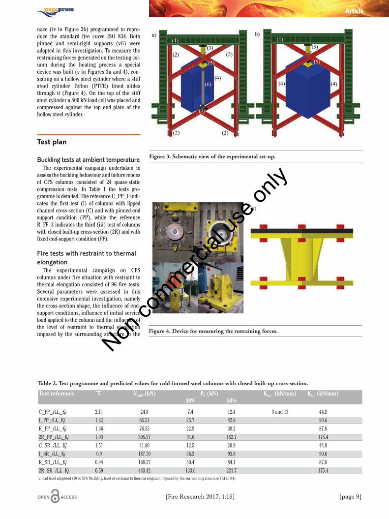
nace (iv in Figure 3b) programmed to repro-duce the standard fire curve ISO 834. Bothpinned and semi-rigid supports (vii) wereadopted in this investigation. To measure therestraining forces generated on the testing col-umn during the heating process a specialdevice was built (v in Figures 3a and 4), con-sisting on a hollow steel cylinder where a stiffsteel cylinder Teflon (PTFE) lined slidesthrough it (Figure 4). On the top of the stiffsteel cylinder a 500 kN load cell was placed andcompressed against the top end plate of thehollow steel cylinder.
Test plan
Buckling tests at ambient temperatureThe experimental campaign undertaken to
assess the buckling behaviour and failure modesof CFS columns consisted of 24 quase-staticcompression tests. In Table 1 the tests pro-gramme is detailed. The reference C_PP_1 indi-cates the first test (i) of columns with lippedchannel cross-section (C) and with pinned-endsupport condition (PP), while the referenceR_FF_3 indicates the third (iii) test of columnswith closed built-up cross-section (2R) and withfixed end-support condition (FF).
Fire tests with restraint to thermalelongation
The experimental campaign on CFScolumns under fire situation with restraint tothermal elongation consisted of 96 fire tests.Several parameters were assessed in thisextensive experimental investigation, namelythe cross-section shape, the influence of end-support conditions, influence of initial serviceload applied to the column and the influence ofthe level of restraint to thermal elongationimposed by the surrounding structure to the
Article
Table 2. Test programme and predicted values for cold-formed steel columns with closed built-up cross-section.
Test reference λ Nb,Rd (kN) P0 (kN) Ka,s (kN/mm) Ka,c (kN/mm) 30% 50%
C_PP_iLL_Kj 2.11 24.8 7.4 12.4 3 and 13 44.8I_PP_iLL_Kj 1.62 85.51 25.7 42.8 90.6R_PP_iLL_Kj 1.66 76.55 22.9 38.2 87.02R_PP_iLL_Kj 1.03 305.57 91.6 152.7 175.4C_SR_iLL_Kj 1.51 41.80 12.5 20.9 44.8I_SR_iLL_Kj 0.9 187.70 56.3 93.8 90.6R_SR_iLL_Kj 0.94 168.27 50.4 84.1 87.02R_SR_iLL_Kj 0.59 443.42 133.0 221.7 175.4i, load level adopteed (30 or 50% Nb,Rd); j, level of restraint to thermal elogation imposed by the surrounding structure (K1 to K4).
Figure 3. Schematic view of the experimental set-up.
Figure 4. Device for measuring the restraining forces.
Non co
mmercial
use o
nly
[page 10] [Fire Research 2017; 1:16]
CFS column. For each test condition three rep-etitions were conducted. For instance, lippedchannel columns were tested considering twoend-support conditions, two levels of serviceload and two levels of restraint to thermal elon-gation. Hence, 24 fire tests were undertakenfor columns with lipped channel cross-section.
The applied load (P0) corresponded to 30and 50% of the design buckling load at ambienttemperature (Nb,Rd). The design buckling loadswere determined according to the provisionspresented in EN 1993-1-1:2005,11 EN 1993-1-3:20069 and EN 1993-1-5:2006.12 The non-dimensional slenderness was determinedaccording the provisions presented in the EN1993-1-1:200511 for class 4 cross sections. Thelevel of axial restraint imposed to a CFS col-umn is defined as the ratio (eq. 1) between theaxial stiffness of the surrounding structure tothe CFS column (Ka,s) and the axial stiffness ofthe column (Ka,c) (eq. 1):
where . In Table 2, the refer-ence C_PP_30LL_K1-2, indicates the secondtest (2) of the column with lipped channel (C)cross-section tested with 3 kN/mm of axialstiffness of the surrounding structure (K1)and a 30% load level (30LL) for the pin-endedsupport condition (PP), while the referenceI_SR_50LL_K4-3 indicates the third test (3) ofthe column with built-up I (I) cross-sectionwith 13 kN/mm of axial stiffness and 37237and 12620 kN.m/rad of rotational stiffnessabout the minor and major axis of the CFS col-umn (K4), respectively and a 50% load level(50LL) for the semi-rigid support condition(SR).
Results and Discussion
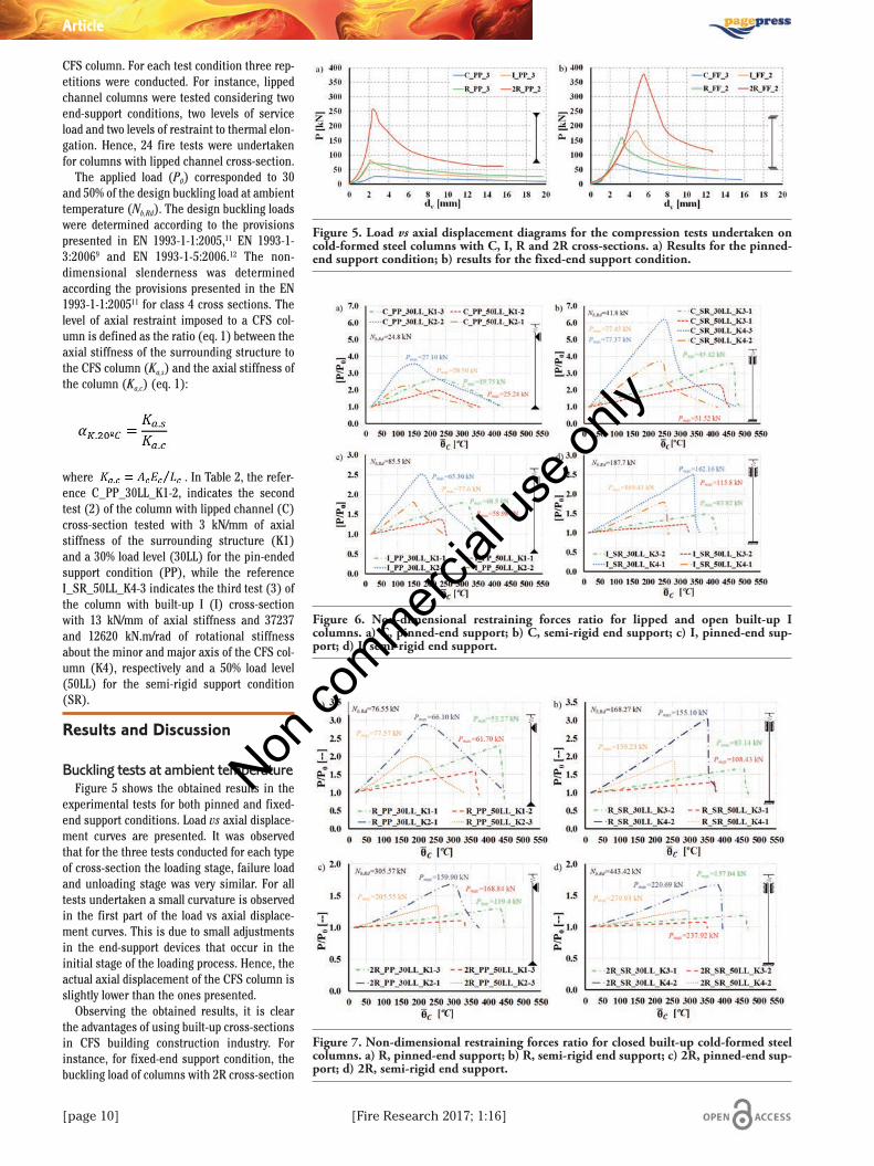
Buckling tests at ambient temperatureFigure 5 shows the obtained results in the
experimental tests for both pinned and fixed-end support conditions. Load vs axial displace-ment curves are presented. It was observedthat for the three tests conducted for each typeof cross-section the loading stage, failure loadand unloading stage was very similar. For alltests undertaken a small curvature is observedin the first part of the load vs axial displace-ment curves. This is due to small adjustmentsin the end-support devices that occur in theinitial stage of the loading process. Hence, theactual axial displacement of the CFS column isslightly lower than the ones presented.
Observing the obtained results, it is clearthe advantages of using built-up cross-sectionsin CFS building construction industry. Forinstance, for fixed-end support condition, thebuckling load of columns with 2R cross-section
Article
Figure 5. Load vs axial displacement diagrams for the compression tests undertaken oncold-formed steel columns with C, I, R and 2R cross-sections. a) Results for the pinned-end support condition; b) results for the fixed-end support condition.
Figure 6. Non-dimensional restraining forces ratio for lipped and open built-up Icolumns. a) C, pinned-end support; b) C, semi-rigid end support; c) I, pinned-end sup-port; d) I, semi-rigid end support.
Figure 7. Non-dimensional restraining forces ratio for closed built-up cold-formed steelcolumns. a) R, pinned-end support; b) R, semi-rigid end support; c) 2R, pinned-end sup-port; d) 2R, semi-rigid end support.
Non co
mmercial
use o
nly
[Fire Research 2017; 1:16] [page 11]
was 5.6 times higher than the buckling load ofcolumns with lipped channels, 2.01 times high-er than the buckling load of columns with openbuilt-up I cross-section and 2.51 times higherthan the buckling load of columns with closedbuilt-up R cross-section, for the pinned-endsupport condition. Comparing both experimen-tal results with the design buckling load (Nb,Rd)determined according the EN 1993-1-3:20069
some relevant differences were observed. Forinstance, it seems that the design-bucklingload is too conservative for fixed-ended lippedchannel columns. Also it was observed thatincreasing the number of profiles it seems thatthe design buckling predictions becomeunconservative, as it can be observed forcolumns with 2R cross-section.
Fire tests with restraint to thermalelongation
The evolution of restraining forces is anon-dimensional P/P0 ratio presented as afunctionof the mean temperature of the columnfor the different tested conditions. The meantemperature represents the integral of theweighted mean temperature calculated ineach one of the instrumented sections alongthe length of the column. In these graphs it ispossible to observe the expected behaviour ofa column in a real structure as the effect of asurrounding structure was simulated with the3D restraining frames. Each tested columnwas loaded with a compressive serviceabilityload (30 and 50% Nb,Rd) that was kept constantthroughout the entire fire test. Due to thethermal action and since the column was axi-ally restrained the axial compression force(restraining forces) on the column started toincrease whereas the mechanical propertiesof CFS degraded with the temperatureincrease. After reaching a maximum (Pmax)the restraining forces (P) started to decreasereaching the initial service load applied (P0)to the CFS column. This point defines the crit-ical time (tcr) and temperature (θcr) as thefailure criteria in these experimental tests. InFigures 6 and 7 some results concerning theevolution of the restraining forces are pre-sented. Observing the obtained results theinfluence of the initial applied load is clear.Increasing the serviceability load from 30 to50% Nb,Rd critical temperatures and criticaltimes decreased for all tested cross-sections.Analysing the results taking into considera-tion the imposed levels of restraint to thermalelongation to the CFS column it was observedthat, generally, increasing the level of theimposed restraint to thermal elongation thecritical times and temperatures decreased.
It was clearly observed for every tested con-ditions that increasing the level of axialrestraint to thermal elongation from 3 to 13kN/mm the generated restraining forces
increase significantly and the maximumvalue was reached for much lower mean tem-peratures. For example, for the 2R cross-sec-tion and considering a 30% initial load leveland semi-rigid end-support condition,increasing the level of restraint lead, on aver-age, to a reduction of the peak temperature of91ºC. Also, it was observed that the magni-tude of the generated restraining forces washigher for the lower initial load level. Forinstance, the average magnitude of the gen-erated restraining forces (P-P0) obtained forthe R_SR_30LL_K3 tests was about 32.78 kNwhereas for the R_SR_50LL_K3 tests was25.33 kN.
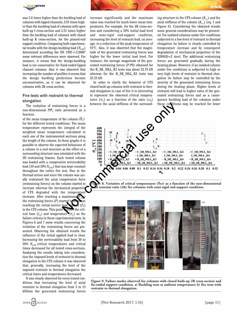
In order to clarify the behavior of CFSclosed built-up columns with restraint to ther-mal elongation in case of fire it is interestingto represent the observed critical tempera-tures (θcr) as a function of the ratio (αk)between the axial stiffness of the surround-
ing structure to the CFS column (Ka,s) and theaxial stiffness of the column (Ka,c) (eq. 1 andFigure 8). Considering the obtained resultssome general considerations may be present-ed. For isolated columns under fire conditionssubjected to a low level of restraint to thermalelongation its failure is clearly controlled bytemperature increase and by consequentdegradation of mechanical properties of theS280GD+Z steel. The additional restrainingforces are generated gradually during theheating phase. However, if an isolated columnunder fire conditions is subjected to high orvery high levels of restraint to thermal elon-gation its failure may be controlled by theseverity of the generated restraining forcesduring the heating phase. Higher levels ofrestraint will lead to higher rates of the gen-erated restraining forces and as a conse-quence buckling load of the columns underthese conditions may be reached for lower
Article
Figure 8. Variation of critical temperatures (θcr) as a function of the non-dimensionalaxial restraint ratio (αk) for columns with semi-rigid end-support condition.
Figure 9. Failure modes observed for columns with closed built-up 2R cross-section andfix-ended support condition. a) Buckling tests at ambient temperature; b) fire tests withrestraint to thermal elongation.
Non co
mmercial
use o
nly

[page 12] [Fire Research 2017; 1:16]
temperatures.
Failure modesGenerally, it was observed, for both ambi-
ent temperature tests and fire tests, that thefailure modes were relatively similar for bothtest conditions. In Figure 9 some of the exper-imental failure modes observed for columnswith built-up closed 2R cross-section andfixed-ended support conditions for both ambi-ent temperature and fire tests. Regarding pin-ended columns, the predominant failuremode was flexural buckling about the minoraxis, whereas for fix-ended columns the pre-dominant failure mode was the interactionbetween flexural buckling about the minoraxis and distortional and local buckling atabout mid-height of the column and near theend-support devices.
Conclusions
This paper briefly reports a large experi-mental research on CFS columns at both ambi-ent and fire conditions with restraint to ther-mal elongation. In buckling tests at ambienttemperature it was clear the advantages ofusing built-up members was clear, since theincrease in the buckling load was significant.The obtained results were then compared withthe design buckling loads determined accord-ing to the EN 1993-1-3:2004.9 For built-upcolumns generally it was found that designpredictions are unsafe. It seems that byincreasing the number of profiles the designpredictions become more unsafe. This showsthat additional research is needed in this field.
In the fire tests it was found that the inter-action between the initial applied load and theimposed level of restraint to thermal elonga-tion may significantly influence the behaviorof isolated CFS columns under fire conditions.If a column could freely expand when subject-
ed to fire, no additional forces would be gener-ated. However, when some level of restraintexists additional forces are generated, whichmay lead to premature collapse and conse-quently to lower critical temperatures. It seemsthat increasing the level of thermal restraintthe failure of the columns may be controlled bythe generated axial restraining forces whereasfor lower levels of thermal restraint the failureis controlled by temperature increase and con-sequent degradation of the mechanical proper-ties of the S280GD+Z steel. Also it was foundthat the behavior of CFS columns in fire withaxial restraint to thermal elongation may bedescribed as a function of the non-dimensionalaxial restraint ratio (αk). Increasing αk willlead to a reduction in the critical temperature.However, to fully understand the behavior ofisolated restrained columns in fire it is neces-sary to test different αk values, ranging from 0(column can freely expand) to 1 (column fullyrestrained).
References
1. Young B, Rasmussen JR. Tests of fixed-ended plain channel columns. J StructEngin 1998;124:131-9.
2. Kesti J, Davies JM. Local and distortionalbuckling of thin-walled short columns.Thin-Walled Struct 1999;34:115-34.
3. Young B, Chen J. Column tests of cold-formed steel non-symmetric lipped anglesections. J Construct Steel Res2008;64:808-815.
4. Li Y, Yao X, Shen Z, Ma R. Load-carryingcapacity estimation on cold-formed thin-walled steel columns with built-up box sec-tion. In: Proceedings of the 12thInternational Specialty Conference onCold-Formed Steel Structures. St. Louis,
MO, USA. 2010, pp. 89-103.5. Georgieva I, Schueremans L, Vandewalle L,
Pyl L. Design of built-up cold-formed steelcolumns according to the direct strengthmethod. Proc Engin 2012;40:119-24.
6. Li Yuanqui, Li Yinglei, Wang S, Shen Z.Ultimate load-carrying capacity of cold-formed thin-walled columns with built-upbox and I section under axial compression.Thin-Walled Struct 2014;79:202-17.
7. Wilson, R, Guzmán, A. Evaluation of theslenderness ratio in built-up cold-formedbox sections. J Construct Steel Res2011;67:929-35.
8. Schafer BW. Review: the direct strengthmethod of cold-formed steel memberdesign. J Construct Steel Res 64;2008:766-78.
9. European Commission, 2004. Eurocode 3:design of steel structures, Part 1-3: gener-al rules, Supplementary rules for cold-formed members and sheeting, EN 1993-1-3:2004. European Committee forStandardization, Brussels, Belgium.
10. European Commission, 2005. Design ofsteel structures. General rules. Structuralfire design, EN 1993-1.2:2005. EuropeanCommittee for Standardization, Brussels,Belgium.
11. European Commission, 2005. Eurocode 3:design of steel structures. General rulesand rules for buildings, EN 1993-1-1.European Committee for Standardization,Brussels, Belgium.
12. European Commission, 2006. Eurocode 3:design of steel structures, Part 1-5: platedstructural elements, EN 1993-1-5.European Committee for Standardisation,Brussels, Belgium.
Article
Non co
mmercial
use o
nly