Embed Size (px)
Citation preview
the Path to Excellence
Ethernet Basics
Ethernet Basics
© 2
014
ALB
ED
O T
ele
com
- A
ll rig
hts
re
serv
ed
3 2
8Ethernet: A Success Story
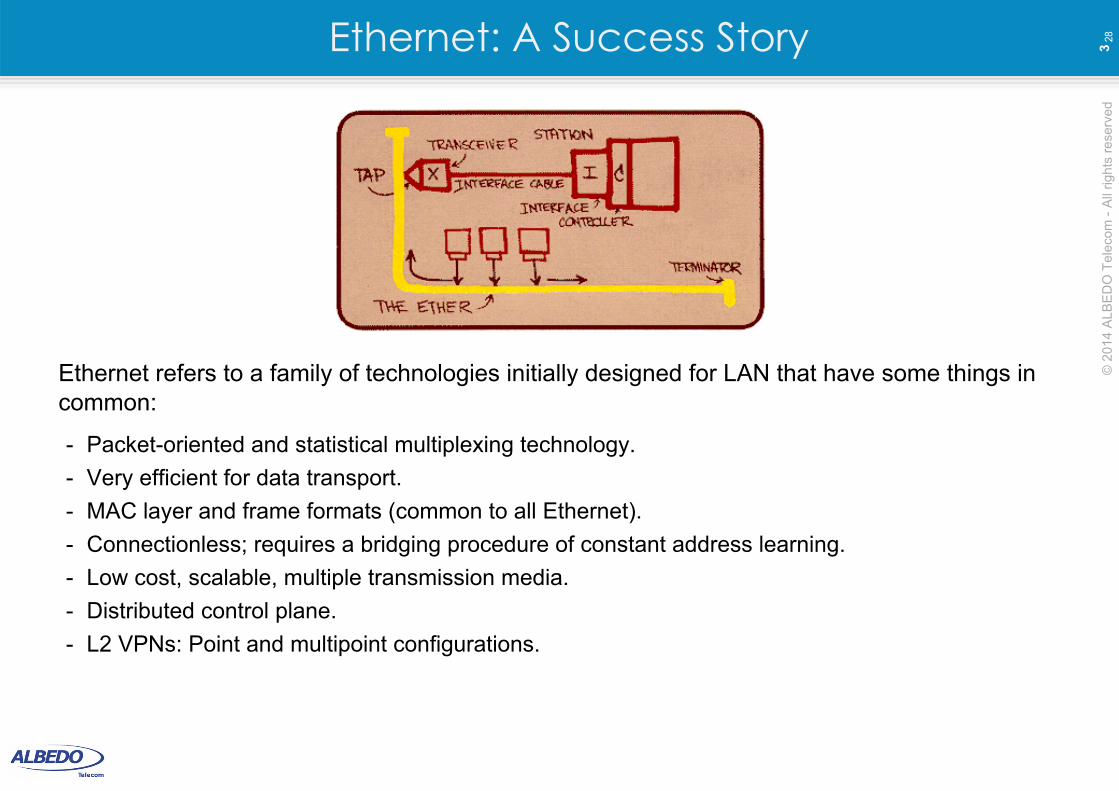
Ethernet refers to a family of technologies initially designed for LAN that have some things in common:
- Packet-oriented and statistical multiplexing technology.
- Very efficient for data transport.
- MAC layer and frame formats (common to all Ethernet).
- Connectionless; requires a bridging procedure of constant address learning.
- Low cost, scalable, multiple transmission media.
- Distributed control plane.
- L2 VPNs: Point and multipoint configurations.
© 2
014
ALB
ED
O T
ele
com
- A
ll rig
hts
re
serv
ed
4 2
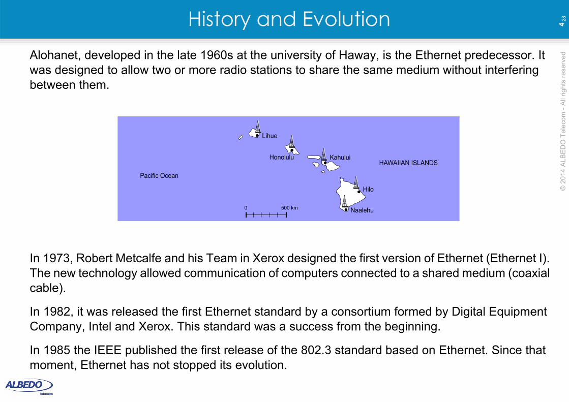
8History and EvolutionAlohanet, developed in the late 1960s at the university of Haway, is the Ethernet predecessor. It was designed to allow two or more radio stations to share the same medium without interfering between them.
In 1973, Robert Metcalfe and his Team in Xerox designed the first version of Ethernet (Ethernet I). The new technology allowed communication of computers connected to a shared medium (coaxial cable).
In 1982, it was released the first Ethernet standard by a consortium formed by Digital Equipment Company, Intel and Xerox. This standard was a success from the beginning.
In 1985 the IEEE published the first release of the 802.3 standard based on Ethernet. Since that moment, Ethernet has not stopped its evolution.
Lihue
Honolulu Kahului
Hilo
Naalehu0 500 km
HAWAIIAN ISLANDS
Pacific Ocean
© 2
014
ALB
ED
O T
ele
com
- A
ll rig
hts
re
serv
ed
5 2
8Ethernet and the OSI Reference Model
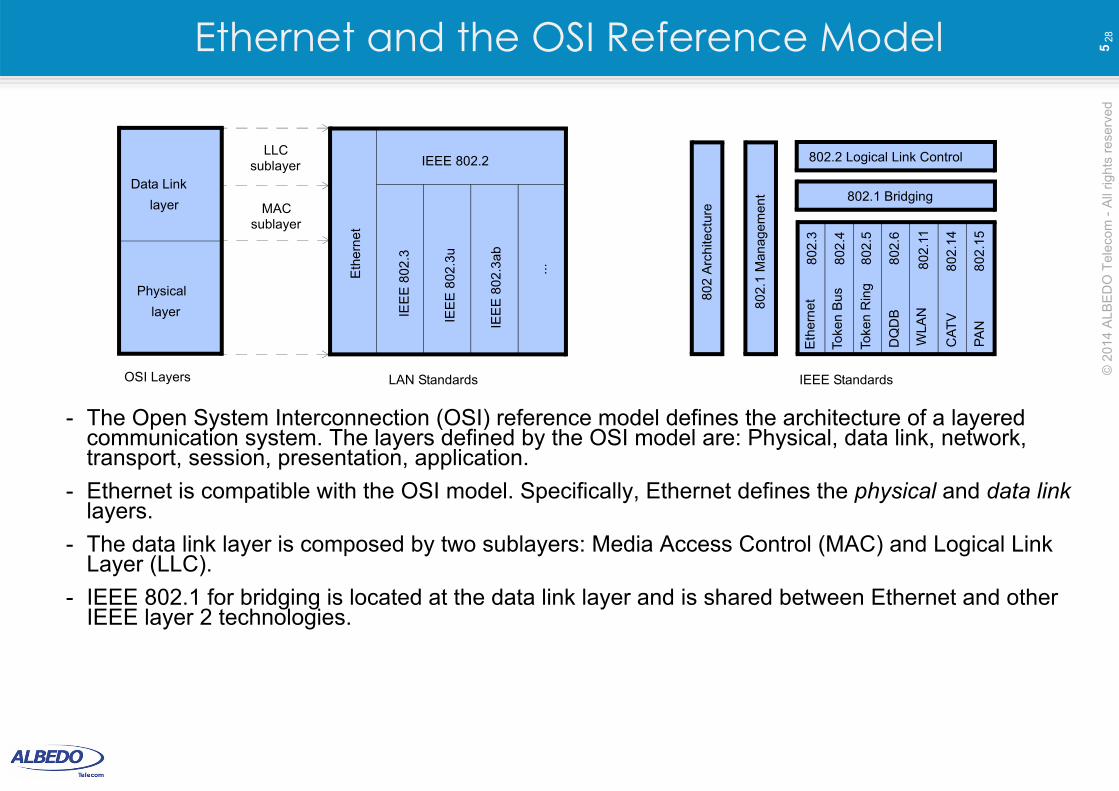
- The Open System Interconnection (OSI) reference model defines the architecture of a layered communication system. The layers defined by the OSI model are: Physical, data link, network, transport, session, presentation, application.
- Ethernet is compatible with the OSI model. Specifically, Ethernet defines the physical and data link layers.
- The data link layer is composed by two sublayers: Media Access Control (MAC) and Logical Link Layer (LLC).
- IEEE 802.1 for bridging is located at the data link layer and is shared between Ethernet and other IEEE layer 2 technologies.
Physical
layer
Data Link
layer
LLCsublayer
MACsublayer
Eth
ern
et
IEEE 802.2
IEE
E 8
02.3
IEE
E 8
02.3
u
IEE
E 8
02
.3ab
...
Eth
ern
et
Toke
n B
us
Toke
n R
ing
DQ
DB
WLA
N
CA
TV
PA
N
802.1 Bridging
802.2 Logical Link Control
802
.1 M
ana
gem
ent
802
Arc
hite
ctur
e
802
.3
802
.4
802
.5
802
.6
802
.11
802
.14
802
.15
OSI Layers LAN Standards IEEE Standards
© 2
014
ALB
ED
O T
ele
com
- A
ll rig
hts
re
serv
ed
6 2
8MAC Addresses
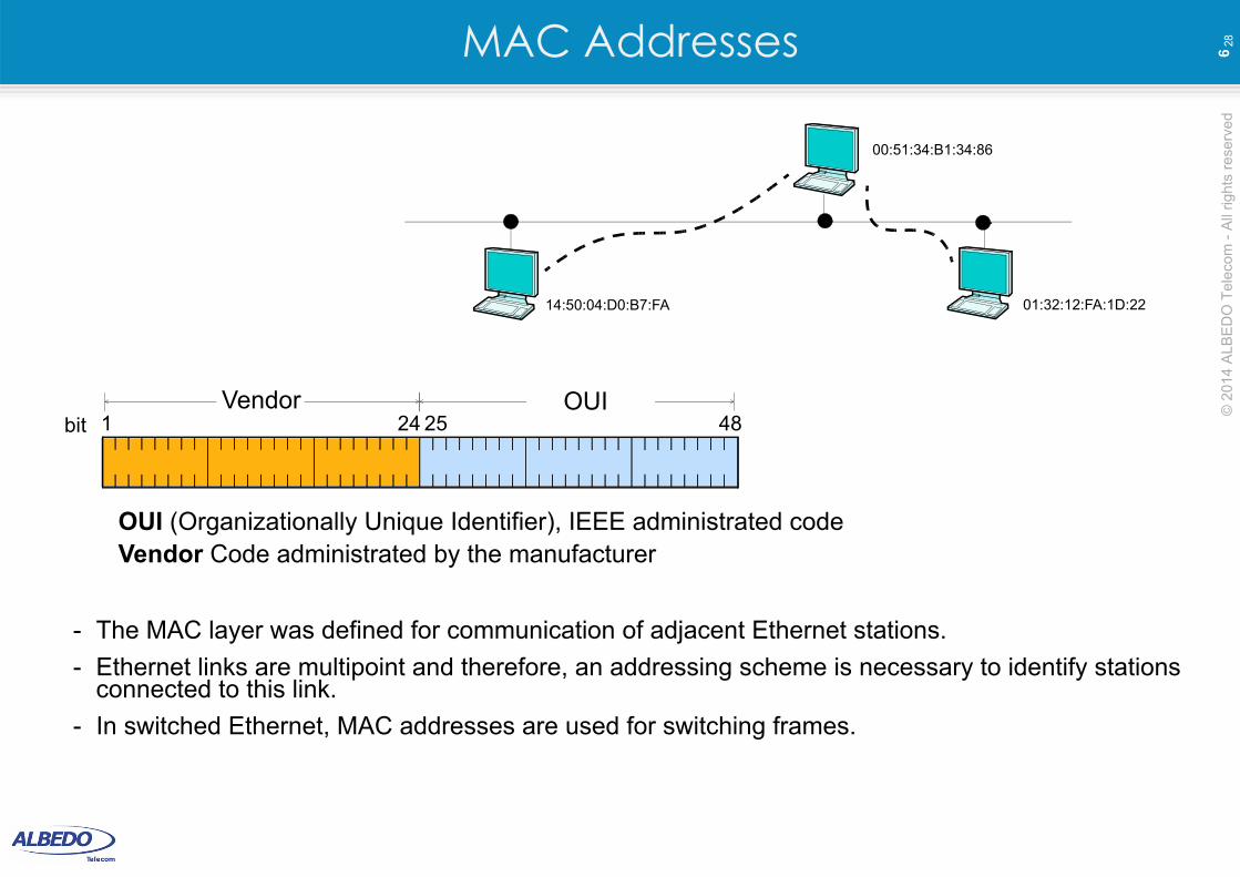
- The MAC layer was defined for communication of adjacent Ethernet stations.
- Ethernet links are multipoint and therefore, an addressing scheme is necessary to identify stations connected to this link.
- In switched Ethernet, MAC addresses are used for switching frames.
14:50:04:D0:B7:FA
00:51:34:B1:34:86
01:32:12:FA:1D:22
1OUI
24 4825Vendor
OUI (Organizationally Unique Identifier), IEEE administrated codeVendor Code administrated by the manufacturer
bit
© 2
014
ALB
ED
O T
ele
com
- A
ll rig
hts
re
serv
ed
7 2
8Framing
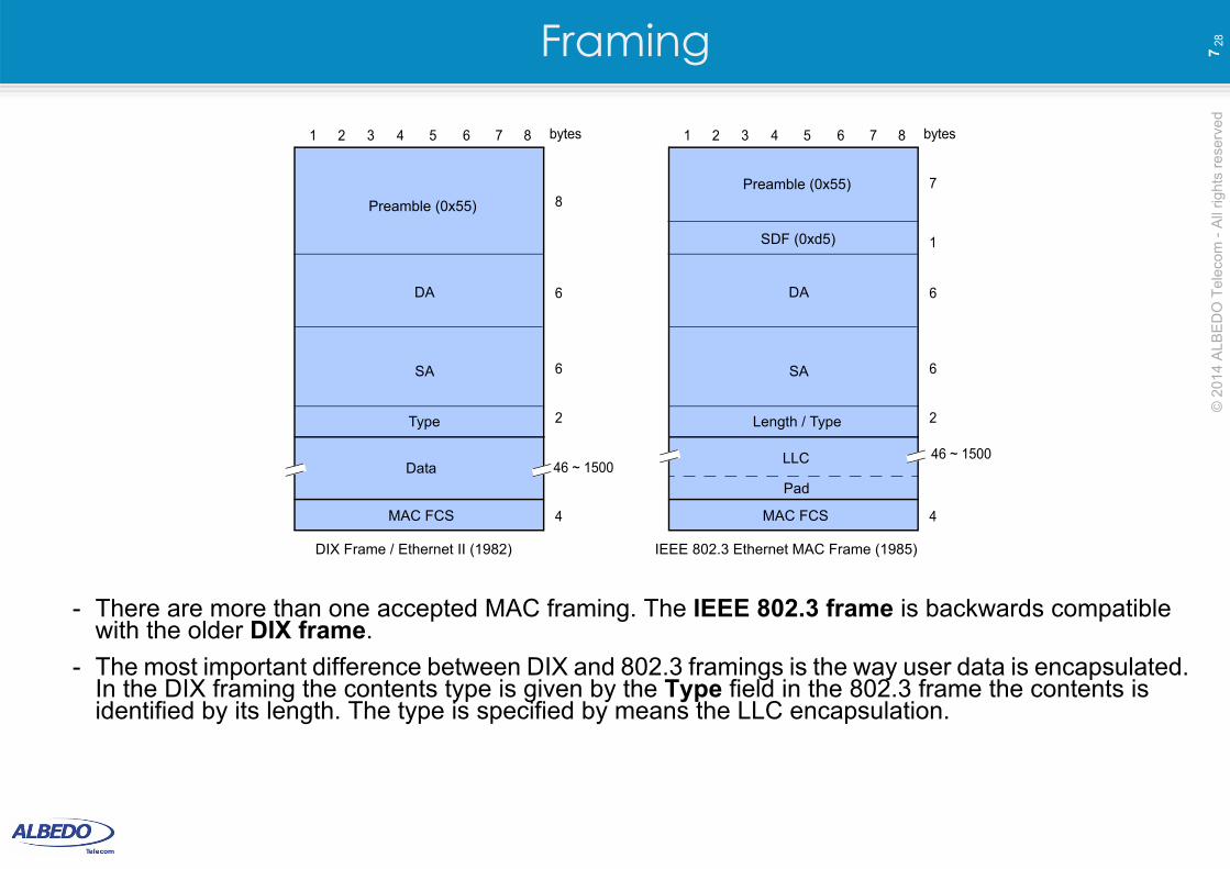
- There are more than one accepted MAC framing. The IEEE 802.3 frame is backwards compatible with the older DIX frame.
- The most important difference between DIX and 802.3 framings is the way user data is encapsulated. In the DIX framing the contents type is given by the Type field in the 802.3 frame the contents is identified by its length. The type is specified by means the LLC encapsulation.
Preamble (0x55)
1 3 5 72 4 6 8
MAC FCS
DA
SA
Type
6
6
2
4
8
bytes
DIX Frame / Ethernet II (1982)
Preamble (0x55)
1 3 5 7
SDF (0xd5)
2 4 6 8
MAC FCS
DA
SA
Length / Type
1
6
6
2
4
7
bytes
IEEE 802.3 Ethernet MAC Frame (1985)
Pad
LLCData 46 ~ 1500
46 ~ 1500
© 2
014
ALB
ED
O T
ele
com
- A
ll rig
hts
re
serv
ed
8 2
8Media Access Control
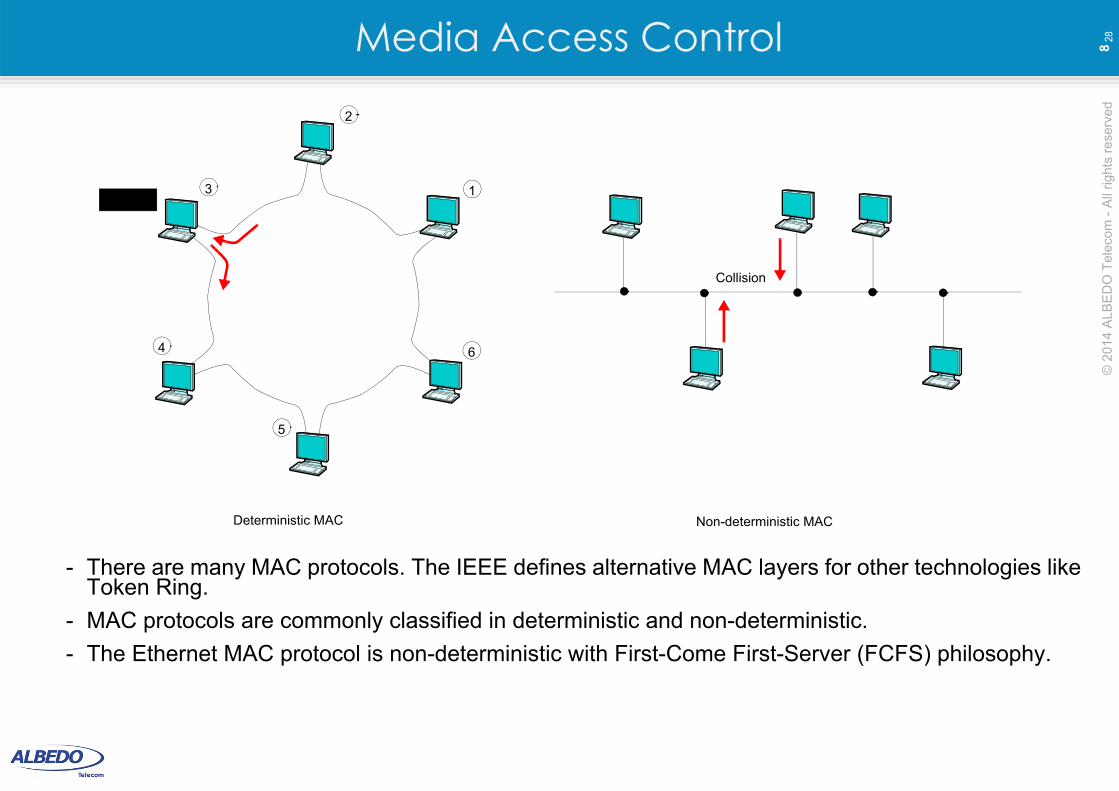
- There are many MAC protocols. The IEEE defines alternative MAC layers for other technologies like Token Ring.
- MAC protocols are commonly classified in deterministic and non-deterministic.
- The Ethernet MAC protocol is non-deterministic with First-Come First-Server (FCFS) philosophy.
1
6
5
4
3
2
Token
Collision
Deterministic MAC Non-deterministic MAC
© 2
014
ALB
ED
O T
ele
com
- A
ll rig
hts
re
serv
ed
9 2
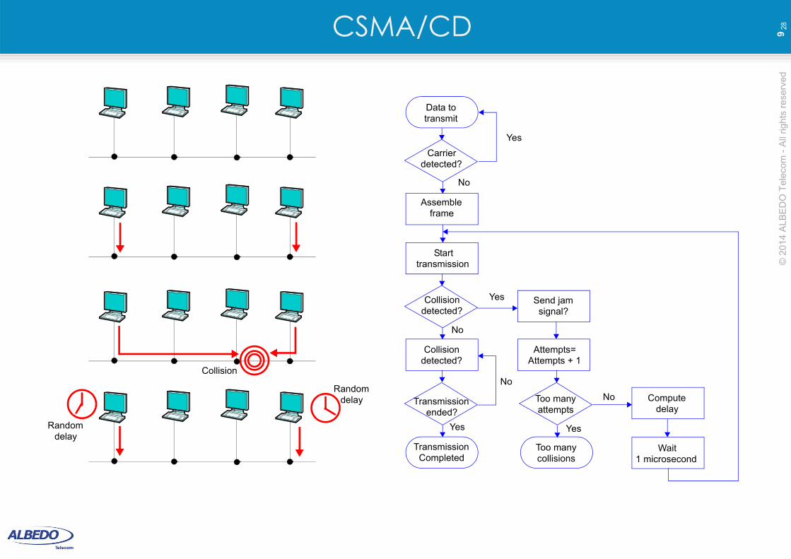
8CSMA/CD
Collision
Randomdelay
Randomdelay
Data totransmit
Carrierdetected?
Assembleframe
Starttransmission
Collisiondetected?
Collisiondetected?
Transmissionended?
TransmissionCompleted
Too manycollisions
Wait1 microsecond
Computedelay
Too manyattempts
Attempts=Attempts + 1
Send jamsignal?
Yes
No
Yes
No
No
Yes Yes
No

© 2
014
ALB
ED
O T
ele
com
- A
ll rig
hts
re
serv
ed
10
28Timing
- The transmitter station sends 64 bits (8 bytes) at the beginning of each frame that enables the receiver to synchronize with the incoming data.
- The first 7 transmitted bytes are known as “preamble”, the 8th byte is the “Start of Frame Delimiter”. This byte is useful for the receiver to recognize the beginning of the frame.
- The DIX version of the Ethernet frame doesn’t have SFD and it has an 8-byte preamble.
- High bit rate Ethernet use to work in full duplex mode. In this case, Ethernet stations can operate in synchronous mode and the preamble is not necessary. However, it is maintained for compatibility of all frame formats.
1st preamble
octet
7th preamble
octet
SFD
FCS
Preamble
© 2
014
ALB
ED
O T
ele
com
- A
ll rig
hts
re
serv
ed
11
28Ethernet Errors- Error (jabber): It is defined in the IEEE 802.3 as a transmission of at least 20000 or 50000 bits.
- Long frame: These kind of frames are defined to be frames longer than the maximum allowed size (1518). VLAN labeled frames are not considered to be long frames even if they exceed this maximum size.
- Short frame: Short frames are shorter than the minimum allowed size with a valid FCS.
- Runt: It designates frames shorter than the minimum allowed size, usually, collision fragments. Therefore, runts have an invalid FCS.
- FCS Error: This kind of errors happens when a frame (with legal size) is received with an invalid FCS due to transmission errors or other reason.
- Alignment Error: It happens when there is not an integer number of bytes in the frame. Usually is at the same time is registered an FCS error.
- Range Error: This error is computed when the value of the length field does not match the actual size of the data field. The Out of Range error is registered when the value of the length field is too big to be valid.
- Ghost: This error designates energy (noise) found in the transmission media that appears to be a frame without a valid FCS. This kind of errors is usually related with cabling problems.
© 2
014
ALB
ED
O T
ele
com
- A
ll rig
hts
re
serv
ed
12
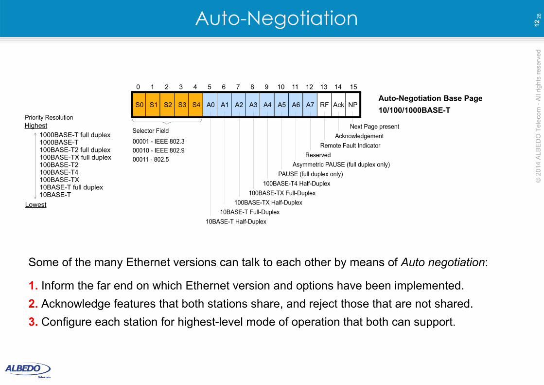
28Auto-Negotiation
Some of the many Ethernet versions can talk to each other by means of Auto negotiation:
1. Inform the far end on which Ethernet version and options have been implemented.
2. Acknowledge features that both stations share, and reject those that are not shared.
3. Configure each station for highest-level mode of operation that both can support.
Acknowledgement
S0 S1 S2 S3 S4
Next Page presentSelector Field
Remote Fault Indicator
PAUSE (full duplex only)
100BASE-T4 Half-Duplex
100BASE-TX Full-Duplex
100BASE-TX Half-Duplex
10BASE-T Full-Duplex
10BASE-T Half-Duplex
Asymmetric PAUSE (full duplex only)
Reserved
Auto-Negotiation Base PageA0 A1 A2 A3 A4 A5 A6 A7 RF Ack NP
0 151 2 3 4 5 6 7 8 9 10 11 12 13 14
00001 - IEEE 802.3
00010 - IEEE 802.9
00011 - 802.5
1000BASE-T full duplex1000BASE-T100BASE-T2 full duplex100BASE-TX full duplex100BASE-T2100BASE-T4100BASE-TX10BASE-T full duplex10BASE-T
Lowest
HighestPriority Resolution
10/100/1000BASE-T
© 2
014
ALB
ED
O T
ele
com
- A
ll rig
hts
re
serv
ed
13
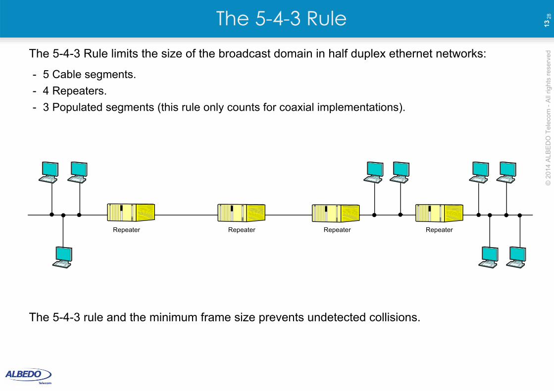
28The 5-4-3 RuleThe 5-4-3 Rule limits the size of the broadcast domain in half duplex ethernet networks:
- 5 Cable segments.
- 4 Repeaters.
- 3 Populated segments (this rule only counts for coaxial implementations).
The 5-4-3 rule and the minimum frame size prevents undetected collisions.
Repeater Repeater Repeater Repeater
© 2
014
ALB
ED
O T
ele
com
- A
ll rig
hts
re
serv
ed
14
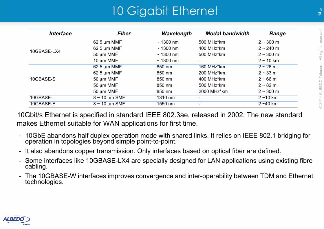
2810 Gigabit Ethernet
10Gbit/s Ethernet is specified in standard IEEE 802.3ae, released in 2002. The new standard makes Ethernet suitable for WAN applications for first time.
- 10GbE abandons half duplex operation mode with shared links. It relies on IEEE 802.1 bridging for operation in topologies beyond simple point-to-point.
- It also abandons copper transmission. Only interfaces based on optical fiber are defined.
- Some interfaces like 10GBASE-LX4 are specially designed for LAN applications using existing fibre cabling.
- The 10GBASE-W interfaces improves convergence and inter-operability between TDM and Ethernet technologies.
Interface Fiber Wavelength Modal bandwidth Range
10GBASE-LX4
62.5 μm MMF ~ 1300 nm 500 MHz*km 2 ~ 300 m62.5 μm MMF ~ 1300 nm 400 MHz*km 2 ~ 240 m50 μm MMF ~ 1300 nm 500 MHz*km 2 ~ 300 m10 μm MMF ~ 1300 nm - 2 ~ 10 km
10GBASE-S
62.5 μm MMF 850 nm 160 MHz*km 2 ~ 26 m62.5 μm MMF 850 nm 200 MHz*km 2 ~ 33 m50 μm MMF 850 nm 400 MHz*km 2 ~ 66 m50 μm MMF 850 nm 500 MHz*km 2 ~ 82 m50 μm MMF 850 nm 2000 MHz*km 2 ~ 300 m
10GBASE-L 8 ~ 10 μm SMF 1310 nm - 2 ~10 km10GBASE-E 8 ~ 10 μm SMF 1550 nm - 2 ~40 km
© 2
014
ALB
ED
O T
ele
com
- A
ll rig
hts
re
serv
ed
15
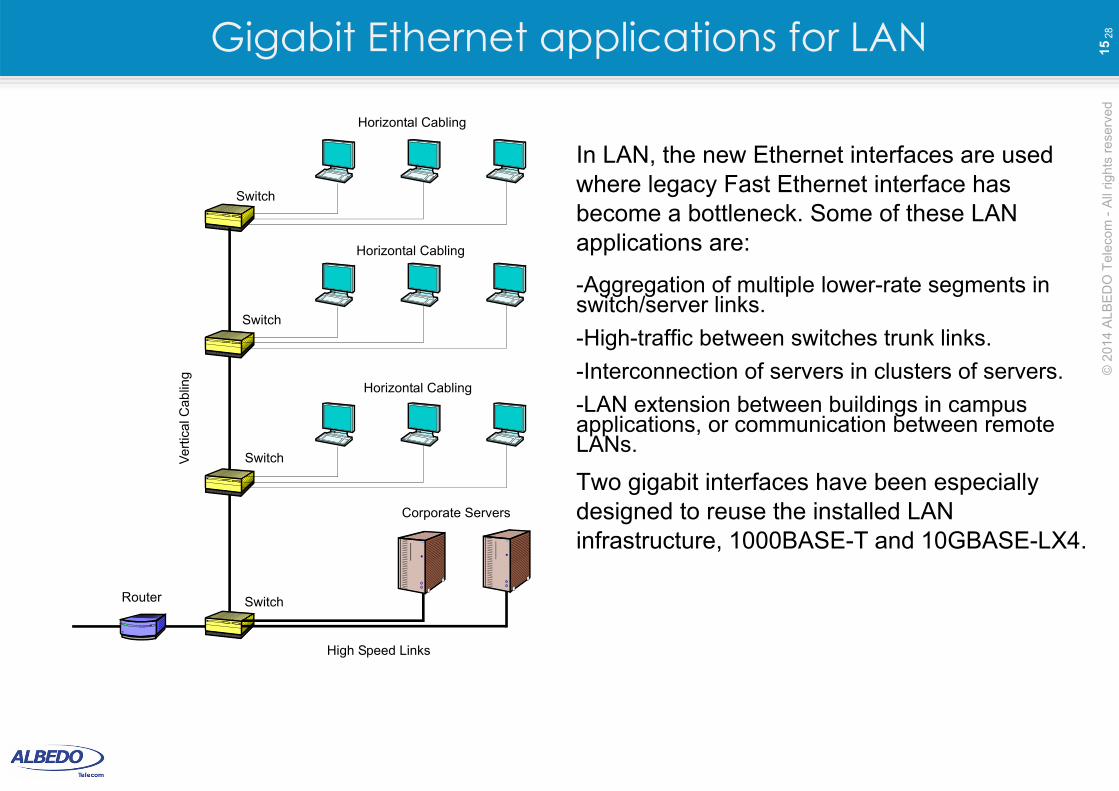
28Gigabit Ethernet applications for LAN
In LAN, the new Ethernet interfaces are used where legacy Fast Ethernet interface has become a bottleneck. Some of these LAN applications are:
-Aggregation of multiple lower-rate segments in switch/server links.
-High-traffic between switches trunk links.
-Interconnection of servers in clusters of servers.
-LAN extension between buildings in campus applications, or communication between remote LANs.
Two gigabit interfaces have been especially designed to reuse the installed LAN infrastructure, 1000BASE-T and 10GBASE-LX4.
Horizontal Cabling
Horizontal Cabling
Horizontal Cabling
High Speed Links
Ve
rtic
al C
ablin
g
Router
Switch
Switch
Switch
Switch
Corporate Servers
© 2
014
ALB
ED
O T
ele
com
- A
ll rig
hts
re
serv
ed
16
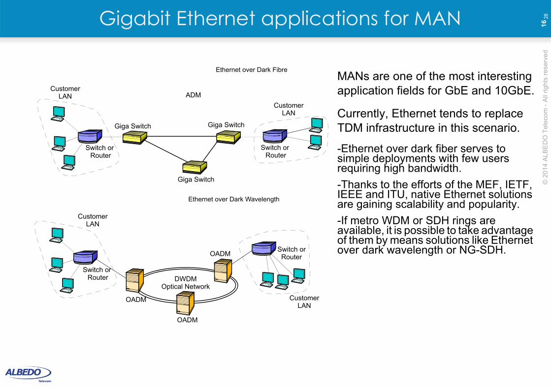
28Gigabit Ethernet applications for MAN
MANs are one of the most interesting application fields for GbE and 10GbE.
Currently, Ethernet tends to replace TDM infrastructure in this scenario.
-Ethernet over dark fiber serves to simple deployments with few users requiring high bandwidth.
-Thanks to the efforts of the MEF, IETF, IEEE and ITU, native Ethernet solutions are gaining scalability and popularity.
-If metro WDM or SDH rings are available, it is possible to take advantage of them by means solutions like Ethernet over dark wavelength or NG-SDH.
ADM
Giga Switch Giga Switch
Switch or Router
CustomerLAN
Switch or Router
CustomerLAN
Switch or Router
CustomerLAN
DWDM
OADM
OADM
OADM
Optical Network
Switch or
CustomerLAN
Router
Giga Switch
Ethernet over Dark Fibre
Ethernet over Dark Wavelength
© 2
014
ALB
ED
O T
ele
com
- A
ll rig
hts
re
serv
ed
17
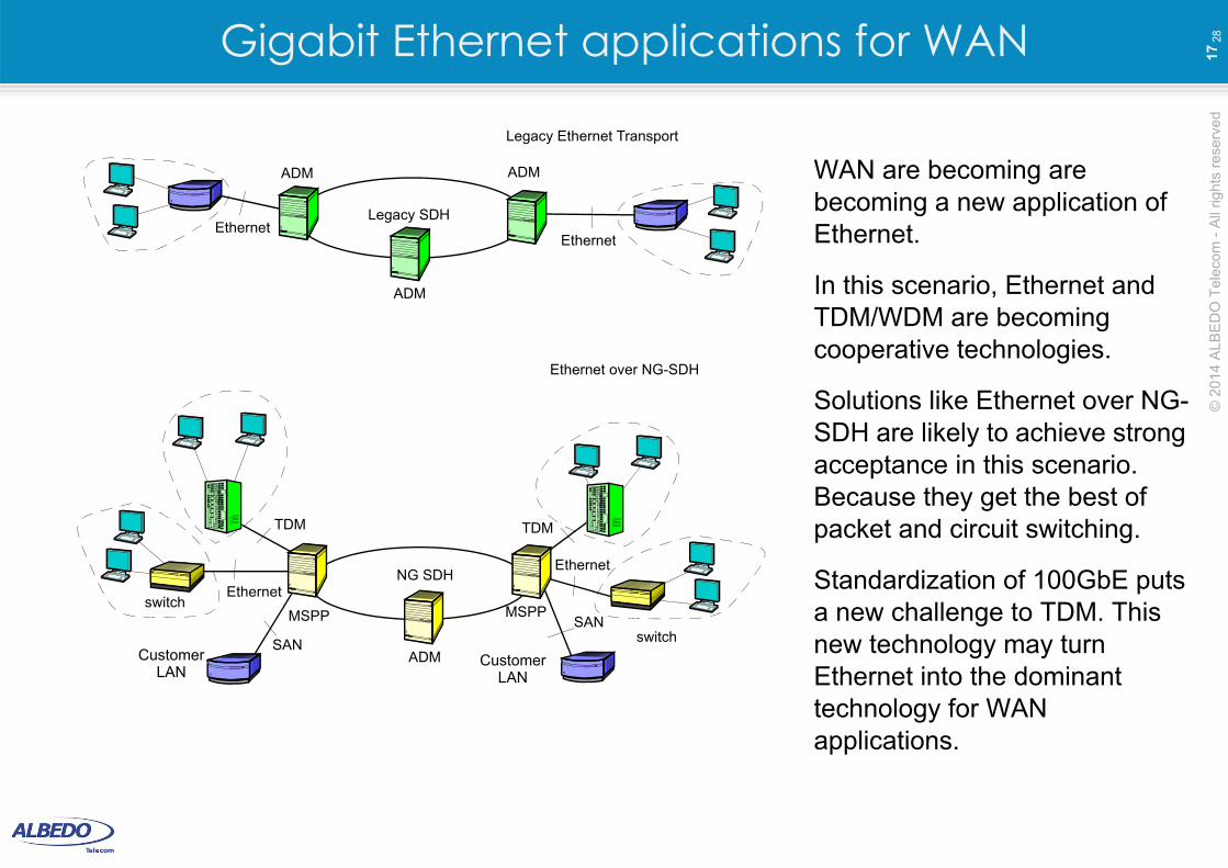
28Gigabit Ethernet applications for WAN
WAN are becoming are becoming a new application of Ethernet.
In this scenario, Ethernet and TDM/WDM are becoming cooperative technologies.
Solutions like Ethernet over NG-SDH are likely to achieve strong acceptance in this scenario. Because they get the best of packet and circuit switching.
Standardization of 100GbE puts a new challenge to TDM. This new technology may turn Ethernet into the dominant technology for WAN applications.
NG SDH
MSPPswitch
EthernetMSPP
switch
Legacy SDH
ADM
SAN
TDM TDM
SAN
Ethernet
ADM
ADM
ADM
Ethernet
Ethernet
CustomerLAN
CustomerLAN
Legacy Ethernet Transport
Ethernet over NG-SDH
Switched Ethernet
© 2
014
ALB
ED
O T
ele
com
- A
ll rig
hts
re
serv
ed
19
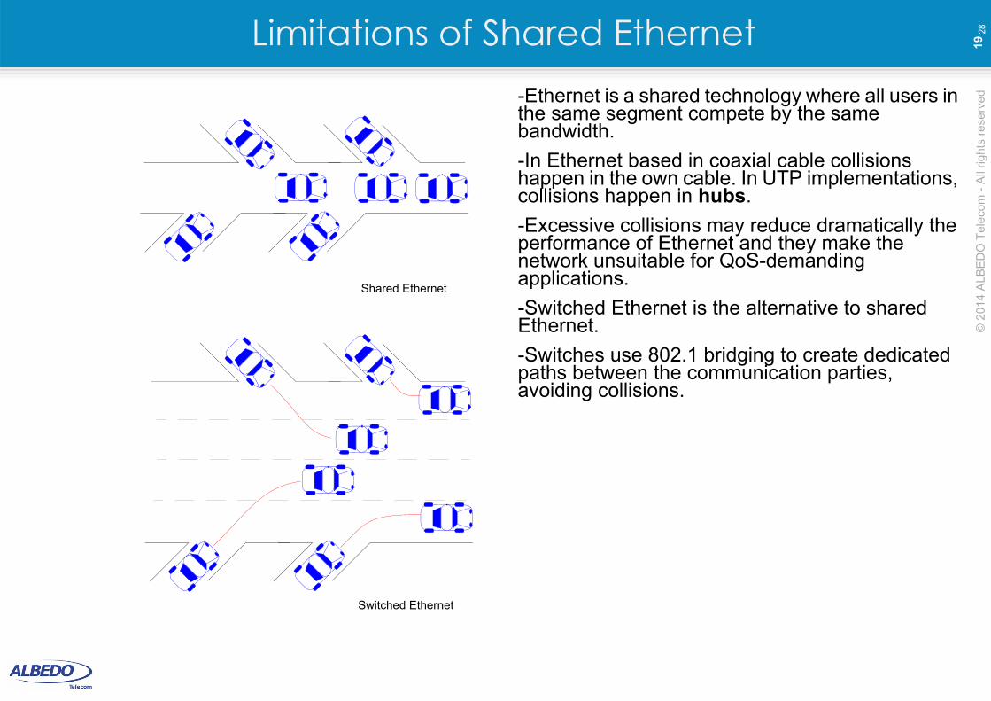
28Limitations of Shared Ethernet-Ethernet is a shared technology where all users in the same segment compete by the same bandwidth.
-In Ethernet based in coaxial cable collisions happen in the own cable. In UTP implementations, collisions happen in hubs.
-Excessive collisions may reduce dramatically the performance of Ethernet and they make the network unsuitable for QoS-demanding applications.
-Switched Ethernet is the alternative to shared Ethernet.
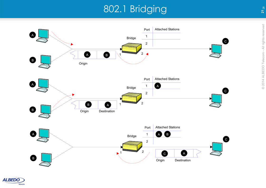
-Switches use 802.1 bridging to create dedicated paths between the communication parties, avoiding collisions.
Switched Ethernet
Shared Ethernet
© 2
014
ALB
ED
O T
ele
com
- A
ll rig
hts
re
serv
ed
20
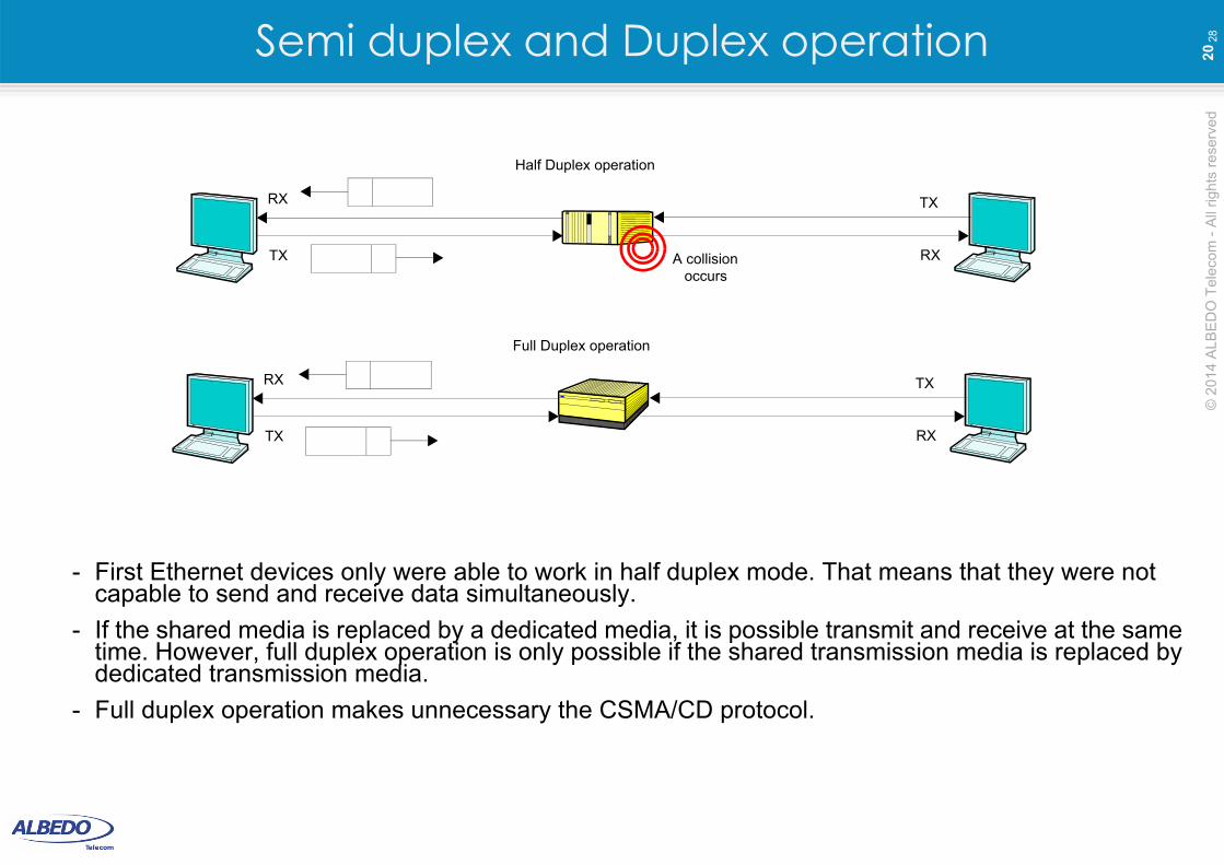
28Semi duplex and Duplex operation
- First Ethernet devices only were able to work in half duplex mode. That means that they were not capable to send and receive data simultaneously.
- If the shared media is replaced by a dedicated media, it is possible transmit and receive at the same time. However, full duplex operation is only possible if the shared transmission media is replaced by dedicated transmission media.
- Full duplex operation makes unnecessary the CSMA/CD protocol.
Full Duplex operation
TX RX
A collisionoccurs
Half Duplex operation
TX RX
TX
TX
RX
RX
© 2
014
ALB
ED
O T
ele
com
- A
ll rig
hts
re
serv
ed
21
28802.1 Bridging
DestinationOrigin
BridgeA
B
C
A B 1 2
1
Attached StationsPort
2
DestinationOrigin
BridgeA
B
C
B A 1 2
1
Attached StationsPort
2
DestinationOrigin
BridgeA
B
C
AC1 2
1
Attached StationsPort
2
A
A B
© 2
014
ALB
ED
O T
ele
com
- A
ll rig
hts
re
serv
ed
22
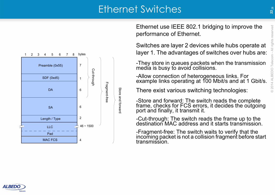
28Ethernet SwitchesEthernet use IEEE 802.1 bridging to improve the performance of Ethernet.
Switches are layer 2 devices while hubs operate at layer 1. The advantages of switches over hubs are:
-They store in queues packets when the transmission media is busy to avoid collisions.
-Allow connection of heterogeneous links. For example links operating at 100 Mbit/s and at 1 Gbit/s.
There exist various switching technologies:
-Store and forward: The switch reads the complete frame, checks for FCS errors, it decides the outgoing port and finally, it transmit it.
-Cut-through: The switch reads the frame up to the destination MAC address and it starts transmission.
-Fragment-free: The switch waits to verify that the incoming packet is not a collision fragment before start transmission.
Preamble (0x55)
1 3 5 7
SDF (0xd5)
2 4 6 8
MAC FCS
DA
SA
Length / Type
1
6
6
2
4
7
bytes
Pad
LLC 46 ~ 1500
Cut-through
Fra
gme
nt-free
Store an
d forw
ard
© 2
014
ALB
ED
O T
ele
com
- A
ll rig
hts
re
serv
ed
23
28Segmentation and Micro-segmentation
Switch
Segment B
Segment A Segment C
One segment
Switch
SwitchSwitch
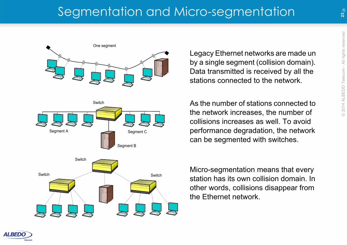
Legacy Ethernet networks are made un by a single segment (collision domain). Data transmitted is received by all the stations connected to the network.
As the number of stations connected to the network increases, the number of collisions increases as well. To avoid performance degradation, the network can be segmented with switches.
Micro-segmentation means that every station has its own collision domain. In other words, collisions disappear from the Ethernet network.
© 2
014
ALB
ED
O T
ele
com
- A
ll rig
hts
re
serv
ed
24
28Limitations of bridging: The STP
Switch A Switch B
ServerHost
Switch A Switch B
ServerHost
Switch A Switch B
ServerHost
Repeatedframes
Unstableswitching tables
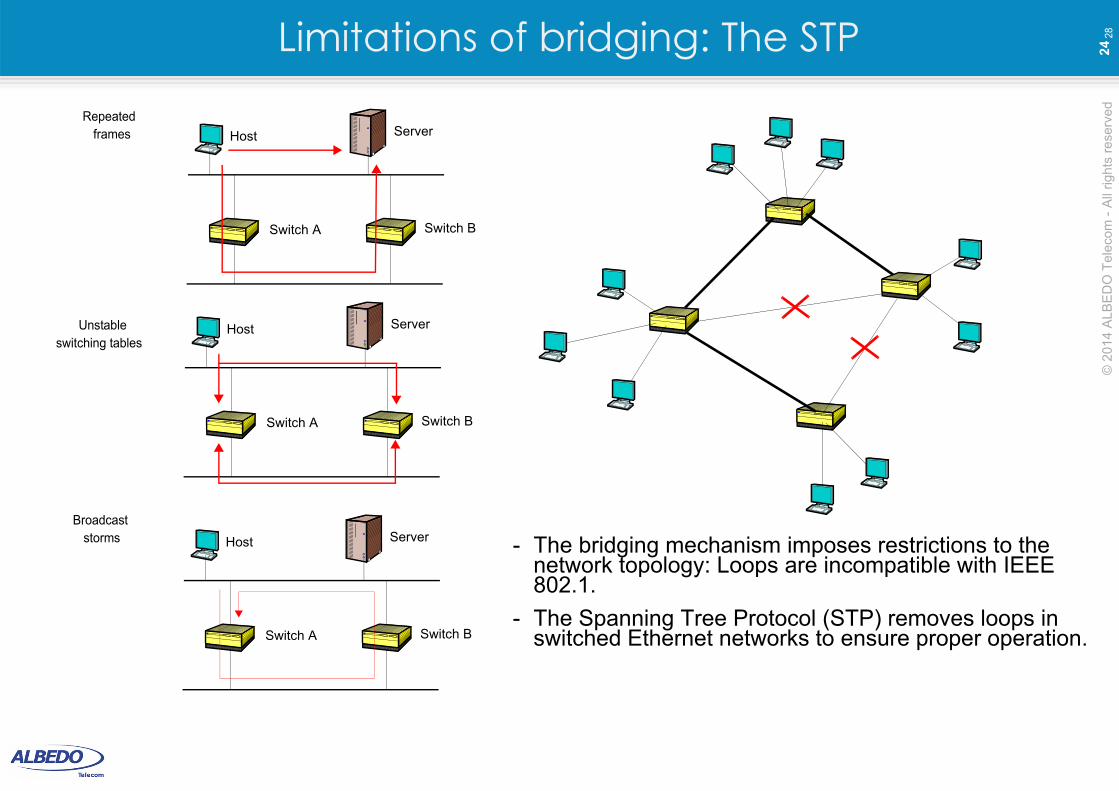
Broadcaststorms - The bridging mechanism imposes restrictions to the
network topology: Loops are incompatible with IEEE 802.1.
- The Spanning Tree Protocol (STP) removes loops in switched Ethernet networks to ensure proper operation.
© 2
014
ALB
ED
O T
ele
com
- A
ll rig
hts
re
serv
ed
25
28Limitations of bridging: VLANs
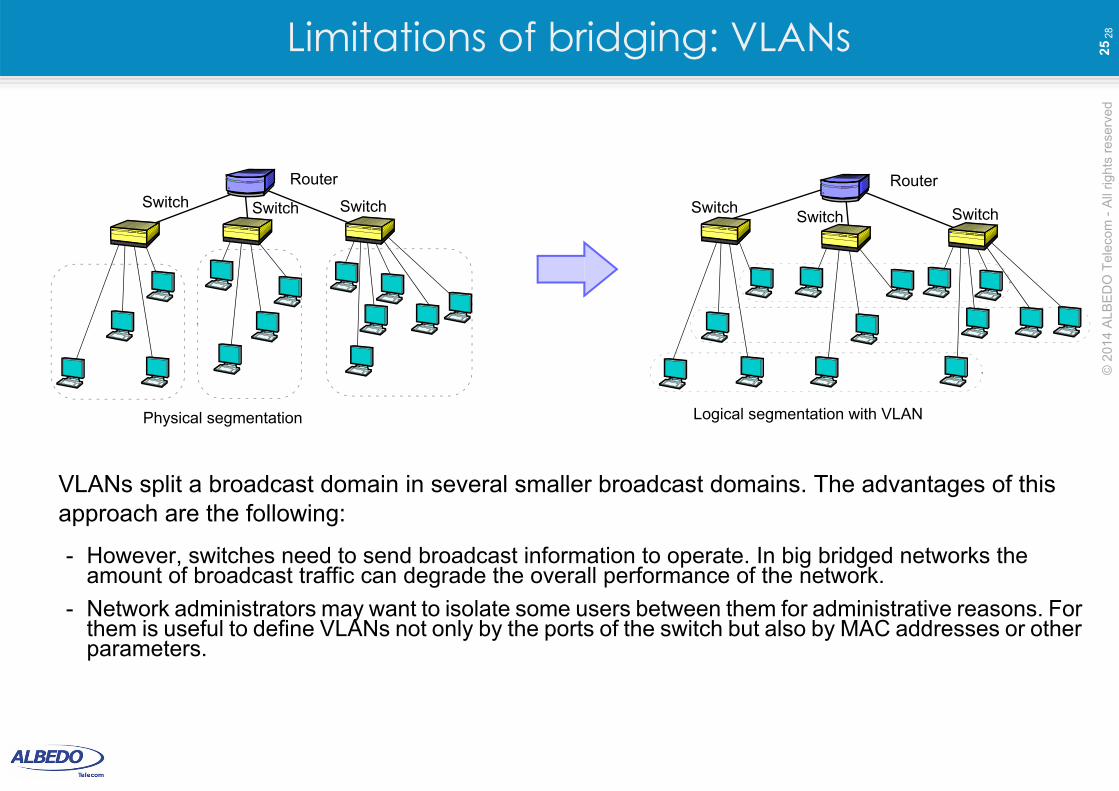
VLANs split a broadcast domain in several smaller broadcast domains. The advantages of this approach are the following:
- However, switches need to send broadcast information to operate. In big bridged networks the amount of broadcast traffic can degrade the overall performance of the network.
- Network administrators may want to isolate some users between them for administrative reasons. For them is useful to define VLANs not only by the ports of the switch but also by MAC addresses or other parameters.
RouterRouter
Logical segmentation with VLANPhysical segmentation
Switch SwitchSwitchSwitch SwitchSwitch
© 2
014
ALB
ED
O T
ele
com
- A
ll rig
hts
re
serv
ed
26
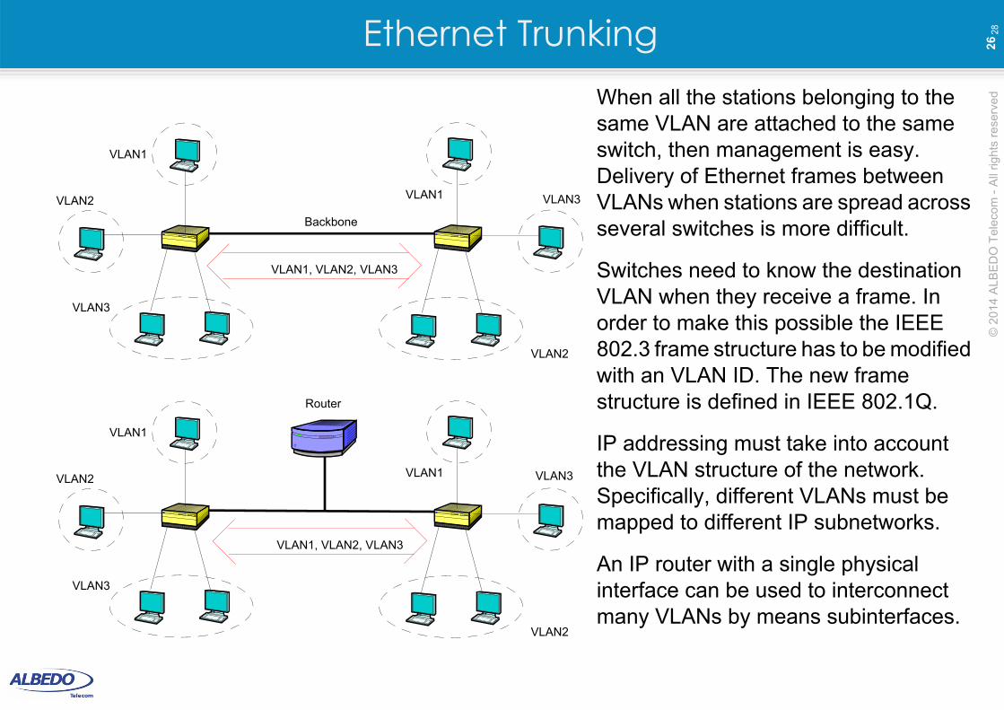
28Ethernet TrunkingWhen all the stations belonging to the same VLAN are attached to the same switch, then management is easy. Delivery of Ethernet frames between VLANs when stations are spread across several switches is more difficult.
Switches need to know the destination VLAN when they receive a frame. In order to make this possible the IEEE 802.3 frame structure has to be modified with an VLAN ID. The new frame structure is defined in IEEE 802.1Q.
IP addressing must take into account the VLAN structure of the network. Specifically, different VLANs must be mapped to different IP subnetworks.
An IP router with a single physical interface can be used to interconnect many VLANs by means subinterfaces.
VLAN1
VLAN1
VLAN2 VLAN3
VLAN3
VLAN2
VLAN1
VLAN1
VLAN2
VLAN3
VLAN2
Router
VLAN1, VLAN2, VLAN3
VLAN1, VLAN2, VLAN3
Backbone
VLAN3
© 2
014
ALB
ED
O T
ele
com
- A
ll rig
hts
re
serv
ed
27
28IEEE 802.1Q Labeling
Preamble (0x55)
1 3 5 7
SDF (0xd5)
2 4 6 8
FCS
MAC DA
MAC SA
Ethertype (Q-tagged frame)
1
6
6
2
4
7
bytes
Q-tagged frame (IEEE 802.1Q)
T / L
TCI 2
2
VL
AN
tag
PRI
VLAN ID1
1
TCI Format
1 3 5 72 4 6 8 bytes
CFI
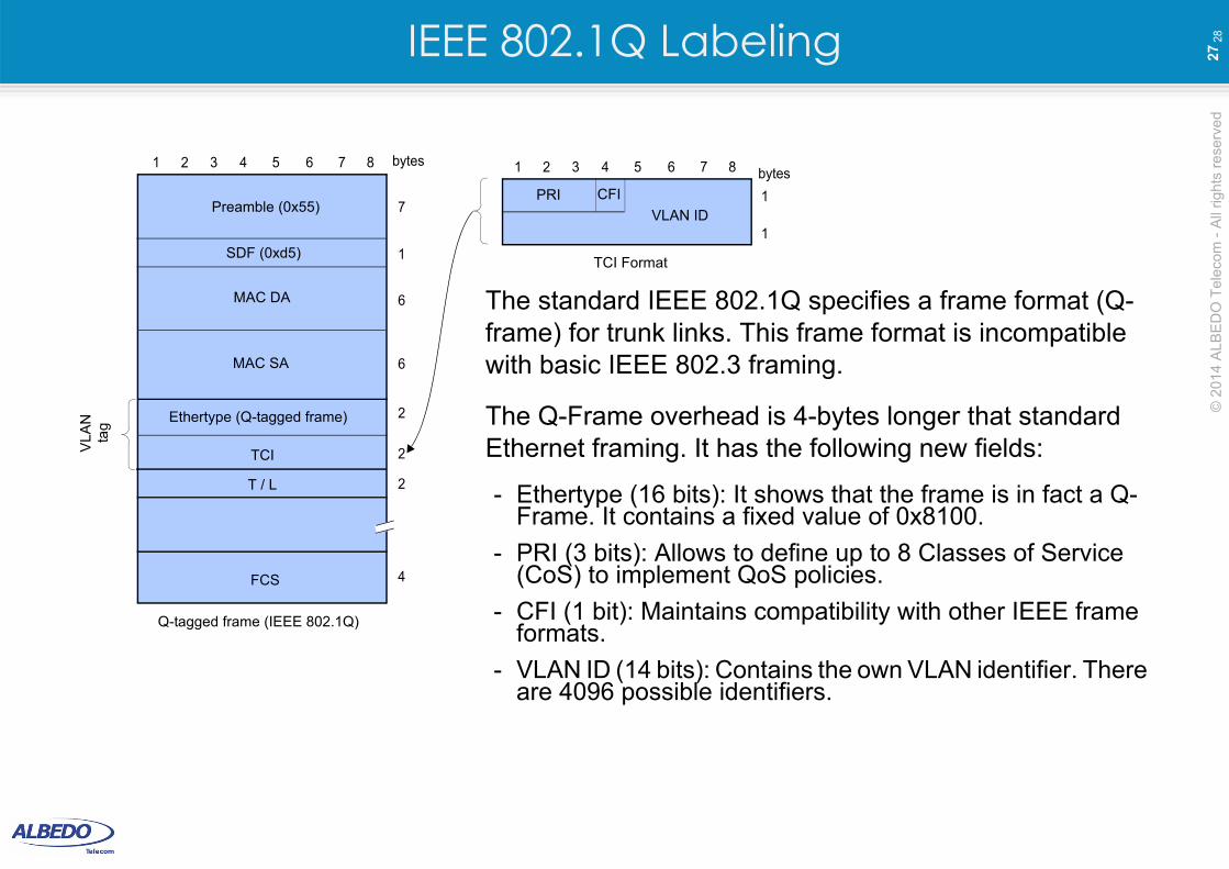
The standard IEEE 802.1Q specifies a frame format (Q-frame) for trunk links. This frame format is incompatible with basic IEEE 802.3 framing.
The Q-Frame overhead is 4-bytes longer that standard Ethernet framing. It has the following new fields:
- Ethertype (16 bits): It shows that the frame is in fact a Q-Frame. It contains a fixed value of 0x8100.
- PRI (3 bits): Allows to define up to 8 Classes of Service (CoS) to implement QoS policies.
- CFI (1 bit): Maintains compatibility with other IEEE frame formats.
- VLAN ID (14 bits): Contains the own VLAN identifier. There are 4096 possible identifiers.

That’s all, thanks