Embed Size (px)
Citation preview

Ethernet CFM, Y.1731 Basic Concepts,Configuration, and Implementation
Document ID: 117457
Contributed by Amit Goyal, Cisco TAC Engineer.Apr 09, 2014
Contents
IntroductionPrerequisites Requirements Components UsedBackground InformationEthernet OAM Ethernet OAM Protocols PositionCFM Overview Key CFM MechanismsCFM Concepts Maintenance Domain Maintenance Association Maintenance Point − Maintenance End Point Maintenance Domain Intermediate Point UP MEP UP MEP − Frame Forwarding DOWN MEP DOWN MEP − Frame Forwarding MP Placement in a Bridge Port MAs and UP/DOWN MEPs Applicability of UP/DOWN EPs in SwitchesFault Management CFM Protocols Continuity Check Protocol Loopback Protocol Linktrace Protocol Implementation CasesConfiguration Management (UP MEP) Topology Verify Show CommandsConfiguration Management (DOWN MEP) Verify Show Commands Verify Continuity CheckDebug CommandsPerformance Management Key Performance Indicators (KPIs) Measuring KPIs Frame Delay/Delay Variation Frame Loss Cisco Performanace Management Solution

Usage Guidelines and Restrictions PrerequisitesConfiguration Management VerifyDebug CommandsRelated Information
Introduction
This document provides awareness of the Connectivity Fault Management (CFM) technology, configuration,post−checks, and troubleshooting. The basic concepts of CFM, CFM's building blocks, a configuration guide,show commands, and Wireshark analysis of CFM messages is provided. This document does not explainhardware limitations or the supported interface for CFM to work.
Prerequisites
Requirements
Cisco recommends that you have knowledge of these topics:
Ethernet technologies• Ethernet Virtual Connections (EVCs)•
Components Used
This document is not restricted to specific software and hardware versions.
The information in this document was created from the devices in a specific lab environment. All of thedevices used in this document started with a cleared (default) configuration. If your network is live, make surethat you understand the potential impact of any command.
Background Information
Ethernet CFM is an end−to−end per−service−instance Ethernet layer operation, administration, andmanagement (OAM) protocol. It includes proactive connectivity monitoring, fault verification, and faultisolation for large Ethernet metropolitan−area networks (MANs) and WANs.
The advent of Ethernet as a MAN and WAN technology imposes a new set of OAM requirements onEthernet's traditional operations, which were centered on enterprise networks only. The expansion of Ethernettechnology into the domain of service providers, where networks are substantially larger and more complexthan enterprise networks and the user base is wider, makes operational management of link uptime crucial.More importantly, the timeliness to isolate and respond to a failure becomes mandatory for normalday−to−day operations, and OAM translates directly to the competitiveness of the service provider.

Ethernet OAM
Building Block − IEEE 802.1ag• CFM − IEEE 802.3ah (clause 57)• Ethernet Link OAM (also referred as 802.3 OAM, Link OAM, or Ethernet in the First Mile (EFM)OAM) − ITU−T Y.1731
•
OAM functions and mechanisms for Ethernet−based networks − MEF E−LMI (Ethernet LocalManagement Interface)
•
Ethernet OAM Protocols Position
E−LMI − User to Network Interface (UNI)• Link OAM − Any point−to−point 802.3 link• CFM − End−to−End UNI to UNI• MPLS OAM − within MPLS cloud•
CFM Overview
Family of protocols that provides capabilities to detect, verify, isolate, and report end−to−endEthernet connectivity faults
•
Employs regular Ethernet frames that travel in−band with the customer traffic• Devices that cannot interpret CFM Messages forward them as normal data frames• CFM frames are distinguishable by Ether−Type (0x8902) and dMAC address (for multicastmessages)
•
Standardized by IEEE in 2007 IEEE std. 802.1ag−2007•
Key CFM Mechanisms
Nested Maintenance Domains (MDs) that break up the responsibilities for network administration of agiven end−to−end service
•
Maintenance Associations (MAs) that monitor service instances under a given MD• Maintenance Points (MPs) that generate and respond to CFM Protocol Data Units (PDUs)• Protocols (Continuity Check, Loopback, and Linktrace) used for Fault Management activities•
CFM Concepts
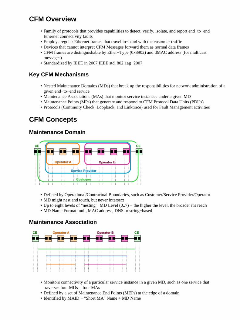
Maintenance Domain
Defined by Operational/Contractual Boundaries, such as Customer/Service Provider/Operator• MD might nest and touch, but never intersect• Up to eight levels of "nesting": MD Level (0..7) − the higher the level, the broader it's reach• MD Name Format: null, MAC address, DNS or string−based•
Maintenance Association
Monitors connectivity of a particular service instance in a given MD, such as one service thattraverses four MDs = four MAs
•
Defined by a set of Maintenance End Points (MEPs) at the edge of a domain• Identified by MAID − "Short MA" Name + MD Name•

Short MA Name Format − Vlan−ID, VPN−ID, integer or string−based•
Maintenance Point − Maintenance End Point
Maintenance Association End Point• Define the boundaries of an MD• Support the detection of connectivity failures between any pair of MEPs in an MA• Associated per MA and identified by a MEPID (1−8191)• Can initiate and respond to CFM PDUs•
Maintenance Domain Intermediate Point
Maintenance Domain Intermediate Point (MIP)• Supports the discovery of paths among MEPs and location of faults along those paths• Can be associated per MD and VLAN/EVC (manually or automatically created)• Can add, check, and respond to received CFM PDUs•
UP MEP
CFM PDUs generated by the MEP are sent towards the Bridge's Relay Function and not via the wireconnected to the port where the MEP is configured
•
CFM PDUs to be responded by the MEP are expected to arrive via the Bridge's Relay Function• Applicable to switches•

UP MEP − Frame Forwarding
DOWN MEP
CFM PDUs generated by the MEP are sent via the wire connected to the port where the MEP isconfigured
•
CFM PDUs to be responded by the MEP are expected to arrive via the wire connected to the portwhere the MEP is configured
•
Port MEP − special Down MEP at level zero (0) used to detect faults at the link level (rather thanservice)
•
Applicable to routers and switches•
DOWN MEP − Frame Forwarding

MP Placement in a Bridge Port
MAs and UP/DOWN MEPs

Applicability of UP/DOWN EPs in Switches
DOWN MEPs are typically used for MAs that span a single link• UP MEPs are commonly used for MAs with a wider reach, such as end−to−end and beyond a singlelink
•
Fault Management
CFM Protocols
There are three (3) protocols defined by CFM:
Continuity Check ProtocolFault Detection♦ Fault Notification♦ Fault Recovery♦
1.
Loopback ProtocolFault Verification♦
2.
Linktrace ProtocolPath Discovery and Fault Isolation♦
3.
Continuity Check Protocol
Used for Fault Detection, Notification, and Recovery• Per−Maintenance Association multicast "heart−beat" messages are transmitted at a configurableperiodic interval by MEPs (3.3ms, 10ms, 100ms, 1s, 10s, 1min, 10min) − Uni−directional (noresponse required)
•
Carries status of port on which MEP is configured• Catalogued by MIPs at the same MD−Level, terminated by remote MEPs in the same MA•
Loopback Protocol
Used for Fault Verification − Ethernet Ping• MEP can transmit a unicast LBM to a MEP or MIP in the same MA• MEP can also transmit a multicast LBM (defined by ITU−T Y.1731), where only MEPs in the sameMA respond
•
Receiving MP responds by transforming the LBM into a unicast LBR sent back to the originatingMEP
•
Linktrace Protocol
Used for Path Discovery and Fault Isolation − Ethernet Traceroute• MEP can transmit a multicast message (LTM) in order to discover the MPs and path to a MIP or MEPin the same MA
•
Each MIP along the path and the terminating MP return a unicast LTR to originating MEP•
In order to put all three protocols together and implement them in the network, complete these steps:
Run a connectivity check in order to proactively detect a soft or hard failure.1. Upon a failure detection, use loopback, CCM DB, and Error DB in order to verify it.2. Upon verification, run traceroute in order to isolate it. Multiple segment LBMs can also be used toisolate the fault.
3.

If the isolated fault points to a virtual circuit, then the OAM tools for that technology can be used tofurther fault isolation; as an example for MPLS PW, VCCV and MPLS ping can be used.
4.
Implementation Cases
Configuration Management (UP MEP)
Topology
In order to explore the configuration, a small topology was built for demonstration. The names used forDomain, Service name, and EVC Name are shown here:
Domain: ISPdomainDomain level: 5Service Name: XCONN_EVCEVC Name: EVC_CE1
PE1:

−−−−−−−−−−−−−−−−−−−−−−−−−−−Enabling CFM globally−−−−−−−−−−−−−−−−−−−−−−−−−−−−−−−−−−−−−ethernet cfm ieeeethernet cfm distribution enableethernet cfm globalethernet cfm traceroute cacheethernet cfm alarm notification allethernet cfm domain ISPdomain level 5 service XCONN_EVC evc EVC_CE1 continuity−check
−−−−−−−−−−−−−−−−−−−−−−−−−−−Enabling CFM MEP under EVC−−−−−−−−−−−−−−−−−−−−−−−−−−−−
int gig4/2service instance 2100 ethernet EVC_CE1 encapsulation dot1q 2100 xconnect 192.168.3.3 2100 encapsulation mpls cfm mep domain ISPdomain mpid 102 monitor loss counter
PE3:
−−−−−−−−−−−−−−−−−−−−−−−−−−−Enabling CFM globally−−−−−−−−−−−−−−−−−−−−−−−−−−−−−−−−−−−−−
ethernet cfm ieeeethernet cfm distribution enableethernet cfm globalethernet cfm traceroute cacheethernet cfm alarm notification allethernet cfm domain ISPdomain level 5 service XCONN_EVC evc EVC_CE1 continuity−check
−−−−−−−−−−−−−−−−−−−−−−−−−−−Enabling CFM MEP under EVC−−−−−−−−−−−−−−−−−−−−−−−−−−−−
int gig4/2service instance 2100 ethernet EVC_CE1 encapsulation dot1q 2100 xconnect 192.168.1.1 2100 encapsulation mpls cfm mep domain ISPdomain mpid 201 monitor loss counter
Verify
Show Commands
PE1#show ethernet cfm maintenance−points localLocal MEPs:−−−−−−−−−−−−−−−−−−−−−−−−−−−−−−−−−−−−−−−−−−−−−−−−−−−−−−−−−−−−−−−−−−−−−−−−−−−−−−−−MPID Domain Name Lvl MacAddress Type CCOfld Domain Id Dir Port Id MA Name SrvcInst Source EVC name−−−−−−−−−−−−−−−−−−−−−−−−−−−−−−−−−−−−−−−−−−−−−−−−−−−−−−−−−−−−−−−−−−−−−−−−−−−−−−−−102 ISPdomain 5 ccef.48d0.64b0 XCON YNo ISPdomain Up Gi4/2 N/A XCONN_EVC 2100 Static EVC_CE1
Total Local MEPs: 1
PE1#show ethernet cfm maintenance−points remote−−−−−−−−−−−−−−−−−−−−−−−−−−−−−−−−−−−−−−−−−−−−−−−−−−−−−−−−−−−−−−−−−−−−−−−−−−−−−−−−MPID Domain Name MacAddress IfSt PtSt
Lvl Domain ID Ingress

RDI MA Name Type Id SrvcInst EVC Name Age Local MEP Info−−−−−−−−−−−−−−−−−−−−−−−−−−−−−−−−−−−−−−−−−−−−−−−−−−−−−−−−−−−−−−−−−−−−−−−−−−−−−−−−201 ISPdomain 8843.e1df.00b0 Up Up
5 ISPdomain Gi4/2:(192.168.3.3, 2100) − XCONN_EVC XCON N/A 2100 EVC_CE1 5s MPID: 102 Domain: ISPdomain MA: XCONN_EVC
In this output you can see the remote mpid and remote MAC address. CFM status shows up/up.
Verify Continuity Check
PE1#ping ethernet mpid 201 domain ISPdomain service XCONN_EVCType escape sequence to abort.Sending 5 Ethernet CFM loopback messages to 8843.e1df.00b0, timeout is 5 seconds:!!!!!Success rate is 100 percent (5/5), round−trip min/avg/max = 4/4/4 ms
PE1#traceroute ethernet mpid 201 domain ISPdomain service XCON$Type escape sequence to abort. TTL 64. Linktrace Timeout is 5 secondsTracing the route to 8843.e1df.00b0 on Domain ISPdomain, Level 5, service XCONN_EVC, evc EVC_CE1Traceroute sent via Gi4/2:(192.168.3.3, 2100), path found via MPDB
B = Intermediary Bridge! = Target Destination* = Per hop Timeout−−−−−−−−−−−−−−−−−−−−−−−−−−−−−−−−−−−−−−−−−−−−−−−−−−−−−−−−−−−−−−−−−−−−−−−−−−−−−−−− MAC Ingress Ingr Action Relay Action Hops Host Forwarded Egress Egr Action Previous Hop−−−−−−−−−−−−−−−−−−−−−−−−−−−−−−−−−−−−−−−−−−−−−−−−−−−−−−−−−−−−−−−−−−−−−−−−−−−−−−−−B 1 ccef.48d0.64b0 Gi4/2 IngOk RlyMPDB Forwarded! 2 8843.e1df.00b0 RlyHit:MEP Not Forwarded ccef.48d0.64b0
Sniffer Results
A sniffer device was placed on PE1, which captures all CFM packets that come remotely. An example isshown here:

In the screen shot:
Sequence Number 2 and 13 shows the general continuity check message (CCM).• Sequence Number 4, 5, 6, 7, and 8 shows the Loopback Replies (LBRs), which were generated due toa ping test.
•
Sequence Number 10 shows the Linetrace Reply (LTR), which was generated due to a traceroute test.•
Configuration Management (DOWN MEP)
In the previous example, the EVC can used by CE1 which is located behind the PE1 and PE3. You can enabledown MEP on the CE1 device, but with a higher level of MD. MD level 7 is shown in this example.
Domain: CEdomainDomain level: 7
CE1_A−−−−−−−−−−−−−−−−−−−−Enabling CFM globally−−−−−−−−−−−−−−−−−−−−−−−−−−−
ethernet cfm ieeeethernet cfm globalethernet cfm domain CEdomain level 7 service CUST vlan 2100 direction down (down Mep)
continuity−check
−−−−−−−−−−−−−−−−−−Enabling CFM MEP under interface−−−−−−−−−−−−−−−−−−−−
interface GigabitEthernet1/0/1 switchport access vlan 2100 switchport trunk encapsulation dot1q switchport mode trunk ethernet cfm mep domain CEdomain mpid 1002 service CUST
CE1_B−−−−−−−−−−−−−−−−−−−−Enabling CFM globally−−−−−−−−−−−−−−−−−−−−−−−−−−−
ethernet cfm ieeeethernet cfm globalethernet cfm domain CEdomain level 7 service CUST vlan 2100 direction down continuity−check
−−−−−−−−−−−−−−−−−−Enabling CFM MEP under interface−−−−−−−−−−−−−−−−−−−−
interface GigabitEthernet1/0/1 switchport access vlan 2100 switchport trunk encapsulation dot1q switchport mode trunk ethernet cfm mep domain CEdomain mpid 2001 service CUST
Verify
Show Commands
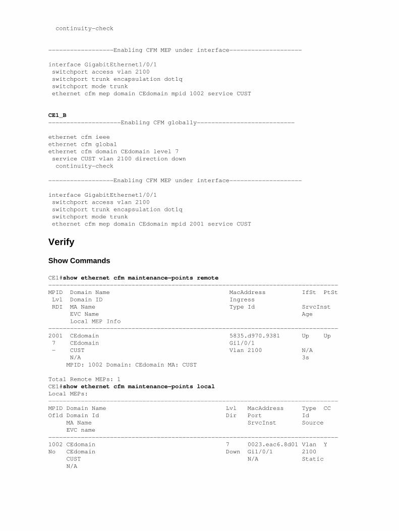
CE1#show ethernet cfm maintenance−points remote−−−−−−−−−−−−−−−−−−−−−−−−−−−−−−−−−−−−−−−−−−−−−−−−−−−−−−−−−−−−−−−−−−−−−−−−−−−−−−−−MPID Domain Name MacAddress IfSt PtSt Lvl Domain ID Ingress RDI MA Name Type Id SrvcInst EVC Name Age Local MEP Info−−−−−−−−−−−−−−−−−−−−−−−−−−−−−−−−−−−−−−−−−−−−−−−−−−−−−−−−−−−−−−−−−−−−−−−−−−−−−−−−2001 CEdomain 5835.d970.9381 Up Up 7 CEdomain Gi1/0/1 − CUST Vlan 2100 N/A N/A 3s MPID: 1002 Domain: CEdomain MA: CUST
Total Remote MEPs: 1CE1#show ethernet cfm maintenance−points localLocal MEPs:−−−−−−−−−−−−−−−−−−−−−−−−−−−−−−−−−−−−−−−−−−−−−−−−−−−−−−−−−−−−−−−−−−−−−−−−−−−−−−−−MPID Domain Name Lvl MacAddress Type CCOfld Domain Id Dir Port Id MA Name SrvcInst Source EVC name−−−−−−−−−−−−−−−−−−−−−−−−−−−−−−−−−−−−−−−−−−−−−−−−−−−−−−−−−−−−−−−−−−−−−−−−−−−−−−−−1002 CEdomain 7 0023.eac6.8d01 Vlan YNo CEdomain Down Gi1/0/1 2100 CUST N/A Static N/A

Verify Continuity Check
CE1#ping ethernet mpid 2001 domain CEdomain service CUST
Type escape sequence to abort.Sending 5 Ethernet CFM loopback messages to 5835.d970.9381, timeout is 5 seconds:!!!!!Success rate is 100 percent (5/5), round−trip min/avg/max = 1/1/1 ms
Total Local MEPs: 1Till now MIP is not configured on PE1 and PE3 hence output of show command and traceroute command will be as per below.
CE1#tracer ethernet mpid 2001 domain CEdomain service CUSTType escape sequence to abort. TTL 64. Linktrace Timeout is 5 secondsTracing the route to 5835.d970.9381 on Domain CEdomain, Level 7, vlan 2100Traceroute sent via Gi1/0/1
B = Intermediary Bridge! = Target Destination* = Per hop Timeout−−−−−−−−−−−−−−−−−−−−−−−−−−−−−−−−−−−−−−−−−−−−−−−−−−−−−−−−−−−−−−−−−−−−−−−−−−−−−−−− MAC Ingress Ingr Action Relay Action Hops Host Forwarded Egress Egr Action Previous Hop−−−−−−−−−−−−−−−−−−−−−−−−−−−−−−−−−−−−−−−−−−−−−−−−−−−−−−−−−−−−−−−−−−−−−−−−−−−−−−−−! 1 5835.d970.9381 Gi1/0/1 IngOk RlyHit:MEP Not Forwarded 0023.eac6.8d01
CE1_A can see CE1_B via traceroute.
Now, configure MIP on PE1 and PE2.
PE1:interface GigabitEthernet 4/2 service instance 2100 ethernet EVC_CE1 cfm mip level 7
PE2:interface GigabitEthernet 4/2 service instance 2100 ethernet EVC_CE1 cfm mip level 7
Now, check the traceroute results from CE1.
CE1#traceroute ethernet mpid 2001 domain CEdomain service CUSTType escape sequence to abort. TTL 64. Linktrace Timeout is 5 secondsTracing the route to 5835.d970.9381 on Domain CEdomain, Level 7, vlan 2100Traceroute sent via Gi1/0/1
B = Intermediary Bridge! = Target Destination* = Per hop Timeout
−−−−−−−−−−−−−−−−−−−−−−−−−−−−−−−−−−−−−−−−−−−−−−−−−−−−−−−−−−−−−−−−−−−−−−−−−−−−−−−− MAC Ingress Ingr Action Relay Action Hops Host Forwarded Egress Egr Action Previous Hop−−−−−−−−−−−−−−−−−−−−−−−−−−−−−−−−−−−−−−−−−−−−−−−−−−−−−−−−−−−−−−−−−−−−−−−−−−−−−−−−B 1 ccef.48d0.64b0 Gi4/2 IngOk RlyMPDB Forwarded 0023.eac6.8d01B 2 8843.e1df.00b0 RlyMPDB Forwarded Gi4/2 EgrOK ccef.48d0.64b0! 3 5835.d970.9381 Gi1/0/1 IngOk RlyHit:MEP Not Forwarded 8843.e1df.00b0

You should be able to see the difference in the traceroute output. Iintermediate hops are seen after MIPs onPE1 and PE2 are configured..
Debug Commands
debug ethernet cfm diagnostic packetsdebug ethernet cfm packets
Performance Management
Key Performance Indicators (KPIs)
Frame Loss Ratio − percentage (%) of service frames not delivered/total number of service framesdelivered in T time interval
•
Frame Delay − round−trip/one−way delay for a service frame• Frame Delay Variation − variation in frame delay between a pair of service frames•
Measuring KPIs
Frame Delay/Delay Variation
One−way or two−way measurements• Requires synthetic traffic with timestamps• Requires time−of−day synchronization for one−way delay•
Frame Loss
One−way Frame LossSource to Destination − Far−End♦ Destination to Source − Near−End♦
•
Service Frame Loss (actual loss) − requires counter exchangeApplicable only to Point−to−Point EVCs♦
•
Statistical Frame Loss − relies on synthetic traffic• Requires synthetic traffic for multipoint services
Applicable to Point−to−Point and Multipoint EVCs♦ •
Cisco Performanace Management Solution
Ethernet performance probes based on IEEE 802.1ag and vendor−specific PDUsMeasure one−way FD/FDV/FL and two−way FD/FDV♦ Partial multi−vendor network support♦ Configured and scheduled via IP SLA♦ Shipping under feature name: IP SLA for Metro Ethernet♦
•
Ethernet performance probes based on Y.1731 PDUs• Priority to these mechanisms in Cisco IOS®: One−way ETH−DM/Two−way ETH−DM,Single−ended ETH−LM and Cisco−proposed Y.1731 extensions (ETH−SLM) Multi−vendorinteroperability
•
Software and hardware−assisted implementation configured and scheduled via IP SLA• Phased−out delivery for selected Cisco IOS and Cisco IOS−XR platforms•

Usage Guidelines and Restrictions
Cisco 7600 Implementation• Y.1731 PM not supported for these CFM scenarios:♦
MEP on switchport◊ MEP on VPLS L2VFI◊ UP MEP on Service Instance with Bridge−Domain◊ DOWN MEP on untagged Service Instance with Bridge−Domain◊ DOWN MEP on doubled−tagged routed (sub)interface◊ Port MEP◊
After a Supervisor switchover, Y.1731 PM stats are cleared⋅ IPSLA restart required◊
Port−Channel considerations⋅ Member interfaces must reside on ES+ linecards◊ For Loss probes (LMM), all members must reside on the same NPU (restriction doesnot apply to Delay probes)
◊
Adding/deleting a member link renders the session invalid◊ Y.1731 PM not supported on Port−Channel with manual EVC load balancing◊ Y.1731 PM not supported on mLACP◊
Prerequisites
Configure CFM.MD, MA, and MEPs♦
•
Enable distribution of local MEP configuration to ES+ linecards.Program hardware to respond to incoming Delay Measurement Message (DMM)/LossMeasurement Message (LMM) PDUs
♦
Router(config)#ethernet cfm distribution enable♦
•
(Optional) Configure time source protocol (NTP or PTPv2). Required for one−way delaymeasurement.
•
Enable synchronization down to the linecard.Router(config)#platform time−source♦
•
(Optional) Enable service frame per−cos/aggregate counter monitoring under CFM MEP. Requiredfor loss probes.
Router(config−if−srv−ecfm−mep)#monitor loss counter♦
•
Configuration Management
The previous commands have already been enabled in Fault Management, therefore just IP SLA is enabled tostart with Performance Management.
Ip sla 10 Ethernet y1731 loss LMM domain SPdomain evc EVC_CE1 mpid 201 cos 8 source mpid 102 Frame interval 100 Aggregate interval 180
Ip sla schedule 10 start−time after 00:00:30 life forever.
Verify
PE1#show ip sla stat 10IPSLAs Latest Operation Statistics
IPSLA operation id: 10Loss Statistics for Y1731 Operation 10Type of operation: Y1731 Loss Measurement

Latest operation start time: 09:30:11.332 UTC Fri Dec 20 2013Latest operation return code: OKDistribution Statistics:
Interval Start time: 09:30:11.332 UTC Fri Dec 20 2013 Elapsed time: 56 seconds Number of measurements initiated: 120 Number of measurements completed: 120 Flag: OK
PE1#show ethernet cfm pm session activeDisplay of Active Session−−−−−−−−−−−−−−−−−−−−−−−−−−−−−−−−−−−−−−−−−−−−−−−−−−−−−−−−−−−−−−−−−−−−−−−−−−−−EPM−ID SLA−ID Lvl/Type/ID/Cos/Dir Src−Mac−address Dst−Mac−address−−−−−−−−−−−−−−−−−−−−−−−−−−−−−−−−−−−−−−−−−−−−−−−−−−−−−−−−−−−−−−−−−−−−−−−−−−−− 0 10 5/XCON/N/A/7/Up ccef.48d0.64b0 8843.e1df.00b0Total number of Active Session: 1
−−> Src−Mac−address: SRC MAC of MEP,check 'show ethernet cfm maintenance−points local'−−> Dst−Mac−address: MAC of dest MEP,check 'show ethernet cfm maintenance−points remote'
PE1#show ethernet cfm pm session detail 0Session ID: 0Sla Session ID: 10Level: 5Service Type: XCOService Id: N/ADirection: UpSource Mac: ccef.48d0.64b0Destination Mac: 8843.e1df.00b0Session Status: ActiveMPID: 102Tx active: yesRx active: yesTimeout timer: stoppedLast clearing of counters: 08:54:20.079 UTC Sat Dec 20 2013DMMs:Transmitted: 0DMRs:Rcvd: 01DMs:Transmitted: 0Rcvd: 0LMMs:Transmitted: 3143161LMRsRcvd: 515720VSMs: Transmitted: 0VSRs: Rcvd: 0
Debug Commands
debug ip sla trace <oper_id>debug ip sla error <oper_id
Related Information
ITU−T Y.1731M Performance Monitoring• Cisco Carrier Ethernet OAM Overview• Technical Support & Documentation − Cisco Systems•

Updated: Apr 09, 2014 Document ID: 117457