Embed Size (px)
Citation preview
Ethernet Communication in Lighting Control
Shaun Jackman
April 27, 2005
A thesis submitted in partial fulfillment
of the requirements for the degree of
Bachelor of Applied Science
in the school of
Engineering Science,
Simon Fraser University
Copyright 2005 Shaun Jackman. All rights reserved.


APPROVAL
Name: Shaun Jackman
Degree: Bachelor of Applied Science
Title of thesis: Ethernet Communication in Lighting Control
Dr. Mehrdad SaifDirector, School of Engineering Science, SFU
Examining Committee:
Dr. M. ParameswaranProfessor, Engineering Science, SFUAcademic Advisor
D. HigginsPresident, Pathway Connectivity Inc.Technical Advisor
B. BartLecturer, Computing Science, SFUCommittee Member
Date Approved:


Abstract
Pathway Connectivity Inc. designs products to control entertainment and architec-
tural lighting devices. Their products are typically installed in theatres, theme parks,
and cruise ships. Lighting control devices currently use an industry standard pro-
tocol, DMX512, or digital multiplex 512, which allows 512 lighting fixtures to be
controlled using a single cable. With the advent of more complex lighting fixtures,
such as moving lights, this aging protocol is becoming less suitable. During my employ
at Pathway Connectivity, the company designed the Pathport to serve as a bridge
between the installed base of DMX products and today’s ubiquitous Ethernet net-
works. This thesis considers the design of the Pathport and measures a number of
performance parameters such as network latency, dropped packet rate, and processor
utilisation.
i

Acknowledgements
I would like to thank my technical advisor, Dave Higgins, for providing a workplace
that fosters exploration and innovation.
I would like to thank my supervisors, Dr. Ash Parameswaran and Brad Bart, for
their direction throughout the writing of this thesis, as well as my past supervisors,
Dr. Patrick Leung, and Dr. Jacques Vaisey for their help in writing the proposal. Dr.
Vaisey was an enthusiastic and thoughtful professor. I regret that future engineering
students will not have the experience of knowing him.
Finally, I would like to thank my family and friends for their company, my parents,
Mike and Agnes Jackman, for providing encouragement in any endeavour I undertook,
and my girlfriend, Breanne De Jaegher, for her scrupulous editing, excellent cooking,
companionship, and support.
ii

Contents
List of Tables v
List of Figures v
List of Acronyms vi
Glossary x
1 Purpose 1
2 Background 1
3 Objectives 2
3.1 Functional Specification . . . . . . . . . . . . . . . . . . . . . . . . . 3
3.2 Design and Implementation . . . . . . . . . . . . . . . . . . . . . . . 4
3.3 Testing . . . . . . . . . . . . . . . . . . . . . . . . . . . . . . . . . . . 5
4 Design 5
4.1 Communications . . . . . . . . . . . . . . . . . . . . . . . . . . . . . 5
4.2 User Interface . . . . . . . . . . . . . . . . . . . . . . . . . . . . . . . 10
4.3 Lighting Control . . . . . . . . . . . . . . . . . . . . . . . . . . . . . 11
4.4 Hardware . . . . . . . . . . . . . . . . . . . . . . . . . . . . . . . . . 12
5 Simulation 13
5.1 Firmware . . . . . . . . . . . . . . . . . . . . . . . . . . . . . . . . . 14
iii

5.2 Drivers . . . . . . . . . . . . . . . . . . . . . . . . . . . . . . . . . . . 15
6 Experiment #1: Delay 17
6.1 Procedure . . . . . . . . . . . . . . . . . . . . . . . . . . . . . . . . . 17
6.2 Observation . . . . . . . . . . . . . . . . . . . . . . . . . . . . . . . . 19
6.3 Analysis . . . . . . . . . . . . . . . . . . . . . . . . . . . . . . . . . . 20
7 Experiment #2: Dropped Packet Rate 22
7.1 Procedure . . . . . . . . . . . . . . . . . . . . . . . . . . . . . . . . . 22
7.2 Observation . . . . . . . . . . . . . . . . . . . . . . . . . . . . . . . . 23
7.3 Analysis . . . . . . . . . . . . . . . . . . . . . . . . . . . . . . . . . . 23
8 Experiment #3: Processor Use while Merging 25
8.1 Procedure . . . . . . . . . . . . . . . . . . . . . . . . . . . . . . . . . 25
8.2 Observation . . . . . . . . . . . . . . . . . . . . . . . . . . . . . . . . 25
8.3 Analysis . . . . . . . . . . . . . . . . . . . . . . . . . . . . . . . . . . 27
9 Conclusions 27
References 28
iv

List of Tables
1 Communication requirements . . . . . . . . . . . . . . . . . . . . . . 7
2 Simulated low-level drivers . . . . . . . . . . . . . . . . . . . . . . . . 15
List of Figures
1 An example of a lighting control network . . . . . . . . . . . . . . . . 6
2 Hardware components . . . . . . . . . . . . . . . . . . . . . . . . . . 12
3 dmx4linux – lighting console and DMX display . . . . . . . . . . . . . 13
4 Firmware organisation . . . . . . . . . . . . . . . . . . . . . . . . . . 15
5 Measuring zero delay using a loopback cable . . . . . . . . . . . . . . 18
6 Measuring a calibrated non-zero delay using a delay line . . . . . . . 19
7 Measuring the delay of the Pathport system . . . . . . . . . . . . . . 19
8 Delay vs. time of a “one input, one output” network . . . . . . . . . 20
9 Histogram of a single period . . . . . . . . . . . . . . . . . . . . . . . 21
10 Processor utilisation and dropped packet rate vs. packets per second 24
11 House-keeping cycles vs. number of merged channels . . . . . . . . . 26
12 Processor utilisation vs. number of merged channels . . . . . . . . . . 26
v

List of Acronyms
ACN . . . . . . . . . . Architecture for Control Networks – An ESTA standard for
the configuration and control of TCP/IP based lighting control net-
works.
ANSI . . . . . . . . . American National Standards Institute – An American or-
ganization responsible for a variety of voluntary standards, including
computer and communication standards.
bps . . . . . . . . . . . bits per second – A measure of data rate.
BSD . . . . . . . . . . Berkeley System Distribution – A distribution of Unix origi-
nally written by Bill Joy and others at the University of California,
Berkeley.
CAT5 . . . . . . . . . Category 5 Cable – The standard cable used in wiring Ethernet
installations. It has four pairs of conductors, only two of which are
used in 10BaseT and 100BaseT.
DC . . . . . . . . . . . . Direct Current – Voltage constant over time.
DHCP . . . . . . . . dynamic host configuration protocol – A protocol for the
automatic configuration of TCP/IP networks. See also RFC1533.
DMX512 . . . . . Digital Multiplex – A unidirectional 250 kbps, 8 bit frame, 512
byte packet, streaming serial protocol used in the lighting industry to
control lighting dimmers and fixtures. Uses EIA-485 for the physical
medium. Originally designed by USITT, this standard is currently
maintained by ESTA. Also referred to simply as DMX.
EIA . . . . . . . . . . . Electronic Industries Alliance – A partnership of US high-tech
associations and companies that maintains standards for electronics.
See also TIA.
EIA-485 . . . . . . Electronic Industries Alliance standard number 485 – A
physical communication standard used in multi-drop serial protocols
vi

consisting of two differential signals that swing between 0V and 5V.
Previously known as RS485. Maintained by the EIA.
EL . . . . . . . . . . . . electroluminescent – An organic phosporescent used to back-
light LCD displays.
ESTA . . . . . . . . . Entertainment Services and Technology Association – ESTA
is a non-profit trade association representing the North American
entertainment technology industry.
GDB . . . . . . . . . GNU debugger – A debugger written by the GNU project.
GNU . . . . . . . . . GNU’s not Unix – The Free Software Foundation’s project to
provide a freely distributable replacement for Unix.
GTK+ . . . . . . . GUI toolkit – A library for designing portable graphical user
interfaces.
HTP . . . . . . . . . . highest takes precedence – A DMX merge scheme wherein the
controller giving the highest control values takes precedence.
IEEE . . . . . . . . . Institute of Electrical and Electronics Engineers – An in-
dustry organisation that maintains a number of electrical standards,
such as PoE and Wi-Fi.
IETF . . . . . . . . . Internet Engineering Task Force – An open international
community of network engineers that maintains a number of net-
working standards.
IGMP . . . . . . . . internet group management protocol – Used to control which
multicast groups Ethernet switches route to which subnets.
IP . . . . . . . . . . . . . Internet protocol – The standard protocol used for communi-
cation on the Internet. See also STD5 (RFC791).
IrDA . . . . . . . . . Infrared Data Association – A protocol suite used in wireless
infrared communication. It is often used between hand-held com-
puters. The Pathport uses a SIR transceiver module.
vii

JTAG . . . . . . . . . Joint Test Action Group – A standard for testing silicon cores,
often used for debuggging with micro-controllers.
kbps . . . . . . . . . . kilobits per second – A measure of data rate.
LCD . . . . . . . . . . liquid crystal display – A thin flat display capable of displaying
text and graphics to a user, as used in a graphing calculator or hand-
held computer, for example.
LTP . . . . . . . . . . last takes precedence – A DMX merge scheme in which the
most recent change in control value takes precedence.
Mbps . . . . . . . . . megabits per second – A measure of data rate.
PC . . . . . . . . . . . . personal computer – In the context of this project, a PC is
used to configure the Pathport, communicating using Ethernet.
PoE . . . . . . . . . . . Power over Ethernet – 48 V DC delivered over either the trans-
former midspan or one of CAT5 cabling’s two spare pairs of wires.
This technology was originally developed by the VoIP industry, who
use it to power VoIP handsets. It is now a standard maintained by
the IEEE, namely IEEE802.3af.
RDM . . . . . . . . . remote device management – The extension of DMX to a
bidirectional communication protocol.
RFC . . . . . . . . . . request for comments – A body of standards governing the
functioning of the Internet published by the IETF.
RFU . . . . . . . . . . remote focus unit – A portable hand-held console used for test-
ing and focusing lighting fixtures.
ROM . . . . . . . . . read-only memory – This term is now also used to describe
flash memory, which is writable in large time scales.
SIR . . . . . . . . . . . serial infrared – Supports asynchronous communication at 9600
bps through 115.2 kbps at distances of up to one metre.
STD . . . . . . . . . . Internet standard – A set of RFC documents that have been
adopted by the IETF as official Internet standards.
viii

TAP . . . . . . . . . . virtual Ethernet interface – A simulated Ethernet interface
for Unix systems.
TCP . . . . . . . . . . transmission control protocol – An Internet protocol that pro-
vides a full-duplex streamed communication channel. See also STD7
(RFC793).
TCP/IP . . . . . . transmission control protocol / Internet protocol – The
suite of protocols that powers the Internet.
TDM . . . . . . . . . time division multiplexing – A mutiplexing scheme wherein
multiple communication channels share the same medium by allo-
cating a different time slot to each channel.
TFTP . . . . . . . . trivial file transfer protocol – A simple file transfer protocol
often used for downloading boot code and firmware. See also STD33
(RFC1350).
TIA . . . . . . . . . . . Telecommunication Industries Association – An association
of companies in the telecommunications industry. See also EIA.
UART . . . . . . . . Universal Asynchronous Receiver/Transmitter – A device
used for asynchronous serial communication.
UDP . . . . . . . . . . user datagram protocol – An Internet protocol that provides a
full-duplex packet oriented communication channel. See also STD6
(RFC768).
USITT . . . . . . . United States Institute for Theatre Technology – The orig-
inal authors of the DMX standard, which is now being maintained
by ESTA.
VoIP . . . . . . . . . . voice over Internet protocol – A standard for transmitting
voice communication over the Internet.
Wi-Fi . . . . . . . . . wireless fidelity – Wireless communnication standard also known
as wireless Ethernet or IEEE802.11.
ix
Glossary
100BaseT – The extension of 10BaseT to a 100 Mbps connection.
10BaseT – The physical communication standard used in 10 Mbps Ethernet.
channel – A single channel controls a single parameter of a fixture, such as its
brightness. A single channel is eight bits wide. Parameters that require more
precision, such as the position of a moving light, may use two or more channels.
console – A lighting console which controls fixtures using DMX, also called a control
desk.
Debian – A Unix implementation most commonly using the Linux kernel.
Ethernet – A network technology for local area networks. Two common flavours
are 10BaseT and 100BaseT.
fixture – An intelligent lighting fixture controlled by DMX. A number of other de-
vices are also controlled using DMX, such as lighting dimmers, fog machines,
and relays.
half-duplex – A bidirectional communication channel in which only one node can
transmit at a time.
hand-held – A hand-held computer, such as a Palm or Pocket PC.
Linux – A Unix kernel originally created by Linus Torvalds. It is now a world-wide
project with thousands of authors.
multicast – A point-to-multipoint TCP/IP protocol. Multicast groups are negoti-
ated using IGMP and data is transported using UDP. See also STD5 (RFC1112).
non-volatile – Used to describe a memory device that retains its contents without
power.
Pathport – A DMX / Ethernet network gateway device, and the focus of this paper.
x

Pathway Connectivity Inc. – A data communications company in the entertain-
ment lighting industry developing the Pathport.
segment – A portion of a lighting network that shares the same DMX universe. See
also universe.
universe – One segment of a DMX network is referred to as a universe. Each universe
carries 512 8-bit control channels, sourced by the lighting console, and multiple
lighting fixtures controlled by these channels. See also channel.
Unix – An operating system developed at Bell Labs, originally spelled UNIX. This
term, spelled Unix, now generally connotes a large class of systems implementing
the same interface, such as Linux and BSD.
xi

1 Purpose
For the past decade, communication between lighting equipment has been achieved
using DMX512 (Digital Multiplex), an industry standard serial protocol. However,
the industry is beginning to shift from the ageing DMX protocol towards Ethernet
as the new communication standard.
The purpose of this project is to design, implement and test the Pathport, a device
meant to act as the bridge between the installed base of DMX products and newer
Ethernet products. The device multiplexes multiple 250 kbps DMX signals onto one
10 Mbps Ethernet network. A second Pathport then extracts the component DMX
signals from the Ethernet network to control lighting fixtures.
2 Background
Pathway Connectivity Inc. [1] is a small company of roughly a dozen employees op-
erating in a unique market: the entertainment and architectural lighting industry.
Specifically, the company designs and markets products that transport and aid com-
munication between lighting consoles (the controlling devices), and intelligent lighting
fixtures (the controlled devices). Typical installations are in theatres, theme parks,
and cruise ships. Pathway does not design the consoles or the fixtures themselves.
Rather, the company concentrates on the devices in the middle of the lighting net-
work that facilitate communication, the equivalent of switches and routers in Ethernet
networks.
Lighting control communication primarily uses an industry specific serial protocol
named DMX [2], which has been in existence and left relatively unchanged for al-
most twenty years. A large portion of Pathway’s business comes from a commodity
product, the DMX Repeater. This device is to DMX what a hub is to Ethernet,
allowing a single signal to drive multiple outputs. Modern networking technologies
are revolutionising this market by replacing DMX and its unique wire with Ethernet
and CAT5 (Category 5 Cable). This substitution allows a more costly DMX repeater
to be replaced by a fifty dollar Ethernet hub.
1
Although the market for a product such as the DMX Repeater might be depressed
after the industry’s transition to Ethernet, the business opportunity that arises is
the same as in any major tech-industry paradigm shift. The existing DMX hardware
in the field will need to communicate with the new Ethernet hardware. Protocol
converters and repeaters have previously been Pathway’s niche led to the design of a
new product to fill the apparent gap in the market, the Pathport. Its purpose is to
act as a communication gateway between DMX segments and an Ethernet network,
allowing existing equipment to interoperate with modern gear.
3 Objectives
During my first work term at Pathway Connectivity, my technical advisor challenged
me to build a device that translated lighting data from DMX to an Ethernet network.
This device was to be the proof of concept for a product that would eventually become
the Pathport. I built this proof of concept using a standard PC (personal computer)
running Linux, a wire-wrap DMX card, and an off the shelf network card. The primary
goal of this thesis is to design and build the Pathport, whose primary purpose is not
drastically different from the original proof of concept. In fact, the first prototype
Pathport was referred to as the “shrink-ray” model, since it used hardware quite
similar to a PC but much reduced in size. The architecture of the final product
evolved much from the original “shrink-ray” prototype. Its design is discussed in this
paper.
The second goal of this thesis is to design a suite of tests that show the Pathport meets
certain performance goals outlined in the functional specification, which follows. The
experimental evidence is given in the final sections of this paper.
2

3.1 Functional Specification
The functional requirements of the Pathport define the capability, performance, and
capacity of the system and are broken up into three major components:
Communications — Pathport-to-device communication
User Interface — Pathport-to-user communication
Lighting Control — DMX and lighting control algorithms
To be a useful and successful product, the Pathport must have the following capabil-
ities:
1. Communication Requirements
(a) Transmit or receive on two DMX ports simultaneously.
(b) Receive DMX control data from a console.
(c) Control a fixture using DMX.
(d) Discover, configure, and receive status information from a fixture using
RDM (remote device management).
(e) Communicate with lighting control devices using ACN (Architecture for
Control Networks).
(f) Communicate using 10 Mbps (megabits per second) Ethernet.
(g) Communicate using TCP/IP (transmission control protocol / Internet pro-
tocol).
(h) Communicate using 9600 bps (bits per second) IrDA (Infrared Data Asso-
ciation).
3

2. User Interface Requirements
(a) Display status information using a graphical LCD (liquid crystal display).
(b) Be remotely configurable by a PC connected to the network using TCP/IP.
(c) Be configurable by a hand-held device using IrDA.
(d) Store the device configuration in non-volatile memory so that the device
can resume from power failure autonomously.
3. Lighting Control Requirements
(a) Process 1000 DMX packets per second.
(b) Achieve end-to-end packet latency of no more than 30 ms.
(c) Drop no more than 0.1% packets under a load of 1000 packets per second.
(d) Patch a DMX channel from any input to any output.
(e) Allow multiple consoles to control a single fixture, through either HTP
(highest takes precedence), LTP (last takes precedence), or priority patch-
ing.
(f) Merge up to 8 separate channels.
Ethernet is a best-effort transmission medium and performs best when it is operating
below 60% of its maximum capacity. The figure of 1000 packets per second approaches
this guideline. The lighting network as a whole must be capable of processing 1000
DMX packets per second, whereas an individual output node must be capable of
merging eight individual channels of DMX.
3.2 Design and Implementation
The majority of the design work for the Pathport was completed during a four month
work term, which was eventually extended to a full year. Although I was heavily
involved in the hardware design process before the hardware existed, the majority of
my work consisted of writing the firmware for the Pathport. This thesis discusses the
communication protocols mandated by the functional specification and looks at the
selection of hardware components to make this communication possible. My work
4

also included simulating a Pathport – and in fact many Pathports – to facilitate
testing. Finally, following the completion of the Pathport hardware and its firmware,
my work consisted of implementing test benches to measure the performance metrics
mandated by the functional specification.
3.3 Testing
Ensuring the device meets the functional requirements outlined in Section 3.1 is the
basis for validating the project. The experiments concentrate on testing the net-
work performance and reliability of the system. Physical tests, such as lifetime and
reliability due to physical failure, are outside the scope of this project.
In Experiment #1, the additional delay introduced by the Pathport in a nominal
lighting network is measured. This result is compared to the functional requirement
in Section 3.1. In Experiment #2, the rate of dropped packets is compared against
network activity to determine the maximum load of the system. In Experiment #3,
the Pathport’s processor utilisation is compared against the processor intensive task of
merging DMX, discussed in 4.3, to determine the maximum number of DMX channels
a Pathport is capable of merging.
4 Design
4.1 Communications
The Pathport must communicate with the devices listed in Table 1. An example
network of these devices is shown in Figure 1. Implementing the protocols needed
to communicate with each of these devices was a large part of this project. These
protocols use three separate physical media and each require a unique piece of com-
munication hardware.
TCP/IP is the protocol suite commonly used to communicate over Ethernet. TCP/IP
is needed for communication between the Pathport and the user’s computer, which is
used to configure the Pathport remotely. Since TCP/IP is a suite of communication
5

Key
WiFi Access Point
PathportComputer
Lamp PDA
Lighting Console
DMX
IrDA
WiFi
DMX
DMX DMX
Ethernet
Figure 1: An example of a lighting control network
6

Table 1: Communication requirements
Device Protocol Purpose
PathportTCP/IP (transmission control pro-tocol / Internet protocol)
Transmission of multiplexed DMXcontrol data between Pathports.
ACN (Architecture for Control Net-works)
Lighting network management.
PCTCP/IP (transmission control pro-tocol / Internet protocol)
Configuration of the Pathport bythe user’s PC.
Hand-heldIrDA (Infrared Data Association)
Configuration of the Pathport bythe user at close range.
LightingConsole DMX512 (Digital Multiplex)
Source of DMX control data.
LightingFixture DMX512 (Digital Multiplex)
Lighting control.
RDM (remote device management)Configuration of the fixture andstatus feedback from the fixture.
protocols, a variety of protocols are implemented, such as DHCP (dynamic host con-
figuration protocol) for network configuration and multicast for point-to-multipoint
communication. TCP/IP is also used to transmit lighting control data between Path-
ports.
The medium used to transmit TCP/IP is typically Ethernet. Thus, the Pathport re-
quires an Ethernet chip. Ethernet commonly comes in two flavours: 10 Mbps and 100
Mbps. Working with 100 Mbps requires a significantly more powerful processor and
thus higher frequencies on the circuit board. The Pathport is designed around the
assumption that 10 Mbps is sufficient for the transport of lighting data in a typical
installation. A quick back-of-the-envelope calculation shows that a theoretical maxi-
mum of 40 250-kbps DMX channels can be multiplexed onto one 10 Mbps Ethernet
channel.
nDMX/Ethernet =fEthernet
fDMX
=10 Mb/s
250 kb/s= 40 (1)
7

This capacity is more than sufficient for the largest existing lighting installations.
Robustness is also important to the lighting industry, and because of its slower speed,
10 Mbps Ethernet tends to operate with fewer errors in marginal conditions than 100
Mbps Ethernet.
ACN [3] is an emerging ANSI (American National Standards Institute) protocol for
the control of TCP/IP based lighting control networks currently under development
by ESTA (Entertainment Services and Technology Association). The purpose of this
protocol is to standardise the communication of modern lighting control networks,
much the way DMX did for serial-based lighting devices. ACN’s only requirement of
the hardware is that it be capable of communicating using TCP/IP, the underlying
protocol on which ACN is transported.
Although ACN has been in development for many years now, the standard has not
yet reached an implementable stage. In the mean time, Pathway developed a propri-
etary protocol for the configuration and control of lighting networks using Ethernet.
This protocol is referred to simply as the Pathport Protocol. Like ACN, Pathway’s
proprietary protocol uses TCP/IP to communicate using Ethernet. Therefore, the
Pathport requires an Ethernet chip and a TCP/IP stack. These requirements also
leave open the possibility of implementing ACN in the future.
IrDA [4] is the protocol suite used in wireless infrared communication. Since the
Pathport does not have a physical user-input device, a hand-held device may be used
to configure the Pathport at close proximity. The data passed in this process is not
high in volume. Minimum speed IrDA, 9600 bps, is sufficient and minimises complex-
ity and cost. The Pathport requires an IrDA capable UART (Universal Asynchronous
Receiver/Transmitter), and an infrared diode and lens to transmit and receive the
IrDA data.
DMX is the standard protocol used in entertainment lighting control. DMX is a rel-
atively straightforward 250 kbps (kilobits per second) serial protocol. At the physical
level, it uses EIA-485 (Electronic Industries Alliance standard number 485), a differ-
ential signal electrical standard, over any twisted pair cable, often Belden cable or
more recently CAT5. DMX is a multi-drop bus with one master, the lighting console,
controlling many slaves, the lighting fixtures. The console is the only device on the
bus that may transmit packets; the fixtures listen passively.
8

A full DMX packet consists of 512 individual lighting levels. Each level consists of
eight bits of data and three overhead bits for eleven bits in total, and is commonly
referred to as a frame of DMX. The overhead bits consist of two start bits, no parity
bits, and one stop bit. Their purpose is to synchronise the transmitting and receiving
UARTs since an explicit clock is not transmitted. This configuration is commonly
referred to as 8N2 asynchronous serial data. At 250 kbps, each bit takes 4 µs to
transmit and a frame takes 44 µs to transmit.
tframe =nbit/frame
fbit
=11 bit
250 kbit/s= 44 µs (2)
To reduce the overall cost per DMX port to the user, each Pathport unit has two DMX
ports, and so the micro-controller must have sufficient processing power to receive two
simultaneous streams of DMX. It must be capable of processing two frames of DMX
data every 44 µs. This requirement is more stringent than receiving one frame every
22 µs since one frame from each port could potentially arrive nearly simultaneously.
To physically receive the DMX signal, the Pathport requires two UARTs, one for each
DMX port.
A complete frame of DMX also includes an additional frame, referred to as the start
code, transmitted before the 512 lighting levels. This start code frame is set to zero
to indicate the following frames compose lighting control data. If the start code is
non-zero, the following data is vendor specific. Non-zero start codes are commonly
used to configure lighting fixtures, receive status reports, and is employed by RDM
to accomplish these same tasks.
RDM is the extension of DMX to a bidirectional protocol. RDM is an evolving
standard being developed by ESTA [5] for the intelligent control of lighting fixtures.
With bidirectional communication, lighting fixtures can identify themselves and their
capabilities, be remotely configured, and send back status information. Although
lighting communication networks were typically configured by hand previously, RDM
allows these networks to be self-configuring and intelligent.
RDM uses the same physical medium as DMX. However, it is a half-duplex protocol
that requires that the device be able to both send and receive data on the same
9

physical wire. Therefore, the Pathport must be able to dynamically swap between
transmitting to and receiving from that single wire.
4.2 User Interface
The Pathport is not intended to have a direct physical user interface. Since these
devices are expected to be used in quantity, physically manipulating each device to
configure them would be time consuming. Eliminating physical controls also has the
advantage of reducing part cost and wear-and-tear of the device itself. There are
three ways in which the user interacts with the device:
• Remote configuration using a PC
• Local configuration using a wireless hand-held device
• LCD for status display
Remote Configuration — The Pathport is typically configured from a computer
that communicates with the Pathport using its Ethernet connection. This configu-
ration is often changed relatively rarely; the Pathport may be reconfigured one or
more times per show, or even just once per installation. The Pathport stores this
configuration in its non-volatile flash memory and is autonomous from then on. The
configuring computer does not need to run during normal operation of the Pathport.
Local Configuration — Although the majority of the user’s interaction with this
device is intended to be remote, the user may find the need to configure the Pathport
when he or she is much closer to the device itself than to the controlling workstation,
for example when connecting lighting fixtures in the ceiling of a theatre. To meet this
need, the user can employ a hand-held computing device to configure the Pathport
using the infrared port, rather than climbing down the ladder and walking to the
control booth.
LCD — The user can get quick status information from the front panel of the
Pathport, such as which DMX ports are actively transmitting or receiving data. To
facilitate this, the Pathport requires a small graphical LCD.
10

4.3 Lighting Control
Besides the basic transport of DMX over Ethernet, the Pathport can provide certain
application-specific control of the lighting fixtures. For example, the ability to control
one fixture with multiple lighting consoles is a common need of lighting designers.
DMX has no allowance for multiple controllers, so this functionality must be provided
at a higher level, specifically by the Pathport.
Patching allows multiple lighting consoles to control multiple independent segments
of DMX. A simple system of DMX devices contains one lighting console and many
lighting fixtures, all connected by one DMX segment. If there are more lighting
fixtures than may be controlled by one segment of DMX, the fixtures may be parti-
tioned across multiple segments of DMX. In addition, a complex system may contain
multiple lighting consoles, which generate multiple DMX signals. In this case, the
Pathport must act as a switch, routing DMX data from multiple input segments of
DMX to multiple output segments. This is referred to as patching DMX channels.
Merging allows multiple consoles to control one fixture. It is not uncommon for a
building to have a primary lighting console and backup console in case the primary
fails, as well as a portable hand-held console, called a RFU (remote focus unit), used
for testing and focusing lighting fixtures. Many systems also incorporate simplified
push-button controls, resembling household light switches, for use by non-technical
staff. The merge algorithm decides which of these devices controls the lighting fixture.
There are three common methods of merging DMX channels:
HTP (highest takes precedence) — The controller transmitting the highest, or
brightest, value takes control of the fixture.
LTP (last takes precedence) — The controller that executes the most recent change
takes control of the fixture.
Priority — One particular console is given total priority. If that console ceases to
transmit, a backup console assumes control of the fixture.
11

4.4 Hardware
In the communication requirements of Section 4.1 we noted a number of necessary
components. These components were incorporated on a pair of four-layer circuit
boards housed in a cast aluminium enclosure. The architecture of the Pathport
hardware and topology of these components is shown in Figure 2.
CS8900A
ST16C650A
Ethernet
UART
UART
UART
1 MBSRAM
Pathport
IrDA
10BaseT
DMX
DMX
Atmel AT91M40800
LCDSED1520
16 bit bus
32 MHz
ARM7TDMICPU
Timer CounterInterrupt Controller
Peripherals
2 MBFlash
Figure 2: Hardware components
The device is powered using PoE (Power over Ethernet), which is 48 V DC (Direct
Current) delivered on the Ethernet cable, eliminating the need for a second cable
solely for power.
12

5 Simulation
I did not have the benefit of a full lab of lighting equipment available to me for my
research. This situation prompted me to consider using a computer to simulate the
lighting hardware that I was lacking. I decided to port the Pathport firmware to run
on a Unix platform, specifically the Debian distribution of Linux.
The lighting hardware, such as consoles and fixtures, were simulated using the dmx4linux
[6] software package. It provides a software lighting console that uses graphical sliders
rather than physical sliders, as well as an application that displays the DMX levels a
lighting fixture would receive, as can be seen in Figure 3.
Figure 3: dmx4linux – lighting console and DMX display
Running the Pathport firmware on a full computer system has many prospective
advantages. A debugger, such as GDB (GNU debugger), can be used to inspect the
Pathport firmware process as it runs. This is possible to some extent on an embedded
system by using a JTAG (Joint Test Action Group) debugger. Due to cost constraints,
I did not have this equipment available to me. However, the foremost advantage was
the ability to simulate a rack of Pathports using only a single computer. Those
simulated Pathports could then saturate the Ethernet connection with traffic so that
13

a physical Pathport could see a variety of network conditions without the need for a
small fortune in lighting gear.
The Pathport hardware is not simulated in its entirety. In particular, the Pathport’s
RISC processor is not emulated; the firmware is recompiled for the host system and
runs natively on it. However, the Pathport’s hardware peripherals are simulated
using desktop computer counterparts. For example, the Pathport’s LCD is simulated
using a window on the host’s desktop. The simulation of the peripherals is discussed
further in Section 5.2.
5.1 Firmware
The Pathport firmware is divided up into three categories:
• platform dependent drivers
• platform independent libraries
• applications
The platform dependent drivers, such as the Ethernet interface, were rewritten for
the Unix platform. The platform independent libraries, such as the IrDA library, ran
without any or only minor modification. Finally, the applications make use of all the
libraries to comprise the entire system. This hierarchy can be seen in Figure 4.
Note there are exactly two applications: the loader and the firmware. The firmware
is field-upgradable by downloading new code to the device using TFTP (trivial file
transfer protocol). If the new firmware were faulty, or something were to go wrong
when writing the new firmware to flash ROM (read-only memory), the device could
be rendered useless. To help prevent this scenario, a division between the loader and
the firmware is created.
The loader’s responsibilities are kept to a minimum. It obtains an IP (Internet pro-
tocol) address from the DHCP server and checks for a firmware upgrade from the
TFTP server. If such an upgrade is available, it downloads the firmware and writes
it to the flash ROM. The loader, however, is not overwritten. Thus, even if the new
firmware were faulty or if the flash were to fail, the loader would still function; the
device can still reboot and attempt to download replacement firmware.
14

Platformdependent
LCD
DMX
SIR
Ethernet
Flash
IrDA
TCP/IP
Lighting
DHCP
TFTP
Libraries
Firmware
Loader
Applications
Figure 4: Firmware organisation
5.2 Drivers
To simulate the Pathport, each of the low-level drivers shown in Table 2 was rewritten
for the Unix platform.
Table 2: Simulated low-level drivers
Driver Simulation
DMX Simulated using shared memory.Ethernet Simulated using TAP (virtual Eth-
ernet interface).Flash Simulated using a file.IrDA Simulated using a TCP (transmis-
sion control protocol) socket.LCD Simulated using GTK+ (GUI
toolkit).
15

DMX — In essence, DMX simulates a 512-byte buffer of shared memory. In
fact, this is how it is often implemented. The protocol is not analysed as a stream
of packets like other communication protocols. Instead, it is viewed as a single 512-
byte buffer that is continually being updated by the master. Thus, the most sensible
simulation is not a socket or stream, but a 512-byte shared memory buffer. This also
allows interoperability with other pieces of Unix software that view a DMX buffer in
the same way, such as dmx4linux.
Ethernet — The Unix platform uses the standard Berkeley sockets [7] TCP/IP
interface. Our adapted TCP/IP stack, on the other hand, uses an entirely different
interface. Thus, the network protocol libraries, such as DHCP and TFTP could
not compile for Unix directly, and modifying them for the BSD (Berkeley System
Distribution) interface would defeat the purpose of simulating the system, as it would
then be using the host’s TCP/IP interface instead of the firmware’s, which needs the
testing. Instead, Linux’s virtual Ethernet interface, TAP, was used to simulate an
Ethernet interface. The host routes packets to and from this interface as if it were a
physical interface connected directly to a single physical device. In fact, the Ethernet
interface is virtual, and the connected device is the simulated Pathport running as a
process on the host system.
Flash — Flash ROM is used for non-volatile storage on the device. It is used
to store the firmware the device is running as well as permanent configuration data
such as serial numbers, networking information, and lighting control patches. This
non-volatile storage is easily simulated as a file on the host’s file-system.
IrDA — The physical medium of IrDA is a simple UART, which uses an infrared
LCD rather than copper wire for signal transmission. Thus, the communication
channel is no more than a half-duplex stream communication channel. This half-
duplex channel is simulated using a TCP socket.
LCD — The LCD is used for quick visual feedback to the user. This is simulated
using a window on the host’s desktop drawn using GTK+, which is a portable graphics
toolkit. Additionally, if the LCD’s backlight is enabled the background of the window
is shown as a light blue reminiscent of an EL (electroluminescent) glow.
16

6 Experiment #1: Delay
6.1 Procedure
Lighting control systems originally used a single analog conductor for each channel.
Since the replacement digital system, DMX, used TDM (time division multiplexing),
the biggest concern for many was the delay it would introduce into the system. DMX
updates its universe of 512 channels 44 times a second. Thus, DMX introduces a
nominal delay of 22.7 ms into the system.
Tpacket = theader + nframe/packet · nbit/frame · tbit (3)
=96 µs
packet+
513 frame
packet· 11 bit
frame· 4 µs
bit=
22.7 ms
packet
fpacket =1
Tpacket
=1
22.7 ms= 44.1 Hz (4)
Experience has shown that this delay is unnoticeable to the human eye, at least
when the DMX signal is used for its originally intended purpose, which is to control
the intensity of incandescent lights. The thermal inertia of the filament naturally
smoothes changes in the light’s intensity. However, when DMX is used to control
the stepper motors of a moving light fixture, the delay may be noticeable as coarse
movement of the projected light. This is particularly true when the beam of light is
cast a long distance, and small changes in the angle of the beam produce large changes
in the placement of the spotlight. The Pathport system, which is an additional layer
on top of DMX, will naturally introduce further delay into the system. It is desirable
to keep this delay to a minimum. To this end, a test jig was built to measure the
delay.
The test jig is a device which transmits DMX out one port and receives the same
signal through a second port. It measures the delay between transmission and receipt.
The Pathport hardware conveniently has two DMX ports and a timer with which to
measure the delay. Firmware specific to the task of measuring DMX delay was written
to run on the Pathport hardware. The test jig Pathport transmits a packet of DMX
17

marked with a unique serial number and measures the time for that same packet to
return to its input DMX port. This value composes a single sample of the system’s
delay.
In the following diagrams, the box labelled Device under test is the system whose
delay is being measured. The single Pathport outside the DUT box is the test jig
measuring the delay of the DUT.
When a cable is connected directly from the output to the input of the test jig as
in Figure 5, the delay should read exactly zero – disregarding the transmission time
through the cable itself. The test jig is thus tared to measure zero delay.
Device under test
Test jig
Figure 5: Measuring zero delay using a loopback cable
Ideally, the test jig would also be calibrated for a non-zero value using a device that
exhibits a constant calibrated delay as in Figure 6. The construction of a calibrated
DMX delay line is, itself, a non-trivial task, so this additional precaution was omitted.
Ultimately, the test jig will be used to measure the delay of a complete Pathport
network as shown in Figure 7.
18

Device under test
Test jig
delay
Figure 6: Measuring a calibrated non-zero delay using a delay line
DMX DMX
Device under test
Test jig
Ethernet
Figure 7: Measuring the delay of the Pathport system
6.2 Observation
The delay of the loopback system in Figure 5, which would ideally be exactly zero,
measured 4 µs, which is the precision of the Pathport’s internal timer. This bias
is small in comparison to the measured value which will be on the order of tens of
milliseconds.
19
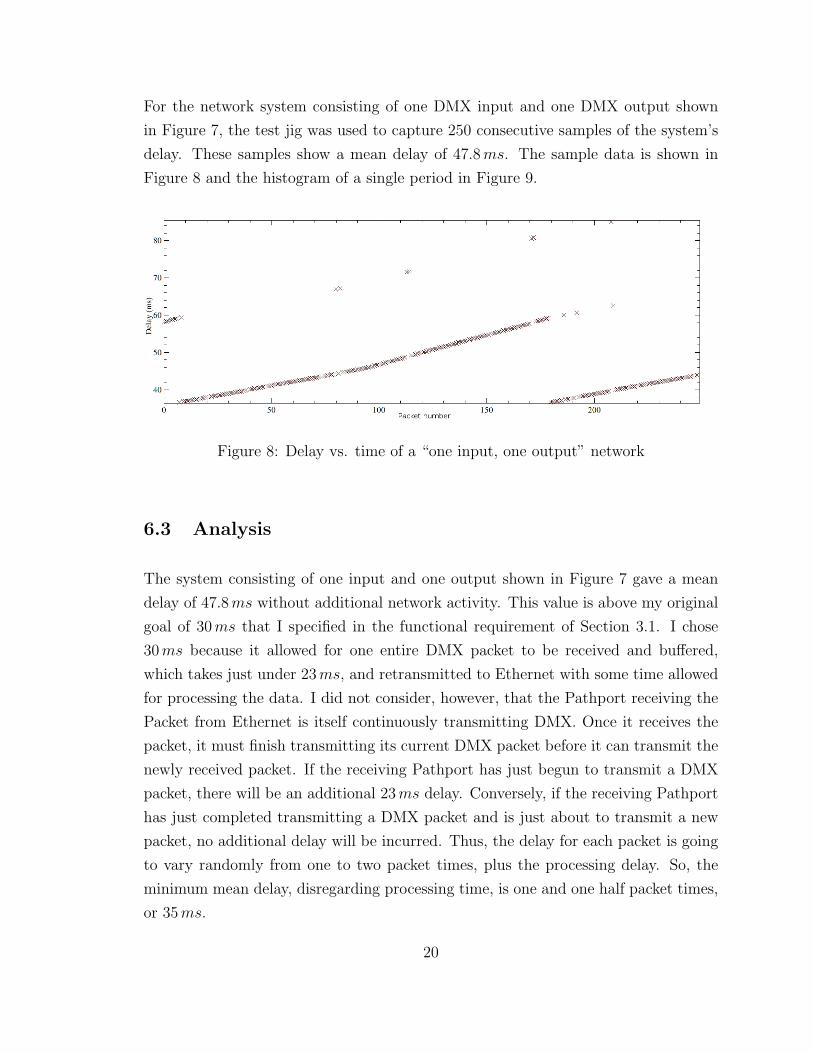
For the network system consisting of one DMX input and one DMX output shown
in Figure 7, the test jig was used to capture 250 consecutive samples of the system’s
delay. These samples show a mean delay of 47.8 ms. The sample data is shown in
Figure 8 and the histogram of a single period in Figure 9.
Figure 8: Delay vs. time of a “one input, one output” network
6.3 Analysis
The system consisting of one input and one output shown in Figure 7 gave a mean
delay of 47.8 ms without additional network activity. This value is above my original
goal of 30 ms that I specified in the functional requirement of Section 3.1. I chose
30 ms because it allowed for one entire DMX packet to be received and buffered,
which takes just under 23 ms, and retransmitted to Ethernet with some time allowed
for processing the data. I did not consider, however, that the Pathport receiving the
Packet from Ethernet is itself continuously transmitting DMX. Once it receives the
packet, it must finish transmitting its current DMX packet before it can transmit the
newly received packet. If the receiving Pathport has just begun to transmit a DMX
packet, there will be an additional 23 ms delay. Conversely, if the receiving Pathport
has just completed transmitting a DMX packet and is just about to transmit a new
packet, no additional delay will be incurred. Thus, the delay for each packet is going
to vary randomly from one to two packet times, plus the processing delay. So, the
minimum mean delay, disregarding processing time, is one and one half packet times,
or 35 ms.
20
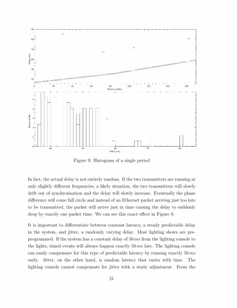
Figure 9: Histogram of a single period
In fact, the actual delay is not entirely random. If the two transmitters are running at
only slightly different frequencies, a likely situation, the two transmitters will slowly
drift out of synchronisation and the delay will slowly increase. Eventually the phase
difference will come full circle and instead of an Ethernet packet arriving just too late
to be transmitted, the packet will arrive just in time causing the delay to suddenly
drop by exactly one packet time. We can see this exact effect in Figure 8.
It is important to differentiate between constant latency, a steady predictable delay
in the system, and jitter, a randomly varying delay. Most lighting shows are pre-
programmed. If the system has a constant delay of 50 ms from the lighting console to
the lights, timed events will always happen exactly 50 ms late. The lighting console
can easily compensate for this type of predictable latency by running exactly 50 ms
early. Jitter, on the other hand, is random latency that varies with time. The
lighting console cannot compensate for jitter with a static adjustment. From the
21
experimental data shown in Figure 9, the system exhibits a mean latency of 47.8 ms,
and as discussed above a jitter of one half packet time, or roughly 11.5 ms.
7 Experiment #2: Dropped Packet Rate
7.1 Procedure
Each Ethernet packet carrying DMX data is tagged with a sequence number, which is
unique, modulus 216. Every packet that is transmitted by an input node is expected
to be received by the output node. If a packet is transmitted and not received, it
is considered to be “dropped”. An Ethernet network is a connection of devices –
data sources, packet switches, and data consumers. Any of these devices may drop a
packet if the device or the network itself becomes overloaded.
Additional traffic, for example, will cause collisions on the Ethernet backbone, which
are normal events on an Ethernet network. Following a collision, the transmitter
attempts to retransmit the packet a finite number of times, usually sixteen. If each of
those retransmissions fails, the transmitter eventually gives up and drops the packet.
A dropped packet is identified by a non-sequential jump in the received sequence
number. Duplicate packets, although rarely a problem and usually an indicator of
more fundamental network problems, are similarly identified by a duplicate sequence
number. An unusual event, such as a dropped or duplicate packet, is logged using
the Unix syslog facility.
To conduct this experiment, one DMX input port is patched to one DMX output
port. The receiving output DMX node is monitored for the following statistics:
• received packet rate (packets / second)
• dropped packet rate (%)
• processor utilisation (%)
22

Additional input nodes are connected to the system incrementally. These input nodes
are not patched to the output node, but their presence creates additional traffic on
the common network backbone. The additional input nodes are simulated using
the Pathport simulation described in Section 5. The input and output node being
monitored are actual Pathport hardware. The output Pathport node monitors the
number of received packets per second to ensure the simulated Pathports are loading
the network as expected.
7.2 Observation
Without additional traffic on the network, the system dropped no packets. Input
nodes were added to the network one by one and the processor utilisation and dropped
packet rate were recorded for this new level of traffic. No packets were dropped until
the network load was over 1200 packets per second, as shown in Figure 10. At this
packet load the processor is at just over 50% utilisation.
7.3 Analysis
Dimming of incandescent lighting is not particularly susceptible to a single dropped
packet. As mentioned before, the thermal inertia of the filament naturally smoothes
transitions between discrete dimming levels. If the stepper motor of a moving light
misses a packet, however, it will stay at its previous location for an additional packet
time and suddenly jump two units of distance. This coarse motion of the light beam
is quite noticeable to the human eye. As such the dropped packet rate should be kept
at a minimum, preferably zero.
The Ethernet backbone proved to be capable of carrying 1200 DMX packets per
second without any packet loss, which is 200 packets per second more than the re-
quirement of 1000 packets per second specified in the functional requirement of Sec-
tion 3.1. 1200 packets per second equates to roughly 27 DMX input ports if each port
is transmitting at the full DMX rate of 44 packets per second. Beyond this, random
packet collisions on the Ethernet backbone cause packet loss. Lost packets can cause
a smoothly fading light to appear jittery.
23

Figure 10: Processor utilisation and dropped packet rate vs. packets per second
Incidentally, a rule of thumb exists for Ethernet that states network performance
begins to suffer at 60% utilisation of the 10 Mbps maximum throughput. With
network protocol overhead, each DMX packet is 610 bytes in length or 4880 bits.
At 1200 packets per second, the network utilisation is 5.856 Mbps or nearly 59%
utilisation.
utilisation =fpacket · nbyte/packet · nbit/byte
fEthernet
=
1200 packets
· 610 bytepacket
· 8 bitbyte
10 Mb/s= 59% (5)
24

8 Experiment #3: Processor Use while Merging
8.1 Procedure
The Pathport is capable of merging multiple DMX streams into one output stream
as described in Section 4.3. Merging multiple DMX streams is a processor intensive
operation. Every incoming channel is buffered and compared with the value of every
other channel participating in the merge to decide the controlling channel. The
maximum number of merged channels is ultimately limited by the capability of the
processor.
The Pathport firmware runs through the main house-keeping loop whenever it is not
occupied with more important tasks, such as receiving lighting levels and controlling
the output DMX stream. The number of times the Pathport runs through the house-
keeping loop in a given time frame is a simple measure of how much spare time the
Pathport has and is thus related to processor utilisation.
This experiment measures the number of times the Pathport passes through the
house-keeping loop in one second and plots that value versus the number of universes
of DMX data being merged.
8.2 Observation
To establish a base line, the number of cycles through the house-keeping function is
measured without any active lighting data. Figure 11 shows the plot of house-keeping
cycles per second versus the number of merged channels.
Figure 12 shows the same data normalised to 0% processor utilisation at the base
line. In other words, it is transformed such that x′ = x0−xx0
, where x is the frequency
through the house keeping procedure measured above, x0 is the baseline frequency,
and x′ is the resulting normalised processor utilisation.
This plot shows the Pathport nears 100% processor utilisation when merging nine
channels of lighting data.
25
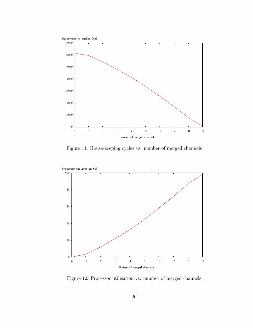
Figure 11: House-keeping cycles vs. number of merged channels
Figure 12: Processor utilisation vs. number of merged channels
26

8.3 Analysis
The Pathport is able to reliably merge nine channels, which is one more than the pro-
posed requirement of eight channels. At ten channels, the processor is overburdened
and will drop incoming packets to compensate.
When the Pathport is overburdened, it runs the main house-keeping loop at a mini-
mum rate of once every 200 ms and drops incoming packets to compensate. This is
slightly different than the dropped packets of Experiment #2, where the transmitter
was being forced to drop packets by an overburdened Ethernet backbone. In this ex-
periment, the receiving Pathport is choosing to drop packets due to lack of processing
time. The end result, however, is the the same. The packet does not make it from
the transmitting Pathport to the receiving Pathport.
9 Conclusions
Designing the Pathport has been a successful and enjoyable project. With some
tuning for performance, the Pathport met all the design requirements set out in the
functional specification. The network is able to maintain a load of one thousand
packets per second without measurable packet loss, and can merge eight individual
DMX streams into one output stream.
The Pathport simulator, running on Linux and commodity hardware, was developed
particularly for this thesis. Running a port of the embedded firmware on the devel-
oper’s machine became an undeniable benefit. It allowed debugging the embedded
software on a controlled, transparent system, allowed simulating more embedded de-
vices than were immediately available, and did so without the added difficulty of
cabling dozens of devices. The greatest benefit was being able to run unattended
test-suites to collect data for the experiments. Running the tests by hand would have
been tedious and potentially error prone.
The Pathport won an award for best new product at Lighting Dimensions Interna-
tional, the lighting industry trade show, in its first year and is now an established
product being sold worldwide by Pathway Connectivity.
27

References
[1] Pathway Connectivity Inc. http://www.pathwayconnect.com/ (2005-02-15).
[2] United States Institute for Theatre Technology, “Digital data transmission stan-
dard for dimmers and controllers,” Tech. Rep. DMX512, USITT, 1990. http:
//www.usitt.org/standards/DMX512.html (2005-02-09).
[3] Entertainment Services and Technology Association, “Entertainment technology
- multipurpose network control protocol suite,” 2005. Also known as Architecture
for Control Networks (ACN). http://www.esta.org/tsp/documents/public_
review_docs.php (2005-02-08).
[4] Infrared Data Association, “IrDA SIR data specification,” 1996. http://www.
irda.org/ (2005-03-18).
[5] Entertainment Services and Technology Association, “Control Protocols Working
Group.” http://www.esta.org/tsp/working_groups/cp.html (2005-03-24).
[6] Michael Stickel, “DMX4Linux,” 2003. http://llg.cubic.org/dmx4linux/
(2005-02-02).
[7] W. R. Stevens, UNIX Network Programming: Networking APIs: Sockets and XTI.
Prentice Hall PTR, 1997.
28