Embed Size (px)
Citation preview

Ethernet communicator E16T
USER MANUAL
UAB “TRIKDIS” Draugystės str. 17, LT-51229 Kaunas LITHUANIA E-mail: [email protected] Webpage: www.trikdis.lt

©1997-2017 Trikdis 2 www.trikdis.com
Ethernet communicator E16T
Contents SAFETY REQUIREMENTS .................................................................................................................................................2
DESCRIPTION ........................................................................................................................................................3
1.1 TECHNICAL PARAMETERS ...............................................................................................................................................3 1.2 COMMUNICATOR STRUCTURE ..........................................................................................................................................4 1.3 TERMINAL BLOCK DESCRIPTION ........................................................................................................................................4 1.4 LIGHT INDICATION .........................................................................................................................................................4 1.5 BEFORE YOU BEGIN .......................................................................................................................................................5 1.6 SYSTEM VIEW ...............................................................................................................................................................5
CONFIGURATION OF SECURITY CONTROL PANEL ..................................................................................................5
CONNECTING E16T TO TRIKDISCONFIG..................................................................................................................6
3.1 STATUS BAR .................................................................................................................................................................7
SETTING OPERATION PARAMETERS ......................................................................................................................7
4.1 SYSTEM SETTINGS .........................................................................................................................................................7 4.2 REPORTING → ALARM RECEIVING CENTRE (ARC) REPORTING ...............................................................................................8 4.3 REPORTING → PROTEGUS SERVICE ...................................................................................................................................9 4.4 EVENT SUMMARY .........................................................................................................................................................9
PHYSICAL INSTALLATION PROCESS ...................................................................................................................... 10
5.1 CONNECT THE COMMUNICATOR TO THE CONTROL PANEL USING WIRING DIAGRAM BELOW .........................................................10 5.2 (OPTIONAL) CONNECT SENSORS .....................................................................................................................................10 5.3 CONNECT LAN CABLE ..................................................................................................................................................10 5.4 TURN ON POWER SUPPLY..............................................................................................................................................10
PROTEGUS WEB SERVICE .................................................................................................................................... 10
TRIKDISCONFIG REMOTE CONTROL ..................................................................................................................... 11
PERFORM SYSTEM TEST ...................................................................................................................................... 12
MANUAL FIRMWARE UPDATE ............................................................................................................................. 12
Safety Requirements
The security alarm system should be installed and maintained by qualified personnel.
Prior to installation, please read carefully this manual in order to avoid mistakes that can lead to malfunction or even damage to the equipment.
Disconnect power before making any electrical connections.
Changes, modifications or repairs not authorized by the manufacturer shall void your rights under the warranty.
Please act according to your local rules and do not dispose of your unusable alarm system or its components with other household waste.
©1997-2017 Trikdis 3 www.trikdis.com
Ethernet communicator E16T
Description
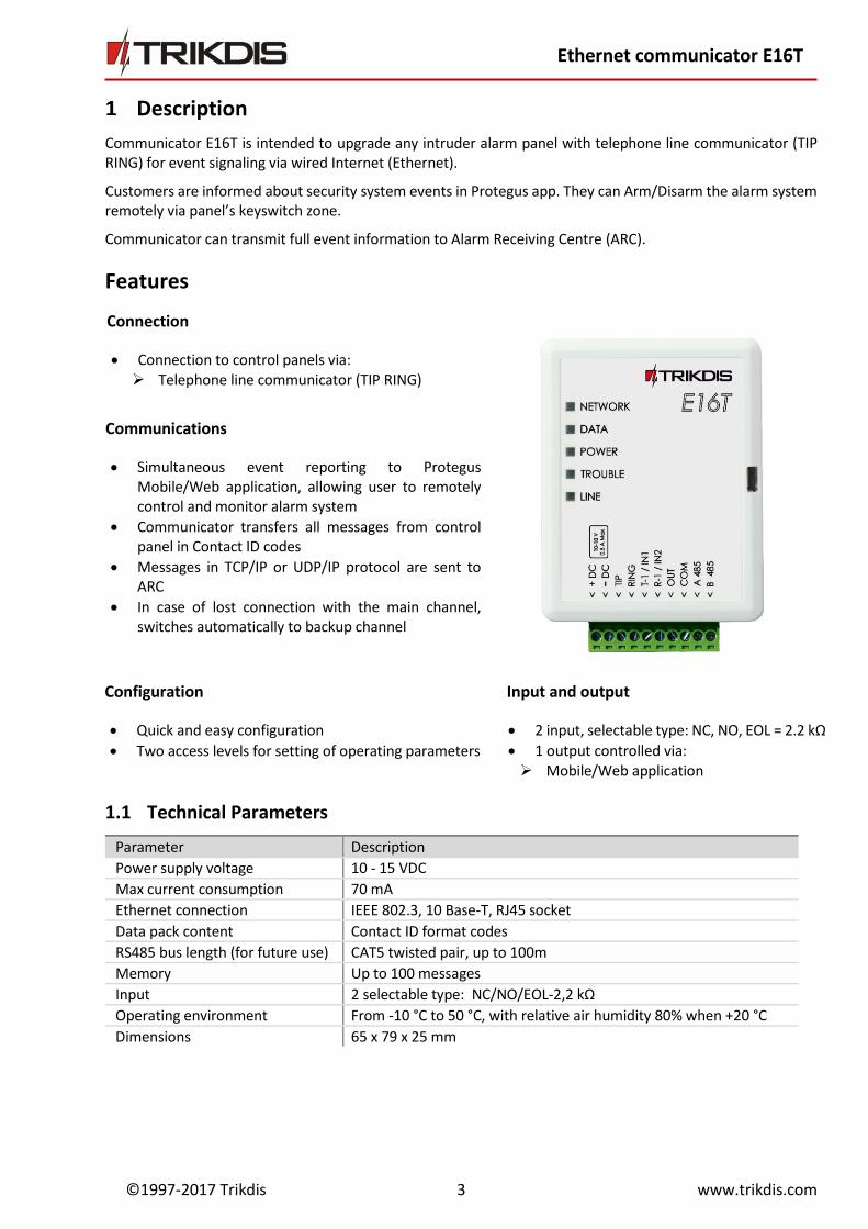
Communicator E16T is intended to upgrade any intruder alarm panel with telephone line communicator (TIP RING) for event signaling via wired Internet (Ethernet).
Customers are informed about security system events in Protegus app. They can Arm/Disarm the alarm system remotely via panel’s keyswitch zone.
Communicator can transmit full event information to Alarm Receiving Centre (ARC).
Features
1.1 Technical Parameters
Parameter Description
Power supply voltage 10 - 15 VDC
Max current consumption 70 mA
Ethernet connection IEEE 802.3, 10 Base-T, RJ45 socket
Data pack content Contact ID format codes
RS485 bus length (for future use) CAT5 twisted pair, up to 100m
Memory Up to 100 messages
Input 2 selectable type: NC/NO/EOL-2,2 kΩ
Operating environment From -10 °C to 50 °C, with relative air humidity 80% when +20 °C
Dimensions 65 x 79 x 25 mm
Connection
Connection to control panels via: Telephone line communicator (TIP RING)
Communications
Simultaneous event reporting to Protegus Mobile/Web application, allowing user to remotely control and monitor alarm system
Communicator transfers all messages from control panel in Contact ID codes
Messages in TCP/IP or UDP/IP protocol are sent to ARC
In case of lost connection with the main channel, switches automatically to backup channel
Input and output
2 input, selectable type: NC, NO, EOL = 2.2 kΩ
1 output controlled via: Mobile/Web application
Configuration
Quick and easy configuration
Two access levels for setting of operating parameters
©1997-2017 Trikdis 4 www.trikdis.com
Ethernet communicator E16T
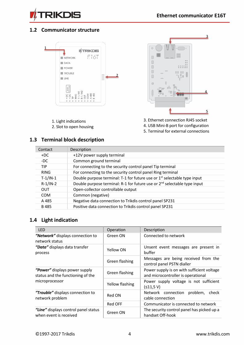
1.2 Communicator structure
1.3 Terminal block description
Contact Description
+DC +12V power supply terminal
-DC Common ground terminal
TIP For connecting to the security control panel Tip terminal
RING For connecting to the security control panel Ring terminal
T-1/IN-1 Double purpose terminal: T-1 for future use or 1st selectable type input
R-1/IN-2 Double purpose terminal: R-1 for future use or 2nd selectable type input
OUT Open-collector controllable output
COM Common (negative)
A 485 Negative data connection to Trikdis control panel SP231
B 485 Positive data connection to Trikdis control panel SP231
1.4 Light indication
LED Operation Description
“Network” displays connection to network status
Green ON Connected to network
“Data” displays data transfer process
Yellow ON Unsent event messages are present in buffer
Green flashing Messages are being received from the control panel PSTN dialler
“Power” displays power supply status and the functioning of the microprocessor
Green flashing Power supply is on with sufficient voltage and microcontroller is operational
Yellow flashing Power supply voltage is not sufficient (≤11,5 V)
“Trouble” displays connection to network problem
Red ON Network connection problem, check cable connection
Red OFF Communicator is connected to network
“Line” displays control panel status when event is received
Green ON The security control panel has picked up a handset Off-hook
1. Light indications 2. Slot to open housing
3. Ethernet connection RJ45 socket 4. USB Mini-B port for configuration 5. Terminal for external connections
1
2
3
4
5
©1997-2017 Trikdis 5 www.trikdis.com
Ethernet communicator E16T
Green OFF The security control panel has not picked up a handset On-hook
1.5 Before you begin
Before you begin, make sure that you have the necessary: 1) USB cable (Mini-B type, not included) for communicator E16T configuration. 2) CAT-5 Ethernet cable (maximum 100m, not included). 3) Flat-head screwdriver. 4) At least 4 wires cable for connecting communicator to control panel. 5) particular security control panel`s installation manual. Order them separately from your local distributor
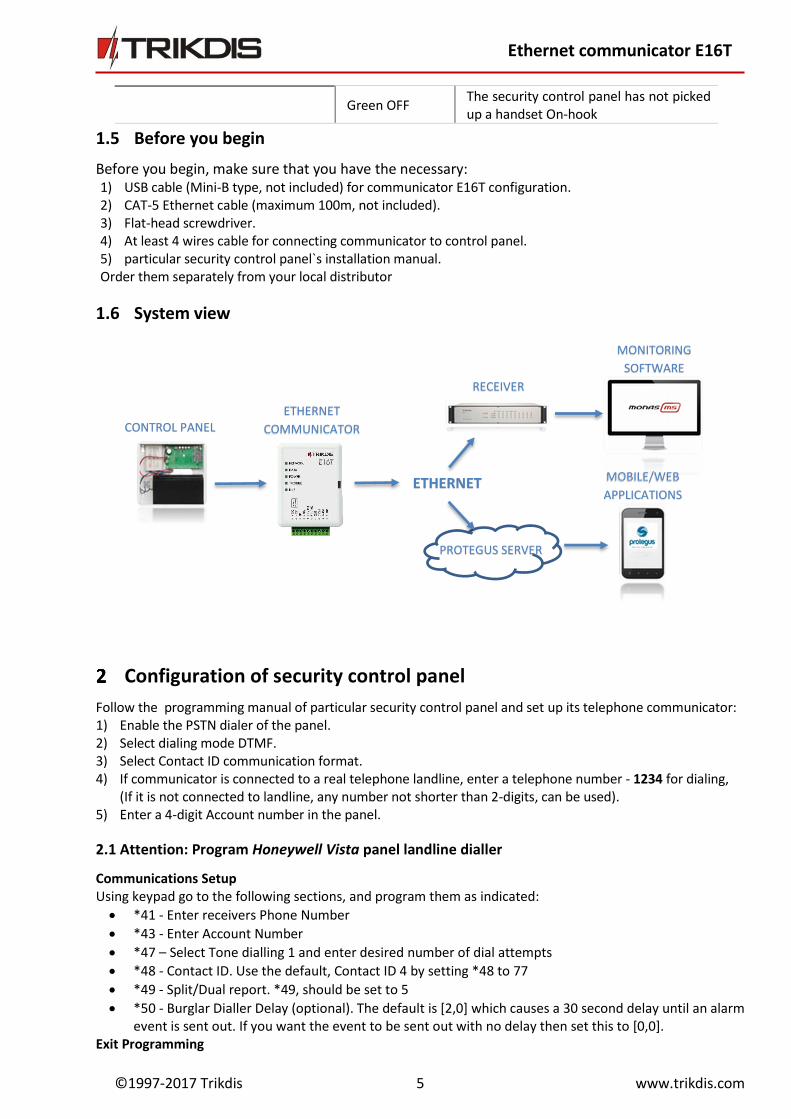
1.6 System view
Configuration of security control panel
Follow the programming manual of particular security control panel and set up its telephone communicator: 1) Enable the PSTN dialer of the panel. 2) Select dialing mode DTMF. 3) Select Contact ID communication format. 4) If communicator is connected to a real telephone landline, enter a telephone number - 1234 for dialing,
(If it is not connected to landline, any number not shorter than 2-digits, can be used). 5) Enter a 4-digit Account number in the panel.
2.1 Attention: Program Honeywell Vista panel landline dialler
Communications Setup Using keypad go to the following sections, and program them as indicated: *41 - Enter receivers Phone Number
*43 - Enter Account Number
*47 – Select Tone dialling 1 and enter desired number of dial attempts
*48 - Contact ID. Use the default, Contact ID 4 by setting *48 to 77
*49 - Split/Dual report. *49, should be set to 5
*50 - Burglar Dialler Delay (optional). The default is [2,0] which causes a 30 second delay until an alarm event is sent out. If you want the event to be sent out with no delay then set this to [0,0].
Exit Programming
MOBILE/WEB
APPLICATIONS ETHERNET
MONITORING
SOFTWARE
PROTEGUS SERVER
CONTROL PANEL ETHERNET
COMMUNICATOR
RECEIVER
©1997-2017 Trikdis 6 www.trikdis.com
Ethernet communicator E16T
Once all the sections are programmed, leave installers mode by entering *99 on the keypad.
Connecting E16T to TrikdisConfig
Communicator can be configured using TrikdisConfig software via USB cable or remotely. The software is
available on www.trikdis.com and operates in MS Windows OS.
1.1 Download and install TrikdisConfig. 1.2 Connect the communicator to the computer using USB cable or remotely.
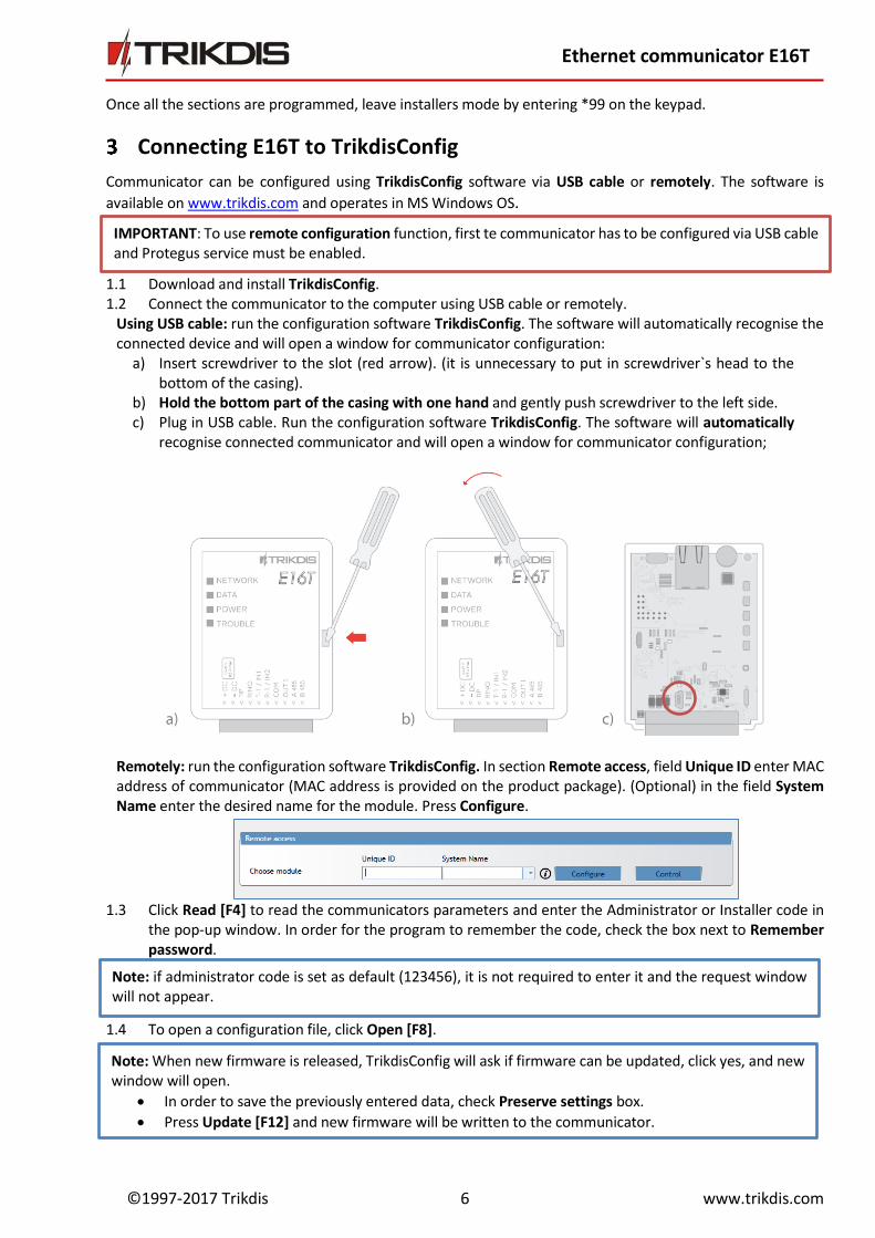
Using USB cable: run the configuration software TrikdisConfig. The software will automatically recognise the connected device and will open a window for communicator configuration:
a) Insert screwdriver to the slot (red arrow). (it is unnecessary to put in screwdriver`s head to the bottom of the casing).
b) Hold the bottom part of the casing with one hand and gently push screwdriver to the left side. c) Plug in USB cable. Run the configuration software TrikdisConfig. The software will automatically
recognise connected communicator and will open a window for communicator configuration;
Remotely: run the configuration software TrikdisConfig. In section Remote access, field Unique ID enter MAC address of communicator (MAC address is provided on the product package). (Optional) in the field System Name enter the desired name for the module. Press Configure.
1.3 Click Read [F4] to read the communicators parameters and enter the Administrator or Installer code in the pop-up window. In order for the program to remember the code, check the box next to Remember password.
1.4 To open a configuration file, click Open [F8].
Note: When new firmware is released, TrikdisConfig will ask if firmware can be updated, click yes, and new window will open.
In order to save the previously entered data, check Preserve settings box.
Press Update [F12] and new firmware will be written to the communicator.
IMPORTANT: To use remote configuration function, first te communicator has to be configured via USB cable and Protegus service must be enabled.
Note: if administrator code is set as default (123456), it is not required to enter it and the request window will not appear.
©1997-2017 Trikdis 7 www.trikdis.com
Ethernet communicator E16T
3.1 Status bar
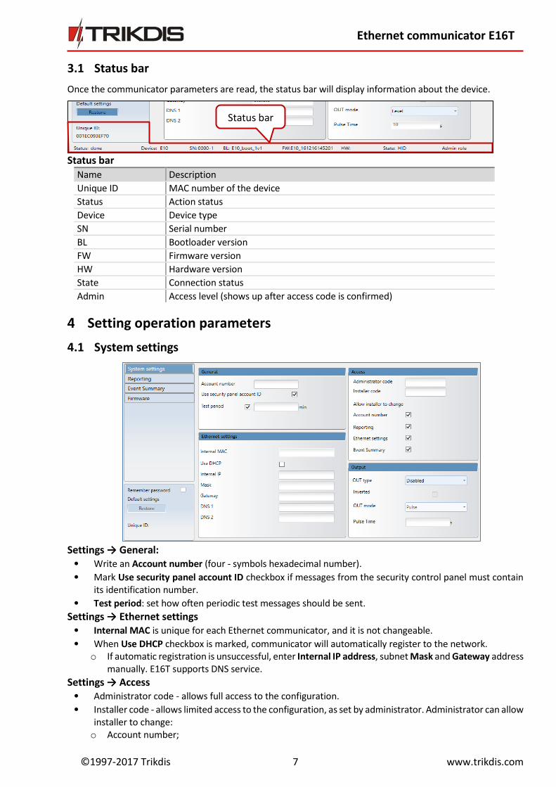
Once the communicator parameters are read, the status bar will display information about the device.
Status bar Name Description
Unique ID MAC number of the device
Status Action status
Device Device type
SN Serial number
BL Bootloader version
FW Firmware version
HW Hardware version
State Connection status
Admin Access level (shows up after access code is confirmed)
Setting operation parameters
4.1 System settings
Settings → General:
• Write an Account number (four - symbols hexadecimal number).
• Mark Use security panel account ID checkbox if messages from the security control panel must contain its identification number.
• Test period: set how often periodic test messages should be sent. Settings → Ethernet settings
• Internal MAC is unique for each Ethernet communicator, and it is not changeable.
• When Use DHCP checkbox is marked, communicator will automatically register to the network. o If automatic registration is unsuccessful, enter Internal IP address, subnet Mask and Gateway address
manually. E16T supports DNS service.
Settings → Access • Administrator code - allows full access to the configuration. • Installer code - allows limited access to the configuration, as set by administrator. Administrator can allow
installer to change: o Account number;
Status bar
©1997-2017 Trikdis 8 www.trikdis.com
Ethernet communicator E16T
o Reporting; o Ethernet settings; o Event summary.
Settings → Output • Choose output operation type from list OUT type.
• Mark Inverted checkbox if output function should be inverted.
• OUT mode: o Pulse: a status will be kept for a time period as indicated in Pulse Time (period in seconds) field.
o Level: a status will change and remain the same until the next command.
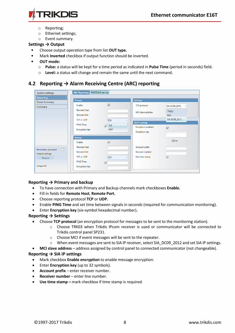
4.2 Reporting → Alarm Receiving Centre (ARC) reporting
Reporting → Primary and backup To have connection with Primary and Backup channels mark checkboxes Enable.
Fill in fields for Remote Host, Remote Port.
Choose reporting protocol TCP or UDP.
Enable PING Time and set time between signals in seconds (required for communication monitoring).
Enter Encryption key (six-symbol hexadecimal number).
Reporting → Settings Choose TCP protocol (an encryption protocol for messages to be sent to the monitoring station).
o Choose TRK03 when Trikdis IPcom receiver is used or communicator will be connected to Trikdis control panel SP231.
o Choose MCI if event messages will be sent to the repeater. o When event messages are sent to SIA IP receiver, select SIA_DC09_2012 and set SIA IP settings.
MCI slave address – address assigned by control panel to connected communicator (not changeable).
Reporting → SIA IP settings Mark checkbox Enable encryption to enable message encryption.
Enter Encryption key (up to 32 symbols).
Account prefix – enter receiver number.
Receiver number – enter line number.
Use time stamp – mark checkbox if time stamp is required.

©1997-2017 Trikdis 9 www.trikdis.com
Ethernet communicator E16T
4.3 Reporting → Protegus service
Protegus service allows end - users to remotely monitor and control status of their alarm system with the communicator and Protegus apps. For more information about PROTEGUS service visit http://www.protegus.eu/.
Enable cloud service at Reporting → PROTEGUS service tab.
Enter Service code (default code – 123456), for more safety change it to 6-symbol authentication code. This code is used, when adding new system to the application and controlling remotely via TrikdisConfig software (for more details refer to 5. TrikdisConfig remote control).
4.4 Event Summary
Event summary → Input description
• Describe input by filling in fields (these will be sent if Alarm/Restore occurs): o Partition; o Contact ID - can be customized or left default value; o Zone No - describe which zone will be controlled with IN 1, IN 2.
• Select Type of input (NO, NC, EOL).
• Enable: report when event occurs (Alarm); report when input line will restore (Restore).
Event summary → Internal events description • To describe internal events select event type (Event or Restore), enter Partitions and Zone numbers. • Contact ID code can be customized.
4.5 After all parameters are set, click Write [F5], to write parameters from TrikdisConfig program to communicator.
4.6 To create a configuration file which contains new parameters, click Save [F9]. 4.7 Disconnect device:
Click Disconnect to disconnect from access level (installer or admin) while communicator is connected via USB cable to a computer (role indication will be gone from status bar).
If a configuration is done via USB cable, unplug the USB cable; click Disconnect to go back to the main window.
©1997-2017 Trikdis 10 www.trikdis.com
Ethernet communicator E16T
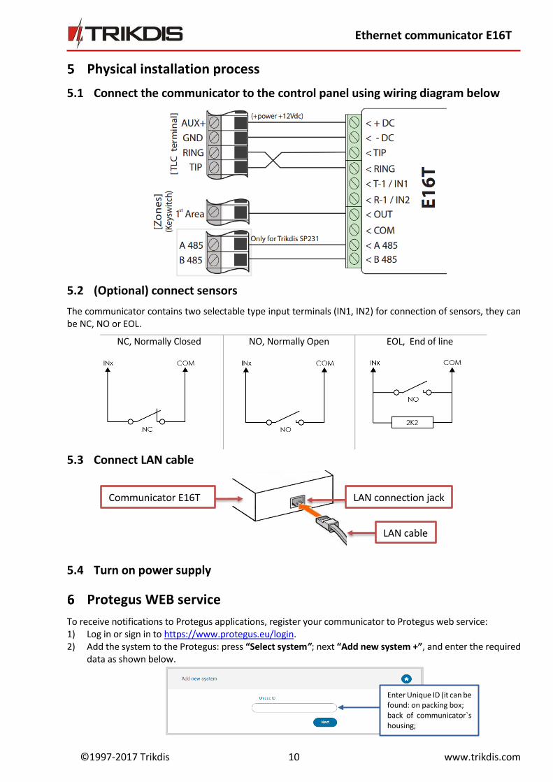
Physical installation process
5.1 Connect the communicator to the control panel using wiring diagram below
5.2 (Optional) connect sensors
The communicator contains two selectable type input terminals (IN1, IN2) for connection of sensors, they can be NC, NO or EOL.
5.3 Connect LAN cable
5.4 Turn on power supply
Protegus WEB service
To receive notifications to Protegus applications, register your communicator to Protegus web service: 1) Log in or sign in to https://www.protegus.eu/login. 2) Add the system to the Protegus: press “Select system”; next “Add new system +”, and enter the required
data as shown below.
NC, Normally Closed NO, Normally Open EOL, End of line
Communicator E16T
LAN cable
LAN connection jack
Enter Unique ID (it can be found: on packing box; back of communicator`s housing; in TrikdisConfig as
©1997-2017 Trikdis 11 www.trikdis.com
Ethernet communicator E16T
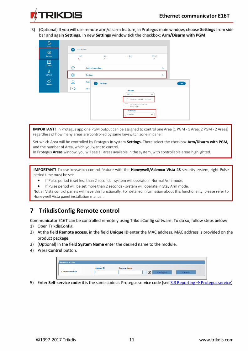
3) (Optional) If you will use remote arm/disarm feature, in Protegus main window, choose Settings from side bar and again Settings. In new Settings window tick the checkbox: Arm/Disarm with PGM
4)
5)
6)
7)
8)
9)
TrikdisConfig Remote control
Communicator E16T can be controlled remotely using TrikdisConfig software. To do so, follow steps below: 1) Open TrikdisConfig.
2) At the field Remote access, in the field Unique ID enter the MAC address. MAC address is provided on the
product package.
3) (Optional) In the field System Name enter the desired name to the module.
4) Press Control button.
5) Enter Self-service code: it is the same code as Protegus service code (see 3.3 Reporting → Protegus service).
IMPORTANT! In Protegus app one PGM output can be assigned to control one Area (1 PGM - 1 Area; 2 PGM - 2 Areas) regardless of how many areas are controlled by same keyswitch zone in panel.
Set which Area will be controlled by Protegus in system Settings. There select the checkbox Arm/Disarm with PGM, and the number of Area, which you want to control. In Protegus Areas window, you will see all areas available in the system, with controllable areas highlighted.
IMPORTANT! To use keyswitch control feature with the Honeywell/Ademco Vista 48 security system, right Pulse period time must be set:
If Pulse period is set less than 2 seconds - system will operate in Normal Arm mode.
If Pulse period will be set more than 2 seconds - system will operate in Stay Arm mode. Not all Vista control panels will have this functionally. For detailed information about this functionality, please refer to Honeywell Vista panel installation manual.
©1997-2017 Trikdis 12 www.trikdis.com
Ethernet communicator E16T
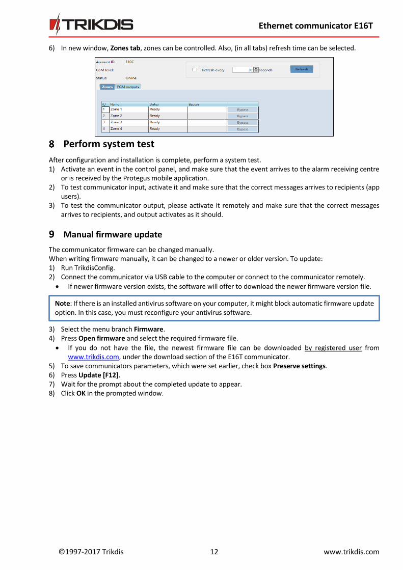
6) In new window, Zones tab, zones can be controlled. Also, (in all tabs) refresh time can be selected.
Perform system test
After configuration and installation is complete, perform a system test. 1) Activate an event in the control panel, and make sure that the event arrives to the alarm receiving centre
or is received by the Protegus mobile application. 2) To test communicator input, activate it and make sure that the correct messages arrives to recipients (app
users). 3) To test the communicator output, please activate it remotely and make sure that the correct messages
arrives to recipients, and output activates as it should.
Manual firmware update
The communicator firmware can be changed manually. When writing firmware manually, it can be changed to a newer or older version. To update: 1) Run TrikdisConfig. 2) Connect the communicator via USB cable to the computer or connect to the communicator remotely.
If newer firmware version exists, the software will offer to download the newer firmware version file.
3) Select the menu branch Firmware. 4) Press Open firmware and select the required firmware file.
If you do not have the file, the newest firmware file can be downloaded by registered user from www.trikdis.com, under the download section of the E16T communicator.
5) To save communicators parameters, which were set earlier, check box Preserve settings. 6) Press Update [F12]. 7) Wait for the prompt about the completed update to appear. 8) Click OK in the prompted window.
Note: If there is an installed antivirus software on your computer, it might block automatic firmware update option. In this case, you must reconfigure your antivirus software.