Embed Size (px)
Citation preview
Ethernet
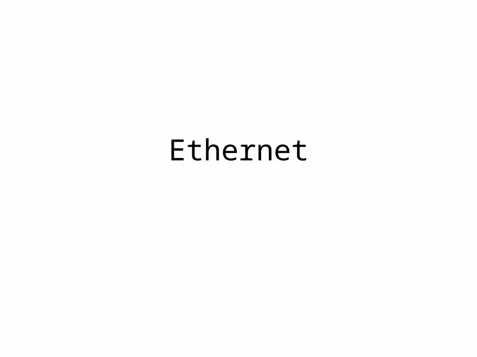
Direct connection: point-to-point
sendingnode
frame
rcvingnode
datagram
frame
adapter (NIC) adapter (NIC)
link layer protocol
• More than 2 nodes?
• 2 nodes:
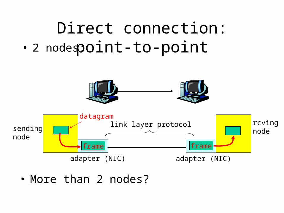
Direct connection: broadcast• Shared media
Metcalfe’s EthernetSketch (1973)
Ethernet “dominant” LAN technology:• cheap $30 for 100Mbs!• first widely used LAN technology• simpler, cheaper than token LANs and ATM• kept up with speed race: 10, 100, 1000 Mbps
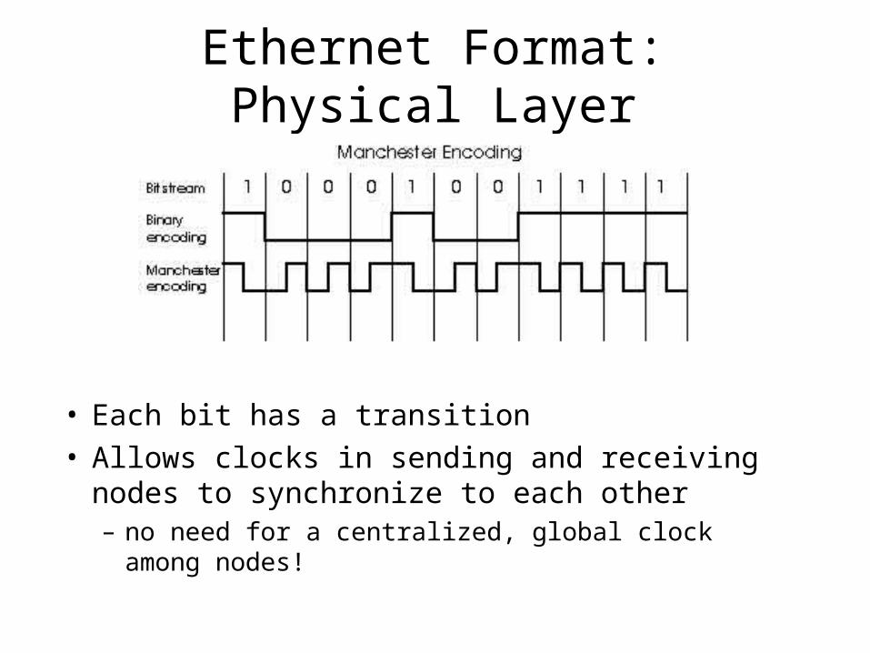
Ethernet Format: Physical Layer
• Each bit has a transition• Allows clocks in sending and receiving nodes to
synchronize to each other– no need for a centralized, global clock among nodes!
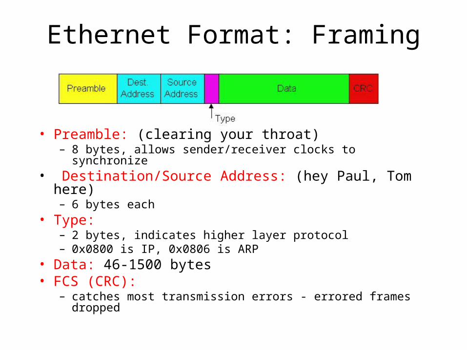
Ethernet Format: Framing
• Preamble: (clearing your throat)– 8 bytes, allows sender/receiver clocks to synchronize
• Destination/Source Address: (hey Paul, Tom here)– 6 bytes each
• Type: – 2 bytes, indicates higher layer protocol– 0x0800 is IP, 0x0806 is ARP
• Data: 46-1500 bytes• FCS (CRC):
– catches most transmission errors - errored frames dropped
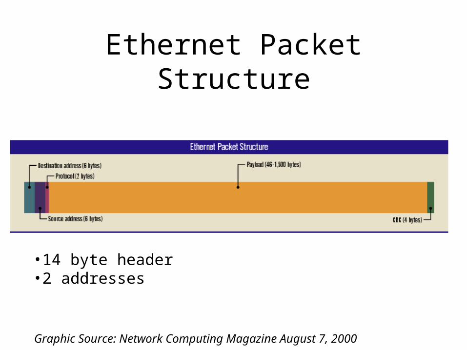
Ethernet Packet Structure
Graphic Source: Network Computing Magazine August 7, 2000
•14 byte header•2 addresses
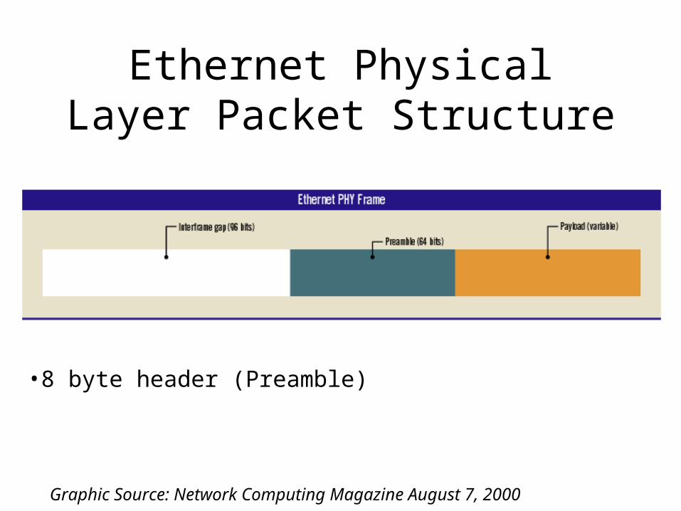
Ethernet Physical Layer Packet Structure
•8 byte header (Preamble)
Graphic Source: Network Computing Magazine August 7, 2000
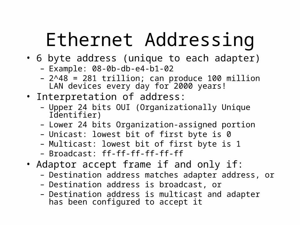
Ethernet Addressing• 6 byte address (unique to each adapter)
– Example: 08-0b-db-e4-b1-02– 2^48 = 281 trillion; can produce 100 million LAN devices every
day for 2000 years!• Interpretation of address:
– Upper 24 bits OUI (Organizationally Unique Identifier)– Lower 24 bits Organization-assigned portion– Unicast: lowest bit of first byte is 0– Multicast: lowest bit of first byte is 1– Broadcast: ff-ff-ff-ff-ff-ff
• Adaptor accept frame if and only if:– Destination address matches adapter address, or– Destination address is broadcast, or– Destination address is multicast and adapter has been configured
to accept it
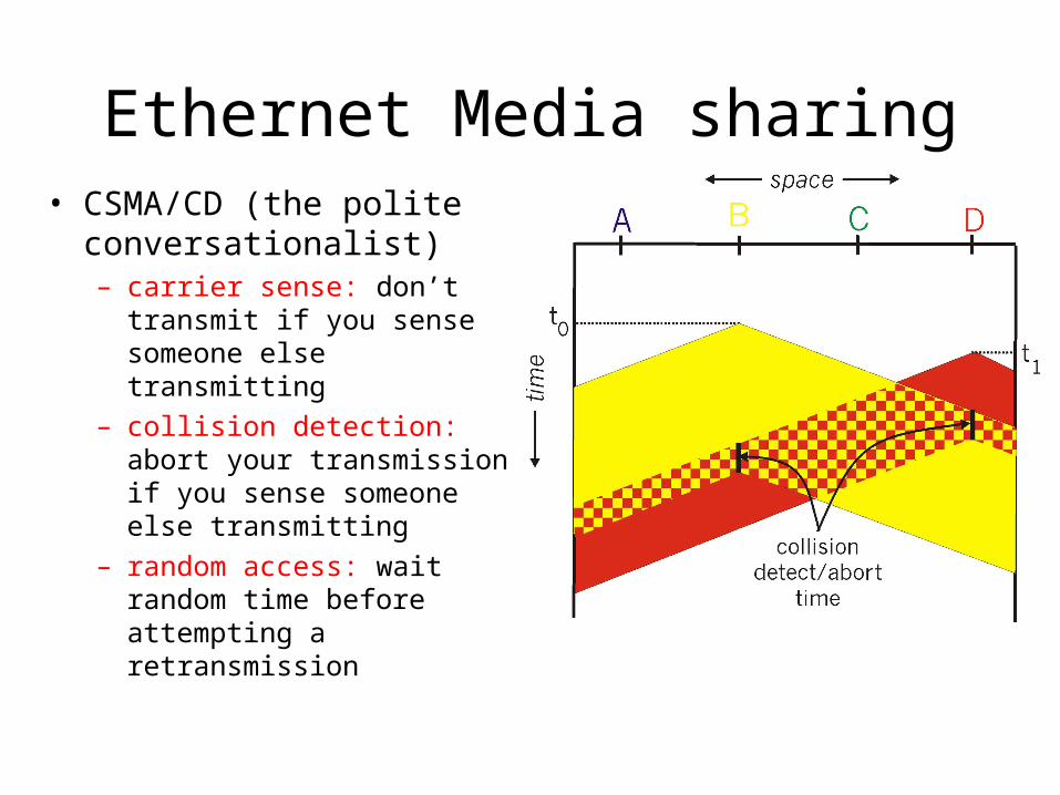
Ethernet Media sharing• CSMA/CD (the polite
conversationalist)– carrier sense: don’t transmit if
you sense someone else transmitting
– collision detection: abort your transmission if you sense someone else transmitting
– random access: wait random time before attempting a retransmission
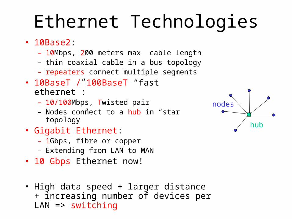
Ethernet Technologies• 10Base2:
– 10Mbps, 200 meters max cable length– thin coaxial cable in a bus topology– repeaters connect multiple segments
• 10BaseT / 100BaseT “fast ethernet”:– 10/100Mbps, Twisted pair– Nodes connect to a hub in “star topology”
• Gigabit Ethernet:– 1Gbps, fibre or copper– Extending from LAN to MAN
• 10 Gbps Ethernet now!
• High data speed + larger distance + increasing number of devices per LAN => switching
hub
nodes
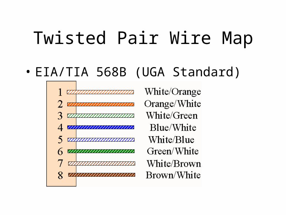
Twisted Pair Wire Map
• EIA/TIA 568B (UGA Standard)
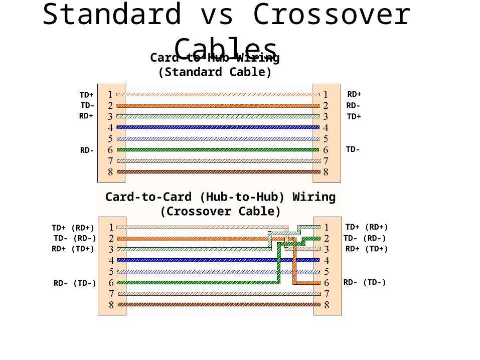
Standard vs Crossover CablesCard-to-Hub Wiring
(Standard Cable)
Card-to-Card (Hub-to-Hub) Wiring(Crossover Cable)
TD+TD- RD-
RD+
RD+
RD-
TD+
TD-
TD+ (RD+)TD- (RD-)
RD+ (TD+)
RD- (TD-)
TD+ (RD+)
TD- (RD-)RD+ (TD+)
RD- (TD-)
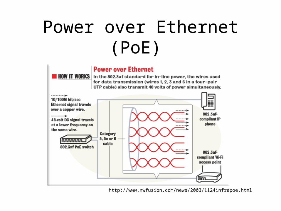
Power over Ethernet (PoE)
http://www.nwfusion.com/news/2003/1124infrapoe.html
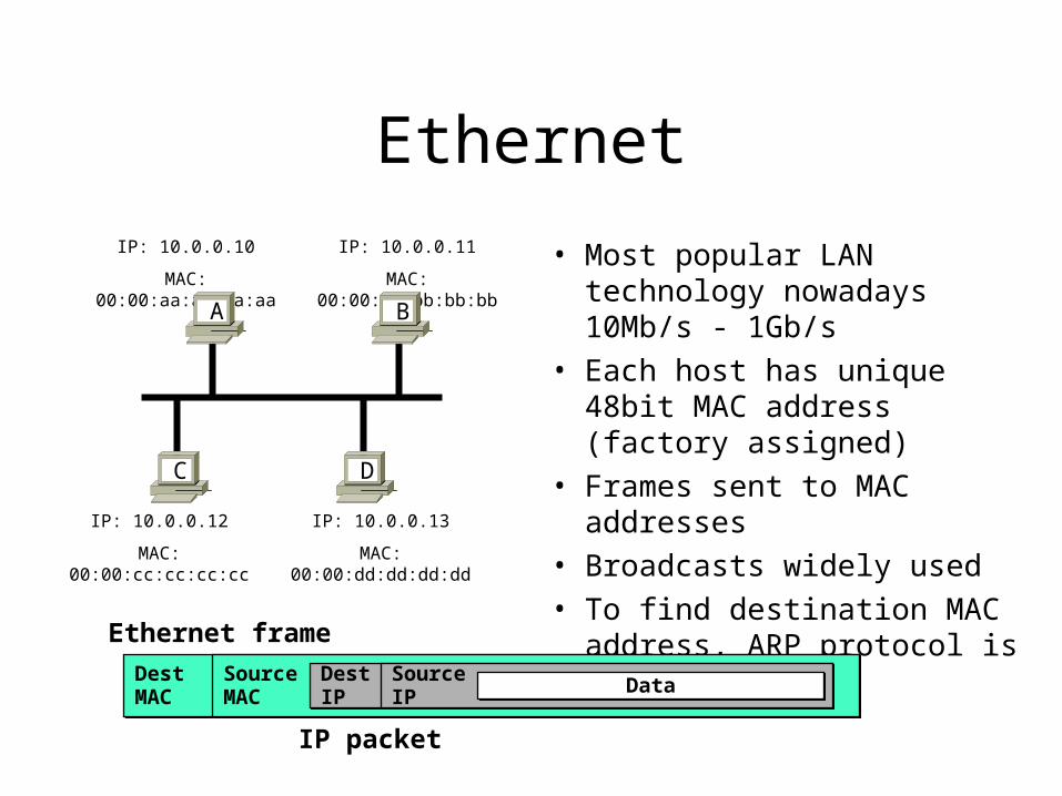
Ethernet
• Most popular LAN technology nowadays 10Mb/s - 1Gb/s
• Each host has unique 48bit MAC address (factory assigned)
• Frames sent to MAC addresses
• Broadcasts widely used
• To find destination MAC address, ARP protocol is used
IP: 10.0.0.10
MAC: 00:00:aa:aa:aa:aa
IP: 10.0.0.13
MAC: 00:00:dd:dd:dd:dd
IP: 10.0.0.12
MAC: 00:00:cc:cc:cc:cc
IP: 10.0.0.11
MAC: 00:00:bb:bb:bb:bb
A
DC
B
DestMACDestMAC
SourceMACSourceMAC
DestIPDestIP
SourceIPSourceIP DataData
Ethernet frame
IP packet
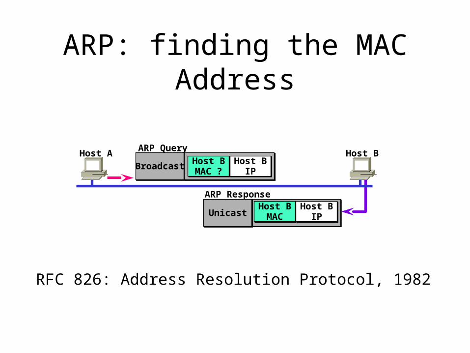
ARP: finding the MAC Address
Host A Host BARP Query
ARP Response
BroadcastBroadcast Host BMAC ?Host BMAC ?
Host BIP
Host BIP
Host BMAC
Host BMAC
Host BIP
Host BIPUnicastUnicast
RFC 826: Address Resolution Protocol, 1982
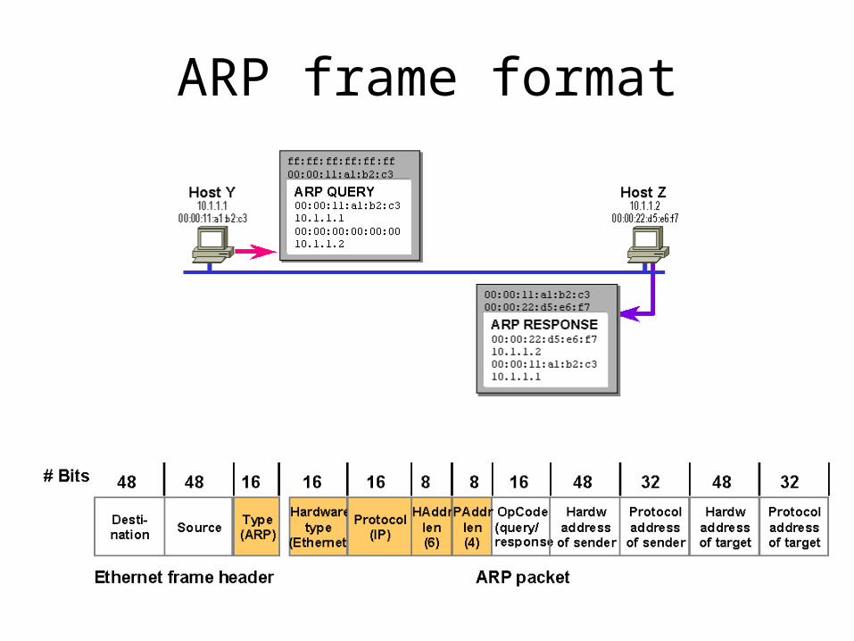
ARP frame format
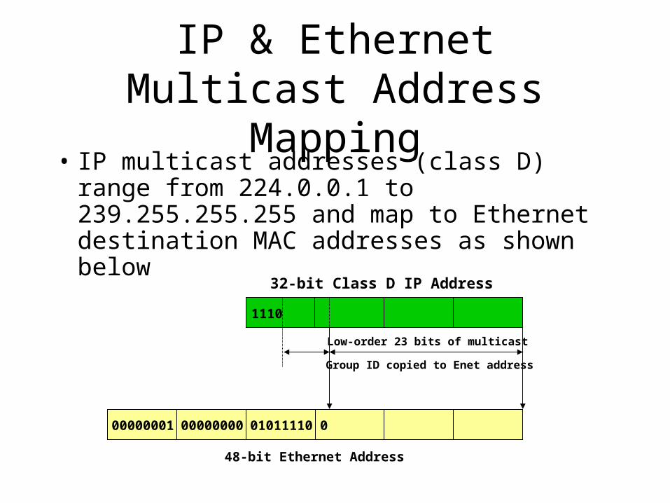
IP & Ethernet Multicast Address Mapping
• IP multicast addresses (class D) range from 224.0.0.1 to 239.255.255.255 and map to Ethernet destination MAC addresses as shown below
00000001 00000000 01011110 0
1110
Low-order 23 bits of multicast
Group ID copied to Enet address
32-bit Class D IP Address
48-bit Ethernet Address
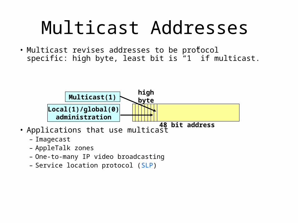
• Multicast revises addresses to be protocol specific: high byte, least bit is “1” if multicast.
• Applications that use multicast– Imagecast– AppleTalk zones– One-to-many IP video broadcasting– Service location protocol (SLP)
Multicast Addresses
Multicast(1)
Local(1)/global(0)administration
48 bit address
highbyte
IGMP Snooping• Internet Group Management Protocol (IGMP -
RFC 2236) used to manage IP multicast traffic• Application wishing to receive traffic for specific
IP multicast address sends out an ICMP join request (or a leave request to stop receiving multicast)
• Switches that employ IGMP snooping listen for IGMP join/leave requests to decide when to send a specific multicast frame to a port
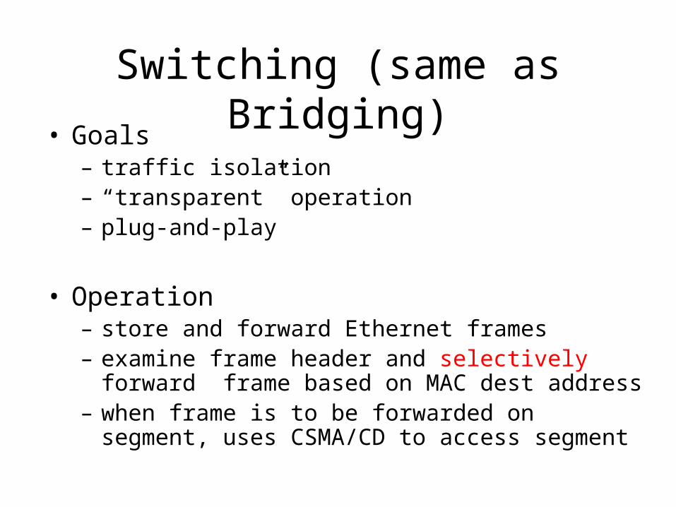
Switching (same as Bridging)• Goals
– traffic isolation– “transparent” operation– plug-and-play
• Operation– store and forward Ethernet frames– examine frame header and selectively forward frame based
on MAC dest address– when frame is to be forwarded on segment, uses CSMA/CD
to access segment
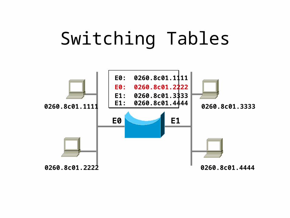
Switching Tables
0260.8c01.1111
0260.8c01.2222
0260.8c01.3333
0260.8c01.4444
E0 E1
E0: 0260.8c01.1111
E0: 0260.8c01.2222E1: 0260.8c01.3333E1: 0260.8c01.4444
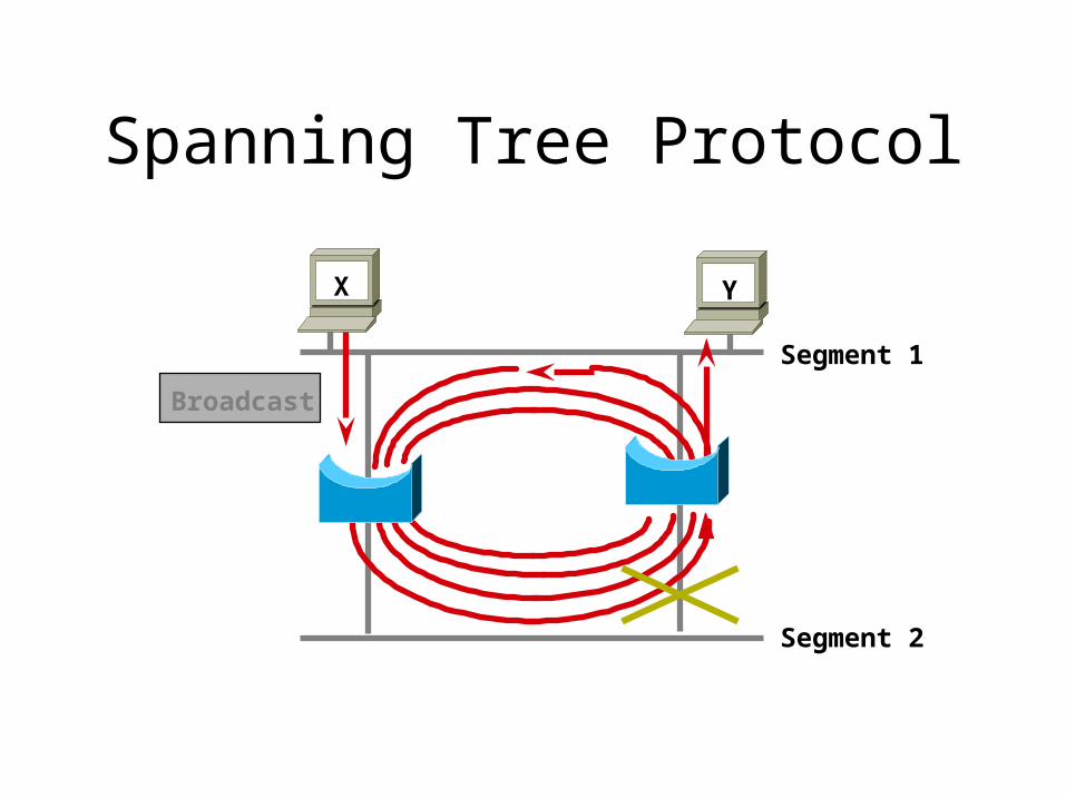
Spanning Tree Protocol
Broadcast
Segment 1
Segment 2
X Y
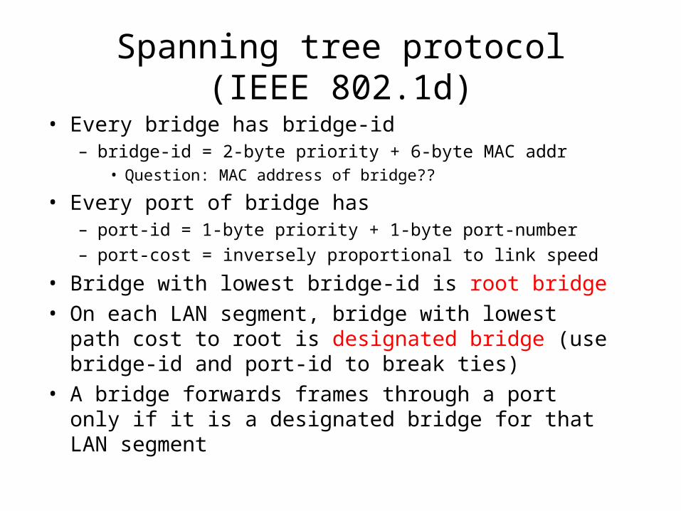
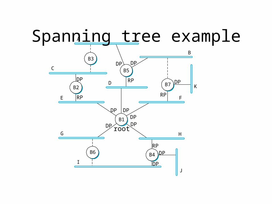
Spanning tree protocol (IEEE 802.1d)
• Every bridge has bridge-id– bridge-id = 2-byte priority + 6-byte MAC addr
• Question: MAC address of bridge??
• Every port of bridge has– port-id = 1-byte priority + 1-byte port-number
– port-cost = inversely proportional to link speed
• Bridge with lowest bridge-id is root bridge
• On each LAN segment, bridge with lowest path cost to root is designated bridge (use bridge-id and port-id to break ties)
• A bridge forwards frames through a port only if it is a designated bridge for that LAN segment
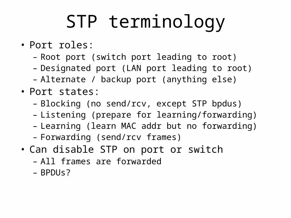
STP terminology• Port roles:
– Root port (switch port leading to root)– Designated port (LAN port leading to root)– Alternate / backup port (anything else)
• Port states:– Blocking (no send/rcv, except STP bpdus)– Listening (prepare for learning/forwarding)– Learning (learn MAC addr but no forwarding)– Forwarding (send/rcv frames)
• Can disable STP on port or switch– All frames are forwarded– BPDUs?
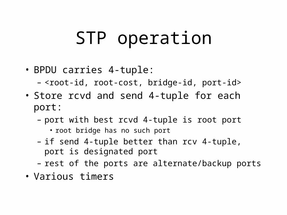
STP operation
• BPDU carries 4-tuple:– <root-id, root-cost, bridge-id, port-id>
• Store rcvd and send 4-tuple for each port:– port with best rcvd 4-tuple is root port
• root bridge has no such port
– if send 4-tuple better than rcv 4-tuple, port is designated port
– rest of the ports are alternate/backup ports
• Various timers
A
C
E
D
B
K
F
H
J
G
I
B5
B2
B3
B7
B4
B1
B6
Spanning tree example
rootDPDP
DPDP
DP
RP
DP
DP
DP
RP
RP
DPDP
DP
RP
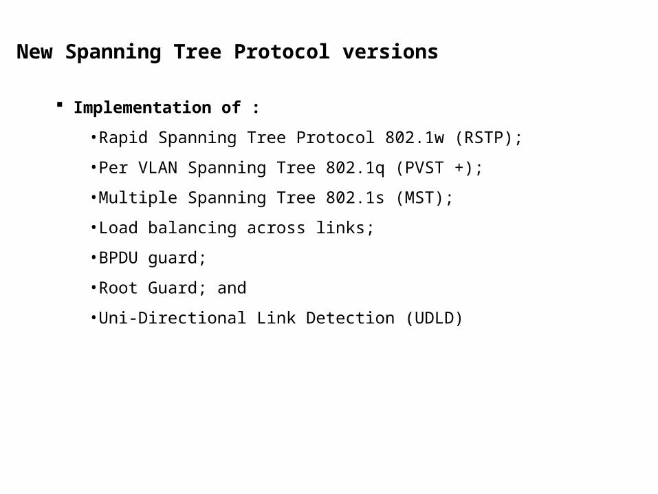
New Spanning Tree Protocol versions
Implementation of :
•Rapid Spanning Tree Protocol 802.1w (RSTP);
•Per VLAN Spanning Tree 802.1q (PVST +);
•Multiple Spanning Tree 802.1s (MST);
•Load balancing across links;
•BPDU guard;
•Root Guard; and
•Uni-Directional Link Detection (UDLD)
Evolution of Spanning Tree
The following developments in Spanning Tree Protocol are examined:
Per-VLAN Spanning Tree (PVST) is a Cisco-proprietary implementation requiring ISL trunk encapsulation.
PVST+ provides Layer 2 load balancing for the VLAN on which it runs.
MST (IEEE 802.1s) extends the IEEE 802.1w Rapid Spanning Tree (RST) algorithm to multiple spanning-trees.
Enhanced PVST + or Multiple Instance of Spanning Tree Protocol (MISTP), a compromise between PVST+ and MST.
802.1w Rapid Spanning Tree Protocol
The IEEE 802.1w specification, Rapid Spanning Tree Protocol, provides for subsecond reconvergence of STP after failure of one of the uplinks in a bridged environment.
802.1w provides the structure on which the 802.1s features such as multiple spanning tree operates.
There are only three port states left in RSTP corresponding to the three possible operational states Learning ,Forwarding and Discarding.
Rapid Transition to Forwarding State is the most important feature introduced by 802.1w:
• RSTP actively confirms safe port transition to forwarding without relying on timers;
• There is now a real feedback mechanism that takes place between RSTP-compliant bridges.
•In order to achieve fast convergence on a port, the protocol relies upon two new variables: edge ports and link type.
Virtual LANs
• LAN (broadcast domain) grows large• “departments” or “workgroups” not happy with
big broadcast domain– Security (eavesdropping)– Bandwidth consumed by flooding/multicasting
• Split LAN into multiple broadcast domains– Multiple physical LANs?
• Too expensive!• People move all the time!
• VLAN: logical partition of LAN
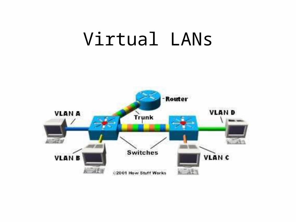
Virtual LANs
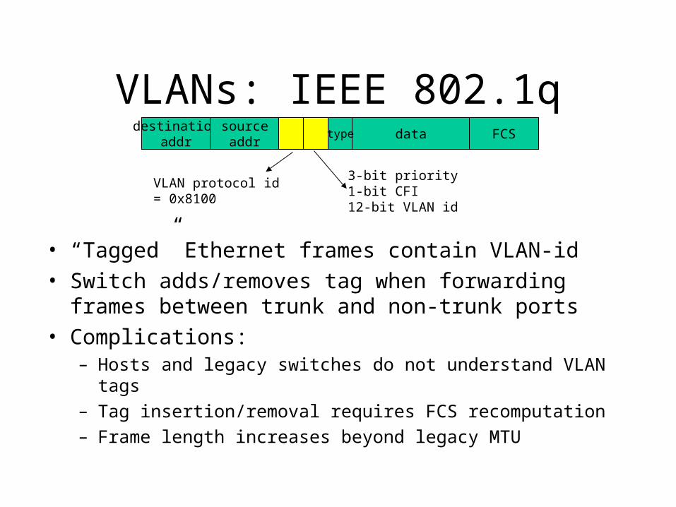
VLANs: IEEE 802.1q
• “Tagged” Ethernet frames contain VLAN-id
• Switch adds/removes tag when forwarding frames between trunk and non-trunk ports
• Complications:– Hosts and legacy switches do not understand VLAN tags
– Tag insertion/removal requires FCS recomputation
– Frame length increases beyond legacy MTU
destinationaddr
sourceaddr
data FCS
VLAN protocol id= 0x8100
3-bit priority1-bit CFI12-bit VLAN id
type
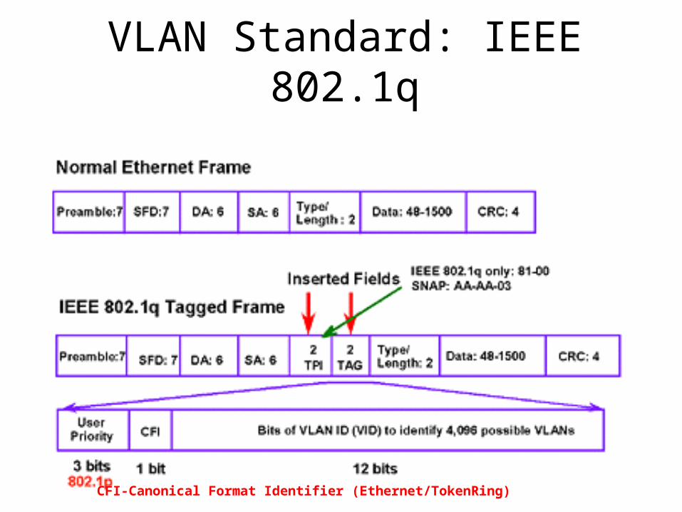
VLAN Standard: IEEE 802.1q
CFI-Canonical Format Identifier (Ethernet/TokenRing)
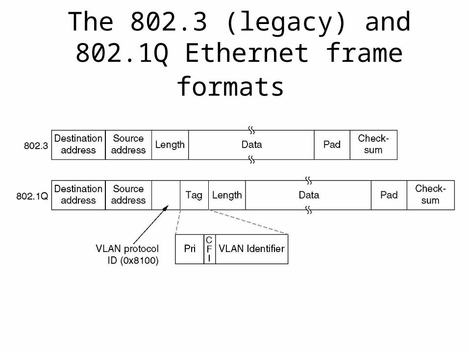
The 802.3 (legacy) and 802.1Q Ethernet frame formats
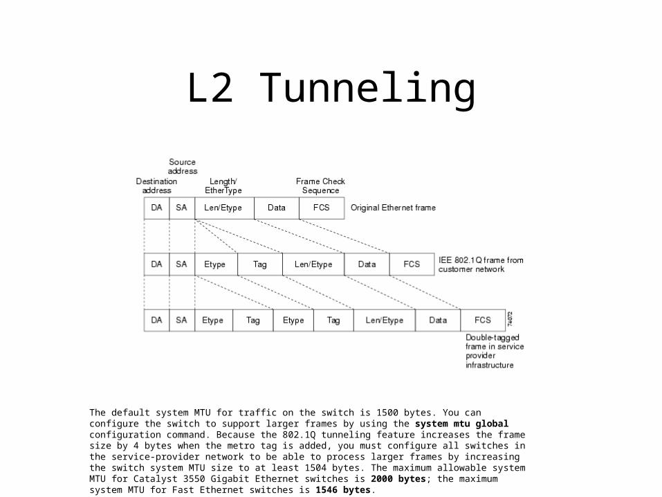
L2 Tunneling
The default system MTU for traffic on the switch is 1500 bytes. You can configure the switch to support larger frames by using the system mtu global configuration command. Because the 802.1Q tunneling feature increases the frame size by 4 bytes when the metro tag is added, you must configure all switches in the service-provider network to be able to process larger frames by increasing the switch system MTU size to at least 1504 bytes. The maximum allowable system MTU for Catalyst 3550 Gigabit Ethernet switches is 2000 bytes; the maximum system MTU for Fast Ethernet switches is 1546 bytes.
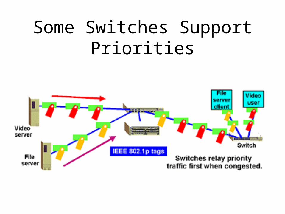
Some Switches Support Priorities
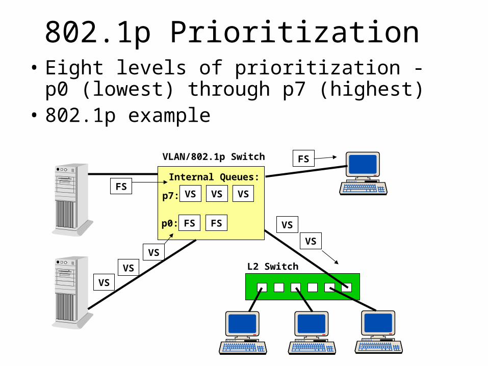
802.1p Prioritization• Eight levels of prioritization - p0 (lowest)
through p7 (highest)• 802.1p example
FS
VS
VS
VS
VS VS VS
VS
VS
FSFS
FSp7:
p0:
Internal Queues:
VLAN/802.1p Switch
L2 Switch
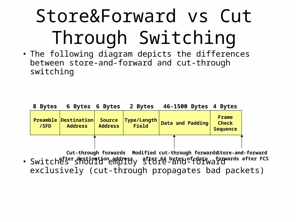
Store&Forward vs Cut Through Switching
• The following diagram depicts the differences between store-and-forward and cut-through switching
• Switches should employ store-and-forward exclusively (cut-through propagates bad packets)
Preamble/SFD
DestinationAddress
SourceAddress
Type/LengthField
Data and PaddingFrameCheck
Sequence
8 Bytes 6 Bytes 6 Bytes 2 Bytes 46-1500 Bytes 4 Bytes
Cut-through forwardsafter destination address
Modified cut-through forwardsafter 64 bytes of data
Store-and-forwardforwards after FCS
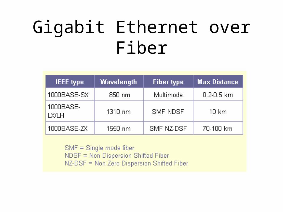
Gigabit Ethernet over Fiber
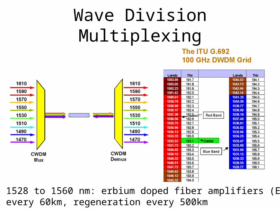
Wave Division Multiplexing
DWDM 1528 to 1560 nm: erbium doped fiber amplifiers (EDFA)EDFA every 60km, regeneration every 500km
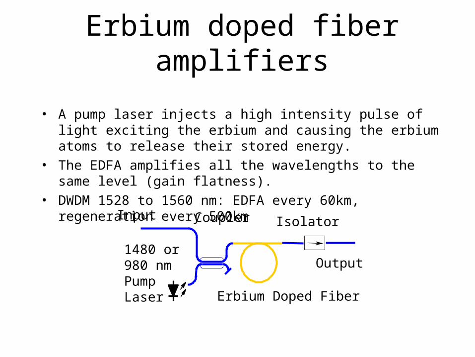
Erbium doped fiber amplifiers
• A pump laser injects a high intensity pulse of light exciting the erbium and causing the erbium atoms to release their stored energy.
• The EDFA amplifies all the wavelengths to the same level (gain flatness).
• DWDM 1528 to 1560 nm: EDFA every 60km, regeneration every 500km
Input
1480 or 980 nm Pump Laser Erbium Doped Fiber
Output
IsolatorCoupler
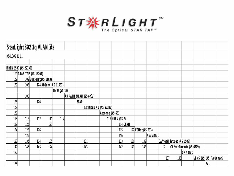
StarLight 802.1q VLAN Ids
MREN 6509 (AS 22335)101 STAR TAP (AS 10764)100 102 SURFNet (AS 1103)107 103 104 Abilene (AS 11537)
NWU (AS 103)105 AMPATH (VLAN 105 only)
128 106 6TAP108 128 MREN M5 (AS 22335)109 Argonne (AS 683)113 110 112 111 117 118 NREN (AS 24)119 120 121 114 CERN124 125 126 115 122 ESNet (AS 293)
129 116 NaukaNet123 130 134 135 131 133 136 132 CA*net-Winnipeg (AS 6509)147 146 145 144 143 142 141 140 X CA*net-Toronto (AS 6509)127 OMNINet
137 148 vBNS (AS 145) [Unknown]138 EVL
30-Jul-02 11:11
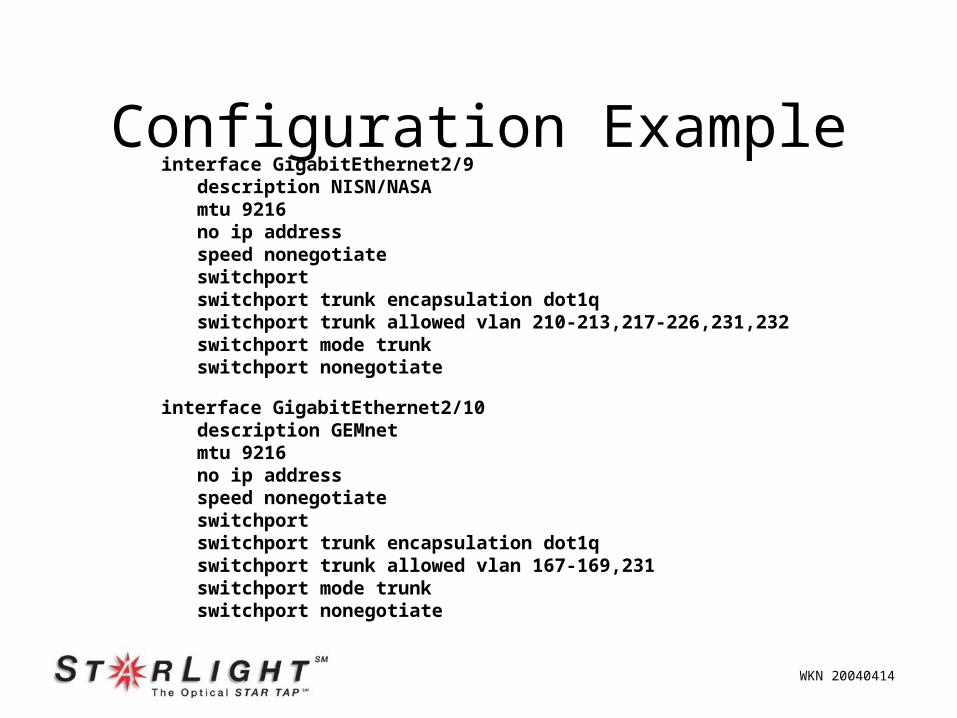
Configuration Exampleinterface GigabitEthernet2/9
description NISN/NASAmtu 9216no ip addressspeed nonegotiateswitchportswitchport trunk encapsulation dot1qswitchport trunk allowed vlan 210-213,217-226,231,232switchport mode trunkswitchport nonegotiate
interface GigabitEthernet2/10description GEMnetmtu 9216no ip addressspeed nonegotiateswitchportswitchport trunk encapsulation dot1qswitchport trunk allowed vlan 167-169,231switchport mode trunkswitchport nonegotiate
WKN 20040414